EP3371012B1 - Véhicule équipé d'un dispositif de freinage - Google Patents
Véhicule équipé d'un dispositif de freinage Download PDFInfo
- Publication number
- EP3371012B1 EP3371012B1 EP16805373.4A EP16805373A EP3371012B1 EP 3371012 B1 EP3371012 B1 EP 3371012B1 EP 16805373 A EP16805373 A EP 16805373A EP 3371012 B1 EP3371012 B1 EP 3371012B1
- Authority
- EP
- European Patent Office
- Prior art keywords
- unit
- braking
- brake
- vehicle according
- composite material
- Prior art date
- Legal status (The legal status is an assumption and is not a legal conclusion. Google has not performed a legal analysis and makes no representation as to the accuracy of the status listed.)
- Active
Links
- 239000002131 composite material Substances 0.000 claims description 25
- 230000000694 effects Effects 0.000 claims description 24
- 238000012544 monitoring process Methods 0.000 claims description 18
- 238000012806 monitoring device Methods 0.000 claims description 16
- 230000003647 oxidation Effects 0.000 claims description 9
- 238000007254 oxidation reaction Methods 0.000 claims description 9
- 238000013461 design Methods 0.000 claims description 7
- 239000000919 ceramic Substances 0.000 claims description 3
- 239000000835 fiber Substances 0.000 claims description 3
- 229910052799 carbon Inorganic materials 0.000 claims description 2
- OKTJSMMVPCPJKN-UHFFFAOYSA-N Carbon Chemical compound [C] OKTJSMMVPCPJKN-UHFFFAOYSA-N 0.000 claims 1
- 239000000463 material Substances 0.000 description 9
- 238000000034 method Methods 0.000 description 9
- 238000005516 engineering process Methods 0.000 description 4
- 229920000049 Carbon (fiber) Polymers 0.000 description 2
- 230000001133 acceleration Effects 0.000 description 2
- 239000004917 carbon fiber Substances 0.000 description 2
- 229910010293 ceramic material Inorganic materials 0.000 description 2
- 230000005520 electrodynamics Effects 0.000 description 2
- 230000006870 function Effects 0.000 description 2
- VNWKTOKETHGBQD-UHFFFAOYSA-N methane Chemical compound C VNWKTOKETHGBQD-UHFFFAOYSA-N 0.000 description 2
- 239000000126 substance Substances 0.000 description 2
- 229910001018 Cast iron Inorganic materials 0.000 description 1
- 229910001208 Crucible steel Inorganic materials 0.000 description 1
- 230000003679 aging effect Effects 0.000 description 1
- 239000003990 capacitor Substances 0.000 description 1
- 238000006243 chemical reaction Methods 0.000 description 1
- 230000006735 deficit Effects 0.000 description 1
- 238000001514 detection method Methods 0.000 description 1
- 238000011161 development Methods 0.000 description 1
- 230000018109 developmental process Effects 0.000 description 1
- 239000003733 fiber-reinforced composite Substances 0.000 description 1
- 239000011159 matrix material Substances 0.000 description 1
- 239000000203 mixture Substances 0.000 description 1
- 230000001172 regenerating effect Effects 0.000 description 1
- 239000012783 reinforcing fiber Substances 0.000 description 1
- HBMJWWWQQXIZIP-UHFFFAOYSA-N silicon carbide Chemical compound [Si+]#[C-] HBMJWWWQQXIZIP-UHFFFAOYSA-N 0.000 description 1
- 229910010271 silicon carbide Inorganic materials 0.000 description 1
- 238000012549 training Methods 0.000 description 1
Images
Classifications
-
- B—PERFORMING OPERATIONS; TRANSPORTING
- B60—VEHICLES IN GENERAL
- B60L—PROPULSION OF ELECTRICALLY-PROPELLED VEHICLES; SUPPLYING ELECTRIC POWER FOR AUXILIARY EQUIPMENT OF ELECTRICALLY-PROPELLED VEHICLES; ELECTRODYNAMIC BRAKE SYSTEMS FOR VEHICLES IN GENERAL; MAGNETIC SUSPENSION OR LEVITATION FOR VEHICLES; MONITORING OPERATING VARIABLES OF ELECTRICALLY-PROPELLED VEHICLES; ELECTRIC SAFETY DEVICES FOR ELECTRICALLY-PROPELLED VEHICLES
- B60L15/00—Methods, circuits, or devices for controlling the traction-motor speed of electrically-propelled vehicles
- B60L15/20—Methods, circuits, or devices for controlling the traction-motor speed of electrically-propelled vehicles for control of the vehicle or its driving motor to achieve a desired performance, e.g. speed, torque, programmed variation of speed
- B60L15/2009—Methods, circuits, or devices for controlling the traction-motor speed of electrically-propelled vehicles for control of the vehicle or its driving motor to achieve a desired performance, e.g. speed, torque, programmed variation of speed for braking
-
- B—PERFORMING OPERATIONS; TRANSPORTING
- B60—VEHICLES IN GENERAL
- B60L—PROPULSION OF ELECTRICALLY-PROPELLED VEHICLES; SUPPLYING ELECTRIC POWER FOR AUXILIARY EQUIPMENT OF ELECTRICALLY-PROPELLED VEHICLES; ELECTRODYNAMIC BRAKE SYSTEMS FOR VEHICLES IN GENERAL; MAGNETIC SUSPENSION OR LEVITATION FOR VEHICLES; MONITORING OPERATING VARIABLES OF ELECTRICALLY-PROPELLED VEHICLES; ELECTRIC SAFETY DEVICES FOR ELECTRICALLY-PROPELLED VEHICLES
- B60L15/00—Methods, circuits, or devices for controlling the traction-motor speed of electrically-propelled vehicles
- B60L15/20—Methods, circuits, or devices for controlling the traction-motor speed of electrically-propelled vehicles for control of the vehicle or its driving motor to achieve a desired performance, e.g. speed, torque, programmed variation of speed
-
- B—PERFORMING OPERATIONS; TRANSPORTING
- B60—VEHICLES IN GENERAL
- B60L—PROPULSION OF ELECTRICALLY-PROPELLED VEHICLES; SUPPLYING ELECTRIC POWER FOR AUXILIARY EQUIPMENT OF ELECTRICALLY-PROPELLED VEHICLES; ELECTRODYNAMIC BRAKE SYSTEMS FOR VEHICLES IN GENERAL; MAGNETIC SUSPENSION OR LEVITATION FOR VEHICLES; MONITORING OPERATING VARIABLES OF ELECTRICALLY-PROPELLED VEHICLES; ELECTRIC SAFETY DEVICES FOR ELECTRICALLY-PROPELLED VEHICLES
- B60L7/00—Electrodynamic brake systems for vehicles in general
- B60L7/24—Electrodynamic brake systems for vehicles in general with additional mechanical or electromagnetic braking
-
- B—PERFORMING OPERATIONS; TRANSPORTING
- B60—VEHICLES IN GENERAL
- B60T—VEHICLE BRAKE CONTROL SYSTEMS OR PARTS THEREOF; BRAKE CONTROL SYSTEMS OR PARTS THEREOF, IN GENERAL; ARRANGEMENT OF BRAKING ELEMENTS ON VEHICLES IN GENERAL; PORTABLE DEVICES FOR PREVENTING UNWANTED MOVEMENT OF VEHICLES; VEHICLE MODIFICATIONS TO FACILITATE COOLING OF BRAKES
- B60T1/00—Arrangements of braking elements, i.e. of those parts where braking effect occurs specially for vehicles
- B60T1/02—Arrangements of braking elements, i.e. of those parts where braking effect occurs specially for vehicles acting by retarding wheels
- B60T1/10—Arrangements of braking elements, i.e. of those parts where braking effect occurs specially for vehicles acting by retarding wheels by utilising wheel movement for accumulating energy, e.g. driving air compressors
-
- B—PERFORMING OPERATIONS; TRANSPORTING
- B60—VEHICLES IN GENERAL
- B60T—VEHICLE BRAKE CONTROL SYSTEMS OR PARTS THEREOF; BRAKE CONTROL SYSTEMS OR PARTS THEREOF, IN GENERAL; ARRANGEMENT OF BRAKING ELEMENTS ON VEHICLES IN GENERAL; PORTABLE DEVICES FOR PREVENTING UNWANTED MOVEMENT OF VEHICLES; VEHICLE MODIFICATIONS TO FACILITATE COOLING OF BRAKES
- B60T13/00—Transmitting braking action from initiating means to ultimate brake actuator with power assistance or drive; Brake systems incorporating such transmitting means, e.g. air-pressure brake systems
- B60T13/10—Transmitting braking action from initiating means to ultimate brake actuator with power assistance or drive; Brake systems incorporating such transmitting means, e.g. air-pressure brake systems with fluid assistance, drive, or release
- B60T13/58—Combined or convertible systems
- B60T13/585—Combined or convertible systems comprising friction brakes and retarders
- B60T13/586—Combined or convertible systems comprising friction brakes and retarders the retarders being of the electric type
-
- B—PERFORMING OPERATIONS; TRANSPORTING
- B60—VEHICLES IN GENERAL
- B60T—VEHICLE BRAKE CONTROL SYSTEMS OR PARTS THEREOF; BRAKE CONTROL SYSTEMS OR PARTS THEREOF, IN GENERAL; ARRANGEMENT OF BRAKING ELEMENTS ON VEHICLES IN GENERAL; PORTABLE DEVICES FOR PREVENTING UNWANTED MOVEMENT OF VEHICLES; VEHICLE MODIFICATIONS TO FACILITATE COOLING OF BRAKES
- B60T17/00—Component parts, details, or accessories of power brake systems not covered by groups B60T8/00, B60T13/00 or B60T15/00, or presenting other characteristic features
- B60T17/18—Safety devices; Monitoring
- B60T17/22—Devices for monitoring or checking brake systems; Signal devices
- B60T17/228—Devices for monitoring or checking brake systems; Signal devices for railway vehicles
-
- B—PERFORMING OPERATIONS; TRANSPORTING
- B60—VEHICLES IN GENERAL
- B60W—CONJOINT CONTROL OF VEHICLE SUB-UNITS OF DIFFERENT TYPE OR DIFFERENT FUNCTION; CONTROL SYSTEMS SPECIALLY ADAPTED FOR HYBRID VEHICLES; ROAD VEHICLE DRIVE CONTROL SYSTEMS FOR PURPOSES NOT RELATED TO THE CONTROL OF A PARTICULAR SUB-UNIT
- B60W30/00—Purposes of road vehicle drive control systems not related to the control of a particular sub-unit, e.g. of systems using conjoint control of vehicle sub-units, or advanced driver assistance systems for ensuring comfort, stability and safety or drive control systems for propelling or retarding the vehicle
- B60W30/18—Propelling the vehicle
- B60W30/18009—Propelling the vehicle related to particular drive situations
- B60W30/18109—Braking
- B60W30/18127—Regenerative braking
-
- B—PERFORMING OPERATIONS; TRANSPORTING
- B61—RAILWAYS
- B61H—BRAKES OR OTHER RETARDING DEVICES SPECIALLY ADAPTED FOR RAIL VEHICLES; ARRANGEMENT OR DISPOSITION THEREOF IN RAIL VEHICLES
- B61H9/00—Brakes characterised by or modified for their application to special railway systems or purposes
- B61H9/06—Brakes characterised by or modified for their application to special railway systems or purposes for storing energy during braking action
-
- F—MECHANICAL ENGINEERING; LIGHTING; HEATING; WEAPONS; BLASTING
- F16—ENGINEERING ELEMENTS AND UNITS; GENERAL MEASURES FOR PRODUCING AND MAINTAINING EFFECTIVE FUNCTIONING OF MACHINES OR INSTALLATIONS; THERMAL INSULATION IN GENERAL
- F16D—COUPLINGS FOR TRANSMITTING ROTATION; CLUTCHES; BRAKES
- F16D61/00—Brakes with means for making the energy absorbed available for use
-
- F—MECHANICAL ENGINEERING; LIGHTING; HEATING; WEAPONS; BLASTING
- F16—ENGINEERING ELEMENTS AND UNITS; GENERAL MEASURES FOR PRODUCING AND MAINTAINING EFFECTIVE FUNCTIONING OF MACHINES OR INSTALLATIONS; THERMAL INSULATION IN GENERAL
- F16D—COUPLINGS FOR TRANSMITTING ROTATION; CLUTCHES; BRAKES
- F16D69/00—Friction linings; Attachment thereof; Selection of coacting friction substances or surfaces
- F16D69/02—Compositions of linings; Methods of manufacturing
-
- H—ELECTRICITY
- H02—GENERATION; CONVERSION OR DISTRIBUTION OF ELECTRIC POWER
- H02P—CONTROL OR REGULATION OF ELECTRIC MOTORS, ELECTRIC GENERATORS OR DYNAMO-ELECTRIC CONVERTERS; CONTROLLING TRANSFORMERS, REACTORS OR CHOKE COILS
- H02P3/00—Arrangements for stopping or slowing electric motors, generators, or dynamo-electric converters
- H02P3/06—Arrangements for stopping or slowing electric motors, generators, or dynamo-electric converters for stopping or slowing an individual dynamo-electric motor or dynamo-electric converter
- H02P3/18—Arrangements for stopping or slowing electric motors, generators, or dynamo-electric converters for stopping or slowing an individual dynamo-electric motor or dynamo-electric converter for stopping or slowing an ac motor
- H02P3/26—Arrangements for stopping or slowing electric motors, generators, or dynamo-electric converters for stopping or slowing an individual dynamo-electric motor or dynamo-electric converter for stopping or slowing an ac motor by combined electrical and mechanical braking
-
- B—PERFORMING OPERATIONS; TRANSPORTING
- B60—VEHICLES IN GENERAL
- B60L—PROPULSION OF ELECTRICALLY-PROPELLED VEHICLES; SUPPLYING ELECTRIC POWER FOR AUXILIARY EQUIPMENT OF ELECTRICALLY-PROPELLED VEHICLES; ELECTRODYNAMIC BRAKE SYSTEMS FOR VEHICLES IN GENERAL; MAGNETIC SUSPENSION OR LEVITATION FOR VEHICLES; MONITORING OPERATING VARIABLES OF ELECTRICALLY-PROPELLED VEHICLES; ELECTRIC SAFETY DEVICES FOR ELECTRICALLY-PROPELLED VEHICLES
- B60L2200/00—Type of vehicles
- B60L2200/26—Rail vehicles
-
- F—MECHANICAL ENGINEERING; LIGHTING; HEATING; WEAPONS; BLASTING
- F16—ENGINEERING ELEMENTS AND UNITS; GENERAL MEASURES FOR PRODUCING AND MAINTAINING EFFECTIVE FUNCTIONING OF MACHINES OR INSTALLATIONS; THERMAL INSULATION IN GENERAL
- F16D—COUPLINGS FOR TRANSMITTING ROTATION; CLUTCHES; BRAKES
- F16D2200/00—Materials; Production methods therefor
- F16D2200/0034—Materials; Production methods therefor non-metallic
- F16D2200/0039—Ceramics
-
- F—MECHANICAL ENGINEERING; LIGHTING; HEATING; WEAPONS; BLASTING
- F16—ENGINEERING ELEMENTS AND UNITS; GENERAL MEASURES FOR PRODUCING AND MAINTAINING EFFECTIVE FUNCTIONING OF MACHINES OR INSTALLATIONS; THERMAL INSULATION IN GENERAL
- F16D—COUPLINGS FOR TRANSMITTING ROTATION; CLUTCHES; BRAKES
- F16D2200/00—Materials; Production methods therefor
- F16D2200/0034—Materials; Production methods therefor non-metallic
- F16D2200/0052—Carbon
-
- Y—GENERAL TAGGING OF NEW TECHNOLOGICAL DEVELOPMENTS; GENERAL TAGGING OF CROSS-SECTIONAL TECHNOLOGIES SPANNING OVER SEVERAL SECTIONS OF THE IPC; TECHNICAL SUBJECTS COVERED BY FORMER USPC CROSS-REFERENCE ART COLLECTIONS [XRACs] AND DIGESTS
- Y02—TECHNOLOGIES OR APPLICATIONS FOR MITIGATION OR ADAPTATION AGAINST CLIMATE CHANGE
- Y02T—CLIMATE CHANGE MITIGATION TECHNOLOGIES RELATED TO TRANSPORTATION
- Y02T10/00—Road transport of goods or passengers
- Y02T10/60—Other road transportation technologies with climate change mitigation effect
- Y02T10/64—Electric machine technologies in electromobility
-
- Y—GENERAL TAGGING OF NEW TECHNOLOGICAL DEVELOPMENTS; GENERAL TAGGING OF CROSS-SECTIONAL TECHNOLOGIES SPANNING OVER SEVERAL SECTIONS OF THE IPC; TECHNICAL SUBJECTS COVERED BY FORMER USPC CROSS-REFERENCE ART COLLECTIONS [XRACs] AND DIGESTS
- Y02—TECHNOLOGIES OR APPLICATIONS FOR MITIGATION OR ADAPTATION AGAINST CLIMATE CHANGE
- Y02T—CLIMATE CHANGE MITIGATION TECHNOLOGIES RELATED TO TRANSPORTATION
- Y02T10/00—Road transport of goods or passengers
- Y02T10/60—Other road transportation technologies with climate change mitigation effect
- Y02T10/72—Electric energy management in electromobility
Definitions
- the invention relates to a vehicle with a brake device which has at least one friction brake unit, an electric brake unit and a brake control device.
- Generic vehicles are in DE 10 2009 051019 A1 and DE 10 2012 203132 A1 described.
- WO 97/38235 A1 describes the use of a fiber reinforced composite material for brake components.
- Vehicles are known in which a braking force is generated by electric motors.
- the kinetic energy of the vehicle converted into electrical energy by the motors during braking is e.g. converted into heat via a braking resistor or fed back into the rail supply network or into a mobile memory.
- the vehicles In addition to the electrodynamic, regenerative brake, the vehicles usually continue to have a full friction brake, in which the braking effect is achieved by pneumatic, hydraulic and / or mechanical means.
- the invention has for its object to provide a vehicle with a safe and structurally simple braking device.
- a vehicle according to claim 1 is proposed.
- advantageous weight savings can be achieved with at least unchanged safety of the braking device.
- the invention is based on the consideration that an advantageous relief of the friction brake unit can be achieved with a targeted, priority use of the electric brake unit. Thanks to the monitoring device, a high level of security when using the Electric braking unit can be achieved so that it can also be used as a priority over the friction braking unit for carrying out safety braking - especially in the worst case of full braking based on the vehicle's highest permitted speed and / or on a downhill gradient.
- the number of cases that can occur during the life of the brake components of the friction brake unit and in which such full braking must be carried out predominantly or completely by means of the friction brake unit can accordingly be kept low. In this way, a long service life of the friction brake unit can be achieved.
- the invention is based on the further consideration that a brake component made of a composite material is quite capable of being operated without damage in a high temperature range - typically at temperatures above 800 ° C. Although these temperatures are far above the typical temperatures at which an oxidation of conventional, commercially available composite materials and associated disadvantages occur, such a exceeding of these critical oxidation limit temperatures is not very critical in these rare cases of full braking without the involvement of the electric braking unit.
- the friction brake unit can be relieved to such an extent that it does not exceed the corresponding oxidation limit temperature in most braking cases - also called "service braking". It is therefore possible to use commercially available lightweight composite materials for the friction brake unit for the design of a safe braking device, which are designed for medium operating temperatures below 550 ° C.
- the brake components of the friction brake unit made of a composite material are in particular brake disks.
- brake pads made of organic or ceramic materials can be used.
- a “composite” is a material made from at least two joined materials that has different material properties than its individual components. Fiber composite materials which have an embedding matrix made of a first material and reinforcing fibers made of a second material are particularly advantageous for use in brake components. The use of a carbon fiber composite material also offers the advantage of high mechanical strength.
- the monitoring of a braking process carried out by means of the electric braking unit is expediently based on the detection of at least one braking effect parameter.
- a “braking effect parameter” is to be understood in particular as a parameter by means of which at least information about a braking effect of the electrical braking unit can be obtained. This braking effect can be a braking effect achieved by means of the electric braking unit or a braking effect which can be achieved by operating a brake control unit to control it.
- the monitoring device can comprise a sensor unit, by means of which at least one operating parameter related to the vehicle, such as e.g. a current speed parameter, a current acceleration parameter, a braking force parameter, etc. can be detected.
- a “braking effect” can be understood in particular to mean a braking force or a braking torque which can be transferred to at least one vehicle wheel unit, in particular a vehicle wheel set, or a braking power.
- the monitoring of a braking process carried out by means of the electrical braking unit preferably includes at least the monitoring of a braking control unit which is provided for controlling the electrical braking unit when the braking process is carried out.
- the monitoring device can evaluate control signals generated by an active brake control unit for controlling the electrical brake unit in order to determine a braking effect that can be achieved with the control signals.
- the brake control device expediently has at least one brake control unit for controlling the electrical brake unit and at least one brake control unit for controlling the friction brake unit.
- These brake units are preferably different from one another in terms of software and / or hardware.
- the monitoring device expediently has at least one monitoring unit for monitoring a brake control unit assigned to the electric brake unit, the monitoring unit and the brake control unit being two different, in particular separate, units.
- An “electrical braking unit” is to be understood in particular as a braking unit in which at least part of the kinetic energy of the vehicle is converted into electrical energy in one braking operation.
- the electric brake unit can have an eddy current brake.
- the vehicle can have a storage unit in which at least part of an electrical energy generated by the electrical braking unit during the braking process is stored and which has at least one battery and / or at least one double-layer capacitor.
- the electrical brake unit have at least one drive unit of the drive device of the vehicle.
- the drive unit typically has at least one drive motor mechanically coupled to a drive wheel unit of the vehicle and a power supply unit which is provided in a traction mode of the vehicle for generating electrical power for the drive motor.
- the electric brake unit the power supply unit or its controllable power electronic elements are expediently controlled by means of an associated brake control unit such that a braking torque which can be transmitted to a drive wheel unit of the vehicle is generated by means of the drive motor which is operatively connected to the power supply unit.
- the monitoring of a braking process carried out by means of the electrical braking unit preferably includes monitoring of the drive motor, a power supply unit assigned to it and / or the assigned brake control unit for controlling the power supply unit.
- a drive wheel unit of the vehicle can have a wheelset shaft to which vehicle wheels are coupled.
- the drive wheel unit can correspond to a drive axle of the vehicle.
- drive wheel units of the vehicle can be vehicle wheels that are independent of one another and can be driven in each case.
- a plurality of vehicle wheels are each assigned at least one of the brake components of the friction brake unit and a drive unit of the drive device, the drive unit being part of the electrical brake unit.
- This drive unit can have a wheel hub drive.
- the brake control device is expediently provided to carry out a braking operation with the electric braking unit as a priority in a normal braking mode of the braking device.
- This is to be understood to mean that a predominant part of the braking effect to be achieved in the braking process is to be generated as far as possible by the electrical braking unit.
- a braking effect to be achieved is demanded by a vehicle driver, a vehicle control system and / or an emergency braking device of the vehicle.
- the friction brake unit advantageously serves to support the electric brake unit.
- the brake control device be provided to activate a safety mode of the friction brake unit in the event of a restriction of the electrical brake unit detected by the monitoring device.
- a high level of security can be achieved in this way.
- a restriction of the electric brake unit can be caused by a fault in the actuatable components of the electric brake unit and / or a brake control unit provided for controlling these components.
- the electrical brake unit is formed by at least one drive unit of a drive device of the vehicle, a restriction can be caused by an error in a drive component of the drive unit. This can be a fault in a drive motor and / or a power supply unit assigned to it.
- the fault can be caused by a brake control unit provided to control this power supply unit.
- a "limitation" of the electric brake unit can be a partial failure, in which the electric brake unit can produce a smaller braking action than a braking action that can be generated in the fault-free case, or a total failure.
- the safety mode expediently comprises at least the compensation of a braking action which is insufficient due to the restriction or the generation of the braking action which can normally be generated by the electrical braking unit.
- the safety mode can, in particular, include performing full braking.
- a particularly high level of safety can be achieved if the brake control device has at least two brake control units for controlling the electric brake unit, which are designed to be redundant or diversely redundant with respect to one another. Two units are considered "diversely redundant" if one unit is used for a fallback strategy in the event of a fault in the other unit and the units are based on different technologies in terms of design and / or software.
- the brake control device have at least two brake control units for controlling the electric brake unit and that the monitoring device comprises at least two different monitoring units, each of which is assigned to a different brake control unit.
- the monitoring device comprises at least two different monitoring units, each of which is assigned to a different brake control unit.
- the brake control device be provided to control the friction brake unit to compensate for the braking action if the braking action of the electric braking unit is detected by means of the monitoring device and lacks a desired braking effect.
- the difference in the braking action provided or achievable by the electric braking unit to the desired braking action by the friction braking unit can be compensated for particularly advantageously by the braking action compensation.
- the composite material be a ceramic composite material.
- a ceramic material is to be understood as a material whose chemical composition contains silicon carbide (SiC). This material is advantageously suitable for high temperature applications. In particular, a thermal load of over 800 ° C, in particular over 1000 ° C can be achieved.
- a brake component produced using this substance is advantageously more compact and lighter than a conventional brake component made of cast steel or cast iron.
- the composite material have an oxidation limit temperature in the range of 300 to 500 ° C.
- an inexpensive friction brake unit that can be produced using commercially available elements can be achieved.
- the composite material is particularly advantageously designed for damage-free operation up to temperatures in the range from 800 to 1400 ° C., in particular in the range from 800 to 1300 ° C.
- a friction brake unit can be achieved which, despite overload operation above an oxidation limit temperature, is suitable for safely braking the vehicle in an unfavorable speed and / or downhill gradient situation.
- "Damage-free" operation of the brake component is to be understood as an operating phase with which - apart from aging effects - there is no significant impairment for further operation of the brake component.
- the vehicle can in particular be designed as a motor vehicle, which e.g. is designed for road traffic without being tied to rails.
- the vehicle can be designed as a passenger car (passenger car), omnibus or truck (truck).
- the invention is particularly suitable for a rail vehicle designed for the transport of people.
- the rail vehicle is suitable for high-speed traffic with a maximum operating speed of at least 350 km / h.
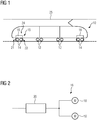
- Figure 1 shows a rail vehicle 10 designed as a multiple unit in a highly schematic side view. It has running axles 12 and driving wheel units designed as driving axles 14, which are driven in a traction mode by means of a drive device 15.
- the drive axles 14 are mounted in engine chassis devices, in particular engine bogies.
- the rail vehicle 10 is designed for high-speed traffic and has a maximum permitted speed in passenger operation of 350 km / h.
- the rail vehicle 10 corresponds to an association of carriages, each of which is designed for the transport of passengers, at least one of the carriages being designed as a railcar with drive axles 14.
- the rail vehicle can be designed as a set comprising a traction vehicle and a set of drive-less passenger coaches coupled to it.
- the drive device 15 has a set of drive units 16, each of which is assigned to a different drive gear device.
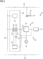
- the drive units 16 have as in FIG Figure 2 shown drive motors 18, which are designed in particular as a three-phase machine and are each provided for driving a different drive axis 14.
- the drive units 16 each further comprise at least one power supply unit 20 which is operatively connected to them.
- This is known from the prior art and has an inverter (not shown in more detail) which, in a traction mode of the drive unit 16, by controlling electronic switching elements - also "valves "called - a power electronics based on a DC voltage generates a variable in voltage and frequency current according to the power to be provided for the or the associated drive motors 18.
- the energy available for this purpose in an assigned DC voltage intermediate circuit is obtained from a high-voltage mains supply 25.
- An energy obtained from this is conducted in a traction mode via a current collector and further electrical conversion devices, not shown, such as in particular a transformer or a voltage converter, a rectifier etc. to the drive device 15.
- the switching elements of the inverters are controlled according to a switching strategy in order to generate a drive torque on the assigned drive axles 14 via the drive motors 18.
- the rail vehicle 10 also has a braking device 21.
- the rail vehicle 10 is braked at least by means of the drive units 16, which each have the function of an electrodynamic brake.
- the drive units 16 therefore each form part of the electrical brake unit 24.
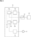
- the brake device 21 has a brake control device 26. This is based on the Figure 3 explained in more detail. In the figure, only one of the drive units 16 is shown, with the following description Application for other drive units 16, not shown, finds.
- the brake control device 26 comprises a brake control unit 28, which is provided to control the power supply unit 20 of the drive unit 16 for a braking operation of the electric brake unit 24 in an active state.
- the brake control unit 28 is provided for controlling the switching elements of the inverter of the power supply unit 20 for this braking operation in accordance with a switching strategy in such a way that a braking torque on the assigned drive axle 14 is generated via an assigned drive motor 18.
- the drive motor 18 acts as a generator, the energy converted into electrical current during the braking process being converted into heat by means of a braking resistor 32.
- the energy can be fed back into the high-voltage network supply 25, used on the vehicle, or stored in a mobile memory.
- the brake control unit 28 is operatively connected to the power supply unit 20.
- the brake control unit 28 has a further interface through which it is operatively connected to a sensor unit 34.
- the sensor unit 34 serves to detect a speed parameter v and a mass parameter m, which represent input parameters for the generation of control signals 44 by the brake control unit 28.
- the brake control device 26 also includes a brake control unit 30, which is designed to control components of the friction brake unit 22. In particular, it controls - via a rail vehicle main air line 38 - when actuating the friction brake unit 22 actuators, by means of which contact between the brake disc is formed Brake components 31 (see also Figure 5 ) and brake pads is manufactured.
- the brake control device 26 in particular its brake control units 28 and 30, is also operatively connected to the rail vehicle control system via interfaces by being connected to a data bus 36 of the rail vehicle 10. Via these further interfaces, further input parameters for the brake control units 28, 30 can be made available, such as, in particular, a parameter which represents the braking effect required by the vehicle driver, by an automatic vehicle control and / or by an emergency braking device.
- the brake control device 26 is supplied with electrical energy via an on-board power supply 40.
- the brake control unit 28 On the basis of the input parameters mentioned above, in a normal braking mode in which it is in an active state, the brake control unit 28 generates control signals 44 which the power supply unit 20 controls in accordance with a specific braking effect to be achieved.
- the brake control unit 28 has at least one computing unit 46 and a storage unit 48, in which software is stored.
- the braking mode switching strategy for the switching elements of the inverter is programmed in this software.
- the electric braking unit 24 has a higher priority than the friction braking unit 22, wherein as large a part of the braking effect as possible is to be generated by the electric braking unit 24 and the friction braking unit 22 if required - in particular in a low speed range - serves to support the electric brake unit 24.
- the brake control unit 28 is assigned a monitoring device 50 of the braking device 21, which is provided to monitor the braking effect achieved or achievable by means of the electric braking unit 24.
- a braking effect parameter in particular a braking torque parameter, is used and compared with a target value.
- the braking action parameter can be detected, for example, by means of an acceleration sensor and / or can be determined by evaluating the speed parameter v. Alternatively or additionally, the braking action parameter can be determined by monitoring the control signals 44 generated by the brake control unit 28.
- an electrical variable - for example an electrical current - of the associated drive motor 18 and / or of the power supply unit 20 can be monitored, in particular evaluated.
- a target braking torque is predominantly, in particular largely provided by means of the electrical braking unit 24.
- the brake control unit 30, which is operatively connected to the rail vehicle main air line 38, controls the friction brake unit 22, the function of which, as described above, includes the support of the electric brake unit 24 - in particular in a low speed range.
- the electrical braking unit 24 is considered to be faulty and the brake control device 26 activates a safety mode of the friction braking unit 22, in which the missing braking torque is compensated, if necessary the entire target braking torque is generated.
- the limitation of the electrical brake unit 24 can be based on a fault in a drive unit 16 and / or a brake control unit 28 assigned to it.
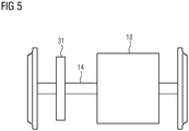
- Figure 4 shows a special embodiment of the brake control device 26.
- it has two brake control units 28a, 28b, which are each provided as described above for controlling an identical power supply unit 20 of the drive device 15 for a braking operation of the electric braking unit 24.
- the monitoring device 50 has two monitoring units 50a and 50b, which are each provided for monitoring a different brake control unit 28a and 28b.
- the brake control units 28a, 28b are each connected to the power supply unit 20 via a switching unit 52.
- This switching unit 52 shown schematically in the figure, can have a mechanical switch or can be implemented as a software solution.
- the electrical braking unit 24 is generally controlled by means of the braking control unit 28a.
- the brake control unit 28b is in an inactive state due to a corresponding position of the switching unit 52.
- a braking operation of the electrical braking unit 24 is monitored as described above by means of the monitoring unit 50a. If, as described above, it is recognized that a target braking torque provided for the electrical braking unit 24 cannot be provided by the latter, the switching unit 52 actuates the switching unit 52, as a result of which the brake control unit 28a is put into an inactive state and the brake control unit 28b is activated becomes.
- the electrical brake unit 24 is then further controlled by means of the brake control unit 28b.
- the brake control unit 28b is assigned a second monitoring unit 50b that is different from the first monitoring unit 50a in terms of software and / or hardware technology. This is provided to monitor the braking effect achieved or achievable by means of the electrical brake unit 24 with the brake control unit 28b. For this purpose - as already described above - a braking effect parameter, in particular a braking torque parameter, recorded or determined and compared with a target value.
- the brake control unit 28b is regarded as faulty and the safety mode of the friction braking unit 22 is activated as described above.
- the brake control units 28a, 28b are designed to be diversely redundant to one another. They are based on different technologies. A technology encompasses the constructive - or hardware-technical - and / or the algorithmic - or software-technical - execution.
- the first brake control unit 28 can be designed in the form of a signal processor, the algorithmic implementation corresponding to a field-oriented control.
- the brake control unit 28b can be embodied as a field programmable gate array (FPGA) or “gate arrangement programmable in the field”, the algorithmic implementation corresponding to a switch-oriented regulation.
- FPGA field programmable gate array
- Figure 5 shows a drive axle 14, the drive motor 18 assigned to it and a brake component 31 of the friction brake unit 22.
- This is designed as a brake disc which is made of a composite material.
- the brake component 31 is designed as a ceramic brake disc made of a C / C-SiC carbon fiber composite material.
- the friction braking unit 22 is relieved of the load by the electric braking unit 24 to such an extent that it does not exceed the corresponding oxidation temperature limit - for the selected material in the range from approximately 300 ° C. to 500 ° C.
- the brake components 31 can master the corresponding overload very well, since they ensure damage-free operation up to temperatures of more than 800 ° C, preferably up to 1300 ° C, ie capable of overloading.
- a rail vehicle is exemplary.
- vehicles are conceivable that are not bound to rails, e.g. a car, a bus or a truck.
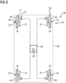
- FIG. 6 shows a highly schematic plan view of a chassis 54 of a motor vehicle 56. This is designed in particular as a passenger car (passenger car), wherein training as a truck (truck) or omnibus is also conceivable.
- An outer contour 58 of motor vehicle 56 is shown in dashed lines and schematically.
- the undercarriage 54 has a set of drive wheel units which are each designed as drivable vehicle wheels 60.
- the vehicle wheels 60 are mechanically independent of one another and in particular form autonomous drivable units.
- the vehicle wheels 60 are each assigned a drive unit 16 'of the drive device 15' of the motor vehicle 56.
- the drive units 16 'each have a drive motor 18' designed as a wheel hub drive.
- the drive units 16 ' also form part of an electric brake unit 24'.
- At least one brake component 31 'of a friction brake unit 22' is also assigned to the vehicle wheels 60.
- the brake components 31 ' are designed as brake disks, which are made of a composite material.
- the electric brake unit 24 'and the friction brake unit 22' are components of a brake device 21 'of the motor vehicle 56, which also control a brake control device 26' comprising a monitoring device for controlling the same 50 '.
- a brake control device 26' comprising a monitoring device for controlling the same 50 '.
- the embodiment of the Figure 6 can also be used in rail vehicles, for example trams.
Claims (16)
- Véhicule ayant un dispositif (21 ; 21') de freinage, qui a au moins- une unité (22 ; 22') de frein à friction, ayant au moins des éléments (31 ; 31') de frein en matériau composite,- une unité (24, 24') électrique de frein, et- un dispositif (26 ; 26') de commande de frein, comprenant un dispositif (50, 50') de contrôle pour contrôler le freinage effectué au moyen de l'unité (24, 24') électrique de frein,dans lequel le dispositif (26, 26') de commande de frein est prévu pour effectuer, dans un mode de freinage normal, une opération de freinage prioritairement au moyen de l'unité (24) électrique de frein, et pour effectuer, dans un mode de sécurité, s'il y a une limitation détectée au moyen du dispositif (50, 50') de contrôle, de l'unité (24, 24') électrique de frein, l'opération de freinage prioritairement au moyen de l'unité (22, 22') de frein à friction, et
dans lequel les éléments (31, 31') de frein de l'unité (22, 22') de frein à friction sont conçus de manière à ne pas dépasser, dans le mode de freinage normal, une température limite d'oxydation du matériau composite et de manière à ce que, dans le mode de sécurité, le matériau composite puisse fonctionner dans une plage de température, qui est au-dessus de la température limite d'oxydation. - Véhicule suivant la revendication 1,
caractérisé par
un dispositif (15, 15') d'entraînement, l'unité (24, 24') électrique de frein ayant au moins une unité (16 ; 16') d'entraînement du dispositif (15, 15') d'entraînement. - Véhicule suivant la revendication 2,
caractérisé en ce que,
à plusieurs roues (60) du véhicule sont affectés, respectivement, a moins l'un éléments (31') de frein de l'unité (22') de frein à friction et une unité (24') d'entraînement du dispositif (15') d'entraînement, l'unité (24') d'entraînement faisant partie de l'unité (24') électrique de frein. - Véhicule suivant l'une des revendications précédentes,
caractérisé en ce que
le dispositif (26) de commande de frein a au moins deux unités (28a, 28b) de commande de frein pour commander l'unité (24) électrique de frein, qui sont constituées en étant redondantes l'une par rapport à l'autre ou redondantes en diversité. - Véhicule suivant l'une des revendications précédentes,
caractérisé en ce que
le dispositif (26) de commande de frein a au moins deux unités (28a, 28b) de commande de frein pour commander l'unité (24) électrique de frein et le dispositif (50) de contrôle comprend au moins deux unités (50a, 50b) de contrôle différentes l'une de l'autre, qui sont associées chacune à une unité (28a, 28b) de commande de frein différente. - Véhicule suivant l'une des revendications précédentes,
caractérisé en ce que
le dispositif (26) de commande de frein est prévu pour, lors d'un effet de freinage, détecté au moyen du dispositif (50) de contrôle, qui est défectueux par rapport à un effet de freinage de consigne, de l'unité (24) électrique de frein, commander l'unité (22) de frein à friction pour une compensation de l'effet de freinage. - Véhicule suivant l'une des revendications précédentes,
caractérisé en ce que
le matériau composite est constitué sous la forme d'un matériau composite à fibre. - Véhicule suivant la revendication 7,
caractérisé en ce que
le matériau composite est constitué sous la forme d'un matériau composite en fibre de carbone. - Véhicule suivant l'une des revendications précédentes, caractérisé en ce que
le matériau composite est un matériau composite céramique. - Véhicule suivant l'une des revendications précédentes,
caractérisé en ce que
le matériau composite a une température limite d'oxydation allant de 300 à 500°C. - Véhicule suivant l'une des revendications précédentes,
caractérisé en ce que
le matériau composite est conçu pour un fonctionnement sans dommage jusqu'à des températures allant de 800 à 1400°C. - Véhicule suivant l'une des revendications précédentes,
caractérisé en ce qu'
il est sous la forme d'un véhicule (56) automobile. - Véhicule suivant l'une des revendications précédentes,
caractérisé en ce qu'
il est constitué sous la forme d'un véhicule (10) ferroviaire. - Véhicule suivant la revendication 13,
caractérisé en ce qu'
il est constitué sous la forme d'une rame automotrice pour le trafic à grande vitesse à une vitesse de fonctionnement maximum d'au moins 350 km/h. - Véhicule suivant l'une des revendications précédentes,
caractérisé en ce que
le mode normal de frein comprend l'exécution d'un freinage de service. - Véhicule suivant l'une des revendications précédentes,
caractérisé en ce que
le mode de sécurité comprend l'exécution d'un freinage à fond.
Priority Applications (1)
| Application Number | Priority Date | Filing Date | Title |
|---|---|---|---|
| PL16805373T PL3371012T3 (pl) | 2015-12-30 | 2016-11-30 | Pojazd z urządzeniem hamującym |
Applications Claiming Priority (2)
| Application Number | Priority Date | Filing Date | Title |
|---|---|---|---|
| DE102015226831.4A DE102015226831A1 (de) | 2015-12-30 | 2015-12-30 | Fahrzeug mit einer Bremseinrichtung |
| PCT/EP2016/079181 WO2017114616A1 (fr) | 2015-12-30 | 2016-11-30 | Véhicule équipé d'un dispositif de freinage |
Publications (2)
| Publication Number | Publication Date |
|---|---|
| EP3371012A1 EP3371012A1 (fr) | 2018-09-12 |
| EP3371012B1 true EP3371012B1 (fr) | 2020-05-27 |
Family
ID=57471851
Family Applications (1)
| Application Number | Title | Priority Date | Filing Date |
|---|---|---|---|
| EP16805373.4A Active EP3371012B1 (fr) | 2015-12-30 | 2016-11-30 | Véhicule équipé d'un dispositif de freinage |
Country Status (9)
| Country | Link |
|---|---|
| US (1) | US10836265B2 (fr) |
| EP (1) | EP3371012B1 (fr) |
| KR (1) | KR102189911B1 (fr) |
| CN (1) | CN108473114B (fr) |
| DE (1) | DE102015226831A1 (fr) |
| ES (1) | ES2812224T3 (fr) |
| PL (1) | PL3371012T3 (fr) |
| RU (1) | RU2701898C1 (fr) |
| WO (1) | WO2017114616A1 (fr) |
Families Citing this family (9)
| Publication number | Priority date | Publication date | Assignee | Title |
|---|---|---|---|---|
| GB2571359A (en) | 2018-02-27 | 2019-08-28 | Airbus Operations Ltd | Brake monitoring |
| DE102018208664A1 (de) * | 2018-05-31 | 2019-12-05 | Siemens Mobility GmbH | Überwachung einer elektrodynamischen Bremse in einem Schienenfahrzeug |
| IT201800007444A1 (it) * | 2018-07-23 | 2020-01-23 | Sistema di frenatura per un convoglio ferroviario. | |
| DE102018212768A1 (de) * | 2018-07-31 | 2020-02-06 | Siemens Aktiengesellschaft | Verfahren zum Erzeugen einer Bewegungsinformation |
| US11427175B2 (en) | 2019-12-16 | 2022-08-30 | Waymo Llc | Vehicle braking systems and methods |
| CN112849170B (zh) * | 2021-02-19 | 2024-01-05 | 安徽万航轨道交通装备有限公司 | 一种铁路机车火车头油电混合驱动装置 |
| WO2023183974A1 (fr) * | 2022-03-29 | 2023-10-05 | Red Automotive Technologies Pty Ltd | Système de commande d'une force appliquée sur une remorque tractée par un véhicule |
| DE102022203764A1 (de) | 2022-04-13 | 2023-10-19 | Knorr-Bremse Systeme für Schienenfahrzeuge GmbH | Bremssystem und Bremsverfahren für Schienenfahrzeuge |
| DE102022203763A1 (de) | 2022-04-13 | 2023-10-19 | Knorr-Bremse Systeme für Schienenfahrzeuge GmbH | Bremssystem und Bremsverfahren für Schienenfahrzeuge |
Family Cites Families (18)
| Publication number | Priority date | Publication date | Assignee | Title |
|---|---|---|---|---|
| DE4423692A1 (de) * | 1994-07-06 | 1996-01-11 | Abb Patent Gmbh | Verfahren zur Überbrückung von Lücken in der Stromversorgung von elektrischen Schienenfahrzeugen |
| US5806636A (en) * | 1995-08-16 | 1998-09-15 | Northrop Grumman Corporation | Brake rotors/drums and brake pads particulary adapted for motorized vehicles |
| JP2001251701A (ja) | 2000-03-06 | 2001-09-14 | Hitachi Ltd | 電気車の制御装置 |
| DE602005017098D1 (de) * | 2004-07-21 | 2009-11-26 | Nissan Motor | Verfahren und Vorrichtung zum Steuern des Drehmoments eines Elektromotors für ein Kraftfahrzeug |
| GB2426756A (en) * | 2005-06-03 | 2006-12-06 | Huntercombe Consultancy Ltd | Porous body containing within its pores a chemically bonded phosphate ceramic |
| ITTO20060735A1 (it) * | 2006-10-13 | 2008-04-14 | St Microelectronics Srl | Sistema e metodo di controllo autoadattativo di un freno elettromeccanico |
| DE102006057065A1 (de) * | 2006-11-29 | 2008-06-05 | Siemens Ag | Verfahren zum Bremsen eines Schienenfahrzeuges |
| GB0701847D0 (en) * | 2007-01-31 | 2007-03-14 | Surface Transforms Plc | Improvements in or relating to brake and clutch discs |
| DE102008024180A1 (de) * | 2007-06-19 | 2008-12-24 | Continental Teves Ag & Co. Ohg | Kombinierte Bremsanlage, insbesondere für Kraftfahrzeuge |
| FR2920356B1 (fr) * | 2007-09-04 | 2012-05-18 | Alstom Transport Sa | Dispositif securitaire de detection d'insufisance de freinage electrique et de commutation sur un frein securitaire. |
| DE102008012957A1 (de) * | 2008-03-06 | 2009-09-10 | Repower Systems Ag | Verfahren zum Betreiben einer Windenergieanlage und Windenergieanlage |
| DE102009051019A1 (de) * | 2009-10-28 | 2011-05-05 | Knorr-Bremse Systeme für Schienenfahrzeuge GmbH | Notbremseinrichtung eines Schienenfahrzeugs |
| DE102011113086B4 (de) * | 2011-09-09 | 2021-03-18 | Knorr-Bremse Systeme für Schienenfahrzeuge GmbH | Bremskrafterfassung für dynamische Bremsen eines Schienenfahrzeugs |
| RU116413U1 (ru) * | 2011-12-09 | 2012-05-27 | Закрытое акционерное общество "Кронид-ЭЛ" | Устройство для автоматического управления электрическим реостатным тормозом электровоза переменного тока |
| US8739938B2 (en) | 2012-02-01 | 2014-06-03 | GM Global Technology Operations LLC | Friction brake with a resistive sensor |
| DE102012203132A1 (de) * | 2012-02-29 | 2013-08-29 | Siemens Aktiengesellschaft | Schienenfahrzeugbremsvorrichtung |
| CN103381798B (zh) * | 2012-05-02 | 2015-07-29 | 中国铁道科学研究院机车车辆研究所 | 轨道交通车辆的电空制动控制装置及其控制方法 |
| DE102013226966A1 (de) | 2013-12-20 | 2015-07-09 | Siemens Aktiengesellschaft | Schienenfahrzeugverband |
-
2015
- 2015-12-30 DE DE102015226831.4A patent/DE102015226831A1/de not_active Withdrawn
-
2016
- 2016-11-30 RU RU2018125436A patent/RU2701898C1/ru active
- 2016-11-30 EP EP16805373.4A patent/EP3371012B1/fr active Active
- 2016-11-30 CN CN201680077302.6A patent/CN108473114B/zh active Active
- 2016-11-30 KR KR1020187020767A patent/KR102189911B1/ko active IP Right Grant
- 2016-11-30 WO PCT/EP2016/079181 patent/WO2017114616A1/fr active Application Filing
- 2016-11-30 US US16/067,743 patent/US10836265B2/en active Active
- 2016-11-30 ES ES16805373T patent/ES2812224T3/es active Active
- 2016-11-30 PL PL16805373T patent/PL3371012T3/pl unknown
Non-Patent Citations (1)
| Title |
|---|
| None * |
Also Published As
| Publication number | Publication date |
|---|---|
| PL3371012T3 (pl) | 2020-09-21 |
| CN108473114A (zh) | 2018-08-31 |
| US20190023151A1 (en) | 2019-01-24 |
| ES2812224T3 (es) | 2021-03-16 |
| US10836265B2 (en) | 2020-11-17 |
| WO2017114616A1 (fr) | 2017-07-06 |
| DE102015226831A1 (de) | 2017-07-06 |
| RU2701898C1 (ru) | 2019-10-02 |
| CN108473114B (zh) | 2020-12-04 |
| KR20180096727A (ko) | 2018-08-29 |
| KR102189911B1 (ko) | 2020-12-11 |
| EP3371012A1 (fr) | 2018-09-12 |
Similar Documents
| Publication | Publication Date | Title |
|---|---|---|
| EP3371012B1 (fr) | Véhicule équipé d'un dispositif de freinage | |
| EP2800672B1 (fr) | Dispositif de freinage de véhicule sur rails | |
| WO2015043715A1 (fr) | Engin de travail automoteur et procédé de freinage d'un tel engin de travail | |
| DE102011110053A1 (de) | Bremsanlage mit Magnetschienenbremseinrichtung | |
| DE102009030816A1 (de) | Vorrichtung und Verfahren zur Regelung einer Fahrdynamik | |
| EP2086788B1 (fr) | Procédé pour faire freiner de manière générative un véhicule à rail comprenant un circuit de freinage de remplacement, passif et sous-jacent, et dispositif permettant la mise en oeuvre du procédé | |
| AT522041A1 (de) | Fahrzeugkomponente | |
| DE102017210750A1 (de) | Bordnetz für ein Schienenfahrzeug, Verfahren zum Betreiben des Bordnetzes und Schienenfahrzeug | |
| WO2006097499A2 (fr) | Frein d'arret destine a des motrices sur rails | |
| DE102020200852A1 (de) | Antriebssystem mit integrierter Wirbelstrombremse | |
| EP3634823B1 (fr) | Dispositif comprenant un moyen de commande d'entraînement, véhicule comprenant un tel dispositif et procédé de fonctionnement d'un moyen de commande d'entraînement | |
| EP3419872B1 (fr) | Procédé et dispositif pour commander ou réguler un dispositif de freinage | |
| DE102007043578A1 (de) | Verfahren und Vorrichtung zur Rückgewinnung von kinetischer Energie eines bewegten Fahrzeuges zur Versorgung sicherheitsrelevanter Fahrzeugfunktionen | |
| EP3353035A1 (fr) | Procédé de fonctionnement d'un véhicule ferroviaire le long d'une ligne de chemin de fer | |
| DE102022203766B4 (de) | Bremssystem und Bremsverfahren für Schienenfahrzeuge | |
| WO2023198404A1 (fr) | Système de freinage et procédé de freinage pour véhicules ferroviaires | |
| WO2023198390A1 (fr) | Système de freinage et procédé de freinage pour véhicule ferroviaire | |
| WO2023198388A1 (fr) | Système de freinage et procédé de freinage pour un véhicule ferroviaire | |
| DE102022123719A1 (de) | Kraftfahrzeugantriebsstrang und Verfahren zum Steuern eines Bremsbetriebs eines Kraftfahrzeugs | |
| WO2023198423A1 (fr) | Système de freinage et procédé de freinage pour un véhicule ferroviaire | |
| DE102021205120A1 (de) | Antriebseinheit für ein elektrisches Antriebssystem, elektrisches Antriebssystem sowie Verfahren zum Betreiben einer Antriebseinheit eines elektrischen Antriebssystems | |
| WO2023006287A1 (fr) | Procédé de freinage d'une motocyclette et motocyclette électrique | |
| EP2948352A1 (fr) | Dispositif permettant de commander un organe d'entraînement d'un véhicule ferroviaire | |
| DE102022103806A1 (de) | Bremssystemaufbau und Fahrzeug mit einem Bremssystemaufbau | |
| DE102019217610A1 (de) | Verfahren zum Betrieb eines aus einem Zugfahrzeug und wenigstens einem Anhänger bestehenden Gespanns |
Legal Events
| Date | Code | Title | Description |
|---|---|---|---|
| STAA | Information on the status of an ep patent application or granted ep patent |
Free format text: STATUS: UNKNOWN |
|
| STAA | Information on the status of an ep patent application or granted ep patent |
Free format text: STATUS: THE INTERNATIONAL PUBLICATION HAS BEEN MADE |
|
| PUAI | Public reference made under article 153(3) epc to a published international application that has entered the european phase |
Free format text: ORIGINAL CODE: 0009012 |
|
| STAA | Information on the status of an ep patent application or granted ep patent |
Free format text: STATUS: REQUEST FOR EXAMINATION WAS MADE |
|
| 17P | Request for examination filed |
Effective date: 20180608 |
|
| AK | Designated contracting states |
Kind code of ref document: A1 Designated state(s): AL AT BE BG CH CY CZ DE DK EE ES FI FR GB GR HR HU IE IS IT LI LT LU LV MC MK MT NL NO PL PT RO RS SE SI SK SM TR |
|
| AX | Request for extension of the european patent |
Extension state: BA ME |
|
| RAP1 | Party data changed (applicant data changed or rights of an application transferred) |
Owner name: SIEMENS MOBILITY GMBH |
|
| DAV | Request for validation of the european patent (deleted) | ||
| DAX | Request for extension of the european patent (deleted) | ||
| GRAP | Despatch of communication of intention to grant a patent |
Free format text: ORIGINAL CODE: EPIDOSNIGR1 |
|
| STAA | Information on the status of an ep patent application or granted ep patent |
Free format text: STATUS: GRANT OF PATENT IS INTENDED |
|
| INTG | Intention to grant announced |
Effective date: 20200117 |
|
| GRAS | Grant fee paid |
Free format text: ORIGINAL CODE: EPIDOSNIGR3 |
|
| GRAA | (expected) grant |
Free format text: ORIGINAL CODE: 0009210 |
|
| STAA | Information on the status of an ep patent application or granted ep patent |
Free format text: STATUS: THE PATENT HAS BEEN GRANTED |
|
| AK | Designated contracting states |
Kind code of ref document: B1 Designated state(s): AL AT BE BG CH CY CZ DE DK EE ES FI FR GB GR HR HU IE IS IT LI LT LU LV MC MK MT NL NO PL PT RO RS SE SI SK SM TR |
|
| REG | Reference to a national code |
Ref country code: GB Ref legal event code: FG4D Free format text: NOT ENGLISH |
|
| REG | Reference to a national code |
Ref country code: CH Ref legal event code: EP |
|
| REG | Reference to a national code |
Ref country code: AT Ref legal event code: REF Ref document number: 1274251 Country of ref document: AT Kind code of ref document: T Effective date: 20200615 |
|
| REG | Reference to a national code |
Ref country code: DE Ref legal event code: R096 Ref document number: 502016010080 Country of ref document: DE |
|
| REG | Reference to a national code |
Ref country code: LT Ref legal event code: MG4D |
|
| PG25 | Lapsed in a contracting state [announced via postgrant information from national office to epo] |
Ref country code: SE Free format text: LAPSE BECAUSE OF FAILURE TO SUBMIT A TRANSLATION OF THE DESCRIPTION OR TO PAY THE FEE WITHIN THE PRESCRIBED TIME-LIMIT Effective date: 20200527 Ref country code: FI Free format text: LAPSE BECAUSE OF FAILURE TO SUBMIT A TRANSLATION OF THE DESCRIPTION OR TO PAY THE FEE WITHIN THE PRESCRIBED TIME-LIMIT Effective date: 20200527 Ref country code: PT Free format text: LAPSE BECAUSE OF FAILURE TO SUBMIT A TRANSLATION OF THE DESCRIPTION OR TO PAY THE FEE WITHIN THE PRESCRIBED TIME-LIMIT Effective date: 20200928 Ref country code: IS Free format text: LAPSE BECAUSE OF FAILURE TO SUBMIT A TRANSLATION OF THE DESCRIPTION OR TO PAY THE FEE WITHIN THE PRESCRIBED TIME-LIMIT Effective date: 20200927 Ref country code: NO Free format text: LAPSE BECAUSE OF FAILURE TO SUBMIT A TRANSLATION OF THE DESCRIPTION OR TO PAY THE FEE WITHIN THE PRESCRIBED TIME-LIMIT Effective date: 20200827 Ref country code: GR Free format text: LAPSE BECAUSE OF FAILURE TO SUBMIT A TRANSLATION OF THE DESCRIPTION OR TO PAY THE FEE WITHIN THE PRESCRIBED TIME-LIMIT Effective date: 20200828 Ref country code: LT Free format text: LAPSE BECAUSE OF FAILURE TO SUBMIT A TRANSLATION OF THE DESCRIPTION OR TO PAY THE FEE WITHIN THE PRESCRIBED TIME-LIMIT Effective date: 20200527 |
|
| REG | Reference to a national code |
Ref country code: NL Ref legal event code: MP Effective date: 20200527 |
|
| PG25 | Lapsed in a contracting state [announced via postgrant information from national office to epo] |
Ref country code: LV Free format text: LAPSE BECAUSE OF FAILURE TO SUBMIT A TRANSLATION OF THE DESCRIPTION OR TO PAY THE FEE WITHIN THE PRESCRIBED TIME-LIMIT Effective date: 20200527 Ref country code: RS Free format text: LAPSE BECAUSE OF FAILURE TO SUBMIT A TRANSLATION OF THE DESCRIPTION OR TO PAY THE FEE WITHIN THE PRESCRIBED TIME-LIMIT Effective date: 20200527 Ref country code: BG Free format text: LAPSE BECAUSE OF FAILURE TO SUBMIT A TRANSLATION OF THE DESCRIPTION OR TO PAY THE FEE WITHIN THE PRESCRIBED TIME-LIMIT Effective date: 20200827 Ref country code: HR Free format text: LAPSE BECAUSE OF FAILURE TO SUBMIT A TRANSLATION OF THE DESCRIPTION OR TO PAY THE FEE WITHIN THE PRESCRIBED TIME-LIMIT Effective date: 20200527 |
|
| PG25 | Lapsed in a contracting state [announced via postgrant information from national office to epo] |
Ref country code: NL Free format text: LAPSE BECAUSE OF FAILURE TO SUBMIT A TRANSLATION OF THE DESCRIPTION OR TO PAY THE FEE WITHIN THE PRESCRIBED TIME-LIMIT Effective date: 20200527 Ref country code: AL Free format text: LAPSE BECAUSE OF FAILURE TO SUBMIT A TRANSLATION OF THE DESCRIPTION OR TO PAY THE FEE WITHIN THE PRESCRIBED TIME-LIMIT Effective date: 20200527 |
|
| PG25 | Lapsed in a contracting state [announced via postgrant information from national office to epo] |
Ref country code: RO Free format text: LAPSE BECAUSE OF FAILURE TO SUBMIT A TRANSLATION OF THE DESCRIPTION OR TO PAY THE FEE WITHIN THE PRESCRIBED TIME-LIMIT Effective date: 20200527 Ref country code: CZ Free format text: LAPSE BECAUSE OF FAILURE TO SUBMIT A TRANSLATION OF THE DESCRIPTION OR TO PAY THE FEE WITHIN THE PRESCRIBED TIME-LIMIT Effective date: 20200527 Ref country code: EE Free format text: LAPSE BECAUSE OF FAILURE TO SUBMIT A TRANSLATION OF THE DESCRIPTION OR TO PAY THE FEE WITHIN THE PRESCRIBED TIME-LIMIT Effective date: 20200527 Ref country code: SM Free format text: LAPSE BECAUSE OF FAILURE TO SUBMIT A TRANSLATION OF THE DESCRIPTION OR TO PAY THE FEE WITHIN THE PRESCRIBED TIME-LIMIT Effective date: 20200527 Ref country code: DK Free format text: LAPSE BECAUSE OF FAILURE TO SUBMIT A TRANSLATION OF THE DESCRIPTION OR TO PAY THE FEE WITHIN THE PRESCRIBED TIME-LIMIT Effective date: 20200527 |
|
| PG25 | Lapsed in a contracting state [announced via postgrant information from national office to epo] |
Ref country code: SK Free format text: LAPSE BECAUSE OF FAILURE TO SUBMIT A TRANSLATION OF THE DESCRIPTION OR TO PAY THE FEE WITHIN THE PRESCRIBED TIME-LIMIT Effective date: 20200527 |
|
| REG | Reference to a national code |
Ref country code: DE Ref legal event code: R097 Ref document number: 502016010080 Country of ref document: DE |
|
| REG | Reference to a national code |
Ref country code: CH Ref legal event code: NV Representative=s name: SIEMENS SCHWEIZ AG, CH |
|
| REG | Reference to a national code |
Ref country code: ES Ref legal event code: FG2A Ref document number: 2812224 Country of ref document: ES Kind code of ref document: T3 Effective date: 20210316 |
|
| PLBE | No opposition filed within time limit |
Free format text: ORIGINAL CODE: 0009261 |
|
| STAA | Information on the status of an ep patent application or granted ep patent |
Free format text: STATUS: NO OPPOSITION FILED WITHIN TIME LIMIT |
|
| 26N | No opposition filed |
Effective date: 20210302 |
|
| PG25 | Lapsed in a contracting state [announced via postgrant information from national office to epo] |
Ref country code: SI Free format text: LAPSE BECAUSE OF FAILURE TO SUBMIT A TRANSLATION OF THE DESCRIPTION OR TO PAY THE FEE WITHIN THE PRESCRIBED TIME-LIMIT Effective date: 20200527 |
|
| PG25 | Lapsed in a contracting state [announced via postgrant information from national office to epo] |
Ref country code: MC Free format text: LAPSE BECAUSE OF FAILURE TO SUBMIT A TRANSLATION OF THE DESCRIPTION OR TO PAY THE FEE WITHIN THE PRESCRIBED TIME-LIMIT Effective date: 20200527 |
|
| REG | Reference to a national code |
Ref country code: CH Ref legal event code: PL |
|
| PG25 | Lapsed in a contracting state [announced via postgrant information from national office to epo] |
Ref country code: LU Free format text: LAPSE BECAUSE OF NON-PAYMENT OF DUE FEES Effective date: 20201130 |
|
| REG | Reference to a national code |
Ref country code: BE Ref legal event code: MM Effective date: 20201130 |
|
| PG25 | Lapsed in a contracting state [announced via postgrant information from national office to epo] |
Ref country code: CH Free format text: LAPSE BECAUSE OF NON-PAYMENT OF DUE FEES Effective date: 20201130 Ref country code: LI Free format text: LAPSE BECAUSE OF NON-PAYMENT OF DUE FEES Effective date: 20201130 |
|
| REG | Reference to a national code |
Ref country code: IE Ref legal event code: MM4A |
|
| PG25 | Lapsed in a contracting state [announced via postgrant information from national office to epo] |
Ref country code: IE Free format text: LAPSE BECAUSE OF NON-PAYMENT OF DUE FEES Effective date: 20201130 |
|
| PG25 | Lapsed in a contracting state [announced via postgrant information from national office to epo] |
Ref country code: TR Free format text: LAPSE BECAUSE OF FAILURE TO SUBMIT A TRANSLATION OF THE DESCRIPTION OR TO PAY THE FEE WITHIN THE PRESCRIBED TIME-LIMIT Effective date: 20200527 Ref country code: MT Free format text: LAPSE BECAUSE OF FAILURE TO SUBMIT A TRANSLATION OF THE DESCRIPTION OR TO PAY THE FEE WITHIN THE PRESCRIBED TIME-LIMIT Effective date: 20200527 Ref country code: CY Free format text: LAPSE BECAUSE OF FAILURE TO SUBMIT A TRANSLATION OF THE DESCRIPTION OR TO PAY THE FEE WITHIN THE PRESCRIBED TIME-LIMIT Effective date: 20200527 |
|
| PG25 | Lapsed in a contracting state [announced via postgrant information from national office to epo] |
Ref country code: MK Free format text: LAPSE BECAUSE OF FAILURE TO SUBMIT A TRANSLATION OF THE DESCRIPTION OR TO PAY THE FEE WITHIN THE PRESCRIBED TIME-LIMIT Effective date: 20200527 |
|
| PG25 | Lapsed in a contracting state [announced via postgrant information from national office to epo] |
Ref country code: BE Free format text: LAPSE BECAUSE OF NON-PAYMENT OF DUE FEES Effective date: 20201130 |
|
| REG | Reference to a national code |
Ref country code: AT Ref legal event code: MM01 Ref document number: 1274251 Country of ref document: AT Kind code of ref document: T Effective date: 20211130 |
|
| PG25 | Lapsed in a contracting state [announced via postgrant information from national office to epo] |
Ref country code: AT Free format text: LAPSE BECAUSE OF NON-PAYMENT OF DUE FEES Effective date: 20211130 |
|
| PGFP | Annual fee paid to national office [announced via postgrant information from national office to epo] |
Ref country code: PL Payment date: 20221118 Year of fee payment: 7 |
|
| PGFP | Annual fee paid to national office [announced via postgrant information from national office to epo] |
Ref country code: ES Payment date: 20230220 Year of fee payment: 7 |
|
| PGFP | Annual fee paid to national office [announced via postgrant information from national office to epo] |
Ref country code: GB Payment date: 20231204 Year of fee payment: 8 |
|
| PGFP | Annual fee paid to national office [announced via postgrant information from national office to epo] |
Ref country code: IT Payment date: 20231122 Year of fee payment: 8 Ref country code: FR Payment date: 20231114 Year of fee payment: 8 |
|
| PGFP | Annual fee paid to national office [announced via postgrant information from national office to epo] |
Ref country code: ES Payment date: 20240221 Year of fee payment: 8 |
|
| PGFP | Annual fee paid to national office [announced via postgrant information from national office to epo] |
Ref country code: DE Payment date: 20240119 Year of fee payment: 8 |