EP3370867B1 - Sample preparation device - Google Patents
Sample preparation device Download PDFInfo
- Publication number
- EP3370867B1 EP3370867B1 EP16790578.5A EP16790578A EP3370867B1 EP 3370867 B1 EP3370867 B1 EP 3370867B1 EP 16790578 A EP16790578 A EP 16790578A EP 3370867 B1 EP3370867 B1 EP 3370867B1
- Authority
- EP
- European Patent Office
- Prior art keywords
- sample
- chamber
- metering
- nucleic acid
- liquid
- Prior art date
- Legal status (The legal status is an assumption and is not a legal conclusion. Google has not performed a legal analysis and makes no representation as to the accuracy of the status listed.)
- Active
Links
- 238000002360 preparation method Methods 0.000 title description 21
- 239000012530 fluid Substances 0.000 claims description 85
- 230000003321 amplification Effects 0.000 claims description 77
- 238000003199 nucleic acid amplification method Methods 0.000 claims description 77
- 102000039446 nucleic acids Human genes 0.000 claims description 75
- 108020004707 nucleic acids Proteins 0.000 claims description 75
- 150000007523 nucleic acids Chemical class 0.000 claims description 75
- 239000007788 liquid Substances 0.000 claims description 73
- KWYUFKZDYYNOTN-UHFFFAOYSA-M Potassium hydroxide Chemical compound [OH-].[K+] KWYUFKZDYYNOTN-UHFFFAOYSA-M 0.000 claims description 51
- 239000003795 chemical substances by application Substances 0.000 claims description 49
- 238000006243 chemical reaction Methods 0.000 claims description 43
- HEMHJVSKTPXQMS-UHFFFAOYSA-M Sodium hydroxide Chemical compound [OH-].[Na+] HEMHJVSKTPXQMS-UHFFFAOYSA-M 0.000 claims description 39
- 238000001542 size-exclusion chromatography Methods 0.000 claims description 33
- 238000000926 separation method Methods 0.000 claims description 32
- 238000004587 chromatography analysis Methods 0.000 claims description 31
- 238000004891 communication Methods 0.000 claims description 28
- 230000002101 lytic effect Effects 0.000 claims description 28
- 238000012546 transfer Methods 0.000 claims description 23
- 230000002401 inhibitory effect Effects 0.000 claims description 15
- 239000000872 buffer Substances 0.000 claims description 14
- 239000007850 fluorescent dye Substances 0.000 claims description 13
- 238000012545 processing Methods 0.000 claims description 13
- 238000012360 testing method Methods 0.000 claims description 12
- 238000000034 method Methods 0.000 claims description 10
- 239000004094 surface-active agent Substances 0.000 claims description 10
- 239000003153 chemical reaction reagent Substances 0.000 claims description 8
- UEGPKNKPLBYCNK-UHFFFAOYSA-L magnesium acetate Chemical compound [Mg+2].CC([O-])=O.CC([O-])=O UEGPKNKPLBYCNK-UHFFFAOYSA-L 0.000 claims description 7
- 239000011654 magnesium acetate Substances 0.000 claims description 7
- 229940069446 magnesium acetate Drugs 0.000 claims description 7
- 235000011285 magnesium acetate Nutrition 0.000 claims description 7
- 239000008188 pellet Substances 0.000 claims description 7
- LZZYPRNAOMGNLH-UHFFFAOYSA-M Cetrimonium bromide Chemical compound [Br-].CCCCCCCCCCCCCCCC[N+](C)(C)C LZZYPRNAOMGNLH-UHFFFAOYSA-M 0.000 claims description 5
- DBMJMQXJHONAFJ-UHFFFAOYSA-M Sodium laurylsulphate Chemical compound [Na+].CCCCCCCCCCCCOS([O-])(=O)=O DBMJMQXJHONAFJ-UHFFFAOYSA-M 0.000 claims description 5
- 239000000463 material Substances 0.000 claims description 5
- 238000012544 monitoring process Methods 0.000 claims description 5
- 235000019333 sodium laurylsulphate Nutrition 0.000 claims description 5
- 239000007864 aqueous solution Substances 0.000 claims description 3
- 238000003556 assay Methods 0.000 description 17
- 239000000499 gel Substances 0.000 description 11
- 239000002245 particle Substances 0.000 description 11
- 238000001514 detection method Methods 0.000 description 8
- 239000000243 solution Substances 0.000 description 7
- 102000018120 Recombinases Human genes 0.000 description 6
- 108010091086 Recombinases Proteins 0.000 description 6
- 238000001641 gel filtration chromatography Methods 0.000 description 5
- ZKHQWZAMYRWXGA-KQYNXXCUSA-J ATP(4-) Chemical class C1=NC=2C(N)=NC=NC=2N1[C@@H]1O[C@H](COP([O-])(=O)OP([O-])(=O)OP([O-])([O-])=O)[C@@H](O)[C@H]1O ZKHQWZAMYRWXGA-KQYNXXCUSA-J 0.000 description 4
- 239000002202 Polyethylene glycol Substances 0.000 description 4
- 238000001042 affinity chromatography Methods 0.000 description 4
- 230000009089 cytolysis Effects 0.000 description 4
- 238000002523 gelfiltration Methods 0.000 description 4
- 238000004255 ion exchange chromatography Methods 0.000 description 4
- 229920001223 polyethylene glycol Polymers 0.000 description 4
- 229920000136 polysorbate Polymers 0.000 description 4
- 238000004366 reverse phase liquid chromatography Methods 0.000 description 4
- 239000000725 suspension Substances 0.000 description 4
- 229920002307 Dextran Polymers 0.000 description 3
- 230000005526 G1 to G0 transition Effects 0.000 description 3
- 238000011109 contamination Methods 0.000 description 3
- 238000013016 damping Methods 0.000 description 3
- 230000000994 depressogenic effect Effects 0.000 description 3
- 238000011065 in-situ storage Methods 0.000 description 3
- 239000006166 lysate Substances 0.000 description 3
- 239000011159 matrix material Substances 0.000 description 3
- GPRLSGONYQIRFK-MNYXATJNSA-N triton Chemical compound [3H+] GPRLSGONYQIRFK-MNYXATJNSA-N 0.000 description 3
- -1 urine Substances 0.000 description 3
- ZKHQWZAMYRWXGA-UHFFFAOYSA-N Adenosine triphosphate Natural products C1=NC=2C(N)=NC=NC=2N1C1OC(COP(O)(=O)OP(O)(=O)OP(O)(O)=O)C(O)C1O ZKHQWZAMYRWXGA-UHFFFAOYSA-N 0.000 description 2
- 235000014469 Bacillus subtilis Nutrition 0.000 description 2
- BRLQWZUYTZBJKN-UHFFFAOYSA-N Epichlorohydrin Chemical compound ClCC1CO1 BRLQWZUYTZBJKN-UHFFFAOYSA-N 0.000 description 2
- 108010014594 Heterogeneous Nuclear Ribonucleoprotein A1 Proteins 0.000 description 2
- 239000004372 Polyvinyl alcohol Substances 0.000 description 2
- 238000013019 agitation Methods 0.000 description 2
- 238000005571 anion exchange chromatography Methods 0.000 description 2
- 230000033228 biological regulation Effects 0.000 description 2
- 210000004369 blood Anatomy 0.000 description 2
- 239000008280 blood Substances 0.000 description 2
- 238000005277 cation exchange chromatography Methods 0.000 description 2
- 150000001768 cations Chemical class 0.000 description 2
- 210000001175 cerebrospinal fluid Anatomy 0.000 description 2
- 238000002405 diagnostic procedure Methods 0.000 description 2
- 239000006185 dispersion Substances 0.000 description 2
- 238000006073 displacement reaction Methods 0.000 description 2
- 230000000694 effects Effects 0.000 description 2
- 238000005194 fractionation Methods 0.000 description 2
- 102000034238 globular proteins Human genes 0.000 description 2
- 108091005896 globular proteins Proteins 0.000 description 2
- 230000002452 interceptive effect Effects 0.000 description 2
- 230000003834 intracellular effect Effects 0.000 description 2
- 238000004519 manufacturing process Methods 0.000 description 2
- 239000012528 membrane Substances 0.000 description 2
- 239000000203 mixture Substances 0.000 description 2
- 230000003287 optical effect Effects 0.000 description 2
- 210000002381 plasma Anatomy 0.000 description 2
- 229920002451 polyvinyl alcohol Polymers 0.000 description 2
- 235000019422 polyvinyl alcohol Nutrition 0.000 description 2
- 108090000765 processed proteins & peptides Proteins 0.000 description 2
- 102000004196 processed proteins & peptides Human genes 0.000 description 2
- 210000003296 saliva Anatomy 0.000 description 2
- 238000007789 sealing Methods 0.000 description 2
- 210000002966 serum Anatomy 0.000 description 2
- 238000003860 storage Methods 0.000 description 2
- 239000000758 substrate Substances 0.000 description 2
- 210000001138 tear Anatomy 0.000 description 2
- 210000002700 urine Anatomy 0.000 description 2
- 230000000007 visual effect Effects 0.000 description 2
- OAKPWEUQDVLTCN-NKWVEPMBSA-N 2',3'-Dideoxyadenosine-5-triphosphate Chemical compound C1=NC=2C(N)=NC=NC=2N1[C@H]1CC[C@@H](CO[P@@](O)(=O)O[P@](O)(=O)OP(O)(O)=O)O1 OAKPWEUQDVLTCN-NKWVEPMBSA-N 0.000 description 1
- 102000004594 DNA Polymerase I Human genes 0.000 description 1
- 108010017826 DNA Polymerase I Proteins 0.000 description 1
- 102000016928 DNA-directed DNA polymerase Human genes 0.000 description 1
- 108010014303 DNA-directed DNA polymerase Proteins 0.000 description 1
- 101800001466 Envelope glycoprotein E1 Proteins 0.000 description 1
- 102000004190 Enzymes Human genes 0.000 description 1
- 108090000790 Enzymes Proteins 0.000 description 1
- 241000588724 Escherichia coli Species 0.000 description 1
- 229920001917 Ficoll Polymers 0.000 description 1
- 241000193385 Geobacillus stearothermophilus Species 0.000 description 1
- 238000007397 LAMP assay Methods 0.000 description 1
- 229920002534 Polyethylene Glycol 1450 Polymers 0.000 description 1
- 229920002560 Polyethylene Glycol 3000 Polymers 0.000 description 1
- 229920002594 Polyethylene Glycol 8000 Polymers 0.000 description 1
- 102000001218 Rec A Recombinases Human genes 0.000 description 1
- 108010055016 Rec A Recombinases Proteins 0.000 description 1
- 229920005654 Sephadex Polymers 0.000 description 1
- 239000012507 Sephadex™ Substances 0.000 description 1
- 101800001690 Transmembrane protein gp41 Proteins 0.000 description 1
- 239000007983 Tris buffer Substances 0.000 description 1
- NLTUCYMLOPLUHL-KQYNXXCUSA-N adenosine 5'-[gamma-thio]triphosphate Chemical compound C1=NC=2C(N)=NC=NC=2N1[C@@H]1O[C@H](COP(O)(=O)OP(O)(=O)OP(O)(O)=S)[C@@H](O)[C@H]1O NLTUCYMLOPLUHL-KQYNXXCUSA-N 0.000 description 1
- TTWYZDPBDWHJOR-IDIVVRGQSA-L adenosine triphosphate disodium Chemical compound [Na+].[Na+].C1=NC=2C(N)=NC=NC=2N1[C@@H]1O[C@H](COP(O)(=O)OP(O)(=O)OP([O-])([O-])=O)[C@@H](O)[C@H]1O TTWYZDPBDWHJOR-IDIVVRGQSA-L 0.000 description 1
- 230000000712 assembly Effects 0.000 description 1
- 238000000429 assembly Methods 0.000 description 1
- 239000013060 biological fluid Substances 0.000 description 1
- 239000006172 buffering agent Substances 0.000 description 1
- 210000004027 cell Anatomy 0.000 description 1
- 230000006037 cell lysis Effects 0.000 description 1
- 230000001413 cellular effect Effects 0.000 description 1
- 239000012504 chromatography matrix Substances 0.000 description 1
- 239000012539 chromatography resin Substances 0.000 description 1
- 230000008602 contraction Effects 0.000 description 1
- SUYVUBYJARFZHO-RRKCRQDMSA-N dATP Chemical compound C1=NC=2C(N)=NC=NC=2N1[C@H]1C[C@H](O)[C@@H](COP(O)(=O)OP(O)(=O)OP(O)(O)=O)O1 SUYVUBYJARFZHO-RRKCRQDMSA-N 0.000 description 1
- SUYVUBYJARFZHO-UHFFFAOYSA-N dATP Natural products C1=NC=2C(N)=NC=NC=2N1C1CC(O)C(COP(O)(=O)OP(O)(=O)OP(O)(O)=O)O1 SUYVUBYJARFZHO-UHFFFAOYSA-N 0.000 description 1
- RGWHQCVHVJXOKC-SHYZEUOFSA-J dCTP(4-) Chemical compound O=C1N=C(N)C=CN1[C@@H]1O[C@H](COP([O-])(=O)OP([O-])(=O)OP([O-])([O-])=O)[C@@H](O)C1 RGWHQCVHVJXOKC-SHYZEUOFSA-J 0.000 description 1
- HAAZLUGHYHWQIW-KVQBGUIXSA-N dGTP Chemical compound C1=NC=2C(=O)NC(N)=NC=2N1[C@H]1C[C@H](O)[C@@H](COP(O)(=O)OP(O)(=O)OP(O)(O)=O)O1 HAAZLUGHYHWQIW-KVQBGUIXSA-N 0.000 description 1
- NHVNXKFIZYSCEB-XLPZGREQSA-N dTTP Chemical compound O=C1NC(=O)C(C)=CN1[C@@H]1O[C@H](COP(O)(=O)OP(O)(=O)OP(O)(O)=O)[C@@H](O)C1 NHVNXKFIZYSCEB-XLPZGREQSA-N 0.000 description 1
- 230000003247 decreasing effect Effects 0.000 description 1
- 210000003811 finger Anatomy 0.000 description 1
- 238000003018 immunoassay Methods 0.000 description 1
- 238000001746 injection moulding Methods 0.000 description 1
- 238000003780 insertion Methods 0.000 description 1
- 230000037431 insertion Effects 0.000 description 1
- 150000002632 lipids Chemical class 0.000 description 1
- 238000004811 liquid chromatography Methods 0.000 description 1
- 239000002991 molded plastic Substances 0.000 description 1
- 230000037361 pathway Effects 0.000 description 1
- 239000008363 phosphate buffer Substances 0.000 description 1
- 238000003752 polymerase chain reaction Methods 0.000 description 1
- 230000001681 protective effect Effects 0.000 description 1
- 102000004169 proteins and genes Human genes 0.000 description 1
- 108090000623 proteins and genes Proteins 0.000 description 1
- 238000005086 pumping Methods 0.000 description 1
- 230000002829 reductive effect Effects 0.000 description 1
- 230000002441 reversible effect Effects 0.000 description 1
- 150000003839 salts Chemical class 0.000 description 1
- 210000004243 sweat Anatomy 0.000 description 1
- 210000003813 thumb Anatomy 0.000 description 1
- LENZDBCJOHFCAS-UHFFFAOYSA-N tris Chemical compound OCC(N)(CO)CO LENZDBCJOHFCAS-UHFFFAOYSA-N 0.000 description 1
- PIEPQKCYPFFYMG-UHFFFAOYSA-N tris acetate Chemical compound CC(O)=O.OCC(N)(CO)CO PIEPQKCYPFFYMG-UHFFFAOYSA-N 0.000 description 1
- 241001515965 unidentified phage Species 0.000 description 1
Images


Classifications
-
- B—PERFORMING OPERATIONS; TRANSPORTING
- B01—PHYSICAL OR CHEMICAL PROCESSES OR APPARATUS IN GENERAL
- B01D—SEPARATION
- B01D15/00—Separating processes involving the treatment of liquids with solid sorbents; Apparatus therefor
- B01D15/08—Selective adsorption, e.g. chromatography
- B01D15/10—Selective adsorption, e.g. chromatography characterised by constructional or operational features
- B01D15/12—Selective adsorption, e.g. chromatography characterised by constructional or operational features relating to the preparation of the feed
-
- G—PHYSICS
- G01—MEASURING; TESTING
- G01N—INVESTIGATING OR ANALYSING MATERIALS BY DETERMINING THEIR CHEMICAL OR PHYSICAL PROPERTIES
- G01N30/00—Investigating or analysing materials by separation into components using adsorption, absorption or similar phenomena or using ion-exchange, e.g. chromatography or field flow fractionation
- G01N30/02—Column chromatography
- G01N30/04—Preparation or injection of sample to be analysed
- G01N30/06—Preparation
-
- B—PERFORMING OPERATIONS; TRANSPORTING
- B01—PHYSICAL OR CHEMICAL PROCESSES OR APPARATUS IN GENERAL
- B01D—SEPARATION
- B01D15/00—Separating processes involving the treatment of liquids with solid sorbents; Apparatus therefor
- B01D15/08—Selective adsorption, e.g. chromatography
- B01D15/26—Selective adsorption, e.g. chromatography characterised by the separation mechanism
- B01D15/34—Size selective separation, e.g. size exclusion chromatography, gel filtration, permeation
-
- B—PERFORMING OPERATIONS; TRANSPORTING
- B01—PHYSICAL OR CHEMICAL PROCESSES OR APPARATUS IN GENERAL
- B01L—CHEMICAL OR PHYSICAL LABORATORY APPARATUS FOR GENERAL USE
- B01L3/00—Containers or dishes for laboratory use, e.g. laboratory glassware; Droppers
- B01L3/02—Burettes; Pipettes
- B01L3/021—Pipettes, i.e. with only one conduit for withdrawing and redistributing liquids
- B01L3/0217—Pipettes, i.e. with only one conduit for withdrawing and redistributing liquids of the plunger pump type
-
- B—PERFORMING OPERATIONS; TRANSPORTING
- B01—PHYSICAL OR CHEMICAL PROCESSES OR APPARATUS IN GENERAL
- B01L—CHEMICAL OR PHYSICAL LABORATORY APPARATUS FOR GENERAL USE
- B01L3/00—Containers or dishes for laboratory use, e.g. laboratory glassware; Droppers
- B01L3/02—Burettes; Pipettes
- B01L3/0289—Apparatus for withdrawing or distributing predetermined quantities of fluid
- B01L3/0293—Apparatus for withdrawing or distributing predetermined quantities of fluid for liquids
-
- B—PERFORMING OPERATIONS; TRANSPORTING
- B01—PHYSICAL OR CHEMICAL PROCESSES OR APPARATUS IN GENERAL
- B01L—CHEMICAL OR PHYSICAL LABORATORY APPARATUS FOR GENERAL USE
- B01L3/00—Containers or dishes for laboratory use, e.g. laboratory glassware; Droppers
- B01L3/50—Containers for the purpose of retaining a material to be analysed, e.g. test tubes
- B01L3/502—Containers for the purpose of retaining a material to be analysed, e.g. test tubes with fluid transport, e.g. in multi-compartment structures
-
- B—PERFORMING OPERATIONS; TRANSPORTING
- B01—PHYSICAL OR CHEMICAL PROCESSES OR APPARATUS IN GENERAL
- B01L—CHEMICAL OR PHYSICAL LABORATORY APPARATUS FOR GENERAL USE
- B01L3/00—Containers or dishes for laboratory use, e.g. laboratory glassware; Droppers
- B01L3/56—Labware specially adapted for transferring fluids
- B01L3/567—Valves, taps or stop-cocks
-
- B—PERFORMING OPERATIONS; TRANSPORTING
- B01—PHYSICAL OR CHEMICAL PROCESSES OR APPARATUS IN GENERAL
- B01L—CHEMICAL OR PHYSICAL LABORATORY APPARATUS FOR GENERAL USE
- B01L7/00—Heating or cooling apparatus; Heat insulating devices
- B01L7/52—Heating or cooling apparatus; Heat insulating devices with provision for submitting samples to a predetermined sequence of different temperatures, e.g. for treating nucleic acid samples
-
- C—CHEMISTRY; METALLURGY
- C12—BIOCHEMISTRY; BEER; SPIRITS; WINE; VINEGAR; MICROBIOLOGY; ENZYMOLOGY; MUTATION OR GENETIC ENGINEERING
- C12Q—MEASURING OR TESTING PROCESSES INVOLVING ENZYMES, NUCLEIC ACIDS OR MICROORGANISMS; COMPOSITIONS OR TEST PAPERS THEREFOR; PROCESSES OF PREPARING SUCH COMPOSITIONS; CONDITION-RESPONSIVE CONTROL IN MICROBIOLOGICAL OR ENZYMOLOGICAL PROCESSES
- C12Q1/00—Measuring or testing processes involving enzymes, nucleic acids or microorganisms; Compositions therefor; Processes of preparing such compositions
- C12Q1/68—Measuring or testing processes involving enzymes, nucleic acids or microorganisms; Compositions therefor; Processes of preparing such compositions involving nucleic acids
- C12Q1/6844—Nucleic acid amplification reactions
-
- F—MECHANICAL ENGINEERING; LIGHTING; HEATING; WEAPONS; BLASTING
- F04—POSITIVE - DISPLACEMENT MACHINES FOR LIQUIDS; PUMPS FOR LIQUIDS OR ELASTIC FLUIDS
- F04B—POSITIVE-DISPLACEMENT MACHINES FOR LIQUIDS; PUMPS
- F04B13/00—Pumps specially modified to deliver fixed or variable measured quantities
-
- F—MECHANICAL ENGINEERING; LIGHTING; HEATING; WEAPONS; BLASTING
- F04—POSITIVE - DISPLACEMENT MACHINES FOR LIQUIDS; PUMPS FOR LIQUIDS OR ELASTIC FLUIDS
- F04B—POSITIVE-DISPLACEMENT MACHINES FOR LIQUIDS; PUMPS
- F04B53/00—Component parts, details or accessories not provided for in, or of interest apart from, groups F04B1/00 - F04B23/00 or F04B39/00 - F04B47/00
- F04B53/10—Valves; Arrangement of valves
-
- F—MECHANICAL ENGINEERING; LIGHTING; HEATING; WEAPONS; BLASTING
- F04—POSITIVE - DISPLACEMENT MACHINES FOR LIQUIDS; PUMPS FOR LIQUIDS OR ELASTIC FLUIDS
- F04B—POSITIVE-DISPLACEMENT MACHINES FOR LIQUIDS; PUMPS
- F04B9/00—Piston machines or pumps characterised by the driving or driven means to or from their working members
- F04B9/08—Piston machines or pumps characterised by the driving or driven means to or from their working members the means being fluid
- F04B9/12—Piston machines or pumps characterised by the driving or driven means to or from their working members the means being fluid the fluid being elastic, e.g. steam or air
-
- F—MECHANICAL ENGINEERING; LIGHTING; HEATING; WEAPONS; BLASTING
- F04—POSITIVE - DISPLACEMENT MACHINES FOR LIQUIDS; PUMPS FOR LIQUIDS OR ELASTIC FLUIDS
- F04B—POSITIVE-DISPLACEMENT MACHINES FOR LIQUIDS; PUMPS
- F04B9/00—Piston machines or pumps characterised by the driving or driven means to or from their working members
- F04B9/14—Pumps characterised by muscle-power operation
-
- G—PHYSICS
- G01—MEASURING; TESTING
- G01N—INVESTIGATING OR ANALYSING MATERIALS BY DETERMINING THEIR CHEMICAL OR PHYSICAL PROPERTIES
- G01N1/00—Sampling; Preparing specimens for investigation
- G01N1/02—Devices for withdrawing samples
- G01N1/10—Devices for withdrawing samples in the liquid or fluent state
- G01N1/14—Suction devices, e.g. pumps; Ejector devices
-
- G—PHYSICS
- G01—MEASURING; TESTING
- G01N—INVESTIGATING OR ANALYSING MATERIALS BY DETERMINING THEIR CHEMICAL OR PHYSICAL PROPERTIES
- G01N1/00—Sampling; Preparing specimens for investigation
- G01N1/28—Preparing specimens for investigation including physical details of (bio-)chemical methods covered elsewhere, e.g. G01N33/50, C12Q
- G01N1/40—Concentrating samples
- G01N1/4005—Concentrating samples by transferring a selected component through a membrane
-
- G—PHYSICS
- G01—MEASURING; TESTING
- G01N—INVESTIGATING OR ANALYSING MATERIALS BY DETERMINING THEIR CHEMICAL OR PHYSICAL PROPERTIES
- G01N30/00—Investigating or analysing materials by separation into components using adsorption, absorption or similar phenomena or using ion-exchange, e.g. chromatography or field flow fractionation
- G01N30/02—Column chromatography
- G01N30/04—Preparation or injection of sample to be analysed
- G01N30/06—Preparation
- G01N30/14—Preparation by elimination of some components
-
- G—PHYSICS
- G01—MEASURING; TESTING
- G01N—INVESTIGATING OR ANALYSING MATERIALS BY DETERMINING THEIR CHEMICAL OR PHYSICAL PROPERTIES
- G01N30/00—Investigating or analysing materials by separation into components using adsorption, absorption or similar phenomena or using ion-exchange, e.g. chromatography or field flow fractionation
- G01N30/02—Column chromatography
- G01N30/04—Preparation or injection of sample to be analysed
- G01N30/16—Injection
- G01N30/20—Injection using a sampling valve
-
- B—PERFORMING OPERATIONS; TRANSPORTING
- B01—PHYSICAL OR CHEMICAL PROCESSES OR APPARATUS IN GENERAL
- B01J—CHEMICAL OR PHYSICAL PROCESSES, e.g. CATALYSIS OR COLLOID CHEMISTRY; THEIR RELEVANT APPARATUS
- B01J20/00—Solid sorbent compositions or filter aid compositions; Sorbents for chromatography; Processes for preparing, regenerating or reactivating thereof
- B01J20/281—Sorbents specially adapted for preparative, analytical or investigative chromatography
- B01J20/291—Gel sorbents
-
- B—PERFORMING OPERATIONS; TRANSPORTING
- B01—PHYSICAL OR CHEMICAL PROCESSES OR APPARATUS IN GENERAL
- B01L—CHEMICAL OR PHYSICAL LABORATORY APPARATUS FOR GENERAL USE
- B01L2200/00—Solutions for specific problems relating to chemical or physical laboratory apparatus
- B01L2200/06—Fluid handling related problems
- B01L2200/0605—Metering of fluids
-
- B—PERFORMING OPERATIONS; TRANSPORTING
- B01—PHYSICAL OR CHEMICAL PROCESSES OR APPARATUS IN GENERAL
- B01L—CHEMICAL OR PHYSICAL LABORATORY APPARATUS FOR GENERAL USE
- B01L2200/00—Solutions for specific problems relating to chemical or physical laboratory apparatus
- B01L2200/06—Fluid handling related problems
- B01L2200/0621—Control of the sequence of chambers filled or emptied
-
- B—PERFORMING OPERATIONS; TRANSPORTING
- B01—PHYSICAL OR CHEMICAL PROCESSES OR APPARATUS IN GENERAL
- B01L—CHEMICAL OR PHYSICAL LABORATORY APPARATUS FOR GENERAL USE
- B01L2200/00—Solutions for specific problems relating to chemical or physical laboratory apparatus
- B01L2200/06—Fluid handling related problems
- B01L2200/0631—Purification arrangements, e.g. solid phase extraction [SPE]
-
- B—PERFORMING OPERATIONS; TRANSPORTING
- B01—PHYSICAL OR CHEMICAL PROCESSES OR APPARATUS IN GENERAL
- B01L—CHEMICAL OR PHYSICAL LABORATORY APPARATUS FOR GENERAL USE
- B01L2200/00—Solutions for specific problems relating to chemical or physical laboratory apparatus
- B01L2200/06—Fluid handling related problems
- B01L2200/0684—Venting, avoiding backpressure, avoid gas bubbles
-
- B—PERFORMING OPERATIONS; TRANSPORTING
- B01—PHYSICAL OR CHEMICAL PROCESSES OR APPARATUS IN GENERAL
- B01L—CHEMICAL OR PHYSICAL LABORATORY APPARATUS FOR GENERAL USE
- B01L2200/00—Solutions for specific problems relating to chemical or physical laboratory apparatus
- B01L2200/12—Specific details about manufacturing devices
-
- B—PERFORMING OPERATIONS; TRANSPORTING
- B01—PHYSICAL OR CHEMICAL PROCESSES OR APPARATUS IN GENERAL
- B01L—CHEMICAL OR PHYSICAL LABORATORY APPARATUS FOR GENERAL USE
- B01L2300/00—Additional constructional details
- B01L2300/06—Auxiliary integrated devices, integrated components
- B01L2300/069—Absorbents; Gels to retain a fluid
-
- B—PERFORMING OPERATIONS; TRANSPORTING
- B01—PHYSICAL OR CHEMICAL PROCESSES OR APPARATUS IN GENERAL
- B01L—CHEMICAL OR PHYSICAL LABORATORY APPARATUS FOR GENERAL USE
- B01L2300/00—Additional constructional details
- B01L2300/08—Geometry, shape and general structure
- B01L2300/0832—Geometry, shape and general structure cylindrical, tube shaped
-
- B—PERFORMING OPERATIONS; TRANSPORTING
- B01—PHYSICAL OR CHEMICAL PROCESSES OR APPARATUS IN GENERAL
- B01L—CHEMICAL OR PHYSICAL LABORATORY APPARATUS FOR GENERAL USE
- B01L2300/00—Additional constructional details
- B01L2300/08—Geometry, shape and general structure
- B01L2300/0848—Specific forms of parts of containers
- B01L2300/0854—Double walls
-
- B—PERFORMING OPERATIONS; TRANSPORTING
- B01—PHYSICAL OR CHEMICAL PROCESSES OR APPARATUS IN GENERAL
- B01L—CHEMICAL OR PHYSICAL LABORATORY APPARATUS FOR GENERAL USE
- B01L2300/00—Additional constructional details
- B01L2300/14—Means for pressure control
-
- B—PERFORMING OPERATIONS; TRANSPORTING
- B01—PHYSICAL OR CHEMICAL PROCESSES OR APPARATUS IN GENERAL
- B01L—CHEMICAL OR PHYSICAL LABORATORY APPARATUS FOR GENERAL USE
- B01L2400/00—Moving or stopping fluids
- B01L2400/04—Moving fluids with specific forces or mechanical means
- B01L2400/0475—Moving fluids with specific forces or mechanical means specific mechanical means and fluid pressure
- B01L2400/0478—Moving fluids with specific forces or mechanical means specific mechanical means and fluid pressure pistons
-
- B—PERFORMING OPERATIONS; TRANSPORTING
- B01—PHYSICAL OR CHEMICAL PROCESSES OR APPARATUS IN GENERAL
- B01L—CHEMICAL OR PHYSICAL LABORATORY APPARATUS FOR GENERAL USE
- B01L2400/00—Moving or stopping fluids
- B01L2400/04—Moving fluids with specific forces or mechanical means
- B01L2400/0475—Moving fluids with specific forces or mechanical means specific mechanical means and fluid pressure
- B01L2400/0487—Moving fluids with specific forces or mechanical means specific mechanical means and fluid pressure fluid pressure, pneumatics
-
- B—PERFORMING OPERATIONS; TRANSPORTING
- B01—PHYSICAL OR CHEMICAL PROCESSES OR APPARATUS IN GENERAL
- B01L—CHEMICAL OR PHYSICAL LABORATORY APPARATUS FOR GENERAL USE
- B01L2400/00—Moving or stopping fluids
- B01L2400/06—Valves, specific forms thereof
- B01L2400/0633—Valves, specific forms thereof with moving parts
- B01L2400/065—Valves, specific forms thereof with moving parts sliding valves
-
- G—PHYSICS
- G01—MEASURING; TESTING
- G01N—INVESTIGATING OR ANALYSING MATERIALS BY DETERMINING THEIR CHEMICAL OR PHYSICAL PROPERTIES
- G01N30/00—Investigating or analysing materials by separation into components using adsorption, absorption or similar phenomena or using ion-exchange, e.g. chromatography or field flow fractionation
- G01N30/02—Column chromatography
- G01N2030/022—Column chromatography characterised by the kind of separation mechanism
- G01N2030/027—Liquid chromatography
-
- G—PHYSICS
- G01—MEASURING; TESTING
- G01N—INVESTIGATING OR ANALYSING MATERIALS BY DETERMINING THEIR CHEMICAL OR PHYSICAL PROPERTIES
- G01N30/00—Investigating or analysing materials by separation into components using adsorption, absorption or similar phenomena or using ion-exchange, e.g. chromatography or field flow fractionation
- G01N30/02—Column chromatography
- G01N30/04—Preparation or injection of sample to be analysed
- G01N30/06—Preparation
- G01N2030/062—Preparation extracting sample from raw material
-
- G—PHYSICS
- G01—MEASURING; TESTING
- G01N—INVESTIGATING OR ANALYSING MATERIALS BY DETERMINING THEIR CHEMICAL OR PHYSICAL PROPERTIES
- G01N30/00—Investigating or analysing materials by separation into components using adsorption, absorption or similar phenomena or using ion-exchange, e.g. chromatography or field flow fractionation
- G01N30/02—Column chromatography
- G01N30/04—Preparation or injection of sample to be analysed
- G01N30/06—Preparation
- G01N30/14—Preparation by elimination of some components
- G01N2030/143—Preparation by elimination of some components selective absorption
Definitions
- the present invention relates to the preparation of samples for isothermal nucleic acid amplification.
- to manually operated chromatography devices for preparing samples for isothermal nucleic acid amplification kits for performing isothermal nucleic acid amplification, and methods for performing isothermal nucleic acid amplification.
- WO2013/041713 discloses point-of-care system useful in the performance of isothermal nucleic acid amplifications.
- WO 95/27199 A1 discloses a liquid chromatography system with means for delivering a predetermined volume of sample to a chromatographic disc.
- the raw sample may need to undergo a number of preparation steps prior to their testing in known nucleic acid amplification assays.
- the present invention addresses these and other issues with the prior art.
- the present invention provides a chromatography device as defined in claim 1.
- the device is manually actuated.
- the device comprises a chamber for receiving a liquid sample, a pump with a metering valve, and a chromatography element.
- the device is a size exclusion chromatography device and the chromatography element is a size exclusion chromatography element: gel-filtration chromatograph elements are particularly preferred.
- the pump moves a predetermined volume of liquid from the sample chamber to the chromatography element.
- the pump moves a predetermined volume of liquid from the sample chamber through the chromatography element.
- the pump moves a predetermined volume of liquid from the sample chamber through the chromatography element to a sample collection vessel.
- the device is single use.
- Alternative stationary phase chromatography elements may also be employed in the device of the invention.
- Suitable alternative stationary phase chromatography elements include, but are not limited to, ion exchange chromatography elements, including cation and anion exchange chromatography elements, reversed-phase chromatography elements, and affinity chromatography elements. Accordingly, the device of the invention can be used for ion exchange chromatography, reversed-phase chromatography and affinity chromatography.
- the device is actuatable by a single movement, typically a single push or rotation.
- the pump and/or pumping is pneumatic. This is advantageous because it means the separation performance of the device is substantially independent of the force and speed with which the device is actuated. Essentially, the rate at which the liquid sample passes through the chromatography element is substantially independent of the force applied by the user.
- the processing of the liquid sample is completed within a predetermined period of time of at least about 30 seconds, at least about 1 minute, at least about 2 minutes, at least about 3 minutes, at least about 4 minutes, at least about 5 minutes, at least about 6 minutes, at least about 7 minutes, at least about 8 minutes, at least about 9 minutes, at least about 10 minutes.
- processing of the liquid sample is completed within a predetermined period of time from about 1 minute to about 5 minutes, from about 1 minute to about 3 minutes is particularly preferred.
- the predetermined volume of fluid is from about 0.1 to about 100 ml, preferably from about 0.25 ml to about 10 ml, more preferably from about 0.5 ml to about 1 ml.
- the predetermined volume of fluid is at least about 100 ⁇ L, at least about 200 ⁇ L, at least about 300 ⁇ L, at least about 400 ⁇ L, at least about 500 ⁇ L, at least about 600 ⁇ L, at least about 700 ⁇ L, at least about 800 ⁇ L, at least about 900 ⁇ L, at least about 1mL, at least about 2mL, at least about 3mL, at least about 4mL, at least about 5mL.
- the sample to be tested i.e. the liquid or raw sample
- the sample to be tested will typically be a biological fluid, such as urine, blood, plasma, serum, saliva, cerebrospinal fluid, tear fluid or elute from a vaginal, nasal, throat, penile, anal or skin swab.
- raw samples of certain fluids may contain agents which in some circumstances negatively influence the performance of assays and, in particular, contain agents which negatively interfere with the performance of isothermal nucleic acid amplification assays.
- the negative interference may take the form of inhibiting nucleic acid amplification itself and/or agents which fluoresce such that amplification cannot be reliably detected. It was found that these assay interference agents tend to have a lower molecular weight than target nucleic acids and can thus be removed by a size-exclusion chromatography.
- the present invention enables the size exclusion chromatography to be performed in a simple, one-step process, in a point-of-care environment.
- nucleic acid amplification interference agents will be salts and low molecular weight molecules, such as proteins or lipids, present in the liquid sample, typically with a molecular weight of less than about 5000kDa.
- the size-exclusion chromatography element removes molecules with a molecular weight of less than about 5000kDa. The skilled person will appreciate that the molecular weight cut-off can be increased or decreased by selecting different chromatography resins.
- Isothermal nucleic acid amplification assays with which the invention can be used include recombinase polymerase amplification (RPA), nicking and extension amplification reaction (NEAR), strand displacement amplification, and loop mediated isothermal amplification.
- RPA recombinase polymerase amplification
- NEAR nicking and extension amplification reaction
- strand displacement amplification strand displacement amplification
- loop mediated isothermal amplification loop mediated isothermal amplification.
- Recombinase Polymerase Amplification reactions are discussed in detail in WO2003/072805 , WO2005/118853 , WO2010/141940 , WO2008/035205 , WO2007/096702 , WO2011/038197 and WO2012/138989 .
- the invention can also be used to prepare liquid samples for an immunoassays, a mass-spectrophotometric assays, and polymerase chain reaction assays.
- the device comprises a first part and a second part receivable in the first part.
- the first part and second part operably engage to move a predetermined volume of fluid from the sample chamber to the chromatography element.
- the pump is actuated by the second part of the device operably engaging the first part of the device.
- the metering valve is actuated by the second part of the device operably engaging the first part of the device.
- the metering valve comprises a metering chamber with an upper portion and a lower portion separated by a movable metering member.
- the upper and lower portions of the metering chamber are therefore variable in volume.
- the metering member and metering chamber will have matching asymmetric cross-sections.
- the inner wall of the metering chamber will have a D-shaped cross-section.
- the outer wall of the metering member will typically have a D-shaped cross-section, receivable in the metering chamber.
- the metering member will form an interference fit, preferably a fluid-tight interference fit, with the inner wall of the metering chamber.
- the metering member is a cup.
- the upper portion and lower portion of the metering chamber are selectively in fluid communication. That is to say, they may be in configurations where they are in fluid communication and other configurations where they are not.
- the metering valve comprises a fluid by-pass or pressure release channel for providing fluid communication between the upper and lower portions of the metering chamber. Movement of the metering member relative to the fluid by-pass channel allows selective fluid communication between the upper and lower portions of the metering chamber. If the metering member is above the fluid by-pass channel there is no fluid communication between the two portions of the metering chamber. The metering member can, however, be lowered to expose the fluid by-pass channel.
- the fluid by-pass channel is a pressure release channel. The fluid by-pass channel releases air under pressure from the lower portion of the metering to the upper portion of the chamber.
- the device comprises a lytic agent for treating the sample before the sample reaches the chromatography element. Exposing the sample to a lytic agent causes rapid lysis of any cells present in the liquid sample, releasing intracellular nucleic acid for testing.
- a lytic agent is located in the metering chamber.
- the lytic agent will preferably be selected from the group consisting of surfactant or a base.
- Preferred bases include potassium hydroxide and sodium hydroxide. At least one pellet of potassium hydroxide or sodium hydroxide, typically held in place by a mesh, is particularly preferred.
- Preferred surfactants may be selected from the group consisting of sodium dodecyl sulphate, Triton®, Tween®, Brij®, cetyl trimethylammonium bromide and combinations thereof.
- the lytic agent will be dry.
- the chromatography element comprises a separation chamber containing a chromatography substrate.
- the size exclusion chromatography element comprises a separation chamber containing a size exclusion chromatography gel suspension.
- the chromatography element preferably size exclusion chromatography element, comprises a solution comprising a buffer for an assay, preferably for an isothermal nucleic acid amplification, preferably magnesium acetate.
- the size exclusion chromatography element comprises a solution comprising a buffer for an isothermal nucleic acid amplification with gel filtration chromatography particles suspended therein.
- the concentration of the buffering agent in the size exclusion chromatography element is selected so that the concentration of buffer in the processed sample is at the desired level.
- Typical concentrations for the buffer in the size exclusion chromatography element are from about 10 mM to about 200 mM.
- the pH of processed sample is from about pH 6 to about pH 9. These preferred pHs and concentrations apply to all aspects of the invention. The specific concentration and pH selected will depend on the application, e.g. RPA or NEAR.
- Preferred gel filtration particles useful in all aspects of the invention have a particle size range of from about 10 ⁇ m to about 100 ⁇ m, more preferably from about 15 ⁇ m to about 88 ⁇ m and, preferably, a fractionation range of 1000 to 5000 Da for peptides and globular proteins.
- the particles comprise dextran cross-linked with epichlorohydrin.
- chromatography gels can be chosen by the skilled person depending on the characteristics of the agents that need to be removed from the sample.
- An aspect beyond the scope of the present invention provides a device for preparing a sample for an assay, preferably for isothermal nucleic acid amplification, comprising a first part and a separate second part receivable in the first part, wherein the first part comprises a vessel for receiving the sample and the second part comprises a separation element for removing assay interfering agents, preferably nucleic acid amplification inhibiting agents and/or fluorescent agents, from the sample.
- the first and second part operably engage to move sample from the sample chamber to the separation element.
- the device is single use.
- the device is manually actuated, preferably the device is actuatable by a single user applied push or rotation.
- the first part comprises a metering valve for metering a predetermined volume of sample from the sample chamber and may be actuated by the second part of the device engaging the first part of the device.
- the device will usually pump a predetermined volume of fluid from the sample chamber through the separation element.
- the pump moves a predetermined volume of fluid from the sample chamber through the separation element to a sample collection vessel.
- the predetermined volume of fluid is from about 0.1 to about 100 ml, preferably from about 0.25 to about 10 ml, more preferably from about 0.5 to about 1 ml.
- the pump is pneumatic.
- the metering valve will typically comprise a metering chamber with an upper portion and a lower portion separated by a movable metering member.
- the metering valve comprises a metering chamber with an upper portion and a lower portion separated by a movable metering member.
- the upper and lower portions of the metering chamber are therefore variable in size.
- the inner wall of the metering chamber will have D-shaped cross-section.
- the outer wall of the metering member will typically have a D-shaped cross-section, receivable in the metering chamber.
- the metering member will have an interference fit, preferably a fluid-tight interference fit, with the inner wall of the metering chamber.
- the metering member is a cup.
- the upper portion and lower portion of the metering chamber are selectively in fluid communication. That is to say, they may be in configurations where they are in fluid communication and other configurations where they are not.
- the metering valve may, for instance, comprise a fluid by-pass channel for providing fluid communication between the upper and lower portions of the metering chamber. Movement of the metering member relative to the fluid by-pass channel may allow selective fluid communication between the upper and lower portions of the metering chamber.
- the fluid by-pass channel is a pressure release channel.
- the device comprises a lytic agent for treating the sample before the sample is moved to the separation element.
- a lytic agent is located in the metering chamber.
- the lytic agent will preferably be selected from the group consisting of surfactant or a base.
- bases include potassium hydroxide and sodium hydroxide.
- Preferred surfactants may be selected from the group consisting of sodium dodecyl sulphate, Triton@, Tween®, Brij@, cetyl trimethylammonium bromide and combinations thereof.
- the separation element typically comprises a size exclusion chromatography suspension.
- the separation element comprises a solution comprising a buffer for an isothermal nucleic acid amplification, preferably magnesium acetate, Tris or phosphate buffers.
- the separation element may comprise a filter or a suitable stationary phase chromatography element selected from the group of ion exchange chromatography elements, including cation and anion exchange chromatography elements, reversed-phase chromatography elements, and affinity chromatography elements. Accordingly, the device of the invention can be used for ion exchange chromatography, reversed-phase chromatography and affinity chromatography.
- a further aspect outside the scope of the present invention provides a device for preparing a sample for an isothermal nucleic acid amplification comprising a lytic element and a separation element for removing nucleic acid amplification inhibiting agents and/or fluorescent agents from the lysate.
- the lytic element comprises a lytic agent.
- the lytic agent will preferably be selected from the group consisting of surfactant or a base.
- Preferred bases include potassium hydroxide and sodium hydroxide.
- a material mesh doped with potassium hydroxide is particularly preferred; more preferred is the use of at least one pellet of potassium hydroxide or sodium hydroxide, typically held in place by a mesh.
- Preferred surfactants may be selected from the group consisting of sodium dodecyl sulphate, Triton®, Tween®, Brij®, cetyl trimethylammonium bromide and combinations thereof.
- a metering valve containing a metering chamber comprising a dry lytic agent.
- the lytic agent will preferably be selected from the group consisting of surfactant or a base.
- Preferred bases include potassium hydroxide and sodium hydroxide.
- a material mesh doped with potassium hydroxide is particularly preferred: more preferred is the use of at least one pellet of potassium hydroxide or sodium hydroxide, typically held in place by a mesh.
- Preferred surfactants may be selected from the group consisting of sodium dodecyl sulphate, Triton®, Tween®, Brij®, cetyl trimethylammonium bromide and combinations thereof.
- a kit for performing an isothermal nucleic acid amplification on a sample.
- the kit will comprise, in combination with the chromatography device of the invention, a liquid transfer device, preferably comprising a housing having a pipette tip and a plunger assembly; a reaction chamber containing reagents for an isothermal nucleic acid amplification reaction; a sample reservoir; and a sample preparation device comprising a separation element capable of removing nucleic acid amplification inhibiting agents and/or fluorescent agents from the sample before performing the isothermal nucleic acid amplification.
- the reaction vessel contains the reagents for a recombinase polymerase amplification (RPA), such as a recombinase, a single strand binding protein and a polymerase.
- RPA recombinase polymerase amplification
- the recombinase may be selected from T4 UvsX, T6 UvsX, or RecA.
- the DNA polymerase may be selected from the group consisting of E. coli DNA polymerase I Klenow fragment, B. stearothermophilus polymerase (Bst), B. subtilis Phi-29 polymerase, B. subtilis polymerase I (Bsu).
- the single strand binding protein is typically gp32.
- the reagents for a recombinase polymerase amplification which typically also include a crowding agent, ATP (adenosine triphosphate) or an ATP analogue, dNTP(s), or T4 bacteriophage UvsY.
- Preferred crowding agents may be selected from the group comprising (preferably consisting of) polyethylene glycol (PEG), dextran, polyvinylalcohol (PVA), polyvinypyrrolidone (PVP) or Ficoll.
- the PEG is preferably PEG1450, PEG3000, PEG8000 or PEG10000.
- PEG will preferably have a molecular weight between about 15000 and about 20000.
- the dNTP(s) is/are preferably selected from the group consisting of dATP, dGTP, dCTP, and dTTP.
- the ATP or ATP analogue is typically selected from ATP, ATP- ⁇ -S, ATB- ⁇ -S, ddATP or a combination thereof.
- the reaction vessel may contain the reagents for a nicking and extension amplification reaction (NEAR).
- NEAR reagents typically comprise a nicking enzyme, a forward template nucleic acid, a reverse template nucleic acid, and a polymerase.
- Reagents are typically in dried form or freeze dried form but may be in liquid form.
- the kit may further comprise a patient collection vessel and a pastette for transferring fluid from the patient collection vessel to the sample preparation device.
- the sample preparation device contains a lytic agent to which sample is exposed prior to the separation element removing nucleic acid amplification inhibiting agents and/or fluorescent agents from the lysate.
- a lytic agent to which sample is exposed prior to the separation element removing nucleic acid amplification inhibiting agents and/or fluorescent agents from the lysate.
- the use of at least one pellet of potassium hydroxide or sodium hydroxide, typically held in place by a mesh is particularly preferred.
- the separation element comprises a separation chamber containing a size exclusion chromatography gel suspension.
- the size exclusion chromatography element comprises a solution comprising a buffer for an isothermal nucleic acid amplification, preferably magnesium acetate.
- the size exclusion chromatography element comprises a solution comprising a buffer for an isothermal nucleic acid amplification and a suspension of gel filtration chromatography particles.
- the separation element may comprise a filter.
- the sample preparation device may be a device according to any of the previous aspects of the invention.
- the sample preparation device may be a manually actuated size-exclusion chromatography device.
- the device comprises a chamber for receiving a liquid sample, a pump with a metering valve, and a size-exclusion chromatography element.
- the pump moves a predetermined volume of liquid from the sample chamber to the size-exclusion chromatography element.
- the pump moves a predetermined volume of fluid from the sample chamber through the size-exclusion chromatography element.
- the pump moves a predetermined volume of fluid from the sample chamber through the size-exclusion chromatography element to a sample collection vessel.
- the device is single use.
- the device is actuatable by a single downward push or rotation.
- the pump is pneumatic.
- the sample preparation device may be a device for preparing a sample for isothermal nucleic acid amplification comprising a first part and a separate second part receivable in the first part, wherein the first part comprises a vessel for receiving the sample and the second part comprises a separation element for removing nucleic acid amplification inhibiting agents and/or fluorescent agents from the sample, wherein when the second part is received in the first part, the first and second part operably engage to move sample from the sample chamber to the separation element.
- the sample preparation device may comprise a lytic element and a separation element for removing nucleic acid amplification inhibiting agents and/or fluorescent agents from the lysate.
- the housing of the liquid transfer device is configured to sealably engage with the reaction chamber.
- the housing of the liquid transfer device can include a seal component configured to sealably engage with the reaction chamber.
- the reaction chamber can include a seal component configured to sealably engage with the liquid transfer device.
- the systems can further include a fluid reservoir, and the reaction chamber can optionally be configured to lockably engage with the fluid reservoir.
- the sample preparation device may be removably engaged with the fluid reservoir.
- the sample preparation device is actuated while positioned in the fluid reservoir, preferably by pushing the device against the fluid reservoir.
- the prepared sample is collected in the fluid reservoir.
- the liquid transfer device can be configured to lockably engage with the reaction chamber, e.g., without dispensing, prior to dispensing, and/or after dispensing a liquid sample.
- the reaction chamber includes one or more components of a biological reaction.
- the liquid transfer device may include a housing having a pipette tip; and a plunger assembly disposed within the housing and the pipette tip, wherein a portion of the plunger assembly is configured to engage a fluid reservoir such that the plunger assembly remains stationary relative to the fluid reservoir and the housing moves relative to the plunger assembly.
- movement of the housing relative to the plunger assembly results in creation of a vacuum within the pipette tip and, optionally, the plunger assembly can be configured to lock in a position resulting in creation of the vacuum.
- the housing can be configured to move relative to the plunger assembly by pushing the housing down on the fluid reservoir.
- the device can further be configured to provide an auditory and/or visual indication that the plunger assembly is in a position resulting in the creation of the vacuum.
- the kit may include the liquid transfer device and one or more of a fluid reservoir and reaction chamber.
- the reaction chamber can be configured to unlock the plunger assembly when the liquid transfer device and the reaction chamber are interfaced.
- the liquid transfer device may be configured to draw a sample from a fluid reservoir by pushing the device against the reservoir and systems that include the liquid transfer device and one or both of a reaction chamber and fluid reservoir.
- all four of the liquid transfer device, reaction chamber, sample preparation device and fluid reservoir can have compatible asymmetric cross-sections.
- the invention provides a system for performing isothermal nucleic acid amplification comprising a kit according to the previous aspect of the invention and a detection device.
- the detection device will typically include a first station adapted to securely hold the sample collection chamber and a second station adapted to securely hold the reaction chamber.
- the sample preparation device is positioned in the sample collection chamber.
- the first part of the device will be placed into the sample collection chamber.
- a raw sample is placed into the metering chamber of the device.
- the second part of the device is inserted into the first part of the device.
- the second part of the device is then pushed into the first part, typically until an audible or visual signal is given, and a prepared sample is collected in the sample collection vessel.
- the sample preparation device is then removed and disposed of.
- the transfer device is movable between the collection chamber at the first station and the reaction chamber at the second station.
- the detection device includes a lid that can be closed when the detection device is in operation or for storage.
- a touchscreen user interface may be present for inputting data and displaying information regarding the assay.
- the second station can include a bar code reader or similar device to automatically detect a bar code or similar code present on the amplification chamber.
- the first and second stations can be adapted to heat or cool the contents of the sample collection chamber and reaction chamber.
- the second station can also be adapted to provide optical, fluorescence, or other monitoring and/or agitation of the microtube.
- a liquid transfer device or pipette tip disclosed herein can be configured to collect and dispense a volume between 1 ⁇ l and 5 ml (e.g., between any two of 1 ⁇ l, 2 ⁇ l, 5 ⁇ l, 10 ⁇ l, 20 ⁇ l, 50 ⁇ l, 100 ⁇ l, 200 ⁇ l, 500 ⁇ l, 1 ml, 2 ml, and 5 ml.
- the present invention provides a method for performing an isothermal nucleic acid amplification.
- the method comprises the steps of providing a raw liquid sample for testing; processing the raw liquid sample to remove nucleic acid amplification inhibiting agents and/or fluorescent agents; performing an isothermal nucleic acid amplification on the processed sample; and monitoring for amplified nucleic acid, wherein the processing step is performed with a chromatography device of the invention.
- compositions for use in gel-filtration chromatography comprising an aqueous solution comprising an isothermal nucleic acid amplification buffer, and a dispersion of gel-filtration chromatography particles.
- the buffer is selected from the group consisting of magnesium acetate or Tris acetate; preferably magnesium acetate.
- Preferred gel filtration particles have a particle size range of from about 10 ⁇ m to about 100 ⁇ m, more preferably from about 15 ⁇ m to about 88 ⁇ m and, preferably, a fractionation range of about 1000 to about 5000 Da for peptides and globular proteins.
- the particles comprise dextran cross-linked with epichlorohydrin.
- Size exclusion chromatography gels can be chosen by the skilled person.
- compositions in the preparation of a sample for isothermal nucleic acid amplification.
- the device of the present invention includes a metering valve for a pump.
- the metering valve will comprise a metering chamber having an upper portion and a lower portion separated by a movable metering member; and a pressure release channel.
- the metering member and pressure release channel are arranged such that the metering member is movable from an initial position in which the metering member separates the upper portion from the lower portion to a subsequent position in which the pressure release channel provides fluid communication between the lower portion of the metering chamber and the upper portion of the metering chamber.
- the pressure release channel is able to provide fluid communication between lower and upper portions of the metering chamber. Once in fluid communication, air from the lower portion of the metering chamber will move along the pressure release channel, and displace fluid in the upper portion of the metering chamber.
- a fluid exit channel is provided.
- the fluid is displaced along the exit channel and, thereby, exits the metering valve.
- the fluid exit channel is located within a movable actuator for the metering valve.
- the moveable actuator operably engages the metering member, such that movement of the actuator meters a predetermined volume of sample and pumps the predetermined volume out of the exit channel.
- the metering member will have an interference fit, preferably a fluid-tight interference fit, with the inner wall of the metering chamber.
- the inner wall of the metering chamber may have an asymmetric cross-section, preferably D-shaped cross-section.
- the outer wall of the metering member may have asymmetric cross-section, typically D-shaped cross-section, matching the cross-section of the metering chamber.
- the metering member is a cup.
- the moveable actuator operably engages the inside floor of the cup.
- the metering chamber will have a single opening for receiving a liquid sample to be metered and the movable actuator.
- the perimeter of the opening of the metering chamber will form an interference fit, preferably a fluid-tight interference fit with an outer wall of the movable actuator when it is received within the opening.
- Also disclosed herein is a method of manufacturing a single use metering valve.
- the method comprises the steps of providing a metering chamber with a first opening and a second opening and a pressure release channel extending partially along an internal wall of the chamber, typically in an axial direction; providing a metering member receivable in the metering chamber so as to separate the metering chamber into a first portion and second portion; locating the metering member in the metering chamber such that the pressure release channel does not provide fluid communication between the first portion and second portion, and sealing an opening of the metering chamber with a seal.
- the metering member is movable within the metering chamber.
- the metering member is slid into position via the opening to be sealed and, preferably, the other opening is not sealed.
- the metering member is prevented from moving through the first opening, preferably by an abutment, preferably an annular abutment, more preferably by an annular abutment at the first opening.
- the metering member is entered into the metering chamber through the second opening and is advanced along the metering chamber until the metering member engages an abutment, typically annular abutment.
- the metering member forms an interference fit with the metering chamber, preferably a fluid-tight interference fit.
- the metering member is a cup.
- the device of the present invention further includes a manually actuated pump comprising a first part and a separate second part operably receivable in the first part.
- the first part and second part engage to form a metering valve
- the first part comprises a metering chamber for receiving a liquid sample, a moveable metering member and a pressure release channel
- the second part comprises an actuator arranged to operably engage the metering member when the second part is received in the first part.
- the second part is advanced into the first part and a predetermined volume of fluid exits the pump through an exit channel, said predetermined volume of fluid will typically comprise a predetermined volume of the liquid sample and a predetermined volume of air.
- the exit channel is provided in the second part.
- the fluid exit channel is located within the actuator.
- the pump is, typically, single use.
- the metering chamber will have a single opening for receiving a liquid sample to be metered and the actuator.
- the perimeter of the opening of the metering chamber will form an interference fit, preferably a fluid-tight interference fit with an outer wall of the actuator when it is received within the opening.
- the metering member will have an interference fit, preferably a fluid-tight interference fit, with the inner wall of the metering chamber.
- the metering member thereby separates the metering chamber into an upper and lower portion.
- the inner wall of the metering chamber may have an asymmetric cross-section, preferably D-shaped cross-section.
- the outer wall of the metering member may have asymmetric cross-section, typically D-shaped cross-section, matching the cross-section of the metering chamber.
- the metering member is a cup.
- the moveable actuator operably engages the inside floor of the cup.
- the volume of fluid typically air
- displaced by the actuator as it is advanced into the metering chamber results in an increase in pressure within an upper portion of the metering chamber and thereby moves the predetermined volume of fluid through the exit channel. Selecting the correct volume displacement is within the competence of the skilled person.
- the pressure release channel provides selective fluid communication between the upper and lower portions of the metering chamber.
- the upper and lower portions of the metering chamber are separate, i.e. not in fluid communication.
- the pressure release channel is exposed and fluid communication between the upper and lower portions of the metering chamber is achieved.
- the pressure release channel is located in a wall of the metering chamber.
- the pressure release channel may be in the form of an open groove or an enclosed conduit.
- the pressure release channel will extend from at or near to the base of the metering chamber to a location below the top of the metering member in its initial position.
- the metering chamber comprises a lytic agent.
- Suitable lytic agents have been discussed earlier in the present disclosure.
- a pump for metering a predetermined volume of liquid comprising: a vessel comprising a sample chamber and a metering chamber; an actuator containing a fluid exit channel with an opening in a distal portion of the actuator, wherein the actuator is movable from a first position, in which the actuator's distal end is located in the sample chamber, to a second position, in which the opening of the fluid exit channel is located in the metering chamber, and wherein when the actuator is in first position, the sample chamber is in fluid communication with metering chamber, and when the actuator is in the second position, the sample chamber is separated from the metering chamber; wherein the metering chamber is divided into an upper portion and a lower portion by a movable metering member and wherein the metering chamber further comprises a pressure release channel; and wherein the metering member, pressure release channel and actuator are arranged such that as the actuator is moved from its first position to its second position, the
- the metering member will have an interference fit, preferably a fluid-tight interference fit, with the inner wall of the metering chamber.
- the metering member thereby separates the metering chamber into an upper portion and lower portion.
- the inner wall of the metering chamber may have an asymmetric cross-section, preferably D-shaped cross-section.
- the outer wall of the metering member may have asymmetric cross-section, typically D-shaped cross-section, matching the cross-section of the metering chamber.
- the metering member is a cup.
- the moveable actuator operably engages the inside floor of the cup.
- the volume of fluid, typically air, displaced by the actuator as it is advanced into the metering chamber results in an increase in pressure within an upper portion of the metering chamber and thereby moves the predetermined volume of fluid through the fluid exit channel.
- the volume of the upper portion of the metering chamber displaced by the actuator should preferably be greater than the volume of the liquid sample to be moved such that when the metering member is fully displaced by the actuator all of the liquid sample in the upper portion of the metering chamber is forced out of the metering chamber.
- An excess volume ensures that a volume of air also passes through the second part of the device to prevent dripping and ensure dose uniformity. Selecting the correct volume of the metering chamber to be displaced by the actuator is within the competence of the skilled person.
- the pressure release channel is located in a wall of the metering chamber.
- the pressure release channel may be in the form of an open groove or a closed conduit.
- the pressure release channel will extend from at or near to the base of the metering chamber to a location below the top of the metering member in its initial position.
- the metering chamber and/or the sample chamber comprises a lytic agent.
- Suitable lytic agents have been disclosed earlier in this disclosure.
- the pump is, typically, single use.
- single use means that in normal use the pump cannot be reset and reused.
- manually actuated has its normal meaning. That is to say, that the devices, pumps and metering valves are actuatable by hand. All of the devices, pumps and metering valves of the invention can be manually actuated, although it is contemplated that certain aspects and embodiments of the invention may also be actuated by alternative means.
- the present invention relates to the preparation of samples for use in assays and in particular in the preparation of samples for use in isothermal nucleic acid amplification.
- to manually operated chromatography devices for preparing samples for isothermal nucleic acid amplification kits for performing isothermal nucleic acid amplification, and methods for performing isothermal nucleic acid amplification.
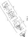
- Fig. 1 shows a reaction vessel (200), sample collection reservoir (300) and liquid transfer device (100) suitable for use in the system illustrated in Fig. 13 .
- Each subassembly can have a D-shaped or otherwise asymmetrical cross section (105, 205, 305) that is compatible with the other two subassemblies, such that the subassemblies may only be mated to each other in one orientation.
- the reaction chamber 200 includes a microtube 220 held within an aperture in the bottom of the reaction vessel body.
- Fig. 1 shows the transfer device 100 and reaction vessel 200 as described above with one pipette tip 120 and one microtube 220.
- the transfer device may, however, have two or more pipette tips, and the reaction vessel may have two or more microtubes.
- Fig. 2 an exploded view of a device (20) according to the invention.
- the device comprises a first part (20a) and a second part (20b).
- the second part (20b) is receivable in the first part (20a).
- Also shown is a sample reservoir (210).
- the first part (20a) is receivable in the sample collection reservoir (210).
- the first part (20a) comprises a main body (21).
- the main body (21) comprises a sample chamber (not shown) and a metering chamber (211).
- the metering chamber (211) and sample chamber are in fluid communication.
- the metering member (22) is in the form of a cup-shaped member with a D-shaped cross-section.
- the metering chamber (211) also has a D-shaped cross-section.
- the metering member (22) will typically contain a dehydrated lytic agent.
- at least one pellet of lytic agent (221) typically potassium hydroxide or sodium hydroxide, held in place by a gauze (222).
- the potassium hydroxide/sodium hydroxide is present to cause rapid lysis of cellular material in the sample fluid, thereby releasing intracellular nucleic acid that is to be detected by isothermal nucleic acid amplification.
- the metering member (22) is movably receivable in the metering chamber (211). In use, the metering member (22) divides the metering chamber into an upper portion and a lower portion. The metering member (22) forms a fluid-tight interference fit with the inner wall of the metering chamber (211). A gas tight membrane (23) closes the end of the metering chamber. In manufacture, the metering member (22) is inserted into the base of the metering chamber (211) and pushed upwards until it sits just beneath the annular seal (not visible) separating the metering chamber from the sample receiving chamber. A gas tight membrane (23) is then heat sealed over the base of the metering chamber (211).
- the second part (20b) comprises a main body (24) comprising an actuator (25) receivable in the sample chamber of the first part (20a).
- the actuator (25) operably engages with the metering member (22).
- the actuator (25) has a distal end (215) and a proximal end (216).
- An aperture (214) is located in the distal end of the actuator (25).
- the aperture (214) is in fluid communication with a separation chamber (not shown) containing an aqueous solution comprising an isothermal nucleic acid amplification buffer and a dispersion of gel-filtration chromatography particles.
- Suitable gel filtration particles are sold under the trade name Sephadex G-25 Superfine by GE Healthcare, other suitable chromatography substrates are known to the skilled person.
- a microfluidic channel (not shown) provides fluid communication between the separation chamber and the exit aperture (217) at the distal end of the return leg (26).
- An insert (27) is inserted in the return leg (26) and closes the separation chamber.
- the outer wall of the actuator (25) comprises a shoulder (213) for engaging the first part.
- a channel (212) is present in the shoulder (213). In use, the channel (213) allows excess liquid to escape the metering chamber before it is sealed.
- Pealable seals (223, 224) are provided on the first part and second part.
- Fig.3 shows the first part of the device (32) before use.
- a pealable seal (31) covers the sample chamber (not shown).
- the pealable seal (31) protects the contents of the first part (32) from contamination, and the dry lytic agent from moisture, before use.
- An intact pealable seal (31) also indicates to the user that the device has not been used before.
- the first part of the device (32) is engaged with a sample reservoir (33).
- Fig. 4 shows the first part of the device (42) with the pealable seal removed.
- the sample chamber (41) is now accessible. Again, the first part of the device (42) is engaged with a sample reservoir (43).
- Fig. 5 shows a second part of the device (60).
- the second part of the device (60) comprises a first actuator leg (63) and a second return leg (62).
- a stopper (61) is fixed in place.
- a pealable seal (64) covers apertures located at the distal ends of the actuator leg and return leg to prevent contamination and/or leakage of the fluid within the actuator.
- the pealable seal (64) is removed before the second part is engaged with the first part.
- the pealable seal (64) prevents contamination and leakage.
- An intact pealable seal (64) indicates to the user that the device has not been used before.
- a microfluidic pathway (not visible) runs from the top of the actuator leg (63) and down the inside of the return leg (62), through which, in use, the processed liquid flows.
- the second part of the device (60) is made in two pieces by injection moulding: an outer wall (65) and an insert (66).
- the insert fills the majority of the return leg (62) and includes the circular part (66) visible on the top surface of the second part (60).
- the insert (27) compresses the top frit (218) down onto the matrix (219) and bottom frit (220) and includes an opening and groove (not shown) that permits processed fluid to move across to the return leg (26).
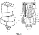
- Fig. 6a shows the device of the invention with the second part (71) inserted in the first part (72). Again the first part of the device (72) is engaged with a sample collection reservoir (73).
- Fig. 6b shows a section through the first (72) and second (71) parts of the device and the sample reservoir (73) shown in Fig. 7a .
- FIG. 6b The cross-section in Fig. 6b reveals the separation chamber (76) containing size exclusion chromatography matrix (75).
- the chamber (76) that contains the matrix is fitted with frits top (77) and bottom (78) to keep the matrix (75) in place.
- the user is instructed to introduce the second part (71) into the first part (72).
- the device is shaped such that it is apparent the actuator leg (79) is the one to be introduced into the chamber (711) into which raw sample is added.
- the narrower portion of the actuator leg initially protrudes through the annular seal (713) and into the metering chamber (714).
- the diameter of the actuator leg is initially smaller than that of the annular seal (713), thus liquid can escape around the edges of the actuator leg (79) into the sample chamber (711) above as the actuator (79) displaces liquid from the upper portion of the metering chamber (712).
- Figs. 6a and 6b the second part (71) has been pushed, by hand, into the first part (72) such that that the shoulder (715) is engaged with an annular seal (713) positioned between the sample chamber (711) and the metering chamber (714).
- the groove (not shown) in the shoulder (715) provides fluid communication between the metering chamber (714) and the sample chamber (711).
- the distal end (718) of the actuator has just engaged the metering member (717).
- the volume of the upper portion of the metering chamber surrounding the actuator defines the volume of raw sample that will pass through the size-exclusion chromatography gel (75).
- the size-exclusion chromatography gel (75) is suspended in a solution comprising a buffer suitable for an isothermal nucleic acid amplification, typically magnesium acetate.
- a buffer suitable for an isothermal nucleic acid amplification typically magnesium acetate.
- concentration of the buffer in the separation chamber (76) will be such that it is present in the correct concentration in the processed sample.
- the metering member (717) is above the upper end of the pressure release channel (719). This means that the pressure release channel (719) is not providing fluid communication between the upper (712) and lower (720) portions of the metering chamber (714). Thus, as the actuator descends further, it advances the metering member (717) and raises the pressure of the air in the lower chamber (720).
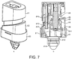
- Figs. 7a and 7b show the device with the second part (81) having been pushed further into the first part (82).
- the actuator shoulder (84) has descended below the annular seal (85) which is now engaged with the outer wall of the actuator (86), thereby sealing the metering chamber (87) from the sample chamber (88).
- the actuator (86) has pushed the metering member (89) to a lower position such that the upper end of the pressure release channel (810) is now exposed above the metering member (89).
- the pressure release channel (810) provides fluid communication between the lower portion (811) of the metering chamber (87) and upper portion (812) of the metering chamber (87) and because the pressure is higher in the lower portion (811) of the chamber that the upper portion (812) of the chamber, air travels along the pressure release channel (810) from the lower portion (811) of the chamber to the upper portion (812) of the chamber forming a high pressure region above the cup-shaped metering member (89) containing the liquid sample as a result of a contraction in the internal volume of the upper portion (812) caused by the presence of the actuator (86) therein. In turn, liquid sample is forced through the orifice (814) in the distal end of the actuator (86) and into the size-exclusion chromatography/separation chamber (815) for treatment.
- a portion of raw sample remains sealed in the sample chamber (88). This can be disposed of with the device.
- the actuator (86) moves the metering member (89) further down within the metering chamber (87), forcing air from the lower portion (811) to the upper portion (812) along the pressure release channel (810) and, thereby, advancing the sample through the size exclusion chromatography gel in the separation chamber (815), along the microfluidic channel (not shown) in the horizontal upper portion of the second part (81) of the device, and along a channel in the return leg (817) of the second part (81), before exiting the second part (81) and dripping into the sample collection reservoir (818).
- the size-exclusion chromatography gel removes isothermal nucleic acid amplification inhibiting agents and/or fluorescent agents from the sample.
- the treated sample which is collected in the sample collection reservoir (818) is sufficiently free from said inhibiting/fluorescent agents that an isothermal nucleic acid amplification can be successfully performed on nucleic acid present in the sample and then detected.
- the size exclusion chromatography gel is suspended in a solution comprising a buffer for performing an isothermal nucleic acid amplification.
- the treated sample collected in the sample collection reservoir (818) is at the correct pH for performing an isothermal nucleic acid amplification. Typically, the pH is from about 6 to about 9. This avoids the need for any further sample preparation steps.
- Figures 8a and 8b show the second part fully inserted (91) into the first part (92).
- An audible prompt typically a click
- the user will typically perform a single push with a finger or thumb until the click is heard.
- the member responsible for the audible click will typically be a latch, which also locks the second part (91) in the first part (92). This also means that unprocessed raw sample is safely contained for disposal.
- a fluid tight seal is created between the top of the second part (91) and the sample chamber (94) to thereby contain excess raw sample fluid (93) and prevent spillage of raw sample when the device is disposed of.
- the sample collection reservoir (910) will contain a treated sample ready for use in an isothermal nucleic acid amplification.
- the treated sample is buffered at the require pH and sufficiently free from nucleic acid amplification inhibiting agents and fluorescent agents for amplification to be performed and detected.
- a liquid transfer device (not shown) is used to pipette a portion of the treated sample from the sample collection vessel (910) to a testing device for performance of an isothermal nucleic acid amplification assay.
- Figs. 9 to 12 show a device (10) according to the invention in-situ in a sample processing device (101) for performing an isothermal nucleic acid amplification.
- a first part (102) of the device according to the invention is located in a sample collection vessel (103), which is, in turn, received in the sample processing device (101).
- Suitable sample processing devices are available from Alere Inc. under the brand name Alere i.
- a reaction vessel (103) is in-situ in the sample processing device.
- the sample processing device may be used with reaction vessels configured to perform NEAR and/or RPA isothermal nucleic acid amplifications.
- the reaction chambers may contain reagents necessary for performing NEAR and/or RPA on samples introduced into said chambers.
- Suitable reaction vessels (105) are available from Alere Inc.
- Fig. 9 the protective pealable film covering sample chamber (104) has been removed.
- the raw sample is introduced into the sample chamber using a pastette, typically 1.5 ml of raw sample will be introduced.
- Fig. 10 shows a system of the invention (11) with the second part (113) of the device partially inserted into the first part (112) of the device (111).
- Fig. 11 shows a system of the invention (12) with the second part (123) of the device (121) fully depressed into the first part (122) of the device (121).
- Fig. 12 shows a liquid transfer device (100), reaction vessel (200) and sample collection reservoir (300), along with a sample processing device (400).
- the screen (440) provides step-by-step instructions to the user and displays the results of the isothermal nucleic acid amplification test.
- the invention contemplates kits comprising a reaction vessel (200), liquid transfer device (100), sample collection chamber (300) and sample preparation device, and systems including the kit and a sample processing device (400).
- FIG. 12 shows the system with an exemplary detection device (400).
- the detection device (400) includes a first station (410) adapted to securely hold the sample collection vessel (300) and a second station (420) adapted to securely hold the reaction chamber (200).
- the transfer device (100) is moved between the sample collection vessel (300) at the first station (410) and the reaction chamber (200) at the second station (420).
- the detection device includes a lid (430) that can be closed when the detection device (400) is in operation or for storage.
- a touchscreen user interface (440) is present for inputting data and displaying information regarding the assay.
- the second station (420) can include a bar code reader or similar device to automatically detect a bar code or similar code present on the reaction chamber (200).
- the first (410) and second (420) stations can be adapted to heat or cool the contents of the sample collection vessel (300) and reaction chamber (200).
- the second station (420) can also be adapted to provide optical, fluorescence, or other monitoring and/or agitation of the microtube (220).
- Fig. 13a to Fig.13e provide a schematic representation of the device during use.
- Fig. 13 a shows the device before use with the second part (142) separated from the first part (141).
- the cup-shaped metering member (143) is at the top of the metering chamber (144) abutted against the annular seal (145) separating the sample chamber (146) from the metering chamber (144).
- raw liquid sample (147) has been introduced into the sample chamber (146) and the cup-shaped metering member (143) in the metering chamber (144).
- the level of the liquid is above annular seal (145).
- movable actuator (148) has been lowered through the sample chamber (146) and into the metering chamber (144), such that a distal end thereof has engaged the metering member (143) and the shoulder (1410) of the moveable actuator (148) is just about to engage the annular seal (145).
- the volume of liquid in the cup-shaped metering member (143) when the annular seal (145) engages the outer wall (1411) of actuator (148) distal to the shoulder (1410) is the predetermined volume of liquid metered for treatment (1412) as in Fig 13d .
- the movable actuator (148) has moved the metering member (143) along the metering chamber (144), reducing the volume of the lower portion (1413) of the metering chamber (144) and increasing the volume of the upper portion (1414).
- the lower and upper portions of the metering chamber (144) are in fluid communication by means of a pressure release channel (1415) in the wall of the metering chamber.
- a pressure release channel (1415) in the wall of the metering chamber.
- the moveable actuator (148) advances into the metering chamber (144) the internal volume of the metering chamber (144) is reduced, thereby increasing the pressure of the air contained therein.
- This increase in air pressure within the metering chamber (144) in turn forces the metered liquid sample (1412) out of the metering chamber (144) through an exit channel (not shown) located in the movable actuator (148).
Description
- The present invention relates to the preparation of samples for isothermal nucleic acid amplification. In particular, to manually operated chromatography devices for preparing samples for isothermal nucleic acid amplification, kits for performing isothermal nucleic acid amplification, and methods for performing isothermal nucleic acid amplification.
- Many diagnostic tests involving biological reactions have to be performed in laboratories by skilled technicians and/or complex equipment. Such laboratories may be the subject of government regulation. The costs of compliance with such regulations can increase the costs of diagnostic tests to patients and health care payers and exclude such tests from point-of-care facilities.
-
WO2013/041713 discloses point-of-care system useful in the performance of isothermal nucleic acid amplifications.WO 95/27199 A1 - It has been found, however, that, in certain circumstances, in order to test certain fluids, such as urine, blood, plasma, serum, saliva, cerebrospinal fluid, tear fluid and sweat, or elute from a vaginal, nasal, throat, penile, anal or skin swab, the raw sample may need to undergo a number of preparation steps prior to their testing in known nucleic acid amplification assays.
- There is, therefore, an unmet need for devices, methods and kits that enable the point-of-care preparation of the samples for isothermal nucleic acid amplification and other tests. Such devices need to be simple to use and inexpensive to produce.
- The present invention addresses these and other issues with the prior art.
- Accordingly, in a first aspect, the present invention provides a chromatography device as defined in claim 1.
- The device is manually actuated. The device comprises a chamber for receiving a liquid sample, a pump with a metering valve, and a chromatography element. Preferably, the device is a size exclusion chromatography device and the chromatography element is a size exclusion chromatography element: gel-filtration chromatograph elements are particularly preferred. In use, the pump moves a predetermined volume of liquid from the sample chamber to the chromatography element. Typically, the pump moves a predetermined volume of liquid from the sample chamber through the chromatography element. Preferably, the pump moves a predetermined volume of liquid from the sample chamber through the chromatography element to a sample collection vessel. Preferably the device is single use.
- Alternative stationary phase chromatography elements may also be employed in the device of the invention. Suitable alternative stationary phase chromatography elements include, but are not limited to, ion exchange chromatography elements, including cation and anion exchange chromatography elements, reversed-phase chromatography elements, and affinity chromatography elements. Accordingly, the device of the invention can be used for ion exchange chromatography, reversed-phase chromatography and affinity chromatography.
- Preferably, the device is actuatable by a single movement, typically a single push or rotation.
- Typically, in use, the pump and/or pumping is pneumatic. This is advantageous because it means the separation performance of the device is substantially independent of the force and speed with which the device is actuated. Essentially, the rate at which the liquid sample passes through the chromatography element is substantially independent of the force applied by the user.
- Preferably, the processing of the liquid sample is completed within a predetermined period of time of at least about 30 seconds, at least about 1 minute, at least about 2 minutes, at least about 3 minutes, at least about 4 minutes, at least about 5 minutes, at least about 6 minutes, at least about 7 minutes, at least about 8 minutes, at least about 9 minutes, at least about 10 minutes. Preferably, less than about 10 minutes, preferably less that about 8 minutes, preferably less than about 7 minutes, preferably less than about 6 minutes, preferably less than about 5 minutes, preferably less than about 4 minutes. Preferably processing of the liquid sample is completed within a predetermined period of time from about 1 minute to about 5 minutes, from about 1 minute to about 3 minutes is particularly preferred.
- In embodiments, the predetermined volume of fluid is from about 0.1 to about 100 ml, preferably from about 0.25 ml to about 10 ml, more preferably from about 0.5 ml to about 1 ml. Preferably the predetermined volume of fluid is at least about 100µL, at least about 200µL, at least about 300µL, at least about 400µL, at least about 500µL, at least about 600µL, at least about 700µL, at least about 800µL, at least about 900µL, at least about 1mL, at least about 2mL, at least about 3mL, at least about 4mL, at least about 5mL.
- In all aspects of the invention, the sample to be tested, i.e. the liquid or raw sample, will typically be a biological fluid, such as urine, blood, plasma, serum, saliva, cerebrospinal fluid, tear fluid or elute from a vaginal, nasal, throat, penile, anal or skin swab.
- It has been found that raw samples of certain fluids, such as those indicated above, may contain agents which in some circumstances negatively influence the performance of assays and, in particular, contain agents which negatively interfere with the performance of isothermal nucleic acid amplification assays. The negative interference may take the form of inhibiting nucleic acid amplification itself and/or agents which fluoresce such that amplification cannot be reliably detected. It was found that these assay interference agents tend to have a lower molecular weight than target nucleic acids and can thus be removed by a size-exclusion chromatography. The present invention enables the size exclusion chromatography to be performed in a simple, one-step process, in a point-of-care environment. Thereby, enabling testing to be performed more quickly and any treatment required implemented more rapidly, providing benefits for patients and healthcare professionals alike. It is recognised, that not all assay/nucleic acid interference agents are removed; however, sufficient quantity will be removed to enable nucleic acid amplification to be performed and measured. Typically, substantially all of the nucleic acid amplification interference agents are removed. Typically, the nucleic acid amplification interference agents will be salts and low molecular weight molecules, such as proteins or lipids, present in the liquid sample, typically with a molecular weight of less than about 5000kDa. Typically, the size-exclusion chromatography element removes molecules with a molecular weight of less than about 5000kDa. The skilled person will appreciate that the molecular weight cut-off can be increased or decreased by selecting different chromatography resins.
- Isothermal nucleic acid amplification assays with which the invention can be used include recombinase polymerase amplification (RPA), nicking and extension amplification reaction (NEAR), strand displacement amplification, and loop mediated isothermal amplification.
- Nicking and extension amplification reactions are discussed in detail in
WO2009/012246 . - Recombinase Polymerase Amplification reactions are discussed in detail in
WO2003/072805 ,WO2005/118853 ,WO2010/141940 ,WO2008/035205 ,WO2007/096702 ,WO2011/038197 andWO2012/138989 . - As well as isothermal nucleic acid amplification assays, the invention can also be used to prepare liquid samples for an immunoassays, a mass-spectrophotometric assays, and polymerase chain reaction assays.
- In embodiments of the invention, the device comprises a first part and a second part receivable in the first part. The first part and second part operably engage to move a predetermined volume of fluid from the sample chamber to the chromatography element. The pump is actuated by the second part of the device operably engaging the first part of the device. Likewise, the metering valve is actuated by the second part of the device operably engaging the first part of the device.
- The metering valve comprises a metering chamber with an upper portion and a lower portion separated by a movable metering member. The upper and lower portions of the metering chamber are therefore variable in volume. Typically, the metering member and metering chamber will have matching asymmetric cross-sections. Typically, the inner wall of the metering chamber will have a D-shaped cross-section. Similarly, the outer wall of the metering member will typically have a D-shaped cross-section, receivable in the metering chamber. Typically, the metering member will form an interference fit, preferably a fluid-tight interference fit, with the inner wall of the metering chamber. Preferably, the metering member is a cup.
- The upper portion and lower portion of the metering chamber are selectively in fluid communication. That is to say, they may be in configurations where they are in fluid communication and other configurations where they are not. The metering valve comprises a fluid by-pass or pressure release channel for providing fluid communication between the upper and lower portions of the metering chamber. Movement of the metering member relative to the fluid by-pass channel allows selective fluid communication between the upper and lower portions of the metering chamber. If the metering member is above the fluid by-pass channel there is no fluid communication between the two portions of the metering chamber. The metering member can, however, be lowered to expose the fluid by-pass channel. The fluid by-pass channel is a pressure release channel. The fluid by-pass channel releases air under pressure from the lower portion of the metering to the upper portion of the chamber.
- In embodiments, the device comprises a lytic agent for treating the sample before the sample reaches the chromatography element. Exposing the sample to a lytic agent causes rapid lysis of any cells present in the liquid sample, releasing intracellular nucleic acid for testing. Typically, a lytic agent is located in the metering chamber. The lytic agent will preferably be selected from the group consisting of surfactant or a base. Preferred bases include potassium hydroxide and sodium hydroxide. At least one pellet of potassium hydroxide or sodium hydroxide, typically held in place by a mesh, is particularly preferred. Preferred surfactants may be selected from the group consisting of sodium dodecyl sulphate, Triton®, Tween®, Brij®, cetyl trimethylammonium bromide and combinations thereof. Typically, the lytic agent will be dry.
- It is advantageous to lyse the contents of the liquid sample ahead of the chromatography so that isothermal nucleic acid amplification inhibiting agents produced during cell lysis are also removed.
- Typically, the chromatography element comprises a separation chamber containing a chromatography substrate. Preferably, the size exclusion chromatography element comprises a separation chamber containing a size exclusion chromatography gel suspension. Preferably, the chromatography element, preferably size exclusion chromatography element, comprises a solution comprising a buffer for an assay, preferably for an isothermal nucleic acid amplification, preferably magnesium acetate. Preferably, the size exclusion chromatography element comprises a solution comprising a buffer for an isothermal nucleic acid amplification with gel filtration chromatography particles suspended therein.
- The concentration of the buffering agent in the size exclusion chromatography element is selected so that the concentration of buffer in the processed sample is at the desired level. Typical concentrations for the buffer in the size exclusion chromatography element are from about 10 mM to about 200 mM. Preferably the pH of processed sample is from about pH 6 to about pH 9. These preferred pHs and concentrations apply to all aspects of the invention. The specific concentration and pH selected will depend on the application, e.g. RPA or NEAR.
- Such arrangements are advantageous because then the processed sample collected in the collection vessel is immediately ready for testing, reducing the number of steps in the process.
- Preferred gel filtration particles useful in all aspects of the invention have a particle size range of from about 10 µm to about 100 µm, more preferably from about 15 µm to about 88 µm and, preferably, a fractionation range of 1000 to 5000 Da for peptides and globular proteins. Preferably the particles comprise dextran cross-linked with epichlorohydrin. Alternative, chromatography gels can be chosen by the skilled person depending on the characteristics of the agents that need to be removed from the sample.
- An aspect beyond the scope of the present invention provides a device for preparing a sample for an assay, preferably for isothermal nucleic acid amplification, comprising a first part and a separate second part receivable in the first part, wherein the first part comprises a vessel for receiving the sample and the second part comprises a separation element for removing assay interfering agents, preferably nucleic acid amplification inhibiting agents and/or fluorescent agents, from the sample. When the second part is received in the first part, the first and second part operably engage to move sample from the sample chamber to the separation element. Preferably the device is single use. Preferably, the device is manually actuated, preferably the device is actuatable by a single user applied push or rotation.
- Typically, the first part comprises a metering valve for metering a predetermined volume of sample from the sample chamber and may be actuated by the second part of the device engaging the first part of the device.
- In use, the device will usually pump a predetermined volume of fluid from the sample chamber through the separation element. Preferably, the pump moves a predetermined volume of fluid from the sample chamber through the separation element to a sample collection vessel. Preferably, the predetermined volume of fluid is from about 0.1 to about 100 ml, preferably from about 0.25 to about 10 ml, more preferably from about 0.5 to about 1 ml. Preferably the pump is pneumatic.
- The metering valve will typically comprise a metering chamber with an upper portion and a lower portion separated by a movable metering member.
- Typically, the metering valve comprises a metering chamber with an upper portion and a lower portion separated by a movable metering member. The upper and lower portions of the metering chamber are therefore variable in size. Typically, the inner wall of the metering chamber will have D-shaped cross-section. Similarly, the outer wall of the metering member will typically have a D-shaped cross-section, receivable in the metering chamber. Typically, the metering member will have an interference fit, preferably a fluid-tight interference fit, with the inner wall of the metering chamber. Preferably, the metering member is a cup.
- In embodiments, the upper portion and lower portion of the metering chamber are selectively in fluid communication. That is to say, they may be in configurations where they are in fluid communication and other configurations where they are not. The metering valve may, for instance, comprise a fluid by-pass channel for providing fluid communication between the upper and lower portions of the metering chamber. Movement of the metering member relative to the fluid by-pass channel may allow selective fluid communication between the upper and lower portions of the metering chamber. Typically, the fluid by-pass channel is a pressure release channel.
- In further embodiments, the device comprises a lytic agent for treating the sample before the sample is moved to the separation element. Typically, a lytic agent is located in the metering chamber. The lytic agent will preferably be selected from the group consisting of surfactant or a base. Preferred bases include potassium hydroxide and sodium hydroxide. The use of a material mesh doped with potassium hydroxide or at least one potassium hydroxide or sodium hydroxide pellet, preferably held in place by a mesh, are particularly preferred. Preferred surfactants may be selected from the group consisting of sodium dodecyl sulphate, Triton@, Tween®, Brij@, cetyl trimethylammonium bromide and combinations thereof.
- As discussed above, it is advantageous to perform lysis ahead of the separation because assay interfering agents produced during lysis may also be removed.
- The separation element typically comprises a size exclusion chromatography suspension. Preferably, the separation element comprises a solution comprising a buffer for an isothermal nucleic acid amplification, preferably magnesium acetate, Tris or phosphate buffers.
- In alternative embodiments the separation element may comprise a filter or a suitable stationary phase chromatography element selected from the group of ion exchange chromatography elements, including cation and anion exchange chromatography elements, reversed-phase chromatography elements, and affinity chromatography elements. Accordingly, the device of the invention can be used for ion exchange chromatography, reversed-phase chromatography and affinity chromatography.
- A further aspect outside the scope of the present invention provides a device for preparing a sample for an isothermal nucleic acid amplification comprising a lytic element and a separation element for removing nucleic acid amplification inhibiting agents and/or fluorescent agents from the lysate.
- Typically, the lytic element comprises a lytic agent. The lytic agent will preferably be selected from the group consisting of surfactant or a base. Preferred bases include potassium hydroxide and sodium hydroxide. A material mesh doped with potassium hydroxide is particularly preferred; more preferred is the use of at least one pellet of potassium hydroxide or sodium hydroxide, typically held in place by a mesh. Preferred surfactants may be selected from the group consisting of sodium dodecyl sulphate, Triton®, Tween®, Brij®, cetyl trimethylammonium bromide and combinations thereof.
- Also disclosed herein is a metering valve containing a metering chamber comprising a dry lytic agent.
- The lytic agent will preferably be selected from the group consisting of surfactant or a base. Preferred bases include potassium hydroxide and sodium hydroxide. A material mesh doped with potassium hydroxide is particularly preferred: more preferred is the use of at least one pellet of potassium hydroxide or sodium hydroxide, typically held in place by a mesh. Preferred surfactants may be selected from the group consisting of sodium dodecyl sulphate, Triton®, Tween®, Brij®, cetyl trimethylammonium bromide and combinations thereof.
- In a further aspect of the invention, a kit is provided for performing an isothermal nucleic acid amplification on a sample. The kit will comprise, in combination with the chromatography device of the invention, a liquid transfer device, preferably comprising a housing having a pipette tip and a plunger assembly; a reaction chamber containing reagents for an isothermal nucleic acid amplification reaction; a sample reservoir; and a sample preparation device comprising a separation element capable of removing nucleic acid amplification inhibiting agents and/or fluorescent agents from the sample before performing the isothermal nucleic acid amplification.
- In embodiments of the kit, the reaction vessel contains the reagents for a recombinase polymerase amplification (RPA), such as a recombinase, a single strand binding protein and a polymerase. The recombinase may be selected from T4 UvsX, T6 UvsX, or RecA. The DNA polymerase may be selected from the group consisting of E. coli DNA polymerase I Klenow fragment, B. stearothermophilus polymerase (Bst), B. subtilis Phi-29 polymerase, B. subtilis polymerase I (Bsu). The single strand binding protein is typically gp32.
- The reagents for a recombinase polymerase amplification which typically also include a crowding agent, ATP (adenosine triphosphate) or an ATP analogue, dNTP(s), or T4 bacteriophage UvsY. Preferred crowding agents may be selected from the group comprising (preferably consisting of) polyethylene glycol (PEG), dextran, polyvinylalcohol (PVA), polyvinypyrrolidone (PVP) or Ficoll.
- When present, the PEG is preferably PEG1450, PEG3000, PEG8000 or PEG10000. PEG will preferably have a molecular weight between about 15000 and about 20000.
- When present, the dNTP(s) is/are preferably selected from the group consisting of dATP, dGTP, dCTP, and dTTP.
- When present, the ATP or ATP analogue is typically selected from ATP, ATP-γ-S, ATB-β-S, ddATP or a combination thereof.
- Alternatively, the reaction vessel may contain the reagents for a nicking and extension amplification reaction (NEAR). NEAR reagents typically comprise a nicking enzyme, a forward template nucleic acid, a reverse template nucleic acid, and a polymerase.
- Reagents are typically in dried form or freeze dried form but may be in liquid form.
- The kit may further comprise a patient collection vessel and a pastette for transferring fluid from the patient collection vessel to the sample preparation device.
- Preferably, the sample preparation device contains a lytic agent to which sample is exposed prior to the separation element removing nucleic acid amplification inhibiting agents and/or fluorescent agents from the lysate. The use of at least one pellet of potassium hydroxide or sodium hydroxide, typically held in place by a mesh is particularly preferred.
- Typically, the separation element comprises a separation chamber containing a size exclusion chromatography gel suspension. Preferably, the size exclusion chromatography element comprises a solution comprising a buffer for an isothermal nucleic acid amplification, preferably magnesium acetate. Preferably the size exclusion chromatography element comprises a solution comprising a buffer for an isothermal nucleic acid amplification and a suspension of gel filtration chromatography particles.
- In unclaimed embodiments the separation element may comprise a filter.
- The sample preparation device may be a device according to any of the previous aspects of the invention.
- Specifically, the sample preparation device may be a manually actuated size-exclusion chromatography device. The device comprises a chamber for receiving a liquid sample, a pump with a metering valve, and a size-exclusion chromatography element. In use, the pump moves a predetermined volume of liquid from the sample chamber to the size-exclusion chromatography element. Typically, the pump moves a predetermined volume of fluid from the sample chamber through the size-exclusion chromatography element. Preferably, the pump moves a predetermined volume of fluid from the sample chamber through the size-exclusion chromatography element to a sample collection vessel. Preferably the device is single use. Preferably, the device is actuatable by a single downward push or rotation. Typically, the pump is pneumatic.
- Alternatively, the sample preparation device may be a device for preparing a sample for isothermal nucleic acid amplification comprising a first part and a separate second part receivable in the first part, wherein the first part comprises a vessel for receiving the sample and the second part comprises a separation element for removing nucleic acid amplification inhibiting agents and/or fluorescent agents from the sample, wherein when the second part is received in the first part, the first and second part operably engage to move sample from the sample chamber to the separation element.
- Alternatively, the sample preparation device may comprise a lytic element and a separation element for removing nucleic acid amplification inhibiting agents and/or fluorescent agents from the lysate.
- In embodiments, the housing of the liquid transfer device is configured to sealably engage with the reaction chamber. In some embodiments, the housing of the liquid transfer device can include a seal component configured to sealably engage with the reaction chamber. In some embodiments, the reaction chamber can include a seal component configured to sealably engage with the liquid transfer device. The systems can further include a fluid reservoir, and the reaction chamber can optionally be configured to lockably engage with the fluid reservoir.
- Preferably, the sample preparation device may be removably engaged with the fluid reservoir. Preferably, the sample preparation device is actuated while positioned in the fluid reservoir, preferably by pushing the device against the fluid reservoir. Typically, the prepared sample is collected in the fluid reservoir.
- The liquid transfer device can be configured to lockably engage with the reaction chamber, e.g., without dispensing, prior to dispensing, and/or after dispensing a liquid sample. In some embodiments, the reaction chamber includes one or more components of a biological reaction.
- The liquid transfer device may include a housing having a pipette tip; and a plunger assembly disposed within the housing and the pipette tip, wherein a portion of the plunger assembly is configured to engage a fluid reservoir such that the plunger assembly remains stationary relative to the fluid reservoir and the housing moves relative to the plunger assembly.
- Typically, movement of the housing relative to the plunger assembly results in creation of a vacuum within the pipette tip and, optionally, the plunger assembly can be configured to lock in a position resulting in creation of the vacuum. The housing can be configured to move relative to the plunger assembly by pushing the housing down on the fluid reservoir. The device can further be configured to provide an auditory and/or visual indication that the plunger assembly is in a position resulting in the creation of the vacuum.
- The kit may include the liquid transfer device and one or more of a fluid reservoir and reaction chamber. The reaction chamber can be configured to unlock the plunger assembly when the liquid transfer device and the reaction chamber are interfaced.
- The liquid transfer device may be configured to draw a sample from a fluid reservoir by pushing the device against the reservoir and systems that include the liquid transfer device and one or both of a reaction chamber and fluid reservoir.
- In the systems described above, all four of the liquid transfer device, reaction chamber, sample preparation device and fluid reservoir can have compatible asymmetric cross-sections.
- In a further aspect the invention provides a system for performing isothermal nucleic acid amplification comprising a kit according to the previous aspect of the invention and a detection device.
- The detection device will typically include a first station adapted to securely hold the sample collection chamber and a second station adapted to securely hold the reaction chamber. When in use, the sample preparation device is positioned in the sample collection chamber. Typically, the first part of the device will be placed into the sample collection chamber. Then, a raw sample is placed into the metering chamber of the device. Then, the second part of the device is inserted into the first part of the device. The second part of the device is then pushed into the first part, typically until an audible or visual signal is given, and a prepared sample is collected in the sample collection vessel. The sample preparation device is then removed and disposed of.
- The transfer device is movable between the collection chamber at the first station and the reaction chamber at the second station.
- The detection device includes a lid that can be closed when the detection device is in operation or for storage.
- A touchscreen user interface may be present for inputting data and displaying information regarding the assay. The second station can include a bar code reader or similar device to automatically detect a bar code or similar code present on the amplification chamber. The first and second stations can be adapted to heat or cool the contents of the sample collection chamber and reaction chamber. The second station can also be adapted to provide optical, fluorescence, or other monitoring and/or agitation of the microtube.
- In some embodiments, a liquid transfer device or pipette tip disclosed herein can be configured to collect and dispense a volume between 1 µl and 5 ml (e.g., between any two of 1 µl, 2 µl, 5 µl, 10 µl, 20 µl, 50 µl, 100 µl, 200 µl, 500 µl, 1 ml, 2 ml, and 5 ml.
- In a further aspect, the present invention provides a method for performing an isothermal nucleic acid amplification. The method comprises the steps of providing a raw liquid sample for testing; processing the raw liquid sample to remove nucleic acid amplification inhibiting agents and/or fluorescent agents; performing an isothermal nucleic acid amplification on the processed sample; and monitoring for amplified nucleic acid, wherein the processing step is performed with a chromatography device of the invention.
- An aspect beyond the scope of the present invention provides a composition for use in gel-filtration chromatography comprising an aqueous solution comprising an isothermal nucleic acid amplification buffer, and a dispersion of gel-filtration chromatography particles. Typically, the buffer is selected from the group consisting of magnesium acetate or Tris acetate; preferably magnesium acetate.
- Preferred gel filtration particles have a particle size range of from about 10 µm to about 100 µm, more preferably from about 15 µm to about 88 µm and, preferably, a fractionation range of about 1000 to about 5000 Da for peptides and globular proteins. Preferably the particles comprise dextran cross-linked with epichlorohydrin. Alternative, size exclusion chromatography gels can be chosen by the skilled person.
- Herein is also disclosed the use of such compositions in the preparation of a sample for isothermal nucleic acid amplification.
- The device of the present invention includes a metering valve for a pump. The metering valve will comprise a metering chamber having an upper portion and a lower portion separated by a movable metering member; and a pressure release channel.
- The metering member and pressure release channel are arranged such that the metering member is movable from an initial position in which the metering member separates the upper portion from the lower portion to a subsequent position in which the pressure release channel provides fluid communication between the lower portion of the metering chamber and the upper portion of the metering chamber.
- Thus, as the metering member descends, thereby reducing the volume of lower portion of the metering chamber, the pressure increases in the lower portion of the metering chamber. After the metering member has advanced a predetermined distance, the pressure release channel is able to provide fluid communication between lower and upper portions of the metering chamber. Once in fluid communication, air from the lower portion of the metering chamber will move along the pressure release channel, and displace fluid in the upper portion of the metering chamber.
- Typically, a fluid exit channel is provided. Preferably, the fluid is displaced along the exit channel and, thereby, exits the metering valve. In a preferred embodiment, the fluid exit channel is located within a movable actuator for the metering valve. In such embodiments, the moveable actuator operably engages the metering member, such that movement of the actuator meters a predetermined volume of sample and pumps the predetermined volume out of the exit channel.
- Typically, the metering member will have an interference fit, preferably a fluid-tight interference fit, with the inner wall of the metering chamber. The inner wall of the metering chamber may have an asymmetric cross-section, preferably D-shaped cross-section. Similarly, the outer wall of the metering member may have asymmetric cross-section, typically D-shaped cross-section, matching the cross-section of the metering chamber. Preferably, the metering member is a cup. Typically, the moveable actuator operably engages the inside floor of the cup.
- Typically, the metering chamber will have a single opening for receiving a liquid sample to be metered and the movable actuator. Typically, the perimeter of the opening of the metering chamber will form an interference fit, preferably a fluid-tight interference fit with an outer wall of the movable actuator when it is received within the opening.
- Also disclosed herein is a method of manufacturing a single use metering valve. The method comprises the steps of providing a metering chamber with a first opening and a second opening and a pressure release channel extending partially along an internal wall of the chamber, typically in an axial direction; providing a metering member receivable in the metering chamber so as to separate the metering chamber into a first portion and second portion; locating the metering member in the metering chamber such that the pressure release channel does not provide fluid communication between the first portion and second portion, and sealing an opening of the metering chamber with a seal. Typically, the metering member is movable within the metering chamber. Preferably, the metering member is slid into position via the opening to be sealed and, preferably, the other opening is not sealed.
- In embodiments of the method, the metering member is prevented from moving through the first opening, preferably by an abutment, preferably an annular abutment, more preferably by an annular abutment at the first opening.
- Typically, the metering member is entered into the metering chamber through the second opening and is advanced along the metering chamber until the metering member engages an abutment, typically annular abutment.
- Preferably, the metering member forms an interference fit with the metering chamber, preferably a fluid-tight interference fit. Preferably, the metering member is a cup.
- The device of the present invention further includes a manually actuated pump comprising a first part and a separate second part operably receivable in the first part. The first part and second part engage to form a metering valve, the first part comprises a metering chamber for receiving a liquid sample, a moveable metering member and a pressure release channel, and the second part comprises an actuator arranged to operably engage the metering member when the second part is received in the first part. In use, the second part is advanced into the first part and a predetermined volume of fluid exits the pump through an exit channel, said predetermined volume of fluid will typically comprise a predetermined volume of the liquid sample and a predetermined volume of air. Typically, the exit channel is provided in the second part. In a preferred embodiment, the fluid exit channel is located within the actuator. The pump is, typically, single use.
- Typically, the metering chamber will have a single opening for receiving a liquid sample to be metered and the actuator. Typically, the perimeter of the opening of the metering chamber will form an interference fit, preferably a fluid-tight interference fit with an outer wall of the actuator when it is received within the opening.
- Typically, the metering member will have an interference fit, preferably a fluid-tight interference fit, with the inner wall of the metering chamber. The metering member thereby separates the metering chamber into an upper and lower portion. The inner wall of the metering chamber may have an asymmetric cross-section, preferably D-shaped cross-section. Similarly, the outer wall of the metering member may have asymmetric cross-section, typically D-shaped cross-section, matching the cross-section of the metering chamber. Preferably, the metering member is a cup. Typically, the moveable actuator operably engages the inside floor of the cup.
- In use, the volume of fluid, typically air, displaced by the actuator as it is advanced into the metering chamber results in an increase in pressure within an upper portion of the metering chamber and thereby moves the predetermined volume of fluid through the exit channel. Selecting the correct volume displacement is within the competence of the skilled person.
- The pressure release channel provides selective fluid communication between the upper and lower portions of the metering chamber. When the metering member is in its initial position the upper and lower portions of the metering chamber are separate, i.e. not in fluid communication. As the metering member is moved along the metering chamber by the actuator the pressure release channel is exposed and fluid communication between the upper and lower portions of the metering chamber is achieved. In a preferred embodiment, the pressure release channel is located in a wall of the metering chamber. The pressure release channel may be in the form of an open groove or an enclosed conduit. Typically, the pressure release channel will extend from at or near to the base of the metering chamber to a location below the top of the metering member in its initial position.
- Preferably, the metering chamber comprises a lytic agent. Suitable lytic agents have been discussed earlier in the present disclosure.
- An aspect beyond the scope of the present invention provides a pump, preferably a manually actuated pump, for metering a predetermined volume of liquid comprising: a vessel comprising a sample chamber and a metering chamber; an actuator containing a fluid exit channel with an opening in a distal portion of the actuator, wherein the actuator is movable from a first position, in which the actuator's distal end is located in the sample chamber, to a second position, in which the opening of the fluid exit channel is located in the metering chamber, and wherein when the actuator is in first position, the sample chamber is in fluid communication with metering chamber, and when the actuator is in the second position, the sample chamber is separated from the metering chamber; wherein the metering chamber is divided into an upper portion and a lower portion by a movable metering member and wherein the metering chamber further comprises a pressure release channel; and wherein the metering member, pressure release channel and actuator are arranged such that as the actuator is moved from its first position to its second position, the metering member moves from an initial position in which the metering member separates the upper portion from the lower portion to a subsequent position in which the pressure release channel provides fluid communication between the lower portion of the metering chamber and upper portion of the metering chamber.
- Typically, the metering member will have an interference fit, preferably a fluid-tight interference fit, with the inner wall of the metering chamber. The metering member thereby separates the metering chamber into an upper portion and lower portion. The inner wall of the metering chamber may have an asymmetric cross-section, preferably D-shaped cross-section. Similarly, the outer wall of the metering member may have asymmetric cross-section, typically D-shaped cross-section, matching the cross-section of the metering chamber. Preferably, the metering member is a cup. Typically, the moveable actuator operably engages the inside floor of the cup.
- In use, the volume of fluid, typically air, displaced by the actuator as it is advanced into the metering chamber results in an increase in pressure within an upper portion of the metering chamber and thereby moves the predetermined volume of fluid through the fluid exit channel. The volume of the upper portion of the metering chamber displaced by the actuator should preferably be greater than the volume of the liquid sample to be moved such that when the metering member is fully displaced by the actuator all of the liquid sample in the upper portion of the metering chamber is forced out of the metering chamber. An excess volume ensures that a volume of air also passes through the second part of the device to prevent dripping and ensure dose uniformity. Selecting the correct volume of the metering chamber to be displaced by the actuator is within the competence of the skilled person.
- In a preferred embodiment, the pressure release channel is located in a wall of the metering chamber. The pressure release channel may be in the form of an open groove or a closed conduit. Typically, the pressure release channel will extend from at or near to the base of the metering chamber to a location below the top of the metering member in its initial position.
- Preferably, the metering chamber and/or the sample chamber comprises a lytic agent. Suitable lytic agents have been disclosed earlier in this disclosure.
- The pump is, typically, single use. For the purposes of the invention, single use means that in normal use the pump cannot be reset and reused.
- Pumps and metering valves according these aspects are specifically contemplated for use in the devices according to the earlier described aspects of the invention.
- For the purpose of the invention, manually actuated has its normal meaning. That is to say, that the devices, pumps and metering valves are actuatable by hand. All of the devices, pumps and metering valves of the invention can be manually actuated, although it is contemplated that certain aspects and embodiments of the invention may also be actuated by alternative means.
- The details of one or more embodiments of the invention are set forth in the accompanying drawings and the description below. Other features, objects, and advantages of the invention will be apparent from the description and drawings, and from the claims.
-
-
Fig. 1 shows a prior art system. -
Fig. 2 shows an exploded view of an exemplary device. -
Fig. 3 shows an exemplary first part of the device before use. -
Fig. 4 shows an exemplary first part of the device with the sample chamber cover removed. -
Fig. 5 shows an exemplary second part of the device. -
Fig. 6 shows the second part engaging the first part and metering a volume of the raw sample. -
Fig. 7 shows the second part having displaced the metering member. -
Fig.8 shows the second part fully depressed. -
Fig.9 to Fig. 11 shows an exemplary device in-situ in a device for performing and monitoring isothermal nucleic acid amplification. -
Fig. 12 shows prepared sample being transported to a reaction chamber. -
Fig. 13a to Fig. 13e provide a schematic representation of the metering chamber during use. - The present invention relates to the preparation of samples for use in assays and in particular in the preparation of samples for use in isothermal nucleic acid amplification. In particular, to manually operated chromatography devices for preparing samples for isothermal nucleic acid amplification, kits for performing isothermal nucleic acid amplification, and methods for performing isothermal nucleic acid amplification.
-
Fig. 1 shows a reaction vessel (200), sample collection reservoir (300) and liquid transfer device (100) suitable for use in the system illustrated inFig. 13 . Each subassembly can have a D-shaped or otherwise asymmetrical cross section (105, 205, 305) that is compatible with the other two subassemblies, such that the subassemblies may only be mated to each other in one orientation. - The
reaction chamber 200 includes amicrotube 220 held within an aperture in the bottom of the reaction vessel body. -
Fig. 1 shows thetransfer device 100 andreaction vessel 200 as described above with onepipette tip 120 and onemicrotube 220. The transfer device may, however, have two or more pipette tips, and the reaction vessel may have two or more microtubes. - Such assemblies are discussed in detail in
WO2013/041713 which is incorporated herein by reference. -
Fig. 2 an exploded view of a device (20) according to the invention. The device comprises a first part (20a) and a second part (20b). The second part (20b) is receivable in the first part (20a). Also shown is a sample reservoir (210). The first part (20a) is receivable in the sample collection reservoir (210). - The first part (20a) comprises a main body (21). The main body (21) comprises a sample chamber (not shown) and a metering chamber (211). The metering chamber (211) and sample chamber are in fluid communication. The metering member (22) is in the form of a cup-shaped member with a D-shaped cross-section. The metering chamber (211) also has a D-shaped cross-section. The metering member (22) will typically contain a dehydrated lytic agent. Typically at least one pellet of lytic agent (221), typically potassium hydroxide or sodium hydroxide, held in place by a gauze (222). The potassium hydroxide/sodium hydroxide is present to cause rapid lysis of cellular material in the sample fluid, thereby releasing intracellular nucleic acid that is to be detected by isothermal nucleic acid amplification.
- The metering member (22) is movably receivable in the metering chamber (211). In use, the metering member (22) divides the metering chamber into an upper portion and a lower portion. The metering member (22) forms a fluid-tight interference fit with the inner wall of the metering chamber (211). A gas tight membrane (23) closes the end of the metering chamber. In manufacture, the metering member (22) is inserted into the base of the metering chamber (211) and pushed upwards until it sits just beneath the annular seal (not visible) separating the metering chamber from the sample receiving chamber. A gas tight membrane (23) is then heat sealed over the base of the metering chamber (211).
- The second part (20b) comprises a main body (24) comprising an actuator (25) receivable in the sample chamber of the first part (20a). In use, the actuator (25) operably engages with the metering member (22). The actuator (25) has a distal end (215) and a proximal end (216). An aperture (214) is located in the distal end of the actuator (25). The aperture (214) is in fluid communication with a separation chamber (not shown) containing an aqueous solution comprising an isothermal nucleic acid amplification buffer and a dispersion of gel-filtration chromatography particles. Suitable gel filtration particles are sold under the trade name Sephadex G-25 Superfine by GE Healthcare, other suitable chromatography substrates are known to the skilled person. A microfluidic channel (not shown) provides fluid communication between the separation chamber and the exit aperture (217) at the distal end of the return leg (26). An insert (27) is inserted in the return leg (26) and closes the separation chamber. The outer wall of the actuator (25) comprises a shoulder (213) for engaging the first part. A channel (212) is present in the shoulder (213). In use, the channel (213) allows excess liquid to escape the metering chamber before it is sealed.
- Pealable seals (223, 224) are provided on the first part and second part.
-
Fig.3 shows the first part of the device (32) before use. A pealable seal (31) covers the sample chamber (not shown). The pealable seal (31) protects the contents of the first part (32) from contamination, and the dry lytic agent from moisture, before use. An intact pealable seal (31) also indicates to the user that the device has not been used before. The first part of the device (32) is engaged with a sample reservoir (33). -
Fig. 4 shows the first part of the device (42) with the pealable seal removed. The sample chamber (41) is now accessible. Again, the first part of the device (42) is engaged with a sample reservoir (43). -
Fig. 5 shows a second part of the device (60). The second part of the device (60) comprises a first actuator leg (63) and a second return leg (62). A stopper (61) is fixed in place. A pealable seal (64) covers apertures located at the distal ends of the actuator leg and return leg to prevent contamination and/or leakage of the fluid within the actuator. - In use, the pealable seal (64) is removed before the second part is engaged with the first part. The pealable seal (64) prevents contamination and leakage. An intact pealable seal (64) indicates to the user that the device has not been used before.
- A microfluidic pathway (not visible) runs from the top of the actuator leg (63) and down the inside of the return leg (62), through which, in use, the processed liquid flows.
- The second part of the device (60) is made in two pieces by injection moulding: an outer wall (65) and an insert (66). The insert fills the majority of the return leg (62) and includes the circular part (66) visible on the top surface of the second part (60). There is a groove in the return leg portion of the insert (not shown) that forms a closed channel when inserted in the return leg (62). As better shown in
Fig. 2 , in the actuator leg (25), the insert (27) compresses the top frit (218) down onto the matrix (219) and bottom frit (220) and includes an opening and groove (not shown) that permits processed fluid to move across to the return leg (26). -
Fig. 6a shows the device of the invention with the second part (71) inserted in the first part (72). Again the first part of the device (72) is engaged with a sample collection reservoir (73). -
Fig. 6b shows a section through the first (72) and second (71) parts of the device and the sample reservoir (73) shown inFig. 7a . - The cross-section in
Fig. 6b reveals the separation chamber (76) containing size exclusion chromatography matrix (75). The chamber (76) that contains the matrix, is fitted with frits top (77) and bottom (78) to keep the matrix (75) in place. There are also cut out features (cross shapes) in the moulded plastic that permit fluid to spread and enter the separation chamber (75). - In use, the user is instructed to introduce the second part (71) into the first part (72). The device is shaped such that it is apparent the actuator leg (79) is the one to be introduced into the chamber (711) into which raw sample is added.
- Provided sufficient liquid sample has been added to fill the upper portion (712) of the metering chamber, when in its original position, and preferably allow liquid to sit above the annular seal (713) separating the metering chamber from the sample chamber (711), the desired volume of processed sample will be achieved.
- As the second part (71) is inserted, the narrower portion of the actuator leg initially protrudes through the annular seal (713) and into the metering chamber (714). The diameter of the actuator leg is initially smaller than that of the annular seal (713), thus liquid can escape around the edges of the actuator leg (79) into the sample chamber (711) above as the actuator (79) displaces liquid from the upper portion of the metering chamber (712).
- In
Figs. 6a and 6b the second part (71) has been pushed, by hand, into the first part (72) such that that the shoulder (715) is engaged with an annular seal (713) positioned between the sample chamber (711) and the metering chamber (714). In this position, the groove (not shown) in the shoulder (715) provides fluid communication between the metering chamber (714) and the sample chamber (711). The distal end (718) of the actuator has just engaged the metering member (717). The volume of the upper portion of the metering chamber surrounding the actuator defines the volume of raw sample that will pass through the size-exclusion chromatography gel (75). The size-exclusion chromatography gel (75) is suspended in a solution comprising a buffer suitable for an isothermal nucleic acid amplification, typically magnesium acetate. The concentration of the buffer in the separation chamber (76) will be such that it is present in the correct concentration in the processed sample. - In the position shown in
Fig. 6b , the metering member (717) is above the upper end of the pressure release channel (719). This means that the pressure release channel (719) is not providing fluid communication between the upper (712) and lower (720) portions of the metering chamber (714). Thus, as the actuator descends further, it advances the metering member (717) and raises the pressure of the air in the lower chamber (720). -
Figs. 7a and 7b show the device with the second part (81) having been pushed further into the first part (82). In this position the actuator shoulder (84) has descended below the annular seal (85) which is now engaged with the outer wall of the actuator (86), thereby sealing the metering chamber (87) from the sample chamber (88). The actuator (86) has pushed the metering member (89) to a lower position such that the upper end of the pressure release channel (810) is now exposed above the metering member (89). The pressure release channel (810) provides fluid communication between the lower portion (811) of the metering chamber (87) and upper portion (812) of the metering chamber (87) and because the pressure is higher in the lower portion (811) of the chamber that the upper portion (812) of the chamber, air travels along the pressure release channel (810) from the lower portion (811) of the chamber to the upper portion (812) of the chamber forming a high pressure region above the cup-shaped metering member (89) containing the liquid sample as a result of a contraction in the internal volume of the upper portion (812) caused by the presence of the actuator (86) therein. In turn, liquid sample is forced through the orifice (814) in the distal end of the actuator (86) and into the size-exclusion chromatography/separation chamber (815) for treatment. - A portion of raw sample remains sealed in the sample chamber (88). This can be disposed of with the device.
- As the second part (81) of the device is pushed further into the first part (82), the actuator (86) moves the metering member (89) further down within the metering chamber (87), forcing air from the lower portion (811) to the upper portion (812) along the pressure release channel (810) and, thereby, advancing the sample through the size exclusion chromatography gel in the separation chamber (815), along the microfluidic channel (not shown) in the horizontal upper portion of the second part (81) of the device, and along a channel in the return leg (817) of the second part (81), before exiting the second part (81) and dripping into the sample collection reservoir (818).
- The size-exclusion chromatography gel removes isothermal nucleic acid amplification inhibiting agents and/or fluorescent agents from the sample. Thus, the treated sample which is collected in the sample collection reservoir (818) is sufficiently free from said inhibiting/fluorescent agents that an isothermal nucleic acid amplification can be successfully performed on nucleic acid present in the sample and then detected. Furthermore, because the size exclusion chromatography gel is suspended in a solution comprising a buffer for performing an isothermal nucleic acid amplification. The treated sample collected in the sample collection reservoir (818) is at the correct pH for performing an isothermal nucleic acid amplification. Typically, the pH is from about 6 to about 9. This avoids the need for any further sample preparation steps.
-
Figures 8a and 8b show the second part fully inserted (91) into the first part (92). An audible prompt, typically a click, indicates to the user that full insertion has been achieved and therefore that the correct volume of sample will be treated. In use, the user will typically perform a single push with a finger or thumb until the click is heard. The member responsible for the audible click will typically be a latch, which also locks the second part (91) in the first part (92). This also means that unprocessed raw sample is safely contained for disposal. Preferably a fluid tight seal is created between the top of the second part (91) and the sample chamber (94) to thereby contain excess raw sample fluid (93) and prevent spillage of raw sample when the device is disposed of. - When fully inserted, air from the lower portion (95) of the metering chamber (96) continues to flow into the upper portion (97) of the metering chamber (96) until the pressure in the two chambers is equal. As shown in
Fig. 8b , the no raw sample remains in the metering chamber (96). Further, a small volume of air travels through the second part (91) of the device and exits through orifice (98) at the end of the return leg (99). This forces out the liquid present in the channel and prevents any dripping. It also allows any residual compressed gas on the sample side of the device to dissipate. It further prevents residual fluid being pushed through the column after the device has been removed from the sample collection vessel (910) to prevent excess fluid potentially dripping out of the return leg (99) and contaminating the work area. - This is achieved by ensuring that when the actuator fully inserted the volume of the metering chamber displaced by the actuator is greater than the volume of raw sample which is metered for treatment.
- There will typically be a delay between the audible click and all of the treated sample arriving in the sample collection reservoir (910). This is caused by a damping effect from compressing the air in the lower portion (95) of the metering chamber (96), and that pressure being released through the device. This damping effect, caused by fluidic resistance, is advantageous because it slows the flow rate of sample being processed and ensures that the sample is properly treated by the size exclusion chromatography gel. If the sample travelled through the gel too quickly, insufficient removal of the nucleic acid amplification inhibiting/fluorescent agents would occur and the device would not achieve its desired function. Achieving the correct level of damping is within the competence of the skilled person.
- In the position shown in
Fig. 8b , the sample collection reservoir (910) will contain a treated sample ready for use in an isothermal nucleic acid amplification. The treated sample is buffered at the require pH and sufficiently free from nucleic acid amplification inhibiting agents and fluorescent agents for amplification to be performed and detected. A liquid transfer device (not shown) is used to pipette a portion of the treated sample from the sample collection vessel (910) to a testing device for performance of an isothermal nucleic acid amplification assay. -
Figs. 9 to 12 show a device (10) according to the invention in-situ in a sample processing device (101) for performing an isothermal nucleic acid amplification. InFig. 9 a first part (102) of the device according to the invention is located in a sample collection vessel (103), which is, in turn, received in the sample processing device (101). Suitable sample processing devices are available from Alere Inc. under the brand name Alere i. - In
Fig. 9 a reaction vessel (103) is in-situ in the sample processing device. The sample processing device may be used with reaction vessels configured to perform NEAR and/or RPA isothermal nucleic acid amplifications. Accordingly, the reaction chambers may contain reagents necessary for performing NEAR and/or RPA on samples introduced into said chambers. Suitable reaction vessels (105) are available from Alere Inc. - In
Fig. 9 the protective pealable film covering sample chamber (104) has been removed. In this position, the raw sample is introduced into the sample chamber using a pastette, typically 1.5 ml of raw sample will be introduced. -
Fig. 10 shows a system of the invention (11) with the second part (113) of the device partially inserted into the first part (112) of the device (111). WhilstFig. 11 shows a system of the invention (12) with the second part (123) of the device (121) fully depressed into the first part (122) of the device (121). Once the sample has been processed and collected in the sample collection reservoir (124), the device (121) for preparing the sample can be removed and disposed of. A liquid transfer device is then used to transfer a portion of the processed sample to the reaction vessel (125) for testing. -
Fig. 12 shows a liquid transfer device (100), reaction vessel (200) and sample collection reservoir (300), along with a sample processing device (400). In use, the screen (440) provides step-by-step instructions to the user and displays the results of the isothermal nucleic acid amplification test. The invention contemplates kits comprising a reaction vessel (200), liquid transfer device (100), sample collection chamber (300) and sample preparation device, and systems including the kit and a sample processing device (400). -
FIG. 12 shows the system with an exemplary detection device (400). The detection device (400) includes a first station (410) adapted to securely hold the sample collection vessel (300) and a second station (420) adapted to securely hold the reaction chamber (200). When in use, the transfer device (100) is moved between the sample collection vessel (300) at the first station (410) and the reaction chamber (200) at the second station (420). The detection device includes a lid (430) that can be closed when the detection device (400) is in operation or for storage. A touchscreen user interface (440) is present for inputting data and displaying information regarding the assay. The second station (420) can include a bar code reader or similar device to automatically detect a bar code or similar code present on the reaction chamber (200). The first (410) and second (420) stations can be adapted to heat or cool the contents of the sample collection vessel (300) and reaction chamber (200). The second station (420) can also be adapted to provide optical, fluorescence, or other monitoring and/or agitation of the microtube (220). -
Fig. 13a to Fig.13e provide a schematic representation of the device during use. -
Fig. 13 a shows the device before use with the second part (142) separated from the first part (141). The cup-shaped metering member (143) is at the top of the metering chamber (144) abutted against the annular seal (145) separating the sample chamber (146) from the metering chamber (144). - In
Fig. 13b raw liquid sample (147) has been introduced into the sample chamber (146) and the cup-shaped metering member (143) in the metering chamber (144). Preferably, the level of the liquid is above annular seal (145). - In
Fig. 13c the movable actuator (148) has been lowered through the sample chamber (146) and into the metering chamber (144), such that a distal end thereof has engaged the metering member (143) and the shoulder (1410) of the moveable actuator (148) is just about to engage the annular seal (145). The volume of liquid in the cup-shaped metering member (143) when the annular seal (145) engages the outer wall (1411) of actuator (148) distal to the shoulder (1410) is the predetermined volume of liquid metered for treatment (1412) as inFig 13d . - In
Fig 13d the movable actuator (148) has moved the metering member (143) along the metering chamber (144), reducing the volume of the lower portion (1413) of the metering chamber (144) and increasing the volume of the upper portion (1414). The lower and upper portions of the metering chamber (144) are in fluid communication by means of a pressure release channel (1415) in the wall of the metering chamber. As the moveable actuator (148) advances into the metering chamber (144) the internal volume of the metering chamber (144) is reduced, thereby increasing the pressure of the air contained therein. This increase in air pressure within the metering chamber (144) in turn forces the metered liquid sample (1412) out of the metering chamber (144) through an exit channel (not shown) located in the movable actuator (148). - When the moveable actuator (148) is fully depressed, as illustrated in
Fig. 13e , the volume of air in the metering chamber (144) displaced by the moveable actuator (148) is greater than the volume of the metered sample of liquid so that substantially all of the liquid is forced out of the metering chamber (144) through the exit channel (not shown). Unprocessed raw sample (1416) is stored in the sample chamber (146) for safe disposal.
Claims (20)
- A manually operated chromatography device (20) for preparing a liquid sample for isothermal nucleic acid amplification, the device (20) comprising:a sample chamber (146) for receiving a liquid,a pump having a metering valve, anda chromatography element,characterised in that the pump comprises a first part (20a, 141) and a separate second part (20b, 142) receivable in the first part, wherein the first part (141) and the separate second part (142) engage to form the metering valve, and
wherein the first part (141) comprises a metering chamber (144) for receiving the liquid from the sample chamber (146), a moveable metering member (143) and a pressure release channel,wherein the metering chamber (144) has an upper portion (1414) and a lower portion (1413) separated by the movable metering member (143),wherein the upper portion (1414) and the lower portion (1413) of the metering chamber are selectively in fluid communication through the pressure release channel,wherein the metering member (143) is movable from an initial position to a subsequent positionwherein, in the initial position, the upper portion and lower portion of the metering chamber are not in fluid communicationwherein, in the subsequent position, (i) the pressure release channel provides fluid communication between the lower portion (1413) and the upper portion (1414) of the metering chamber (144) and (ii) the pressure in the lower portion (1413) of the metering chamber (144) increases such that air from the lower portion of the metering chamber (144), moves through the pressure release channel, and displaces a predetermined volume of liquid (1412) in the upper portion of the metering chamber (144),wherein the second part (20b) comprises an actuator (25, 148) arranged to operably move the movable metering member (22, 143) from the initial position to the subsequent position when the second part is received in the first part, and
wherein the pump is actuated by the second part (20b, 142) of the device operably engaging the first part (20a, 141) of the device (20) and wherein in use the pump moves a predetermined volume of liquid (1412) from the sample chamber (146) to the chromatography element. - The device (20) according to claim 1 wherein the chromatography element is a size exclusion chromatography element.
- The device (20) according to claim 1 or claim 2 wherein the pump comprises an exit channel through which the predetermined volume of liquid exits the pump.
- The device (20) according to any previous claim wherein the exit channel is provided in the second part, optionally within the actuator (25).
- The device according to any preceding claim wherein the metering chamber has a single opening for receiving (i) the liquid from the sample chamber and (ii) the actuator (25).
- The device (20) according to any previous claim wherein, in use, the pump moves a predetermined volume of liquid from the sample chamber through the chromatography element, preferably to a sample collection vessel (210).
- The device according to any preceding claim wherein the device is single use.
- The device according to any preceding claim wherein the pump is pneumatic.
- The device according to any preceding claim wherein the predetermined volume of liquid is from about 0.1 ml to about 100 ml, preferably from about 0.25 ml to about 10 ml, more preferably from about 0.5 ml to about 1 ml.
- The device (20) according to any of claims 2 to 9 wherein the device comprises a lytic agent (221) for treating the sample before the sample reaches the size-exclusion chromatography element, preferably wherein the lytic agent (221) is located in the metering chamber (211).
- The device according to claim 10 wherein the lytic agent is selected from the group consisting of surfactant or a base.
- The device according to claim 11 wherein the lytic agent comprises a base, preferably potassium hydroxide or sodium hydroxide, preferably at least one pellet of potassium hydroxide or sodium hydroxide, or material doped with potassium hydroxide.
- The device according to claim 11 wherein the lytic agent comprises a surfactant selected from the group consisting of sodium dodecyl sulphate, cetyl trimethylammonium bromide and combinations thereof.
- The device according to any preceding claim wherein the chromatography element comprises a separation chamber.
- The device according to claim 14 wherein the separation chamber has a volume of from about 0.1 ml to about 100 ml; preferably from about 0.25 ml to about 10 ml, more preferably from about 0.5 ml to about 1.5 ml, preferably about 1 ml.
- The device according to claim 14 or 15 wherein the separation chamber contains a size exclusion chromatography gel.
- The device according to claim 16 wherein the size exclusion chromatography gel comprises an aqueous solution containing a buffer for an isothermal nucleic acid amplification, preferably magnesium acetate.
- The device (20) according to any preceding claim wherein, in use, the device moves a predetermined volume of air to the chromatography element after the predetermined volume of liquid.
- A kit for performing an isothermal nucleic acid amplification on a liquid sample comprising:a. a chromatography device (20) as defined in any of claims 1 to 18, wherein the chromatography element is capable of removing nucleic acid amplification inhibiting agents and/or fluorescent agents from a liquid sample without removing the nucleic acid for amplification,b. a sample reservoir (300) for receiving the prepared sample,c. a reaction chamber (200) containing reagents for an isothermal nucleic acid amplification,d. a liquid transfer device (100) for moving prepared sample from sample reservoir to the reaction chamber, preferably comprising a housing having a pipette tip and a plunger assembly.
- A method for performing an isothermal nucleic acid amplification comprising:a. providing a raw liquid sample for testing;b. processing the raw liquid sample to remove nucleic acid amplification inhibiting agents and/or fluorescent agents;c. performing an isothermal nucleic acid amplification on the processed sample; andd. monitoring for amplified nucleic acid;
wherein the processing step is performed with a device as defined in any of claims 1 to 18.
Priority Applications (1)
| Application Number | Priority Date | Filing Date | Title |
|---|---|---|---|
| EP21192460.0A EP3978120A1 (en) | 2015-11-05 | 2016-10-31 | Sample preparation device |
Applications Claiming Priority (2)
| Application Number | Priority Date | Filing Date | Title |
|---|---|---|---|
| GBGB1519565.4A GB201519565D0 (en) | 2015-11-05 | 2015-11-05 | Sample preparation device |
| PCT/EP2016/076263 WO2017076817A1 (en) | 2015-11-05 | 2016-10-31 | Sample preparation device |
Related Child Applications (1)
| Application Number | Title | Priority Date | Filing Date |
|---|---|---|---|
| EP21192460.0A Division EP3978120A1 (en) | 2015-11-05 | 2016-10-31 | Sample preparation device |
Publications (2)
| Publication Number | Publication Date |
|---|---|
| EP3370867A1 EP3370867A1 (en) | 2018-09-12 |
| EP3370867B1 true EP3370867B1 (en) | 2021-09-01 |
Family
ID=55132359
Family Applications (2)
| Application Number | Title | Priority Date | Filing Date |
|---|---|---|---|
| EP21192460.0A Pending EP3978120A1 (en) | 2015-11-05 | 2016-10-31 | Sample preparation device |
| EP16790578.5A Active EP3370867B1 (en) | 2015-11-05 | 2016-10-31 | Sample preparation device |
Family Applications Before (1)
| Application Number | Title | Priority Date | Filing Date |
|---|---|---|---|
| EP21192460.0A Pending EP3978120A1 (en) | 2015-11-05 | 2016-10-31 | Sample preparation device |
Country Status (12)
| Country | Link |
|---|---|
| US (2) | US11185864B2 (en) |
| EP (2) | EP3978120A1 (en) |
| JP (4) | JP7018889B2 (en) |
| KR (2) | KR20180098241A (en) |
| CN (2) | CN108430640B (en) |
| AU (3) | AU2016348479B2 (en) |
| BR (1) | BR112018009053B1 (en) |
| CA (3) | CA3145606A1 (en) |
| DK (1) | DK3370867T3 (en) |
| ES (1) | ES2898875T3 (en) |
| GB (1) | GB201519565D0 (en) |
| WO (2) | WO2017075586A1 (en) |
Families Citing this family (15)
| Publication number | Priority date | Publication date | Assignee | Title |
|---|---|---|---|---|
| US9352312B2 (en) * | 2011-09-23 | 2016-05-31 | Alere Switzerland Gmbh | System and apparatus for reactions |
| CA2972587A1 (en) | 2014-12-31 | 2016-07-07 | Click Diagnostics, Inc. | Devices and methods for molecular diagnostic testing |
| GB201519565D0 (en) * | 2015-11-05 | 2015-12-23 | Alere San Diego Inc | Sample preparation device |
| US9617587B1 (en) | 2016-04-04 | 2017-04-11 | Nat Diagnostics, Inc. | Isothermal amplification components and processes |
| US11299777B2 (en) | 2016-04-04 | 2022-04-12 | Nat Diagnostics, Inc. | Isothermal amplification components and processes |
| CN111201328A (en) * | 2017-09-14 | 2020-05-26 | 爱乐圣地亚哥公司 | Detection of amplification of recombinant enzyme polymerase using dual hapten probes |
| EP3830301A1 (en) * | 2018-08-01 | 2021-06-09 | Mammoth Biosciences, Inc. | Programmable nuclease compositions and methods of use thereof |
| WO2020142754A2 (en) | 2019-01-04 | 2020-07-09 | Mammoth Biosciences, Inc. | Programmable nuclease improvements and compositions and methods for nucleic acid amplification and detection |
| USD954988S1 (en) * | 2019-06-10 | 2022-06-14 | Corning Incorporated | Stand for a handheld pipettor |
| IL267301A (en) * | 2019-06-12 | 2019-11-28 | Gyntools Ltd | Assay apparatus and handheld specimen collection tools therefor |
| CN111673757B (en) * | 2020-05-22 | 2021-06-22 | 李汉忠 | Pharynx swab acquisition robot system |
| CN115077996A (en) * | 2021-03-15 | 2022-09-20 | 富佳生技股份有限公司 | Pipetting system |
| US11452474B1 (en) * | 2021-04-14 | 2022-09-27 | Satio, Inc. | Dual lever dermal patch system |
| US11964121B2 (en) | 2021-10-13 | 2024-04-23 | Satio, Inc. | Mono dose dermal patch for pharmaceutical delivery |
| US11877848B2 (en) | 2021-11-08 | 2024-01-23 | Satio, Inc. | Dermal patch for collecting a physiological sample |
Family Cites Families (42)
| Publication number | Priority date | Publication date | Assignee | Title |
|---|---|---|---|---|
| US3491369A (en) | 1968-05-10 | 1970-01-20 | Hewlett Packard Co | Automatic dispensing system with fluid purging means |
| US3661265A (en) * | 1970-07-27 | 1972-05-09 | Contemporary Research And Dev | Serum separator type container |
| JPH0197857A (en) * | 1987-07-14 | 1989-04-17 | Kyoto Daiichi Kagaku:Kk | Automatic measuring method of glycosylated hemoglobin and sample introducing valve |
| CA2006880A1 (en) | 1989-01-03 | 1990-07-03 | William D. Huse | Push column and chromatography method |
| GB9406551D0 (en) * | 1994-03-31 | 1994-05-25 | Hjelm Nils M | Chromatography system and methodology |
| US8550119B2 (en) * | 1999-06-28 | 2013-10-08 | California Institute Of Technology | Microfabricated elastomeric valve and pump systems |
| JP2002272462A (en) | 2001-03-19 | 2002-09-24 | Shimadzu Corp | Column and method for nucleic acid sample purification |
| US7270786B2 (en) * | 2001-03-28 | 2007-09-18 | Handylab, Inc. | Methods and systems for processing microfluidic samples of particle containing fluids |
| ATE400663T1 (en) | 2002-02-21 | 2008-07-15 | Asm Scient Inc | RECOMBINASE-POLYMERASE AMPLIFICATION |
| US7399590B2 (en) * | 2002-02-21 | 2008-07-15 | Asm Scientific, Inc. | Recombinase polymerase amplification |
| GB0319671D0 (en) * | 2003-08-21 | 2003-09-24 | Secr Defence | Apparatus for processing a fluid sample |
| EP1718410B1 (en) * | 2004-01-28 | 2013-01-09 | Bamburgh Marrsh LLC | Specimen sample collection device and test system |
| EP1759012B1 (en) | 2004-06-01 | 2013-05-22 | Alere San Diego, Inc. | Recombinase polymerase amplification |
| CA3084543A1 (en) * | 2004-06-01 | 2005-12-15 | Alere San Diego, Inc. | Recombinase polymerase amplification |
| EP1929049B1 (en) | 2005-07-25 | 2013-04-10 | Alere San Diego, Inc. | Methods for multiplexing recombinase polymerase amplification |
| US8071308B2 (en) | 2006-05-04 | 2011-12-06 | Alere San Diego, Inc. | Recombinase polymerase amplification |
| US8007999B2 (en) * | 2006-05-10 | 2011-08-30 | Theranos, Inc. | Real-time detection of influenza virus |
| ES2453379T3 (en) * | 2007-04-25 | 2014-04-07 | 3M Innovative Properties Company | Supported reagents, methods and devices |
| CN101970111B (en) * | 2007-06-21 | 2013-09-11 | 简·探针公司 | Instrument and receptacles for performing processes |
| CA2743404C (en) * | 2007-06-21 | 2012-11-06 | Gen-Probe Incorporated | Multi-chambered receptacles |
| US9689031B2 (en) | 2007-07-14 | 2017-06-27 | Ionian Technologies, Inc. | Nicking and extension amplification reaction for the exponential amplification of nucleic acids |
| WO2009018473A1 (en) * | 2007-07-31 | 2009-02-05 | Micronics, Inc. | Sanitary swab collection system, microfluidic assay device, and methods for diagnostic assays |
| US20120115212A1 (en) * | 2007-10-22 | 2012-05-10 | Bernhard Weigl | Assay Tube |
| CN101909758B (en) | 2007-11-20 | 2014-08-20 | 3M创新有限公司 | Sample preparation container and method |
| US8021873B2 (en) * | 2008-07-16 | 2011-09-20 | Boston Microfluidics | Portable, point-of-care, user-initiated fluidic assay methods and systems |
| GB2474997A (en) | 2008-08-22 | 2011-05-04 | Schlumberger Holdings | Universal flash system and apparatus for petroleum reservoir fluids study |
| WO2010126449A1 (en) | 2009-04-27 | 2010-11-04 | Agency For Science, Technology And Research | Apparatus and method for dispensing a liquid |
| WO2010141940A1 (en) | 2009-06-05 | 2010-12-09 | Alere San Diego, Inc. | Recombinase polymerase amplification reagents and kits |
| EP2451576B1 (en) | 2009-07-09 | 2019-06-12 | Alere Switzerland GmbH | Device and method for analyzing analyte in liquid sample |
| WO2011038197A1 (en) | 2009-09-25 | 2011-03-31 | Alere San Diego, Inc. | Detection of nucleic acids in crude matrices |
| JP2011115122A (en) | 2009-11-02 | 2011-06-16 | Dnaform:Kk | Specimen pretreatment method and gene detection method |
| ES2588703T3 (en) * | 2009-12-07 | 2016-11-04 | Meso Scale Technologies, Llc. | A test cartridge |
| EP2556158B1 (en) | 2010-04-08 | 2019-12-18 | Qiagen GmbH | Chromatographic device and method for isolating and purifying nucleic acids |
| CA3043100C (en) * | 2011-03-08 | 2022-03-01 | Universite Laval | Fluidic centripetal device |
| JP5961247B2 (en) | 2011-04-07 | 2016-08-02 | アリーア サン ディエゴ, インコーポレイテッド | Recombinase polymerase amplification mixture monitoring |
| US9352312B2 (en) | 2011-09-23 | 2016-05-31 | Alere Switzerland Gmbh | System and apparatus for reactions |
| GB201205769D0 (en) * | 2012-03-30 | 2012-05-16 | Lumora Ltd | Methods for preparing samples for nucleic acid amplification |
| CA2873323A1 (en) * | 2012-05-24 | 2013-11-28 | Meridian Bioscience, Inc. | Methods of nucleic acid fractionation and detection |
| JP5186056B1 (en) | 2012-07-26 | 2013-04-17 | 洋一 佐々木 | Compressor / depressurizer, discharge device and suction / discharge device using the same |
| DK2934749T3 (en) | 2012-12-19 | 2023-02-27 | Max Planck Gesellschaft | REACTION CONTAINER FOR SAMPLE PREPARATION |
| EP3004866B1 (en) * | 2013-05-24 | 2019-11-06 | Premier Biotech, Inc. | Multi-stage oral-fluid testing device |
| GB201519565D0 (en) * | 2015-11-05 | 2015-12-23 | Alere San Diego Inc | Sample preparation device |
-
2015
- 2015-11-05 GB GBGB1519565.4A patent/GB201519565D0/en not_active Ceased
-
2016
- 2016-10-31 CN CN201680077117.7A patent/CN108430640B/en active Active
- 2016-10-31 CA CA3145606A patent/CA3145606A1/en active Pending
- 2016-10-31 CA CA3004130A patent/CA3004130C/en active Active
- 2016-10-31 WO PCT/US2016/059713 patent/WO2017075586A1/en active Application Filing
- 2016-10-31 AU AU2016348479A patent/AU2016348479B2/en active Active
- 2016-10-31 KR KR1020187015905A patent/KR20180098241A/en not_active Application Discontinuation
- 2016-10-31 BR BR112018009053-0A patent/BR112018009053B1/en active IP Right Grant
- 2016-10-31 ES ES16790578T patent/ES2898875T3/en active Active
- 2016-10-31 EP EP21192460.0A patent/EP3978120A1/en active Pending
- 2016-10-31 JP JP2018541523A patent/JP7018889B2/en active Active
- 2016-10-31 EP EP16790578.5A patent/EP3370867B1/en active Active
- 2016-10-31 DK DK16790578.5T patent/DK3370867T3/en active
- 2016-10-31 CN CN202111588207.1A patent/CN114264538A/en active Pending
- 2016-10-31 US US15/773,878 patent/US11185864B2/en active Active
- 2016-10-31 WO PCT/EP2016/076263 patent/WO2017076817A1/en active Application Filing
- 2016-10-31 CA CA3234594A patent/CA3234594A1/en active Pending
- 2016-10-31 KR KR1020247006764A patent/KR20240033140A/en active Application Filing
-
2021
- 2021-02-03 JP JP2021015513A patent/JP7145998B2/en active Active
- 2021-03-30 AU AU2021201980A patent/AU2021201980B2/en active Active
- 2021-11-01 US US17/515,959 patent/US20220111389A1/en active Pending
-
2022
- 2022-07-01 JP JP2022106857A patent/JP2022160409A/en active Pending
-
2023
- 2023-08-11 AU AU2023214374A patent/AU2023214374A1/en active Pending
-
2024
- 2024-01-10 JP JP2024001701A patent/JP2024045194A/en active Pending
Also Published As
Similar Documents
| Publication | Publication Date | Title |
|---|---|---|
| US20220111389A1 (en) | Sample preparation device | |
| US11033894B2 (en) | System and apparatus for reactions | |
| US11077442B2 (en) | Apparatus and method for extracting pathogens from biological samples | |
| US20090068674A1 (en) | Method and device for preparing a sample of biological origin in order to determine at least one constituent contained therein | |
| WO2013169709A1 (en) | Cartridge for use in an automated system for isolating an analyte from a sample, and methods of use | |
| EP3519094A1 (en) | System for preparing a sample | |
| EP3519093A1 (en) | System for applying a reagent to a sample | |
| KR20080034907A (en) | Apparatus assembly and method for detecting an analyte | |
| US10570439B2 (en) | Sample concentration devices | |
| WO2022187609A2 (en) | Fluid handling device for a biological container | |
| CN117816266A (en) | Cascade reagent sequential sample injection reagent tube assembly and reagent sample injection control method |
Legal Events
| Date | Code | Title | Description |
|---|---|---|---|
| STAA | Information on the status of an ep patent application or granted ep patent |
Free format text: STATUS: UNKNOWN |
|
| STAA | Information on the status of an ep patent application or granted ep patent |
Free format text: STATUS: THE INTERNATIONAL PUBLICATION HAS BEEN MADE |
|
| PUAI | Public reference made under article 153(3) epc to a published international application that has entered the european phase |
Free format text: ORIGINAL CODE: 0009012 |
|
| STAA | Information on the status of an ep patent application or granted ep patent |
Free format text: STATUS: REQUEST FOR EXAMINATION WAS MADE |
|
| 17P | Request for examination filed |
Effective date: 20180601 |
|
| AK | Designated contracting states |
Kind code of ref document: A1 Designated state(s): AL AT BE BG CH CY CZ DE DK EE ES FI FR GB GR HR HU IE IS IT LI LT LU LV MC MK MT NL NO PL PT RO RS SE SI SK SM TR |
|
| AX | Request for extension of the european patent |
Extension state: BA ME |
|
| DAV | Request for validation of the european patent (deleted) | ||
| DAX | Request for extension of the european patent (deleted) | ||
| STAA | Information on the status of an ep patent application or granted ep patent |
Free format text: STATUS: EXAMINATION IS IN PROGRESS |
|
| 17Q | First examination report despatched |
Effective date: 20191009 |
|
| RAP1 | Party data changed (applicant data changed or rights of an application transferred) |
Owner name: ABBOTT RAPID DIAGNOSTICS INTERNATIONAL UNLIMITED COMPANY Owner name: ALERE SAN DIEGO, INC. |
|
| STAA | Information on the status of an ep patent application or granted ep patent |
Free format text: STATUS: EXAMINATION IS IN PROGRESS |
|
| GRAP | Despatch of communication of intention to grant a patent |
Free format text: ORIGINAL CODE: EPIDOSNIGR1 |
|
| STAA | Information on the status of an ep patent application or granted ep patent |
Free format text: STATUS: GRANT OF PATENT IS INTENDED |
|
| RAP1 | Party data changed (applicant data changed or rights of an application transferred) |
Owner name: ABBOTT RAPID DIAGNOSTICS INTERNATIONAL UNLIMITED COMPANY Owner name: ABBOTT DIAGNOSTICS SCARBOROUGH, INC. |
|
| INTG | Intention to grant announced |
Effective date: 20210318 |
|
| GRAS | Grant fee paid |
Free format text: ORIGINAL CODE: EPIDOSNIGR3 |
|
| GRAA | (expected) grant |
Free format text: ORIGINAL CODE: 0009210 |
|
| STAA | Information on the status of an ep patent application or granted ep patent |
Free format text: STATUS: THE PATENT HAS BEEN GRANTED |
|
| RAP1 | Party data changed (applicant data changed or rights of an application transferred) |
Owner name: ABBOTT DIAGNOSTICS SCARBOROUGH, INC. |
|
| AK | Designated contracting states |
Kind code of ref document: B1 Designated state(s): AL AT BE BG CH CY CZ DE DK EE ES FI FR GB GR HR HU IE IS IT LI LT LU LV MC MK MT NL NO PL PT RO RS SE SI SK SM TR |
|
| REG | Reference to a national code |
Ref country code: GB Ref legal event code: FG4D |
|
| REG | Reference to a national code |
Ref country code: CH Ref legal event code: EP Ref country code: AT Ref legal event code: REF Ref document number: 1425632 Country of ref document: AT Kind code of ref document: T Effective date: 20210915 |
|
| REG | Reference to a national code |
Ref country code: DE Ref legal event code: R096 Ref document number: 602016063147 Country of ref document: DE |
|
| REG | Reference to a national code |
Ref country code: IE Ref legal event code: FG4D |
|
| REG | Reference to a national code |
Ref country code: DK Ref legal event code: T3 Effective date: 20211119 |
|
| REG | Reference to a national code |
Ref country code: LT Ref legal event code: MG9D |
|
| REG | Reference to a national code |
Ref country code: NL Ref legal event code: FP |
|
| PG25 | Lapsed in a contracting state [announced via postgrant information from national office to epo] |
Ref country code: RS Free format text: LAPSE BECAUSE OF FAILURE TO SUBMIT A TRANSLATION OF THE DESCRIPTION OR TO PAY THE FEE WITHIN THE PRESCRIBED TIME-LIMIT Effective date: 20210901 Ref country code: SE Free format text: LAPSE BECAUSE OF FAILURE TO SUBMIT A TRANSLATION OF THE DESCRIPTION OR TO PAY THE FEE WITHIN THE PRESCRIBED TIME-LIMIT Effective date: 20210901 Ref country code: HR Free format text: LAPSE BECAUSE OF FAILURE TO SUBMIT A TRANSLATION OF THE DESCRIPTION OR TO PAY THE FEE WITHIN THE PRESCRIBED TIME-LIMIT Effective date: 20210901 Ref country code: FI Free format text: LAPSE BECAUSE OF FAILURE TO SUBMIT A TRANSLATION OF THE DESCRIPTION OR TO PAY THE FEE WITHIN THE PRESCRIBED TIME-LIMIT Effective date: 20210901 Ref country code: NO Free format text: LAPSE BECAUSE OF FAILURE TO SUBMIT A TRANSLATION OF THE DESCRIPTION OR TO PAY THE FEE WITHIN THE PRESCRIBED TIME-LIMIT Effective date: 20211201 Ref country code: LT Free format text: LAPSE BECAUSE OF FAILURE TO SUBMIT A TRANSLATION OF THE DESCRIPTION OR TO PAY THE FEE WITHIN THE PRESCRIBED TIME-LIMIT Effective date: 20210901 Ref country code: BG Free format text: LAPSE BECAUSE OF FAILURE TO SUBMIT A TRANSLATION OF THE DESCRIPTION OR TO PAY THE FEE WITHIN THE PRESCRIBED TIME-LIMIT Effective date: 20211201 |
|
| REG | Reference to a national code |
Ref country code: AT Ref legal event code: MK05 Ref document number: 1425632 Country of ref document: AT Kind code of ref document: T Effective date: 20210901 |
|
| PG25 | Lapsed in a contracting state [announced via postgrant information from national office to epo] |
Ref country code: PL Free format text: LAPSE BECAUSE OF FAILURE TO SUBMIT A TRANSLATION OF THE DESCRIPTION OR TO PAY THE FEE WITHIN THE PRESCRIBED TIME-LIMIT Effective date: 20210901 Ref country code: LV Free format text: LAPSE BECAUSE OF FAILURE TO SUBMIT A TRANSLATION OF THE DESCRIPTION OR TO PAY THE FEE WITHIN THE PRESCRIBED TIME-LIMIT Effective date: 20210901 Ref country code: GR Free format text: LAPSE BECAUSE OF FAILURE TO SUBMIT A TRANSLATION OF THE DESCRIPTION OR TO PAY THE FEE WITHIN THE PRESCRIBED TIME-LIMIT Effective date: 20211202 |
|
| REG | Reference to a national code |
Ref country code: ES Ref legal event code: FG2A Ref document number: 2898875 Country of ref document: ES Kind code of ref document: T3 Effective date: 20220309 |
|
| PG25 | Lapsed in a contracting state [announced via postgrant information from national office to epo] |
Ref country code: AT Free format text: LAPSE BECAUSE OF FAILURE TO SUBMIT A TRANSLATION OF THE DESCRIPTION OR TO PAY THE FEE WITHIN THE PRESCRIBED TIME-LIMIT Effective date: 20210901 |
|
| PG25 | Lapsed in a contracting state [announced via postgrant information from national office to epo] |
Ref country code: IS Free format text: LAPSE BECAUSE OF FAILURE TO SUBMIT A TRANSLATION OF THE DESCRIPTION OR TO PAY THE FEE WITHIN THE PRESCRIBED TIME-LIMIT Effective date: 20220101 Ref country code: SM Free format text: LAPSE BECAUSE OF FAILURE TO SUBMIT A TRANSLATION OF THE DESCRIPTION OR TO PAY THE FEE WITHIN THE PRESCRIBED TIME-LIMIT Effective date: 20210901 Ref country code: SK Free format text: LAPSE BECAUSE OF FAILURE TO SUBMIT A TRANSLATION OF THE DESCRIPTION OR TO PAY THE FEE WITHIN THE PRESCRIBED TIME-LIMIT Effective date: 20210901 Ref country code: RO Free format text: LAPSE BECAUSE OF FAILURE TO SUBMIT A TRANSLATION OF THE DESCRIPTION OR TO PAY THE FEE WITHIN THE PRESCRIBED TIME-LIMIT Effective date: 20210901 Ref country code: PT Free format text: LAPSE BECAUSE OF FAILURE TO SUBMIT A TRANSLATION OF THE DESCRIPTION OR TO PAY THE FEE WITHIN THE PRESCRIBED TIME-LIMIT Effective date: 20220103 Ref country code: EE Free format text: LAPSE BECAUSE OF FAILURE TO SUBMIT A TRANSLATION OF THE DESCRIPTION OR TO PAY THE FEE WITHIN THE PRESCRIBED TIME-LIMIT Effective date: 20210901 Ref country code: CZ Free format text: LAPSE BECAUSE OF FAILURE TO SUBMIT A TRANSLATION OF THE DESCRIPTION OR TO PAY THE FEE WITHIN THE PRESCRIBED TIME-LIMIT Effective date: 20210901 Ref country code: AL Free format text: LAPSE BECAUSE OF FAILURE TO SUBMIT A TRANSLATION OF THE DESCRIPTION OR TO PAY THE FEE WITHIN THE PRESCRIBED TIME-LIMIT Effective date: 20210901 |
|
| REG | Reference to a national code |
Ref country code: DE Ref legal event code: R097 Ref document number: 602016063147 Country of ref document: DE |
|
| REG | Reference to a national code |
Ref country code: CH Ref legal event code: PL |
|
| REG | Reference to a national code |
Ref country code: BE Ref legal event code: MM Effective date: 20211031 |
|
| PG25 | Lapsed in a contracting state [announced via postgrant information from national office to epo] |
Ref country code: MC Free format text: LAPSE BECAUSE OF FAILURE TO SUBMIT A TRANSLATION OF THE DESCRIPTION OR TO PAY THE FEE WITHIN THE PRESCRIBED TIME-LIMIT Effective date: 20210901 |
|
| PLBE | No opposition filed within time limit |
Free format text: ORIGINAL CODE: 0009261 |
|
| STAA | Information on the status of an ep patent application or granted ep patent |
Free format text: STATUS: NO OPPOSITION FILED WITHIN TIME LIMIT |
|
| PG25 | Lapsed in a contracting state [announced via postgrant information from national office to epo] |
Ref country code: LU Free format text: LAPSE BECAUSE OF NON-PAYMENT OF DUE FEES Effective date: 20211031 Ref country code: BE Free format text: LAPSE BECAUSE OF NON-PAYMENT OF DUE FEES Effective date: 20211031 |
|
| 26N | No opposition filed |
Effective date: 20220602 |
|
| PG25 | Lapsed in a contracting state [announced via postgrant information from national office to epo] |
Ref country code: SI Free format text: LAPSE BECAUSE OF FAILURE TO SUBMIT A TRANSLATION OF THE DESCRIPTION OR TO PAY THE FEE WITHIN THE PRESCRIBED TIME-LIMIT Effective date: 20210901 Ref country code: LI Free format text: LAPSE BECAUSE OF NON-PAYMENT OF DUE FEES Effective date: 20211031 Ref country code: CH Free format text: LAPSE BECAUSE OF NON-PAYMENT OF DUE FEES Effective date: 20211031 |
|
| PG25 | Lapsed in a contracting state [announced via postgrant information from national office to epo] |
Ref country code: IT Free format text: LAPSE BECAUSE OF NON-PAYMENT OF DUE FEES Effective date: 20211031 Ref country code: IE Free format text: LAPSE BECAUSE OF NON-PAYMENT OF DUE FEES Effective date: 20211031 |
|
| PG25 | Lapsed in a contracting state [announced via postgrant information from national office to epo] |
Ref country code: HU Free format text: LAPSE BECAUSE OF FAILURE TO SUBMIT A TRANSLATION OF THE DESCRIPTION OR TO PAY THE FEE WITHIN THE PRESCRIBED TIME-LIMIT; INVALID AB INITIO Effective date: 20161031 |
|
| PG25 | Lapsed in a contracting state [announced via postgrant information from national office to epo] |
Ref country code: CY Free format text: LAPSE BECAUSE OF FAILURE TO SUBMIT A TRANSLATION OF THE DESCRIPTION OR TO PAY THE FEE WITHIN THE PRESCRIBED TIME-LIMIT Effective date: 20210901 |
|
| P01 | Opt-out of the competence of the unified patent court (upc) registered |
Effective date: 20230530 |
|
| PGFP | Annual fee paid to national office [announced via postgrant information from national office to epo] |
Ref country code: NL Payment date: 20230919 Year of fee payment: 8 Ref country code: GB Payment date: 20230914 Year of fee payment: 8 |
|
| PGFP | Annual fee paid to national office [announced via postgrant information from national office to epo] |
Ref country code: FR Payment date: 20230914 Year of fee payment: 8 Ref country code: DK Payment date: 20230926 Year of fee payment: 8 |
|
| PGFP | Annual fee paid to national office [announced via postgrant information from national office to epo] |
Ref country code: ES Payment date: 20231106 Year of fee payment: 8 |
|
| PGFP | Annual fee paid to national office [announced via postgrant information from national office to epo] |
Ref country code: DE Payment date: 20230915 Year of fee payment: 8 |
|
| PG25 | Lapsed in a contracting state [announced via postgrant information from national office to epo] |
Ref country code: MK Free format text: LAPSE BECAUSE OF FAILURE TO SUBMIT A TRANSLATION OF THE DESCRIPTION OR TO PAY THE FEE WITHIN THE PRESCRIBED TIME-LIMIT Effective date: 20210901 |