EP3370494B1 - Device for populating substrates with electrical components - Google Patents
Device for populating substrates with electrical components Download PDFInfo
- Publication number
- EP3370494B1 EP3370494B1 EP18158029.1A EP18158029A EP3370494B1 EP 3370494 B1 EP3370494 B1 EP 3370494B1 EP 18158029 A EP18158029 A EP 18158029A EP 3370494 B1 EP3370494 B1 EP 3370494B1
- Authority
- EP
- European Patent Office
- Prior art keywords
- guide
- fitting
- region
- track
- guide arm
- Prior art date
- Legal status (The legal status is an assumption and is not a legal conclusion. Google has not performed a legal analysis and makes no representation as to the accuracy of the status listed.)
- Active
Links
- 239000000758 substrate Substances 0.000 title claims description 14
- 238000009827 uniform distribution Methods 0.000 claims description 2
- 238000011161 development Methods 0.000 description 6
- 230000018109 developmental process Effects 0.000 description 6
- 238000006073 displacement reaction Methods 0.000 description 4
- 230000000694 effects Effects 0.000 description 3
- 238000000034 method Methods 0.000 description 2
- 240000003517 Elaeocarpus dentatus Species 0.000 description 1
- 230000001419 dependent effect Effects 0.000 description 1
- 230000007704 transition Effects 0.000 description 1
Images
Classifications
-
- H—ELECTRICITY
- H05—ELECTRIC TECHNIQUES NOT OTHERWISE PROVIDED FOR
- H05K—PRINTED CIRCUITS; CASINGS OR CONSTRUCTIONAL DETAILS OF ELECTRIC APPARATUS; MANUFACTURE OF ASSEMBLAGES OF ELECTRICAL COMPONENTS
- H05K13/00—Apparatus or processes specially adapted for manufacturing or adjusting assemblages of electric components
- H05K13/04—Mounting of components, e.g. of leadless components
- H05K13/0404—Pick-and-place heads or apparatus, e.g. with jaws
Definitions
- Such a device is by the DE102012009439 A1 known.
- the device has a placement head for handling the components, which is displaceable in a linear guideway of a guide arm, which is displaceable in a transverse direction on a base body of the device.
- the guide arm is in a defined holding position movable.
- at least one essentially stationary guide element is attached in the extension of the guideway.
- the invention is based on the object of increasing the pick and place performance with little additional structural outlay for the device.
- the object is achieved in particular in that another placement head that can be moved independently of the other placement head is guided in the guideways and that at least temporarily one of the two placement heads is mounted exclusively on the first guideway and the other exclusively on one of the second guideways.
- the displaceability of the guide elements in the longitudinal direction can be implemented, for example, using standard spindle drives and linear guides.
- the pick-up area assigned to the respective guide element is significantly increased from the outer end to the middle of the machine, so that the placement head can be completely occupied with components without having to pick up components from the guide arm.
- the pick-up activity and the placement activity can be distributed evenly over the two placement heads and their performance can be increased accordingly.
- these are to be understood as stationary despite their longitudinal displaceability.
- the length of the two second guideways can each be greater than half the length of the first guideway, it being possible for the two guide elements to be displaceable over the middle of the first guideway as desired.
- This arrangement of the magnetic parts ensures that the transitions between the guide arm and the guide elements are designed as if it were a continuous magnetic path, so that the electrical control of the coil part takes place in a consistent manner, regardless of the position of the placement head can.
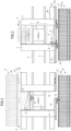
- In 2 is on the opposite side of the pick-up points 17 of the transport path 4 another staging device 6b indicated in phantom, whose pick-up points 17 can be reached by the mounting head 12 mounted on the guide arm 9.
- the additional supply device 6b can be configured so narrowly that it fits between the side walls 7 and can be arranged close to the placement area 5, so that the distances covered by the placement head 12 are reduced.
Description
Die Erfindung betrifft eine Vorrichtung zum Bestücken eines Substrates mit bereitstellbaren elektrischen Bauelementen gemäß dem Oberbegriff von Anspruch 1.The invention relates to a device for equipping a substrate with electrical components that can be provided according to the preamble of claim 1.
Die Erfindung bezieht sich insbesondere auf eine Vorrichtung zum Bestücken eines Substrats mit bereitstellbaren elektrischen Bauelementen mit mindestens einem Bestückkopf zum Handhaben der Bauelemente, wobei das Substrat in einer Längsrichtung durch die Vorrichtung transportierbar und in einem Bestückbereich der Vorrichtung fixierbar ist,
- wobei die Bauelemente in zumindest einem Abholbereich der Vorrichtung breitstellbar sind, wobei der Bestückkopf zwischen dem Abholbereich und dem Bestückbereich verfahrbar ist, wobei ein sich in der Längsrichtung erstreckender Führungsarm an einem Grundkörper der Vorrichtung quer zur Längsrichtung verschiebbar gelagert ist, wobei der Führungsarm eine sich in der Längsrichtung erstreckende zwischen seinen Stirnenden durchgehende lineare erste Führungsbahn aufweist, in die dazu kompatible Linearlager des Bestückkopfs eingreifen,
- wobei am Grundkörper zu beiden Seiten des Längenbereichs des Führungsarms zwei Führungselemente mit zu der ersten Führungsbahn kompatiblen zweiten Führungsbahnen gelagert sind, die sich außerhalb des Bestückbereichs in gleicher Höhenlage wie die Führungselemente parallel zur ersten Führungsbahn erstrecken,
- wobei der Führungsarm in eine definierte Übergabeposition verschiebbar ist, in der die erste und zumindest eine der beiden zweiten Führungsbahnen miteinander fluchten,
- wobei die jeweils einander zugewandten Enden der Führungsbahnen unmittelbar aneinander angrenzen und wobei der Bestückkopf über das Ende des Führungsarms hinaus auf die angrenzende zweite Führungsbahn verschiebbar ist.
- wherein the components can be spread in at least one collection area of the device, wherein the placement head can be moved between the collection area and the placement area, wherein a guide arm extending in the longitudinal direction is mounted on a base body of the device so that it can be displaced transversely to the longitudinal direction, the guide arm having a the longitudinally extending continuous linear first guide track between its front ends, in which compatible linear bearings of the placement head engage,
- two guide elements with second guide tracks that are compatible with the first guide track being mounted on the base body on both sides of the longitudinal area of the guide arm, which extend parallel to the first guide track outside of the placement area at the same height as the guide elements,
- wherein the guide arm can be moved into a defined transfer position in which the first and at least one of the two second guideways are aligned with one another,
- wherein the respective ends of the guideways facing each other directly adjoin one another and wherein the placement head can be displaced beyond the end of the guide arm onto the adjacent second guideway.
Eine derartige Vorrichtung ist durch die
Der eine Vielzahl von Bauelementen aufnehmende Bestückkopf ist über das Ende des Führungsarms hinaus auf das Führungselement verschiebbar ist. In diesem zusätzlichen Verschiebebereich des Bestückkopfs und dem vom Führungsarm überdeckten Bereich und sind durchgehend Abholstellen für die Bauelemente angeordnet. Auf der gegenüberliegenden Längsseite der Vorrichtung sind weitere Abholstellen angeordnet, die mittels eines weiteren Führungsarms und eines weiteren Bestückkopfes erreicht werden, wobei jeweils ein Bestückkopf einem der Führungsarme zugeordnet ist.The placement head, which accommodates a large number of components, can be displaced beyond the end of the guide arm onto the guide element. In this additional displacement area of the placement head and the area covered by the guide arm, collection points for the components are arranged throughout. Further pick-up points are arranged on the opposite longitudinal side of the device, which can be reached by means of a further guide arm and a further placement head, with one placement head being assigned to one of the guide arms.
Der Erfindung liegt die Aufgabe zugrunde, bei geringem baulichem Mehraufwand der Vorrichtung die Bestückleistung zu erhöhen.The invention is based on the object of increasing the pick and place performance with little additional structural outlay for the device.
Die Aufgabe wird durch eine Vorrichtung mit den Merkmalen von Anspruch 1 gelöst. Weiterbildungen sind den abhängigen Ansprüchen zu entnehmen.The object is solved by a device with the features of claim 1. Further developments can be found in the dependent claims.
Die Aufgabe wird insbesondere dadurch gelöst, dass in den Führungsbahnen ein weiterer, unabhängig von dem anderen Bestückkopf verschiebbarer Bestückkopf geführt ist und dass zumindest zeitweise einer der beiden Bestückköpfe ausschließlich an der ersten Führungsbahn und der andere ausschließlich an einer der zweiten Führungsbahnen gelagert ist.The object is achieved in particular in that another placement head that can be moved independently of the other placement head is guided in the guideways and that at least temporarily one of the two placement heads is mounted exclusively on the first guideway and the other exclusively on one of the second guideways.
Die ersten und zweiten Führungsbahnen bilden ein gemeinsames Führungssystem für die beiden Bestückköpfe, die weitgehend unabhängig voneinander agieren können. Es ist allgemein üblich, derartige Bestückköpfe so auszubilden, dass sie eine Vielzahl von Bauelementen aufnehmen können. Dadurch ist es z.B. möglich, einen der beiden Bestückköpfe auf einer der beiden stationären zweiten Führungsbahnen Bauelemente abholen zu lassen, während der andere mit dem Führungsarm über die Leiterplatte verfährt, um diese mit Bauelementen zu bestücken.The first and second guideways form a common guide system for the two placement heads, which can act largely independently of one another. It is common practice to design placement heads of this type in such a way that they can accommodate a large number of components. This makes it possible, for example, to have one of the two placement heads pick up components on one of the two stationary second guideways, while the other moves the guide arm over the circuit board in order to place components on it.
Danach wird der Führungsarm in die Übergabeposition verschoben, in der die Führungsbahnen miteinander fluchten. Der auf der stationären zweiten Führungsbahn befindliche Bestückkopf kann nun auf die mobile erste Führungsbahn des Führungsarms verschoben werden und auf dieser zugeordnete weitere Bauelemente abholen. Gleichzeitig kann der auf dem Führungsarm gelagerte Bestückkopf auf die gegenüberliegende zweite Führungsbahn verschoben werden und dort Bauelemente abholen. Durch die gleichzeitige Abhol- und Bestücktätigkeit der Bestückköpfe kann mit geringem baulichen Mehraufwand die Stückleistung der Vorrichtung erheblich gesteigert werden.Thereafter, the guide arm is moved to the transfer position in which the guideways are aligned with one another. The placement head located on the stationary second track can now be moved to the mobile first track of the guide arm and pick up additional components assigned to it. At the same time, the placement head mounted on the guide arm can be moved to the opposite, second guide track and pick up components there. Due to the simultaneous pick-up and placement activity of the placement heads, the piece output of the device can be significantly increased with little additional structural effort.
Die Führungselemente am Grundkörper sind in der Längsrichtung verschiebbar gelagert, wobei nach dem Entfernen des Führungsarms aus dem Bereich der Führungselemente diese in einen Überlappungsbereich mit der ersten Führungsbahn verschiebbar sind.The guide elements on the base body are mounted so that they can be displaced in the longitudinal direction, and after the guide arm has been removed from the region of the guide elements, these can be displaced into an overlapping region with the first guide track.
Die Verschiebbarkeit der Führungselemente in der Längsrichtung kann z.B. mittels üblicher Spindelantriebe und Linearführungen realisiert werden. Dadurch wird der dem jeweiligen Führungselement zugeordnete Abholbereich vom äußeren Ende bis zur Maschinenmitte erheblich vergrößert, so dass der Bestückkopf vollständig mit Bauelementen belegt werden kann, ohne noch Bauelemente vom Führungsarm aus abholen zu müssen. Die Abholtätigkeit und die Bestücktätigkeit können zeitlich gleichmäßig auf die beiden Bestückköpfe verteilt und deren Leistung entsprechend gesteigert werden. In Bezug auf die Übergabe des Bestückkopfs zwischen dem Führungsarm und den Führungselementen sind diese trotz ihrer Längsverschiebbarkeit als stationär zu verstehen.The displaceability of the guide elements in the longitudinal direction can be implemented, for example, using standard spindle drives and linear guides. As a result, the pick-up area assigned to the respective guide element is significantly increased from the outer end to the middle of the machine, so that the placement head can be completely occupied with components without having to pick up components from the guide arm. The pick-up activity and the placement activity can be distributed evenly over the two placement heads and their performance can be increased accordingly. With regard to the transfer of the placement head between the guide arm and the guide elements, these are to be understood as stationary despite their longitudinal displaceability.
In diesem Zusammenhang wird die erste Führungsbahn als mobile Führungsbahn verstanden, da sie zusammen mit dem Führungsarm beweglich, also mobil ist. Die beiden zweiten Führungsbahnen werden auch als stationäre Führungsbahnen verstanden, da sie zwar in Längsrichtung verschiebbar sind, aber dennoch als ortsfest bezeichnet werden können.In this context, the first guide track is understood as a mobile guide track, since it can be moved together with the guide arm, that is to say it is mobile. The two second guideways are also understood as stationary guideways, since although they can be displaced in the longitudinal direction, they can still be described as stationary.
Die Führungselemente können über das äußere Ende des Grundkörpers hinaus verschiebbar sein.The guide elements can be displaced beyond the outer end of the base body.
Durch diese Weiterbildung kann der Abholbereich für die Bauelemente in der Längsrichtung verbreitert werden.As a result of this further development, the pick-up area for the components can be widened in the longitudinal direction.
Die beiden zweiten Führungsbahnen beider Führungselemente können zueinander fluchtend angeordnet sein.The two second guide tracks of both guide elements can be arranged in alignment with one another.
Durch die Weiterbildung ist es möglich, dass die beiden Führungselemente in die Maschinenmitte bis zum Zusammenstoßen bzw. bis zu einem Kontakt verschoben werden können und die Bestückköpfe auch unmittelbar von einem auf das andere Führungselement verfahren können.The further development makes it possible for the two guide elements to be moved into the center of the machine until they collide or make contact, and the placement heads can also move directly from one guide element to the other.
Die Länge der beiden zweiten Führungsbahnen kann jeweils größer sein als die halbe Länge der ersten Führungsbahn, wobei die beiden Führungselemente wahlweise bis über die Mitte der ersten Führungsbahn verschiebbar sein können.The length of the two second guideways can each be greater than half the length of the first guideway, it being possible for the two guide elements to be displaceable over the middle of the first guideway as desired.
Durch diese Weiterbildung können die Bauelemente auch im Mittelbereich der Vorrichtung durchgehend aneinander gereiht und überlappend von beiden Führungselementen aus abgeholt werden. Insbesondere können in diesem Bereich häufig benötigte Bauelemente angeordnet und von beiden Bestückköpfen nacheinander abgeholt werden.As a result of this further development, the components can also be continuously lined up in a row in the central area of the device and picked up overlapping from both guide elements. In particular, frequently required components can be arranged in this area and picked up one after the other by the two placement heads.
Die Bestückköpfe können an dem Führungsarm und an den Führungselementen jeweils mittels eines elektrischen Linearmotors verschiebbar sein, dessen Spulenteile an den Bestüccköpfen angebracht sind und dessen Magnetteile in gleichmäßiger Verteilung entlang dem Führungsarm und den Führungselementen angeordnet sind.The placement heads can be moved on the guide arm and on the guide elements by means of an electric linear motor, the coil parts of which are attached to the placement heads and the magnetic parts of which are arranged in a uniform distribution along the guide arm and the guide elements.
Durch diese Anordnung der Magnetteile wird erreicht, dass die Übergänge zwischen dem Führungsarm und den Führungselementen so gestaltet sind, als ob es sich um eine durchgehende Magnetbahn handeln würde, so dass das die elektrische Ansteuerung des Spulenteils unabhängig von der Position des Bestückkopfes in gleichbleibender Weise erfolgen kann.This arrangement of the magnetic parts ensures that the transitions between the guide arm and the guide elements are designed as if it were a continuous magnetic path, so that the electrical control of the coil part takes place in a consistent manner, regardless of the position of the placement head can.
Im Abholbereich können Abholstellen der Bauelemente entlang einer äußeren Längsseite der Vorrichtung in der Längsrichtung von einem, in Längsrichtung gesehen, äußeren Endbereich eines der in der Übergabeposition befindlichen Führungselemente durchgehend bis zu einem äußeren Endbereich des anderen Führungselementes aneinander gereiht sein.In the pick-up area, pick-up points for the components can be lined up along an outer longitudinal side of the device in the longitudinal direction, from an outer end area of one of the guide elements located in the transfer position, viewed in the longitudinal direction, to an outer end area of the other guide element.
Diese Weiterbildung ermöglicht die volle Ausnutzung des Abholbereichs der Bauelemente über die volle MaschinenlängeThis further development enables the pick-up area for the components to be fully utilized over the full length of the machine
Auf der dem Abholbereich in Querrichtung gegenüberliegenden Seite des Bestückbereichs kann ein zusätzlicher Abholbereich für die Bauelemente angeordnet sein.An additional pick-up area for the components can be arranged on the side of the pick-and-place area opposite the pick-up area in the transverse direction.
Durch diese Weiterbildung wird die Anzahl der bereitstellbaren Bauelemente weiter gesteigert, wobei die zusätzlichen Abholstellen an einer zusätzlichen Seite vorzusehen sind. Die Bauelemente können nahe an der Leiterplatte angeordnet werden, so dass hier der Bestücckopf kürzere Fahrwege zurücklegen muss. Daher ist es von Vorteil, in diesem Bereich besonders häufig benötigte Bauelemente vorzusehen.This development further increases the number of components that can be provided, with the additional pick-up points having to be provided on an additional side. The components can be arranged close to the printed circuit board, so that the placement head has to cover shorter distances. It is therefore advantageous to provide components that are required particularly frequently in this area.
Es können Führungsmittel für den Führungsarm, der Führungsarm, die Bestückköpfe, die Führungselemente und der Abholbereich auf der dem Bestückbereich gegenüberliegenden Seite der Vorrichtung drehsymmetrisch gedoppelt sein. Dadurch können die Bestückleistung und Anzahl der Abholstellen für die Bauelemente weiter gesteigert werden.Guide means for the guide arm, the guide arm, the placement heads, the guide elements and the pick-up area can be duplicated rotationally symmetrically on the side of the device opposite the placement area. As a result, the placement performance and the number of pick-up points for the components can be further increased.
Ausführungsbeispiele der Erfindung sind in der Zeichnung dargestellt und werden im Folgenden näher erläutert. Es zeigen:
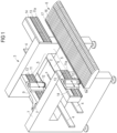
- Figur 1
- eine perspektivische Ansicht einer Vorrichtung zum Bestücken von Substraten mit elektrischen Bauelementen,
Figur 2- eine Draufsicht auf die Vorrichtung nach
Figur 1 in einem anderem Betriebsstadium, und Figur 3- eine Draufsicht auf die Vorrichtung nach
Figur 1 in einem weiteren Betriebsstadium.
- figure 1
- a perspective view of a device for equipping substrates with electrical components,
- figure 2
- a plan view of the device
figure 1 at a different stage of operation, and - figure 3
- a plan view of the device
figure 1 at a further stage of operation.
Nach den
Der Grundkörper 3 weist zu beiden Seiten des Bestückbereichs 5 sich quer zur Längsrichtung x erstreckende, nach oben ragende Seitenwände 7 auf. Eine von diesen ist auf einer der einander zugewandten Innenseiten mit linearen Führungsmitteln 8 und nicht dargestellten Antriebsmitteln für einen sich im Wesentlichen in der Längsrichtung x erstreckenden Führungsarm 9 versehen, der somit in einer waagerechten Querrichtung y senkrecht zur Längsrichtung x verschiebbar ist.The
Der Führungsarm 9 weist auf seiner der Transportstrecke 4 abgewandten flachen Außenseite eine schienenartige lineare erste Führungsbahn 11 für einen in der Längsrichtung waagerecht verschiebbaren Bestückkopf 12 zum Handhaben der Bauelemente auf. Der Verschiebeweg des Führungsarms 9 in der Querrichtung y ist so groß, dass der Bestückkopf 12 zwischen dem Bestückbereich 5 und einer der Bereitstelleinrichtungen 6 verfahrbar ist, die nahe dem Endbereich dieses (Quer-)Verschiebewegs angeordnet ist.The
Der Bestückkopf 12 ist mittels eines elektrische Linearmotors verschiebbar, dessen Magnetteile 13 in der Längsrichtung x am Führungsarm 9 aneinander gereiht sind und dessen Spulenteil dem Bestückkopf 12 zugeordnet ist. Dieser ist in nicht näher dargestellter Weise mit mehreren zueinander parallelen, zylindrisch verteilten, in sich drehbaren Haltern zum Aufnehmen und Absetzen der Bauelemente versehen. Die Halter sind in senkrechter Richtung verschiebbar in einem Rotor gelagert sind, der um eine senkrechte Mittelachse drehbar ist.The
An den einander abgewandten Außenseiten der Seitenwände 7 sind in der Längsrichtung x ragende Trägerteile 3a des Grundkörpers 3 auf der der Bereitstelleinrichtung 6 zugewandten Längsseite der Vorrichtung angesetzt. An den Trägerteilen 3a sind plattenartige Führungselemente 14 gelagert, an denen zweite Führungsbahnen 11a ausgebildet sind, deren Führungsprofil mit der ersten Führungsbahn 11 deckungsgleich ist und die sich in der gleichen Höhenlage parallel zur ersten Führungsbahn 11 erstrecken.On the outer sides of the
Der Führungsarm 9 kann in eine in
Die Bereitstelleinrichtung 6 ist mit flachen, senkrecht stehenden Zuführmodulen 16 versehen, die in der Längsrichtung x aneinander gereiht sind. Die Zuführmodule 16 können mit in Gurtspulen gespeicherten Bauelementen versehen werden, die zu Abholstellen 17 auf der Oberseite der Zuführmodule 16 transportiert werden, wo sie vom Bestückkopf 12 entnommen werden können. Die in der Längsrichtung aneinander gereihten Abholstellen 17 befinden sich in den dem Führungsarm 9 zugewandten Endabschnitten der Zuführmodule 16 im Zugriffsbereich der Halter des Bestückkopfs 12, der sowohl an den Führungselementen 14 als auch an dem in der Übergabeposition befindlichen Führungsarm 9 gelagert sein kann. Die Bereitstelleinrichtung 6 ist so lang, dass sich die Reihe der Zuführmodule 16 bis in den Endbereich der Führungselemente 14 erstreckt, so dass auch die äußersten Abholstellen 17 im Zugriffsbereich des Bestückkopfes 12 liegen, der bis an das freie Ende des jeweiligen Führungselementes 14 verschoben werden kann.The
Der nach
Ein mit dem Bestückkopf 12 baugleicher weiterer Bestückkopf 12 befindet sich auf einem der Führungselemente 14 und nimmt die dort erreichbaren Bauelemente mit seinen Haltern auf. Nach dem Absetzen der Bauelemente auf das Substrat 2 verfährt der Führungsarm 9 in die in
In
Nach
Der Führungsarm 9 mit dem anderen Bestückkopf 12 kann zugleich ungehindert das Substrat 2 bestücken, während das andere Führungselement 14 (in
Nach dem Abholen von Bauelementen aus dem inneren Abholbereich kann das Führungselement 14 in seine äußere Endlage verfahren werden und dort weitere Bauelemente abholen. Nach Beendigung der Bestückvorgänge wird der Führungsarm 9 in die Übergabeposition verfahren. Der betreffende Bestückkopf 12 verfährt nun auf das zuvor passive Führungselement 14 und der an dem zuvor aktiven Führungselement 14 gelagerte Bestückkopf 12 auf den Führungsarm 9, worauf sich die zuvor beschriebenen Vorgänge mit den vertauschten Bestückköpfen 12 und Führungselementen 14 wiederholen.After components have been picked up from the inner pick-up area, the
Wie strichpunktiert angedeutet, können der Führungsarm 9, die Führungsmittel 8, die Trägerteile 3a, die Führungselemente 14, die Bestückköpfe 12 und die Bereitstelleinrichtung 6 um die Mitte der Vorrichtung drehsymmetrisch gedoppelt sein, wodurch sich die Anzahl der Zuführmodule 16 und die Bestückleistung entsprechend erhöht. Durch diese Doppelung werden auf beiden Längsseiten der Vorrichtung Bauelemente bereitgestellt. Durch die gedoppelten Bestückköpfe wird die Bestückleistung weiter gesteigert.As indicated by dash-dotted lines, the
- 22
- Substratsubstrate
- 33
- Grundkörperbody
- 3a3a
- Trägerteilcarrier part
- 44
- Transportstrecketransport route
- 55
- Bestückbereichassembly area
- 66
- Bereitstelleinrichtungprovisioning facility
- 77
- SeitenwandSide wall
- 88th
- Führungsmittelmeans of guidance
- 99
- Führungsarmguide arm
- 1111
- Längsführunglongitudinal guide
- 1212
- Bestückkopfplacement head
- 1313
- Magnetteilmagnetic part
- 1414
- Führungselementguide element
- 1616
- Zuführmodulfeeding module
- 1717
- Abholstellepickup point
Claims (8)
- Device for fitting a substrate (2) with electrical components which can be provided, with- a base plate (3), and with- at least one fitting head (12) for manipulating the components,
wherein- the substrate (2) can be transported in longitudinal direction (x) by the device, and can be fixed in a fitting region (5) of the device,- the components can be provided in at least one collection region (6a) of the device,- the fitting head (12) can be displaced between the collection region (6a) and the fitting region (5),- a guide arm (9) extending in longitudinal direction (x) is displaceably housed, transverse to the longitudinal direction (x), on the base plate (3),- the guide arm (9) has a linear first guide track (11) extending in longitudinal direction (x) passing between its end faces, in which track linear bearings of the fitting head (12), compatible therewith, engage,- two guide elements (14) with second guide tracks (11a) compatible with the first guide track (11) are housed on both sides of the longitudinal region of the guide arm (9) at the base plate (3), which elements extend parallel to the first guide track (11) outside of the fitting region (5) at the same height as the first guide track (11) of the guide element (14),- the guide arm (9) can be displaced in a defined hand-over position in which the first guide track (11) and the two second guide tracks (11a) are flush to one another,- each of which directly adjoin ends of the first and second guide tracks (11, 11a) facing one another, and wherein- the fitting head (12) can be displaced over the end of the guide arm (9) onto the adjoining second guide track (11a), wherein- a further fitting head (12), which can be displaced independently of the other fitting head (12), is guided into the guide tracks (11, 11a),- an operating state is possible in which at least occasionally one of the two fitting heads (12) is housed exclusively on the first guide track (11) and the other is housed exclusively on one of the second guide tracks (11a), and wherein in another operating state, in which the guide arm is in the hand-over position, the fitting head (12) located on the second guide track (11a) can be shifted onto the first guide track (11) of the guide arm and simultaneously the fitting head housed on the guide arm can be shifted onto the opposing second guide track;- the guide elements (14) are displaceably housed in the longitudinal direction (x) at the base plate (3), and- after removing the guide arm (9) from the region of the guide elements (14), these are shifted into an overlap region with the first guide track (11). - Device according to claim 1, characterised in that the guide elements (14) can be shifted over the outer end of the base plate (3).
- Device according to claim 1 or 2, characterised in that the two second guide tracks (11a) of both guide elements (14) are arranged flush to one another.
- Device according to one of claims 1 to 3, characterised in that- the length of each of the two second guide tracks (11a) is greater than half the length of the first guide track (11), and that- the two guide elements (14) can optionally be shifted as far as the centre of the first guide track (11).
- Device according to one of the preceding claims, characterised in that the fitting heads (12) can each be displaced on the guide arm (9) and on the guide elements (14) by means of an electric linear motor, the coil parts of which are attached to the fitting heads (12) and the magnetic parts of which (13) are arranged in uniform distribution along the guide arm (9) and the guide elements (14).
- Device according to one of the preceding claims, characterised in that, in the collection region (6a), collection points (17) of the components are linked along an outer longitudinal side of the device, from an outer end region of one of the guide elements (14) located in the hand-over position, viewed in longitudinal direction (x), as far as an outer end region of the other guide element (14).
- Device according to one of the preceding claims, characterised in that an additional collection region (6b) is arranged for the components on the side of the fitting region (5) opposite the collection region (6a) in transverse direction (y).
- Device according to claim 7, characterised in that guide means (8) for the guide arm (9), the guide arm (9), the fitting heads (12), the guide elements (14) and the collection region 6a are duplicated, in rotationally-symmetrical manner, on the side of the device opposite the fitting region (5).
Applications Claiming Priority (1)
| Application Number | Priority Date | Filing Date | Title |
|---|---|---|---|
| DE102017104475.2A DE102017104475B4 (en) | 2017-03-03 | 2017-03-03 | Device for equipping substrates with electrical components |
Publications (2)
| Publication Number | Publication Date |
|---|---|
| EP3370494A1 EP3370494A1 (en) | 2018-09-05 |
| EP3370494B1 true EP3370494B1 (en) | 2023-07-19 |
Family
ID=61256769
Family Applications (1)
| Application Number | Title | Priority Date | Filing Date |
|---|---|---|---|
| EP18158029.1A Active EP3370494B1 (en) | 2017-03-03 | 2018-02-22 | Device for populating substrates with electrical components |
Country Status (2)
| Country | Link |
|---|---|
| EP (1) | EP3370494B1 (en) |
| DE (1) | DE102017104475B4 (en) |
Family Cites Families (3)
| Publication number | Priority date | Publication date | Assignee | Title |
|---|---|---|---|---|
| DE10016130C1 (en) * | 2000-03-31 | 2001-08-23 | Siemens Ag | Device for equipping substrates with electrical components |
| DE102012009439B4 (en) * | 2012-05-11 | 2015-09-24 | Mimot Gmbh | Device for equipping substrates with electrical components |
| DE102012025425B4 (en) * | 2012-12-21 | 2017-12-14 | Mimot Gmbh | Device for equipping substrates with electrical components |
-
2017
- 2017-03-03 DE DE102017104475.2A patent/DE102017104475B4/en active Active
-
2018
- 2018-02-22 EP EP18158029.1A patent/EP3370494B1/en active Active
Also Published As
| Publication number | Publication date |
|---|---|
| EP3370494A1 (en) | 2018-09-05 |
| DE102017104475A1 (en) | 2018-09-06 |
| DE102017104475B4 (en) | 2018-12-13 |
Similar Documents
| Publication | Publication Date | Title |
|---|---|---|
| WO1999059389A2 (en) | Facility for fitting component carriers with electric components | |
| AT394019B (en) | CONVEYOR | |
| WO1998037744A1 (en) | Device for producing electrical components | |
| EP2073620A1 (en) | Substrate transport device for a filling machine | |
| DE102008010236B4 (en) | Device for transporting substrates in a placement machine, automatic placement machine and method for transporting substrates | |
| DE102012009439B4 (en) | Device for equipping substrates with electrical components | |
| DE3902063C2 (en) | ||
| WO2000003837A1 (en) | Device for the automated tooling of works | |
| EP3370494B1 (en) | Device for populating substrates with electrical components | |
| EP3548215B1 (en) | Method for bonding large modules and corresponding bonding arrangement | |
| EP0497128B1 (en) | Device for equipping of circuit boards | |
| EP1769661B1 (en) | Loading system and method for loading substrates with electrical components | |
| DE19857331C1 (en) | Cooling device for automatic placement machines | |
| EP1512316A1 (en) | Assembly system and method for assembling components onto substrates | |
| DE10016130C1 (en) | Device for equipping substrates with electrical components | |
| EP0150662A2 (en) | Apparatus for loading and unloading machines for working on printed circuit boards, especially component-cladding machines | |
| DE19707267A1 (en) | Automatic equipping machine for circuit board electrical components | |
| CH674504A5 (en) | ||
| DE102007017258B4 (en) | Feeding of area magazines by means of a transport path of a printed circuit board transport system with multiple transport routes | |
| DE102021119314B3 (en) | Placement machine and placement system with a rail system for two-dimensional movement of a robot device for exchanging component feed devices, production line and production plant for manufacturing electronic assemblies, method for fitting component carriers | |
| WO2008071280A1 (en) | Pick-and-place robot for placing components on substrates | |
| EP1159858B1 (en) | Device for fitting electric components on substrates | |
| EP1444876B1 (en) | Device and method for equipping substrates with electrical components by means of insertion heads which can be displaced in two parallel guide tracks | |
| EP1785022B1 (en) | Assembling head and method for fitting substrates with electric components | |
| EP1665920B1 (en) | Device for fitting substrates with electrical components |
Legal Events
| Date | Code | Title | Description |
|---|---|---|---|
| PUAI | Public reference made under article 153(3) epc to a published international application that has entered the european phase |
Free format text: ORIGINAL CODE: 0009012 |
|
| STAA | Information on the status of an ep patent application or granted ep patent |
Free format text: STATUS: THE APPLICATION HAS BEEN PUBLISHED |
|
| AK | Designated contracting states |
Kind code of ref document: A1 Designated state(s): AL AT BE BG CH CY CZ DE DK EE ES FI FR GB GR HR HU IE IS IT LI LT LU LV MC MK MT NL NO PL PT RO RS SE SI SK SM TR |
|
| AX | Request for extension of the european patent |
Extension state: BA ME |
|
| STAA | Information on the status of an ep patent application or granted ep patent |
Free format text: STATUS: REQUEST FOR EXAMINATION WAS MADE |
|
| 17P | Request for examination filed |
Effective date: 20190305 |
|
| RBV | Designated contracting states (corrected) |
Designated state(s): AL AT BE BG CH CY CZ DE DK EE ES FI FR GB GR HR HU IE IS IT LI LT LU LV MC MK MT NL NO PL PT RO RS SE SI SK SM TR |
|
| STAA | Information on the status of an ep patent application or granted ep patent |
Free format text: STATUS: EXAMINATION IS IN PROGRESS |
|
| 17Q | First examination report despatched |
Effective date: 20200403 |
|
| STAA | Information on the status of an ep patent application or granted ep patent |
Free format text: STATUS: EXAMINATION IS IN PROGRESS |
|
| 19U | Interruption of proceedings before grant |
Effective date: 20210201 |
|
| 19W | Proceedings resumed before grant after interruption of proceedings |
Effective date: 20211102 |
|
| RAP3 | Party data changed (applicant data changed or rights of an application transferred) |
Owner name: MIMOT GMBH |
|
| RAP3 | Party data changed (applicant data changed or rights of an application transferred) |
Owner name: OTTO KUENNECKE GMBH |
|
| GRAP | Despatch of communication of intention to grant a patent |
Free format text: ORIGINAL CODE: EPIDOSNIGR1 |
|
| STAA | Information on the status of an ep patent application or granted ep patent |
Free format text: STATUS: GRANT OF PATENT IS INTENDED |
|
| INTG | Intention to grant announced |
Effective date: 20230209 |
|
| GRAS | Grant fee paid |
Free format text: ORIGINAL CODE: EPIDOSNIGR3 |
|
| GRAA | (expected) grant |
Free format text: ORIGINAL CODE: 0009210 |
|
| STAA | Information on the status of an ep patent application or granted ep patent |
Free format text: STATUS: THE PATENT HAS BEEN GRANTED |
|
| AK | Designated contracting states |
Kind code of ref document: B1 Designated state(s): AL AT BE BG CH CY CZ DE DK EE ES FI FR GB GR HR HU IE IS IT LI LT LU LV MC MK MT NL NO PL PT RO RS SE SI SK SM TR |
|
| REG | Reference to a national code |
Ref country code: GB Ref legal event code: FG4D Free format text: NOT ENGLISH |
|
| REG | Reference to a national code |
Ref country code: CH Ref legal event code: EP |
|
| REG | Reference to a national code |
Ref country code: DE Ref legal event code: R096 Ref document number: 502018012709 Country of ref document: DE |
|
| REG | Reference to a national code |
Ref country code: IE Ref legal event code: FG4D Free format text: LANGUAGE OF EP DOCUMENT: GERMAN |
|
| REG | Reference to a national code |
Ref country code: LT Ref legal event code: MG9D |
|
| REG | Reference to a national code |
Ref country code: NL Ref legal event code: MP Effective date: 20230719 |
|
| PG25 | Lapsed in a contracting state [announced via postgrant information from national office to epo] |
Ref country code: NL Free format text: LAPSE BECAUSE OF FAILURE TO SUBMIT A TRANSLATION OF THE DESCRIPTION OR TO PAY THE FEE WITHIN THE PRESCRIBED TIME-LIMIT Effective date: 20230719 |
|
| PG25 | Lapsed in a contracting state [announced via postgrant information from national office to epo] |
Ref country code: GR Free format text: LAPSE BECAUSE OF FAILURE TO SUBMIT A TRANSLATION OF THE DESCRIPTION OR TO PAY THE FEE WITHIN THE PRESCRIBED TIME-LIMIT Effective date: 20231020 |
|
| PG25 | Lapsed in a contracting state [announced via postgrant information from national office to epo] |
Ref country code: IS Free format text: LAPSE BECAUSE OF FAILURE TO SUBMIT A TRANSLATION OF THE DESCRIPTION OR TO PAY THE FEE WITHIN THE PRESCRIBED TIME-LIMIT Effective date: 20231119 |
|
| PG25 | Lapsed in a contracting state [announced via postgrant information from national office to epo] |
Ref country code: SE Free format text: LAPSE BECAUSE OF FAILURE TO SUBMIT A TRANSLATION OF THE DESCRIPTION OR TO PAY THE FEE WITHIN THE PRESCRIBED TIME-LIMIT Effective date: 20230719 Ref country code: RS Free format text: LAPSE BECAUSE OF FAILURE TO SUBMIT A TRANSLATION OF THE DESCRIPTION OR TO PAY THE FEE WITHIN THE PRESCRIBED TIME-LIMIT Effective date: 20230719 Ref country code: PT Free format text: LAPSE BECAUSE OF FAILURE TO SUBMIT A TRANSLATION OF THE DESCRIPTION OR TO PAY THE FEE WITHIN THE PRESCRIBED TIME-LIMIT Effective date: 20231120 Ref country code: NO Free format text: LAPSE BECAUSE OF FAILURE TO SUBMIT A TRANSLATION OF THE DESCRIPTION OR TO PAY THE FEE WITHIN THE PRESCRIBED TIME-LIMIT Effective date: 20231019 Ref country code: LV Free format text: LAPSE BECAUSE OF FAILURE TO SUBMIT A TRANSLATION OF THE DESCRIPTION OR TO PAY THE FEE WITHIN THE PRESCRIBED TIME-LIMIT Effective date: 20230719 Ref country code: LT Free format text: LAPSE BECAUSE OF FAILURE TO SUBMIT A TRANSLATION OF THE DESCRIPTION OR TO PAY THE FEE WITHIN THE PRESCRIBED TIME-LIMIT Effective date: 20230719 Ref country code: IS Free format text: LAPSE BECAUSE OF FAILURE TO SUBMIT A TRANSLATION OF THE DESCRIPTION OR TO PAY THE FEE WITHIN THE PRESCRIBED TIME-LIMIT Effective date: 20231119 Ref country code: HR Free format text: LAPSE BECAUSE OF FAILURE TO SUBMIT A TRANSLATION OF THE DESCRIPTION OR TO PAY THE FEE WITHIN THE PRESCRIBED TIME-LIMIT Effective date: 20230719 Ref country code: GR Free format text: LAPSE BECAUSE OF FAILURE TO SUBMIT A TRANSLATION OF THE DESCRIPTION OR TO PAY THE FEE WITHIN THE PRESCRIBED TIME-LIMIT Effective date: 20231020 Ref country code: FI Free format text: LAPSE BECAUSE OF FAILURE TO SUBMIT A TRANSLATION OF THE DESCRIPTION OR TO PAY THE FEE WITHIN THE PRESCRIBED TIME-LIMIT Effective date: 20230719 |
|
| PG25 | Lapsed in a contracting state [announced via postgrant information from national office to epo] |
Ref country code: PL Free format text: LAPSE BECAUSE OF FAILURE TO SUBMIT A TRANSLATION OF THE DESCRIPTION OR TO PAY THE FEE WITHIN THE PRESCRIBED TIME-LIMIT Effective date: 20230719 |