EP3370489B1 - Electronic module for an electric motor, in particular a pump unit - Google Patents
Electronic module for an electric motor, in particular a pump unit Download PDFInfo
- Publication number
- EP3370489B1 EP3370489B1 EP18000096.0A EP18000096A EP3370489B1 EP 3370489 B1 EP3370489 B1 EP 3370489B1 EP 18000096 A EP18000096 A EP 18000096A EP 3370489 B1 EP3370489 B1 EP 3370489B1
- Authority
- EP
- European Patent Office
- Prior art keywords
- circuit board
- electronics module
- partition
- contacts
- interface
- Prior art date
- Legal status (The legal status is an assumption and is not a legal conclusion. Google has not performed a legal analysis and makes no representation as to the accuracy of the status listed.)
- Active
Links
- 238000005192 partition Methods 0.000 claims description 75
- 238000007789 sealing Methods 0.000 claims description 27
- 238000009413 insulation Methods 0.000 claims description 7
- 230000033228 biological regulation Effects 0.000 claims description 3
- 230000000630 rising effect Effects 0.000 claims description 2
- 210000004907 gland Anatomy 0.000 claims 1
- 239000002991 molded plastic Substances 0.000 claims 1
- 230000003014 reinforcing effect Effects 0.000 claims 1
- 229910052751 metal Inorganic materials 0.000 description 9
- 239000002184 metal Substances 0.000 description 9
- 230000002093 peripheral effect Effects 0.000 description 8
- 238000001816 cooling Methods 0.000 description 7
- 238000011161 development Methods 0.000 description 7
- 230000018109 developmental process Effects 0.000 description 7
- 238000013461 design Methods 0.000 description 6
- 238000005304 joining Methods 0.000 description 6
- 230000002787 reinforcement Effects 0.000 description 6
- 230000008901 benefit Effects 0.000 description 5
- 239000004020 conductor Substances 0.000 description 5
- 230000000694 effects Effects 0.000 description 5
- 230000006870 function Effects 0.000 description 5
- 238000002347 injection Methods 0.000 description 5
- 239000007924 injection Substances 0.000 description 5
- 230000011664 signaling Effects 0.000 description 5
- 230000007704 transition Effects 0.000 description 5
- 238000003780 insertion Methods 0.000 description 4
- 230000037431 insertion Effects 0.000 description 4
- 239000007788 liquid Substances 0.000 description 4
- 210000002105 tongue Anatomy 0.000 description 4
- 101000836649 Homo sapiens Selenoprotein V Proteins 0.000 description 3
- 102100027056 Selenoprotein V Human genes 0.000 description 3
- 230000005540 biological transmission Effects 0.000 description 3
- 230000015572 biosynthetic process Effects 0.000 description 3
- 238000004891 communication Methods 0.000 description 3
- 230000006378 damage Effects 0.000 description 3
- 230000013011 mating Effects 0.000 description 3
- 229910001092 metal group alloy Inorganic materials 0.000 description 3
- 238000000034 method Methods 0.000 description 3
- 230000008569 process Effects 0.000 description 3
- 230000001681 protective effect Effects 0.000 description 3
- 208000015943 Coeliac disease Diseases 0.000 description 2
- 229910052782 aluminium Inorganic materials 0.000 description 2
- XAGFODPZIPBFFR-UHFFFAOYSA-N aluminium Chemical compound [Al] XAGFODPZIPBFFR-UHFFFAOYSA-N 0.000 description 2
- 230000004323 axial length Effects 0.000 description 2
- 230000001276 controlling effect Effects 0.000 description 2
- 238000010586 diagram Methods 0.000 description 2
- 229920001971 elastomer Polymers 0.000 description 2
- 239000000806 elastomer Substances 0.000 description 2
- 238000010438 heat treatment Methods 0.000 description 2
- 238000012544 monitoring process Methods 0.000 description 2
- 230000001105 regulatory effect Effects 0.000 description 2
- 239000007787 solid Substances 0.000 description 2
- 239000002918 waste heat Substances 0.000 description 2
- 208000027418 Wounds and injury Diseases 0.000 description 1
- 230000006978 adaptation Effects 0.000 description 1
- 238000004458 analytical method Methods 0.000 description 1
- 238000005452 bending Methods 0.000 description 1
- 238000004364 calculation method Methods 0.000 description 1
- 239000003990 capacitor Substances 0.000 description 1
- 230000008859 change Effects 0.000 description 1
- 239000011248 coating agent Substances 0.000 description 1
- 238000000576 coating method Methods 0.000 description 1
- 150000001875 compounds Chemical class 0.000 description 1
- 230000007547 defect Effects 0.000 description 1
- 230000001419 dependent effect Effects 0.000 description 1
- 238000001514 detection method Methods 0.000 description 1
- 238000003745 diagnosis Methods 0.000 description 1
- 238000004512 die casting Methods 0.000 description 1
- 239000003651 drinking water Substances 0.000 description 1
- 235000020188 drinking water Nutrition 0.000 description 1
- 239000000428 dust Substances 0.000 description 1
- 230000005670 electromagnetic radiation Effects 0.000 description 1
- 238000005516 engineering process Methods 0.000 description 1
- 238000011156 evaluation Methods 0.000 description 1
- 125000000524 functional group Chemical group 0.000 description 1
- 230000005484 gravity Effects 0.000 description 1
- 230000017525 heat dissipation Effects 0.000 description 1
- 238000001746 injection moulding Methods 0.000 description 1
- 208000014674 injury Diseases 0.000 description 1
- 238000009434 installation Methods 0.000 description 1
- 230000010354 integration Effects 0.000 description 1
- 230000007257 malfunction Effects 0.000 description 1
- 238000004519 manufacturing process Methods 0.000 description 1
- 239000000463 material Substances 0.000 description 1
- 238000005259 measurement Methods 0.000 description 1
- 230000015654 memory Effects 0.000 description 1
- 238000000465 moulding Methods 0.000 description 1
- 230000007935 neutral effect Effects 0.000 description 1
- 230000003647 oxidation Effects 0.000 description 1
- 238000007254 oxidation reaction Methods 0.000 description 1
- 238000000059 patterning Methods 0.000 description 1
- 230000000149 penetrating effect Effects 0.000 description 1
- 230000035515 penetration Effects 0.000 description 1
- 238000012545 processing Methods 0.000 description 1
- 230000005855 radiation Effects 0.000 description 1
- 230000004044 response Effects 0.000 description 1
- 238000007665 sagging Methods 0.000 description 1
- 238000000926 separation method Methods 0.000 description 1
- 125000006850 spacer group Chemical group 0.000 description 1
- 238000003860 storage Methods 0.000 description 1
- 230000008719 thickening Effects 0.000 description 1
- 238000012546 transfer Methods 0.000 description 1
- XLYOFNOQVPJJNP-UHFFFAOYSA-N water Substances O XLYOFNOQVPJJNP-UHFFFAOYSA-N 0.000 description 1
- 238000004804 winding Methods 0.000 description 1
Images

Classifications
-
- H—ELECTRICITY
- H05—ELECTRIC TECHNIQUES NOT OTHERWISE PROVIDED FOR
- H05K—PRINTED CIRCUITS; CASINGS OR CONSTRUCTIONAL DETAILS OF ELECTRIC APPARATUS; MANUFACTURE OF ASSEMBLAGES OF ELECTRICAL COMPONENTS
- H05K7/00—Constructional details common to different types of electric apparatus
- H05K7/14—Mounting supporting structure in casing or on frame or rack
- H05K7/1422—Printed circuit boards receptacles, e.g. stacked structures, electronic circuit modules or box like frames
- H05K7/1427—Housings
- H05K7/1432—Housings specially adapted for power drive units or power converters
- H05K7/14322—Housings specially adapted for power drive units or power converters wherein the control and power circuits of a power converter are arranged within the same casing
Definitions
- the invention relates generally to an electronics module for mounting on an electric motor, in particular a pump unit, wherein it is preferably intended for mounting on an axial end face of the electric motor.
- the invention relates to an electronics module with electronics for controlling and / or regulating the electric motor, which is accommodated in a housing comprising a lower part and an upper part, in which a first and a second spatial area are present, which are separated from one another by a partition
- a first printed circuit board with power electronic components of a motor control unit for supplying the electric motor, which carries operating voltages of a first voltage level
- a second printed circuit board with system electronic components of a system control unit which carries operating voltages of a second, lower voltage level.
- Electronic modules of the type mentioned are, for example, also from the European patent applications EP 2607707 A1 and EP 2779371 A1 known.
- EP 2607707 A1 It is provided that the electronics are divided into two housing parts, of which a first housing part, called the axial housing, is attached axially to an end face of the electric motor, and the second housing part, called the radial housing, is attached radially to the axial housing so that it is arranged laterally on the electric motor is.
- the radial housing is a solid die-cast part made of a light metal alloy with solid cooling fins that extend circumferentially around the motor housing.
- the radial housing accommodates the power components of a speed controller, which transfer their waste heat to the cooling fins.
- All external lines in particular also the supply line, are introduced into the axial housing through corresponding openings and connected there.
- a division of the electronics according to voltage levels cannot be seen here.
- Each housing part is closed with its own cover. The number of components to be joined and the different joining directions lead to a comparatively complicated assembly process.
- the EP 2779371 A1 provides the axial arrangement of two individual housings of an electronics module axially attached to an electric motor, a first electronics receiving space being present in the upper individual housing and a second electronics receiving space being provided in the lower one.
- the rooms are separated from one another by the bottom of the upper individual housing, which is formed in one piece with the side walls.
- the US 2015/0077955 A1 discloses motor electronics made up of at least two housing parts mounted on top of one another, with a frequency converter in a first housing part and control electronics in a second housing part is located. There is an electrical interface between the housing parts. The purpose of this is to be able to use the same control electronics for frequency converters of different powers.
- a circuit board is provided within the control electronics, the high-voltage components of which are combined in a space that is separated from the rest of the circuit board by a ventilated partition.
- the object of the present invention is to provide an alternative, compact electronic module for an electric motor that is particularly easy to assemble and, at the same time, has a particularly high level of operational reliability and protection provides electric shock.
- sensitive electronic components should have good thermal insulation.
- the partition forms a separate component, i.e. is structurally independent of the upper and lower part. This allows a high degree of design freedom with regard to the form and functional integration and facilitates the axial assembly of the components.
- the partition wall ensures electrical and thermal insulation between the circuit boards.
- the first spatial area together with the first printed circuit board, the partition and the second spatial area together with the second printed circuit board are arranged axially one above the other. The first and second circuit boards are thus parallel to one another and parallel to the partition.
- the lower or first printed circuit board carries power electronic components of the motor control unit, for example a frequency converter for setting the speed of the electric motor, and carries voltages that are harmful to humans during operation, for example a supply voltage (220/230 V, 50 Hz or 110 V / 60 Hz), possibly up to 400V at the intermediate circuit of the frequency converter, preferably only operating voltages which are lower than those of the first circuit board are applied to the upper, ie second circuit board, which carries system electronic components of the system control unit. In particular, these are low voltages or extra-low voltages that are harmless to humans, such as SELV or PELV.
- the harmful operating voltages are consequently arranged in a shielded manner in the lower part of the housing, i.e. not directly accessible to the installer, which means that there is a high degree of operational safety.
- the dividing wall can be coated with metal on its underside facing the first spatial region in order to shield interference radiation from the line electronic components from the system electronic components.
- This coating is preferably grounded in order to divert voltages induced by the electromagnetic radiation.
- the upper part can be shaped like a hood.
- a third spatial area which lies axially above the second spatial area and forms a connection space can be formed, and a removable display and / or operating unit covering the third spatial area can be placed on the upper part.
- all components of the electronic module can be assembled in the same joining direction, namely axially (bottom-up), which considerably simplifies the production of the electronic module 1.
- the remaining part of the upper part preferably remains free from being covered by the display and / or operating unit.
- the third spatial area can be formed in the form of a depression in the end face of the upper part, the bottom forming the bottom of this depression.
- the recess can rise step-like on the sides from the bottom to the front side of the upper part, so that a circumferential step is formed on which the display and / or control unit can rest.
- the display and / or operating unit can be connected to the upper part in a sealing manner. This can preferably be achieved in that on the underside of the display and / or control unit facing the upper part a circumferential seal is present, in particular molded or molded, with which the display and / or control unit sealingly on the step in the recess of the upper part rests.
- connection terminals such as screw or spring terminals of the second circuit board
- connection terminals preferably protrude into the connection space through a base of the upper part, which also covers the second circuit board, so that the second circuit board is protected under the base.
- the bottom of the upper part is preferably formed in one piece with the other walls of the upper part. It is also used for electrical and, above all, thermal insulation between the first and second room areas. It is particularly advantageous if the connection terminals are color-coded so that a function is assigned and the risk of the connections being mixed up is avoided.
- the partition wall forms, as it were, an intermediate floor to the floor of the upper part. This ensures that all current-carrying components and lines of the electronics are inaccessible to the installer.
- the installer To connect electrical lines to the electronics, the installer only has to gain access to the third room area by removing the display and / or operating unit, with the electronic components of the motor control unit and the system control unit behind a protective wall, namely the partition on the one hand and the floor the upper part on the other hand remain hidden.
- this protects the electronics from mechanical damage, for example, and against the penetration of foreign bodies causing short circuits, and on the other hand, it also protects the installer from touching live components, whereby the risk of an electric shock is already reduced because the damaging operating voltages are all on the are located in the lower part of the existing circuit board.
- the second circuit board there can also be at least one potential-free signaling contact on the second circuit board, for example for a collective malfunction message (SSM) or a collective operating message (SBM), to which an external switching voltage between 12V and 240V can be applied by the installer if necessary.
- SSM collective malfunction message
- SBM collective operating message
- the signaling contact can be an NC or NO contact.
- the provision of such reporting contacts is known per se and is often requested by customers.
- the signaling contacts can be relay outputs.
- the lower part is a "rear part” and the upper part is a "front part” in relation to the electric motor and from the point of view of an operator who is in front of the display and / or control unit.
- the second printed circuit board can be held, in particular clipped in, on the partition by means of a latching connection / retaining element. This pre-fixes the second printed circuit board. This takes place suitably on the upper side of the separating element directed towards the upper part.
- the partition wall can preferably have an at least partially circumferential, upright frame on its outer circumference.
- the frame causes the partition wall to be stiffened and thus gives it additional stability.
- the frame preferably extends at right angles from the remaining part of the partition wall, which is parallel to the second printed circuit board, to the upper part.
- the partition wall can have a seal for the lower part.
- the sealing is suitably carried out axially here.
- the partition wall can have a circumferential seal on the edge side on its underside facing the lower part, which seal is in sealing contact with the lower part, in particular rests on the upper side of a peripheral edge of the lower part.
- the seal can be molded or injection-molded directly onto the partition. It therefore does not form a component that has to be installed separately.
- the seal can also overlap the circumferential edge in a form-fitting manner on the inside and / or outside, so that a good fit and a high sealing effect is achieved.
- the partition wall can have a seal to the upper part.
- the sealing is suitably carried out here radially.
- the partition wall can have a circumferential sealing lip on the outside of the frame, which is in sealing contact with the upper part, in particular with the inside of the side walls of the upper part, so that no moisture or liquid penetrates the second area at the transition between the lower and upper part can.
- it can be molded or injection-molded directly onto the partition. It therefore does not form a component that has to be installed separately.
- the seal for the lower part and the seal in particular the sealing lip for the upper part, can merge into one another.
- the transition can only be punctual. In the case of the seal being molded on, this has the advantage that fewer sprues are required through which the elastic molding compound is introduced into the cavity forming the seals.
- the two seals can merge into one another in such a way that they form a single molded seal which then has a first sealing surface for the lower part and a second sealing surface, in particular with a sealing lip, for the upper part. This also allows the number of sprues to form the molded seal to be reduced.
- the sealing lip viewed in cross section, can extend obliquely from the frame to the lower part, whereby a high sealing effect is achieved.
- laterally extending reinforcement structures in the form of rib-like projections can be used on the top and / or bottom to be available. These can preferably have a honeycomb geometry, which also dampens the development and propagation of mechanical vibrations.
- the partition wall has, in its middle / a central area, a support rib, which rises towards the second printed circuit board, for supporting the second printed circuit board. This prevents the second printed circuit board from sagging when a compressive force is applied.
- the support rib expediently extends below along the electrical contacts or connection terminals protruding into the third spatial area, since here, as a rule, a compressive force is exerted on the connection terminals when a line is connected.
- the electronic module according to the invention can have an externally accessible electrical-mechanical interface, which extends into the first spatial area at the rear and is electrically connected to the first printed circuit board, that is to say is assigned to the first voltage level.
- a supply line or a mains plug for supplying the electronic module with a supply voltage (e.g. 110V, 230V, 400V) can be connected to the interface.
- the interface is thus spatially separated from the second and above all from the third room area, and is therefore not accessible when making electrical connections to the electrical connections in the third room area, which also provides protection against dangerous electrical voltage.
- the interface can be designed in the form of a plug or socket contact into which a corresponding socket or plug contact at the end of the supply line, ideally the mains plug, can be plugged.
- the interface can be arranged in a carrier element that is spatially separated from the first and second printed circuit boards. This simplifies assembly, since the first printed circuit board can be inserted into the lower part by purely axial joining.
- a side opening open towards the upper part can be present in a side wall of the lower part, into which the Support element can be used and through which the interface is accessible from the outside.
- the carrier element In its assembled position, the carrier element is suitably at right angles to the first printed circuit board, in particular also to the second printed circuit board.
- the carrier element and the side opening are designed to correspond in their shape and size in such a way that the edge of the carrier element rests positively on the side wall, in particular sealingly, in or on the side opening.
- the carrier element spatially next to, preferably above, the interface.
- the first and second interfaces are thus mechanically connected to one another via the common carrier element.
- the second interface can be used, for example, for the data connection of a second electronic module of a further electric motor driving a turbo machine, so that, for example, a double pump arrangement can be created.
- an external device for example a router of a network, an external sensor, an actuator, a data collector, a computer or another portable read-out and / or control device can be connected to the second interface or to a further second interface in order to receive data from and / or to be transmitted to the electronics module. This list is not exhaustive.
- the second interface or further interface transmits data and / or information unidirectionally or bidirectionally in a wired manner, thus forming a data interface.
- a data connector can be connected here accordingly.
- this does not rule out the fact that the connected device is also supplied with voltage via the second or further interface. This is also possible.
- the second or further interface is / are assigned to the second voltage level and electrically connected to the second printed circuit board.
- the further or further interfaces can also be designed in the form of a plug or socket contact be, into which a corresponding socket or plug contact at the end of a data line, in particular a data plug, can be plugged.
- the electronics module thus has an interface unit spatially separated from the first and second printed circuit boards with at least two adjacent electrical interfaces, in particular plug or socket contacts, which are connected to one another via a common carrier element, a first of the interfaces of the first voltage level for connecting a mains plug and at least one second of the interfaces is assigned to the second voltage level for connecting a data plug.
- the first and second circuit boards are not connected to one another via the interface unit.
- the assignment of the first interface to the first voltage level can take place in such a way that the interface unit or the carrier element is plugged into plug contacts of the first circuit board which protrude into a receiving space for the power plug formed in the carrier element and can be contacted directly by the latter.
- the interface unit thus provides the electrical part of the first interface only after it has been installed.
- the plug contacts are suitably arranged on the edge of the first printed circuit board and protrude through openings in the carrier element into the receiving space, where they can be contacted directly by the mains plug.
- the plug contacts can be, for example, flat contacts, in particular blade contacts, which provide a large contact surface for power transmission.
- the electrical connection between the first interface and the first printed circuit board cannot be made directly, but via one or more cables.
- the ends of the cable or cables can either be soldered directly to the first printed circuit board or electrical contacts of the first interface in the carrier element, or provided with plug-in contacts that are plugged into corresponding mating contacts on the first printed circuit board or the carrier element.
- one end of the cable can also be soldered and the other plugged in by means of plug contacts.
- the mating plug-in contacts do not necessarily have to be present on the edge of the first circuit board, so that a cable connection provides greater flexibility when placing the contacts on the first circuit board.
- the electrical connection of the second and / or further interface assigned to the second voltage level to the second printed circuit board can also take place via individual or a common cable, for example one or two flat ribbon cables.
- a recess can be provided in the partition through which the cable or cables to the second printed circuit board is or are passed.
- the plug contacts on the second printed circuit board are accessible through the recess.
- the plug contacts on the second printed circuit board can be, for example, contact pins, in particular pin strips or plug strips, preferably as SMD (Surface Mounted Device).
- SMD Surface Mounted Device
- the plug contacts are designed as surface contacts on the second printed circuit board and together form a connection area for a board edge connector. This means that no soldered-on components are required on the second printed circuit board in order to make contact with it.
- the connection area of the second printed circuit board can extend over the recess, so that a ribbon cable from the board edge connector, which connects the Connection area contacted at right angles away and can be guided through the recess to the interface unit.
- the carrier element On its rear side facing the first spatial area, the carrier element can also have plug-in contacts which are connected to the electrical contacts of the second or further interface on the front side of the carrier element.
- these plug contacts can also be formed as surface contacts on a circuit board which extends through the carrier element from the front to the rear.
- the second or further interface on the back of the carrier element can also be contacted by a board edge connector.
- the interface unit can thus consist of the carrier element and a printed circuit board which provides the electrical contacts of the at least one second interface.
- the circuit board Apart from conductor tracks and contacts at the end of the conductor tracks, the circuit board preferably does not have, in particular no electrical or electronic components.
- the carrier element can suitably be a molded part made of plastic.
- the circuit board preferably extends into the second and the further interface, so that only this single circuit board is required.
- the circuit board can be Y-shaped so that it provides a common connection area for the second and further interfaces on the rear side, so that both interfaces can be connected to the second circuit board with a single edge connector. This reduces the effort involved in establishing the electrical connection between the interface unit and the second printed circuit board.
- the display and / or operating unit preferably comprises an electronics module and a panel covering this.
- the cover is a design element that gives the electronic module a characteristic appearance both in terms of color and shape and also enables a high degree of flexibility in terms of shape and color design.
- it serves to mechanically fasten the electronic module, which is held on the underside of the panel, in particular can be held via at least one latching connection, the panel in turn being releasably fastened to the upper part, in particular being screw-fastened.
- this secure fastening on the lower part can only take place on one side of the display and / or control unit, with at least one projection on the opposite side which loosely engages in a corresponding recess on the upper part.
- the assembly of the upper part can take place in such a way that the display and / or operating unit is placed on the upper part at an angle, so that the protrusion or protrusions come to rest in the corresponding depression or depressions, whereupon the display and / or the operating unit is pivoted towards the upper part, the pivot axis running through the projection (s) and being fixed to the upper part by means of screws at the end opposite the projection or projections.
- the screwing effort is thus reduced to a minimum.
- the display and / or control unit sensibly does not cover the entire surface of the upper part, but only the upwardly open third spatial area, which can be designed like a trough-shaped recess in the axial face of the upper part, so that the area of the face of the upper part surrounding this recess is an outer surface of the electronics module.
- the display and / or operating unit therefore does not form a cover for the entire electronics module and is also not integrated into such a cover. Rather, it forms a separate module, the lateral dimensions of which are smaller than those of the upper part and which merely represents a cover for part of the upper part.
- the display and / or control unit can be removed while the electric motor is in operation.
- the electric motor or the pump assembly does not have to be put out of operation in order to change the display and / or operating unit.
- the upper part is suitably injection molded from plastic, in particular from a thermally and electrically insulating plastic.
- the lower part is preferably made of die-cast metal, in particular a light metal such as Made of aluminum or a light metal alloy so that it can absorb, conduct and dissipate heat well.
- the partition wall can have a plurality of hollow-cylindrical cable guides which are aligned with openings in the upper part. A cable guided through the openings into the third spatial area is thus also pushed through the cable guides.
- the cable guides offer the possibility of securely attaching an entry nozzle for the cable, so that it is not necessary to attach it to the upper part.
- an internal thread can be present for fastening such an insertion stub in the cable guides in order to receive a corresponding part of the insertion stub which is provided with a corresponding external thread.
- the inlet connection corresponds to a cable screw connection, for example a PG screw connection.
- the electronic module according to the invention is preferably part of the centrifugal pump assembly.
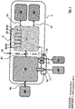
- Fig. 1 shows a schematic diagram of various functional blocks of an electronic module 1 according to the invention and their interconnection.
- the electronics module 1 is for mounting on an electric motor, in particular on a axial end face of an electric motor 40 is provided, which in Fig. 2 is shown.
- the electric motor 40 drives a centrifugal pump (not shown), for example one of a heating system, cooling system, drinking water supply, domestic water heating system, etc.
- the electronics module 1 comprises electronics 10, 20, arranged in a housing 2, 3, for controlling and / or regulating the electric motor 40, which is formed from the main functional groups motor control unit 10 and system control unit 20.
- the motor control unit 10 comprises power electronic components 15 of a speed controller, for example a frequency converter with a voltage intermediate circuit, which are arranged on a first printed circuit board 10a.
- the motor control unit 10 is connected to the windings of the electric motor 40 via an electrical connection 46 and supplies them with electrical power.
- the system unit 10 comprises system electronic components 25, for example one or more microprocessors, program and data memories (RAM, ROM), measurement signal evaluation and / or processing, interface controller, etc., which are arranged on a second printed circuit board 20a.
- the system control unit 20 is control-technically connected to the engine control unit 10 via an electrical connection 45 (cable) and controls it, for example by specifying a target speed, so that it sets a specific operating point on the electric motor 40 or the centrifugal pump.
- the system electronic components 25 are predominantly designed using SMD technology.
- the system control unit 20 has electrical contacts 8a, 8b, 8c, 8d, 8e, which can each be designed as plug, screw or clamp connections and together form a connection area 8.
- Various external devices for example sensors, actuators and / or message lines of a building automation system, can be connected to these contacts 8a, 8b, 8c, 8d, 8e.
- a first contact 8a can form a digital input to which, for example, an external switching element can be connected.
- a second contact 8b can Form an analog input, for example for a differential pressure sensor or a temperature sensor.
- a third contact 8c can form a bus interface for standardized or proprietary communication via a 2, 3 or multi-wire bus with another device, for example a higher-level central controller or with another pump or pumps in the context of double-pump or multi-pump operation.
- one or more potential-free contacts 8d, 8e can be present, which are designed as break contacts or make contacts and report an operating state-dependent status of the electric motor or the pump to the outside. These contacts 8d, 8e are used in particular for connection to a building automation system.
- a contact 8d can output a collective fault message (SSM) and can be closed, for example, when the pump is de-energized or there is no fault. This realizes a potential-free break contact.
- a contact 8e can output a collective operation message (SBM) and, for example, be closed when the pump is energized. This realizes a potential-free normally open contact.
- SSM collective fault message
- SBM collective operation message
- the electronics module 1 also includes a display and / or operating unit 30 for setting the electric motor 40 or the centrifugal pump and for displaying information.
- a display and / or operating unit 30 for setting the electric motor 40 or the centrifugal pump and for displaying information.
- one or more operating elements 35, 36, 37 for interacting with the electronic module 1 on the one hand and / or any display 32 such as a simple LED segment display up to a graphic color display can be present.
- the display 32 can also be touch-sensitive (touch display), so that it combines the functionality of a display and an operating unit.
- the display 32 enables the presentation of information about the operating state, the setting, measured values, errors or other data of the electric motor 40 or the centrifugal pump.
- the display and / or operating unit 30 also forms a function group that is electrically connected to the system control unit 20.
- HMI man-machine interface
- the interface module 62 is optional and provides one or more communication interfaces according to a known standard, for example one or more bus interfaces (CAN, LON, PLR, RS485, Ethernet, etc.) and / or one or more radio interfaces (infrared, Bluetooth®, WLAN, EnOcean®).
- the interface unit 16 is formed by a carrier element 18 which is independent of the first and second printed circuit boards 10a, 20a and on which three interfaces 17, 27, 28 are formed in the exemplary embodiment shown in the figures.
- a mains plug 60 which supplies the electronics module 1 with an electrical voltage, for example 230V, can be connected to the first interface 17 as intended.
- the first interface 17 is electrically connected to the engine control unit 10 and thus transmits electrical power.
- an external sensor 61 for example a volume flow sensor, can be connected to a second interface 27.
- a further electronic module can be connected to a third interface 28, which together with the centrifugal pump of the electronic module 1 forms a double pump unit or a multi-pump unit.
- the second and third interfaces 27, 28 are electrically connected to the system control unit 20. No significant electrical power is transmitted via them, rather data is transmitted here.
- the motor control unit 10, the electric motor 40, the mains plug 60 and the corresponding interface 17 for the mains plug 60 of the interface unit 16 are assigned to a first voltage level which includes the higher operating voltages (110V, 230V, 400V).
- the system control unit 20, the display and / or operating unit 30, the optional interface module 62 and the external sensor 61 including the corresponding interface 28 and also the further interface 27 are assigned to the second voltage level, which only includes extra-low voltages (SELV, PELV) 25V includes.
- the potential-free signal contacts 8d, 8e of the connection area 8 can constitute an exception. If necessary, the installer can connect an external switching voltage between 12V and 240V. These signaling contacts are not assigned to the first or the second voltage level at the factory.
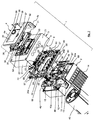
- FIG 2 shows an exploded view of an electronic module 1 according to the invention, which consists of the essential functional units Fig 1 includes. It is clear here that the electronics module 1 is mounted on the axial end face of the electric motor 40, although, according to another embodiment variant, mounting radially on an electric motor 40 is also possible.
- Figures 3 to 5 show enlarged sections of the exploded view Fig. 2 .
- the electronics 10, 20 are accommodated in a housing 2, 3 comprising a lower part 2 and an upper part 3, a first spatial area 5 being present in the lower part 2 and a second spatial area 6 in the upper part 3, which are separated from one another by a partition 50 are.
- the partition 50 forms a separate component.
- a first printed circuit board 10a with power electronic components 15, 15a of the motor control unit 10 for supplying the electric motor 40, which carries operating voltages of the first voltage level, is located in the first spatial area 5.
- the first printed circuit board 10a is screwed into the lower part 2. Alternatively, it can be locked.
- a second printed circuit board 20a with system electronic components 25 of a system control unit 20, the operating voltages of the second, lower one, is located in the second spatial area 6 Carrying voltage level, which in particular includes voltages (SELV, PELV) of less than 25V.
- the first spatial area 5 together with the first printed circuit board 10a, the partition 50 and the second spatial area 6 together with the second printed circuit board 20a are arranged axially one above the other.
- the components of the first voltage level, which carry or carry voltage that is harmful to humans, are thus protected and inaccessible to the installer in the lower room area 5.
- the partition 50 here forms an electrical, but also at the same time a thermal insulation.
- a third spatial area 7 is also formed axially above the second spatial area 6, which represents a connection area for connecting cables.
- the electrical contacts 8a-8e of the connection area 8 of the second printed circuit board 20a in the form of connection terminals 26 protrude into these through corresponding openings in a base 22 of the upper part 3.
- the bottom 22 also covers the second printed circuit board 20a, in particular almost completely, so that it is also largely inaccessible to the installer, which prevents foreign bodies (dust, metal chips, pieces of wire) from entering the second area 6 when working in the connection area becomes.
- the bottom 22 of the upper part 3 also provides electrical and, above all, thermal shielding between the second and third spatial areas 6, 7.
- connection terminals 8a-8e are designed here as clamp connections for quick and allow easy connection of the cables.
- the connection terminals 8a-8e can preferably be designed to be different in color or be color-coded in order to be able to distinguish them and thus to avoid the risk of mix-ups.
- an interface module 62 is located in the third spatial area 7, which is plugged with a corresponding interface 63 through an opening in the base 22 axially with contacts on the second printed circuit board 20a.
- the interface module 62 is optional and expands the electronics module 1 by connections 64 for connecting various Buses such as CAN, LON, PLR and / or Ethernet.
- connections 64 for connecting various Buses such as CAN, LON, PLR and / or Ethernet.
- radio interfaces such as infrared, Bluetooth, WLAN or EnOcean in order to control the electronics module 1 locally by means of a point-to-point connection or to integrate it into an existing network.
- the display and / or operating unit 30 covering the third spatial area 7 is then detachably placed on the upper part 3.
- This does not cover the entire surface of the upper part 3, but only the upwardly open third spatial area 7, which is designed like a trough-shaped recess in the axial end face of the upper part 3, so that the area of the end face of the upper part 3 surrounding this recess is an outer surface of the electronics module 1 forms.
- the display and / or operating unit 30 thus does not form a cover of the entire electronics module 1 and is also not integrated into such a cover. Rather, it forms a separate module, the lateral dimensions of which are smaller than those of the upper part 3 and which merely represents a cover for part of the upper part 3.
- the display and / or control unit 30 consists of an enclosed electronics 31 and a control panel cover 4 in the form of a panel that is placed on the outside of the electronics 31 and protrudes beyond the latter on the sides, so that in the assembled state it also partially extends over the upper part 3 covers.
- the electronics 31 are arranged on the underside of the panel 4, in particular latched to it.
- the electronics 31 are located in the third spatial area 7.
- a circumferential seal is molded, in particular injection molded, which, when the display and / or operating unit 30 is installed, is in contact with a step formed in the upper part 3 around the third space area 7 to seal.
- the panel 4 has a side leg 4a with which it engages around the upper part 3 at the side. Viewed in cross section, the screen 4 is thus essentially L-shaped.
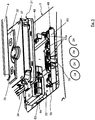
- the electronics 31 in the variant according to FIG Fig. 2 a graphic display 32, in particular a color display for displaying information and / or graphics. Furthermore, it comprises operating elements 35, 37 in the form of two pushbuttons 35, which are arranged symmetrically below the display 32, and a rotatable, in particular rotatable, electrical input element 37, which is arranged centrally below the pushbuttons 35 and carries an operating button 36.
- the input element 37 can additionally or alternatively have a navigation function (joystick), ie it can be moved in the four directions in order to navigate in menus of the software of the system electronics 20.
- the input element 37 can be a potentiometer, but preferably a pulse generator, a multifunctional element or the like, the electrical part 37 of which is accommodated in the electronics 31 and the mechanical part of which protrudes therefrom, at least partially extending through an opening in the panel 4 , and on the other side of the panel 4 carries the attached, here pie-shaped control button 36.
- the panel 4 In its area lying directly above the display 32, the panel 4 has a clear viewing window 33 which covers and protects the display 32.
- the display and / or operating unit 30 can be installed in such a way that it is provided with projections forming retaining tongues 34, see FIG Fig. 5 , inserted into corresponding recesses on an inner side of the third space area 7 obliquely to the bottom 22 of the upper part 3 and then pivoted down together with the panel 4, the support of the projections in the recesses forming a pivot axis.
- the display and / or operating unit 30 can then be attached to the upper part 3 by means of screws 38, which are preferably designed as captive machine screws.
- the screws 38 are screwed into cylindrical screw receptacles 48.
- the screw receptacles 48 have a corresponding internal thread, are measured and are located in cylindrical depressions in the upper part 3.
- the dismantling of the display and / or operating unit 30 can take place in a correspondingly reverse order.
- the electrical connection 47 of the display and / or control unit 30 to the second printed circuit board 20a takes place via a double spring contact and is established automatically when the display and / or control unit 30 is folded onto the upper part 3.
- the double spring contact consists of a first group of contact springs 68 ( Fig. 4 ) on the second printed circuit board 20a are arranged, a group of elongated bridge contacts which are passed through the upper part 3, and a second group of contact springs which are present on the display and / or operating unit 30.
- the number of contact springs 68 of the first group, the number of bridge contacts and the number of contact springs of the second group are identical. How Fig. 4 can be seen, the number is four. However, in another embodiment variant, the numbers of contact springs 68 of the first group, of the bridge contacts and of the contact springs of the second group can also be different.
- the contact springs 68 of the first group protrude towards the upper part 3 and are each spring contacted by one end of one of the bridge contacts.
- the contact springs 68 are designed in the form of essentially Z-shaped bent metal sheets and are compressed by pressure from the direction of the upper part 3.
- the metal sheets can, however, also be shaped in any other way in order to develop a spring effect.
- the bridge contacts are designed in the form of flat contacts and are held firmly in the upper part. This can be done, for example, by overmolding the contacts or by force-fittingly inserting the bridge contacts into corresponding openings in the upper part.
- the bridge contacts can each have a thickening that grants a better hold in the upper part and / or forms a stop when the bridge contacts are pushed in, so that all the bridge contacts are pushed into the upper part identically or aligned with one another.
- the bridge contacts protrude on the side of the upper part 3 opposite the second spatial area 6 in order to contact a contact spring of the second group with their other end.
- the contact springs of the second group are identical to the contact springs 68 of the first group.
- the contact springs 68 and / or the bridge contacts can be gold-plated in order to avoid oxidation.
- a special property of the electronic module according to the invention is that the display and / or operating unit 30 can be removed when the electric motor is in operation without interrupting operation (hot swapping).
- the electric motor 40 or the centrifugal pump driven by it continues to run unchanged according to the setting made. This enables one problem-free and quick exchange of the display and / or operating unit 30 should it ever show a defect.
- the display and / or operating unit 30 is therefore only used for announcing and entering data.
- the new display and / or operating unit 30 seamlessly takes over the task of the previous display and / or operating unit 30, so that no configuration, no data transmission and no other measures are required. to put the new display and / or control unit 30 into operation.
- the electrical contacts which contacted the display and / or operating unit 30 are automatically sealed immediately.
- the electrical contacts to the display and / or operating unit 30 are additionally "dead" so that the installer can be sure that of these, after removal of the display and / or control unit 30 there is no danger to open contacts.
- this sealing has the task of separating the contacts from certain system electronic components 25, so that short-circuiting the contacts does not lead to any damage to the system control unit 20.
- the partition 50 forms a separate component from the upper part 3 and lower part 2, which closes the upper part 3 open towards the lower part 2 and consequently also the lower part 2 open towards the upper part 3. It forms an intermediate floor and is used for electrical and thermal insulation. For this purpose it is injection molded from plastic.
- a plurality of upper guide domes 57 distributed over the circumference are formed on the edge of the side of the partition wall 50 directed towards the upper part 3. When viewed in cross section, these have essentially a T-shape, the middle limb of which is directed towards the edge.
- the middle legs become increasingly shorter, so that at the beginning of the axial merging of the upper part 3 and Partition wall 50, there is a game between the guide domes 57 and the inside of the side walls of the upper part 3, which becomes less and less with increasing merging.
- the side legs of the upper and / or lower guide domes 57, 58 could also become increasingly narrower towards the distal end in order to save material and avoid injury as a result of protruding corners.
- the guide domes 57, 58 can simultaneously serve as spacers, the distance to the length or height of the domes being fixed.
- an opening 44 which is rectangular here by way of example, is formed, through which the electrical connection 45 between the first and second printed circuit boards 10a, 20a is guided.
- the second circuit board 20a extends with a connection area 66 beyond this opening 44, the connection area 66 being formed by surface contacts on the upper and / or lower side of the second circuit board 20a, which can be contacted by means of a circuit board edge connector of the electrical connection 45.
- the second printed circuit board 20a extends with a different sub-area beyond the opening 44.
- a Bluetooth antenna 72 is arranged on this partial area. This placement has the advantage that there is a sufficient distance to parts made of metal and plastic on all sides of the Bluetooth antenna 72, so that the Bluetooth antenna 72 can radiate and receive electromagnetic waves in the best possible way. How also in Fig. 2 As can be seen, the third spatial area 7 in the upper part 7 does not extend beyond the Bluetooth antenna 72. Rather, there is a cavity above the Bluetooth® antenna 72, which merges into the second spatial area 6. The Bluetooth antenna 72 can thus spatially radiate past the display and / or operating unit 30 without any problems.
- the partition wall 50 furthermore has superficial reinforcement structures 54, 54a on its upper and / or lower side in the form of ribs rising at right angles from the surface, which extend laterally, in particular longitudinally or transversely or also in a honeycomb geometry on the surface. They stiffen the partition 50.
- the reinforcement structures also serve to minimize vibrations. Due to the reinforcement structures 54, 54a, the partition 50 can also be made thinner, whereby the weight is reduced.
- the support rib 54a is arranged where the connection terminals 26 of the electrical contacts 8a-8e are located above the second printed circuit board 20a. This prevents the second printed circuit board 20a from bending if a compressive force is exerted in the direction of the second printed circuit board 20a on one of the connection terminals 26 for connecting a line.
- the partition 50 On its outer circumference, the partition 50 has an at least partially, preferably completely, circumferential frame 56 which is formed by a leg extending at right angles to the main region of the partition 50 lying parallel to the second printed circuit board.
- the frame 56 thus extends parallel to the side walls 21 of the upper part 3.
- the frame 56 also provides overall mechanical reinforcement and flexural rigidity.
- the underside of the partition 50 rests in a sealing manner on the peripheral edge 43 directed towards the upper part 3, so that no moisture or liquid can penetrate into the first spatial area 5 at the transition between the lower and upper part 2, 3. The sealing is thus carried out axially here.
- a corresponding seal is provided between the partition 50 and the peripheral edge 43 for sealing.
- the seal In order to design the seal in a positionally secure manner, it is directly on the underside 59 of the partition 50, which is directed towards the lower part 3 Molded on all around the edge (an elastomer molded on).
- the seal is suitably contoured to encompass the peripheral edge 43 in a form-fitting manner on at least one side, preferably the inside.
- the frame 56 has on its outside a protruding, outwardly oriented, circumferential sealing lip which, in the assembled state of the separating element 50, lies tightly against the inside of the side walls 21 of the upper part 3, so that at the transition between the lower and upper part 2, 3 also no moisture or no liquid can penetrate into the second spatial area 6.
- the sealing is thus carried out radially here.
- it can also be molded directly onto the partition 50 or onto the frame 56 (an elastomer injection molded).
- the sealing lip extends obliquely from the outside of the frame 56 in the direction of the lower part 2. This has the effect that the partition 50 is inserted into the upper part while overcoming a lower frictional resistance than the removal of the partition 50 from the upper part 3 results. This increases the sealing effect of the sealing lip.
- Protection class IP 44 is achieved by the sealing lip formed on the outside of the frame 56 and the seal formed on the underside of the partition 50.
- the sealing lip and seal also merge into one another and thus form a cohesive unit, so that only one injection molding step is required to form both seals.
- the partition 50 has a number of adjacent hollow cylindrical geometries 52 which are arranged on the edge. On the one hand, they serve as a cable guide 52 and, in the assembled state, of the partition wall 50 are aligned with openings 24 which are provided in a side wall 21 of the upper part 3.
- the hollow cylindrical geometries 52 have internal threads for screwing in so-called PG screw connections, which guide a cable into the electronics module 1 in a kink-proof manner.
- Bracket-like cable fastenings 53a of a metallic one are in the third spatial region 7 Shield support 53 is provided in order to ground the shield of a cable passed through an opening 24 and the corresponding cable guide 52.
- the partition 50 also has a hood-like shape in an area which is aligned with a corresponding area on the first printed circuit board 10a on which the highest components 15a are arranged, so that these highest components 10a, for example a capacitor and / or a Throttle, extend into the hood-like formation.
- the hood-like formation extends into the second spatial area 6.
- the second printed circuit board 20a has a notch in the area of the hood-like formation.
- the hood-like shape has the advantage that the partition 50 can be arranged closer to the first printed circuit board 10a and thus the overall axial length of the electronic module 1 is shortened.
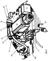
- the electronic module 1 in Fig. 1 comprises an interface unit 16, which is enlarged in FIG Fig. 3 is shown.
- the interface unit 16 is spatially independent of the first and second circuit boards 10a, 20a. It is formed by a carrier element 18 which provides interfaces 17, 27, 28, here three in number. In another embodiment variant, however, there can also be more or fewer interfaces.
- the carrier element 18 is a plastic molded part.
- a mains plug 60 is connected to a first interface 17 and a plug of a sensor cable 29 is connected to a second interface 28.
- An external sensor 61 such as the volume flow sensor 61 in FIG Fig. 1 connected.
- the third interface 27 is uncontacted.
- An electronics module 1 from another pump unit for a double pump or multi-pump application can be connected here.
- the interface in relation to the interface unit 16 with regard to functionality is to be understood as not only an electrical or electro-mechanical, but also a purely mechanical interface that is provided by the interface unit 16.
- the interface unit 16 viewed independently of the other components of the electronic module 1, is designed in such a way that the second and third interfaces 27, 28 are each electrical-mechanical interfaces.
- the interface unit 16 here on the one hand has electrical contacts that are firmly connected to the carrier element 18, and on the other hand the carrier element 18 has a contour around these contacts in order to receive a plug or socket contacting the contacts in a form-fitting manner and thereby mechanically close it lead or hold.
- the first interface 17 provided by the interface unit 16 is only a purely mechanical interface, through which a receiving space is made available for receiving the mains plug 60 in a form-fitting manner.
- the interface unit 16 considered independently of the other components of the electronic module 1, does not provide any electrical contacts of its own here. Electrical contacts 49 belonging to the first interface 17 are, however, present on the first printed circuit board 10a and, when the interface unit 16 is installed, protrude through corresponding openings into the receiving space.
- the first interface 17 thus consists of two functional parts, namely a mechanical part and an electrical part, which only lead together to an electrical-mechanical interface when the interface unit 16 is installed. In the assembled state, the interface unit nevertheless offers three electrical-mechanical interfaces 17, 27, 28 for connecting a plug or a socket.
- the respective electrical and mechanical parts are designed as a unit on the carrier element 18.
- the electrical contacts are each designed here as surface contacts of a printed circuit board 65, which extends from the rear side of the carrier element 18 through an opening into a receiving space of the first and second interfaces 27, 28. The contacting of these surface contacts takes place in the manner of so-called circuit board edge connectors which encompass the circuit board 65 at its edge on both sides.
- the surface contacts of the second interface 27 and the surface contacts of the third interface 27 are formed on a common printed circuit board 65.
- the circuit board 65 is positively and / or by means of locking elements on the Support element 18 held. There are no electrical components on the circuit board 65.
- the surface contacts of the second and third interfaces on the top and / or bottom of the circuit board 65 are only routed to the rear, ie in the direction of the first spatial area 5, where they can also be contacted, in particular plug-in contact, for example also by means of a common board edge connector or two individual board edge connectors.
- the interface unit 16 consists only of the carrier element 18 and the printed circuit board 65
- the first interface 17 is assigned to the first voltage level and is used to connect the electric motor 40 to a mains voltage.
- the second and third interfaces 27, 28 are each assigned to the second voltage level and are primarily used for data transmission, although the connected device, for example a sensor, can also be supplied with low voltage via these interfaces 27, 28.
- the assignment of the first interface 17 to the first voltage level is given by the fact that its electrical contacts 49 are electrically connected to the first printed circuit board 10a and carry voltages of the first voltage level during operation.
- the electrical contacts 49 are designed in the form of flat contacts, see FIG Fig. 3 . They are arranged on the edge of the first printed circuit board 10a and, after the interface unit 16 has been axially joined, protrude into the receiving space for the mains plug 60, which has corresponding fork contacts for mating contact, into which the flat contacts 49 can engage.
- the electrical contacts 49 are formed by three flat contacts for connecting a phase (L), the neutral conductor (N) and the protective conductor (PE) or earth.
- a screw-on eyelet 71 is electrically connected to the flat contact 49 forming the grounding contact and is screwed tightly to the lower part 2 as intended in order to ground it.
- the ground contact of the three flat contacts 49 is also opposite to the other two flat contacts 49 in the direction opposite to the plugging direction of the Mains plug 60 leading. In other words, the length of the ground contact is greater than the length of the other two flat contacts 49, so that when the mains plug 60 is plugged in, the electrical connection to the protective conductor (PE) is established first.
- the assignment of the second and third interfaces 27, 28 to the first voltage level is given by the fact that the second and third interfaces 27, 28 are each connected to the second printed circuit board 20a and only carry low voltages.
- the connection is made here by means of a common ribbon cable which on the one hand makes plug-in contact with the electrical contacts of the second and third interfaces 27, 28 on the rear of the carrier element 18 and on the other hand makes contact, in particular plug-in contact, with the second circuit board 20a.
- a recess 51 is provided in the partition wall 50, see FIG Fig. 4 through which the ribbon cable can be passed during assembly.
- a plug-in area 41 with surface contacts is provided on the second printed circuit board 20a for plugging in the ribbon cable, to which a board edge connector arranged at the end of the ribbon cable can be plugged.
- the recess 51 and the plug-in area 41 are arranged in such a way that the plug-in area lies above the recess 51, so that there is sufficient space to contact the plug-in area 41.
- the board edge connector plugged into the plug-in area 41 lies in the recess 51.
- the carrier element 18 is oriented at right angles to the two printed circuit boards 10a, 20a, so that the interfaces 17, 27, 28 can be contacted in a secantial direction to the electronics module 1, i.e. here also secantially to the motor axis.
- a side opening 13 is provided in a side wall 11 of the lower part 2, in or behind which the interface unit 16 is arranged.
- the side opening 13 is open towards the upper part 2, that is, extends to the peripheral edge 43 of the lower part 2, see Fig. 2 .
- edge 19 of the carrier element 18 and the inner circumferential edge of the side opening 13 in the lower part 2 are suitably configured in a corresponding manner such that the carrier element 18 rests in the side opening 13 in a form-fitting manner.
- a seal can be formed on the edge 19 so that the carrier element 18 or the interface unit 19 lies sealed in the side opening and no moisture can penetrate into the interior of the lower part 2.
- the partition 50 has a screen wall 55 which extends towards the lower part 2. It extends into the side opening 13 of the lower part 2, which it closes towards the upper part 3, leaving that area of the side opening 13 free through which the interfaces 17, 27, 28 of the interface unit 16 are accessible from the outside.
- the screen wall 55 serves to fix the interface unit 16 and seals it off from the partition wall 50.
- the upper part is suitably injection molded from plastic, in particular from a thermally and electrically insulating plastic.
- the lower part is preferably made of metal, in particular a light metal such as aluminum or a light metal alloy, by die casting, so that it can absorb, conduct and release heat well.
- cooling ribs 14 are formed on the lower part 2, which extend laterally and axially parallel to the electric motor 40 on the side facing away from the upper part.
- the lower part 2 has a bottom 12 in which a recess 12a is formed which is intended to receive one or the other power electronic components that generate most of the waste heat. This or these are brought into a thermally conductive connection with the base 12 in order to be able to give off the heat to the cooling fins 14.
- the axial length of the upper part 3 is greater than in the remaining area, which is formed by a recess 23 in the lower part of the upper part.
- the assembly of the electronic module 1 according to the invention takes place "bottom up", i.e. from bottom to top with all components being axially joined.
- the first circuit board 10a is inserted into the first space 5 of the lower part 2, the first circuit board 10a being fastened to the bottom 12 of the lower part 2 by means of screws that are passed through corresponding bores in the first circuit board.
- the circumferential area around these bores is metallized so that the ground potential is brought to the first printed circuit board 10a through the screw connection.
- the interface unit 16 together with the ribbon cable connected to it is then inserted into the side opening 13 of the lower part 2. This is then also screwed to the lower part 2.
- the partition 50 is then placed on the lower part 2 so that the first spatial area 5 is covered.
- the lower guide domes 58 help to align the partition 50 with respect to the lower part 2 in such a way that the underside edge of the partition 50 comes to lie completely on the peripheral edge 43 of the lower part 2. While the partition 50 is in place, the ribbon cable of the interface unit 16 is inserted through the recess 51 and the circuit board connection cable 45 is inserted through the opening 44 in the partition 50.
- Partial assembly of the second printed circuit board 20a on the partition wall 50 now follows.
- the inner surfaces of the upper guide domes 27 facing one another serve here as an axial guide.
- Pre-positioning of the second circuit board 20a is achieved by at least one latching element which engages around the second circuit board 20a and protects it from falling out.
- the ribbon cable of the interface unit 16 and the circuit board connection cable 45 are connected to the second circuit board 20a via the respective circuit board edge connector.
- the upper part 3 is placed on the partition wall 50.
- the outer sides of the upper guide domes 27 serve here as an axial guide.
- the upper part 3 is then screwed to the lower part 2, for which purpose a first group of screw domes 69 extends from the bottom 12 of the lower part to the upper part 3, into which the corresponding screws are screwed.
- the upper part 3 and the partition wall 50 are screwed together by means of screws 39 and cylindrical screw receptacles 42, the screw receptacles 42 being integrally formed on the partition wall 50 and extending through openings 42a in the second printed circuit board 20a.
- the screw receptacles 42 have a central hole into which the corresponding screw 39 can be screwed tightly.
- the second printed circuit board 20a is also screwed to the lower part 2.
- a second group of screw domes 67 is provided which extend from the bottom 12 of the lower part 2 through openings in the partition 50 to the second printed circuit board 20a, in which bores are in alignment with the screw domes 67.
- the peripheral area around these bores is metallized, so that by screwing the second circuit board 20a to the screw domes 67, the earth potential is brought to the second circuit board 20a.
- the metallic shield support 53 which has a tab 70, is fixed at the same time.
- This tab 70 is guided through a recess in the bottom 22 of the upper part 3 and rests on the metallized area of the bore of the second printed circuit board 20a, so that the screen support 53 is also automatically grounded by its fixation.
- a screw 39a is passed through the tab 70 and the second printed circuit board 20a and screwed to one of the screw domes 67.
- the assembly of the display and / or control unit 30 takes place. This is inserted with its retaining tongues 34 into the recesses on the upper part 3 at an angle and then folded with the side leg 4a of the panel 4 opposite the retaining tongues 34 towards the upper part 3, around the third room area 7 to close. The display and / or operating unit 30 is then screwed to the upper part 3 by means of screws 38.
- the assembly of the electronic module according to the invention is particularly simple and quick thanks to the bottom-up principle.
Landscapes
- Engineering & Computer Science (AREA)
- Microelectronics & Electronic Packaging (AREA)
- Casings For Electric Apparatus (AREA)
Description
Die Erfindung betrifft allgemein ein Elektronikmodul für die Montage an einem Elektromotor, insbesondere eines Pumpenaggregats, wobei es vorzugsweise zur Montage an einer axialen Stirnseite des Elektromotors bestimmt ist. Im Besonderen betrifft die Erfindung ein Elektronikmodul mit einer Elektronik zur Steuerung und/ oder Regelung des Elektromotors, die in einem ein Unterteil und ein Oberteil umfassendes Gehäuse aufgenommen ist, in dem ein erster und ein zweiter Raumbereich vorhanden sind, welche durch eine Trennwand voneinander getrennt sind, wobei in dem ersten Raumbereich eine erste Leiterplatte mit leistungselektronischen Bauelementen einer Motorsteuereinheit zur Speisung des Elektromotors einliegt, die Betriebsspannungen einer ersten Spannungsebene trägt, und in dem zweiten Raumbereich eine zweite Leiterplatte mit systemelektronischen Bauelementen einer Systemsteuereinheit einliegt, die Betriebsspannungen einer zweiten, niedrigeren Spannungsebene trägt.The invention relates generally to an electronics module for mounting on an electric motor, in particular a pump unit, wherein it is preferably intended for mounting on an axial end face of the electric motor. In particular, the invention relates to an electronics module with electronics for controlling and / or regulating the electric motor, which is accommodated in a housing comprising a lower part and an upper part, in which a first and a second spatial area are present, which are separated from one another by a partition In the first area there is a first printed circuit board with power electronic components of a motor control unit for supplying the electric motor, which carries operating voltages of a first voltage level, and in the second area there is a second printed circuit board with system electronic components of a system control unit which carries operating voltages of a second, lower voltage level .
Elektronikmodule mit Steuerungs- und/ oder Regelungselektronik für Elektromotoren als Antriebe für Strömungsmaschinen wie Kreiselpumpen oder Lüfter sind allgemein bekannt, beispielsweise aus der deutschen Patentanmeldung
Elektronikmodule der genannten Gattung sind beispielsweise auch aus den europäischen Patentanmeldungen
Die
Die
Aufgabe der vorliegenden Erfindung ist es, ein alternatives kompaktes Elektronikmodul für einen Elektromotor bereitzustellen, das besonders einfach zu montieren ist, gleichzeitig eine besonders hohe Betriebssicherheit und Schutz vor elektrischen Schlägen bietet. Zusätzlich soll eine gute thermische Isolation empfindlicher elektronischer Bauteile gegeben sein.The object of the present invention is to provide an alternative, compact electronic module for an electric motor that is particularly easy to assemble and, at the same time, has a particularly high level of operational reliability and protection provides electric shock. In addition, sensitive electronic components should have good thermal insulation.
Diese Aufgabe wird durch ein Elektronikmodul mit den Merkmalen des Anspruchs 1 gelöst. Vorteilhafte Weiterbildungen sind in den Unteransprüchen angegeben und werden nachfolgend erläutert.This object is achieved by an electronics module with the features of
Bei dem erfindungsgemäßen Elektronikmodul ist vorgesehen, dass die Trennwand ein separates Bauteil bildet, d.h. vom Ober- und Unterteil baulich unabhängig ist. Dies gewährt einen hohen Gestaltungsspielraum hinsichtlich der Form und Funktionsintegration und erleichtert die axiale Montage der Komponenten. Die Trennwand sorgt für eine elektrische und thermische Isolation zwischen den Leiterplatten. Der erste Raumbereich mitsamt der ersten Leiterplatte, die Trennwand und der zweite Raumbereich mitsamt der zweiten Leiterplatte sind axial übereinander angeordnet. Erste und zweite Leiterplatte liegen somit parallel zueinander und parallel zur Trennwand.In the electronic module according to the invention it is provided that the partition forms a separate component, i.e. is structurally independent of the upper and lower part. This allows a high degree of design freedom with regard to the form and functional integration and facilitates the axial assembly of the components. The partition wall ensures electrical and thermal insulation between the circuit boards. The first spatial area together with the first printed circuit board, the partition and the second spatial area together with the second printed circuit board are arranged axially one above the other. The first and second circuit boards are thus parallel to one another and parallel to the partition.
Während die untere bzw. erste Leiterplatte leistungselektronische Bauelemente der Motorsteuereinheit, beispielsweise eines Frequenzumrichters zur Drehzahlstellung des Elektromotors, trägt und im Betrieb für den Menschen schädliche Spannungen führt, beispielsweise eine Versorgungsspannung (220/230V, 50Hz oder 110V/60Hz), gegebenenfalls auch bis zu 400V am Zwischenkreis des Frequenzumrichters, liegen an der oberen, d.h. zweiten Leiterplatte, die systemelektronische Bauelemente der Systemsteuereinheit trägt, vorzugsweise nur Betriebsspannungen an, die niedriger sind als diejenigen der ersten Leiterplatte. Insbesondere handelt es sich dabei um für den Menschen unschädliche Niederspannungen oder Kleinspannungen wie beispielsweise SELV oder PELV. Die schädlichen Betriebsspannungen sind folglich abgeschirmt in dem Unterteil des Gehäuses angeordnet, d.h. nicht unmittelbar dem Installateur zugänglich, wodurch ein hohes Maß an Betriebssicherheit vorliegt.While the lower or first printed circuit board carries power electronic components of the motor control unit, for example a frequency converter for setting the speed of the electric motor, and carries voltages that are harmful to humans during operation, for example a supply voltage (220/230 V, 50 Hz or 110 V / 60 Hz), possibly up to 400V at the intermediate circuit of the frequency converter, preferably only operating voltages which are lower than those of the first circuit board are applied to the upper, ie second circuit board, which carries system electronic components of the system control unit. In particular, these are low voltages or extra-low voltages that are harmless to humans, such as SELV or PELV. The harmful operating voltages are consequently arranged in a shielded manner in the lower part of the housing, i.e. not directly accessible to the installer, which means that there is a high degree of operational safety.
Die Trennwand kann auf ihrer zum ersten Raumbereich gerichteten Unterseite metallisch beschichtet sein, um Störstrahlung der leitungselektronischen Bauelemente von den systemelektronischen Bauelementen abzuschirmen. Vorzugsweise ist diese Beschichtung geerdet, um durch die elektromagnetische Strahlung induzierte Spannungen abzuleiten.The dividing wall can be coated with metal on its underside facing the first spatial region in order to shield interference radiation from the line electronic components from the system electronic components. This coating is preferably grounded in order to divert voltages induced by the electromagnetic radiation.
Das Oberteil kann haubenartig geformt sein. In dem Oberteil kann ein axial über dem zweiten Raumbereich liegender, einen Anschlussraum bildender dritter Raumbereich ausgebildet und auf dem Oberteil eine den dritten Raumbereich abdeckende, abnehmbare Anzeige- und/ oder Bedieneinheit aufgesetzt sein. Somit sind sämtliche Komponenten des Elektronikmoduls in derselben Fügerichtung, nämlich axial montierbar (Bottom-Up), was die Herstellung des Elektronikmoduls 1 erheblich vereinfacht. Vorzugsweise verbleibt der übrige Teil des Oberteils frei von einer Abdeckung durch die Anzeige- und/ oder Bedieneinheit. Der dritte Raumbereich kann in Gestalt einer Vertiefung in der Stirnseite des Oberteils gebildet sein, wobei der Boden den Boden dieser Vertiefung bildet. Geeigneterweise kann sich die Vertiefung an den Seiten vom Boden stufenartig zur Stirnseite des Oberteils erheben, so dass eine umlaufende Stufe gebildet wird, auf der die Anzeige- und/ oder Bedieneinheit aufliegen kann. Die Anzeige- und/ oder Bedieneinheit kann dichtend mit dem Oberteil verbunden sein. Vorzugsweise kann dies dadurch erreicht sein, dass auf der zum Oberteil gerichteten Unterseite der Anzeige- und/ oder Bedieneinheit eine umlaufende Dichtung vorhanden, insbesondere angeformt oder angespritzt ist, mit welcher die Anzeige- und/ oder Bedieneinheit dichtend auf der Stufe in der Vertiefung des Oberteils aufliegt.The upper part can be shaped like a hood. In the upper part, a third spatial area which lies axially above the second spatial area and forms a connection space can be formed, and a removable display and / or operating unit covering the third spatial area can be placed on the upper part. Thus, all components of the electronic module can be assembled in the same joining direction, namely axially (bottom-up), which considerably simplifies the production of the
Vorzugsweise ragen in den Anschlussraum elektrische Anschlüsse, insbesondere Anschlussklemmen wie Schraub- oder Federklemmen der zweiten Leiterplatte durch einen Boden des Oberteils hinein, der die zweite Leiterplatte im Übrigen abdeckt, so dass die zweite Leiterplatte geschützt unter dem Boden liegt. Der Boden des Oberteils ist vorzugsweise einstückig mit den übrigen Wänden des Oberteils ausgebildet. Er dient ebenfalls der elektrischen und vor allem thermischen Isolation zwischen dem ersten und dem zweiten Raumbereich. Von besonderem Vorteil ist es, wenn die Anschlussklemmen farblich codiert sind, so dass eine Funktionszuordnung gegeben ist und die Gefahr einer Vertauschung der Anschlüsse vermieden wird.Electrical connections, in particular connection terminals such as screw or spring terminals of the second circuit board, preferably protrude into the connection space through a base of the upper part, which also covers the second circuit board, so that the second circuit board is protected under the base. The bottom of the upper part is preferably formed in one piece with the other walls of the upper part. It is also used for electrical and, above all, thermal insulation between the first and second room areas. It is particularly advantageous if the connection terminals are color-coded so that a function is assigned and the risk of the connections being mixed up is avoided.
Die Trennwand bildet zum Boden des Oberteils quasi einen Zwischenboden. Es ist dadurch gewährleistet, dass sämtliche stromführenden Bauteile und Leitungen der Elektronik für den Installateur unzugänglich sind. Um elektrische Leitungen an der Elektronik anzuschließen, muss sich der Installateur lediglich Zugang zu dem dritten Raumbereich durch Abnehmen der Anzeige- und/ oder Bedieneinheit verschaffen, wobei die elektronischen Bauelemente der Motorsteuereinheit und der Systemsteuereinheit hinter einer schützenden Wand, nämlich der Trennwand einerseits und dem Boden des Oberteils andererseits verborgen bleiben. Dies schützt zum einen die Elektronik beispielsweise vor mechanischer Beschädigung und vor dem Eindringen Kurzschluss verursachender Fremdkörper, zum anderen aber auch den Installateur vor der Berührung stromführender Bauteile, wobei hier die Gefahr eines elektrischen Schlages ohnehin bereits dadurch reduziert ist, dass die schädlichen Betriebsspannungen allesamt auf der im Unterteil vorhandenen Leiterplatte lokalisiert sind.The partition wall forms, as it were, an intermediate floor to the floor of the upper part. This ensures that all current-carrying components and lines of the electronics are inaccessible to the installer. To connect electrical lines to the electronics, the installer only has to gain access to the third room area by removing the display and / or operating unit, with the electronic components of the motor control unit and the system control unit behind a protective wall, namely the partition on the one hand and the floor the upper part on the other hand remain hidden. On the one hand, this protects the electronics from mechanical damage, for example, and against the penetration of foreign bodies causing short circuits, and on the other hand, it also protects the installer from touching live components, whereby the risk of an electric shock is already reduced because the damaging operating voltages are all on the are located in the lower part of the existing circuit board.
Allerdings sei angemerkt, dass auf der zweiten Leiterplatte auch zumindest ein potentialfreier Meldekontakt, beispielsweise für eine Sammelstörmeldung (SSM) oder eine Sammelbetriebsmeldung (SBM), vorhanden sein kann, an welchen bedarfsweise vom Installateur eine externe Schaltspannung zwischen 12V und 240V angelegt werden kann. Der Meldekontakt kann ein Öffner oder Schließer sein. Die Bereitstellung solcher Meldekontakte ist an sich bekannt und wird von Kundenseite häufig gewünscht. Bei den Meldekontakten kann es sich um Relaisausgänge handeln. Obgleich am Meldekontakt auch eine Schaltspannung über 24V anlegbar ist, wird dadurch das erfindungsgemäße Konzept der funktionalen Trennung der Spannungen und räumlichen Aufteilung auf verschiedene Spannungsebenen nicht durchbrochen, da werksseitig keine Beschaltung der Meldekontakte erfolgt, so dass die zweite Leiterplatte nach wie vor bei Auslieferung des Elektronikmoduls bzw. des Pumpenaggregats mit Elektromotor und Elektronikmodul zum Kunden nur Spannungen der zweiten Spannungsebene trägt, mithin also nur Kleinspannungen.However, it should be noted that there can also be at least one potential-free signaling contact on the second circuit board, for example for a collective malfunction message (SSM) or a collective operating message (SBM), to which an external switching voltage between 12V and 240V can be applied by the installer if necessary. The signaling contact can be an NC or NO contact. The provision of such reporting contacts is known per se and is often requested by customers. The signaling contacts can be relay outputs. Although a switching voltage above 24V can also be applied to the signal contact, this does not break the inventive concept of functional separation of the voltages and spatial division into different voltage levels, since the signal contacts are not wired at the factory, so that the second printed circuit board is still when the electronics module is delivered or the pump unit with electric motor and electronics module to the customer only carries voltages of the second voltage level, therefore only low voltages.
Soweit im Rahmen der vorliegenden Erfindung von einer Spannungsebene die Rede ist, ist damit keine einzelne, feste Spannung gemeint, sondern ein Spannungsbereich. Sinngemäß wird bei den üblicherweise in Motorelektroniken vorkommenden Spannungen erfindungsgemäß differenziert zwischen für den Menschen schädlichen und unschädlichen Spannungen, wobei die Ersteren der ersten Spannungsebene und die letzteren der zweiten Spannungsebene zugehörig sind.As far as a voltage level is mentioned in the context of the present invention, this does not mean a single, fixed voltage, but a voltage range. The same is usually used in engine electronics According to the invention, occurring tensions differentiate between tensions which are harmful to humans and those which are harmless to humans, the former belonging to the first voltage level and the latter belonging to the second voltage level.
Soweit im Rahmen der vorliegenden Erfindung von einem Oberteil und einem Unterteil sowie von einer Ober- und einer Unterseite etc. die Rede ist, so sind damit keine absoluten Richtungsangaben oder Ortsbezüge gemeint, weder bezogen auf die Gravitationskraft noch auf die räumliche Umgebung des Elektronikmoduls, in der die bestimmungsgemäße Montage zu erfolgen hat. Vielmehr ist mit den Präfixen "ober" und "unter" der relative Bezug der entsprechenden Teile zueinander sowie zum Elektromotor angesprochen. Es sei somit klargestellt, dass bei einer Montage des erfindungsgemäßen Elektronikmoduls an einer axialen Stirnseite des Elektromotors mit horizontaler Motorachse, das Unterteil ein "Hinterteil" und das Oberteil "Vorderteil" bezogen auf den Elektromotor und aus Sicht eines Bedieners, der vor der Anzeige und/ oder Bedieneinheit steht, bilden würde.Insofar as an upper part and a lower part as well as an upper and a lower side, etc. are mentioned in the context of the present invention, this does not mean any absolute directional information or location references, neither in relation to the force of gravity nor to the spatial environment of the electronic module, in which has to be installed as intended. Rather, the prefixes “above” and “below” refer to the relative relation of the corresponding parts to one another and to the electric motor. It should thus be made clear that when the electronic module according to the invention is mounted on an axial end face of the electric motor with a horizontal motor axis, the lower part is a "rear part" and the upper part is a "front part" in relation to the electric motor and from the point of view of an operator who is in front of the display and / or control unit.
Zur Vereinfachung der Montage kann die zweite Leiterplatte mittels einer Rastverbindung/ Rückhalteelemente an der Trennwand gehalten, insbesondere eingeclipst sein bzw. werden. Hierdurch wird eine Vorfixierung der zweiten Leiterplatte erreicht. Dies erfolgt geeigneterweise an der zum Oberteil gerichteten Oberseite des Trennelements.To simplify assembly, the second printed circuit board can be held, in particular clipped in, on the partition by means of a latching connection / retaining element. This pre-fixes the second printed circuit board. This takes place suitably on the upper side of the separating element directed towards the upper part.
Vorzugsweise kann die Trennwand an ihrem Außenumfang einen zumindest teilweise umlaufenden, hochstehenden Rahmen aufweisen. Der Rahmen bewirkt eine Versteifung der Trennwand und verleiht ihr somit zusätzlich Stabilität. Vorzugsweise erstreckt sich der Rahmen rechtwinklig vom übrigen, parallel zur zweiten Leiterplatte liegenden Teil der Trennwand zum Oberteil hin.The partition wall can preferably have an at least partially circumferential, upright frame on its outer circumference. The frame causes the partition wall to be stiffened and thus gives it additional stability. The frame preferably extends at right angles from the remaining part of the partition wall, which is parallel to the second printed circuit board, to the upper part.
Um zu verhindern, dass am Übergang zwischen Unter- und Oberteil Feuchtigkeit oder eine Flüssigkeit in den ersten Raumbereich eindringt, kann die Trennwand eine Dichtung zum Unterteil aufweisen. Geeigneterweise ist erfolgt die Abdichtung hier axial.In order to prevent moisture or a liquid from penetrating into the first spatial area at the transition between the lower and upper part, the partition wall can have a seal for the lower part. The sealing is suitably carried out axially here.
Zu diesem Zweck kann die Trennwand auf ihrer zum Unterteil gerichteten Unterseite randseitig eine umlaufende Dichtung aufweisen, die in dichtender Anlage zum Unterteil steht, insbesondere auf der Oberseite einer Umfangskante des Unterteils aufliegt. Um die Dichtung lagesicher auszubilden, kann sie direkt an der Trennwand angeformt oder angespritzt sein. Sie bildet somit kein separat zu montierendes Bauteil. Die Dichtung kann die Umfangskante auch formschlüssig innen und/ oder außen übergreifen, so dass ein guter Sitz und hohe Dichtwirkung erreicht wird.For this purpose, the partition wall can have a circumferential seal on the edge side on its underside facing the lower part, which seal is in sealing contact with the lower part, in particular rests on the upper side of a peripheral edge of the lower part. In order to make the seal secure in position, it can be molded or injection-molded directly onto the partition. It therefore does not form a component that has to be installed separately. The seal can also overlap the circumferential edge in a form-fitting manner on the inside and / or outside, so that a good fit and a high sealing effect is achieved.
Gemäß einer vorteilhaften Weiterbildung kann die Trennwand eine Dichtung zum Oberteil aufweisen. Geeigneterweise ist erfolgt die Abdichtung hier radial. Zu diesem Zweck kann die Trennwand außenseitig am Rahmen eine umlaufende Dichtlippe aufweisen, die in dichtender Anlage zum Oberteil, insbesondere zur Innenseite der Seitenwände des Oberteils steht, so dass am Übergang zwischen Unter- und Oberteil keine Feuchtigkeit bzw. keine Flüssigkeit in den zweiten Raumbereich eindringen kann. Um die Dichtlippe lagesicher auszubilden, kann sie direkt an der Trennwand angeformt oder angespritzt sein. Sie bildet somit kein separat zu montierendes Bauteil.According to an advantageous development, the partition wall can have a seal to the upper part. The sealing is suitably carried out here radially. For this purpose, the partition wall can have a circumferential sealing lip on the outside of the frame, which is in sealing contact with the upper part, in particular with the inside of the side walls of the upper part, so that no moisture or liquid penetrates the second area at the transition between the lower and upper part can. In order to make the sealing lip secure in position, it can be molded or injection-molded directly onto the partition. It therefore does not form a component that has to be installed separately.
Gemäß einer vorteilhaften Weiterbildung können die Dichtung zum Unterteil und die Dichtung, insbesondere die Dichtlippe zum Oberteil in einander übergehen. Der Übergang kann gemäß einer Variante nur punktuell sein. Dies hat im Falle des Anspritzens der Dichtung den Vorteil, dass weniger Angüsse benötigt werden, durch die die elastische Formmasse in die die Dichtungen formende Kavität eingebracht wird. Gemäß einer anderen Variante können die beiden Dichtungen derart in einander übergehen, dass sie eine einzige Formdichtung bilden, die dann eine erste Dichtfläche zum Unterteil und eine zweite Dichtfläche insbesondere mit Dichtlippe zum Oberteil aufweist. Auch hierdurch kann die Anzahl der Angüsse zur Ausbildung der Formdichtung reduziert werden. Die Dichtlippe kann sich, im Querschnitt betrachtet, schräg vom Rahmen zum Unterteil erstrecken, wodurch eine hohe Dichtwirkung erreicht wird.According to an advantageous development, the seal for the lower part and the seal, in particular the sealing lip for the upper part, can merge into one another. According to one variant, the transition can only be punctual. In the case of the seal being molded on, this has the advantage that fewer sprues are required through which the elastic molding compound is introduced into the cavity forming the seals. According to another variant, the two seals can merge into one another in such a way that they form a single molded seal which then has a first sealing surface for the lower part and a second sealing surface, in particular with a sealing lip, for the upper part. This also allows the number of sprues to form the molded seal to be reduced. The sealing lip, viewed in cross section, can extend obliquely from the frame to the lower part, whereby a high sealing effect is achieved.
Um die Trennwand zu versteifen können ober- und/ oder unterseitig sich lateral erstreckende Verstärkungsstrukturen in Gestalt rippenartiger Vorsprünge vorhanden sein. Diese können vorzugsweise in wabenförmiger Geometrie ausgeführt sein, wodurch zudem die Entstehung und Ausbreitung mechanischer Schwingungen gedämpft wird.In order to stiffen the partition wall, laterally extending reinforcement structures in the form of rib-like projections can be used on the top and / or bottom to be available. These can preferably have a honeycomb geometry, which also dampens the development and propagation of mechanical vibrations.
Von besonderem Vorteil ist es, wenn die Trennwand in ihrem mittleren/ einem zentralen Bereich eine sich zur zweiten Leiterplatte erhebende Stützrippe zum Abstützen der zweiten Leiterplatte aufweist. Somit wird verhindert, dass sich die zweite Leiterplatte bei einer Druckkraft nicht durchbiegt. Sinnvollerweise erstreckt sich die Stützrippe unterhalb entlang der in den dritten Raumbereich ragenden elektrischen Kontakte bzw. Anschlussklemmen, da hier in der Regel beim Anschließen einer Leitung eine Druckkraft auf die Anschlussklemmen ausgeübt wird.It is particularly advantageous if the partition wall has, in its middle / a central area, a support rib, which rises towards the second printed circuit board, for supporting the second printed circuit board. This prevents the second printed circuit board from sagging when a compressive force is applied. The support rib expediently extends below along the electrical contacts or connection terminals protruding into the third spatial area, since here, as a rule, a compressive force is exerted on the connection terminals when a line is connected.
Das erfindungsgemäße Elektronikmodul kann eine von außen zugängliche elektrisch-mechanische Schnittstelle aufweisen, die sich rückseitig in den ersten Raumbereich hineinerstreckt und elektrisch mit der ersten Leiterplatte verbunden, mithin also der ersten Spannungsebene zugeordnet ist. An die Schnittstelle kann eine Versorgungsleitung respektive ein Netzstecker zur Versorgung des Elektronikmoduls mit einer Versorgungsspannung (z.B. 110V, 230V, 400V) angeschlossen werden. Die Schnittstelle ist somit vom zweiten und vor allem vom dritten Raumbereich räumlich getrennt, und somit bei der Herstellung elektrischer Verbindungen an den elektrischen Anschlüssen im dritten Raumbereich auch nicht zugänglich, wodurch ebenfalls ein Schutz vor gefährlicher elektrischer Spannung gegeben ist. Die Schnittstelle kann in Gestalt eines Steck- oder Buchsenkontaktes ausgeführt sein, in den ein korrespondierender Buchsen- oder Steckkontakt am Ende der Versorgungsleitung, idealerweise also der Netzstecker ansteckbar ist.The electronic module according to the invention can have an externally accessible electrical-mechanical interface, which extends into the first spatial area at the rear and is electrically connected to the first printed circuit board, that is to say is assigned to the first voltage level. A supply line or a mains plug for supplying the electronic module with a supply voltage (e.g. 110V, 230V, 400V) can be connected to the interface. The interface is thus spatially separated from the second and above all from the third room area, and is therefore not accessible when making electrical connections to the electrical connections in the third room area, which also provides protection against dangerous electrical voltage. The interface can be designed in the form of a plug or socket contact into which a corresponding socket or plug contact at the end of the supply line, ideally the mains plug, can be plugged.
Gemäß einer vorteilhaften Ausführungsvariante kann die Schnittstelle in einem von der ersten und zweiten Leiterplatte räumlich getrennten Trägerelement angeordnet sein. Dies vereinfacht die Montage, da die erste Leiterplatte durch rein axiales Fügen in das Unterteil eingesetzt werden kann.According to an advantageous embodiment variant, the interface can be arranged in a carrier element that is spatially separated from the first and second printed circuit boards. This simplifies assembly, since the first printed circuit board can be inserted into the lower part by purely axial joining.
Um auch das Trägerelement axial zu fügen, kann in einer Seitenwand des Unterteils eine zum Oberteil hin offene Seitenöffnung vorhanden sein, in die das Trägerelement einsetzbar ist und durch die die Schnittstelle von außen zugänglich ist. In seiner montierten Lage liegt das Trägerelement geeigneterweise rechtwinklig zur ersten Leiterplatte, insbesondere auch zur zweiten Leiterplatte.In order to also join the carrier element axially, a side opening open towards the upper part can be present in a side wall of the lower part, into which the Support element can be used and through which the interface is accessible from the outside. In its assembled position, the carrier element is suitably at right angles to the first printed circuit board, in particular also to the second printed circuit board.
Vorzugsweise sind das Trägerelement und die Seitenöffnung in ihrer Form und Größe derart korrespondierend ausgestaltet, dass das Trägerelement randseitig formschlüssig an der Seitenwand, insbesondere dichtend, in oder an der Seitenöffnung an- oder einliegt.Preferably, the carrier element and the side opening are designed to correspond in their shape and size in such a way that the edge of the carrier element rests positively on the side wall, in particular sealingly, in or on the side opening.
Idealerweise ist räumlich neben, vorzugsweise oberhalb der Schnittstelle zumindest eine zweite elektrisch-mechanische Schnittstelle auf dem Trägerelement vorhanden. Die erste und zweite Schnittstelle sind somit über das gemeinsame Trägerelement mechanisch miteinander verbunden. Die zweite Schnittstelle kann beispielsweise dem datentechnischen Anschluss eines zweiten Elektronikmoduls eines weiteren, eine Strömungsmaschine antreibenden Elektromotors dienen, so dass beispielsweise eine Doppelpumpenanordnung geschaffen werden kann. Alternativ kann an die zweite Schnittstelle oder an eine weitere zweite Schnittstelle ein externes Gerät, beispielsweise ein Router eines Netzwerks, ein externer Sensor, ein Aktor, ein Datensammler, ein Computer oder ein anderes tragbares Auslese- und/ oder Bediengerät angeschlossen werden, um Daten von und/ oder zu dem Elektronikmodul zu übertragen. Diese Aufzählung ist nicht abschließend. Insbesondere ist aber erkennbar, dass die zweite Schnittstelle oder weitere Schnittstelle bestimmungsgemäß Daten und/ oder Informationen uni- oder bidirektional kabelgebunden überträgt, mithin also eine Datenschnittstelle bildet. Entsprechend kann hier ein Datenstecker angeschlossen werden. Dies schließt jedoch nicht aus, dass über die zweite oder weitere Schnittstelle auch eine Spannungsversorgung des angeschlossenen Geräts erfolgt. Dies ist ebenfalls möglich.Ideally, there is at least one second electrical-mechanical interface on the carrier element spatially next to, preferably above, the interface. The first and second interfaces are thus mechanically connected to one another via the common carrier element. The second interface can be used, for example, for the data connection of a second electronic module of a further electric motor driving a turbo machine, so that, for example, a double pump arrangement can be created. Alternatively, an external device, for example a router of a network, an external sensor, an actuator, a data collector, a computer or another portable read-out and / or control device can be connected to the second interface or to a further second interface in order to receive data from and / or to be transmitted to the electronics module. This list is not exhaustive. In particular, however, it can be seen that the second interface or further interface, as intended, transmits data and / or information unidirectionally or bidirectionally in a wired manner, thus forming a data interface. A data connector can be connected here accordingly. However, this does not rule out the fact that the connected device is also supplied with voltage via the second or further interface. This is also possible.
Die zweite oder weitere Schnittstelle ist/ sind der zweiten Spannungsebene zugeordnet und elektrisch mit der zweiten Leiterplatte verbunden. Um eine leichte und schnelle Anschließbarkeit zu gewährleisten, können die weitere oder weiteren Schnittstellen ebenfalls in Gestalt eines Steck- oder Buchsenkontaktes ausgeführt sein, in den ein korrespondierender Buchsen- oder Steckkontakt am Ende einer Datenleitung, insbesondere ein Datenstecker einsteckbar ist.The second or further interface is / are assigned to the second voltage level and electrically connected to the second printed circuit board. In order to ensure easy and quick connection, the further or further interfaces can also be designed in the form of a plug or socket contact be, into which a corresponding socket or plug contact at the end of a data line, in particular a data plug, can be plugged.
Das Trägerelement bildet mitsamt der ersten und der zumindest einen zweiten Schnittstelle eine Einheit, mithin eine Schnittstelleneinheit. Gemäß einer vorteilhaften Weiterbildung weist das Elektronikmodul somit eine von der ersten und zweiten Leiterplatte räumlich getrennte Schnittstelleneinheit mit wenigstens zwei nebeneinander liegenden elektrischen Schnittstellen, insbesondere Steck- oder Buchsenkontakten auf, die miteinander über ein gemeinsames Trägerelement verbunden sind, wobei eine erste der Schnittstellen der ersten Spannungsebene zum Anschließen eines Netzsteckers und zumindest eine zweite der Schnittstellen mit der zweiten Spannungsebene zum Anschließen eines Datensteckers zugeordnet ist. Eine Verbindung der ersten und zweiten Leiterplatte miteinander erfolgt über die Schnittstelleneinheit nicht.The carrier element, together with the first and the at least one second interface, forms a unit, hence an interface unit. According to an advantageous development, the electronics module thus has an interface unit spatially separated from the first and second printed circuit boards with at least two adjacent electrical interfaces, in particular plug or socket contacts, which are connected to one another via a common carrier element, a first of the interfaces of the first voltage level for connecting a mains plug and at least one second of the interfaces is assigned to the second voltage level for connecting a data plug. The first and second circuit boards are not connected to one another via the interface unit.
Die Zuordnung der ersten Schnittstelle zur ersten Spannungsebene kann derart erfolgen, dass die Schnittstelleneinheit bzw. das Trägerelement auf Steckkontakte der ersten Leiterplatte gesteckt ist, die in einen im Trägerelement ausgebildeten Aufnahmeraum für den Netzstecker hineinragen und von diesem direkt kontaktierbar sind. Somit stellt die Schnittstelleneinheit den elektrischen Teil der ersten Schnittstelle erst nach ihrer Montage bereit. Der mechanische Teil der ersten Schnittstelle in Gestalt des Aufnahmeraums und gegebenenfalls einer Geometrie für eine sichere und lösbare Verbindung ist dagegen im Trägerelement ausgebildet.The assignment of the first interface to the first voltage level can take place in such a way that the interface unit or the carrier element is plugged into plug contacts of the first circuit board which protrude into a receiving space for the power plug formed in the carrier element and can be contacted directly by the latter. The interface unit thus provides the electrical part of the first interface only after it has been installed. The mechanical part of the first interface in the form of the receiving space and possibly a geometry for a secure and detachable connection, on the other hand, is formed in the carrier element.
Die Steckkontakte sind geeigneterweise randseitig auf der ersten Leiterplatte angeordnet und ragen durch Öffnungen im Trägerelement in den Aufnahmeraum hinein, wo sie direkt von dem Netzstecker kontaktierbar sind. Bei den Steckkontakten kann es sich beispielsweise um Flachkontakte, insbesondere Messerkontakte handeln, die eine große Kontaktfläche zur Leistungsübertragung bereitstellen. Durch ein axiales bauliches Zusammenfügen der Schnittstelleneinheit und des Unterteils kann somit gleichzeitig direkt die elektrische Verbindung zwischen der ersten Schnittstelle und der ersten Leiterplatte hergestellt werden.The plug contacts are suitably arranged on the edge of the first printed circuit board and protrude through openings in the carrier element into the receiving space, where they can be contacted directly by the mains plug. The plug contacts can be, for example, flat contacts, in particular blade contacts, which provide a large contact surface for power transmission. By axially joining the interface unit and the lower part together, the electrical connection between the first interface and the first printed circuit board can thus be established directly at the same time.
Alternativ kann die elektrische Verbindung zwischen der ersten Schnittstelle und der ersten Leiterplatte nicht direkt, sondern über ein oder mehrere Kabel erfolgen. So können die Enden des Kabels oder der Kabel entweder direkt mit der ersten Leiterplatte bzw. elektrischen Kontakten der ersten Schnittstelle im Trägerelement verlötet oder mit Steckkontakten versehen sein, die in entsprechende Gegensteckkontakte an der ersten Leiterplatte bzw. am Trägerelement einzustecken bzw. eingesteckt sind. Ferner kann auch ein Kabelende gelötet und das andere mittels Steckkontakten gesteckt sein. Die Gegensteckkontakte müssen dabei nicht unbedingt randseitig auf der ersten Leiterplatte vorhanden sein, so dass durch eine Kabelverbindung eine höhere Flexibilität bei der Platzierung der Kontakte auf der ersten Leiterplatte gegeben ist.Alternatively, the electrical connection between the first interface and the first printed circuit board cannot be made directly, but via one or more cables. For example, the ends of the cable or cables can either be soldered directly to the first printed circuit board or electrical contacts of the first interface in the carrier element, or provided with plug-in contacts that are plugged into corresponding mating contacts on the first printed circuit board or the carrier element. Furthermore, one end of the cable can also be soldered and the other plugged in by means of plug contacts. The mating plug-in contacts do not necessarily have to be present on the edge of the first circuit board, so that a cable connection provides greater flexibility when placing the contacts on the first circuit board.
Auch die elektrische Verbindung der der zweiten Spannungsebene zugeordneten zweiten und/ oder weiteren Schnittstelle mit der zweiten Leiterplatte kann über einzelne oder ein gemeinsames Kabel, beispielsweise ein oder zwei Flachbandkabel erfolgen.The electrical connection of the second and / or further interface assigned to the second voltage level to the second printed circuit board can also take place via individual or a common cable, for example one or two flat ribbon cables.
Um die elektrische Verbindung von der Schnittstelleneinheit zur zweiten Leiterplatte zu ermöglichen, kann in der Trennwand eine Ausnehmung vorhanden sein, durch die das oder die Kabel zur zweiten Leiterplatte hindurchgeführt ist bzw. sind. In dieser Ausführungsvariante sind somit die Steckkontakte auf der zweiten Leiterplatte durch die Ausnehmung zugänglich.In order to enable the electrical connection from the interface unit to the second printed circuit board, a recess can be provided in the partition through which the cable or cables to the second printed circuit board is or are passed. In this embodiment variant, the plug contacts on the second printed circuit board are accessible through the recess.
Bei den Steckkontakten auf der zweiten Leiterplatte kann es sich beispielsweise um Kontaktstifte, insbesondere Stift- oder Steckerleisten, vorzugsweise als SMD (Surface Mounted Device) handeln. Von besonderem Vorteil ist es jedoch, wenn die Steckkontakte als Oberflächenkontakte auf der zweiten Leiterplatte ausgebildet sind und gemeinsam einen Anschlussbereich für einen Platinenrandstecker bilden. Somit werden keine aufgelöteten Bauteile auf der zweiten Leiterplatte benötigt, um diese zu kontaktieren. Idealerweise kann sich die zweite Leiterplatte mit ihrem Anschlussbereich über die Ausnehmung hinweg erstrecken, so dass ein Flachbandkabel vom Platinenrandstecker, der den Anschlussbereich kontaktiert rechtwinklig weg- und durch die Ausnehmung zur Schnittstelleneinheit hingeführt werden kann.The plug contacts on the second printed circuit board can be, for example, contact pins, in particular pin strips or plug strips, preferably as SMD (Surface Mounted Device). However, it is particularly advantageous if the plug contacts are designed as surface contacts on the second printed circuit board and together form a connection area for a board edge connector. This means that no soldered-on components are required on the second printed circuit board in order to make contact with it. Ideally, the connection area of the second printed circuit board can extend over the recess, so that a ribbon cable from the board edge connector, which connects the Connection area contacted at right angles away and can be guided through the recess to the interface unit.
Auf seiner zum ersten Raumbereich gerichteten Rückseite kann das Trägerelement ebenfalls Steckkontakte aufweisen, die mit den elektrischen Kontakten der zweiten oder weiteren Schnittstelle auf der Vorderseite des Trägerelements verbunden sind. Idealerweise können auch diese Steckkontakte als Oberflächenkontakte auf einer Leiterplatte gebildet sein, die sich durch das Trägerelement von der Vorderseite zur Rückseite hindurch erstreckt. Somit kann die Kontaktierung der zweiten oder weiteren Schnittstelle rückseitig des Trägerelements ebenfalls durch einen Platinenrandstecker erfolgen.On its rear side facing the first spatial area, the carrier element can also have plug-in contacts which are connected to the electrical contacts of the second or further interface on the front side of the carrier element. Ideally, these plug contacts can also be formed as surface contacts on a circuit board which extends through the carrier element from the front to the rear. Thus, the second or further interface on the back of the carrier element can also be contacted by a board edge connector.
Die Schnittstelleneinheit kann somit aus dem Trägerelement und einer Leiterplatte bestehen, die die elektrischen Kontakte der zumindest einen zweiten Schnittstelle bereitstellt. Außer Leiterbahnen und Kontakten am Ende der Leiterbahnen weist die Leiterplatte vorzugsweise nicht auf, insbesondere keine elektrischen oder elektronischen Bauteile.The interface unit can thus consist of the carrier element and a printed circuit board which provides the electrical contacts of the at least one second interface. Apart from conductor tracks and contacts at the end of the conductor tracks, the circuit board preferably does not have, in particular no electrical or electronic components.
Das Trägerelement kann geeigneterweise ein Formteil aus Kunststoff sein. Vorzugsweise erstreckt sich die Leiterplatte in die zweite und die weitere Schnittstelle hinein, so dass nur diese einzige Leiterplatte benötigt wird. Dabei kann die Leiterplatte Y-förmig ausgebildet sein, so dass sie auf der Rückseite einen gemeinsamen Anschlussbereich für die zweite und weitere Schnittstelle bereitstellt, so dass beide Schnittstellen mit einem einzigen Platinenrandstecker zur zweiten Leiterplatte verbunden werden können. Somit verringert sich der Aufwand bei der Herstellung der elektrischen Verbindung zwischen Schnittstelleneinheit und zweiter Leiterplatte.The carrier element can suitably be a molded part made of plastic. The circuit board preferably extends into the second and the further interface, so that only this single circuit board is required. The circuit board can be Y-shaped so that it provides a common connection area for the second and further interfaces on the rear side, so that both interfaces can be connected to the second circuit board with a single edge connector. This reduces the effort involved in establishing the electrical connection between the interface unit and the second printed circuit board.
Die Anzeige- und/ oder Bedieneinheit umfasst vorzugsweise ein Elektronikmodul und eine dieses abdeckende Blende. Die Blende ist einerseits ein Designelement, das dem Elektronikmodul sowohl farblich als auch hinsichtlich seiner Form ein charakteristisches Aussehen verleiht und zudem eine hohe Flexibilität in der Form- und Farbgestaltung ermöglicht. Zudem dient es der mechanischen Befestigung des Elektronikmoduls, welches unterseitig an der Blende gehalten, insbesondere über wenigstens eine Rastverbindung gehalten sein kann, wobei die Blende wiederum an dem Oberteil lösbar befestigt, insbesondere schraubbefestigt sein kann. Um hier die Montage zu vereinfachen, kann diese lagesichere Befestigung am Unterteil nur an einer Seite der Anzeige- und/ oder Bedieneinheit erfolgen, wobei an der gegenüberliegenden Seite wenigstens ein Vorsprung vorhanden sein kann, der in eine korrespondierende Vertiefung am Oberteil lose eingreift. Die Montage des Oberteils kann derart erfolgen, dass die Anzeige- und/ oder Bedieneinheit in einem Winkel auf das Oberteil gesetzt wird, so dass der oder die Vorsprünge in die korrespondierende Vertiefung oder korrespondierenden Vertiefungen zum Einliegen gelangt/ gelangen, woraufhin dann die Anzeige- und/ oder Bedieneinheit zum Oberteil hin geschwenkt wird, wobei die Schwenkachse durch den Vorsprung/ die Vorsprünge verläuft, und an dem dem Vorsprung oder den Vorsprüngen gegenüberliegenden Ende mit dem Oberteil mittels Schrauben fixiert wird. Der Verschraubungsaufwand wird somit auf ein Minimum reduziert.The display and / or operating unit preferably comprises an electronics module and a panel covering this. On the one hand, the cover is a design element that gives the electronic module a characteristic appearance both in terms of color and shape and also enables a high degree of flexibility in terms of shape and color design. In addition, it serves to mechanically fasten the electronic module, which is held on the underside of the panel, in particular can be held via at least one latching connection, the panel in turn being releasably fastened to the upper part, in particular being screw-fastened. In order to simplify the assembly here, this secure fastening on the lower part can only take place on one side of the display and / or control unit, with at least one projection on the opposite side which loosely engages in a corresponding recess on the upper part. The assembly of the upper part can take place in such a way that the display and / or operating unit is placed on the upper part at an angle, so that the protrusion or protrusions come to rest in the corresponding depression or depressions, whereupon the display and / or the operating unit is pivoted towards the upper part, the pivot axis running through the projection (s) and being fixed to the upper part by means of screws at the end opposite the projection or projections. The screwing effort is thus reduced to a minimum.
Die Anzeige- und/ oder Bedieneinheit deckt das Oberteil sinnvollerweise nicht vollflächig ab, sondern nur den nach oben offenen dritten Raumbereich, der wie eine wannenförmige Vertiefung in der axialen Stirnseite des Oberteils gestaltet sein kann, so dass der diese Vertiefung umgebende Bereich der Stirnseite des Oberteils eine Außenfläche des Elektronikmoduls ist. Die Anzeige- und/ oder Bedieneinheit bildet somit keinen Deckel des gesamten Elektronikmoduls und ist auch nicht in einen solchen Deckel integriert. Sie bildet vielmehr ein separates Modul, dessen laterale Abmessungen kleiner sind als die des Oberteils und das lediglich eine Abdeckung für einen Teil des Oberteils darstellt.The display and / or control unit sensibly does not cover the entire surface of the upper part, but only the upwardly open third spatial area, which can be designed like a trough-shaped recess in the axial face of the upper part, so that the area of the face of the upper part surrounding this recess is an outer surface of the electronics module. The display and / or operating unit therefore does not form a cover for the entire electronics module and is also not integrated into such a cover. Rather, it forms a separate module, the lateral dimensions of which are smaller than those of the upper part and which merely represents a cover for part of the upper part.
Von besonderem Vorteil ist es, wenn die Anzeige- und/ oder Bedieneinheit im Betrieb des Elektromotors unter Fortführung des Betriebs abnehmbar ist. Somit muss der Elektromotor respektive das Pumpenaggregat nicht außer Betrieb gesetzt werden, um die Anzeige- und/ oder Bedieneinheit zu wechseln.It is particularly advantageous if the display and / or control unit can be removed while the electric motor is in operation. Thus, the electric motor or the pump assembly does not have to be put out of operation in order to change the display and / or operating unit.
Geeigneterweise ist das Oberteil aus Kunststoff spritzgegossen, insbesondere aus einem thermisch und elektrisch isolierenden Kunststoff. Das Unterteil ist vorzugsweise im Druckguss aus Metall, insbesondere einem Leichtmetall wie Aluminium oder einer Leichtmetalllegierung hergestellt, so dass es Wärme gut aufnehmen, leiten und abgeben kann.The upper part is suitably injection molded from plastic, in particular from a thermally and electrically insulating plastic. The lower part is preferably made of die-cast metal, in particular a light metal such as Made of aluminum or a light metal alloy so that it can absorb, conduct and dissipate heat well.
Gemäß einer bevorzugen Weiterbildung kann die Trennwand mehrere hohlzylindrische Kabelführungen aufweisen, die mit Öffnungen im Oberteil fluchten. Ein durch die Öffnungen in den dritten Raumbereich hinein geführtes Kabel ist somit auch durch die Kabelführungen hindurchgesteckt. Die Kabelführungen bieten die Möglichkeit, einen Einführstutzen für das Kabel stabil zu befestigen, so dass auf eine Befestigung am Oberteil verzichtet werden kann. Idealerweise kann für die Befestigung eines solchen Einführstutzens in den Kabelführungen ein Innengewinde vorhanden sein, um einen entsprechenden Teil des Einführstutzens aufzunehmen, der mit einem korrespondierenden Außengewinde versehen ist. Der Einführstutzen entspricht in diesem Fall einer Kabelverschraubung, beispielsweise einer PG-Verschraubung.According to a preferred development, the partition wall can have a plurality of hollow-cylindrical cable guides which are aligned with openings in the upper part. A cable guided through the openings into the third spatial area is thus also pushed through the cable guides. The cable guides offer the possibility of securely attaching an entry nozzle for the cable, so that it is not necessary to attach it to the upper part. Ideally, an internal thread can be present for fastening such an insertion stub in the cable guides in order to receive a corresponding part of the insertion stub which is provided with a corresponding external thread. In this case, the inlet connection corresponds to a cable screw connection, for example a PG screw connection.
Vorzugsweise ist das erfindungsgemäße Elektronikmodul Teil des Kreiselpumpenaggregats.The electronic module according to the invention is preferably part of the centrifugal pump assembly.
Weitere Vorteil und Merkmale der Erfindung werden nachfolgend anhand eines Ausführungsbeispiels und der beigefügten Figuren näher erläutert. Dabei zeigen:
- Fig. 1:
- Ein Strukturbild der elektrischen Funktionsblöcke eines erfindungsgemäßen Elektronikmoduls
- Fig. 2:
- eine Explosionsdarstellung eines Ausführungsbeispiels eines erfindungsgemäßen Elektronikmoduls
- Fig. 3:
- ein vergrößerter Ausschnitt aus
Fig. 2 , der die Schnittstelleneinheit und deren Kontaktierung an der ersten Leiterplatte zeigt - Fig. 4:
- ein vergrößerter Ausschnitt aus
Fig. 1 , der die Trennwand zeigt - Fig. 5:
- ein vergrößerter Ausschnitt aus
Fig. 1 , der das Elektronikmodul der Anzeige- und/ oder Bedieneinheit zeigt
- Fig. 1:
- A structural diagram of the electrical function blocks of an electronic module according to the invention
- Fig. 2:
- an exploded view of an embodiment of an electronic module according to the invention
- Fig. 3:
- an enlarged section
Fig. 2 , which shows the interface unit and its contact on the first printed circuit board - Fig. 4:
- an enlarged section
Fig. 1 showing the partition - Fig. 5:
- an enlarged section
Fig. 1 showing the electronics module of the display and / or control unit
Das Elektronikmodul 1 umfasst eine in einem Gehäuse 2, 3 angeordnete Elektronik 10, 20 zur Steuerung und/ oder Regelung des Elektromotors 40, die aus den Hauptfunktionsgruppen Motorsteuereinheit 10 und Systemsteuereinheit 20 gebildet ist. Die Motorsteuereinheit 10 umfasst leistungselektronische Bauelemente 15 eines Drehzahlstellers, beispielsweise eines Frequenzumrichters mit Spannungszwischenkreis, die auf einer ersten gedruckten Leiterplatte 10a angeordnet sind. Die Motorsteuereinheit 10 ist über eine elektrische Verbindung 46 mit den Wicklungen des Elektromotors 40 verbunden und versorgt diese mit elektrischer Leistung. Die Systemeinheit 10 umfasst systemelektronische Bauelemente 25, beispielsweise einen oder mehrere Mikroprozessoren, Programm- und Datenspeicher (RAM, ROM), Messsignalauswertung und/ oder Verarbeitung, Schnittstellencontroller usw., die auf einer zweiten gedruckten Leiterplatte 20a angeordnet sind. Sie bildet somit das intelligente Zentrum der Elektronikmoduls 1 und führt Regelungs-, insbesondere Pumpenregelungs-, Berechnungs-, Speicher- und/ oder Analyse- (Monitoring, Fehlererkennung) sowie Kommunikationsaufgaben durch. Die Systemsteuereinheit 20 ist steuerungstechnisch mit der Motorsteuereinheit 10 über eine elektrische Verbindung 45 (Kabel) verbunden und steuert diese an, beispielsweise durch Vorgabe einer Solldrehzahl, damit sie einen bestimmten Betriebspunkt am Elektromotor 40 respektive der Kreiselpumpe einstellt. Überwiegend sind die systemelektronischen Bauelemente 25 in SMD-Technik ausgeführt.The
Die Systemsteuereinheit 20 weist elektrische Kontakte 8a, 8b, 8c, 8d, 8e auf, die jeweils als Steck-, Schraub- oder Klemmanschlüsse ausgeführt sein können und gemeinsam einen Anschlussbereich 8 bilden. An diese Kontakte 8a, 8b, 8c, 8d, 8e können verschiedene externe Geräte, beispielsweise Sensoren, Aktoren und/ oder Meldeleitungen einer Gebäudeautomation angeschlossen werden. So kann beispielsweise ein erster Kontakt 8a einen digitalen Eingang bilden, an welchen z.B. ein externes Schaltelement anschließbar ist. Ein zweiter Kontakt 8b kann einen anlogen Eingang bilden, beispielsweise für einen Differenzdrucksensor oder einen Temperatursensor. Ein dritter Kontakt 8c kann eine Busschnittstelle für eine standardisierte oder proprietäre Kommunikation über einen 2, 3 oder mehradrigen Bus mit einem anderen Gerät, beispielsweise einer übergeordneten Zentralsteuerung oder mit einer anderen Pumpe oder Pumpen im Rahmen eines Doppelpumpen- oder Multipumpenbetriebs bilden. Zudem können ein oder mehrere potentialfreie Kontakte 8d, 8e vorhanden sein, die als Öffner oder Schließer ausgebildet sind und einen betriebszustandsabhängigen Status des Elektromotors oder der Pumpe nach außen melden. Diese Kontakte 8d, 8e dienen insbesondere dem Anschluss an eine Gebäudeautomation. So kann ein Kontakt 8d beispielsweise eine Sammelstörmeldung (SSM) ausgeben und beispielsweise geschlossen sein, wenn die Pumpe stromlos ist oder keine Störung vorliegt. Dies realisiert einen potentialfreien Öffner. Zusätzlich oder alternativ kann ein Kontakt 8e eine Sammelbetriebsmeldung (SBM) ausgeben und beispielsweise geschlossen sein, wenn die Pumpe bestromt ist. Dies realisiert einen potentialfreien Schließer. Diese Meldekontakte können Ausgänge von Relais bilden.The
Das Elektronikmodul 1 umfasst ferner eine Anzeige- und/ oder Bedieneinheit 30 zur Einstellung des Elektromotors 40 respektive der Kreiselpumpe und zur Darstellung von Informationen. Je nach Ausstattung können hierfür ein oder mehrere Bedienelemente 35, 36, 37 zur Interaktion mit dem Elektronikmodul 1 einerseits und/ oder eine beliebige Anzeige 32 wie eine einfache LED-Segmentanzeige bis hin zu einem grafischen Farbdisplay vorhanden sein. Das Display 32 kann auch berührungssensitiv (Touchdisplay) sein, so dass es die Funktionalität einer Anzeige und einer Bedieneinheit in sich vereinigt. Die Anzeige 32 ermöglicht die Darstellung von Informationen über den Betriebszustand, die Einstellung, Messwerten, Fehlern oder anderen Daten des Elektromotors 40 bzw. der Kreiselpumpe. Die Anzeige- und/ oder Bedieneinheit 30 bildet ebenfalls eine Funktionsgruppe, die elektrisch mit der Systemsteuereinheit 20 in Verbindung steht. Sie stellt ein Mensch-Maschine Interface (HMI) dar und ist bevorzugt frei von das Elektronikmodul 1 individualisierenden Daten. Es kann somit abgenommen und durch eine andere Anzeige- und/ oder Bedieneinheit 30 ersetzt werden, ohne dass es einer Programmierung respektive einer datentechnischen Anpassung dieser anderen Anzeige- und/ oder Bedieneinheit 30 an das zu bedienende Elektronikmodul 1 bedürfte. Die Anzeige- und/ oder Bedieneinheit 30 ist über eine elektrische Verbindung 47 mit der zweiten Leiterplatte 20a verbunden.The
Als weitere Funktionseinheiten sind in
Anhand von
Die Elektronik 10, 20 ist in einem ein Unterteil 2 und ein Oberteil 3 umfassendes Gehäuse 2, 3 aufgenommen, wobei in dem Unterteil 2 ein erster Raumbereich 5 und in dem Oberteil 3 ein zweiter Raumbereich 6 vorhanden ist, welche durch eine Trennwand 50 voneinander getrennt sind. Die Trennwand 50 bildet ein separates Bauteil. In dem ersten Raumbereich 5 liegt eine erste Leiterplatte 10a mit leistungselektronischen Bauelementen 15, 15a der Motorsteuereinheit 10 zur Speisung des Elektromotors 40 ein, die Betriebsspannungen der ersten Spannungsebene trägt. Die erste Leiterplatte 10a ist im Unterteil 2 verschraubt. Sie kann alternativ verrastet sein. In dem zweiten Raumbereich 6 liegt eine zweite Leiterplatte 20a mit systemelektronischen Bauelementen 25 einer Systemsteuereinheit 20 ein, die Betriebsspannungen der zweiten, niedrigeren Spannungsebene trägt, die insbesondere Spannungen (SELV, PELV) von weniger als 25V umfasst.The
Der erste Raumbereich 5 mitsamt der ersten Leiterplatte 10a, die Trennwand 50 und der zweite Raumbereich 6 mitsamt der zweiten Leiterplatte 20a sind axial übereinander angeordnet. Somit sind die Bauteile der ersten Spannungsebene, die eine für den Menschen schädliche Spannung tragen oder führen, geschützt und unzugänglich für den Installateur im unteren Raumbereich 5 verborgen. Die Trennwand 50 bildet hier eine elektrische, aber auch gleichzeitig einer thermischen Isolation.The first
In dem Oberteil 3 ist des Weiteren ein axial über dem zweiten Raumbereich 6 liegender dritter Raumbereich 7 ausgebildet, der einen Anschlussraum zum Anschließen von Kabeln darstellt. In diesen ragen die elektrische Kontakte 8a-8e des Anschlussbereichs 8 der zweiten Leiterplatte 20a in Gestalt von Anschlussklemmen 26 durch entsprechende Öffnungen in einem Boden 22 des Oberteils 3 hinein. Der Boden 22 deckt die zweite Leiterplatte 20a im Übrigen ab, insbesondere nahezu vollständig ab, so dass auch diese für den Installateur weitestgehend unzugänglich ist, wodurch das Eintreten von Fremdkörpern (Staub, Metallspäne, Drahtstücke) in den zweiten Raumbereich 6 beim Arbeiten im Anschlussraum verhindert wird. Insbesondere sorgt auch der Boden 22 des Oberteils 3 zum einen für eine elektrische, vor allem aber auch für eine thermische Abschirmung zwischen dem zweiten und dem dritten Raumbereich 6, 7. Die elektrischen Anschlüsse 8a-8e sind hier als Klemmanschlüsse ausgebildet, um einen schnellen und leichten Anschluss der Kabel zu ermöglichen. Vorzugsweise können die Anschlussklemmen 8a-8e farblich unterschiedlich ausgebildet bzw. farblich kodiert sein, um sie unterscheiden zu können und somit die Gefahr von Verwechselungen zu vermeiden.In the
Wie insbesondere anhand von
Auf dem Oberteil 3 ist dann die den dritten Raumbereich 7 abdeckende Anzeige- und/ oder Bedieneinheit 30 abnehmbar aufgesetzt ist. Diese deckt das Oberteil 3 nicht vollflächig ab, sondern nur den nach oben offenen dritten Raumbereich 7, der wie eine wannenförmige Vertiefung in der axialen Stirnseite des Oberteils 3 gestaltet ist, so dass der diese Vertiefung umgebende Bereich der Stirnseite des Oberteils 3 eine Außenfläche des Elektronikmoduls 1 bildet. Die Anzeige- und/ oder Bedieneinheit 30 bildet somit keinen Deckel des gesamten Elektronikmoduls 1 und ist auch nicht in einen solchen Deckel integriert. Sie bildet vielmehr ein separates Modul, dessen laterale Abmessungen kleiner sind als die des Oberteils 3, und das lediglich eine Abdeckung für einen Teil des Oberteils 3 darstellt.The display and / or
Die Anzeige- und/ oder Bedieneinheit 30 besteht aus einer eingehausten Elektronik 31 und einer Bedienfeldabdeckung 4 in der Art einer Blende, die außen auf die Elektronik 31 aufgesetzt ist und diese an den Seiten überragt, so dass sie im montierten Zustand auch das Oberteil 3 teilweise abdeckt. Mit anderen Worten ist die Elektronik 31 unterseitig an der Blende 4 angeordnet, insbesondere mit dieser verrastet. Im montierten Zustand liegt die Elektronik 31 in dem dritten Raumbereich 7 ein. An der zum dritten Raumbereich 7 gerichteten Unterseite des Gehäuses der Elektronik 31 ist eine umlaufende Dichtung angeformt, insbesondere angespritzt, welche im montierten Zustand der Anzeige- und/ oder Bedieneinheit 30 mit einer im Oberteil 3 ausgebildeten Stufe in Kontakt steht, um den dritten Raumbereich 7 abzudichten. Die Blende 4 besitzt einen Seitenschenkel 4a, mit dem sie das Oberteil 3 seitlich umgreift. Im Querschnitt betrachtet, ist die Blende 4 somit im Wesentlichen L-förmig.The display and / or
Die Elektronik 31 besitzt in der Ausführungsvariante gemäß
Die Montage der Anzeige- und/ oder Bedieneinheit 30 kann derart erfolgen, dass es mit Haltezungen 34 bildenden Vorsprüngen, siehe
Die elektrische Verbindung 47 der Anzeige- und/ oder Bedieneinheit 30 mit der zweiten Leiterplatte 20a erfolgt über eine zweifache Federkontaktierung und wird automatisch hergestellt, wenn die Anzeige- und/ oder Bedieneinheit 30 auf das Oberteil 3 geklappt wird. Die zweifache Federkontaktierung besteht aus einer ersten Gruppe von Kontaktfedern 68 (
Die Kontaktfedern 68 der ersten Gruppe ragen zum Oberteil 3 hin und werden jeweils von einem Ende eines der Brückenkontakte federnd kontaktiert. Die Kontaktfedern 68 sind in Gestalt von im Wesentlichen Z-förmig gebogener Bleche ausgeführt und werden durch Druck aus Richtung des Oberteils 3 gestaucht. Die Bleche können aber auch beliebig anders geformt sein, um eine Federwirkung zu entfalten. Die Brückenkontakte sind in Gestalt von Flachkontakten ausgebildet und fest im Oberteil gehalten. Dies kann beispielsweise durch Umspritzen der Kontakte oder durch kraftschlüssiges Einstecken der Brückenkontakte in entsprechende Öffnungen im Oberteil erfolgen. Im mittleren Bereich können die Brückenkontakte jeweils eine Verdickung aufweisen, die einen besseren Halt im Oberteil gewährt und/ oder im Falle des Einschiebens der Brückenkontakte einen Anschlag bildet, so dass alle Brückenkontakte identisch weit in das Oberteil eingeschoben bzw. zueinander ausgerichtet sind. Die Brückenkontakte ragen auf der dem zweiten Raumbereich 6 gegenüberliegenden Seite des Oberteils 3 hervor, um mit ihrem anderen Ende jeweils eine Kontaktfeder der zweiten Gruppe zu kontaktieren. Die Kontaktfedern der zweiten Gruppe sind identisch zu den Kontaktfedern 68 der ersten Gruppe ausgeführt. Die Kontaktfedern 68 und/ oder die Brückenkontakte können vergoldet sein, um eine Oxidation zu vermeiden.The contact springs 68 of the first group protrude towards the
Eine besondere Eigenschaft des erfindungsgemäßen Elektronikmoduls ist es, dass die Anzeige- und/ oder Bedieneinheit 30 im Betrieb des Elektromotors abgenommen werden kann, ohne den Betrieb zu unterbrechen (Hot Swapping). Der Elektromotor 40 bzw. die von ihm angetriebene Kreiselpumpe läuft gemäß der vorgenommenen Einstellung unverändert weiter. Dies ermöglicht einen problemlosen und schnellen Austausch der Anzeige- und/ oder Bedieneinheit 30, sollte diese mal einen Defekt aufweisen. Unter anderem ist ein folgenloses Abnehmen der Anzeige- und/ oder Bedieneinheit 30 deshalb möglich, weil sie keine Betriebsinformationen, insbesondere keine Regelungsparameter enthält. Diese Daten sind ausschließlich in der Systemsteuereinheit 20 vorhanden. Die Anzeige- und/ oder Bedieneinheit 30 dient somit lediglich der Bekanntgabe und der Eingabe von Daten. Wird die Anzeige- und/ oder Bedieneinheit 30 getauscht, so übernimmt die neue Anzeige- und/ oder Bedieneinheit 30 nahtlos die Aufgabe der vorherigen Anzeige- und/ oder Bedieneinheit 30, so dass keine Konfiguration, keine Datenübertragung und auch keine sonstige Maßnahme erforderlich ist, um die neue Anzeige- und/ oder Bedieneinheit 30in Betrieb zu nehmen.A special property of the electronic module according to the invention is that the display and / or
Wird die Anzeige- und/ oder Bedieneinheit 30 abgenommen, so erfolgt unmittelbar automatisch eine Versiegelung der elektrischen Kontakte, die die Anzeige- und/ oder Bedieneinheit 30 kontaktierten. Obgleich im Anschlussraum bzw. dritten Raumbereich 7 ohnehin nur Kleinspannungen von der zweiten Leiterplatte 20a zur Verfügung gestellt sind, werden die elektrischen Kontakte zur Anzeige- und/ oder Bedieneinheit 30 zusätzlich "tot gelegt", damit der Installateur sicher sein kann, dass von diesen, nach Abnahme der Anzeige- und/ oder Bedieneinheit 30 offenen Kontakten keine Gefahr ausgeht. Gleichzeitig hat diese Versieglung die Aufgabe, die Kontakte von bestimmten systemelektronischen Bauteilen 25 zu trennen, so dass ein Kurzschließen der Kontakte zu keinem Schaden an der Systemsteuereinheit 20 führt.If the display and / or
Die Trennwand 50 bildet ein zum Oberteil 3 und Unterteil 2 separates Bauteil, das das zum Unterteil 2 hin offene Oberteil 3, uns in Konsequenz daraus auch das zum Oberteil 3 offene Unterteil 2 verschließt. Es bildet einen Zwischenboden und dient der elektrischen und thermischen Isolation. Zu diesem Zweck ist es aus Kunststoff spritzgegossen. Um hier den Fügeprozess zu erleichtern, sind an der zum Oberteil 3 gerichteten Seite der Trennwand 50 mehrere über den Umfang verteilte obere Führungsdome 57 randseitig angeformt. Diese haben im Querschnitt betrachtet im Wesentlichen eine T-Form, deren Mittelschenkel zum Rand gerichtet ist. Zum distalen Ende werden die Mittelschenkel zunehmend kürzer, so dass zu Beginn des axialen Zusammenführens von Oberteil 3 und Trennwand 50 ein Spiel zwischen den Führungsdomen 57 und der Innenseite der Seitenwände des Oberteils 3 besteht, das mit zunehmendem Zusammenführen immer weniger wird.The
Um die Montage der Trennwand 50 auf dem Unterteil 2 zu erleichtern, sind an der zum Unterteil 2 gerichteten Seite mehrere, über den Umfang verteilte untere Führungsdome 58 randseitig angeformt. Diese haben im Querschnitt betrachtet ebenfalls im Wesentlichen eine T-Form, deren Mittelschenkel zum Rand gerichtet ist. Zum distalen Ende werden die Mittelschenkel auch hier zunehmend kürzer, so dass zu Beginn des axialen Einführens der Führungsdome 58 in das Unterteil 2 ein Spiel zwischen den Führungsdomen 58 und der Innenseite der Seitenwände des Unterteils 3 besteht, das mit zunehmendem axialen Einführen immer weniger wird.In order to facilitate the assembly of the
Auch die Seitenschenkel der oberen und/ oder unteren Führungsdome 57, 58 könne zum distalen Ende hin zunehmend schmaler werden, um Material einzusparen und eine Verletzung infolge vorstehender Ecken zu vermeiden. Die Führungsdome 57, 58 können gleichzeitig als Abstandshalter dienen, wobei der Abstand zur die Länge bzw. Höhe der Dome festgelegt ist.The side legs of the upper and / or lower guide domes 57, 58 could also become increasingly narrower towards the distal end in order to save material and avoid injury as a result of protruding corners. The guide domes 57, 58 can simultaneously serve as spacers, the distance to the length or height of the domes being fixed.
In der Trennwand 50 ist eine, hier beispielhaft rechteckige Öffnung 44 ausgebildet, durch die die elektrische Verbindung 45 zwischen der ersten und zweiten Leiterplatte 10a, 20a geführt ist. Die zweite Leiterplatte 20a erstreckt sich mit einem Anschlussbereich 66 über diese Öffnung 44 hinaus, wobei der Anschlussbereich 66 durch Oberflächenkontakte ober- und/ oder unterseitig auf der zweiten Leiterplatte 20a gebildet ist, die mittels eines Platinenrandsteckers der elektrischen Verbindung 45 kontaktiert werden können.In the
Unabhängig von dieser Kontaktierung erstreckt sich die zweite Leiterplatte 20a mit einem anderen Teilbereich über die Öffnung 44 hinaus. Auf diesem Teilbereich ist eine Bluetooth-Antenne 72 angeordnet. Diese Platzierung hat den Vorteil, dass zu allen Seiten der Bluetooth-Antenne 72 ein ausreichender Abstand zu Teilen aus Metall und Kunststoff gegeben ist, so dass die Bluetooth-Antenne 72 elektromagnetische Wellen bestmöglich abstrahlen und empfangen kann. Wie zudem in
Die Trennwand 50 weist des Weiteren an ihrer Ober- und/oder Unterseite oberflächliche Verstärkungsstrukturen 54, 54a in Gestalt sich rechtwinklig von der Oberfläche erhebender Rippen auf, die sich lateral, insbesondere längs oder quer oder auch in einer Wabengeometrie auf der Oberfläche erstrecken. Durch sie wird eine Versteifung der Trennwand 50 erreicht. Ferner dienen die Verstärkungsstrukturen der Schwingungsminimierung. Aufgrund der Verstärkungsstrukturen 54, 54a kann die Trennwand 50 ferner dünner ausgestaltet sein, wodurch das Gewicht reduziert wird. Im mittleren Bereich der Trennwand 50 ist eine Stützrippe 54a zum Ab- oder Unterstützen der zweiten Leiterplatte 20a vorhanden. Die Stützrippe 54a ist dort angeordnet, wo oberhalb der zweiten Leiterplatte 20a die Anschlussklemmen 26 der elektrischen Kontakte 8a-8e liegen. Hierdurch wird ein Durchbiegen der zweiten Leiterplatte 20a vermieden, soweit auf einer der Anschlussklemmen 26 zum Anschließen einer Leitung eine Druckkraft in Richtung der zweiten Leiterplatte 20a ausgeübt wird.The
Die Trennwand 50 weist an ihrem Außenumfang einen zumindest teilweise, vorzugsweise vollständig, umlaufenden Rahmen 56 auf, der durch einen sich rechtwinklig zum zur zweiten Leiterplatte parallel liegenden Hauptbereich der Trennwand 50 erstreckenden Schenkel gebildet ist. Der Rahmen 56 erstreckt sich somit parallel zu den Seitenwänden 21 des Oberteils 3. Durch den Rahmen 56 wird zudem insgesamt eine mechanische Verstärkung und Biegesteifigkeit erreicht. Die Trennwand 50 liegt mit ihrer Unterseite auf der zum Oberteil 3 gerichteten Umfangskante 43 dichtend auf, so dass am Übergang zwischen Unter- und Oberteil 2, 3 keine Feuchtigkeit bzw. keine Flüssigkeit in den ersten Raumbereich 5 eindringen kann. Die Abdichtung erfolgt hier somit axial. Zur Abdichtung ist zwischen der Trennwand 50 und der Umfangskante 43 eine entsprechende Dichtung vorhanden. Um die Dichtung lagesicher auszubilden, ist sie direkt auf der zum Unterteil 3 gerichteten Unterseite 59 der Trennwand 50 randseitig umlaufend angeformt (ein Elastomer angespritzt). Geeigneterweise ist die Dichtung konturiert, um die Umfangskante 43 formschlüssig an zumindest einer Seite, vorzugsweise der Innenseite, zu umgreifen.On its outer circumference, the
Zusätzlich weist der Rahmen 56 an seiner Außenseite eine abstehende, nach außen orientierte, umlaufende Dichtlippe auf, die im montierten Zustand des Trennelements 50 an der Innenseite der Seitenwände 21 des Oberteils 3 in dichtend anliegt, so dass am Übergang zwischen Unter- und Oberteil 2, 3 auch keine Feuchtigkeit bzw. keine Flüssigkeit in den zweiten Raumbereich 6 eindringen kann. Die Abdichtung erfolgt hier somit radial. Um die Dichtung lagesicher auszubilden, kann sie ebenfalls direkt an der Trennwand 50 bzw. an dem Rahmen 56 angeformt (ein Elastomer angespritzt) sein.In addition, the
Idealerweise erstreckt sich die Dichtlippe von der Außenseite des Rahmens 56 schräg in Richtung Unterteil 2. Dies bewirkt, dass das Einsetzen der Trennwand 50 in das Oberteil unter Überwindung eines geringeren Reibwiderstands erfolgt, als das Herausnehmen der Trennwand 50 aus dem Oberteil 3 zur Folge hat. Die Dichtwirkung der Dichtlippe wird dadurch erhöht.Ideally, the sealing lip extends obliquely from the outside of the
Durch die außen am Rahmen 56 angeformte Dichtlippe und die unterseitig an der Trennwand 50 angeformte Dichtung wird die Schutzklasse IP 44 erreicht. Dichtlippe und Dichtung gehen ferner ineinander über und bilden somit eine stoffschlüssige Einheit, so dass zur Ausbildung beider Dichtungen nur ein Spritzgießschritt erforderlich ist.
Wie des Weiteren aus
Die Trennwand 50 weist des Weiteren eine haubenartige Ausformung in einem Bereich auf, der mit einem entsprechenden Bereich auf der ersten Leiterplatte 10a fluchtet, auf welchem die höchsten Bauelementen 15a angeordnet sind, so dass sich diese höchsten Bauelemente 10a, beispielsweise ein Kondensator und/ oder eine Drossel, in die haubenartige Ausformung hineinerstrecken. Auf der gegenüberliegenden Seite erstreckt sich die haubenartige Ausformung in den zweiten Raumbereich 6 hinein. Die zweite Leiterplatte 20a hat im Bereich der haubenartigen Ausformung eine Ausklinkung. Die haubenartige Ausformung hat den Vorteil, dass die Trennwand 50 näher an der ersten Leiterplatte 10a angeordnet werden kann und somit die axiale Baulänge des Elektronikmoduls 1 insgesamt verkürzt wird.The
Das Elektronikmodul 1 in
Es sei an dieser Stelle angemerkt, dass als Schnittstelle in Bezug auf die Schnittstelleneinheit 16 hinsichtlich der Funktionalität nicht nur eine elektrische oder elektrisch-mechanische, sondern auch eine rein mechanische Schnittstelle zu verstehen ist, die von der Schnittstelleneinheit 16 bereitgestellt wird.It should be noted at this point that the interface in relation to the
Denn die erfindungsgemäße Schnittstelleneinheit 16 ist, unabhängig von den übrigen Komponenten des Elektronikmoduls 1 betrachtet, so ausgestaltet, dass die zweite und dritte Schnittstelle 27, 28 jeweils elektrisch-mechanische Schnittstellen sind. Das bedeutet, dass die Schnittstelleneinheit 16 hier einerseits elektrische Kontakte besitzt, die mit dem Trägerelement 18 fest verbunden sind, und andererseits das Trägerelement 18 um diese Kontakte herum eine Kontur aufweist, um einen die Kontakte kontaktierenden Stecker oder eine Buchse formschlüssig aufzunehmen und dadurch mechanisch zu führen bzw. halten. Demgegenüber ist die von der Schnittstelleneinheit 16 bereitgestellte erste Schnittstelle 17 nur eine rein mechanische Schnittstelle, durch die ein Aufnahmeraum zur formschlüssigen Aufnahme des Netzstecker 60 zur Verfügung gestellt wird. Das bedeutet, dass die Schnittstelleneinheit 16, unabhängig von den übrigen Komponenten des Elektronikmoduls 1 betrachtet, hier keine eigenen elektrischen Kontakte bereitstellt. Zur ersten Schnittstelle 17 gehörende elektrische Kontakte 49 sind jedoch auf der ersten Leiterplatte 10a vorhanden und ragen im montierten Zustand der Schnittstelleneinheit 16 durch entsprechende Öffnungen in den Aufnahmeraum hinein. Somit besteht die erste Schnittstelle 17 aus zwei funktionalen Teilen, nämlich einem mechanischen Teil und einem elektrischen Teil, die erst durch die Montage der Schnittstelleneinheit 16 gemeinsam zu einer elektrisch-mechanischen Schnittstelle führen. Im montierten Zustand bietet die Schnittstelleneinheit gleichwohl drei elektrisch-mechanische Schnittstellen 17, 27, 28 zum Anschließen eines Steckers oder einer Buchse.This is because the
Bei der zweiten und dritten Schnittstelle 27, 28 sind demgegenüber der jeweilige elektrische und mechanische Teil als eine Einheit am Trägerelement 18 ausgebildet. Die elektrischen Kontakte sind hier jeweils als Öberflächenkontakte einer Leiterplatte 65 ausgebildet, die sich von der Rückseite des Trägerelements 18 durch eine Öffnung in einen Aufnahmeraum der ersten und zweiten Schnittstelle 27, 28 hinein erstreckt. Die Kontaktierung dieser Oberflächenkontakte erfolgt in der Art von sogenannten Platinenrandsteckern, die die Leiterplatte 65 an ihrem Rand beidseitig umgreifen. Um die Anzahl der Bauteile zu reduzieren, sind die Öberflächenkontakte der zweiten Schnittstelle 27 und die Oberflächenkontakte der dritten Schnittstelle 27 auf einer gemeinsamen Leiterplatte 65 ausgebildet. Die Leiterplatte 65 ist formschlüssig und/ oder mittels Rastelementen an dem Trägerelement 18 gehalten. Auf der Leiterplatte 65 sind keine elektrischen Bauteile vorhanden. Vielmehr sind die Oberflächenkontakte der zweiten und dritten Schnittstelle auf der Leiterplatte 65 ober- und/ oder unterseitig lediglich nach hinten, d.h. in Richtung erster Raumbereich 5, geführt, wo sie ebenfalls kontaktiert, insbesondere steckkontaktiert werden können, beispielsweise ebenfalls mittels einem gemeinsamen Platinenrandstecker oder zwei einzelnen Platinenrandsteckern. Somit besteht die Schnittstelleneinheit 16 in der hier dargestellten Ausführungsvariante nur aus dem Trägerelement 18 und der Leiterplatte 65In contrast, in the case of the second and
Im montierten Zustand ist die erste Schnittstelle 17 der ersten Spannungsebene zugeordnet und dient dem Anschluss des Elektromotors 40 an eine Netzspannung. Die zweite und dritte Schnittstelle 27, 28 ist jeweils der zweiten Spannungsebene zugeordnet und dient primär der Datenübertragung, wobei aber auch eine Niederspannungsversorgung des angeschlossenen Geräts, beispielsweise eines Sensors, über diese Schnittstellen 27, 28 erfolgen kann.In the assembled state, the
Die Zuordnung der ersten Schnittstelle 17 zur ersten Spannungsebene ist dadurch gegeben, dass deren elektrische Kontakte 49 elektrisch mit der ersten Leiterplatte 10a verbunden sind und im Betrieb Spannungen der ersten Spannungsebene führen. Die elektrischen Kontakte 49 sind in Gestalt von Flachkontakten ausgebildet, siehe
Insgesamt sind die elektrischen Kontakte 49 durch drei Flachkontakte zum Anschluss einer Phase (L), des Nullleiters (N) und des Schutzleiters (PE) bzw. Erde gebildet. Mit dem den Erdungskontakt bildenden Flachkontakt 49 ist seitens der ersten Leiterplatte 10a eine Anschrauböse 71 elektrisch verbunden, die bestimmungsgemäß am Unterteil 2 festgeschraubt wird, um dieses zu erden. Der Erdungskontakt der drei Flachkontakte 49 ist zudem gegenüber den anderen beiden Flachkontakten 49 in Richtung entgegengesetzt zur Ansteckrichtung des Netzsteckers 60 voreilend. D.h. die Länge des Erdungskontakts ist größer als die Länge der anderen beiden Flachkontakte 49, so dass bei einem Anstecken des Netzsteckers 60 zuerst die elektrische Verbindung mit dem Schutzleiter (PE) hergestellt wird.Overall, the
Die Zuordnung der zweiten und dritten Schnittstelle 27, 28 zur ersten Spannungsebene ist dadurch gegeben, dass die zweite und dritte Schnittstelle 27, 28 jeweils mit der zweiten Leiterplatte 20a verbunden ist und nur Kleinspannungen führen. Die Verbindung erfolgt hier mittels eines gemeinsamen Flachbandkabels, das einerseits die elektrischen Kontakte der zweiten und dritten Schnittstelle 27, 28 rückseitig des Trägerelements 18 steckkontaktiert und andererseits die zweite Leiterplatte 20a kontaktiert, insbesondere steckkontaktiert. Um dieses Flachbandkabel zur Leiterplatte 20a zu führen, ist in der Trennwand 50 eine Ausnehmung 51 vorgesehen, siehe
Alternativ zu einem einzigen Flachbandkabel können auch zwei einzelne Flachbandkabel verwendet werden. Auf der zweiten Leiterplatte 20a ist zum Anstecken des Flachbandkabels ein Steckbereich 41 mit Oberflächenkontakten vorgesehen, an den ein am Ende des Flachbandkabels angeordneter Platinenrandstecker ansteckbar ist. Die Ausnehmung 51 und der Steckbereich 41 sind derart angeordnet, dass der Steckbereich über der Ausnehmung 51 liegt, so dass ausreichend Platz vorhanden ist, um den Steckbereich 41 zu kontaktieren. Im montierten Zustand liegt der an den Steckbereich 41 angesteckte Platinenrandstecker in der Ausnehmung 51 ein.As an alternative to a single ribbon cable, two individual ribbon cables can also be used. A plug-in
Von seiner Lage ist das Trägerelement 18 rechtwinklig zu den beiden Leiterplatten 10a, 20a orientiert, so dass die Schnittstellen 17, 27, 28 in sekantialer Richtung zum Elektronikmodul 1, d.h. hier auch sekantial zur Motorachse kontaktiert werden können.From its position, the
Damit die Schnittstellen 17, 27, 28 von außen frei zugänglich sind, ist in einer Seitenwand 11 des Unterteils 2 eine Seitenöffnung 13 vorhanden, in oder hinter der die Schnittstelleneinheit 16 angeordnet ist. Um ein rein axiales Fügen der Schnittstelleneinheit 16 zu gewährleisten, ist die Seitenöffnung 13 zum Oberteil 2 hin offen, erstreckt sich also bis zur Umfangskante 43 des Unterteils 2, siehe
Geeigneterweise sind der Rand 19 des Trägerelements 18 und die Innenumfangskante der Seitenöffnung 13 im Unterteil 2 derart korrespondierend ausgestaltet, dass das Trägerelement 18 formschlüssig in der Seitenöffnung 13 einliegt. Am Rand 19 kann zudem eine Dichtung angeformt sein, so dass das Trägerelement 18 bzw. die Schnittstelleneinheit 19 abgedichtet in der Seitenöffnung einliegt und keine Feuchtigkeit in den Innenraum des Unterteils 2 eindringen kann.The
Im Bereich der Schnittstelleneinheit 16 weist die Trennwand 50 eine Schirmwand 55 auf, die sich zum Unterteil 2 hin erstreckt. Sie erstreckt sie sich in die Seitenöffnung 13 des Unterteils 2 hinein, die sie zum Oberteil 3 hin schließt unter Freilassung desjenigen Bereichs der Seitenöffnung 13 durch den die Schnittstellen 17, 27, 28 der Schnittstelleneinheit 16 von außen zugänglich sind. Dies hat den Vorteil, dass bei verschieden hohen Unterteilen 2 unterschiedlicher Elektronikmodule 1, die Schnittstelleneinheit 16 stets identisch bleiben kann, so dass hier die Variantenvielfalt reduziert wird. Zudem dient die Schirmwand 55 zur Fixierung der Schnittstelleneinheit 16 und dichtet diese zur Trennwand 50 hin ab.In the area of the
Geeigneterweise ist das Oberteil aus Kunststoff spritzgegossen, insbesondere aus einem thermisch und elektrisch isolierenden Kunststoff. Das Unterteil ist vorzugsweise im Druckguss aus Metall, insbesondere einem Leichtmetall wie Aluminium oder einer Leichtmetalllegierung hergestellt, so dass es Wärme gut aufnehmen, leiten und abgeben kann.The upper part is suitably injection molded from plastic, in particular from a thermally and electrically insulating plastic. The lower part is preferably made of metal, in particular a light metal such as aluminum or a light metal alloy, by die casting, so that it can absorb, conduct and release heat well.
Im montierten Zustand des Elektronikmoduls 1 erstreckt sich dieses in radialer Richtung seitlich über den Elektromotor 40 hinaus. In diesem überstehenden Bereich sind am Unterteil 2 Kühlrippen 14 ausgebildet, die sich auf der vom Oberteil abgewandten Seite, seitlich und achsparallel zum Elektromotor 40 erstrecken. Das Unterteil 2 weist einen Boden 12 auf, in dem eine Vertiefung 12a ausgebildet ist, welche der Aufnahme des- oder derjenigen leistungselektronischen Bauteile dient, die die meiste Abwärme erzeugen. Dieses oder diese werden in wärmeleitende Verbindung mit dem Boden 12 gebracht, um die Wärme an die Kühlrippen 14 abgeben zu können. Im Bereich der Kühlrippen 14 ist die axiale Länge des Oberteils 3 größer als im übrigen Bereich, der durch einen Rücksprung 23 in der Oberteilunterkante gebildet ist.In the assembled state of the
Die Montage des erfindungsgemäßen Elektronikmoduls 1 erfolgt "Bottom Up", d.h. von unten nach oben unter axialem Fügen sämtlicher Bauteile. Dabei erfolgt zunächst das Einsetzen der ersten Leiterplatte 10a in den ersten Raumbereich 5 des Unterteils 2, wobei die erste Leiterplatte 10a am Boden 12 des Unterteils 2 mittels Schrauben befestigt wird, die durch entsprechende Bohrungen in der ersten Leiterplatte hindurchgeführt sind. Der Umfangsbereich um diese Bohrungen herum ist metallisiert, so dass durch die Verschraubung das Erdpotenzial auf die erste Leiterplatte 10a gebracht ist. Anschließend wird die Schnittstelleneinheit 16 samt daran angeschlossenem Flachbandkabel in die Seitenöffnung 13 des Unterteils 2 eingesetzt. Auch diese wird anschließend mit dem Unterteil 2 verschraubt. Danach wird die Trennwand 50 auf das Unterteil 2 aufgesetzt, so dass der erste Raumbereich 5 abgedeckt ist. Die unteren Führungsdome 58 helfen dabei, die Trennwand 50 zum Unterteil 2 derart auszurichten, dass der unterseitige Rand der Trennwand 50 vollumfänglich auf der Umfangskante 43 des Unterteils 2 zu liegen kommt. Währen des Aufsetzens der Trennwand 50 wird das Flachbandkabel der Schnittstelleneinheit 16 durch die Ausnehmung 51 und das Platinenverbindungskabel 45 durch die Öffnung 44 in der Trennwand 50 gesteckt.The assembly of the
Es folgt nun eine Teilmontage der zweiten Leiterplatte 20a auf der Trennwand 50. Die zueinander gerichteten Innenflächen der oberen Führungsdome 27 dienen hierbei als axiale Führung. Eine Vorpositionierung der zweiten Leiterplatte 20a wird durch wenigstens ein Rastelement erreicht, das die zweite Leiterplatte 20a umgreift und vor dem Herausfallen schützt. Vor oder nach der Verrastung der zweiten Leiterplatte 20a werden das Flachbandkabel der Schnittstelleneinheit 16 und das Platinenverbindungskabel 45 über den jeweiligen Platinenrandstecker mit der zweiten Leiterplatte 20a verbunden.Partial assembly of the second printed
Nach dem Einsetzen der zweiten Leiterplatte 20a wird das Oberteil 3 auf die Trennwand 50 aufgesetzt. Die Außenseiten der oberen Führungsdome 27 dienen hierbei als axiale Führung. Anschließend wird das Oberteil 3 mit dem Unterteil 2 verschraubt, wozu sich eine erste Gruppe von Schraubdome 69 vom Boden 12 des Unterteils zum Oberteil 3 erstreckt, in die die entsprechenden Schrauben eingeschraubt werden. Zusätzlich werden das Oberteil 3 und die Trennwand 50 miteinander mittels Schrauben 39 und zylindrische Schraubenaufnahmen 42 verschraubt, wobei die Schraubenaufnahmen 42 einstückig an der Trennwand 50 angeformt sind und sich durch Öffnungen 42a in der zweite Leiterplatte 20a hindurch erstrecken. Die Schraubenaufnahme 42 weisen ein zentrales Loch auf, in das die entsprechende Schraube 39 fest eingeschraubt werden kann.After inserting the second printed
Die zweite Leiterplatte 20a wird ebenfalls mit dem Unterteil 2 verschraubt. Hierzu ist eine zweite Gruppe von Schraubdomen 67 vorgesehen, die sich vom Boden 12 des Unterteils 2 durch Öffnungen in der Trennwand 50 zur zweiten Leiterplatte 20a erstrecken, in welcher mit den Schraubdomen 67 fluchtende Bohrungen vorhanden sind. Der Umfangsbereich um diese Bohrungen herum ist metallisiert, so dass durch die Verschraubung der zweiten Leiterplatte 20a mit den Schraubdomen 67 das Erdpotenzial auf die zweite Leiterplatte 20a gebracht ist. Durch die Verschraubung der zweiten Leiterplatte 20a wird gleichzeitig die metallische Schirmauflage 53 fixiert, welcher eine Lasche 70 aufweist. Diese Lasche 70 ist durch eine Ausnehmung im Boden 22 des Oberteils 3 geführt und liegt auf dem metallisierten Bereich der Bohrung der zweiten Leiterplatte 20a auf, so dass auch die Schirmauflage 53 durch seine Fixierung automatisch geerdet wird. Durch die Lasche 70 und die zweite Leiterplatte 20a wird eine Schraube 39a geführt und mit einem der Schraubdome 67 verschraubt.The second printed
Zuletzt erfolgt die Montage des Anzeige- und/ oder Bedieneinheit 30. Diese wird mit ihren Haltezungen 34 in die Vertiefungen am Oberteil 3 schräg eingesetzt und anschließend mit dem den Haltezungen 34 gegenüberliegenden Seitenschenkel 4a der Blende 4 zum Oberteil 3 hin geklappt, um den dritten Raumbereich 7 zu verschließen. Danach wird die Anzeige- und/ oder Bedieneinheit 30 mit dem Oberteil 3 mittels Schrauben 38 verschraubt.Finally, the assembly of the display and / or
Die Montage des erfindungsgemäßen Elektronikmoduls ist durch das Bottom-Up Prinzip besonders einfach und schnell.The assembly of the electronic module according to the invention is particularly simple and quick thanks to the bottom-up principle.
- 11
- ElektronikmodulElectronics module
- 22
- UnterteilLower part
- 33
- OberteilTop
- 44th
- Bedienfeldabdeckung, BlendeControl panel cover, bezel
- 4a4a
- Seitenschenkel der BlendeSide legs of the panel
- 55
- erster Raumbereichfirst room area
- 66th
- zweiter Raumbereichsecond room area
- 77th
- dritter Raumbereich, Anschlussraumthird room area, connection room
- 88th
- AnschlussbereichConnection area
- 8a-8e8a-8e
- elektrische Kontakte,electrical contacts,
- 1010
- MotorsteuereinheitEngine control unit
- 10a10a
- erste Leiterplattefirst circuit board
- 1111
- Seitenwand des UnterteilsSide wall of the lower part
- 1212th
- Boden des UnterteilsBottom of the lower part
- 12a12a
- Vertiefung im BodenDepression in the ground
- 1313th
- Seitenöffnung im UnterteilSide opening in the lower part
- 1414th
- KühlrippenCooling fins
- 1515th
- leistungselektronische Bauelementepower electronic components
- 15a15a
- höchste Bauelementehighest components
- 1616
- SchnittstelleneinheitInterface unit
- 1717th
- Erste elektrische SchnittstelleFirst electrical interface
- 1818th
- TrägerelementSupport element
- 1919th
- Rand des TrägerelementsEdge of the carrier element
- 2020th
- SystemsteuereinheitSystem control unit
- 20a20a
- zweite Leiterplattesecond circuit board
- 2121
- Seitenwand des OberteilsSide wall of the upper part
- 2222nd
- Boden des OberteilsBottom of the top
- 2323
- Rücksprung der OberteilunterkanteReturn of the lower edge of the upper part
- 2424
- Öffnungen zur KabeldurchführungOpenings for cable entry
- 2525th
- systemelektronische Bauelementesystem electronic components
- 2626th
- Anschlussklemmen im AnschlussraumConnection terminals in the connection compartment
- 2727
- Zweite elektrische Schnittstelle am TrägerelementSecond electrical interface on the carrier element
- 2828
- Dritte elektrische Schnittstelle am TrägerelementThird electrical interface on the carrier element
- 2929
- SensorkabelSensor cable
- 3030th
- Anzeige- und/ oder BedieneinheitDisplay and / or control unit
- 3131
- Elektronik der Anzeige- und/ oder BedieneinheitElectronics of the display and / or control unit
- 3232
- DisplayDisplay
- 3333
- SichtfensterViewing window
- 3434
- HaltezungenHolding tongues
- 3535
- Bedienelement, BedientasteControl element, control button
- 3636
- BedienknopfControl button
- 3737
- dreh- drückbares elektrisches Eingabeelementturnable electrical input element
- 3838
- Schrauben zur Befestigung der Anzeige- und/ oder BedieneinheitScrews for fastening the display and / or control unit
- 3939
- Schrauben zur Verschraubung der Trennwand mit OberteilScrews for screwing the partition wall to the upper part
- 4040
- ElektromotorElectric motor
- 4141
- Anschlussbereich für PlatinenrandsteckerConnection area for board edge connector
- 4242
- SchraubenaufnahmeScrew mount
- 42a42a
- Bohrung in Leiterplatte für SchraubenaufnahmeHole in the circuit board for screw mounting
- 4343
- Umfangskante des UnterteilsPeripheral edge of the lower part
- 4444
- Öffnung in TrennwandOpening in the partition
- 4545
- Elektrische Verbindung zwischen erster und zweiter LeiterplatteElectrical connection between the first and second circuit board
- 4646
- Elektrische Verbindung zum Stator des Elektromotors, StatorsteckkontakteElectrical connection to the stator of the electric motor, stator plug contacts
- 4747
- Elektrische Verbindung zwischen zweiter Leiterplatte und Anzeige und/ oder BedieneinheitElectrical connection between the second printed circuit board and the display and / or control unit
- 4848
- SchraubenaufnahmeScrew mount
- 4949
- Steckkontakte, FlachkontaktePlug contacts, flat contacts
- 5050
- Trennwandpartition wall
- 5151
- Ausnehmung für SchnittstelleneinheitRecess for interface unit
- 5252
- hohlzylindrische Kabelführungenhollow cylindrical cable guides
- 5353
- SchirmauflageShield support
- 53a53a
- Bügelartige KabelbefestigungenBracket-like cable fastenings
- 5454
- Rippenartige VerstärkungsstrukturenRib-like reinforcement structures
- 54a54a
- StützrippeSupport rib
- 5555
- SchirmwandScreen wall
- 5656
- Rahmenframe
- 5757
- Oberer FührungsdomUpper leadership dome
- 5858
- Unterer FührungsdomLower leadership dome
- 5959
- Unterseite der TrennwandUnderside of the partition
- 6060
- NetzsteckerPower plug
- 6161
- Externer SensorExternal sensor
- 6262
- Interface-ModulInterface module
- 6363
- Schnittstelle für Interface-ModulInterface for interface module
- 6464
- Anschlüsse/ Klemmen des Interface-ModulsConnections / terminals of the interface module
- 6565
- LeiterplatteCircuit board
- 6666
- Anschlussbereich für PlatinenrandsteckerConnection area for board edge connector
- 6767
- SchraubdomScrew dome
- 6868
- KontaktfedernContact springs
- 6969
- SchraubdomScrew dome
- 7070
- LascheTab
- 7171
- AnschrauböseScrew-on eyelet
- 7272
- Bluetooth-AntenneBluetooth antenna
Claims (20)
- Electronics module (1) for an electric motor (40) with electronics (10, 20) for the control and/or regulation of the electric motor (40), contained in a housing (2, 3) comprising a lower section (2) and an upper section (3), having a first and second compartment (5, 6) separated from each other by a partition (50), wherein a first circuit board (10a) of a motor control unit (10) to supply the electric motor (40) is installed in the first compartment (5), carrying the operating voltages of a first voltage level, and a second circuit board (20a) of a system control unit (20) is installed in the second compartment (6), carrying the operating voltages of a second, lower voltage level, characterised by the partition (50) providing electrical and thermal insulation between the circuit boards (10a, 20a) and forming a separate component, and the first compartment (5) together with the first circuit board (10a), the partition (50), and the second compartment (6) together with the second circuit board (20a) being arranged axially above each other.
- Electronics module (1) according to claim 1, characterised by the upper section (3) having a third compartment (7) located axially above the second compartment (6) and forming a terminal compartment, and a removable display and/or control unit (30) covering the third compartment (7) being fitted onto the upper section (3).
- Electronics module (1) according to claim 2, characterised by electrical connections (26, 8a-8e) of the second circuit board (20a) projecting through a bottom (22) of the upper section (3) into the third compartment (7), which otherwise covers the second circuit board (20a).
- Electronics module (1) according to one of the preceding claims, characterised by the display and/or control unit (30) forming a sealed connection with the upper section (3).
- Electronics module (1) according to one of the preceding claims, characterised by the electrical connections (26, 8a-8e) of the second circuit board (20a) being formed by colour-coded terminal clamps (26).
- Electronics module (1) according to one of the preceding claims, characterised by the partition (50) having an at least partially circumferential, raised frame (56) along its outer circumference.
- Electronics module (1) according to one of the preceding claims, characterised by the partition (50) on its lower side (59) facing the lower section (2) having a circumferential edge seal, notably an integrally moulded seal, that forms a sealed connection with the lower section (2).
- Electronics module (1) according to claim 6, characterised by the partition (50), on the outside of the frame (56), having a circumferential, notably integrally moulded, sealing lip that forms a sealed connection with the upper section (3), notably the inner side of the side walls of the upper section (3).
- Electronics module (1) according to claim 7 and 8, characterised by the seal to the lower section (2) and the sealing lip to the upper section (3) merging, notably forming a gasket.
- Electronics module (1) according to one of the preceding claims, characterised by the partition (50) having laterally extending reinforcing structures (54) on the upper and/or lower side in the form of rib-like projections, notably in a honeycombed geometry.
- Electronics module (1) according to one of the preceding claims, characterised by the partition (50) having a supporting rib (54a) rising to the second circuit board in its centre section to support the second circuit board (20a).
- Electronics module (1) according to one of the preceding claims, characterised by having an interface unit (16), physically separated from the first and second circuit board (10a, 20a), with at least two side by side electrical interfaces (17, 27, 28), notably plug or socket contacts, that are connected to each other by a joint carrier (18), in which the first (17) of the interfaces (17, 27, 28) is assigned to the first voltage level for the connection of a power plug (60) and at least one second interface (27, 28) of the interfaces (17, 27, 28) is assigned to the second voltage level for the connection of a data plug.
- Electronics module (1) according to claim 12, characterised by the interface unit (16) being connected to plug contacts (49), notably flat contacts (49), of the first circuit board (10a) that project into a recess in the carrier (18) for the power plug (60) and can be contacted by it directly.
- Electronics module (1) according to claim 13, characterised by the interface unit (16) consisting of the carrier (18) and a circuit board (65) with surface contacts that form the electrical contacts of at least one second interface (27, 28).
- Electronics module (1) according to one of the claims 12 through 14, characterised by a side wall (11) of the lower section (2) having a lateral opening (13) that is open towards the upper section (3), in or on which the interface unit (16) is fitted or inserted, notably form-fitting, so that the interfaces (17, 27, 28) are accessible from the outside.
- Electronics module (1) according to one of the claims 13 through 15, characterised by the carrier (18) being a moulded plastic part.
- Electronics module (1) according to one of the preceding claims, characterised by the display and/or control unit (30) having electronics (31) and a faceplate (4) covering the same.
- Electronics module (1) according to one of the preceding claims, characterised by the partition (50) having hollow cylindrical cable guides (52) aligned with openings (24) in the upper section (3).
- Electronics module (1) according to claim 18, characterised by the cable guides (52) respectively having internal threads to receive respectively one cable gland.
- Electronics module (1) according to one of the preceding claims, characterised by the display and/or control unit (30) being removable during operation of the electric motor (40) while operation continues.
Applications Claiming Priority (1)
| Application Number | Priority Date | Filing Date | Title |
|---|---|---|---|
| DE102017001929.0A DE102017001929A1 (en) | 2017-03-02 | 2017-03-02 | Electronic module for an electric motor, in particular a pump set |
Publications (2)
| Publication Number | Publication Date |
|---|---|
| EP3370489A1 EP3370489A1 (en) | 2018-09-05 |
| EP3370489B1 true EP3370489B1 (en) | 2021-05-26 |
Family
ID=61187058
Family Applications (1)
| Application Number | Title | Priority Date | Filing Date |
|---|---|---|---|
| EP18000096.0A Active EP3370489B1 (en) | 2017-03-02 | 2018-02-06 | Electronic module for an electric motor, in particular a pump unit |
Country Status (2)
| Country | Link |
|---|---|
| EP (1) | EP3370489B1 (en) |
| DE (1) | DE102017001929A1 (en) |
Cited By (1)
| Publication number | Priority date | Publication date | Assignee | Title |
|---|---|---|---|---|
| DE102023116937B3 (en) | 2023-06-27 | 2024-08-22 | Juice Technology AG | Wall charging station for electric vehicles |
Families Citing this family (3)
| Publication number | Priority date | Publication date | Assignee | Title |
|---|---|---|---|---|
| DE102019107721B4 (en) * | 2019-03-26 | 2021-03-18 | Auma Riester Gmbh & Co. Kg | Actuator and use |
| DE102020202364A1 (en) * | 2020-02-25 | 2021-08-26 | Robert Bosch Gesellschaft mit beschränkter Haftung | Control device, in particular steering control device |
| DE102022123028A1 (en) | 2022-09-09 | 2024-03-14 | Danfoss Power Electronics A/S | Electric motor arrangement for a motor with a drive |
Citations (8)
| Publication number | Priority date | Publication date | Assignee | Title |
|---|---|---|---|---|
| US4557225A (en) | 1984-01-18 | 1985-12-10 | Mikuni Kogyo Kabushiki Kaisha | Combined housing and heat sink for electronic engine control system components |
| US5714816A (en) | 1995-03-25 | 1998-02-03 | Grundfos A/S | Electric motor |
| US20060158049A1 (en) | 2005-01-18 | 2006-07-20 | Seiki Suzuki | Integrated electric motor and drive, optimized for high-temperature operation |
| WO2012062637A2 (en) | 2010-11-11 | 2012-05-18 | Grundfos Holding A/S | Pump unit |
| EP2779371A1 (en) | 2013-03-11 | 2014-09-17 | Grundfos Holding A/S | Pump power unit |
| US20150077955A1 (en) * | 2013-09-13 | 2015-03-19 | Rockwell Automation Asia Pacific Business Center Pte. Ltd. | Motor drive with inherent power isolation |
| EP2876988A1 (en) | 2013-11-26 | 2015-05-27 | Delta Electronics (Shanghai) Co., Ltd. | Heat-dissipating base and electronic device |
| US20160381822A1 (en) * | 2015-06-29 | 2016-12-29 | Rosemount Inc. | Terminal block with sealed interconnect system |
Family Cites Families (5)
| Publication number | Priority date | Publication date | Assignee | Title |
|---|---|---|---|---|
| DE10065796B4 (en) | 2000-11-03 | 2020-12-24 | Wilo Se | Axially plug-in electronics |
| JP4404726B2 (en) * | 2004-08-31 | 2010-01-27 | 三菱電機株式会社 | Automotive power converter |
| JP5692575B2 (en) * | 2010-12-28 | 2015-04-01 | 株式会社デンソー | Drive device |
| EP2607707B2 (en) | 2011-12-23 | 2022-11-23 | Grundfos Holding A/S | Electric motor |
| FR3016247B1 (en) * | 2014-01-06 | 2023-09-08 | Leroy Somer Moteurs | CONTROL SYSTEM OF AN ELECTROGEN SET |
-
2017
- 2017-03-02 DE DE102017001929.0A patent/DE102017001929A1/en active Pending
-
2018
- 2018-02-06 EP EP18000096.0A patent/EP3370489B1/en active Active
Patent Citations (8)
| Publication number | Priority date | Publication date | Assignee | Title |
|---|---|---|---|---|
| US4557225A (en) | 1984-01-18 | 1985-12-10 | Mikuni Kogyo Kabushiki Kaisha | Combined housing and heat sink for electronic engine control system components |
| US5714816A (en) | 1995-03-25 | 1998-02-03 | Grundfos A/S | Electric motor |
| US20060158049A1 (en) | 2005-01-18 | 2006-07-20 | Seiki Suzuki | Integrated electric motor and drive, optimized for high-temperature operation |
| WO2012062637A2 (en) | 2010-11-11 | 2012-05-18 | Grundfos Holding A/S | Pump unit |
| EP2779371A1 (en) | 2013-03-11 | 2014-09-17 | Grundfos Holding A/S | Pump power unit |
| US20150077955A1 (en) * | 2013-09-13 | 2015-03-19 | Rockwell Automation Asia Pacific Business Center Pte. Ltd. | Motor drive with inherent power isolation |
| EP2876988A1 (en) | 2013-11-26 | 2015-05-27 | Delta Electronics (Shanghai) Co., Ltd. | Heat-dissipating base and electronic device |
| US20160381822A1 (en) * | 2015-06-29 | 2016-12-29 | Rosemount Inc. | Terminal block with sealed interconnect system |
Non-Patent Citations (1)
| Title |
|---|
| DELTA: "Delta Launches C2000 Series AC Motor Drive State-of-the-Art Drive Ideal for Textile, Printing & Packaging, Food & Beverage, and Material Handling Machines and Material", DELTA ELECTRONICS - NEWS, 4 November 2010 (2010-11-04), XP055903469, Retrieved from the Internet <URL:https://www.deltaww.com/en-US/news/560> |
Cited By (1)
| Publication number | Priority date | Publication date | Assignee | Title |
|---|---|---|---|---|
| DE102023116937B3 (en) | 2023-06-27 | 2024-08-22 | Juice Technology AG | Wall charging station for electric vehicles |
Also Published As
| Publication number | Publication date |
|---|---|
| DE102017001929A1 (en) | 2018-09-06 |
| EP3370489A1 (en) | 2018-09-05 |
Similar Documents
| Publication | Publication Date | Title |
|---|---|---|
| EP3370489B1 (en) | Electronic module for an electric motor, in particular a pump unit | |
| EP1192845B1 (en) | Filter-fan that can be fitted in a wall recess | |
| DE102008046983B4 (en) | Vehicle interior illumination lamp unit | |
| EP2639943B1 (en) | Electric motor | |
| EP2750266B1 (en) | Pump power unit | |
| EP2354553B1 (en) | Pump power unit | |
| DE102005029686A1 (en) | Antenna and means for mounting the antenna on a vehicle and for connecting the antenna to one or more cables of a wiring harness laid in the vehicle | |
| EP1541000B1 (en) | Housing and field device | |
| DE202014100115U1 (en) | Arrangement with a module and an electronic assembly | |
| DE112011104580B4 (en) | FILTER ASSEMBLY AND METHOD OF CONTROLLING AIR THROUGH A FILTER ASSEMBLY | |
| DE102013008865A1 (en) | Electronic control unit | |
| EP2750267B1 (en) | Pump power unit | |
| EP3427557B1 (en) | Control unit | |
| WO2017194606A2 (en) | Temperature control device, use of said device, method for producing a housing and housing | |
| DE102014205744A1 (en) | Control unit for a vehicle heater | |
| EP3059505B1 (en) | Ventilator case for an extractor hood and extractor hood | |
| WO2010102752A1 (en) | Electronic unit for electric motors, preferably for external rotor motors, with an integrated electronic control system, and electric motor comprising such an electronic unit | |
| EP0569820A1 (en) | Wire harness with connectors for a vehicle | |
| DE112019002805T5 (en) | POWER CONVERSION DEVICE | |
| DE202009008803U1 (en) | Electric machine | |
| DE102016015726B4 (en) | Method of manufacturing a housing and such a housing | |
| DE202010006891U1 (en) | device fan | |
| WO2017191261A1 (en) | Electronic terminal block for a data bus | |
| EP1727280B1 (en) | Housing for EMI filter and EMI filter | |
| DE10226136B3 (en) | Electrical device, in particular for a motor vehicle |
Legal Events
| Date | Code | Title | Description |
|---|---|---|---|
| PUAI | Public reference made under article 153(3) epc to a published international application that has entered the european phase |
Free format text: ORIGINAL CODE: 0009012 |
|
| STAA | Information on the status of an ep patent application or granted ep patent |
Free format text: STATUS: THE APPLICATION HAS BEEN PUBLISHED |
|
| AK | Designated contracting states |
Kind code of ref document: A1 Designated state(s): AL AT BE BG CH CY CZ DE DK EE ES FI FR GB GR HR HU IE IS IT LI LT LU LV MC MK MT NL NO PL PT RO RS SE SI SK SM TR |
|
| AX | Request for extension of the european patent |
Extension state: BA ME |
|
| STAA | Information on the status of an ep patent application or granted ep patent |
Free format text: STATUS: REQUEST FOR EXAMINATION WAS MADE |
|
| 17P | Request for examination filed |
Effective date: 20181206 |
|
| RBV | Designated contracting states (corrected) |
Designated state(s): AL AT BE BG CH CY CZ DE DK EE ES FI FR GB GR HR HU IE IS IT LI LT LU LV MC MK MT NL NO PL PT RO RS SE SI SK SM TR |
|
| STAA | Information on the status of an ep patent application or granted ep patent |
Free format text: STATUS: EXAMINATION IS IN PROGRESS |
|
| 17Q | First examination report despatched |
Effective date: 20200430 |
|
| STAA | Information on the status of an ep patent application or granted ep patent |
Free format text: STATUS: EXAMINATION IS IN PROGRESS |
|
| GRAP | Despatch of communication of intention to grant a patent |
Free format text: ORIGINAL CODE: EPIDOSNIGR1 |
|
| STAA | Information on the status of an ep patent application or granted ep patent |
Free format text: STATUS: GRANT OF PATENT IS INTENDED |
|
| INTG | Intention to grant announced |
Effective date: 20210211 |
|
| GRAS | Grant fee paid |
Free format text: ORIGINAL CODE: EPIDOSNIGR3 |
|
| GRAA | (expected) grant |
Free format text: ORIGINAL CODE: 0009210 |
|
| STAA | Information on the status of an ep patent application or granted ep patent |
Free format text: STATUS: THE PATENT HAS BEEN GRANTED |
|
| AK | Designated contracting states |
Kind code of ref document: B1 Designated state(s): AL AT BE BG CH CY CZ DE DK EE ES FI FR GB GR HR HU IE IS IT LI LT LU LV MC MK MT NL NO PL PT RO RS SE SI SK SM TR |
|
| REG | Reference to a national code |
Ref country code: GB Ref legal event code: FG4D Free format text: NOT ENGLISH |
|
| REG | Reference to a national code |
Ref country code: CH Ref legal event code: EP |
|
| REG | Reference to a national code |
Ref country code: DE Ref legal event code: R096 Ref document number: 502018005371 Country of ref document: DE |
|
| REG | Reference to a national code |
Ref country code: AT Ref legal event code: REF Ref document number: 1397567 Country of ref document: AT Kind code of ref document: T Effective date: 20210615 |
|
| REG | Reference to a national code |
Ref country code: IE Ref legal event code: FG4D Free format text: LANGUAGE OF EP DOCUMENT: GERMAN |
|
| REG | Reference to a national code |
Ref country code: LT Ref legal event code: MG9D |
|
| PG25 | Lapsed in a contracting state [announced via postgrant information from national office to epo] |
Ref country code: FI Free format text: LAPSE BECAUSE OF FAILURE TO SUBMIT A TRANSLATION OF THE DESCRIPTION OR TO PAY THE FEE WITHIN THE PRESCRIBED TIME-LIMIT Effective date: 20210526 Ref country code: LT Free format text: LAPSE BECAUSE OF FAILURE TO SUBMIT A TRANSLATION OF THE DESCRIPTION OR TO PAY THE FEE WITHIN THE PRESCRIBED TIME-LIMIT Effective date: 20210526 Ref country code: HR Free format text: LAPSE BECAUSE OF FAILURE TO SUBMIT A TRANSLATION OF THE DESCRIPTION OR TO PAY THE FEE WITHIN THE PRESCRIBED TIME-LIMIT Effective date: 20210526 Ref country code: BG Free format text: LAPSE BECAUSE OF FAILURE TO SUBMIT A TRANSLATION OF THE DESCRIPTION OR TO PAY THE FEE WITHIN THE PRESCRIBED TIME-LIMIT Effective date: 20210826 |
|
| REG | Reference to a national code |
Ref country code: NL Ref legal event code: MP Effective date: 20210526 |
|
| PG25 | Lapsed in a contracting state [announced via postgrant information from national office to epo] |
Ref country code: GR Free format text: LAPSE BECAUSE OF FAILURE TO SUBMIT A TRANSLATION OF THE DESCRIPTION OR TO PAY THE FEE WITHIN THE PRESCRIBED TIME-LIMIT Effective date: 20210827 Ref country code: IS Free format text: LAPSE BECAUSE OF FAILURE TO SUBMIT A TRANSLATION OF THE DESCRIPTION OR TO PAY THE FEE WITHIN THE PRESCRIBED TIME-LIMIT Effective date: 20210926 Ref country code: NO Free format text: LAPSE BECAUSE OF FAILURE TO SUBMIT A TRANSLATION OF THE DESCRIPTION OR TO PAY THE FEE WITHIN THE PRESCRIBED TIME-LIMIT Effective date: 20210826 Ref country code: PL Free format text: LAPSE BECAUSE OF FAILURE TO SUBMIT A TRANSLATION OF THE DESCRIPTION OR TO PAY THE FEE WITHIN THE PRESCRIBED TIME-LIMIT Effective date: 20210526 Ref country code: PT Free format text: LAPSE BECAUSE OF FAILURE TO SUBMIT A TRANSLATION OF THE DESCRIPTION OR TO PAY THE FEE WITHIN THE PRESCRIBED TIME-LIMIT Effective date: 20210927 Ref country code: LV Free format text: LAPSE BECAUSE OF FAILURE TO SUBMIT A TRANSLATION OF THE DESCRIPTION OR TO PAY THE FEE WITHIN THE PRESCRIBED TIME-LIMIT Effective date: 20210526 Ref country code: RS Free format text: LAPSE BECAUSE OF FAILURE TO SUBMIT A TRANSLATION OF THE DESCRIPTION OR TO PAY THE FEE WITHIN THE PRESCRIBED TIME-LIMIT Effective date: 20210526 Ref country code: SE Free format text: LAPSE BECAUSE OF FAILURE TO SUBMIT A TRANSLATION OF THE DESCRIPTION OR TO PAY THE FEE WITHIN THE PRESCRIBED TIME-LIMIT Effective date: 20210526 |
|
| PG25 | Lapsed in a contracting state [announced via postgrant information from national office to epo] |
Ref country code: NL Free format text: LAPSE BECAUSE OF FAILURE TO SUBMIT A TRANSLATION OF THE DESCRIPTION OR TO PAY THE FEE WITHIN THE PRESCRIBED TIME-LIMIT Effective date: 20210526 |
|
| PG25 | Lapsed in a contracting state [announced via postgrant information from national office to epo] |
Ref country code: RO Free format text: LAPSE BECAUSE OF FAILURE TO SUBMIT A TRANSLATION OF THE DESCRIPTION OR TO PAY THE FEE WITHIN THE PRESCRIBED TIME-LIMIT Effective date: 20210526 Ref country code: DK Free format text: LAPSE BECAUSE OF FAILURE TO SUBMIT A TRANSLATION OF THE DESCRIPTION OR TO PAY THE FEE WITHIN THE PRESCRIBED TIME-LIMIT Effective date: 20210526 Ref country code: CZ Free format text: LAPSE BECAUSE OF FAILURE TO SUBMIT A TRANSLATION OF THE DESCRIPTION OR TO PAY THE FEE WITHIN THE PRESCRIBED TIME-LIMIT Effective date: 20210526 Ref country code: SM Free format text: LAPSE BECAUSE OF FAILURE TO SUBMIT A TRANSLATION OF THE DESCRIPTION OR TO PAY THE FEE WITHIN THE PRESCRIBED TIME-LIMIT Effective date: 20210526 Ref country code: SK Free format text: LAPSE BECAUSE OF FAILURE TO SUBMIT A TRANSLATION OF THE DESCRIPTION OR TO PAY THE FEE WITHIN THE PRESCRIBED TIME-LIMIT Effective date: 20210526 Ref country code: EE Free format text: LAPSE BECAUSE OF FAILURE TO SUBMIT A TRANSLATION OF THE DESCRIPTION OR TO PAY THE FEE WITHIN THE PRESCRIBED TIME-LIMIT Effective date: 20210526 Ref country code: ES Free format text: LAPSE BECAUSE OF FAILURE TO SUBMIT A TRANSLATION OF THE DESCRIPTION OR TO PAY THE FEE WITHIN THE PRESCRIBED TIME-LIMIT Effective date: 20210526 |
|
| REG | Reference to a national code |
Ref country code: DE Ref legal event code: R026 Ref document number: 502018005371 Country of ref document: DE |
|
| PLBI | Opposition filed |
Free format text: ORIGINAL CODE: 0009260 |
|
| PLAX | Notice of opposition and request to file observation + time limit sent |
Free format text: ORIGINAL CODE: EPIDOSNOBS2 |
|
| 26 | Opposition filed |
Opponent name: KSB SE & CO. KGAA Effective date: 20220225 |
|
| PG25 | Lapsed in a contracting state [announced via postgrant information from national office to epo] |
Ref country code: IS Free format text: LAPSE BECAUSE OF FAILURE TO SUBMIT A TRANSLATION OF THE DESCRIPTION OR TO PAY THE FEE WITHIN THE PRESCRIBED TIME-LIMIT Effective date: 20210926 Ref country code: AL Free format text: LAPSE BECAUSE OF FAILURE TO SUBMIT A TRANSLATION OF THE DESCRIPTION OR TO PAY THE FEE WITHIN THE PRESCRIBED TIME-LIMIT Effective date: 20210526 |
|
| PLBB | Reply of patent proprietor to notice(s) of opposition received |
Free format text: ORIGINAL CODE: EPIDOSNOBS3 |
|
| PG25 | Lapsed in a contracting state [announced via postgrant information from national office to epo] |
Ref country code: MC Free format text: LAPSE BECAUSE OF FAILURE TO SUBMIT A TRANSLATION OF THE DESCRIPTION OR TO PAY THE FEE WITHIN THE PRESCRIBED TIME-LIMIT Effective date: 20210526 |
|
| REG | Reference to a national code |
Ref country code: CH Ref legal event code: PL |
|
| REG | Reference to a national code |
Ref country code: BE Ref legal event code: MM Effective date: 20220228 |
|
| PG25 | Lapsed in a contracting state [announced via postgrant information from national office to epo] |
Ref country code: LU Free format text: LAPSE BECAUSE OF NON-PAYMENT OF DUE FEES Effective date: 20220206 |
|
| PG25 | Lapsed in a contracting state [announced via postgrant information from national office to epo] |
Ref country code: LI Free format text: LAPSE BECAUSE OF NON-PAYMENT OF DUE FEES Effective date: 20220228 Ref country code: IE Free format text: LAPSE BECAUSE OF NON-PAYMENT OF DUE FEES Effective date: 20220206 Ref country code: CH Free format text: LAPSE BECAUSE OF NON-PAYMENT OF DUE FEES Effective date: 20220228 |
|
| PG25 | Lapsed in a contracting state [announced via postgrant information from national office to epo] |
Ref country code: BE Free format text: LAPSE BECAUSE OF NON-PAYMENT OF DUE FEES Effective date: 20220228 |
|
| P01 | Opt-out of the competence of the unified patent court (upc) registered |
Effective date: 20230615 |
|
| PLCK | Communication despatched that opposition was rejected |
Free format text: ORIGINAL CODE: EPIDOSNREJ1 |
|
| PG25 | Lapsed in a contracting state [announced via postgrant information from national office to epo] |
Ref country code: HU Free format text: LAPSE BECAUSE OF FAILURE TO SUBMIT A TRANSLATION OF THE DESCRIPTION OR TO PAY THE FEE WITHIN THE PRESCRIBED TIME-LIMIT; INVALID AB INITIO Effective date: 20180206 |
|
| REG | Reference to a national code |
Ref country code: AT Ref legal event code: MM01 Ref document number: 1397567 Country of ref document: AT Kind code of ref document: T Effective date: 20230206 |
|
| PG25 | Lapsed in a contracting state [announced via postgrant information from national office to epo] |
Ref country code: AT Free format text: LAPSE BECAUSE OF NON-PAYMENT OF DUE FEES Effective date: 20230206 |
|
| PG25 | Lapsed in a contracting state [announced via postgrant information from national office to epo] |
Ref country code: MK Free format text: LAPSE BECAUSE OF FAILURE TO SUBMIT A TRANSLATION OF THE DESCRIPTION OR TO PAY THE FEE WITHIN THE PRESCRIBED TIME-LIMIT Effective date: 20210526 Ref country code: CY Free format text: LAPSE BECAUSE OF FAILURE TO SUBMIT A TRANSLATION OF THE DESCRIPTION OR TO PAY THE FEE WITHIN THE PRESCRIBED TIME-LIMIT Effective date: 20210526 Ref country code: AT Free format text: LAPSE BECAUSE OF NON-PAYMENT OF DUE FEES Effective date: 20230206 |
|
| PGFP | Annual fee paid to national office [announced via postgrant information from national office to epo] |
Ref country code: DE Payment date: 20240123 Year of fee payment: 7 Ref country code: GB Payment date: 20240123 Year of fee payment: 7 |
|
| APAH | Appeal reference modified |
Free format text: ORIGINAL CODE: EPIDOSCREFNO |
|
| APBP | Date of receipt of notice of appeal recorded |
Free format text: ORIGINAL CODE: EPIDOSNNOA2O |
|
| PGFP | Annual fee paid to national office [announced via postgrant information from national office to epo] |
Ref country code: IT Payment date: 20240123 Year of fee payment: 7 Ref country code: FR Payment date: 20240123 Year of fee payment: 7 |
|
| PG25 | Lapsed in a contracting state [announced via postgrant information from national office to epo] |
Ref country code: TR Free format text: LAPSE BECAUSE OF FAILURE TO SUBMIT A TRANSLATION OF THE DESCRIPTION OR TO PAY THE FEE WITHIN THE PRESCRIBED TIME-LIMIT Effective date: 20210526 |
|
| APBQ | Date of receipt of statement of grounds of appeal recorded |
Free format text: ORIGINAL CODE: EPIDOSNNOA3O |
|
| PG25 | Lapsed in a contracting state [announced via postgrant information from national office to epo] |
Ref country code: MT Free format text: LAPSE BECAUSE OF FAILURE TO SUBMIT A TRANSLATION OF THE DESCRIPTION OR TO PAY THE FEE WITHIN THE PRESCRIBED TIME-LIMIT Effective date: 20210526 |