EP3370458B1 - Unterstützung der 256-qam-modulation für pusch - Google Patents
Unterstützung der 256-qam-modulation für pusch Download PDFInfo
- Publication number
- EP3370458B1 EP3370458B1 EP16859372.1A EP16859372A EP3370458B1 EP 3370458 B1 EP3370458 B1 EP 3370458B1 EP 16859372 A EP16859372 A EP 16859372A EP 3370458 B1 EP3370458 B1 EP 3370458B1
- Authority
- EP
- European Patent Office
- Prior art keywords
- pusch
- index
- mcs
- higher layer
- scheduling
- Prior art date
- Legal status (The legal status is an assumption and is not a legal conclusion. Google has not performed a legal analysis and makes no representation as to the accuracy of the status listed.)
- Active
Links
Images


Classifications
-
- H—ELECTRICITY
- H04—ELECTRIC COMMUNICATION TECHNIQUE
- H04L—TRANSMISSION OF DIGITAL INFORMATION, e.g. TELEGRAPHIC COMMUNICATION
- H04L5/00—Arrangements affording multiple use of the transmission path
- H04L5/0001—Arrangements for dividing the transmission path
- H04L5/0003—Two-dimensional division
- H04L5/0005—Time-frequency
- H04L5/0007—Time-frequency the frequencies being orthogonal, e.g. OFDM(A) or DMT
- H04L5/001—Time-frequency the frequencies being orthogonal, e.g. OFDM(A) or DMT the frequencies being arranged in component carriers
-
- H—ELECTRICITY
- H04—ELECTRIC COMMUNICATION TECHNIQUE
- H04W—WIRELESS COMMUNICATION NETWORKS
- H04W28/00—Network traffic management; Network resource management
- H04W28/16—Central resource management; Negotiation of resources or communication parameters, e.g. negotiating bandwidth or QoS [Quality of Service]
- H04W28/18—Negotiating wireless communication parameters
-
- H—ELECTRICITY
- H04—ELECTRIC COMMUNICATION TECHNIQUE
- H04L—TRANSMISSION OF DIGITAL INFORMATION, e.g. TELEGRAPHIC COMMUNICATION
- H04L1/00—Arrangements for detecting or preventing errors in the information received
-
- H—ELECTRICITY
- H04—ELECTRIC COMMUNICATION TECHNIQUE
- H04L—TRANSMISSION OF DIGITAL INFORMATION, e.g. TELEGRAPHIC COMMUNICATION
- H04L1/00—Arrangements for detecting or preventing errors in the information received
- H04L1/0001—Systems modifying transmission characteristics according to link quality, e.g. power backoff
- H04L1/0002—Systems modifying transmission characteristics according to link quality, e.g. power backoff by adapting the transmission rate
- H04L1/0003—Systems modifying transmission characteristics according to link quality, e.g. power backoff by adapting the transmission rate by switching between different modulation schemes
- H04L1/0004—Systems modifying transmission characteristics according to link quality, e.g. power backoff by adapting the transmission rate by switching between different modulation schemes applied to control information
-
- H—ELECTRICITY
- H04—ELECTRIC COMMUNICATION TECHNIQUE
- H04L—TRANSMISSION OF DIGITAL INFORMATION, e.g. TELEGRAPHIC COMMUNICATION
- H04L1/00—Arrangements for detecting or preventing errors in the information received
- H04L1/0001—Systems modifying transmission characteristics according to link quality, e.g. power backoff
- H04L1/0009—Systems modifying transmission characteristics according to link quality, e.g. power backoff by adapting the channel coding
- H04L1/001—Systems modifying transmission characteristics according to link quality, e.g. power backoff by adapting the channel coding applied to control information
-
- H—ELECTRICITY
- H04—ELECTRIC COMMUNICATION TECHNIQUE
- H04L—TRANSMISSION OF DIGITAL INFORMATION, e.g. TELEGRAPHIC COMMUNICATION
- H04L1/00—Arrangements for detecting or preventing errors in the information received
- H04L1/004—Arrangements for detecting or preventing errors in the information received by using forward error control
- H04L1/0056—Systems characterized by the type of code used
- H04L1/0061—Error detection codes
-
- H—ELECTRICITY
- H04—ELECTRIC COMMUNICATION TECHNIQUE
- H04L—TRANSMISSION OF DIGITAL INFORMATION, e.g. TELEGRAPHIC COMMUNICATION
- H04L1/00—Arrangements for detecting or preventing errors in the information received
- H04L1/004—Arrangements for detecting or preventing errors in the information received by using forward error control
- H04L1/0072—Error control for data other than payload data, e.g. control data
-
- H—ELECTRICITY
- H04—ELECTRIC COMMUNICATION TECHNIQUE
- H04L—TRANSMISSION OF DIGITAL INFORMATION, e.g. TELEGRAPHIC COMMUNICATION
- H04L1/00—Arrangements for detecting or preventing errors in the information received
- H04L1/12—Arrangements for detecting or preventing errors in the information received by using return channel
- H04L1/16—Arrangements for detecting or preventing errors in the information received by using return channel in which the return channel carries supervisory signals, e.g. repetition request signals
- H04L1/18—Automatic repetition systems, e.g. Van Duuren systems
- H04L1/1812—Hybrid protocols; Hybrid automatic repeat request [HARQ]
- H04L1/1819—Hybrid protocols; Hybrid automatic repeat request [HARQ] with retransmission of additional or different redundancy
-
- H—ELECTRICITY
- H04—ELECTRIC COMMUNICATION TECHNIQUE
- H04L—TRANSMISSION OF DIGITAL INFORMATION, e.g. TELEGRAPHIC COMMUNICATION
- H04L5/00—Arrangements affording multiple use of the transmission path
- H04L5/003—Arrangements for allocating sub-channels of the transmission path
- H04L5/0044—Allocation of payload; Allocation of data channels, e.g. PDSCH or PUSCH
-
- H—ELECTRICITY
- H04—ELECTRIC COMMUNICATION TECHNIQUE
- H04L—TRANSMISSION OF DIGITAL INFORMATION, e.g. TELEGRAPHIC COMMUNICATION
- H04L5/00—Arrangements affording multiple use of the transmission path
- H04L5/003—Arrangements for allocating sub-channels of the transmission path
- H04L5/0053—Allocation of signalling, i.e. of overhead other than pilot signals
-
- H—ELECTRICITY
- H04—ELECTRIC COMMUNICATION TECHNIQUE
- H04L—TRANSMISSION OF DIGITAL INFORMATION, e.g. TELEGRAPHIC COMMUNICATION
- H04L5/00—Arrangements affording multiple use of the transmission path
- H04L5/0091—Signalling for the administration of the divided path, e.g. signalling of configuration information
- H04L5/0094—Indication of how sub-channels of the path are allocated
-
- H—ELECTRICITY
- H04—ELECTRIC COMMUNICATION TECHNIQUE
- H04W—WIRELESS COMMUNICATION NETWORKS
- H04W72/00—Local resource management
- H04W72/20—Control channels or signalling for resource management
- H04W72/21—Control channels or signalling for resource management in the uplink direction of a wireless link, i.e. towards the network
-
- H—ELECTRICITY
- H04—ELECTRIC COMMUNICATION TECHNIQUE
- H04W—WIRELESS COMMUNICATION NETWORKS
- H04W74/00—Wireless channel access
- H04W74/08—Non-scheduled access, e.g. ALOHA
- H04W74/0833—Random access procedures, e.g. with 4-step access
-
- H—ELECTRICITY
- H04—ELECTRIC COMMUNICATION TECHNIQUE
- H04L—TRANSMISSION OF DIGITAL INFORMATION, e.g. TELEGRAPHIC COMMUNICATION
- H04L1/00—Arrangements for detecting or preventing errors in the information received
- H04L1/12—Arrangements for detecting or preventing errors in the information received by using return channel
- H04L1/16—Arrangements for detecting or preventing errors in the information received by using return channel in which the return channel carries supervisory signals, e.g. repetition request signals
- H04L1/1607—Details of the supervisory signal
- H04L1/1671—Details of the supervisory signal the supervisory signal being transmitted together with control information
-
- H—ELECTRICITY
- H04—ELECTRIC COMMUNICATION TECHNIQUE
- H04L—TRANSMISSION OF DIGITAL INFORMATION, e.g. TELEGRAPHIC COMMUNICATION
- H04L1/00—Arrangements for detecting or preventing errors in the information received
- H04L1/12—Arrangements for detecting or preventing errors in the information received by using return channel
- H04L1/16—Arrangements for detecting or preventing errors in the information received by using return channel in which the return channel carries supervisory signals, e.g. repetition request signals
- H04L1/18—Automatic repetition systems, e.g. Van Duuren systems
- H04L1/1822—Automatic repetition systems, e.g. Van Duuren systems involving configuration of automatic repeat request [ARQ] with parallel processes
-
- H—ELECTRICITY
- H04—ELECTRIC COMMUNICATION TECHNIQUE
- H04L—TRANSMISSION OF DIGITAL INFORMATION, e.g. TELEGRAPHIC COMMUNICATION
- H04L1/00—Arrangements for detecting or preventing errors in the information received
- H04L1/12—Arrangements for detecting or preventing errors in the information received by using return channel
- H04L1/16—Arrangements for detecting or preventing errors in the information received by using return channel in which the return channel carries supervisory signals, e.g. repetition request signals
- H04L1/18—Automatic repetition systems, e.g. Van Duuren systems
- H04L1/1829—Arrangements specially adapted for the receiver end
- H04L1/1864—ARQ related signaling
-
- H—ELECTRICITY
- H04—ELECTRIC COMMUNICATION TECHNIQUE
- H04W—WIRELESS COMMUNICATION NETWORKS
- H04W72/00—Local resource management
- H04W72/20—Control channels or signalling for resource management
- H04W72/23—Control channels or signalling for resource management in the downlink direction of a wireless link, i.e. towards a terminal
-
- H—ELECTRICITY
- H04—ELECTRIC COMMUNICATION TECHNIQUE
- H04W—WIRELESS COMMUNICATION NETWORKS
- H04W74/00—Wireless channel access
- H04W74/08—Non-scheduled access, e.g. ALOHA
- H04W74/0833—Random access procedures, e.g. with 4-step access
- H04W74/0838—Random access procedures, e.g. with 4-step access using contention-free random access [CFRA]
Definitions
- the present invention relates to a terminal device, a base station device, a communication method, and an integrated circuit.
- LTE Long Term Evolution
- EUTRA Evolved Universal Terrestrial Radio Access
- LTE Long Term Evolution
- a base station device is also referred to as an evolved NodeB (eNodeB)
- a terminal device is also referred to as User Equipment (UE).
- eNodeB evolved NodeB
- UE User Equipment
- LTE is a cellular communication system in which an area is divided into multiple cells to form a cellular pattern, each of the cells being served by a base station device.
- a single base station device may manage multiple cells.
- PDSCH Physical Downlink Shared CHannel
- QPSK Quadrature Phase Shift Keying
- QAM 16 Quadrature Amplitude Modulation
- 64 QAM 64 QAM
- 256 QAM 256 QAM
- PUSCH Physical Uplink Shared CHannel
- NPL 1 uplink data rate
- the present invention has been made in light of the foregoing, and an object of the present invention is to provide a terminal device capable of communicating with a base station device efficiently using an uplink channel, a base station device that communicates with the terminal device, a communication method used by the terminal device, and a communication method used by the base station device.
- a terminal device a base station device, a communication method used by a terminal device and a communication method used by a base station device as defined in claims 1, 3, 5 and 6, respectively.
- Preferred embodiments are set out in the dependent claims.
- a terminal device and a base station device are capable of communicating with each other efficiently using an uplink channel.
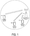
- FIG. 1 is a conceptual diagram of a radio communication system according to the present embodiment.
- the radio communication system includes terminal devices 1A to 1C and a base station device 3.
- Each of or whole of the terminal devices 1A to 1C are referred to as a terminal device 1 below.
- Carrier aggregation will be described below.
- multiple serving cells are configured for the terminal device 1.
- a technology in which the terminal device 1 communicates via the multiple serving cells is referred to as cell aggregation or carrier aggregation.
- the present invention may be applied to each of the multiple serving cells configured for the terminal device 1.
- the present invention may be applied to some of the configured multiple serving cells.
- the present invention may be applied to each of groups of the configured multiple serving cells.
- the present invention may be applied to some of the groups of the configured multiple serving cells.
- carrier aggregation multiple serving cells thus configured are also referred to as aggregated serving cells.
- Time Division Duplex (TDD) and/or Frequency Division Duplex (FDD) is applied to a radio communication system according to the present embodiment.
- TDD Time Division Duplex
- FDD Frequency Division Duplex
- serving cells to which TDD is applied and serving cells to which FDD is applied may be aggregated.
- a serving cell to which TDD is applied is also referred to as a TDD serving cell.
- the configured multiple serving cells include one primary cell and one or multiple secondary cells.
- the primary cell is a serving cell in which an initial connection establishment procedure has been performed, a serving cell in which a connection re-establishment procedure has been started, or a cell indicated as a primary cell during a handover procedure.
- RRC Radio Resource Control
- the secondary cell(s) may be configured.
- a carrier corresponding to a serving cell in the downlink is referred to as a downlink component carrier.
- a carrier corresponding to a serving cell in the uplink is referred to as an uplink component carrier.
- the downlink component carrier and the uplink component carrier are collectively referred to as a component carrier.
- the terminal device 1 can perform simultaneous transmission of multiple physical channels/multiple physical signals in multiple aggregated serving cells (component carriers).
- the terminal device 1 can perform simultaneous reception of multiple physical channels/multiple physical signals in multiple aggregated serving cells (component carriers).
- FIG. 2 is a diagram illustrating a schematic configuration of a radio frame according to the present embodiment.
- the horizontal axis is a time axis.
- T s 1/(15000 ⁇ 2048) seconds.
- Each radio frame includes 10 subframes consecutive in the time domain.
- Each subframe i includes two slots consecutive in the time domain. The two slots consecutive in the time domain are a slot of which a slot number n s within the radio frame is 2i and a slot of which the slot number n s within the radio frame is 2i+1.
- Each radio frame includes 10 subframes consecutive in the time domain.
- FIG. 3 is a diagram illustrating a schematic configuration of an uplink slot according to the present embodiment.
- the configuration of the uplink slot in one cell is illustrated.
- the horizontal axis is a time axis
- the vertical axis is a frequency axis.
- 1 is a Single Carrier-Frequency Division Multiple Access (SC-FDMA) symbol number/index
- k is a subcarrier number/index.
- SC-FDMA Single Carrier-Frequency Division Multiple Access
- the physical signal or the physical channel transmitted in each of the slots is expressed by a resource grid.
- the resource grid is defined by multiple subcarriers and multiple SC-FDMA symbols.
- Each element within the resource grid is referred to as a resource element.
- a resource element is expressed by the subcarrier number/index k and the SC-FDMA symbol number/index 1.
- the resource grid is defined for each antenna port. In the present embodiment, description will be given for one antenna port. The present embodiment may be applied to each of multiple antenna ports.
- N UL symb indicates the number of SC-FDMA symbols included in one uplink slot.
- CP Cyclic Prefix
- CP Cyclic Prefix
- CP Cyclic Prefix
- CP Cyclic Prefix
- N UL symb is 6.
- N UL RB is an uplink bandwidth configuration for the serving cell, expressed by a multiple of N RB sc .
- N RB sc is a (physical) resource block size in the frequency domain, expressed by the number of subcarriers.
- a subcarrier interval ⁇ f is 15 kHz
- N RB sc is 12 subcarriers.
- N RB sc is 180 kHz.
- a resource block is used to express mapping of a physical channel to a resource element.
- a virtual resource block and a physical resource block are defined.
- the physical channel is first mapped to the virtual resource block.
- the virtual resource block is mapped to the physical resource block.
- One physical resource block is defined by N UL symb SC-FDMA symbols consecutive in the time domain and by N RB sc subcarriers consecutive in the frequency domain. Therefore, one physical resource block is constituted of (N UL symb ⁇ N RB sc ) resource elements.
- One physical resource block corresponds to one slot in the time domain. Physical resource blocks are numbered (0, 1,..., N UL RB - 1) in order from low frequency in the frequency domain.
- a downlink slot according to the present embodiment includes multiple OFDM symbols.
- the configuration of the downlink slot according to the present embodiment is the same, except that the resource grid is defined by multiple subcarriers and multiple OFDM symbols. Therefore, a description of the configuration of the downlink slot will be omitted.
- the following uplink physical channels are used.
- the uplink physical channels are used by the physical layer to transmit information output from a higher layer.
- the PUCCH is used to transmit Uplink Control Information (UCI).
- the uplink control information includes: downlink Channel State Information (CSI); a Scheduling Request (SR) used for requesting a PUSCH (UpLink Shared CHannel (UL-SCH)) resource for initial transmission; and a Hybrid Automatic Repeat reQuest ACKnowledgement (HARQ-ACK) for downlink data (a Transport block, a Medium Access Control Protocol Data Unit (MAC PDU), a DownLink-Shared CHannel (DL-SCH), or a Physical Downlink Shared CHannel (PDSCH)).
- CSI downlink Channel State Information
- SR Scheduling Request
- HARQ-ACK Hybrid Automatic Repeat reQuest ACKnowledgement
- HARQ-ACK indicates an ACKnowledgement (ACK) or a Negative-ACKnowledgement (NACK).
- the PUSCH is used to transmit uplink data (Uplink-Shared CHannel (UL-SCH)).
- the PUSCH is used to transmit a random access message 3.
- the PUSCH may be used to transmit the HARQ-ACK and/or channel state information with the uplink data not including the random access message 3.
- the PUSCH may be used to transmit only the channel state information or to transmit only the HARQ-ACK and the channel state information.
- Quadrature Phase Shift Keying QPSK
- 16 Quadrature Amplitude Modulation QAM
- 64 QAM 64 QAM
- 256 QAM 256 QAM is applied to the PUSCH.
- the QPSK is a modulation scheme that transmits data by changing or adjusting the phase of a carrier wave.
- the QAM is a modulation scheme that transmits data by changing or adjusting the amplitude and the phase of an in-phase carrier wave and a quadrature carrier wave.
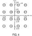
- FIG. 4 is a diagram illustrating one example of a constellation of 16 QAM symbols according to the present embodiment.
- a circle denoted by reference sign 400 is a signal point corresponding to 4 bits with a value of '0001'.
- a symbol with a modulation order of 2 indicates a QPSK symbol
- a symbol with a modulation order of 4 indicates 16 QAM
- a symbol with a modulation order of 6 indicates a 64 QAM symbol
- a symbol with a modulation order of 8 indicates a 256 QAM symbol.
- the modulation order for the PUSCH is 2
- QPSK is applied to the PUSCH.
- 16 QAM is applied to the PUSCH.
- 64 QAM is applied to the PUSCH.
- the modulation order for the PUSCH is 8, 256 QAM is applied to the PUSCH.
- the PRACH is used to transmit a random access preamble (a random access message 1).
- the PRACH is used for the initial connection establishment procedure, the handover procedure, the connection re-establishment procedure, synchronization (timing adjustment) for uplink transmission, and the request for the PUSCH (UL-SCH) resource.
- the following uplink physical signal is used in the uplink radio communication.
- the uplink physical signal is not used to transmit information output from a higher layer, but is used by the physical layer.
- the following two types of uplink reference signals are used.
- the DMRS is associated with transmission of the PUSCH or the PUCCH.
- the DMRS is time-multiplexed with the PUSCH or the PUCCH.
- the base station device 3 uses the DMRS in order to perform channel compensation of the PUSCH or the PUCCH. Transmission of both the PUSCH and the DMRS is hereinafter referred to simply as transmission of the PUSCH. Transmission of both the PUCCH and the DMRS is hereinafter referred to simply as transmission of the PUCCH.
- the SRS has no association with the transmission of the PUSCH or the PUCCH.
- the base station device 3 may use the SRS for measurement of a channel state.
- the SRS is transmitted in the last SC-FDMA symbol in the uplink subframe or in the SC-FDMA symbol in UpPTS.
- the following downlink physical channels are used for downlink radio communication from the base station device 3 to the terminal device 1.
- the downlink physical channel is used by the physical layer to transmit information output from a higher layer.
- the PBCH is used to broadcast a Master Information Block (MIB) or a Broadcast CHannel (BCH), which is shared by the terminal devices 1.
- MIB Master Information Block
- BCH Broadcast CHannel
- the PCFICH is used to transmit information indicating a region (OFDM symbols) to be used for transmission of the PDCCH.
- the PHICH is used to transmit a HARQ indicator (HARQ feedback or response information) indicating an ACKnowledgement (ACK) or a Negative ACKnowledgement (NACK) with respect to the uplink data (UpLink Shared CHannel (UL-SCH)) received by the base station device 3.
- HARQ indicator HARQ feedback or response information
- ACK ACKnowledgement
- NACK Negative ACKnowledgement
- the PDCCH and the EPDCCH are used to transmit Downlink Control Information (DCI).
- DCI Downlink Control Information
- the downlink control information is also referred to as a DCI format.
- the downlink control information includes a downlink grant and an uplink grant.
- the downlink grant is also referred to as downlink assignment or downlink allocation.
- a single downlink grant is used for scheduling of a single PDSCH within a single cell.
- the downlink grant is used for scheduling of the PDSCH within the same subframe as the subframe in which the downlink grant is transmitted.
- a single uplink grant is used for scheduling of a single PUSCH within a single serving cell.
- the uplink grant is used for scheduling of the PUSCH within the fourth or later subframe from the subframe in which the uplink grant is transmitted.
- the uplink grant transmitted in the PDCCH includes a DCI format 0.
- the transmission scheme of the PUSCH corresponding to the DCI format 0 is single antenna port.
- the terminal device 1 uses the single antenna port transmission scheme for transmitting PUSCH corresponding to the DCI format 0.
- the PUSCH, to which the single antenna port transmission scheme is applied, is used in transmission of a single codeword (single transport block).
- the uplink grant transmitted in the PDCCH includes a DCI format 4.
- the transmission scheme of the PUSCH corresponding to the DCI format 4 is closed loop spatial multiplexing.
- the terminal device 1 uses the closed loop spatial multiplexing transmission scheme for PUSCH transmission corresponding to the DCI format 4.
- the PUSCH to which the closed loop spatial multiplexing transmission scheme is applied is used in transmission of up to two codewords (up to two transport blocks).
- C-RNTI Cell-Radio Network Temporary Identifier
- SPS C-RNTI Semi Persistent Scheduling Cell-Radio Network Temporary Identifier
- the C-RNTI is used to control the PDSCH or the PUSCH in a single subframe.
- the SPS C-RNTI is used to periodically allocate a resource for the PDSCH or the PUSCH.
- the Temporary C-RNTI is used to schedule retransmission of the random access message 3 and transmission of a random access message 4.
- the PDSCH is used to transmit downlink data (DownLink Shared CHannel (DL-SCH)).
- the PDSCH is used to transmit a random access message 2 (random access response).
- the random access response includes a random access response grant.
- the random access response grant is an uplink grant transmitted on the PDSCH.
- the terminal device 1 uses the single antenna port transmission scheme for PUSCH transmission corresponding to the random access response grant and the PUSCH retransmission corresponding to the same transport block.
- the PMCH is used to transmit multicast data (Multicast CHannel (MCH)).
- MCH Multicast CHannel
- the following downlink physical signals are used in the downlink radio communication.
- the downlink physical signals are not used to transmit information output from a higher layer, but are used by the physical layer.
- the synchronization signal is used in order for the terminal device 1 to be synchronized in terms of frequency and time domains for downlink.
- the downlink reference signal is used in order for the terminal device 1 to perform the channel compensation of the downlink physical channel.
- the downlink reference signal is used in order for the terminal device 1 to calculate the downlink channel state information.
- the following seven types of downlink reference signals are used.
- the downlink physical channels and the downlink physical signals are collectively referred to as a downlink signal.
- the uplink physical channels and the uplink physical signals are collectively referred to as an uplink signal.
- the downlink physical channels and the uplink physical channels are collectively referred to as a physical channel.
- the downlink physical signals and the uplink physical signals are collectively referred to as a physical signal.
- the BCH, the MCH, the UL-SCH, and the DL-SCH are transport channels.
- a channel used in the Medium Access Control (MAC) layer is referred to as a transport channel.
- the unit of the transport channel used in the MAC layer is referred to as a Transport Block (TB) or a MAC Protocol Data Unit (PDU).
- Control of a Hybrid Automatic Repeat reQuest (HARQ) is performed for each transport block in the MAC layer.
- the transport block is a unit of data that the MAC layer delivers to the physical layer. In the physical layer, the transport block is mapped to a codeword, and coding processing is performed on a codeword-by-codeword basis.
- the base station device 3 and the terminal device 1 communicate a signal in (transmit and receive a signal to and from) a higher layer.
- a Radio Resource Control (RRC) layer the base station device 3 and the terminal device 1 may transmit and receive RRC signaling (also referred to as a Radio Resource Control message (RRC message) or Radio Resource Control information (RRC information)).
- RRC signaling also referred to as a Radio Resource Control message (RRC message) or Radio Resource Control information (RRC information)
- RRC information Radio Resource Control information
- MAC Medium Access Control
- the base station device 3 and the terminal device 1 may transmit and receive a MAC Control Element (CE).
- CE MAC Control Element
- the RRC signaling and/or MAC CE is also referred to as higher layer signaling.
- the PUSCH and the PDSCH are used to transmit the RRC signaling and the MAC CE.
- the RRC signaling transmitted in the PDSCH from the base station device 3 may be signaling common to multiple terminal devices 1 within a cell.
- the RRC signaling transmitted on the PDSCH from the base station device 3 may be signaling dedicated to a certain terminal device 1 (also referred to as dedicated signaling or UE specific signaling).
- a cell specific parameter may be transmitted using signaling common to multiple terminal devices 1 within a cell or signaling dedicated to a certain terminal device 1.
- a UE specific parameter may be transmitted using signaling dedicated to a certain terminal device 1.
- the terminal device 1 For each HARQ process, the terminal device 1 performs initial transmission or retransmission of the PUSCH, based on a New Data Indicator (NDI) included in the DCI format 0 along with the CRC parity bits scrambled by the C-RNTI and the DCI format 4 along with the CRC parity bits scrambled by the C-RNTI.
- the terminal device 1 performs the initial transmission of the PUSCH (transport block), based on the NDI being toggled.
- the terminal device 1 performs the retransmission of the PUSCH (transport block), based on the NDI not being toggled.
- the terminal device 1 stores the received value of NDI for each HARQ process.
- the NDI being toggled indicates that the stored value of NDI is different from the received value of NDI.
- the NDI not being toggled indicates that the stored value of NDI and the received value of NDI are the same.
- the random access response grant does not include the NDI.
- the terminal device 1 assumes that the NDI is toggled. Specifically, the terminal device 1 performs the initial transmission of the PUSCH (transport block), upon reception of the random access response grant.
- the terminal device 1 assumes that the NDI is not toggled. Specifically, the terminal device 1 performs the retransmission of the PUSCH (transport block, random access message 3), upon reception of the DCI format 0 along with the CRC parity bits scrambled by the Temporayr C-RNTI.
- the random access procedure may be performed in the primary cell and the secondary cell(s).
- the PRACH may be transmitted in the primary cell and the secondary cell(s).
- the terminal device 1 receives, from the base station device 3, information (RRC message) relating to the random access procedure in the primary cell.
- the information relating to the random access procedure in the primary cell may include information indicating a set of PRACH resources in the primary cell.
- the PRACH may be transmitted in the secondary cell(s).
- the terminal device 1 receives, from the base station device 3, information (RRC message) relating to the random access procedure in the secondary cell(s).
- the information relating to the random access procedure in the secondary cell(s) may include information indicating a set of PRACH resources in the secondary cell(s).
- the random access procedure includes the contention based random access procedure and a non-contention based random access procedure.
- the contention based random access procedure and the non-contention based random access procedure are supported.
- the non-contention based random access procedure is supported.
- the non-contention based random access procedure is not supported.
- the retransmission of the transport block (random access message 3) transmitted in the PUSCH corresponding to the random access response for the non-contention based random access procedure is controlled by the DCI format 0 along with the CRC parity bits scrambled by the Temporary C-RNTI.
- the retransmission of the transport block transmitted on the PUSCH corresponding to the random access response for the contention based random access procedure is controlled by the DCI format 0 along with the CRC parity bits scrambled by the C-RNTI.
- the PUSCH transmission corresponding to the DCI format 0 along with the CRC parity bits scrambled by the C-RNTI is not PUSCH transmission corresponding to the random access response grant in the non-contention based random access procedure or retransmission of the same transport.
- the PUSCH transmission corresponding to the DCI format 0 along with the CRC parity bits scrambled by the Temporary C-RNTI is retransmission of the same transport as the transport block transmitted on the PUSCH corresponding to the random access response grant in the non-contention based random access procedure.
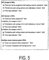
- FIG. 5 is a diagram illustrating one example of information included in the uplink grant according to the present embodiment.
- a DCI format 0 (500) includes at least (a) a 'Resource block assignment and hopping resource allocation' field, (b) a 'Modulation and coding scheme and redundancy version' field, and (c) a 'New data indicator' field.
- a DCI format 4 includes at least (d) a 'Resource block assignment' field, (e) a 'Modulation and coding scheme and redundancy version' field for transport block 1, (f) a 'New data indicator' field for transport block 1, (g) a 'Modulation and coding scheme and redundancy version' field for transport block 2, and (h) a 'New data indicator' field for transport block 2.
- the random access response grant (504) includes at least (i) a 'Fixed size resource block assignment' field and (j) a 'Truncated modulation and coding scheme' field.
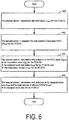
- FIG. 6 is a diagram illustrating one example of a method of acquiring scheduling information for the PUSCH according to the present embodiment.
- the scheduling information includes the total number of allocated physical resource blocks (N PRB ), a modulation order (Q m ), a redundancy version (rv idx ), and a transport block size.
- the redundancy version (rv idx ) is used for coding (rate matching) of the transport block transmitted on the PUSCH.
- the transport block size is the number of bits of the transport block.
- the terminal device 1 performs processing of FIG. 6 for each serving cell and for each PUSCH.
- the terminal device 1 determines an MCS index (I MCS ) for the PUSCH, based on (b) the 'Modulation and coding scheme and redundancy version' field, (e) the 'Modulation and coding scheme and redundancy version' field for transport block 1, (g) the 'Modulation and coding scheme and redundancy version' field for transport block 2, or (j) the 'Truncated modulation and coding scheme' field.
- I MCS MCS index
- the terminal device 1 calculates the total number of physical resource blocks (N PRB ) allocated to the PUSCH, based on (a) the 'Resource block assignment and hopping resource allocation' field, (d) the 'Resource block assignment' field, or (i) the 'Fixed size resource block assignment' field.
- the terminal device 1 determines the modulation order (Q m ) for the PUSCH, a transport block size index (I TBS ) for the PUSCH, and the redundancy version (rv idx ) for the PUSCH, by referring to the MCS index (I MCS ) for the PUSCH determined in 600.
- the terminal device 1 determines a transport block size (TBS) for the PUSCH, by referring to the total number of physical resource blocks (N PRB ) allocated to the PUSCH calculated in 602 and the MCS index (I MCS ) for the PUSCH that has been determined in 604.
- TBS transport block size
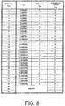
- FIG. 7 and FIG. 8 are diagrams illustrating correspondence tables of the MCS index (I MCS ), (Q' m ), the transport block size index (I TBS ), and the redundancy version (rv idx ) according to the present embodiment.
- the terminal device 1 and the base station device 3 use one of the correspondence table indicated by FIG. 7 and the correspondence table indicated by Fig. 8 .
- Q' m is used to determine the modulation order (Q m ).
- the correspondence of the MCS index (I MCS ) and the redundancy version (rv idx ) in the correspondence table of FIG. 7 is the same with the correspondence of the MCS index (I MCS ) and the redundancy version (rv idx ) in the correspondence table of FIG. 8 .
- FIG. 7 in a case that the value of the MCS index (I MCS ) is 28, (Q' m ) is 8, the transport block size index (I TBS ) is 33, and the redundancy version (rv idx ) is 0.
- FIG. 7 and FIG. 8 in a case that the value of the MCS index (I MCS ) is 29, 30, or 31, (Q' m ) and the transport block size index (I TBS ) are reserved.
- the MCS indexes (I MCS ) of 29, 30, and 31 are used for the retransmission of the PUSCH.
- the terminal device 1 uses one of the correspondence table of FIG. 7 and the correspondence table of FIG. 8 , based on some or all of the following conditions.
- the base station device 3 may transmit the RRC message including the higher layer parameter enable256QAM for the serving cell to the terminal device 1.
- the terminal device 1 may configure the higher layer parameter enable256QAM for the serving cell, based on the RRC message.
- the higher layer parameter enable256QAM indicates that 256 QAM for the PUSCH is allowed.
- the base station device 3 may transmit the RRC message including the higher layer parameter enable64QAM for the serving cell to the terminal device 1.
- the terminal device 1 may configure the higher layer parameter enable64QAM for the serving cell, based on the RRC message.
- the higher layer parameter enable64QAM indicates that 64 QAM for the PUSCH is allowed.
- the base station device 3 may cause the terminal device 1 to be always configured with the higher layer parameter enable64QAM, in a case that the terminal device 1 is configured with the higher layer parameter enable256QAM. In a case that the higher layer parameter enable256QAM is configured, the terminal device 1 may ignore or release the higher layer parameter enable64QAM.
- FIG. 9 is a diagram illustrating the correspondence of the total number of allocated physical resource blocks (N PRB ), the transport block size index (I TBS ), and the transport block size according to the present embodiment.
- the transport block size is 16, in a case that the total number of physical resource blocks (N PRB ) allocated to the PUSCH is 1 and the transport block size index (I TBS ) for the PUSCH is 0.
- FIG. 10 is a diagram illustrating a pseudo-code (1000) for determining the transport block size index (I TBS ) for the transport block in the PUSCH with respect to the MCS index (I MCS ) of 0 to 28 according to the present embodiment.
- the DCI format 4 may be included in a first DCI format.
- the DCI format 0 may be included in one of a first DCI format and a second DCI format.
- the transport block size index (I TBS ) for the PUSCH is given by using the MCS index (I MCS ) and the correspondence table indicated by FIG. 7 .
- the transport block size index (I TBS ) for the PUSCH is given by using the MCS index (I MCS ) and the correspondence table indicated by FIG. 8 .
- the transport block size index (I TBS ) for the PUSCH is given by using the MCS index (I MCS ) and the correspondence table indicated by FIG. 8 .
- the transport block size index (I TBS ) for the PUSCH is given by using the MCS index (I MCS ) and the correspondence table indicated by FIG. 8 .
- the transport block size index (I TBS ) for the PUSCH is given by using the MCS index (I MCS ) and the correspondence table indicated by FIG. 8 .
- the RNTI other than the C-RNTI may include the SPS C-RNTI and/or the Temporary C-RNTI.
- the transport block size index (I TBS ) for the PUSCH is given by using the MCS index (I MCS ) and the correspondence table indicated by FIG. 8 .
- the transport block size index (I TBS ) for the PUSCH is given by using the MCS index (I MCS ) and the correspondence table indicated by FIG. 8 .
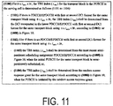
- FIG. 11 is a diagram illustrating a pseudo-code (1100) for determining the transport block size (I TBS ) for the transport block in the PUSCH with respect to the MCS index (I MCS ) of 29 to 31 according to the present embodiment.
- the TBS index (I TBS ) is determined from the downlink control information transported in the latest (last) PDCCH/EPDCCH with the first or second DCI format for the same transport block using the MCS index (I MCS ) of 0 to 28, according to (1002) or (1008) in FIG. 10 .
- the downlink control information is (b), (e), or (g) in FIG. 5 .
- the TBS index (I TBS ) is determined from the most recent semi-persistent scheduling assignment PDCCH/EPDCCH according to (1008) in FIG. 10 .
- the semi-persistent scheduling assignment PDCCH/EPDCCH is a PDCCH/EPDCCH with the first or second DCI format along with the CRC parity bits scrambled by the SPS C-RNTI.
- the TBS index (I TBS ) is determined from the random access response grant for the same transport block according to (1008) in FIG. 10 .
- FIG. 12 is a diagram illustrating a pseudo-code (1200) for determining the modulation order (Q m ) for the PUSCH with respect to the MCS index (I MCS ) of 0 to 28 according to the present embodiment.
- (1201) in FIG. 12 is the same with (1001) in FIG. 10 .
- min is a function that outputs the smallest value out of multiple values inside brackets.
- the RNTI other than the C-RNTI may include the SPS C-RNTI and/or the Temporary C-RNTI.
- (1205) in FIG. 12 is the same with (1005) in FIG. 10 .
- FIG. 13 is a diagram illustrating a pseudo-code (1300) for determining the modulation order (Q m ) for the PUSCH with respect to the MCS index (I MCS ) of 29 to 31 according to the present embodiment.
- the modulation order (Q m ) for the PUSCH is determined from the downlink control information transported in the latest (last) PDCCH/EPDCCH with the first or second DCI format for the same transport block using the MCS index (I MCS ) of 0 to 28, according to (1202), (1208), or (1210) in FIG. 12 .
- the downlink control information is (b), (e), or (g) in FIG. 5 .
- the modulation order (Q m ) for the PUSCH is determined from the most recent semi-persistent scheduling assignment PDCCH/EPDCCH according to (1208) or (1210) in FIG. 12 .
- the semi-persistent scheduling assignment PDCCH/EPDCCH is a PDCCH/EPDCCH with the first or second DCI format along with the CRC parity bits scrambled by the SPS C-RNTI.
- the modulation order (Q m ) for the PUSCH is determined from the random access response grant for the same transport block according to (1208) or (1210) in FIG. 12 .
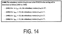
- FIG. 14 is a diagram illustrating a pseudo-code (1400) for determining the redundancy version (rv idx ) for the PUSCH according to the present embodiment.
- the redundancy version (rv idx ) is 0. (1402) In a case that the MCS index (I MCS ) is 29, the redundancy version (rv idx ) is 1. (1403) In a case that the MCS index (I MCS ) is 30, the redundancy version (rv idx ) is 2. (1404) In a case that the MCS index (I MCS ) is 31, the redundancy version (rvidx) is 3.
- the correspondence of the MCS index (I MCS ) and the redundancy version (rv idx ) in the correspondence table of FIG. 7 is the same as the correspondence of the MCS index (I MCS ) and the redundancy version (rv idx ) in the correspondence table of FIG. 8 .
- FIG. 15 is a schematic block diagram illustrating a configuration of the terminal device 1 according to the present embodiment.
- the terminal device 1 is configured to include a radio transmission and reception unit 10 and a higher layer processing unit 14.
- the radio transmission and reception unit 10 is configured to include an antenna unit 11, a radio frequency (RF) unit 12, and a baseband unit 13.
- the higher layer processing unit 14 is configured to include a medium access control layer processing unit 15 and a radio resource control layer processing unit 16.
- the radio transmission and reception unit 10 is also referred to as a transmission unit, a reception unit, or a physical layer processing unit.
- the higher layer processing unit 14 outputs uplink data (transport block) generated by a user operation or the like, to the radio transmission and reception unit 10.
- the higher layer processing unit 14 performs processing of the Medium Access Control (MAC) layer, the Packet Data Convergence Protocol (PDCP) layer, the Radio Link Control (RLC) layer, and the Radio Resource Control (RRC) layer.
- MAC Medium Access Control
- PDCP Packet Data Convergence Protocol
- RLC Radio Link Control
- RRC Radio Resource Control
- the medium access control layer processing unit 15 included in the higher layer processing unit 14 performs processing of the medium access control layer.
- the medium access control layer processing unit 15 controls transmission of the scheduling request, based on various configuration information/parameters managed by the radio resource control layer processing unit 16.
- the radio resource control layer processing unit 16 included in the higher layer processing unit 14 performs processing of the radio resource control layer.
- the radio resource control layer processing unit 16 manages various configuration information/parameters of the terminal device 1 itself.
- the radio resource control layer processing unit 16 sets the various configuration information/parameters the higher layer signaling received from the base station device 3. Specifically, the radio resource control layer processing unit 16 sets the various configuration information/parameters in accordance with information indicating the various configuration information/parameters received from the base station device 3.
- the radio transmission and reception unit 10 performs processing of the physical layer, such as modulation, demodulation, coding, and decoding.
- the radio transmission and reception unit 10 demultiplexes, demodulates, and decodes a signal received from the base station device 3, and outputs the information resulting from the decoding to the higher layer processing unit 14.
- the radio transmission and reception unit 10 modulates and codes data to generate a transmit signal, and transmits the transmit signal to the base station device 3.
- the RF unit 12 converts (down-converts) a signal received through the antenna unit 11 into a baseband signal by orthogonal demodulation and removes unnecessary frequency components.
- the RF unit 12 outputs the processed analog signal to the baseband unit.
- the baseband unit 13 converts the analog signal input from the RF unit 12 into a digital signal.
- the baseband unit 13 removes a portion corresponding to a Cyclic Prefix (CP) from the digital signal resulting from the conversion, performs Fast Fourier Transform (FFT) on the signal from which the CP has been removed, and extracts a signal in the frequency domain.
- CP Cyclic Prefix
- FFT Fast Fourier Transform
- the baseband unit 13 performs Inverse Fast Fourier transform (IFFT) on data, generates an SC-FDMA symbol, attaches a CP to the generated SC-FDMA symbol, generates a baseband digital signal, and converts the baseband digital signal into an analog signal.
- IFFT Inverse Fast Fourier transform
- the baseband unit 13 outputs the analog signal resulting from the conversion, to the RF unit 12.
- the RF unit 12 removes unnecessary frequency components from the analog signal input from the baseband unit 13 using a low-pass filter, up-converts the analog signal into a signal of a carrier frequency, and transmits the final result via the antenna unit 11. Furthermore, the RF unit 12 amplifies power. Furthermore, the RF unit 12 may include a function of controlling transmit power. The RF unit 12 is also referred to as a transmit power control unit.
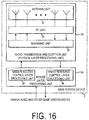
- FIG. 16 is a schematic block diagram illustrating a configuration of the base station device 3 according to the present embodiment.
- the base station device 3 is configured to include a radio transmission and reception unit 30 and a higher layer processing unit 34.
- the radio transmission and reception unit 30 is configured to include an antenna unit 31, an RF unit 32, and a baseband unit 33.
- the higher layer processing unit 34 is configured to include a medium access control layer processing unit 35 and a radio resource control layer processing unit 36.
- the radio transmission and reception unit 30 is also referred to as a transmission unit, a reception unit, or a physical layer processing unit.
- the higher layer processing unit 34 performs processing of the Medium Access Control (MAC) layer, the Packet Data Convergence Protocol (PDCP) layer, the Radio Link Control (RLC) layer, and the Radio Resource Control (RRC) layer.
- MAC Medium Access Control
- PDCP Packet Data Convergence Protocol
- RLC Radio Link Control
- RRC Radio Resource Control
- the medium access control layer processing unit 35 included in the higher layer processing unit 34 performs processing of the medium access control layer.
- the medium access control layer processing unit 35 performs processing relating to the scheduling request based on various configuration information/parameters managed by the radio resource control layer processing unit 36.
- the radio resource control layer processing unit 36 included in the higher layer processing unit 34 performs the processing of the radio resource control layer.
- the radio resource control layer processing unit 36 generates, or acquires from a higher node, downlink data (transport block) arranged on the physical downlink shared channel, system information, the RRC message, the MAC Control Element (CE), and the like, and outputs the generated or acquired data to the radio transmission and reception unit 30.
- the radio resource control layer processing unit 36 manages various configuration information/parameters for each of the terminal devices 1.
- the radio resource control layer processing unit 36 may set various configuration information/parameters for each of the terminal devices 1 via the higher layer signaling. Specifically, the radio resource control layer processing unit 36 transmits/broadcasts information indicating various configuration information/parameters.
- the functionality of the radio transmission and reception unit 30 is similar to that of the radio transmission and reception unit 10, and hence description thereof is omitted.
- Each of the units denoted by reference sign 10 to reference sign 16 included in the terminal device 1 may be configured as a circuit.
- Each of the units denoted by reference sign 30 to reference sign 36 included in the base station device 3 may be configured as a circuit.
- terminal device 1 and the base station device 3 Various aspects of the terminal device 1 and the base station device 3 according to the present embodiment will be described below.
- the terminal device and the base station device can communicate with each other efficiently using an uplink channel.
- the base station device 3 according to the present invention can be realized as an aggregation (a device group) constituted of multiple devices.
- a device group constituted of multiple devices.
- Each of devices constituting the device group may be equipped with some or all portions of each function or each functional block of the base station device 3 according to the above-described embodiment. It is only required that the device group itself include general functions or general functional blocks of the base station device 3.
- the terminal device 1 according to the above-described embodiment can also communicate with the base station device as the aggregation.
- the base station device 3 according to the above-described embodiment may be an Evolved Universal Terrestrial Radio Access Network (EUTRAN). Furthermore, the base station device 3 according to the above-described embodiment may have some or all portions of the function of a node higher than an eNodeB.
- EUTRAN Evolved Universal Terrestrial Radio Access Network
- a program running on the device according to the present invention may be a program that controls a Central Processing Unit (CPU) and the like to cause a computer to operate, in such a manner as to realize the functions according to the above-described embodiment of the present invention.
- the program or information handled by the program is temporarily read into a volatile memory such as a Random Access Memory (RAM) at the time of processing, or stored in a nonvolatile memory such as a flash memory or in a Hard Disk Drive (HDD) to be read, modified, or written by the CPU as necessary.
- RAM Random Access Memory
- HDD Hard Disk Drive
- the device according to the above-described embodiment may be partially realized by the computer.
- This configuration may be realized by recording a program for realizing such control functions on a computer-readable recording medium and causing a computer system to read the program recorded on the recording medium for execution.
- the "computer system” herein refers to a computer system built into the device, and the computer system includes an operating system and hardware components such as a peripheral device.
- the "computer-readable recording medium” may be any one of a semiconductor recording medium, an optical recording medium, a magnetic recording medium, and the like.
- the "computer-readable recording medium” may include a medium that dynamically retains the program for a short period of time, such as a communication line that is used to transmit the program over a network such as the Internet or over a communication circuit such as a telephone circuit, and a medium that retains, in that case, the program for a fixed period of time, such as a volatile memory within the computer system which functions as a server or a client.
- the program may be configured to realize some of the functions described above, and additionally may be configured to be capable of realizing the functions described above in combination with a program already recorded in the computer system.
- each functional block or various features of the devices used in the above-described embodiment may be mounted or implemented on an electrical circuit, i.e., typically an integrated circuit or multiple integrated circuits.
- An electrical circuit designed to implement the functionality described herein may include a general-purpose processor, a digital signal pressure (DSP), an application specific integrated circuit (ASIC), a field programmable gate array (FPGA) or other programmable logic devices, a discrete gate or transistor logic, a discrete hardware component, or a combination thereof.
- the general-purpose processor may be a microprocessor, but in the alternative, the processor may be any conventional processor, controller, microcontroller, or state machine.
- the general-purpose processor or each circuit described above may be configured of a digital circuit or may be configured of an analog circuit. Furthermore, if with advances in semiconductor technology, a circuit integration technology with which current integrated circuits are replaced appears, it is also possible to use an integrated circuit based on the technology.
- the present invention is not limited to above-described embodiment. According to the embodiment, one example of the devices has been described, but the present invention is not limited to this, and can be applied to a fixed-type or a stationary-type electronic apparatus installed indoors or outdoors, for example, a terminal device or a communication device, such as an audio-video (AV) apparatus, a kitchen apparatus, a cleaning or washing machine, an air-conditioning apparatus, office equipment, a vending machine, and other household apparatuses.
- AV audio-video
Landscapes
- Engineering & Computer Science (AREA)
- Signal Processing (AREA)
- Computer Networks & Wireless Communication (AREA)
- Quality & Reliability (AREA)
- Mobile Radio Communication Systems (AREA)
Claims (6)
- Endgerätvorrichtung (1), umfassend:eine Empfangseinheit (10), die konfiguriert ist zumEmpfangen einer Planung bzw. Terminierung eines Physical Uplink Shared Channel, PUSCH, undEmpfangen eines Parameters höherer Ebene bzw. Schicht, der angibt, dass 256 QAM zulässig ist; undeine Übertragungseinheit (10), die konfiguriert ist zum
Übertragen des PUSCH,wobei in einem Fall, in dem der Parameter höherer Schicht konfiguriert ist und die Planung des PUSCH in DCI auf einem Physical Downlink Control Channel, PDCCH, enthalten ist, wobei die DCI einen ersten Modulations- und Co-dierungsschema,MCS,-Index enthalten, eine Modulationsreihenfolge Qm für den PUSCH gegeben ist basierend auf einem ersten Index Q'm in einer ersten Tabelle, wobei der erste Index Q'm dem ersten MCS-Index basierend auf der ersten Tabelle entspricht,in einem Fall, in dem der Parameter der höheren Schicht nicht konfiguriert ist und die Planung des PUSCH in den DCI auf dem PDCCH enthalten ist, die Modulationsreihenfolge Qm für den PUSCH basierend auf einem zweiten Index Q'm in einer zweiten Tabelle gegeben ist, wobei der zweite Index Q'm dem ersten MCS-Index basierend auf der zweiten Tabelle entspricht, undin einem Fall, dass die Planung des PUSCH in einer Uplink-Gewährung enthalten ist, die in einer Direktzugriffsantwort enthalten ist, wobei die Uplink-Gewährung einen zweiten MCS-Index enthält, die Modulationsreihenfolge Qm für den PUSCH basierend auf einem dritten Index Q'm in der zweiten Tabelle gegeben ist, wobei der dritte Index Q'm dem zweiten MCS-Index basierend auf der zweiten Tabelle entspricht. - Endgerätvorrichtung (1) nach Anspruch 1, wobei der erste MCS-Index und der zweite MCS-Index kleiner als 29 sind.
- Basisstationsvorrichtung (3), umfassend:eine Übertragungseinheit (30), die konfiguriert ist zumÜbertragen einer Planung bzw. Terminierung eines Physical Uplink Shared Channel, PUSCH, undÜbertragen eines Parameters höherer Ebene bzw. Schicht, der angibt, dass 256 QAM zulässig ist; undeine Empfangseinheit (30), die konfiguriert ist zum
Empfangen des PUSCH,wobei in einem Fall, in dem der Parameter höherer Schicht konfiguriert ist und die Planung des PUSCH in DCI auf einem Physical Downlink Control Channel, PDCCH, enthalten ist, wobei die DCI einen ersten Modulations- und Codierungsschema,MCS,-Index enthalten, eine Modulationsreihenfolge Qm für den PUSCH gegeben ist basierend auf einem ersten Index Q'm in einer ersten Tabelle, wobei der erste Index Q'm dem ersten MCS-Index basierend auf der ersten Tabelle entspricht,in einem Fall, in dem der Parameter der höheren Schicht nicht konfiguriert ist und die Planung des PUSCH in den DCI auf dem PDCCH enthalten ist, die Modulationsreihenfolge Qm für den PUSCH basierend auf einem zweiten Index Q'm in einer zweiten Tabelle gegeben ist, wobei der zweite Index Q'm dem ersten MCS-Index basierend auf der zweiten Tabelle entspricht, undin einem Fall, dass die Planung des PUSCH in einer Uplink-Gewährung enthalten ist, die in einer Direktzugriffsantwort enthalten ist, wobei die Uplink-Gewährung einen zweiten MCS-Index enthält, die Modulationsreihenfolge Qm für den PUSCH basierend auf einem dritten Index Q'm in der zweiten Tabelle gegeben ist, wobei der dritte Index Q'm dem zweiten MCS-Index basierend auf der zweiten Tabelle entspricht. - Basisstationsvorrichtung (3) nach Anspruch 3, wobei der erste MCS-Index und der zweite MCS-Index kleiner als 29 sind.
- Kommunikationsverfahren, das von einer Endgerätvorrichtung (1) verwendet wird, wobei das Kommunikationsverfahren umfasst:Empfangen einer Planung bzw. Terminierung eines Physical Uplink Shared Channel, PUSCH, undEmpfangen eines Parameters höherer Ebene bzw. Schicht, der angibt, dass 256 QAM zulässig ist; undÜbertragen des PUSCH,wobei in einem Fall, in dem der Parameter höherer Schicht konfiguriert ist und die Planung des PUSCH in DCI auf einem Physical Downlink Control Channel, PDCCH, enthalten ist, wobei die DCI einen ersten Modulations- und Codierungsschema,MCS,-Index enthalten, eine Modulationsreihenfolge Qm für den PUSCH gegeben ist basierend auf einem ersten Index Q'm in einer ersten Tabelle, wobei der erste Index Q'm dem ersten MCS-Index basierend auf der ersten Tabelle entspricht,in einem Fall, in dem der Parameter der höheren Schicht nicht konfiguriert ist und die Planung des PUSCH in den DCI auf dem PDCCH enthalten ist, die Modulationsreihenfolge Qm für den PUSCH basierend auf einem zweiten Index Q'm in einer zweiten Tabelle gegeben ist, wobei der zweite Index Q'm dem ersten MCS-Index basierend auf der zweiten Tabelle entspricht, undin einem Fall, dass die Planung des PUSCH in einer Uplink-Gewährung enthalten ist, die in einer Direktzugriffsantwort enthalten ist, wobei die Uplink-Gewährung einen zweiten MCS-Index enthält, die Modulationsreihenfolge Qm für den PUSCH basierend auf einem dritten Index Q'm in der zweiten Tabelle gegeben ist, wobei der dritte Index Q'm dem zweiten MCS-Index basierend auf der zweiten Tabelle entspricht.
- Kommunikationsverfahren, das von einer Basisstationsvorrichtung (3) verwendet wird, wobei das Kommunikationsverfahren umfasst:Übertragen einer Planung bzw. Terminierung eines Physical Uplink Shared Channel, PUSCH, undÜbertragen eines Parameters höherer Ebene bzw. Schicht, der angibt, dass 256 QAM zulässig ist; undEmpfangen des PUSCH,wobei in einem Fall, in dem der Parameter höherer Schicht konfiguriert ist und die Planung des PUSCH in DCI auf einem Physical Downlink Control Channel, PDCCH, enthalten ist, wobei die DCI einen ersten Modulations- und Codierungsschema,MCS,-Index enthalten, eine Modulationsreihenfolge Qm für den PUSCH gegeben ist basierend auf einem ersten Index Q'm in einer ersten Tabelle, wobei der erste Index Q'm dem ersten MCS-Index basierend auf der ersten Tabelle entspricht,in einem Fall, in dem der Parameter der höheren Schicht nicht konfiguriert ist und die Planung des PUSCH in den DCI auf dem PDCCH enthalten ist, die Modulationsreihenfolge Qm für den PUSCH basierend auf einem zweiten Index Q'm in einer zweiten Tabelle gegeben ist, wobei der zweite Index Q'm dem ersten MCS-Index basierend auf der zweiten Tabelle entspricht, undin einem Fall, dass die Planung des PUSCH in einer Uplink-Gewährung enthalten ist, die in einer Direktzugriffsantwort enthalten ist, wobei die Uplink-Gewährung einen zweiten MCS-Index enthält, die Modulationsreihenfolge Qm für den PUSCH basierend auf einem dritten Index Q'm in der zweiten Tabelle gegeben ist, wobei der dritte Index Q'm dem zweiten MCS-Index basierend auf der zweiten Tabelle entspricht.
Applications Claiming Priority (2)
| Application Number | Priority Date | Filing Date | Title |
|---|---|---|---|
| JP2015212700 | 2015-10-29 | ||
| PCT/JP2016/073822 WO2017073135A1 (ja) | 2015-10-29 | 2016-08-15 | 端末装置、基地局装置、通信方法、および、集積回路 |
Publications (3)
| Publication Number | Publication Date |
|---|---|
| EP3370458A1 EP3370458A1 (de) | 2018-09-05 |
| EP3370458A4 EP3370458A4 (de) | 2019-05-08 |
| EP3370458B1 true EP3370458B1 (de) | 2020-10-28 |
Family
ID=58630133
Family Applications (1)
| Application Number | Title | Priority Date | Filing Date |
|---|---|---|---|
| EP16859372.1A Active EP3370458B1 (de) | 2015-10-29 | 2016-08-15 | Unterstützung der 256-qam-modulation für pusch |
Country Status (6)
| Country | Link |
|---|---|
| US (1) | US11044638B2 (de) |
| EP (1) | EP3370458B1 (de) |
| JP (1) | JP6751099B2 (de) |
| CN (1) | CN108353323B (de) |
| NZ (1) | NZ741942A (de) |
| WO (1) | WO2017073135A1 (de) |
Families Citing this family (17)
| Publication number | Priority date | Publication date | Assignee | Title |
|---|---|---|---|---|
| CN111279771B (zh) * | 2017-09-05 | 2023-07-25 | 上海诺基亚贝尔股份有限公司 | 用于通信的方法和装置 |
| WO2019073464A1 (en) * | 2017-10-13 | 2019-04-18 | Telefonaktiebolaget Lm Ericsson (Publ) | DETERMINATION OF TRANSPORT BLOCK SIZE FOR NEW RADIO |
| US10944501B2 (en) * | 2017-12-15 | 2021-03-09 | Mediatek Singapore Pte. Ltd. | Method and apparatus for determining modulation and coding scheme table in mobile communications |
| WO2019158686A1 (en) | 2018-02-16 | 2019-08-22 | Telefonaktiebolaget Lm Ericsson (Publ) | Resource block assignment for msg3 transmission |
| CN112586044B (zh) | 2018-06-21 | 2023-08-01 | 上海诺基亚贝尔股份有限公司 | 随机接入过程中的无争用随机接入的传输块大小 |
| US10999861B2 (en) * | 2018-07-13 | 2021-05-04 | Qualcomm Incorporated | Rate matching and semi persistent scheduling configuration in wireless communications |
| AU2019314850A1 (en) * | 2018-08-01 | 2021-02-25 | Guangdong Oppo Mobile Telecommunications Corp., Ltd. | Random access method and device, and computer storage medium |
| CN113892281B (zh) * | 2019-03-26 | 2024-04-02 | 苹果公司 | 在处于ce的ue的连接模式下的etws/cmas的通知和获取 |
| WO2021029437A1 (en) * | 2019-08-09 | 2021-02-18 | Sharp Kabushiki Kaisha | Terminal devices, base station devices, and communication methods |
| EP4017164A1 (de) * | 2019-08-15 | 2022-06-22 | Ntt Docomo, Inc. | Endgerät und drahtloskommunikationsverfahren |
| EP4054287A4 (de) * | 2019-11-01 | 2023-07-12 | Ntt Docomo, Inc. | Endgerät und kommunikationsverfahren |
| CN114616783B (zh) * | 2019-11-07 | 2024-12-10 | 夏普株式会社 | 用于物理上行链路共享信道的解调参考信号的可配置下行链路控制信息的用户装备、基站和方法 |
| US12212409B2 (en) | 2020-02-11 | 2025-01-28 | Beijing Xiaomi Mobile Software Co., Ltd. | Data transmission method, data transmission apparatus and storage medium |
| US12200705B2 (en) * | 2021-01-06 | 2025-01-14 | Qualcomm Incorporated | Latency reduction and coverage enhancement for extended reality |
| US12382441B2 (en) * | 2021-12-17 | 2025-08-05 | Samsung Electronics Co., Ltd. | Uplink transmission in full-duplex systems |
| CN118140440A (zh) * | 2022-01-10 | 2024-06-04 | Oppo广东移动通信有限公司 | 无线通信的方法、终端设备和网络设备 |
| US20240039655A1 (en) * | 2022-07-29 | 2024-02-01 | Samsung Electronics Co., Ltd. | Method and apparatus for downlink and uplink transmission in full-duplex systems |
Family Cites Families (14)
| Publication number | Priority date | Publication date | Assignee | Title |
|---|---|---|---|---|
| WO2011112018A2 (ko) * | 2010-03-10 | 2011-09-15 | 엘지전자 주식회사 | 캐리어 병합 시스템에서 제어 정보를 시그널링 하는 방법 및 이를 위한 장치 |
| KR101790523B1 (ko) * | 2010-04-22 | 2017-10-26 | 엘지전자 주식회사 | 무선 통신 시스템에서 제어 정보의 전송 방법 및 장치 |
| WO2013069984A1 (ko) * | 2011-11-08 | 2013-05-16 | 엘지전자 주식회사 | 데이터 수신 방법 및 무선기기 |
| CN103220795A (zh) * | 2012-01-21 | 2013-07-24 | 中兴通讯股份有限公司 | 下行控制信息的发送方法和基站 |
| US9414409B2 (en) * | 2012-02-06 | 2016-08-09 | Samsung Electronics Co., Ltd. | Method and apparatus for transmitting/receiving data on multiple carriers in mobile communication system |
| EP2640153B1 (de) * | 2012-03-12 | 2016-04-13 | HTC Corporation | Verfahren und Vorrichtung zur Durchführung von direkter Kommunikation in einem drahtlosen Kommunikationssystem |
| JP5314779B2 (ja) * | 2012-03-14 | 2013-10-16 | シャープ株式会社 | 移動局装置、基地局装置、通信方法、集積回路および無線通信システム |
| US20130286961A1 (en) * | 2012-04-10 | 2013-10-31 | Qualcomm Incorporated | Systems and methods for wireless communication of long data units |
| US20150215068A1 (en) * | 2014-01-29 | 2015-07-30 | Htc Corporation | Method of Selecting Modulation and Transport Block Size Index Table |
| US9444655B2 (en) * | 2014-03-25 | 2016-09-13 | Intel IP Corporation | Apparatus, method and system of scrambling a wireless transmission |
| EP3211954B1 (de) * | 2014-10-21 | 2021-08-04 | LG Electronics Inc. | Verfahren zum senden/empfangen eines d2d-signals in einem drahtloskommunikationssystem und vorrichtung dafür |
| JP6867410B2 (ja) * | 2016-05-13 | 2021-04-28 | 華為技術有限公司Huawei Technologies Co.,Ltd. | アップリンク制御情報を伝送するための方法および装置 |
| US10568128B2 (en) * | 2017-06-14 | 2020-02-18 | Qualcomm Incorporated | Techniques and apparatuses for scheduling request acknowledgement |
| US11516834B2 (en) * | 2017-11-13 | 2022-11-29 | Qualcomm Incorporated | Uplink control information transmission |
-
2016
- 2016-08-15 EP EP16859372.1A patent/EP3370458B1/de active Active
- 2016-08-15 NZ NZ741942A patent/NZ741942A/en unknown
- 2016-08-15 CN CN201680063248.XA patent/CN108353323B/zh active Active
- 2016-08-15 JP JP2017547647A patent/JP6751099B2/ja active Active
- 2016-08-15 WO PCT/JP2016/073822 patent/WO2017073135A1/ja not_active Ceased
- 2016-08-15 US US15/770,723 patent/US11044638B2/en active Active
Non-Patent Citations (1)
| Title |
|---|
| None * |
Also Published As
| Publication number | Publication date |
|---|---|
| US11044638B2 (en) | 2021-06-22 |
| JP6751099B2 (ja) | 2020-09-02 |
| WO2017073135A1 (ja) | 2017-05-04 |
| EP3370458A4 (de) | 2019-05-08 |
| US20190075492A1 (en) | 2019-03-07 |
| JPWO2017073135A1 (ja) | 2018-08-16 |
| CN108353323A (zh) | 2018-07-31 |
| EP3370458A1 (de) | 2018-09-05 |
| NZ741942A (en) | 2023-10-27 |
| CN108353323B (zh) | 2022-09-27 |
Similar Documents
| Publication | Publication Date | Title |
|---|---|---|
| EP3370458B1 (de) | Unterstützung der 256-qam-modulation für pusch | |
| US10763946B2 (en) | Terminal device, base station device, communication method, and integrated circuit | |
| US20200045742A1 (en) | Terminal apparatus, base station apparatus, communication method, and integrated circuit | |
| US20190373642A1 (en) | Terminal apparatus, base station apparatus, communication method, and integrated circuit | |
| CN107852712B (zh) | 终端装置、基站装置、集成电路以及通信方法 | |
| EP3099113B1 (de) | Benutzervorrichtung, basisstationsvorrichtung, integrierte schaltung und kommunikationsverfahren | |
| RU2741320C2 (ru) | Терминальное устройство, устройство базовой станции, способ связи и интегральная схема | |
| EP4203571A1 (de) | Endgerätevorrichtung, basisstationsvorrichtung, kommunikationsverfahren und integrierte schaltung | |
| US10674478B2 (en) | Terminal device, communication method, and integrated circuit | |
| CN105075374B (zh) | 终端装置、基站装置、集成电路以及无线通信方法 | |
| US20180048429A1 (en) | Terminal device, base station device, integrated circuit, and communication method | |
| US10299308B2 (en) | Terminal device, communication method, and integrated circuit | |
| WO2016125580A1 (ja) | 端末装置、基地局装置、集積回路、および、通信方法 | |
| EP3681212B1 (de) | Endgerät und kommunikationsverfahren | |
| WO2017043255A1 (ja) | 端末装置、基地局装置、通信方法および集積回路 | |
| WO2017169159A1 (ja) | 端末装置、基地局装置、通信方法、および、集積回路 | |
| WO2016125584A1 (ja) | 端末装置、基地局装置、集積回路、および、通信方法 | |
| WO2017043257A1 (ja) | 端末装置、基地局装置、通信方法および集積回路 | |
| JP2020074500A (ja) | 端末装置、基地局装置、通信方法、および、集積回路 |
Legal Events
| Date | Code | Title | Description |
|---|---|---|---|
| STAA | Information on the status of an ep patent application or granted ep patent |
Free format text: STATUS: THE INTERNATIONAL PUBLICATION HAS BEEN MADE |
|
| PUAI | Public reference made under article 153(3) epc to a published international application that has entered the european phase |
Free format text: ORIGINAL CODE: 0009012 |
|
| STAA | Information on the status of an ep patent application or granted ep patent |
Free format text: STATUS: REQUEST FOR EXAMINATION WAS MADE |
|
| 17P | Request for examination filed |
Effective date: 20180426 |
|
| AK | Designated contracting states |
Kind code of ref document: A1 Designated state(s): AL AT BE BG CH CY CZ DE DK EE ES FI FR GB GR HR HU IE IS IT LI LT LU LV MC MK MT NL NO PL PT RO RS SE SI SK SM TR |
|
| AX | Request for extension of the european patent |
Extension state: BA ME |
|
| DAV | Request for validation of the european patent (deleted) | ||
| DAX | Request for extension of the european patent (deleted) | ||
| A4 | Supplementary search report drawn up and despatched |
Effective date: 20190405 |
|
| RIC1 | Information provided on ipc code assigned before grant |
Ipc: H04L 5/00 20060101AFI20190401BHEP Ipc: H04W 72/04 20090101ALN20190401BHEP |
|
| REG | Reference to a national code |
Ref country code: DE Ref legal event code: R079 Ref document number: 602016046885 Country of ref document: DE Free format text: PREVIOUS MAIN CLASS: H04W0028180000 Ipc: H04L0005000000 |
|
| GRAP | Despatch of communication of intention to grant a patent |
Free format text: ORIGINAL CODE: EPIDOSNIGR1 |
|
| STAA | Information on the status of an ep patent application or granted ep patent |
Free format text: STATUS: GRANT OF PATENT IS INTENDED |
|
| RIC1 | Information provided on ipc code assigned before grant |
Ipc: H04L 1/18 20060101ALN20200415BHEP Ipc: H04W 72/04 20090101ALN20200415BHEP Ipc: H04L 1/16 20060101ALN20200415BHEP Ipc: H04L 1/00 20060101ALI20200415BHEP Ipc: H04L 5/00 20060101AFI20200415BHEP |
|
| INTG | Intention to grant announced |
Effective date: 20200520 |
|
| GRAS | Grant fee paid |
Free format text: ORIGINAL CODE: EPIDOSNIGR3 |
|
| GRAA | (expected) grant |
Free format text: ORIGINAL CODE: 0009210 |
|
| STAA | Information on the status of an ep patent application or granted ep patent |
Free format text: STATUS: THE PATENT HAS BEEN GRANTED |
|
| AK | Designated contracting states |
Kind code of ref document: B1 Designated state(s): AL AT BE BG CH CY CZ DE DK EE ES FI FR GB GR HR HU IE IS IT LI LT LU LV MC MK MT NL NO PL PT RO RS SE SI SK SM TR |
|
| REG | Reference to a national code |
Ref country code: GB Ref legal event code: FG4D |
|
| REG | Reference to a national code |
Ref country code: CH Ref legal event code: EP |
|
| REG | Reference to a national code |
Ref country code: AT Ref legal event code: REF Ref document number: 1329327 Country of ref document: AT Kind code of ref document: T Effective date: 20201115 |
|
| REG | Reference to a national code |
Ref country code: DE Ref legal event code: R096 Ref document number: 602016046885 Country of ref document: DE |
|
| REG | Reference to a national code |
Ref country code: IE Ref legal event code: FG4D |
|
| REG | Reference to a national code |
Ref country code: AT Ref legal event code: MK05 Ref document number: 1329327 Country of ref document: AT Kind code of ref document: T Effective date: 20201028 |
|
| REG | Reference to a national code |
Ref country code: NL Ref legal event code: MP Effective date: 20201028 |
|
| PG25 | Lapsed in a contracting state [announced via postgrant information from national office to epo] |
Ref country code: NO Free format text: LAPSE BECAUSE OF FAILURE TO SUBMIT A TRANSLATION OF THE DESCRIPTION OR TO PAY THE FEE WITHIN THE PRESCRIBED TIME-LIMIT Effective date: 20210128 Ref country code: PT Free format text: LAPSE BECAUSE OF FAILURE TO SUBMIT A TRANSLATION OF THE DESCRIPTION OR TO PAY THE FEE WITHIN THE PRESCRIBED TIME-LIMIT Effective date: 20210301 Ref country code: RS Free format text: LAPSE BECAUSE OF FAILURE TO SUBMIT A TRANSLATION OF THE DESCRIPTION OR TO PAY THE FEE WITHIN THE PRESCRIBED TIME-LIMIT Effective date: 20201028 Ref country code: FI Free format text: LAPSE BECAUSE OF FAILURE TO SUBMIT A TRANSLATION OF THE DESCRIPTION OR TO PAY THE FEE WITHIN THE PRESCRIBED TIME-LIMIT Effective date: 20201028 Ref country code: GR Free format text: LAPSE BECAUSE OF FAILURE TO SUBMIT A TRANSLATION OF THE DESCRIPTION OR TO PAY THE FEE WITHIN THE PRESCRIBED TIME-LIMIT Effective date: 20210129 |
|
| REG | Reference to a national code |
Ref country code: LT Ref legal event code: MG4D |
|
| PG25 | Lapsed in a contracting state [announced via postgrant information from national office to epo] |
Ref country code: SE Free format text: LAPSE BECAUSE OF FAILURE TO SUBMIT A TRANSLATION OF THE DESCRIPTION OR TO PAY THE FEE WITHIN THE PRESCRIBED TIME-LIMIT Effective date: 20201028 Ref country code: BG Free format text: LAPSE BECAUSE OF FAILURE TO SUBMIT A TRANSLATION OF THE DESCRIPTION OR TO PAY THE FEE WITHIN THE PRESCRIBED TIME-LIMIT Effective date: 20210128 Ref country code: PL Free format text: LAPSE BECAUSE OF FAILURE TO SUBMIT A TRANSLATION OF THE DESCRIPTION OR TO PAY THE FEE WITHIN THE PRESCRIBED TIME-LIMIT Effective date: 20201028 Ref country code: IS Free format text: LAPSE BECAUSE OF FAILURE TO SUBMIT A TRANSLATION OF THE DESCRIPTION OR TO PAY THE FEE WITHIN THE PRESCRIBED TIME-LIMIT Effective date: 20210228 Ref country code: LV Free format text: LAPSE BECAUSE OF FAILURE TO SUBMIT A TRANSLATION OF THE DESCRIPTION OR TO PAY THE FEE WITHIN THE PRESCRIBED TIME-LIMIT Effective date: 20201028 Ref country code: AT Free format text: LAPSE BECAUSE OF FAILURE TO SUBMIT A TRANSLATION OF THE DESCRIPTION OR TO PAY THE FEE WITHIN THE PRESCRIBED TIME-LIMIT Effective date: 20201028 Ref country code: ES Free format text: LAPSE BECAUSE OF FAILURE TO SUBMIT A TRANSLATION OF THE DESCRIPTION OR TO PAY THE FEE WITHIN THE PRESCRIBED TIME-LIMIT Effective date: 20201028 |
|
| PG25 | Lapsed in a contracting state [announced via postgrant information from national office to epo] |
Ref country code: HR Free format text: LAPSE BECAUSE OF FAILURE TO SUBMIT A TRANSLATION OF THE DESCRIPTION OR TO PAY THE FEE WITHIN THE PRESCRIBED TIME-LIMIT Effective date: 20201028 Ref country code: NL Free format text: LAPSE BECAUSE OF FAILURE TO SUBMIT A TRANSLATION OF THE DESCRIPTION OR TO PAY THE FEE WITHIN THE PRESCRIBED TIME-LIMIT Effective date: 20201028 |
|
| REG | Reference to a national code |
Ref country code: DE Ref legal event code: R097 Ref document number: 602016046885 Country of ref document: DE |
|
| PG25 | Lapsed in a contracting state [announced via postgrant information from national office to epo] |
Ref country code: LT Free format text: LAPSE BECAUSE OF FAILURE TO SUBMIT A TRANSLATION OF THE DESCRIPTION OR TO PAY THE FEE WITHIN THE PRESCRIBED TIME-LIMIT Effective date: 20201028 Ref country code: SM Free format text: LAPSE BECAUSE OF FAILURE TO SUBMIT A TRANSLATION OF THE DESCRIPTION OR TO PAY THE FEE WITHIN THE PRESCRIBED TIME-LIMIT Effective date: 20201028 Ref country code: CZ Free format text: LAPSE BECAUSE OF FAILURE TO SUBMIT A TRANSLATION OF THE DESCRIPTION OR TO PAY THE FEE WITHIN THE PRESCRIBED TIME-LIMIT Effective date: 20201028 Ref country code: EE Free format text: LAPSE BECAUSE OF FAILURE TO SUBMIT A TRANSLATION OF THE DESCRIPTION OR TO PAY THE FEE WITHIN THE PRESCRIBED TIME-LIMIT Effective date: 20201028 Ref country code: RO Free format text: LAPSE BECAUSE OF FAILURE TO SUBMIT A TRANSLATION OF THE DESCRIPTION OR TO PAY THE FEE WITHIN THE PRESCRIBED TIME-LIMIT Effective date: 20201028 Ref country code: SK Free format text: LAPSE BECAUSE OF FAILURE TO SUBMIT A TRANSLATION OF THE DESCRIPTION OR TO PAY THE FEE WITHIN THE PRESCRIBED TIME-LIMIT Effective date: 20201028 |
|
| PG25 | Lapsed in a contracting state [announced via postgrant information from national office to epo] |
Ref country code: DK Free format text: LAPSE BECAUSE OF FAILURE TO SUBMIT A TRANSLATION OF THE DESCRIPTION OR TO PAY THE FEE WITHIN THE PRESCRIBED TIME-LIMIT Effective date: 20201028 |
|
| PLBE | No opposition filed within time limit |
Free format text: ORIGINAL CODE: 0009261 |
|
| STAA | Information on the status of an ep patent application or granted ep patent |
Free format text: STATUS: NO OPPOSITION FILED WITHIN TIME LIMIT |
|
| 26N | No opposition filed |
Effective date: 20210729 |
|
| PG25 | Lapsed in a contracting state [announced via postgrant information from national office to epo] |
Ref country code: IT Free format text: LAPSE BECAUSE OF FAILURE TO SUBMIT A TRANSLATION OF THE DESCRIPTION OR TO PAY THE FEE WITHIN THE PRESCRIBED TIME-LIMIT Effective date: 20201028 Ref country code: AL Free format text: LAPSE BECAUSE OF FAILURE TO SUBMIT A TRANSLATION OF THE DESCRIPTION OR TO PAY THE FEE WITHIN THE PRESCRIBED TIME-LIMIT Effective date: 20201028 |
|
| PG25 | Lapsed in a contracting state [announced via postgrant information from national office to epo] |
Ref country code: SI Free format text: LAPSE BECAUSE OF FAILURE TO SUBMIT A TRANSLATION OF THE DESCRIPTION OR TO PAY THE FEE WITHIN THE PRESCRIBED TIME-LIMIT Effective date: 20201028 |
|
| REG | Reference to a national code |
Ref country code: CH Ref legal event code: PL |
|
| PG25 | Lapsed in a contracting state [announced via postgrant information from national office to epo] |
Ref country code: MC Free format text: LAPSE BECAUSE OF FAILURE TO SUBMIT A TRANSLATION OF THE DESCRIPTION OR TO PAY THE FEE WITHIN THE PRESCRIBED TIME-LIMIT Effective date: 20201028 |
|
| REG | Reference to a national code |
Ref country code: BE Ref legal event code: MM Effective date: 20210831 |
|
| PG25 | Lapsed in a contracting state [announced via postgrant information from national office to epo] |
Ref country code: LI Free format text: LAPSE BECAUSE OF NON-PAYMENT OF DUE FEES Effective date: 20210831 Ref country code: CH Free format text: LAPSE BECAUSE OF NON-PAYMENT OF DUE FEES Effective date: 20210831 |
|
| PG25 | Lapsed in a contracting state [announced via postgrant information from national office to epo] |
Ref country code: IS Free format text: LAPSE BECAUSE OF FAILURE TO SUBMIT A TRANSLATION OF THE DESCRIPTION OR TO PAY THE FEE WITHIN THE PRESCRIBED TIME-LIMIT Effective date: 20210228 Ref country code: LU Free format text: LAPSE BECAUSE OF NON-PAYMENT OF DUE FEES Effective date: 20210815 |
|
| PG25 | Lapsed in a contracting state [announced via postgrant information from national office to epo] |
Ref country code: IE Free format text: LAPSE BECAUSE OF NON-PAYMENT OF DUE FEES Effective date: 20210815 Ref country code: BE Free format text: LAPSE BECAUSE OF NON-PAYMENT OF DUE FEES Effective date: 20210831 |
|
| PG25 | Lapsed in a contracting state [announced via postgrant information from national office to epo] |
Ref country code: CY Free format text: LAPSE BECAUSE OF FAILURE TO SUBMIT A TRANSLATION OF THE DESCRIPTION OR TO PAY THE FEE WITHIN THE PRESCRIBED TIME-LIMIT Effective date: 20201028 |
|
| PG25 | Lapsed in a contracting state [announced via postgrant information from national office to epo] |
Ref country code: HU Free format text: LAPSE BECAUSE OF FAILURE TO SUBMIT A TRANSLATION OF THE DESCRIPTION OR TO PAY THE FEE WITHIN THE PRESCRIBED TIME-LIMIT; INVALID AB INITIO Effective date: 20160815 |
|
| PG25 | Lapsed in a contracting state [announced via postgrant information from national office to epo] |
Ref country code: MK Free format text: LAPSE BECAUSE OF FAILURE TO SUBMIT A TRANSLATION OF THE DESCRIPTION OR TO PAY THE FEE WITHIN THE PRESCRIBED TIME-LIMIT Effective date: 20201028 |
|
| PG25 | Lapsed in a contracting state [announced via postgrant information from national office to epo] |
Ref country code: TR Free format text: LAPSE BECAUSE OF FAILURE TO SUBMIT A TRANSLATION OF THE DESCRIPTION OR TO PAY THE FEE WITHIN THE PRESCRIBED TIME-LIMIT Effective date: 20201028 |
|
| PG25 | Lapsed in a contracting state [announced via postgrant information from national office to epo] |
Ref country code: MT Free format text: LAPSE BECAUSE OF FAILURE TO SUBMIT A TRANSLATION OF THE DESCRIPTION OR TO PAY THE FEE WITHIN THE PRESCRIBED TIME-LIMIT Effective date: 20201028 |
|
| PGFP | Annual fee paid to national office [announced via postgrant information from national office to epo] |
Ref country code: DE Payment date: 20250820 Year of fee payment: 10 |
|
| PGFP | Annual fee paid to national office [announced via postgrant information from national office to epo] |
Ref country code: GB Payment date: 20250821 Year of fee payment: 10 |
|
| PGFP | Annual fee paid to national office [announced via postgrant information from national office to epo] |
Ref country code: FR Payment date: 20250828 Year of fee payment: 10 |