EP3370271A1 - Piezoelectric composition and piezoelectric device - Google Patents
Piezoelectric composition and piezoelectric device Download PDFInfo
- Publication number
- EP3370271A1 EP3370271A1 EP18158981.3A EP18158981A EP3370271A1 EP 3370271 A1 EP3370271 A1 EP 3370271A1 EP 18158981 A EP18158981 A EP 18158981A EP 3370271 A1 EP3370271 A1 EP 3370271A1
- Authority
- EP
- European Patent Office
- Prior art keywords
- piezoelectric
- piezoelectric composition
- composition
- chemical formula
- specific resistance
- Prior art date
- Legal status (The legal status is an assumption and is not a legal conclusion. Google has not performed a legal analysis and makes no representation as to the accuracy of the status listed.)
- Granted
Links
Images


Classifications
-
- H—ELECTRICITY
- H10—SEMICONDUCTOR DEVICES; ELECTRIC SOLID-STATE DEVICES NOT OTHERWISE PROVIDED FOR
- H10N—ELECTRIC SOLID-STATE DEVICES NOT OTHERWISE PROVIDED FOR
- H10N30/00—Piezoelectric or electrostrictive devices
- H10N30/80—Constructional details
- H10N30/85—Piezoelectric or electrostrictive active materials
- H10N30/853—Ceramic compositions
-
- C—CHEMISTRY; METALLURGY
- C01—INORGANIC CHEMISTRY
- C01G—COMPOUNDS CONTAINING METALS NOT COVERED BY SUBCLASSES C01D OR C01F
- C01G49/00—Compounds of iron
- C01G49/009—Compounds containing iron, with or without oxygen or hydrogen, and containing two or more other elements
-
- C—CHEMISTRY; METALLURGY
- C04—CEMENTS; CONCRETE; ARTIFICIAL STONE; CERAMICS; REFRACTORIES
- C04B—LIME, MAGNESIA; SLAG; CEMENTS; COMPOSITIONS THEREOF, e.g. MORTARS, CONCRETE OR LIKE BUILDING MATERIALS; ARTIFICIAL STONE; CERAMICS; REFRACTORIES; TREATMENT OF NATURAL STONE
- C04B35/00—Shaped ceramic products characterised by their composition; Ceramics compositions; Processing powders of inorganic compounds preparatory to the manufacturing of ceramic products
- C04B35/01—Shaped ceramic products characterised by their composition; Ceramics compositions; Processing powders of inorganic compounds preparatory to the manufacturing of ceramic products based on oxide ceramics
- C04B35/26—Shaped ceramic products characterised by their composition; Ceramics compositions; Processing powders of inorganic compounds preparatory to the manufacturing of ceramic products based on oxide ceramics based on ferrites
-
- C—CHEMISTRY; METALLURGY
- C04—CEMENTS; CONCRETE; ARTIFICIAL STONE; CERAMICS; REFRACTORIES
- C04B—LIME, MAGNESIA; SLAG; CEMENTS; COMPOSITIONS THEREOF, e.g. MORTARS, CONCRETE OR LIKE BUILDING MATERIALS; ARTIFICIAL STONE; CERAMICS; REFRACTORIES; TREATMENT OF NATURAL STONE
- C04B35/00—Shaped ceramic products characterised by their composition; Ceramics compositions; Processing powders of inorganic compounds preparatory to the manufacturing of ceramic products
- C04B35/01—Shaped ceramic products characterised by their composition; Ceramics compositions; Processing powders of inorganic compounds preparatory to the manufacturing of ceramic products based on oxide ceramics
- C04B35/453—Shaped ceramic products characterised by their composition; Ceramics compositions; Processing powders of inorganic compounds preparatory to the manufacturing of ceramic products based on oxide ceramics based on zinc, tin, or bismuth oxides or solid solutions thereof with other oxides, e.g. zincates, stannates or bismuthates
-
- C—CHEMISTRY; METALLURGY
- C04—CEMENTS; CONCRETE; ARTIFICIAL STONE; CERAMICS; REFRACTORIES
- C04B—LIME, MAGNESIA; SLAG; CEMENTS; COMPOSITIONS THEREOF, e.g. MORTARS, CONCRETE OR LIKE BUILDING MATERIALS; ARTIFICIAL STONE; CERAMICS; REFRACTORIES; TREATMENT OF NATURAL STONE
- C04B35/00—Shaped ceramic products characterised by their composition; Ceramics compositions; Processing powders of inorganic compounds preparatory to the manufacturing of ceramic products
- C04B35/622—Forming processes; Processing powders of inorganic compounds preparatory to the manufacturing of ceramic products
- C04B35/626—Preparing or treating the powders individually or as batches ; preparing or treating macroscopic reinforcing agents for ceramic products, e.g. fibres; mechanical aspects section B
- C04B35/62605—Treating the starting powders individually or as mixtures
- C04B35/6261—Milling
-
- C—CHEMISTRY; METALLURGY
- C04—CEMENTS; CONCRETE; ARTIFICIAL STONE; CERAMICS; REFRACTORIES
- C04B—LIME, MAGNESIA; SLAG; CEMENTS; COMPOSITIONS THEREOF, e.g. MORTARS, CONCRETE OR LIKE BUILDING MATERIALS; ARTIFICIAL STONE; CERAMICS; REFRACTORIES; TREATMENT OF NATURAL STONE
- C04B35/00—Shaped ceramic products characterised by their composition; Ceramics compositions; Processing powders of inorganic compounds preparatory to the manufacturing of ceramic products
- C04B35/622—Forming processes; Processing powders of inorganic compounds preparatory to the manufacturing of ceramic products
- C04B35/626—Preparing or treating the powders individually or as batches ; preparing or treating macroscopic reinforcing agents for ceramic products, e.g. fibres; mechanical aspects section B
- C04B35/62605—Treating the starting powders individually or as mixtures
- C04B35/62695—Granulation or pelletising
-
- C—CHEMISTRY; METALLURGY
- C04—CEMENTS; CONCRETE; ARTIFICIAL STONE; CERAMICS; REFRACTORIES
- C04B—LIME, MAGNESIA; SLAG; CEMENTS; COMPOSITIONS THEREOF, e.g. MORTARS, CONCRETE OR LIKE BUILDING MATERIALS; ARTIFICIAL STONE; CERAMICS; REFRACTORIES; TREATMENT OF NATURAL STONE
- C04B35/00—Shaped ceramic products characterised by their composition; Ceramics compositions; Processing powders of inorganic compounds preparatory to the manufacturing of ceramic products
- C04B35/622—Forming processes; Processing powders of inorganic compounds preparatory to the manufacturing of ceramic products
- C04B35/626—Preparing or treating the powders individually or as batches ; preparing or treating macroscopic reinforcing agents for ceramic products, e.g. fibres; mechanical aspects section B
- C04B35/63—Preparing or treating the powders individually or as batches ; preparing or treating macroscopic reinforcing agents for ceramic products, e.g. fibres; mechanical aspects section B using additives specially adapted for forming the products, e.g.. binder binders
- C04B35/632—Organic additives
- C04B35/634—Polymers
- C04B35/63404—Polymers obtained by reactions only involving carbon-to-carbon unsaturated bonds
- C04B35/63416—Polyvinylalcohols [PVA]; Polyvinylacetates
-
- C—CHEMISTRY; METALLURGY
- C04—CEMENTS; CONCRETE; ARTIFICIAL STONE; CERAMICS; REFRACTORIES
- C04B—LIME, MAGNESIA; SLAG; CEMENTS; COMPOSITIONS THEREOF, e.g. MORTARS, CONCRETE OR LIKE BUILDING MATERIALS; ARTIFICIAL STONE; CERAMICS; REFRACTORIES; TREATMENT OF NATURAL STONE
- C04B35/00—Shaped ceramic products characterised by their composition; Ceramics compositions; Processing powders of inorganic compounds preparatory to the manufacturing of ceramic products
- C04B35/622—Forming processes; Processing powders of inorganic compounds preparatory to the manufacturing of ceramic products
- C04B35/626—Preparing or treating the powders individually or as batches ; preparing or treating macroscopic reinforcing agents for ceramic products, e.g. fibres; mechanical aspects section B
- C04B35/63—Preparing or treating the powders individually or as batches ; preparing or treating macroscopic reinforcing agents for ceramic products, e.g. fibres; mechanical aspects section B using additives specially adapted for forming the products, e.g.. binder binders
- C04B35/638—Removal thereof
-
- C—CHEMISTRY; METALLURGY
- C04—CEMENTS; CONCRETE; ARTIFICIAL STONE; CERAMICS; REFRACTORIES
- C04B—LIME, MAGNESIA; SLAG; CEMENTS; COMPOSITIONS THEREOF, e.g. MORTARS, CONCRETE OR LIKE BUILDING MATERIALS; ARTIFICIAL STONE; CERAMICS; REFRACTORIES; TREATMENT OF NATURAL STONE
- C04B35/00—Shaped ceramic products characterised by their composition; Ceramics compositions; Processing powders of inorganic compounds preparatory to the manufacturing of ceramic products
- C04B35/622—Forming processes; Processing powders of inorganic compounds preparatory to the manufacturing of ceramic products
- C04B35/64—Burning or sintering processes
-
- H—ELECTRICITY
- H10—SEMICONDUCTOR DEVICES; ELECTRIC SOLID-STATE DEVICES NOT OTHERWISE PROVIDED FOR
- H10N—ELECTRIC SOLID-STATE DEVICES NOT OTHERWISE PROVIDED FOR
- H10N30/00—Piezoelectric or electrostrictive devices
- H10N30/01—Manufacture or treatment
- H10N30/09—Forming piezoelectric or electrostrictive materials
- H10N30/093—Forming inorganic materials
- H10N30/097—Forming inorganic materials by sintering
-
- H—ELECTRICITY
- H10—SEMICONDUCTOR DEVICES; ELECTRIC SOLID-STATE DEVICES NOT OTHERWISE PROVIDED FOR
- H10N—ELECTRIC SOLID-STATE DEVICES NOT OTHERWISE PROVIDED FOR
- H10N30/00—Piezoelectric or electrostrictive devices
- H10N30/80—Constructional details
- H10N30/85—Piezoelectric or electrostrictive active materials
- H10N30/853—Ceramic compositions
- H10N30/8536—Alkaline earth metal based oxides, e.g. barium titanates
-
- H—ELECTRICITY
- H10—SEMICONDUCTOR DEVICES; ELECTRIC SOLID-STATE DEVICES NOT OTHERWISE PROVIDED FOR
- H10N—ELECTRIC SOLID-STATE DEVICES NOT OTHERWISE PROVIDED FOR
- H10N30/00—Piezoelectric or electrostrictive devices
- H10N30/80—Constructional details
- H10N30/85—Piezoelectric or electrostrictive active materials
- H10N30/853—Ceramic compositions
- H10N30/8561—Bismuth-based oxides
-
- C—CHEMISTRY; METALLURGY
- C01—INORGANIC CHEMISTRY
- C01P—INDEXING SCHEME RELATING TO STRUCTURAL AND PHYSICAL ASPECTS OF SOLID INORGANIC COMPOUNDS
- C01P2002/00—Crystal-structural characteristics
- C01P2002/50—Solid solutions
- C01P2002/52—Solid solutions containing elements as dopants
-
- C—CHEMISTRY; METALLURGY
- C01—INORGANIC CHEMISTRY
- C01P—INDEXING SCHEME RELATING TO STRUCTURAL AND PHYSICAL ASPECTS OF SOLID INORGANIC COMPOUNDS
- C01P2002/00—Crystal-structural characteristics
- C01P2002/50—Solid solutions
- C01P2002/52—Solid solutions containing elements as dopants
- C01P2002/54—Solid solutions containing elements as dopants one element only
-
- C—CHEMISTRY; METALLURGY
- C01—INORGANIC CHEMISTRY
- C01P—INDEXING SCHEME RELATING TO STRUCTURAL AND PHYSICAL ASPECTS OF SOLID INORGANIC COMPOUNDS
- C01P2006/00—Physical properties of inorganic compounds
- C01P2006/40—Electric properties
-
- C—CHEMISTRY; METALLURGY
- C04—CEMENTS; CONCRETE; ARTIFICIAL STONE; CERAMICS; REFRACTORIES
- C04B—LIME, MAGNESIA; SLAG; CEMENTS; COMPOSITIONS THEREOF, e.g. MORTARS, CONCRETE OR LIKE BUILDING MATERIALS; ARTIFICIAL STONE; CERAMICS; REFRACTORIES; TREATMENT OF NATURAL STONE
- C04B2235/00—Aspects relating to ceramic starting mixtures or sintered ceramic products
- C04B2235/02—Composition of constituents of the starting material or of secondary phases of the final product
- C04B2235/30—Constituents and secondary phases not being of a fibrous nature
- C04B2235/32—Metal oxides, mixed metal oxides, or oxide-forming salts thereof, e.g. carbonates, nitrates, (oxy)hydroxides, chlorides
- C04B2235/3205—Alkaline earth oxides or oxide forming salts thereof, e.g. beryllium oxide
- C04B2235/3215—Barium oxides or oxide-forming salts thereof
-
- C—CHEMISTRY; METALLURGY
- C04—CEMENTS; CONCRETE; ARTIFICIAL STONE; CERAMICS; REFRACTORIES
- C04B—LIME, MAGNESIA; SLAG; CEMENTS; COMPOSITIONS THEREOF, e.g. MORTARS, CONCRETE OR LIKE BUILDING MATERIALS; ARTIFICIAL STONE; CERAMICS; REFRACTORIES; TREATMENT OF NATURAL STONE
- C04B2235/00—Aspects relating to ceramic starting mixtures or sintered ceramic products
- C04B2235/02—Composition of constituents of the starting material or of secondary phases of the final product
- C04B2235/30—Constituents and secondary phases not being of a fibrous nature
- C04B2235/32—Metal oxides, mixed metal oxides, or oxide-forming salts thereof, e.g. carbonates, nitrates, (oxy)hydroxides, chlorides
- C04B2235/3217—Aluminum oxide or oxide forming salts thereof, e.g. bauxite, alpha-alumina
- C04B2235/3222—Aluminates other than alumino-silicates, e.g. spinel (MgAl2O4)
-
- C—CHEMISTRY; METALLURGY
- C04—CEMENTS; CONCRETE; ARTIFICIAL STONE; CERAMICS; REFRACTORIES
- C04B—LIME, MAGNESIA; SLAG; CEMENTS; COMPOSITIONS THEREOF, e.g. MORTARS, CONCRETE OR LIKE BUILDING MATERIALS; ARTIFICIAL STONE; CERAMICS; REFRACTORIES; TREATMENT OF NATURAL STONE
- C04B2235/00—Aspects relating to ceramic starting mixtures or sintered ceramic products
- C04B2235/02—Composition of constituents of the starting material or of secondary phases of the final product
- C04B2235/30—Constituents and secondary phases not being of a fibrous nature
- C04B2235/32—Metal oxides, mixed metal oxides, or oxide-forming salts thereof, e.g. carbonates, nitrates, (oxy)hydroxides, chlorides
- C04B2235/3231—Refractory metal oxides, their mixed metal oxides, or oxide-forming salts thereof
- C04B2235/3232—Titanium oxides or titanates, e.g. rutile or anatase
- C04B2235/3234—Titanates, not containing zirconia
- C04B2235/3236—Alkaline earth titanates
-
- C—CHEMISTRY; METALLURGY
- C04—CEMENTS; CONCRETE; ARTIFICIAL STONE; CERAMICS; REFRACTORIES
- C04B—LIME, MAGNESIA; SLAG; CEMENTS; COMPOSITIONS THEREOF, e.g. MORTARS, CONCRETE OR LIKE BUILDING MATERIALS; ARTIFICIAL STONE; CERAMICS; REFRACTORIES; TREATMENT OF NATURAL STONE
- C04B2235/00—Aspects relating to ceramic starting mixtures or sintered ceramic products
- C04B2235/02—Composition of constituents of the starting material or of secondary phases of the final product
- C04B2235/30—Constituents and secondary phases not being of a fibrous nature
- C04B2235/32—Metal oxides, mixed metal oxides, or oxide-forming salts thereof, e.g. carbonates, nitrates, (oxy)hydroxides, chlorides
- C04B2235/327—Iron group oxides, their mixed metal oxides, or oxide-forming salts thereof
- C04B2235/3272—Iron oxides or oxide forming salts thereof, e.g. hematite, magnetite
- C04B2235/3274—Ferrites
-
- C—CHEMISTRY; METALLURGY
- C04—CEMENTS; CONCRETE; ARTIFICIAL STONE; CERAMICS; REFRACTORIES
- C04B—LIME, MAGNESIA; SLAG; CEMENTS; COMPOSITIONS THEREOF, e.g. MORTARS, CONCRETE OR LIKE BUILDING MATERIALS; ARTIFICIAL STONE; CERAMICS; REFRACTORIES; TREATMENT OF NATURAL STONE
- C04B2235/00—Aspects relating to ceramic starting mixtures or sintered ceramic products
- C04B2235/02—Composition of constituents of the starting material or of secondary phases of the final product
- C04B2235/30—Constituents and secondary phases not being of a fibrous nature
- C04B2235/32—Metal oxides, mixed metal oxides, or oxide-forming salts thereof, e.g. carbonates, nitrates, (oxy)hydroxides, chlorides
- C04B2235/3298—Bismuth oxides, bismuthates or oxide forming salts thereof, e.g. zinc bismuthate
-
- C—CHEMISTRY; METALLURGY
- C04—CEMENTS; CONCRETE; ARTIFICIAL STONE; CERAMICS; REFRACTORIES
- C04B—LIME, MAGNESIA; SLAG; CEMENTS; COMPOSITIONS THEREOF, e.g. MORTARS, CONCRETE OR LIKE BUILDING MATERIALS; ARTIFICIAL STONE; CERAMICS; REFRACTORIES; TREATMENT OF NATURAL STONE
- C04B2235/00—Aspects relating to ceramic starting mixtures or sintered ceramic products
- C04B2235/60—Aspects relating to the preparation, properties or mechanical treatment of green bodies or pre-forms
- C04B2235/604—Pressing at temperatures other than sintering temperatures
-
- C—CHEMISTRY; METALLURGY
- C04—CEMENTS; CONCRETE; ARTIFICIAL STONE; CERAMICS; REFRACTORIES
- C04B—LIME, MAGNESIA; SLAG; CEMENTS; COMPOSITIONS THEREOF, e.g. MORTARS, CONCRETE OR LIKE BUILDING MATERIALS; ARTIFICIAL STONE; CERAMICS; REFRACTORIES; TREATMENT OF NATURAL STONE
- C04B2235/00—Aspects relating to ceramic starting mixtures or sintered ceramic products
- C04B2235/65—Aspects relating to heat treatments of ceramic bodies such as green ceramics or pre-sintered ceramics, e.g. burning, sintering or melting processes
- C04B2235/656—Aspects relating to heat treatments of ceramic bodies such as green ceramics or pre-sintered ceramics, e.g. burning, sintering or melting processes characterised by specific heating conditions during heat treatment
- C04B2235/6567—Treatment time
-
- C—CHEMISTRY; METALLURGY
- C04—CEMENTS; CONCRETE; ARTIFICIAL STONE; CERAMICS; REFRACTORIES
- C04B—LIME, MAGNESIA; SLAG; CEMENTS; COMPOSITIONS THEREOF, e.g. MORTARS, CONCRETE OR LIKE BUILDING MATERIALS; ARTIFICIAL STONE; CERAMICS; REFRACTORIES; TREATMENT OF NATURAL STONE
- C04B2235/00—Aspects relating to ceramic starting mixtures or sintered ceramic products
- C04B2235/70—Aspects relating to sintered or melt-casted ceramic products
- C04B2235/74—Physical characteristics
- C04B2235/76—Crystal structural characteristics, e.g. symmetry
- C04B2235/768—Perovskite structure ABO3
Definitions
- the present invention relates to a piezoelectric composition and a piezoelectric device.
- a perovskite-type metal oxide is known as a common piezoelectric composition.
- the constitution of a perovskite-type metal oxide is represented by ABO 3 .
- a perovskite-type piezoelectric composition is, for example, lead zirconate titanate (Pb(Zr, Ti)O 3 ).
- the curie temperature (T c ) of lead zirconate titanate (PZT) is high, and the piezoelectric constant (d 33 ) of PZT is large.
- PZT does harm to the environment or the human body due to containing lead as an element at A sites.
- the piezoelectric composition not containing lead is required in view of influence on the environment or the human body.
- An example of the piezoelectric composition not containing lead is bismuth ferrite (BiFeO 3 ) described in the following Non Patent Literature 1.
- the Tc of bismuth ferrite (BFO) is high, and BFO exhibits large spontaneous polarization.
- enough piezoelectric performance for example, d 33 ) is not obtained due to the anisotropy being high, the leakage current being large and the like.
- a piezoelectric composition the Tc of which is high and the d 33 of which is large is required.
- a binary compound composed of barium titanate and bismuth ferrite is disclosed in the following Non Patent Literature 2.
- a ternary compound composed of barium titanate, bismuth ferrite and a composite oxide such as bismuth magnesate titanate is disclosed in Japanese Unexamined Patent Publication 2013-191751 .
- a piezoelectric composition described in Japanese Unexamined Patent Publication 2013-191751 is greatly distorted when an electric field high enough is impressed thereon.
- the d 33 of the piezoelectric composition after the poling process is around 130 pC/N, and is small.
- an object of the present invention is to provide a piezoelectric composition the d 33 of which is large and the specific resistance of which is large and a piezoelectric device using the piezoelectric composition.
- a piezoelectric device according to one aspect of the present invention comprises the above piezoelectric composition.
- a piezoelectric composition the d 33 of which is large and the specific resistance of which is large and a piezoelectric device using the piezoelectric composition are provided.
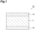
- a piezoelectric device 10 comprises a pair of electrodes 4a and 4b and a piezoelectric body 2 between the pair of electrodes 4a and 4b. That is, an electrode 4a overlaps one surface of the piezoelectric body 2, and a different electrode 4b overlaps the other surface of the piezoelectric body 2.
- a piezoelectric composition contained in the piezoelectric body 2 is represented by the following Chemical Formula (1).
- the piezoelectric body 2 may consist of only the piezoelectric composition represented by the following Chemical Formula (1).
- the piezoelectric body 2 may contain other ingredients in addition to the piezoelectric composition represented by the following Chemical Formula (1).
- the piezoelectric composition represented by the following Chemical Formula (1) may be a powder, or may be a sintered body.
- the piezoelectric composition represented by the above Chemical Formula (1) may have a perovskite-type crystal structure.
- the piezoelectric composition represented by the above Chemical Formula (1) may be a composite oxide represented by the following Chemical Formula (2).
- the piezoelectric body 2 may consist of only the piezoelectric composition represented by the following Chemical Formula (2).
- the piezoelectric body 2 may contain other ingredients in addition to the piezoelectric composition represented by the following Chemical Formula (2).
- a portion of the piezoelectric composition may be a phase consisting of Bi m FeO 3 .
- a portion of the piezoelectric composition may be a phase consisting of Ba m TiO 3 .
- a portion of the piezoelectric composition may be a phase consisting of Bi m AlO 3 .
- a portion of the piezoelectric composition may be a solid solution of at least two oxides selected from the group consisting of Bi m FeO 3 , Ba m TiO 3 and Bi m AlO 3 .
- the present inventors consider that a reason the d 33 and the specific resistance of the above piezoelectric composition are large is as follows.
- Bi is likely to volatilize.
- Bi is likely to volatilize.
- Bi is unlikely to be incorporated into the thin film in a growth process. Therefore, in conventional BiFeO 3 , which does not contain Al, Bi is likely to be deficient and the number of the valences of Fe at B sites is likely to change from trivalent to divalent.
- the piezoelectric composition according to this embodiment contains Al the number of the valence of which is unlikely to change. Therefore, some of B sites are replaced with Al, and a change in the numbers of the valences is likely to be suppressed. Consequently, the specific resistance of the piezoelectric composition according to this embodiment is larger than the specific resistance of conventional BiFeO 3 . Furthermore, when the specific resistance of the piezoelectric composition is large, leakage current becomes unlikely to occur at the time when a poling process is performed.
- the d 33 of the piezoelectric composition according to this embodiment is larger than the d 33 of conventional BiFeO 3 .
- Al is a relatively stable element, it is difficult to replace most of B sites in BiFeO 3 with Al.
- a phase (heterogeneous phase) consisting of Al is likely to be formed in a completed piezoelectric composition.
- Al in an amount such that the z becomes 0.2 is used as a raw material, a phase (heterogeneous phase) consisting of Al is likely to be formed in a completed piezoelectric composition.
- the domain inversion (polarization reversal) of the piezoelectric composition becomes unlikely to occur.
- the piezoelectric composition according to this embodiment is represented by the above Chemical Formula (1) and the z satisfies 0.0005 ⁇ z ⁇ 0.1, the domain inversion is likely to occur. Consequently, the d 33 of the piezoelectric composition according to this embodiment is larger than the d 33 of conventional BiFeO 3 .
- the reason the d 33 and the specific resistance of the piezoelectric composition according to this embodiment are large is not limited to the above reason.
- x satisfies 0.5 ⁇ x ⁇ 0.7995.
- the x is less than 0.5, the crystal structure of the piezoelectric composition shifts to a cubic crystal, and the d 33 of the piezoelectric composition is likely to become small.
- the x is more than 0.7995, the crystal structure of the piezoelectric composition shifts to a rhombohedral crystal, the polarization reversal is unlikely to occur, the d 33 of the piezoelectric composition becomes small, many defects at A sites are caused by the volatilization of Bi, and the specific resistance is likely to decrease.
- the x satisfy 0.65 ⁇ x ⁇ 0.75. Since the x is in the above numerical value range, the d 33 and the specific resistance of the piezoelectric composition are likely to become large.
- y satisfies 0.2 ⁇ y ⁇ 0.4.
- the crystal structure of a piezoelectric composition shifts to a rhombohedral crystal, the polarization reversal is unlikely to occur, the d 33 of a piezoelectric composition becomes small, many defects at A sites are caused by the volatilization of Bi, and the specific resistance is likely to decrease.
- the y is more than 0.4, the crystal structure of the piezoelectric composition shifts to a cubic crystal, and the d 33 of the piezoelectric composition is likely to become small.
- the y satisfy 0.25 ⁇ y ⁇ 0.35. Since the y is in the above numerical value range, the d 33 and the specific resistance of the piezoelectric composition are likely to become large.
- z satisfies 0.0005 ⁇ z ⁇ 0.1.
- the z is less than 0.0005
- a fluctuation in the numbers of the valences of Fe at B sites cannot be suppressed, and the specific resistance is likely to decrease.
- the z is more than 0.1
- the content of Al exceeds the solid-solution limit of Al, and heterogeneous phases containing Al are formed in grain boundaries. Consequently, the d 33 of the piezoelectric composition is likely to become small.
- the z satisfy 0.0005 ⁇ z ⁇ 0.05. Since the z is in the above numerical value range, the d 33 and the specific resistance of the piezoelectric composition are likely to become large.
- the m satisfies 0.96 ⁇ m ⁇ 1.04.
- the m is less than 0.96, Bi and Ba, which are at A sites, decrease, defects at A sites increase, and the specific resistance is likely to decrease.
- the m is more than 1.04, heterogeneous phases containing either of Bi and Ba are formed in grain boundaries, and the d 33 of the piezoelectric composition is likely to become small. It is preferable that the m satisfy 0.98 ⁇ m ⁇ 1.02. When the m is in the above numerical value range, the d 33 and the specific resistance of a piezoelectric composition are likely to become large.
- the above Chemical Formula (2) is represented as A m BO 3 .
- the m is the ratio [A]/[B] of the number [A] of all atoms occupying A sites to the number [B] of all atoms occupying B sites.
- the m namely the [A]/[B] greatly deviates from a stoichiometric ratio of 1, and therefore defects in the piezoelectric composition are likely to increase and heterogeneous phases are likely to increase in grain boundaries, thereby the d 33 and the specific resistance of the piezoelectric composition are likely to become small.
- FIG. 2 is a schematic view illustrating the constitutions of the piezoelectric compositions according to this embodiment.
- BF means BiFeO 3 in FIG. 2 .
- BT means BaTiO 3 .
- BA means BiAlO 3 .
- the constitutions of the piezoelectric compositions are illustrated by coordinates (x, y, z) in FIG. 2 .
- Coordinates ⁇ (x, y, z) are (0.5995, 0.4, 0.0005).
- Coordinates ⁇ (x, y, z) are (0.5, 0.4, 0.1).
- Coordinates y (x, y, z) are (0.7995, 0.2, 0.0005).
- Coordinates ⁇ (x, y, z) are (0.7, 0.2, 0.1).
- a range surrounded by dotted lines connecting the coordinates ⁇ , ⁇ , y and ⁇ is defined as a range A.
- the range A is in the range of the constitutions of
- the piezoelectric composition may contain other elements than the elements contained in the above Chemical Formula (1) as impurities or minute amounts of additives in the form of compounds or simple substances.
- examples of such a compound include oxides of Na, Al, Si, P, K, Fe, Cu, Zn, Hf, Ta, or W.
- the piezoelectric composition contains these oxides and the like, it is preferable that the total content of oxides in the piezoelectric composition be 0.3 % by mass or less of the whole piezoelectric composition in terms of oxides of the elements. That is, it is preferable that the main ingredient, specifically 99.7% by mass or more of the whole piezoelectric composition, have the constitution represented by Chemical Formula (1). In this case, the piezoelectric composition substantially has the constitution represented by Chemical Formula (1).
- the constitution of the piezoelectric composition can be measured, for example, by an X-ray fluorescence analysis (XRF method).
- XRF method X-ray fluorescence analysis
- the piezoelectric device 10 comprises the piezoelectric body 2 containing the piezoelectric composition represented by the above Chemical Formula (1), it is excellent in piezoelectric characteristics.
- the piezoelectric body 2 may be a sintered body containing the above piezoelectric composition, or may be a thin film containing the above piezoelectric composition.
- the potential difference between a pair of electrodes 4a and 4b may be, for example, 0.1 to 2.0 kV/mm.
- a piezoelectric device using conventional BiFeO 3 as long as the potential difference between the electrodes of the piezoelectric device is not a high voltage of 5.0 kV/mm or more, enough piezoelectric characteristics are not obtained. Meanwhile, in the piezoelectric device 10 according to this embodiment, even if the potential difference between the electrodes 4a and 4b is a low voltage in the above numerical value range or a high voltage higher than the above numerical value range, enough piezoelectric characteristics can be obtained.
- the method for manufacturing the piezoelectric device 10 comprises: a mixing step of granulating a raw material powder of the piezoelectric body 2 containing the above piezoelectric composition; a sintering step of press-forming this raw material powder to form a formed body and sintering the formed body to produce a sintered body; and a polarization step of performing a poling process on the sintered body to obtain the piezoelectric device 10. Steps will be described specifically hereinafter.
- starting raw materials for preparing the piezoelectric composition are first provided.
- oxides of elements that constitute the piezoelectric composition represented by the above Chemical Formula (1) or compounds that become these oxides after sintering carbonates, hydroxides, oxalates, nitrates and the like
- specific starting raw materials a Bi (bismuth) compound, a Fe (iron) compound, a Ba (barium) compound, a Ti (titanium) compound, an Al (aluminum) compound and the like may be used.
- These starting raw materials are blended at a molar ratio or a mass ratio such that the piezoelectric composition represented by the above Chemical Formula (1) is formed after sintering, and wet mixing is conducted by a ball mill or the like.
- the Bi compound may be bismuth oxide (Bi 2 O 3 ), bismuth nitrate (Bi(NO 3 ) 3 ) or the like.
- the Fe compound may be iron oxide (Fe 2 O 3 ), iron chloride (FeCl 3 ), iron nitrate (Fe(NO 3 ) 3 ) or the like.
- the Ba compound may be barium oxide (BaO), barium carbonate (BaCO 3 ), barium oxalate (C 2 BaO 4 ), barium acetate ((CH 3 COO) 2 Ba), barium nitrate (Ba(NO 3 ) 2 ), barium sulfate (BaSO 4 ), barium titanate (BaTiO 3 ) or the like.
- the Ti compound may be titanium oxide (TiO 2 ) or the like.
- the Al compound may be aluminum oxide (Al 2 O 3 ) or the like.
- the mixed raw material obtained by wet mixing is temporarily formed into a temporarily formed body, which is then calcined.
- a calcined body containing the above piezoelectric composition is obtained by this calcination.
- the calcination temperature be 600 to 900°C, and it is preferable that the calcination time be around 1 to 16 hours.
- the calcination temperature is too low, a chemical reaction tends not to proceed fully in the temporarily formed body.
- the calcination temperature is too high, a temporarily formed body begins to sinter, and subsequent pulverization therefore tends to become difficult.
- Calcination may be performed in the air atmosphere, and may be performed in an atmosphere in which the partial pressure of oxygen is higher than that in the air, or a pure oxygen atmosphere.
- the wet-mixed starting raw material may be calcined without being temporarily formed.
- the obtained calcined body is slurried and pulverized (wet ground) by a ball mill or the like, and thereafter a fine powder is obtained by drying the slurry.
- a binder is added to the obtained fine powder if needed, and the raw material powder is granulated. It is preferable to use water, an alcohol such as ethanol, a mixed solvent of water and ethanol, or the like as a solvent for slurrying a calcined body.
- Binders added to the fine powder include commonly used organic binders such as polyvinyl alcohol, polyvinyl alcohol to which a dispersing agent is added, ethyl cellulose, and the like.
- a formed body is formed by press-forming the granulated raw material powder.
- a load at the time of press-forming may be adjusted, for example, to 1.0 to 3.5 MPa.
- binder removal treatment is provided to the obtained formed body. It is preferable that the binder removal treatment be performed at a temperature of 400 to 800°C for around 2 to 4 hours.
- the binder removal treatment may be performed in the air atmosphere, or may be performed in an atmosphere in which the partial pressure of oxygen is higher than that in the air, or a pure oxygen atmosphere.
- a sintered body containing the piezoelectric composition represented by the above Chemical Formula (1) is obtained by sintering the formed body after the binder removal treatment.
- the sintering temperature may be about 900 to 1100°C, and the sintering time may be adjusted to around 2 to 20 hours.
- the binder removal treatment and the sintering of the formed body may be performed successively, or may be performed separately.
- the surface of the obtained sintered body is polished if needed, and the sintered body is processed such that the sintered body is cut to form the desired shape of a piezoelectric body 2.
- a pair of electrodes 4a and 4b is formed on both surfaces of the processed sintered body.
- the electrodes 4a and 4b may be formed by applying and baking an electrode paste, or may be formed by vapor deposition or sputtering film formation.
- a piezoelectric device 10 according to this embodiment can be obtained by impressing a polarization electric field on the sintered body on which the electrodes are formed and performing a poling process.
- the conditions of the poling process may be properly determined depending on the constitution of the piezoelectric composition that the sintered body contains.
- the conditions of the poling process may be, for example, as follows.
- the sintered body may be immersed into silicone oil at 25 to 200°C.
- the time to impress a polarization electric field may be 5 to 60 minutes.
- the magnitude of a polarization electric field may be 1.2 or more times greater than that of the coercive electric field of the sintered body.
- the uses of a piezoelectric composition are various.
- the piezoelectric composition may be applied, for example, to a radiator, a resonator, an actuator, a motor or a sensor.
- the specific use of the piezoelectric composition may be, for example, a SAW filter, a BAW filter, a piezoelectric microphone, a head assembly, a hard disk drive, a printer head, an ink jet printer device, an ultrasonic washing machine, an ultrasonic motor, an atomizer oscillator, a fish finder, a shocking sensor, an ultrasonic diagnostic device, a waste toner sensor, a gyro sensor, a buzzer, a transformer, or a lighter.
- a piezoelectric device was manufactured by a method illustrated below.
- raw materials of the piezoelectric composition raw material powders of bismuth oxide (Bi 2 O 3 ), iron oxide (Fe 2 O 3 ), barium carbonate (BaCO 3 ), titanium oxide (TiO 2 ) and aluminum oxide (Al 2 O 3 ) were provided. These raw material powders were weighed and blended, and the mixed raw material was prepared such that a sintered body after the final sintering became a piezoelectric composition represented by the following Chemical Formula (3).
- the prepared mixed raw material and pure water were mixed with Zr balls by a ball mill for 10 hours to obtain slurry.
- This slurry was fully dried, thereafter press-formed and calcined at 800°C to obtain a calcined body.
- the calcined body was pulverized by the ball mill and thereafter dried, a proper amount of PVA (polyvinyl alcohol) was added thereto as a binder, and the mixture was granulated.
- PVA polyvinyl alcohol
- the molded sample was heat-treated to remove the binder therefrom and thereafter finally sintered at 950 to 1100°C for 4 hours to obtain a sintered body.
- the obtained sintered body was flattened to a thickness of 0.5 mm with a double-side lapping machine and thereafter cut to a size of 16mm in length by 16mm in width with a dicing saw. Subsequently, electrodes 4a and 4b were formed on both surfaces of the sintered body by using a vacuum evaporator.
- the electrodes 4a and 4b were composed of 1.5- ⁇ m Ag layers. The sizes of the electrodes were 15 mm by 15 mm.
- Example 1 The constitution of the sintered body in Example 1 was analyzed by an X-ray fluorescence analysis (XRF method). Consequently, it has been confirmed that the constitution of the sintered body in Example 1 is represented by the above Chemical Formula (3).
- XRF method X-ray fluorescence analysis
- the d 33 (unit: pC/N) of the sintered body (piezoelectric composition) in Example 1 before the forming of temporary electrodes was measured by using a d 33 meter.
- the above d 33 meter measures d 33 by the Berlincourt method based on JIS R 1696.
- the d 33 is measured by utilizing a piezoelectric positive effect at the time when vibration is given to a piezoelectric composition. Therefore, in the Berlincourt method, there is no influence of electrostriction differently from a measuring method in which a piezoelectric reverse effect at the time when an electric field is impressed on a piezoelectric composition is utilized, and the original d 33 of a piezoelectric composition is obtained.
- the d 33 in Example 1 is illustrated in Table 2.
- the d 33 is good when it is 150 pC/N or more.
- Direct-current voltage was impressed between the electrode 4a and the electrode 4b in the piezoelectric device in Example 1, and the specific resistance (unit: ⁇ cm) between the electrode 4a and the electrode 4b was measured.
- the direct-current voltage was 40 V.
- the specific resistance in Example 1 is illustrated in Table 2. The specific resistance is good when it is 1.0 ⁇ 10 9 ⁇ cm or more.
- Respective piezoelectric devices in Examples 2 to 29 and Comparative Examples 1 to 26 were individually manufactured by the same method as Example 1 except that the ratios of powder raw materials blended were altered such that x, y, z, and m in the above Chemical Formula (3) became values illustrated in the following Tables 1 to 8 when mixed raw materials were prepared.
- the respective constitutions of the sintered bodies in Examples 2 to 29 and Comparative Examples 1 to 26 were analyzed by the same method as Example 1. Consequently, it has been confirmed that the respective constitutions of the sintered bodies in Examples 2 to 29 and Comparative Examples 1 to 26 are the constitutions illustrated in Tables 1 to 8.
- the d 33 s of Examples 2 to 29 and Comparative Examples 1 to 26 were measured individually by the same method as Example 1.
- Example 2 to 29 and Comparative Examples 1 to 26 are illustrated in Tables 1 to 8.
- the specific resistances in Examples 2 to 29 and the Comparative Examples 1 to 26 were measured individually by the same method as Example 1.
- the specific resistances in Examples 2 to 29 and Comparative Examples 1 to 26 are illustrated in Tables 1 to 8.
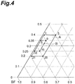
- FIGS. 3 and 4 are enlarged views of portions of FIG. 2 .
- the coordinates of a round mark indicate the constitution of a piezoelectric composition in Example or Comparative Example.
- a number appended to a round mark is the number of Example.
- the coordinates (x, y, z) of Example 1 are the same as the coordinates ⁇ in FIG. 2 , and are (0.5995, 0.4, 0.0005).
- the coordinates (x, y, z) of Example 5 are the same as the coordinates ⁇ in FIG. 2 , and are (0.5, 0.4, 0.1).
- the coordinates (x, y, z) of Example 21 are the same as the coordinates y in FIG.
- Example 2 and are (0.7995, 0.2, 0.0005).
- the coordinates (x, y, z) of Example 25 are the same as the coordinates ⁇ in FIG. 2 , and are (0.7, 0.2, 0.1).
- a range surrounded by dotted lines connecting the coordinates of Examples 1, 5, 21 and 25 is the same as the range A in FIG. 2 .
- the coordinates (x, y, z) of Example 6 are (0.6495, 0.35, 0.0005).
- the coordinates (x, y, z) of Example 9 are (0.6, 0.35, 0.05).
- the coordinates (x, y, z) of Example 16 are (0.7495, 0.25, 0.0005).
- the coordinates (x, y, z) of Example 19 are (0.7, 0.25, 0.05).
- a range surrounded by dashed lines connecting the coordinates of Examples 6, 9, 16 and 19 is defined as a range B.
- the piezoelectric compositions belonging to the range B are superior to the piezoelectric compositions belonging to the above range A in the point that at least either of the d 33 and the specific resistance is likely to become large.
- the d 33 s of all the Examples were 150 pC/N or more, and the specific resistances of all the Examples were 1.0 ⁇ 10 9 ⁇ cm or more. Meanwhile, there was no Comparative Examples the d 33 s of which were 150 pC/N or more and the specific resistances of which were 1.0 ⁇ 10 9 ⁇ cm or more. It has been confirmed that a piezoelectric composition the d 33 of which is large and the specific resistance of which is large and a piezoelectric device using the piezoelectric composition are provided according to the present invention.
Landscapes
- Chemical & Material Sciences (AREA)
- Engineering & Computer Science (AREA)
- Ceramic Engineering (AREA)
- Manufacturing & Machinery (AREA)
- Organic Chemistry (AREA)
- Inorganic Chemistry (AREA)
- Materials Engineering (AREA)
- Structural Engineering (AREA)
- Chemical Kinetics & Catalysis (AREA)
- Compositions Of Oxide Ceramics (AREA)
Abstract
x[BimFeO3]-y[BamTiO3]-z[BimAlO3] (1)
wherein 0.5 ≤ x ≤ 0.7995, 0.2 ≤ y ≤ 0.4, 0.0005 ≤ z ≤ 0.1, x + y + z = 1, 0.96 ≤ m ≤ 1.04.
Description
- The present invention relates to a piezoelectric composition and a piezoelectric device.
- A perovskite-type metal oxide is known as a common piezoelectric composition. The constitution of a perovskite-type metal oxide is represented by ABO3. A perovskite-type piezoelectric composition is, for example, lead zirconate titanate (Pb(Zr, Ti)O3). The curie temperature (Tc) of lead zirconate titanate (PZT) is high, and the piezoelectric constant (d33) of PZT is large. However, PZT does harm to the environment or the human body due to containing lead as an element at A sites. The piezoelectric composition not containing lead is required in view of influence on the environment or the human body.
- An example of the piezoelectric composition not containing lead is bismuth ferrite (BiFeO3) described in the following
Non Patent Literature 1. The Tc of bismuth ferrite (BFO) is high, and BFO exhibits large spontaneous polarization. However, in the case of BFO alone, enough piezoelectric performance (for example, d33) is not obtained due to the anisotropy being high, the leakage current being large and the like. - Therefore, a piezoelectric composition the Tc of which is high and the d33 of which is large is required. A binary compound composed of barium titanate and bismuth ferrite is disclosed in the following
Non Patent Literature 2. A ternary compound composed of barium titanate, bismuth ferrite and a composite oxide such as bismuth magnesate titanate is disclosed in Japanese Unexamined Patent Publication2013-191751 - [Non Patent literature 1] Tadej Rojac et al., "Strong ferroelectric domain-wall pinning in BiFeO3 ceramics", JOURNAL OF APPLIED PHYSICS, 108, 074107, 2010.
- [Non Patent literature 2] Zhenyong Cen et al., "Effect of sintering temperature on microstructure and piezoelectric properties of Pb-free BiFeO3-BaTiO3 ceramics in the composition range of large BiFeO3 concentrations", J Electroceram, 31, p. 15-20, 2013.
- A piezoelectric composition described in Japanese Unexamined Patent Publication
2013-191751 2013-191751 Non Patent Literature 2, the d33 of the piezoelectric composition after the poling process is around 130 pC/N, and is small. - Therefore, the present invention has been completed in view of the above circumstances, and an object of the present invention is to provide a piezoelectric composition the d33 of which is large and the specific resistance of which is large and a piezoelectric device using the piezoelectric composition.
- A piezoelectric composition according to one aspect of the present invention is represented by the following Chemical Formula (1):
x[BimFeO3]-y[BamTiO3]-z[BimAlO3] (1)
wherein 0.5 ≤ x ≤ 0.7995, 0.2 ≤ y ≤ 0.4, 0.0005 ≤ z ≤ 0.1, x + y + z = 1, and 0.96 ≤ m ≤ 1.04. - A piezoelectric device according to one aspect of the present invention comprises the above piezoelectric composition.
- According to the present invention, a piezoelectric composition the d33 of which is large and the specific resistance of which is large and a piezoelectric device using the piezoelectric composition are provided.
-
-
FIG. 1 is a sectional view of a piezoelectric device according to one embodiment of the present invention. -
FIG. 2 is a schematic view illustrating the constitutions of piezoelectric compositions according to one embodiment of the present invention. -
FIG. 3 is an enlarged view of a portion ofFIG. 2 , and is a schematic view illustrating the constitutions of piezoelectric compositions in Examples and Comparative Examples. -
FIG. 4 is an enlarged view of a portion ofFIG. 2 , and is a schematic view illustrating the constitutions of piezoelectric compositions in Examples. - Preferred embodiments of the present invention will be described in detail hereinafter with proper reference to the drawings. In the drawings, the identical or equivalent components are indicated with the identical reference sign. When a description overlaps, the description is omitted. The present invention is not limited to the following embodiments.
- As shown in
FIG. 1 , apiezoelectric device 10 according to this embodiment comprises a pair ofelectrodes piezoelectric body 2 between the pair ofelectrodes electrode 4a overlaps one surface of thepiezoelectric body 2, and adifferent electrode 4b overlaps the other surface of thepiezoelectric body 2. - A piezoelectric composition contained in the
piezoelectric body 2 is represented by the following Chemical Formula (1). Thepiezoelectric body 2 may consist of only the piezoelectric composition represented by the following Chemical Formula (1). Thepiezoelectric body 2 may contain other ingredients in addition to the piezoelectric composition represented by the following Chemical Formula (1). The piezoelectric composition represented by the following Chemical Formula (1) may be a powder, or may be a sintered body.
x[BimFeO3]-y[BamTiO3]-z[BimAlO3] (1)
[In Formula (1), 0.5 ≤ x ≤ 0.7995, 0.2 ≤ y ≤ 0.4, 0.0005 ≤ z ≤ 0.1, x + y + z = 1, 0.96 ≤ m ≤ 1.04]. - The piezoelectric composition represented by the above Chemical Formula (1) may have a perovskite-type crystal structure. The piezoelectric composition represented by the above Chemical Formula (1) may be a composite oxide represented by the following Chemical Formula (2). The
piezoelectric body 2 may consist of only the piezoelectric composition represented by the following Chemical Formula (2). Thepiezoelectric body 2 may contain other ingredients in addition to the piezoelectric composition represented by the following Chemical Formula (2).
(Bi(x+z)Bay)m(FexTiyAlz)O3 (2)
[In Formula (2), 0.5 ≤ x ≤ 0.7995, 0.2 ≤ y ≤ 0.4, 0.0005 ≤ z ≤ 0.1, x + y + z = 1, and 0.96 ≤ m ≤ 1.04]. - A portion of the piezoelectric composition may be a phase consisting of BimFeO3. A portion of the piezoelectric composition may be a phase consisting of BamTiO3. A portion of the piezoelectric composition may be a phase consisting of BimAlO3. A portion of the piezoelectric composition may be a solid solution of at least two oxides selected from the group consisting of BimFeO3, BamTiO3 and BimAlO3.
- The present inventors consider that a reason the d33 and the specific resistance of the above piezoelectric composition are large is as follows. In a process of sintering perovskite-type BiFeO3 to form the
piezoelectric body 2, Bi is likely to volatilize. Also in a process of forming a thin film containing BiFeO3, Bi is likely to volatilize. For example, when a thin film is formed by a sputtering method, Bi is unlikely to be incorporated into the thin film in a growth process. Therefore, in conventional BiFeO3, which does not contain Al, Bi is likely to be deficient and the number of the valences of Fe at B sites is likely to change from trivalent to divalent. When the numbers of the valences of Fe change from trivalent to divalent, charge transfer occurs, and the specific resistance of BiFeO3 becomes small. Meanwhile, the piezoelectric composition according to this embodiment contains Al the number of the valence of which is unlikely to change. Therefore, some of B sites are replaced with Al, and a change in the numbers of the valences is likely to be suppressed. Consequently, the specific resistance of the piezoelectric composition according to this embodiment is larger than the specific resistance of conventional BiFeO3. Furthermore, when the specific resistance of the piezoelectric composition is large, leakage current becomes unlikely to occur at the time when a poling process is performed. Consequently, the d33 of the piezoelectric composition according to this embodiment is larger than the d33 of conventional BiFeO3. Since Al is a relatively stable element, it is difficult to replace most of B sites in BiFeO3 with Al. Furthermore, when a large amount of Al is added to the raw materials of BiFeO3, a phase (heterogeneous phase) consisting of Al is likely to be formed in a completed piezoelectric composition. For example, Al in an amount such that the z becomes 0.2 is used as a raw material, a phase (heterogeneous phase) consisting of Al is likely to be formed in a completed piezoelectric composition. Consequently, the domain inversion (polarization reversal) of the piezoelectric composition becomes unlikely to occur. Meanwhile, since the piezoelectric composition according to this embodiment is represented by the above Chemical Formula (1) and the z satisfies 0.0005 ≤ z ≤ 0.1, the domain inversion is likely to occur. Consequently, the d33 of the piezoelectric composition according to this embodiment is larger than the d33 of conventional BiFeO3. In addition, the reason the d33 and the specific resistance of the piezoelectric composition according to this embodiment are large is not limited to the above reason. - In the above chemical formula (1), x satisfies 0.5 ≤ x ≤ 0.7995. When the x is less than 0.5, the crystal structure of the piezoelectric composition shifts to a cubic crystal, and the d33 of the piezoelectric composition is likely to become small. When the x is more than 0.7995, the crystal structure of the piezoelectric composition shifts to a rhombohedral crystal, the polarization reversal is unlikely to occur, the d33 of the piezoelectric composition becomes small, many defects at A sites are caused by the volatilization of Bi, and the specific resistance is likely to decrease. It is preferable that the x satisfy 0.65 ≤ x ≤ 0.75. Since the x is in the above numerical value range, the d33 and the specific resistance of the piezoelectric composition are likely to become large.
- In the above Chemical Formula (1), y satisfies 0.2 ≤ y ≤ 0.4. When the y is less than 0.2, the crystal structure of a piezoelectric composition shifts to a rhombohedral crystal, the polarization reversal is unlikely to occur, the d33 of a piezoelectric composition becomes small, many defects at A sites are caused by the volatilization of Bi, and the specific resistance is likely to decrease. When the y is more than 0.4, the crystal structure of the piezoelectric composition shifts to a cubic crystal, and the d33 of the piezoelectric composition is likely to become small. It is preferable that the y satisfy 0.25 ≤ y ≤ 0.35. Since the y is in the above numerical value range, the d33 and the specific resistance of the piezoelectric composition are likely to become large.
- In the above Chemical Formula (1), z satisfies 0.0005 ≤ z ≤ 0.1. When the z is less than 0.0005, a fluctuation in the numbers of the valences of Fe at B sites cannot be suppressed, and the specific resistance is likely to decrease. When the z is more than 0.1, the content of Al exceeds the solid-solution limit of Al, and heterogeneous phases containing Al are formed in grain boundaries. Consequently, the d33 of the piezoelectric composition is likely to become small. It is preferable that the z satisfy 0.0005 ≤ z ≤ 0.05. Since the z is in the above numerical value range, the d33 and the specific resistance of the piezoelectric composition are likely to become large.
- In the above Chemical Formula (1), the m satisfies 0.96 ≤ m ≤ 1.04. When the m is less than 0.96, Bi and Ba, which are at A sites, decrease, defects at A sites increase, and the specific resistance is likely to decrease. When the m is more than 1.04, heterogeneous phases containing either of Bi and Ba are formed in grain boundaries, and the d33 of the piezoelectric composition is likely to become small. It is preferable that the m satisfy 0.98 ≤ m ≤ 1.02. When the m is in the above numerical value range, the d33 and the specific resistance of a piezoelectric composition are likely to become large.
- The above Chemical Formula (2) is represented as AmBO3. The m is the ratio [A]/[B] of the number [A] of all atoms occupying A sites to the number [B] of all atoms occupying B sites. When the m is out of the above numerical value range, the m, namely the [A]/[B], greatly deviates from a stoichiometric ratio of 1, and therefore defects in the piezoelectric composition are likely to increase and heterogeneous phases are likely to increase in grain boundaries, thereby the d33 and the specific resistance of the piezoelectric composition are likely to become small.
-
FIG. 2 is a schematic view illustrating the constitutions of the piezoelectric compositions according to this embodiment. BF means BiFeO3 inFIG. 2 . BT means BaTiO3. BA means BiAlO3. The constitutions of the piezoelectric compositions are illustrated by coordinates (x, y, z) inFIG. 2 . Coordinates α (x, y, z) are (0.5995, 0.4, 0.0005). Coordinates β (x, y, z) are (0.5, 0.4, 0.1). Coordinates y (x, y, z) are (0.7995, 0.2, 0.0005). Coordinates δ (x, y, z) are (0.7, 0.2, 0.1). A range surrounded by dotted lines connecting the coordinates α, β, y and δ is defined as a range A. The range A is in the range of the constitutions of the piezoelectric compositions according to the present invention. - The piezoelectric composition may contain other elements than the elements contained in the above Chemical Formula (1) as impurities or minute amounts of additives in the form of compounds or simple substances. Examples of such a compound include oxides of Na, Al, Si, P, K, Fe, Cu, Zn, Hf, Ta, or W. When the piezoelectric composition contains these oxides and the like, it is preferable that the total content of oxides in the piezoelectric composition be 0.3 % by mass or less of the whole piezoelectric composition in terms of oxides of the elements. That is, it is preferable that the main ingredient, specifically 99.7% by mass or more of the whole piezoelectric composition, have the constitution represented by Chemical Formula (1). In this case, the piezoelectric composition substantially has the constitution represented by Chemical Formula (1).
- The constitution of the piezoelectric composition can be measured, for example, by an X-ray fluorescence analysis (XRF method).
- Since the
piezoelectric device 10 comprises thepiezoelectric body 2 containing the piezoelectric composition represented by the above Chemical Formula (1), it is excellent in piezoelectric characteristics. Thepiezoelectric body 2 may be a sintered body containing the above piezoelectric composition, or may be a thin film containing the above piezoelectric composition. - The potential difference between a pair of
electrodes piezoelectric device 10 according to this embodiment, even if the potential difference between theelectrodes - Then, an example of a method for manufacturing the
piezoelectric device 10 according to this embodiment will be described. The method for manufacturing thepiezoelectric device 10 comprises: a mixing step of granulating a raw material powder of thepiezoelectric body 2 containing the above piezoelectric composition; a sintering step of press-forming this raw material powder to form a formed body and sintering the formed body to produce a sintered body; and a polarization step of performing a poling process on the sintered body to obtain thepiezoelectric device 10. Steps will be described specifically hereinafter. - In a mixing step, starting raw materials for preparing the piezoelectric composition are first provided. As the starting raw materials, oxides of elements that constitute the piezoelectric composition represented by the above Chemical Formula (1) or compounds that become these oxides after sintering (carbonates, hydroxides, oxalates, nitrates and the like) can be used. As specific starting raw materials, a Bi (bismuth) compound, a Fe (iron) compound, a Ba (barium) compound, a Ti (titanium) compound, an Al (aluminum) compound and the like may be used. These starting raw materials are blended at a molar ratio or a mass ratio such that the piezoelectric composition represented by the above Chemical Formula (1) is formed after sintering, and wet mixing is conducted by a ball mill or the like.
- The Bi compound may be bismuth oxide (Bi2O3), bismuth nitrate (Bi(NO3)3) or the like. The Fe compound may be iron oxide (Fe2O3), iron chloride (FeCl3), iron nitrate (Fe(NO3)3) or the like. The Ba compound may be barium oxide (BaO), barium carbonate (BaCO3), barium oxalate (C2BaO4), barium acetate ((CH3COO)2Ba), barium nitrate (Ba(NO3)2), barium sulfate (BaSO4), barium titanate (BaTiO3) or the like. The Ti compound may be titanium oxide (TiO2) or the like. The Al compound may be aluminum oxide (Al2O3) or the like.
- Then, the mixed raw material obtained by wet mixing is temporarily formed into a temporarily formed body, which is then calcined. A calcined body containing the above piezoelectric composition is obtained by this calcination. It is preferable that the calcination temperature be 600 to 900°C, and it is preferable that the calcination time be around 1 to 16 hours. When the calcination temperature is too low, a chemical reaction tends not to proceed fully in the temporarily formed body. When the calcination temperature is too high, a temporarily formed body begins to sinter, and subsequent pulverization therefore tends to become difficult. Calcination may be performed in the air atmosphere, and may be performed in an atmosphere in which the partial pressure of oxygen is higher than that in the air, or a pure oxygen atmosphere. Furthermore, the wet-mixed starting raw material may be calcined without being temporarily formed.
- Then, the obtained calcined body is slurried and pulverized (wet ground) by a ball mill or the like, and thereafter a fine powder is obtained by drying the slurry. A binder is added to the obtained fine powder if needed, and the raw material powder is granulated. It is preferable to use water, an alcohol such as ethanol, a mixed solvent of water and ethanol, or the like as a solvent for slurrying a calcined body. Binders added to the fine powder include commonly used organic binders such as polyvinyl alcohol, polyvinyl alcohol to which a dispersing agent is added, ethyl cellulose, and the like.
- In a sintering step, a formed body is formed by press-forming the granulated raw material powder. A load at the time of press-forming may be adjusted, for example, to 1.0 to 3.5 MPa.
- Then, binder removal treatment is provided to the obtained formed body. It is preferable that the binder removal treatment be performed at a temperature of 400 to 800°C for around 2 to 4 hours. The binder removal treatment may be performed in the air atmosphere, or may be performed in an atmosphere in which the partial pressure of oxygen is higher than that in the air, or a pure oxygen atmosphere.
- A sintered body containing the piezoelectric composition represented by the above Chemical Formula (1) is obtained by sintering the formed body after the binder removal treatment. The sintering temperature may be about 900 to 1100°C, and the sintering time may be adjusted to around 2 to 20 hours. The binder removal treatment and the sintering of the formed body may be performed successively, or may be performed separately.
- The surface of the obtained sintered body is polished if needed, and the sintered body is processed such that the sintered body is cut to form the desired shape of a
piezoelectric body 2. A pair ofelectrodes electrodes - A
piezoelectric device 10 according to this embodiment can be obtained by impressing a polarization electric field on the sintered body on which the electrodes are formed and performing a poling process. The conditions of the poling process may be properly determined depending on the constitution of the piezoelectric composition that the sintered body contains. The conditions of the poling process may be, for example, as follows. The sintered body may be immersed into silicone oil at 25 to 200°C. The time to impress a polarization electric field may be 5 to 60 minutes. The magnitude of a polarization electric field may be 1.2 or more times greater than that of the coercive electric field of the sintered body. - The uses of a piezoelectric composition according to this embodiment are various. The piezoelectric composition may be applied, for example, to a radiator, a resonator, an actuator, a motor or a sensor. The specific use of the piezoelectric composition may be, for example, a SAW filter, a BAW filter, a piezoelectric microphone, a head assembly, a hard disk drive, a printer head, an ink jet printer device, an ultrasonic washing machine, an ultrasonic motor, an atomizer oscillator, a fish finder, a shocking sensor, an ultrasonic diagnostic device, a waste toner sensor, a gyro sensor, a buzzer, a transformer, or a lighter.
- As mentioned above, preferable embodiments of the present invention were described, but the present invention is not necessarily limited to the embodiments mentioned above. Various modifications of the present invention are possible as long as the modifications do not deviate from aims of the present invention, and these modification examples are included in the present invention.
- The present invention will be described in detail by using Examples and Comparative Example hereinafter. However, the present invention is not limited to the following Examples at all.
- A piezoelectric device was manufactured by a method illustrated below. As raw materials of the piezoelectric composition, raw material powders of bismuth oxide (Bi2O3), iron oxide (Fe2O3), barium carbonate (BaCO3), titanium oxide (TiO2) and aluminum oxide (Al2O3) were provided. These raw material powders were weighed and blended, and the mixed raw material was prepared such that a sintered body after the final sintering became a piezoelectric composition represented by the following Chemical Formula (3).
x[BimFeO3]-y[BamTiO3]-z[BimAlO3] (3)
In the above Chemical Formula (3), x = 0.5995, y = 0.4, z = 0.0005, and m = 1.02. - Then, the prepared mixed raw material and pure water were mixed with Zr balls by a ball mill for 10 hours to obtain slurry. This slurry was fully dried, thereafter press-formed and calcined at 800°C to obtain a calcined body. Next, the calcined body was pulverized by the ball mill and thereafter dried, a proper amount of PVA (polyvinyl alcohol) was added thereto as a binder, and the mixture was granulated. Around 3 g of the obtained granulated powder was placed into a metal mold of 20mm in length by 20mm in width and formed under a load of 3.2 MPa by using a uniaxial press molding machine.
- The molded sample was heat-treated to remove the binder therefrom and thereafter finally sintered at 950 to 1100°C for 4 hours to obtain a sintered body.
- The obtained sintered body was flattened to a thickness of 0.5 mm with a double-side lapping machine and thereafter cut to a size of 16mm in length by 16mm in width with a dicing saw. Subsequently,
electrodes electrodes - Thereafter, a poling process in which 1.5 to 2 times as strong an electric field as the coercive electric field was impressed on the sintered body on which the electrodes were formed in a silicone oil bath at a temperature of 120°C for 15 minutes was performed to obtain a
piezoelectric device 10 having the same configuration asFIG. 1 . - The constitution of the sintered body in Example 1 was analyzed by an X-ray fluorescence analysis (XRF method). Consequently, it has been confirmed that the constitution of the sintered body in Example 1 is represented by the above Chemical Formula (3).
- The d33 (unit: pC/N) of the sintered body (piezoelectric composition) in Example 1 before the forming of temporary electrodes was measured by using a d33 meter. The above d33 meter measures d33 by the Berlincourt method based on JIS R 1696. In the Berlincourt method, the d33 is measured by utilizing a piezoelectric positive effect at the time when vibration is given to a piezoelectric composition. Therefore, in the Berlincourt method, there is no influence of electrostriction differently from a measuring method in which a piezoelectric reverse effect at the time when an electric field is impressed on a piezoelectric composition is utilized, and the original d33 of a piezoelectric composition is obtained. The d33 in Example 1 is illustrated in Table 2. The d33 is good when it is 150 pC/N or more.
- Direct-current voltage was impressed between the
electrode 4a and theelectrode 4b in the piezoelectric device in Example 1, and the specific resistance (unit: Ω·cm) between theelectrode 4a and theelectrode 4b was measured. The direct-current voltage was 40 V. The specific resistance in Example 1 is illustrated in Table 2. The specific resistance is good when it is 1.0 × 10⁹ Ω·cm or more. - Respective piezoelectric devices in Examples 2 to 29 and Comparative Examples 1 to 26 were individually manufactured by the same method as Example 1 except that the ratios of powder raw materials blended were altered such that x, y, z, and m in the above Chemical Formula (3) became values illustrated in the following Tables 1 to 8 when mixed raw materials were prepared. The respective constitutions of the sintered bodies in Examples 2 to 29 and Comparative Examples 1 to 26 were analyzed by the same method as Example 1. Consequently, it has been confirmed that the respective constitutions of the sintered bodies in Examples 2 to 29 and Comparative Examples 1 to 26 are the constitutions illustrated in Tables 1 to 8. The d33s of Examples 2 to 29 and Comparative Examples 1 to 26 were measured individually by the same method as Example 1. The d33s of Examples 2 to 29 and Comparative Examples 1 to 26 are illustrated in Tables 1 to 8. The specific resistances in Examples 2 to 29 and the Comparative Examples 1 to 26 were measured individually by the same method as Example 1. The specific resistances in Examples 2 to 29 and Comparative Examples 1 to 26 are illustrated in Tables 1 to 8.
[Table 1] Table 1 BiFeO3 BaTiO3 BiAlO3 A/B d33 (pC/N) Specific resistance (Ω·cm) x y z m - - Comparative Example 1 0.5500 0.4500 0.0000 1.02 99 4.450×10⁹ Comparative Example 2 0.5495 0.0005 1.02 122 2.789×10¹⁰ Comparative Example 3 0.5490 0.0010 1.02 129 9.345×10¹⁰ Comparative Example 4 0.5400 0.0100 1.02 130 6.725×10¹¹ Comparative Example 5 0.5000 0.0500 1.02 128 7.688×10¹¹ Comparative Example 6 0.4500 0.1000 1.02 118 6.912×10¹⁰ Comparative Example 7 0.4200 0.1300 1.02 103 4.810×10⁹ [Table 2] Table 2 BiFeO3 BaTiO3 BiAlO3 A/B d33 (pC/N) Specific resistance (Ω·cm) x y z m - - Comparative Example 8 0.6000 0.4000 0.0000 1.02 156 1.430×10⁸ Example 1 0.5995 0.0005 1.02 181 1.115×10¹¹ Example 2 0.5990 0.0010 1.02 190 7.769×10¹¹ Example 3 0.5900 0.0100 1.02 194 5.312×10¹¹ Example 4 0.5500 0.0500 1.02 188 2.778×10¹⁰ Example 5 0.5000 0.1000 1.02 177 3.988×10⁹ Comparative Example 9 0.4700 0.1300 1.02 159 3.194×10⁸ [Table 3] Table 3 BiFeO3 BaTiO3 BiAlO3 A/B d33 (pC/N) Specific resistance (Ω·cm) x y z m - - Comparative Example 10 0.6500 0.3500 0.0000 1.02 201 5.140×10⁸ Example 6 0.6495 0.0005 1.02 233 8.242×10¹⁰ Example 7 0.6490 0.0010 1.02 246 6.117×10¹⁰ Example 8 0.6400 0.0100 1.02 249 5.312×10¹¹ Example 9 0.6000 0.0500 1.02 240 5.777×10¹⁰ Example 10 0.5500 0.1000 1.02 235 1.422×10⁹ Comparative Example 11 0.5200 0.1300 1.02 213 3.194×10⁸ [Table 4] Table 4 BiFeO3 BaTiO3 BiAlO3 A/B d33 (pC/N) Specific resistance (Ω·cm) x y z m - - Comparative Example 12 0.7000 0.3000 0.0000 1.02 228 5.322×10⁸ Example 11 0.6995 0.0005 1.02 244 1.978×10¹⁰ Example 12 0.6990 0.0010 1.02 253 5.165×10¹¹ Example 13 0.6900 0.0100 1.02 255 9.345×10¹⁰ Example 14 0.6500 0.0500 1.02 248 7.688×10¹¹ Example 15 0.6000 0.1000 1.02 242 6.912×10¹⁰ Comparative Example 13 0.5700 0.1300 1.02 231 4.810×10⁸ [Table 5] Table 5 BiFeO3 BaTiO3 BiAlO3 A/B d33 (pC/N) Specific resistance (Ω·cm) x y z m - - Comparative Example 14 0.7500 0.2500 0.0000 1.02 177 2.588×10⁸ Example 16 0.7495 0.0005 1.02 205 4.427×10¹⁰ Example 17 0.7490 0.0010 1.02 215 7.185×10¹⁰ Example 18 0.7400 0.0100 1.02 221 6.587×10¹⁰ Example 19 0.7000 0.0500 1.02 220 1.61×10¹¹ Example 20 0.6500 0.1000 1.02 209 3.515×10¹⁰ Comparative Example 15 0.6200 0.1300 1.02 189 1.118×10⁸ [Table 6] Table 6 BiFeO3 BaTiO3 BiAlO3 A/B d33 (pC/N) Specific resistance (Ω·cm) x y z m - - Comparative Example 16 0.8000 0.2000 0.0000 1.02 139 1.122×10⁸ Example 21 0.7995 0.0005 1.02 158 4.465×10⁹ Example 22 0.7990 0.0010 1.02 177 1.134×10¹⁰ Example 23 0.7900 0.0100 1.02 178 6.351×10¹⁰ Example 24 0.7500 0.0500 1.02 176 8.766×10¹⁰ Example 25 0.7000 0.1000 1.02 160 2.267×10⁹ Comparative Example 17 0.6700 0.1300 1.02 148 5.288×10⁸ [Table 7] Table 7 BiFeO3 BaTiO3 BiAlO3 A/B d33 (pC/N) Specific resistance (Ω·cm) x y z m - - Comparative Example 18 0.8500 0.1500 0.0000 1.02 65 2.789×10⁸ Comparative Example 19 0.8495 0.0005 1.02 120 5.234×10¹⁰ Comparative Example 20 0.8490 0.0010 1.02 135 9.111×10¹⁰ Comparative Example 21 0.8400 0.0100 1.02 133 3.251×10¹¹ Comparative Example 22 0.8000 0.0500 1.02 131 9.911×10¹⁰ Comparative Example 23 0.7500 0.1000 1.02 128 5.769×10⁹ Comparative Example 24 0.7200 0.1300 1.02 105 5.288×10⁸ [Table 8] Table 8 BiFeO3 BaTiO3 BiAlO3 A/B d33 (pC/N) Specific resistance (Ω·cm) x y z m - - Comparative Example 25 0.6900 0.3000 0.0100 0.94 194 2.159×10⁸ Example 26 0.96 225 3.365×10⁹ Example 27 0.98 244 9.345×10¹¹ Example 28 1.00 250 2.551×10¹⁰ Example 13 1.02 255 9.345×10¹¹ Example 29 1.04 238 8.798×10⁹ Comparative Example 26 1.06 201 1.453×10⁸ -
FIGS. 3 and4 are enlarged views of portions ofFIG. 2 . InFIG. 3 , the coordinates of a round mark indicate the constitution of a piezoelectric composition in Example or Comparative Example. InFIG. 4 , a number appended to a round mark is the number of Example. The coordinates (x, y, z) of Example 1 are the same as the coordinates α inFIG. 2 , and are (0.5995, 0.4, 0.0005). The coordinates (x, y, z) of Example 5 are the same as the coordinates β inFIG. 2 , and are (0.5, 0.4, 0.1). The coordinates (x, y, z) of Example 21 are the same as the coordinates y inFIG. 2 , and are (0.7995, 0.2, 0.0005). The coordinates (x, y, z) of Example 25 are the same as the coordinates δ inFIG. 2 , and are (0.7, 0.2, 0.1). A range surrounded by dotted lines connecting the coordinates of Examples 1, 5, 21 and 25 is the same as the range A inFIG. 2 . The coordinates (x, y, z) of Example 6 are (0.6495, 0.35, 0.0005). The coordinates (x, y, z) of Example 9 are (0.6, 0.35, 0.05). The coordinates (x, y, z) of Example 16 are (0.7495, 0.25, 0.0005). The coordinates (x, y, z) of Example 19 are (0.7, 0.25, 0.05). A range surrounded by dashed lines connecting the coordinates of Examples 6, 9, 16 and 19 is defined as a range B. The piezoelectric compositions belonging to the range B are superior to the piezoelectric compositions belonging to the above range A in the point that at least either of the d33 and the specific resistance is likely to become large. - From the above experimental results, it has been confirmed that all the Examples are in the range of the piezoelectric composition represented by the above Chemical Formula (1). Meanwhile, it has been confirmed that all the Comparative Examples are out of the range of the piezoelectric composition represented by the above Chemical Formula (1).
- As illustrated in Tables 1 to 8, the d33s of all the Examples were 150 pC/N or more, and the specific resistances of all the Examples were 1.0 × 10⁹ Ω·cm or more. Meanwhile, there was no Comparative Examples the d33s of which were 150 pC/N or more and the specific resistances of which were 1.0 × 10⁹ Ω·cm or more. It has been confirmed that a piezoelectric composition the d33 of which is large and the specific resistance of which is large and a piezoelectric device using the piezoelectric composition are provided according to the present invention.
- 2: piezoelectric body; 4a, 4 b: electrode; 10: piezoelectric device.
Claims (2)
- A piezoelectric composition represented by a following Chemical Formula (1):
x[BimFeO3]-y[BamTiO3]-z[BimAlO3] (1)
wherein 0.5 ≤ x ≤ 0.7995, 0.2 ≤ y ≤ 0.4, 0.0005 ≤ z ≤ 0.1, x + y + z = 1, and 0.96 ≤ m ≤ 1.04]. - A piezoelectric device comprising:the piezoelectric composition according to claim 1.
Applications Claiming Priority (1)
| Application Number | Priority Date | Filing Date | Title |
|---|---|---|---|
| JP2017035354A JP6822214B2 (en) | 2017-02-27 | 2017-02-27 | Piezoelectric compositions and piezoelectric elements |
Publications (2)
| Publication Number | Publication Date |
|---|---|
| EP3370271A1 true EP3370271A1 (en) | 2018-09-05 |
| EP3370271B1 EP3370271B1 (en) | 2019-06-19 |
Family
ID=61557044
Family Applications (1)
| Application Number | Title | Priority Date | Filing Date |
|---|---|---|---|
| EP18158981.3A Active EP3370271B1 (en) | 2017-02-27 | 2018-02-27 | Piezoelectric composition and piezoelectric device |
Country Status (4)
| Country | Link |
|---|---|
| US (1) | US10937943B2 (en) |
| EP (1) | EP3370271B1 (en) |
| JP (1) | JP6822214B2 (en) |
| CN (1) | CN108511599B (en) |
Families Citing this family (6)
| Publication number | Priority date | Publication date | Assignee | Title |
|---|---|---|---|---|
| JP6683029B2 (en) * | 2016-06-20 | 2020-04-15 | コニカミノルタ株式会社 | Piezoelectric element, ultrasonic probe, and ultrasonic imaging device |
| JP6919237B2 (en) * | 2017-03-09 | 2021-08-18 | Tdk株式会社 | Piezoelectric composition and piezoelectric element |
| JP6919236B2 (en) | 2017-03-09 | 2021-08-18 | Tdk株式会社 | Piezoelectric composition and piezoelectric element |
| JP7206941B2 (en) * | 2019-01-22 | 2023-01-18 | Tdk株式会社 | Piezoelectric composition and piezoelectric element |
| CN111342177B (en) * | 2020-03-06 | 2022-05-03 | 广东国华新材料科技股份有限公司 | Dielectric waveguide ceramic filter and preparation method thereof |
| CN111362690A (en) * | 2020-03-17 | 2020-07-03 | 东北大学秦皇岛分校 | A kind of preparation method of bismuth ferrite-barium titanate composite piezoelectric ceramics |
Citations (5)
| Publication number | Priority date | Publication date | Assignee | Title |
|---|---|---|---|---|
| US20080067898A1 (en) * | 2006-09-15 | 2008-03-20 | Canon Kabushiki Kaisha | Piezoelectric element, and liquid jet head and ultrasonic motor using the piezoelectric element |
| US20100103226A1 (en) * | 2007-01-19 | 2010-04-29 | Yukio Sakashita | Perovskite oxide, process for producing the same, piezoelectric film, and piezoelectric device |
| US20110292134A1 (en) * | 2010-05-27 | 2011-12-01 | Tsutomu Sasaki | Perovskite oxide, oxide composition, oxide body, piezoelectric device, and liquid discharge apparatus |
| JP2013191751A (en) | 2012-03-14 | 2013-09-26 | Canon Inc | Piezoelectric material, piezoelectric device, liquid discharging head, ultrasonic motor and dust removal apparatus |
| DE102014116518A1 (en) * | 2013-11-13 | 2015-05-13 | Tdk Corporation | Piezoelectric composition and piezoelectric element |
Family Cites Families (5)
| Publication number | Priority date | Publication date | Assignee | Title |
|---|---|---|---|---|
| JP5313792B2 (en) * | 2008-07-17 | 2013-10-09 | 富士フイルム株式会社 | Perovskite oxide, oxide composition, oxide body, piezoelectric element, and liquid ejection device |
| US8648151B2 (en) * | 2009-03-13 | 2014-02-11 | Mitsui Chemicals, Inc. | Piezoelectric polymer material, process for producing same, and piezoelectric element |
| JP5832091B2 (en) * | 2010-03-02 | 2015-12-16 | キヤノン株式会社 | Piezoelectric material, piezoelectric element, liquid discharge head, and ultrasonic motor |
| JP5623134B2 (en) * | 2010-05-27 | 2014-11-12 | 富士フイルム株式会社 | Perovskite oxide, oxide composition, oxide body, piezoelectric element, and liquid ejection device |
| KR101806589B1 (en) * | 2010-09-30 | 2017-12-07 | 휴렛-팩커드 디벨롭먼트 컴퍼니, 엘.피. | Lead-free piezoelectric material based on bismuth zinc titanate-bismuth potassium titanate-bismuth sodium titanate |
-
2017
- 2017-02-27 JP JP2017035354A patent/JP6822214B2/en active Active
-
2018
- 2018-02-26 CN CN201810161974.6A patent/CN108511599B/en active Active
- 2018-02-27 EP EP18158981.3A patent/EP3370271B1/en active Active
- 2018-02-27 US US15/906,292 patent/US10937943B2/en active Active
Patent Citations (5)
| Publication number | Priority date | Publication date | Assignee | Title |
|---|---|---|---|---|
| US20080067898A1 (en) * | 2006-09-15 | 2008-03-20 | Canon Kabushiki Kaisha | Piezoelectric element, and liquid jet head and ultrasonic motor using the piezoelectric element |
| US20100103226A1 (en) * | 2007-01-19 | 2010-04-29 | Yukio Sakashita | Perovskite oxide, process for producing the same, piezoelectric film, and piezoelectric device |
| US20110292134A1 (en) * | 2010-05-27 | 2011-12-01 | Tsutomu Sasaki | Perovskite oxide, oxide composition, oxide body, piezoelectric device, and liquid discharge apparatus |
| JP2013191751A (en) | 2012-03-14 | 2013-09-26 | Canon Inc | Piezoelectric material, piezoelectric device, liquid discharging head, ultrasonic motor and dust removal apparatus |
| DE102014116518A1 (en) * | 2013-11-13 | 2015-05-13 | Tdk Corporation | Piezoelectric composition and piezoelectric element |
Non-Patent Citations (3)
| Title |
|---|
| TADEJ ROJAC ET AL.: "Strong ferroelectric domain-wall pinning in BiFe03 ceramics", JOURNAL OF APPLIED PHYSICS, vol. 108, 2010, pages 074107 |
| WANG YARU ET AL: "Structural evolution, relaxation behaviors and dielectric properties of BaTiO3-BiAlO3perovskite solid solutions", JOURNAL OF MATERIALS SCIENCE. MATERIALS IN ELECTRONICS, CHAPMAN AND HALL, LONDON, GB, vol. 27, no. 11, 22 July 2016 (2016-07-22), pages 11565 - 11571, XP036075719, ISSN: 0957-4522, [retrieved on 20160722], DOI: 10.1007/S10854-016-5287-6 * |
| ZHENYONG CEN ET AL.: "Effect of sintering temperature on microstructure and piezoelectric properties of Pb-free BiFe03-BaTi03 ceramics in the composition range of large BiFe03 concentrations", J ELECTROCERAM, vol. 31, 2013, pages 15 - 20 |
Also Published As
| Publication number | Publication date |
|---|---|
| CN108511599B (en) | 2022-02-18 |
| US10937943B2 (en) | 2021-03-02 |
| JP2018142600A (en) | 2018-09-13 |
| EP3370271B1 (en) | 2019-06-19 |
| CN108511599A (en) | 2018-09-07 |
| JP6822214B2 (en) | 2021-01-27 |
| US20180248106A1 (en) | 2018-08-30 |
Similar Documents
| Publication | Publication Date | Title |
|---|---|---|
| EP3370271B1 (en) | Piezoelectric composition and piezoelectric device | |
| EP3367453B1 (en) | Piezoelectric composition and piezoelectric device | |
| US8273675B2 (en) | Ferroelectric ceramic material | |
| CN108569897B (en) | Piezoelectric composition and piezoelectric element | |
| CN101657393A (en) | Piezoelectric ceramic composition and piezoelectric device | |
| EP0982782A2 (en) | Piezoelectric ceramics | |
| EP3372572B1 (en) | Bismuth-containing piezoelectric composition and piezoelectric device | |
| JP3032761B1 (en) | Piezoelectric ceramics | |
| JP3830315B2 (en) | Piezoelectric ceramic composition | |
| JP2000264727A (en) | Piezoelectric ceramics | |
| JP2000264733A (en) | Piezoelectric ceramics | |
| JP3830298B2 (en) | Piezoelectric ceramic composition | |
| JP2002284574A (en) | Manufacturing method of piezoelectric ceramic | |
| JP4108349B2 (en) | Piezoelectric ceramics | |
| JP2001294486A (en) | Piezoelectric ceramic | |
| JP2001278658A (en) | Piezoelectric ceramics | |
| JP2001302343A (en) | Piezoelectric ceramic composition | |
| JP2002284573A (en) | Manufacturing method of piezoelectric ceramic | |
| JP3382200B2 (en) | Piezoelectric ceramics | |
| JP2004189507A (en) | Piezoelectric ceramic and its manufacturing method | |
| JPH10273362A (en) | Piezoelectric ceramic | |
| JP2004292241A (en) | Piezoelectric ceramic |
Legal Events
| Date | Code | Title | Description |
|---|---|---|---|
| PUAI | Public reference made under article 153(3) epc to a published international application that has entered the european phase |
Free format text: ORIGINAL CODE: 0009012 |
|
| STAA | Information on the status of an ep patent application or granted ep patent |
Free format text: STATUS: THE APPLICATION HAS BEEN PUBLISHED |
|
| AK | Designated contracting states |
Kind code of ref document: A1 Designated state(s): AL AT BE BG CH CY CZ DE DK EE ES FI FR GB GR HR HU IE IS IT LI LT LU LV MC MK MT NL NO PL PT RO RS SE SI SK SM TR |
|
| AX | Request for extension of the european patent |
Extension state: BA ME |
|
| STAA | Information on the status of an ep patent application or granted ep patent |
Free format text: STATUS: REQUEST FOR EXAMINATION WAS MADE |
|
| 17P | Request for examination filed |
Effective date: 20181119 |
|
| RBV | Designated contracting states (corrected) |
Designated state(s): AL AT BE BG CH CY CZ DE DK EE ES FI FR GB GR HR HU IE IS IT LI LT LU LV MC MK MT NL NO PL PT RO RS SE SI SK SM TR |
|
| GRAP | Despatch of communication of intention to grant a patent |
Free format text: ORIGINAL CODE: EPIDOSNIGR1 |
|
| STAA | Information on the status of an ep patent application or granted ep patent |
Free format text: STATUS: GRANT OF PATENT IS INTENDED |
|
| RIC1 | Information provided on ipc code assigned before grant |
Ipc: C04B 35/26 20060101ALI20181217BHEP Ipc: H01L 41/43 20130101ALN20181217BHEP Ipc: H01L 41/187 20060101AFI20181217BHEP |
|
| INTG | Intention to grant announced |
Effective date: 20190110 |
|
| GRAS | Grant fee paid |
Free format text: ORIGINAL CODE: EPIDOSNIGR3 |
|
| GRAA | (expected) grant |
Free format text: ORIGINAL CODE: 0009210 |
|
| STAA | Information on the status of an ep patent application or granted ep patent |
Free format text: STATUS: THE PATENT HAS BEEN GRANTED |
|
| RAP1 | Party data changed (applicant data changed or rights of an application transferred) |
Owner name: TDK CORPORATION |
|
| RIN1 | Information on inventor provided before grant (corrected) |
Inventor name: ISHIZAKI, MAKOTO Inventor name: FUKASAWA, KAZUKI Inventor name: CHEN, MINGYU Inventor name: TERANISHI, KEISUKE Inventor name: KITAZAKI, MASASHI |
|
| AK | Designated contracting states |
Kind code of ref document: B1 Designated state(s): AL AT BE BG CH CY CZ DE DK EE ES FI FR GB GR HR HU IE IS IT LI LT LU LV MC MK MT NL NO PL PT RO RS SE SI SK SM TR |
|
| REG | Reference to a national code |
Ref country code: GB Ref legal event code: FG4D |
|
| REG | Reference to a national code |
Ref country code: CH Ref legal event code: EP |
|
| REG | Reference to a national code |
Ref country code: IE Ref legal event code: FG4D |
|
| REG | Reference to a national code |
Ref country code: DE Ref legal event code: R096 Ref document number: 602018000152 Country of ref document: DE |
|
| REG | Reference to a national code |
Ref country code: AT Ref legal event code: REF Ref document number: 1146629 Country of ref document: AT Kind code of ref document: T Effective date: 20190715 |
|
| REG | Reference to a national code |
Ref country code: NL Ref legal event code: MP Effective date: 20190619 |
|
| PG25 | Lapsed in a contracting state [announced via postgrant information from national office to epo] |
Ref country code: NO Free format text: LAPSE BECAUSE OF FAILURE TO SUBMIT A TRANSLATION OF THE DESCRIPTION OR TO PAY THE FEE WITHIN THE PRESCRIBED TIME-LIMIT Effective date: 20190919 Ref country code: FI Free format text: LAPSE BECAUSE OF FAILURE TO SUBMIT A TRANSLATION OF THE DESCRIPTION OR TO PAY THE FEE WITHIN THE PRESCRIBED TIME-LIMIT Effective date: 20190619 Ref country code: HR Free format text: LAPSE BECAUSE OF FAILURE TO SUBMIT A TRANSLATION OF THE DESCRIPTION OR TO PAY THE FEE WITHIN THE PRESCRIBED TIME-LIMIT Effective date: 20190619 Ref country code: SE Free format text: LAPSE BECAUSE OF FAILURE TO SUBMIT A TRANSLATION OF THE DESCRIPTION OR TO PAY THE FEE WITHIN THE PRESCRIBED TIME-LIMIT Effective date: 20190619 Ref country code: AL Free format text: LAPSE BECAUSE OF FAILURE TO SUBMIT A TRANSLATION OF THE DESCRIPTION OR TO PAY THE FEE WITHIN THE PRESCRIBED TIME-LIMIT Effective date: 20190619 Ref country code: LT Free format text: LAPSE BECAUSE OF FAILURE TO SUBMIT A TRANSLATION OF THE DESCRIPTION OR TO PAY THE FEE WITHIN THE PRESCRIBED TIME-LIMIT Effective date: 20190619 |
|
| REG | Reference to a national code |
Ref country code: LT Ref legal event code: MG4D |
|
| PG25 | Lapsed in a contracting state [announced via postgrant information from national office to epo] |
Ref country code: BG Free format text: LAPSE BECAUSE OF FAILURE TO SUBMIT A TRANSLATION OF THE DESCRIPTION OR TO PAY THE FEE WITHIN THE PRESCRIBED TIME-LIMIT Effective date: 20190919 Ref country code: RS Free format text: LAPSE BECAUSE OF FAILURE TO SUBMIT A TRANSLATION OF THE DESCRIPTION OR TO PAY THE FEE WITHIN THE PRESCRIBED TIME-LIMIT Effective date: 20190619 Ref country code: GR Free format text: LAPSE BECAUSE OF FAILURE TO SUBMIT A TRANSLATION OF THE DESCRIPTION OR TO PAY THE FEE WITHIN THE PRESCRIBED TIME-LIMIT Effective date: 20190920 Ref country code: LV Free format text: LAPSE BECAUSE OF FAILURE TO SUBMIT A TRANSLATION OF THE DESCRIPTION OR TO PAY THE FEE WITHIN THE PRESCRIBED TIME-LIMIT Effective date: 20190619 |
|
| REG | Reference to a national code |
Ref country code: AT Ref legal event code: MK05 Ref document number: 1146629 Country of ref document: AT Kind code of ref document: T Effective date: 20190619 |
|
| PG25 | Lapsed in a contracting state [announced via postgrant information from national office to epo] |
Ref country code: PT Free format text: LAPSE BECAUSE OF FAILURE TO SUBMIT A TRANSLATION OF THE DESCRIPTION OR TO PAY THE FEE WITHIN THE PRESCRIBED TIME-LIMIT Effective date: 20191021 Ref country code: AT Free format text: LAPSE BECAUSE OF FAILURE TO SUBMIT A TRANSLATION OF THE DESCRIPTION OR TO PAY THE FEE WITHIN THE PRESCRIBED TIME-LIMIT Effective date: 20190619 Ref country code: EE Free format text: LAPSE BECAUSE OF FAILURE TO SUBMIT A TRANSLATION OF THE DESCRIPTION OR TO PAY THE FEE WITHIN THE PRESCRIBED TIME-LIMIT Effective date: 20190619 Ref country code: SK Free format text: LAPSE BECAUSE OF FAILURE TO SUBMIT A TRANSLATION OF THE DESCRIPTION OR TO PAY THE FEE WITHIN THE PRESCRIBED TIME-LIMIT Effective date: 20190619 Ref country code: NL Free format text: LAPSE BECAUSE OF FAILURE TO SUBMIT A TRANSLATION OF THE DESCRIPTION OR TO PAY THE FEE WITHIN THE PRESCRIBED TIME-LIMIT Effective date: 20190619 Ref country code: RO Free format text: LAPSE BECAUSE OF FAILURE TO SUBMIT A TRANSLATION OF THE DESCRIPTION OR TO PAY THE FEE WITHIN THE PRESCRIBED TIME-LIMIT Effective date: 20190619 Ref country code: CZ Free format text: LAPSE BECAUSE OF FAILURE TO SUBMIT A TRANSLATION OF THE DESCRIPTION OR TO PAY THE FEE WITHIN THE PRESCRIBED TIME-LIMIT Effective date: 20190619 |
|
| PG25 | Lapsed in a contracting state [announced via postgrant information from national office to epo] |
Ref country code: IS Free format text: LAPSE BECAUSE OF FAILURE TO SUBMIT A TRANSLATION OF THE DESCRIPTION OR TO PAY THE FEE WITHIN THE PRESCRIBED TIME-LIMIT Effective date: 20191019 Ref country code: ES Free format text: LAPSE BECAUSE OF FAILURE TO SUBMIT A TRANSLATION OF THE DESCRIPTION OR TO PAY THE FEE WITHIN THE PRESCRIBED TIME-LIMIT Effective date: 20190619 Ref country code: IT Free format text: LAPSE BECAUSE OF FAILURE TO SUBMIT A TRANSLATION OF THE DESCRIPTION OR TO PAY THE FEE WITHIN THE PRESCRIBED TIME-LIMIT Effective date: 20190619 Ref country code: SM Free format text: LAPSE BECAUSE OF FAILURE TO SUBMIT A TRANSLATION OF THE DESCRIPTION OR TO PAY THE FEE WITHIN THE PRESCRIBED TIME-LIMIT Effective date: 20190619 |
|
| PG25 | Lapsed in a contracting state [announced via postgrant information from national office to epo] |
Ref country code: TR Free format text: LAPSE BECAUSE OF FAILURE TO SUBMIT A TRANSLATION OF THE DESCRIPTION OR TO PAY THE FEE WITHIN THE PRESCRIBED TIME-LIMIT Effective date: 20190619 |
|
| PG25 | Lapsed in a contracting state [announced via postgrant information from national office to epo] |
Ref country code: DK Free format text: LAPSE BECAUSE OF FAILURE TO SUBMIT A TRANSLATION OF THE DESCRIPTION OR TO PAY THE FEE WITHIN THE PRESCRIBED TIME-LIMIT Effective date: 20190619 Ref country code: PL Free format text: LAPSE BECAUSE OF FAILURE TO SUBMIT A TRANSLATION OF THE DESCRIPTION OR TO PAY THE FEE WITHIN THE PRESCRIBED TIME-LIMIT Effective date: 20190619 |
|
| PG25 | Lapsed in a contracting state [announced via postgrant information from national office to epo] |
Ref country code: IS Free format text: LAPSE BECAUSE OF FAILURE TO SUBMIT A TRANSLATION OF THE DESCRIPTION OR TO PAY THE FEE WITHIN THE PRESCRIBED TIME-LIMIT Effective date: 20200224 |
|
| REG | Reference to a national code |
Ref country code: DE Ref legal event code: R097 Ref document number: 602018000152 Country of ref document: DE |
|
| PLBE | No opposition filed within time limit |
Free format text: ORIGINAL CODE: 0009261 |
|
| STAA | Information on the status of an ep patent application or granted ep patent |
Free format text: STATUS: NO OPPOSITION FILED WITHIN TIME LIMIT |
|
| PG2D | Information on lapse in contracting state deleted |
Ref country code: IS |
|
| 26N | No opposition filed |
Effective date: 20200603 |
|
| PG25 | Lapsed in a contracting state [announced via postgrant information from national office to epo] |
Ref country code: SI Free format text: LAPSE BECAUSE OF FAILURE TO SUBMIT A TRANSLATION OF THE DESCRIPTION OR TO PAY THE FEE WITHIN THE PRESCRIBED TIME-LIMIT Effective date: 20190619 |
|
| REG | Reference to a national code |
Ref country code: BE Ref legal event code: MM Effective date: 20200229 |
|
| PG25 | Lapsed in a contracting state [announced via postgrant information from national office to epo] |
Ref country code: LU Free format text: LAPSE BECAUSE OF NON-PAYMENT OF DUE FEES Effective date: 20200227 Ref country code: MC Free format text: LAPSE BECAUSE OF FAILURE TO SUBMIT A TRANSLATION OF THE DESCRIPTION OR TO PAY THE FEE WITHIN THE PRESCRIBED TIME-LIMIT Effective date: 20190619 |
|
| PG25 | Lapsed in a contracting state [announced via postgrant information from national office to epo] |
Ref country code: FR Free format text: LAPSE BECAUSE OF NON-PAYMENT OF DUE FEES Effective date: 20200229 Ref country code: IE Free format text: LAPSE BECAUSE OF NON-PAYMENT OF DUE FEES Effective date: 20200227 |
|
| PG25 | Lapsed in a contracting state [announced via postgrant information from national office to epo] |
Ref country code: BE Free format text: LAPSE BECAUSE OF NON-PAYMENT OF DUE FEES Effective date: 20200229 |
|
| PG25 | Lapsed in a contracting state [announced via postgrant information from national office to epo] |
Ref country code: LI Free format text: LAPSE BECAUSE OF NON-PAYMENT OF DUE FEES Effective date: 20210228 Ref country code: CH Free format text: LAPSE BECAUSE OF NON-PAYMENT OF DUE FEES Effective date: 20210228 |
|
| PG25 | Lapsed in a contracting state [announced via postgrant information from national office to epo] |
Ref country code: MT Free format text: LAPSE BECAUSE OF FAILURE TO SUBMIT A TRANSLATION OF THE DESCRIPTION OR TO PAY THE FEE WITHIN THE PRESCRIBED TIME-LIMIT Effective date: 20190619 Ref country code: CY Free format text: LAPSE BECAUSE OF FAILURE TO SUBMIT A TRANSLATION OF THE DESCRIPTION OR TO PAY THE FEE WITHIN THE PRESCRIBED TIME-LIMIT Effective date: 20190619 |
|
| PG25 | Lapsed in a contracting state [announced via postgrant information from national office to epo] |
Ref country code: MK Free format text: LAPSE BECAUSE OF FAILURE TO SUBMIT A TRANSLATION OF THE DESCRIPTION OR TO PAY THE FEE WITHIN THE PRESCRIBED TIME-LIMIT Effective date: 20190619 |
|
| REG | Reference to a national code |
Ref country code: DE Ref legal event code: R079 Ref document number: 602018000152 Country of ref document: DE Free format text: PREVIOUS MAIN CLASS: H01L0041187000 Ipc: H10N0030853000 |
|
| PGFP | Annual fee paid to national office [announced via postgrant information from national office to epo] |
Ref country code: GB Payment date: 20260106 Year of fee payment: 9 |
|
| PGFP | Annual fee paid to national office [announced via postgrant information from national office to epo] |
Ref country code: DE Payment date: 20260102 Year of fee payment: 9 |