EP3370210A1 - Postcards storing device and storing method of postcards storing device - Google Patents
Postcards storing device and storing method of postcards storing device Download PDFInfo
- Publication number
- EP3370210A1 EP3370210A1 EP15907245.3A EP15907245A EP3370210A1 EP 3370210 A1 EP3370210 A1 EP 3370210A1 EP 15907245 A EP15907245 A EP 15907245A EP 3370210 A1 EP3370210 A1 EP 3370210A1
- Authority
- EP
- European Patent Office
- Prior art keywords
- storage
- banknotes
- banknote
- storage apparatus
- storage spaces
- Prior art date
- Legal status (The legal status is an assumption and is not a legal conclusion. Google has not performed a legal analysis and makes no representation as to the accuracy of the status listed.)
- Withdrawn
Links
- 238000000034 method Methods 0.000 title claims description 10
- 238000005192 partition Methods 0.000 claims description 63
- 238000001514 detection method Methods 0.000 claims description 8
- 238000010586 diagram Methods 0.000 description 4
- 230000003287 optical effect Effects 0.000 description 2
- 230000000694 effects Effects 0.000 description 1
- 239000004065 semiconductor Substances 0.000 description 1
- 238000000638 solvent extraction Methods 0.000 description 1
Images








Classifications
-
- G—PHYSICS
- G07—CHECKING-DEVICES
- G07D—HANDLING OF COINS OR VALUABLE PAPERS, e.g. TESTING, SORTING BY DENOMINATIONS, COUNTING, DISPENSING, CHANGING OR DEPOSITING
- G07D11/00—Devices accepting coins; Devices accepting, dispensing, sorting or counting valuable papers
- G07D11/10—Mechanical details
- G07D11/12—Containers for valuable papers
- G07D11/13—Containers for valuable papers with internal means for handling valuable papers
-
- B—PERFORMING OPERATIONS; TRANSPORTING
- B65—CONVEYING; PACKING; STORING; HANDLING THIN OR FILAMENTARY MATERIAL
- B65H—HANDLING THIN OR FILAMENTARY MATERIAL, e.g. SHEETS, WEBS, CABLES
- B65H29/00—Delivering or advancing articles from machines; Advancing articles to or into piles
- B65H29/20—Delivering or advancing articles from machines; Advancing articles to or into piles by contact with rotating friction members, e.g. rollers, brushes, or cylinders
-
- B—PERFORMING OPERATIONS; TRANSPORTING
- B65—CONVEYING; PACKING; STORING; HANDLING THIN OR FILAMENTARY MATERIAL
- B65H—HANDLING THIN OR FILAMENTARY MATERIAL, e.g. SHEETS, WEBS, CABLES
- B65H29/00—Delivering or advancing articles from machines; Advancing articles to or into piles
- B65H29/38—Delivering or advancing articles from machines; Advancing articles to or into piles by movable piling or advancing arms, frames, plates, or like members with which the articles are maintained in face contact
- B65H29/40—Members rotated about an axis perpendicular to direction of article movement, e.g. star-wheels formed by S-shaped members
-
- B—PERFORMING OPERATIONS; TRANSPORTING
- B65—CONVEYING; PACKING; STORING; HANDLING THIN OR FILAMENTARY MATERIAL
- B65H—HANDLING THIN OR FILAMENTARY MATERIAL, e.g. SHEETS, WEBS, CABLES
- B65H31/00—Pile receivers
- B65H31/04—Pile receivers with movable end support arranged to recede as pile accumulates
- B65H31/08—Pile receivers with movable end support arranged to recede as pile accumulates the articles being piled one above another
- B65H31/10—Pile receivers with movable end support arranged to recede as pile accumulates the articles being piled one above another and applied at the top of the pile
-
- B—PERFORMING OPERATIONS; TRANSPORTING
- B65—CONVEYING; PACKING; STORING; HANDLING THIN OR FILAMENTARY MATERIAL
- B65H—HANDLING THIN OR FILAMENTARY MATERIAL, e.g. SHEETS, WEBS, CABLES
- B65H31/00—Pile receivers
- B65H31/24—Pile receivers multiple or compartmented, e.d. for alternate, programmed, or selective filling
-
- B—PERFORMING OPERATIONS; TRANSPORTING
- B65—CONVEYING; PACKING; STORING; HANDLING THIN OR FILAMENTARY MATERIAL
- B65H—HANDLING THIN OR FILAMENTARY MATERIAL, e.g. SHEETS, WEBS, CABLES
- B65H31/00—Pile receivers
- B65H31/30—Arrangements for removing completed piles
- B65H31/3054—Arrangements for removing completed piles by moving the surface supporting the lowermost article of the pile, e.g. by using belts or rollers
-
- B—PERFORMING OPERATIONS; TRANSPORTING
- B65—CONVEYING; PACKING; STORING; HANDLING THIN OR FILAMENTARY MATERIAL
- B65H—HANDLING THIN OR FILAMENTARY MATERIAL, e.g. SHEETS, WEBS, CABLES
- B65H39/00—Associating, collating, or gathering articles or webs
- B65H39/10—Associating articles from a single source, to form, e.g. a writing-pad
- B65H39/115—Associating articles from a single source, to form, e.g. a writing-pad in juxtaposed carriers
-
- B—PERFORMING OPERATIONS; TRANSPORTING
- B65—CONVEYING; PACKING; STORING; HANDLING THIN OR FILAMENTARY MATERIAL
- B65H—HANDLING THIN OR FILAMENTARY MATERIAL, e.g. SHEETS, WEBS, CABLES
- B65H43/00—Use of control, checking, or safety devices, e.g. automatic devices comprising an element for sensing a variable
-
- G—PHYSICS
- G07—CHECKING-DEVICES
- G07D—HANDLING OF COINS OR VALUABLE PAPERS, e.g. TESTING, SORTING BY DENOMINATIONS, COUNTING, DISPENSING, CHANGING OR DEPOSITING
- G07D11/00—Devices accepting coins; Devices accepting, dispensing, sorting or counting valuable papers
- G07D11/10—Mechanical details
- G07D11/12—Containers for valuable papers
-
- G—PHYSICS
- G07—CHECKING-DEVICES
- G07D—HANDLING OF COINS OR VALUABLE PAPERS, e.g. TESTING, SORTING BY DENOMINATIONS, COUNTING, DISPENSING, CHANGING OR DEPOSITING
- G07D11/00—Devices accepting coins; Devices accepting, dispensing, sorting or counting valuable papers
- G07D11/10—Mechanical details
- G07D11/12—Containers for valuable papers
- G07D11/125—Secure containers
-
- G—PHYSICS
- G07—CHECKING-DEVICES
- G07D—HANDLING OF COINS OR VALUABLE PAPERS, e.g. TESTING, SORTING BY DENOMINATIONS, COUNTING, DISPENSING, CHANGING OR DEPOSITING
- G07D11/00—Devices accepting coins; Devices accepting, dispensing, sorting or counting valuable papers
- G07D11/10—Mechanical details
- G07D11/14—Inlet or outlet ports
-
- G—PHYSICS
- G07—CHECKING-DEVICES
- G07D—HANDLING OF COINS OR VALUABLE PAPERS, e.g. TESTING, SORTING BY DENOMINATIONS, COUNTING, DISPENSING, CHANGING OR DEPOSITING
- G07D11/00—Devices accepting coins; Devices accepting, dispensing, sorting or counting valuable papers
- G07D11/10—Mechanical details
- G07D11/16—Handling of valuable papers
- G07D11/17—Aligning
-
- G—PHYSICS
- G07—CHECKING-DEVICES
- G07D—HANDLING OF COINS OR VALUABLE PAPERS, e.g. TESTING, SORTING BY DENOMINATIONS, COUNTING, DISPENSING, CHANGING OR DEPOSITING
- G07D11/00—Devices accepting coins; Devices accepting, dispensing, sorting or counting valuable papers
- G07D11/20—Controlling or monitoring the operation of devices; Data handling
-
- G—PHYSICS
- G07—CHECKING-DEVICES
- G07D—HANDLING OF COINS OR VALUABLE PAPERS, e.g. TESTING, SORTING BY DENOMINATIONS, COUNTING, DISPENSING, CHANGING OR DEPOSITING
- G07D9/00—Counting coins; Handling of coins not provided for in the other groups of this subclass
-
- B—PERFORMING OPERATIONS; TRANSPORTING
- B65—CONVEYING; PACKING; STORING; HANDLING THIN OR FILAMENTARY MATERIAL
- B65H—HANDLING THIN OR FILAMENTARY MATERIAL, e.g. SHEETS, WEBS, CABLES
- B65H2301/00—Handling processes for sheets or webs
- B65H2301/40—Type of handling process
- B65H2301/42—Piling, depiling, handling piles
- B65H2301/422—Handling piles, sets or stacks of articles
- B65H2301/4226—Delivering, advancing piles
- B65H2301/42264—Delivering, advancing piles by moving the surface supporting the lowermost article of the pile, e.g. conveyor, carriage
-
- B—PERFORMING OPERATIONS; TRANSPORTING
- B65—CONVEYING; PACKING; STORING; HANDLING THIN OR FILAMENTARY MATERIAL
- B65H—HANDLING THIN OR FILAMENTARY MATERIAL, e.g. SHEETS, WEBS, CABLES
- B65H2301/00—Handling processes for sheets or webs
- B65H2301/40—Type of handling process
- B65H2301/43—Gathering; Associating; Assembling
- B65H2301/431—Features with regard to the collection, nature, sequence and/or the making thereof
- B65H2301/4318—Gathering, associating, assembling articles from a single source which is supplied by several sources
-
- B—PERFORMING OPERATIONS; TRANSPORTING
- B65—CONVEYING; PACKING; STORING; HANDLING THIN OR FILAMENTARY MATERIAL
- B65H—HANDLING THIN OR FILAMENTARY MATERIAL, e.g. SHEETS, WEBS, CABLES
- B65H2405/00—Parts for holding the handled material
- B65H2405/30—Other features of supports for sheets
- B65H2405/33—Compartmented support
- B65H2405/331—Juxtaposed compartments
- B65H2405/3311—Juxtaposed compartments for storing articles horizontally or slightly inclined
-
- B—PERFORMING OPERATIONS; TRANSPORTING
- B65—CONVEYING; PACKING; STORING; HANDLING THIN OR FILAMENTARY MATERIAL
- B65H—HANDLING THIN OR FILAMENTARY MATERIAL, e.g. SHEETS, WEBS, CABLES
- B65H2405/00—Parts for holding the handled material
- B65H2405/30—Other features of supports for sheets
- B65H2405/35—Means for moving support
- B65H2405/351—Means for moving support shifting transversely to transport direction, e.g. for handling stepped piles
-
- B—PERFORMING OPERATIONS; TRANSPORTING
- B65—CONVEYING; PACKING; STORING; HANDLING THIN OR FILAMENTARY MATERIAL
- B65H—HANDLING THIN OR FILAMENTARY MATERIAL, e.g. SHEETS, WEBS, CABLES
- B65H2405/00—Parts for holding the handled material
- B65H2405/30—Other features of supports for sheets
- B65H2405/36—Multiple support
- B65H2405/361—Movable from storage of support, e.g. stack of empty support
-
- B—PERFORMING OPERATIONS; TRANSPORTING
- B65—CONVEYING; PACKING; STORING; HANDLING THIN OR FILAMENTARY MATERIAL
- B65H—HANDLING THIN OR FILAMENTARY MATERIAL, e.g. SHEETS, WEBS, CABLES
- B65H2408/00—Specific machines
- B65H2408/10—Specific machines for handling sheet(s)
- B65H2408/11—Sorters or machines for sorting articles
- B65H2408/113—Sorters or machines for sorting articles with variable location in space of the bins relative to a stationary in-feed path
-
- B—PERFORMING OPERATIONS; TRANSPORTING
- B65—CONVEYING; PACKING; STORING; HANDLING THIN OR FILAMENTARY MATERIAL
- B65H—HANDLING THIN OR FILAMENTARY MATERIAL, e.g. SHEETS, WEBS, CABLES
- B65H2701/00—Handled material; Storage means
- B65H2701/10—Handled articles or webs
- B65H2701/19—Specific article or web
- B65H2701/1912—Banknotes, bills and cheques or the like
-
- G—PHYSICS
- G07—CHECKING-DEVICES
- G07D—HANDLING OF COINS OR VALUABLE PAPERS, e.g. TESTING, SORTING BY DENOMINATIONS, COUNTING, DISPENSING, CHANGING OR DEPOSITING
- G07D2211/00—Paper-money handling devices
Definitions
- the present invention relates to a paper sheet storage apparatus and a storing method of the paper sheet storage apparatus.
- Some banknote handling apparatuses used as, for example, an automated teller machine (ATM) include banknote storage apparatuses that store banknotes collected from the banknote handling apparatuses.
- This type of the banknote storage apparatus includes, for example, a carry-in mechanism for carrying in banknotes and a storage mechanism having a storage space that stores banknotes carried in by the carry-in mechanism.
- banknote storage apparatus As a banknote storage apparatus of related art, a configuration is known in which the storage space for storing banknotes is divided into two spaces and the banknotes are stored by being pushed into the respective storage spaces by the storage mechanism.
- Patent Literature 1 International Publication Pamphlet No. WO 2013/014698
- the banknotes are sequentially stored from one end side to the other end side in one storage space.
- a storage mechanism that pushes banknotes from one end side of the storage space into the storage space and that stores them, is used such as the banknote storage apparatus of related art.
- jamming in which the banknotes collide with each other and become clogged at the time of pushing the banknotes into the storage space.
- a configuration is proposed in which the whole of the secured large storage space is divided to provide a plurality of storage spaces and banknotes are carried in each storage space.
- a carry-in mechanism which includes carry-in paths for carrying banknotes into and storing them in the storage spaces, is provided in each storage space.
- a space occupied by the carry-in mechanism with respect to the inner space of the banknote storage apparatus is increased, and the inner space is not effectively used as the storage space, which makes it difficult to efficiently store the banknotes in the inner space.
- the disclosed technology has been made to solve the problems, and it is an object of the technology to provide a paper sheet storage apparatus and a storing method of the paper sheet storage apparatus capable of efficiently storing paper sheets in the inner space of the paper sheet storage apparatus.
- a paper sheet storage apparatus includes: a storage mechanism that includes a plurality of storage spaces where paper sheets are stored, and continuously feeds out the storage spaces toward one direction while creating the storage spaces one by one; a carry-in mechanism that carries the paper sheets into the storage spaces in the order that the storage mechanism feeds out the storage spaces; and a controller that controls the carry-in mechanism and the storage mechanism.
- paper sheets can be efficiently stored in the inner space of the paper sheet storage apparatus.
- FIG. 1 is a schematic diagram illustrating the entire banknote handling apparatus including a banknote storage apparatus of an embodiment.
- a banknote handling apparatus 1 includes a receipt/payment unit 11 that receives/pays banknotes 5, and a distinction unit 12 that distinguishes the banknotes 5 received from the receipt/payment unit 11.
- the banknote handling apparatus 1 also includes a holding unit 13 that temporarily holds the banknotes 5 conveyed from the distinction unit 12, a plurality of housing units 14 that house the banknotes 5 conveyed from the holding unit 13, a conveying unit 15 that conveys the banknotes 5, and a controller 16 that controls the units 11 to 15.
- the conveying unit 15 includes a plurality of conveying rollers 15b (see FIG. 2 ) arranged along a conveying path 15a of the banknotes 5 and a drive mechanism (not illustrated) that drives the conveying rollers 15b.
- the banknote handling apparatus 1 also includes a storage unit 17 that stores the banknotes 5 sent from the housing units 14 in order to collect the banknotes 5 from the banknote handling apparatus 1.
- the storage unit 17 incorporated in the banknote handling apparatus 1 corresponds to the banknote storage apparatus of the embodiment and corresponds to a collection box that stores the banknotes 5 collected from the banknote handling apparatus 1.
- the storage unit 17 of the banknote handling apparatus 1 will be explained as a banknote storage apparatus 17.
- the banknotes 5 are used as an example of paper sheets in the present embodiment, the embodiment is not limited to the banknotes 5, and, therefore, other paper sheets such as cash vouchers may be used.
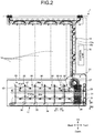
- FIG. 2 is a perspective side view illustrating a main part of the banknote storage apparatus 17 of the embodiment.
- FIG. 3A is a perspective side view illustrating the banknote storage apparatus 17 of the embodiment.
- FIG. 3B is a perspective plan view illustrating the banknote storage apparatus 17 of the embodiment.
- FIG. 3C is a perspective front view illustrating the banknote storage apparatus 17 of the embodiment.
- the banknote storage apparatus 17 of the embodiment is arranged at the bottom (bottom layer) of the banknote handling apparatus 1 so as to extend from the front side (the receipt/payment unit 11 side) of the banknote handling apparatus 1 toward the back side thereof, i.e., toward A1 and A2 directions being the depth direction of the banknote handling apparatus 1.
- the depth and height of the inner space of the banknote storage apparatus 17 can be sufficiently secured, and the workability, when the banknotes 5 stored in the inner space are collected, can be secured without any restriction due to the dimensions of the banknote handling apparatus 1 as compared with the case, where the banknote storage apparatus 17 is arranged in the front side or in the back side.
- the banknote storage apparatus 17 includes an alignment mechanism 21 as a carry-in mechanism that carries in banknotes 5, a storage mechanism 22 that has a plurality of storage spaces 35 in which the banknotes 5 are stored by the alignment mechanism 21, and a chassis 23 that supports the alignment mechanism 21 and the storage mechanism 22.
- the alignment mechanism 21 and the storage mechanism 22 are arranged inside the chassis 23.
- a carry-in port 24 through which the banknotes 5 conveyed by the conveying unit 15 are carried in, is provided in the upper side of the chassis 23.
- the alignment mechanism 21 and the storage mechanism 22 are controlled by the controller 16.
- the banknote storage apparatus 17 and the controller 16 are formed separately, but it may be configured so that the banknote storage apparatus 17 has the controller 16 or so that the banknote storage apparatus 17 itself has a control circuit for controlling the banknote storage apparatus 17 instead of the controller 16.
- the alignment mechanism 21 includes a carry-in roller 26 that carries in the banknotes 5 sent from the housing units 14 to the carry-in port 24, a pair of impellers 27 that convey the banknotes 5 carried in by the carry-in roller 26, and a placing table 28 on which the banknotes 5, conveyed by the pair of impellers 27, are stacked and placed.
- the alignment mechanism 21 also includes a lifting mechanism 31 that moves the placing table 28 up and down along B1 and B2 directions (see FIG. 3A ) with respect to the storage spaces 35 which is included in the storage mechanism 22.
- the alignment mechanism 21 is disposed to face one storage space 35 newly fed out by the storage mechanism 22, which is explained later.
- the alignment mechanism 21 carries the banknotes 5 in the storage spaces 35 in the order that the storage mechanism 22 feeds out the storage space 35.
- the carry-in roller 26 is provided near the carry-in port 24 of the chassis 23.
- the impeller 27 is supported by a rotating shaft 33 and is arranged rotatably in the C direction below the carry-in port 24.
- the pair of impellers 27 are arranged at a predetermined interval with respect to the axial direction of the rotating shaft 33 so as to correspond to the both sides in the long-side direction of the banknote 5, and are rotatably driven by a drive motor (not illustrated).
- the impeller 27 rotates while housing the banknote 5 carried in through the carry-in port 24 between adjacent blades, thereby conveying the banknotes downward.
- FIG. 4A is a side view illustrating the placing table 28 of the alignment mechanism 21 in the banknote storage apparatus 17 of the embodiment.
- FIG. 4B is a plan view illustrating the placing table 28 of the alignment mechanism 21 in the banknote storage apparatus 17 of the embodiment.
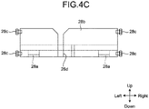
- FIG. 4C is a front view illustrating the placing table 28 of the alignment mechanism 21 in the banknote storage apparatus 17 of the embodiment.
- the placing table 28 is formed in a tray shape and has a pair of placing portions 28a on which both sides in the long-side direction of the banknote 5 are placed.
- Slide portions 28b which is supported by the side surface of the chassis 23, are respectively provided on the both sides of the placing table 28 in the D direction ( FIG. 3B ).
- Each of the slide portions 28b is provided with a guide shaft 28c, which is supported movably along the B1 and B2 directions on the side surface of the chassis 23.
- the slide portion 28b is provided with a connecting groove 28d, which is connected with the lifting mechanism 31.
- a lifting guide slit 23a for guiding the slide portion 28b of the placing table 28 is formed along the B1 and B2 directions, and the slide portion 28b of the placing table 28 is arranged movably along inside of the lifting guide slit 23a. Therefore, the placing table 28 is supported on the side surface of the chassis 23 with the placing portions 28a in a posture parallel to the horizontal direction.
- the lifting mechanism 31 includes a gear 31a driven by a drive motor (not illustrated), a pair of pulleys 31b rotated by the gear 31a, and a lifting belt 31c wound around the pair of pulleys 31b along the B1 and B2 directions.
- the lifting belt 31c is connected to the connecting groove 28d of the placing table 28 to move the placing table 28 with respect to the B1 and B2 directions.
- the conveying unit 15 conveys the banknote 5 with the short-side direction of the rectangular banknote 5 in parallel to the conveying direction. Therefore, the banknote 5, which is conveyed along the short-side direction of the banknote 5, is carried in through the carry-in port 24 from vertically upper side of the carry-in port 24, and the alignment mechanism 21 causes the banknotes 5, which is carried in from the carry-in port 24, to align on the placing table 28.
- the banknotes 5 aligned on the placing table 28 causes the long-side direction of the banknote 5 to be in parallel to the horizontal direction and to align in their stacked state along the A1 and A2 directions in the banknote storage apparatus 17.
- the alignment mechanism 21 can suppress the banknotes 5, which is carried into the banknote storage apparatus 17, from being disordered, and store the banknotes 5 properly in the storage space 35 provided in the storage mechanism 22.
- the alignment mechanism 21 causes the impellers 27 to rotate to thereby sequentially stack the banknotes 5 on the placing table 28 toward the A1 direction, so that the banknotes 5 are aligned on the placing table 28.
- the direction, in which the banknotes 5 are stacked in order on the placing table 28, is not limited to the order toward the A1 direction, and the banknotes 5 may be stacked in order toward the A2 direction.
- the placing table 28 is controlled by the controller 16 so that the height with respect to the carry-in port 24, i.e., the relative position to the impellers 27 is changed according to the external dimensions of the banknote 5, which is carried in through the carry-in port 24.
- the alignment mechanism 21 can properly place the banknotes 5 on the placing table 28, which makes it possible to suppress the occurrence of a jam that the banknotes 5 are clogged on the placing table 28.
- the alignment mechanism 21 includes a full sensor (not illustrated) for detecting that the placing table 28 is full of the banknotes 5 stacked on the placing table 28.
- a full sensor for detecting that the placing table 28 is full of the banknotes 5 stacked on the placing table 28.
- the full sensor for example, an optical sensor, which has a light emitting portion for emitting detection light and a light receiving portion for receiving detection light, is used.
- the full sensor detects that the placing table 28 is full of the banknotes 5 when the banknote 5, which is placed on the one end in the A1 direction of the placing table 28, blocks the detection light.
- the banknote handling apparatus 1 can detect that the placing table 28 is full of the banknotes 5 by causing, instead of using the full sensor, the controller 16 to count the number of banknotes 5 carried into the banknote storage apparatus 17 and to store the counted value in a semiconductor memory or the like. Then, when it is detected that the placing table 28 is full of the banknotes 5, the alignment mechanism 21 stores the banknotes 5 stacked on the placing table 28 in the storage space 35 of the storage mechanism 22.
- the storage mechanism 22 has a plurality of storage spaces 35 in which the banknotes 5 are stored, and continuously feeds out the storage spaces 35 toward the A1 direction, which is one direction, while forming the storage spaces 35 one by one.
- the storage mechanism 22 includes a plurality of partition members 36 for partitioning the storage spaces 35, and a link mechanism 37 for linking the partition members 36 so as to be tightly attached to each other in the A1 and A2 directions and for moving the partition members 36 in the A1 direction one by one.
- the storage mechanism 22 also includes a pair of drive belts 38 that drive the link mechanism 37 and that work as a placing member for placing thereon the banknotes 5, which are carried in the storage spaces 35.
- FIG. 5A is a side view illustrating the partition member 36 of the storage mechanism 22 in the banknote storage apparatus 17 of the embodiment.
- FIG. 5B is a plan view illustrating the partition member 36 of the storage mechanism 22 in the banknote storage apparatus 17 of the embodiment.
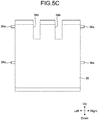
- FIG. 5C is a front view illustrating the partition member 36 of the storage mechanism 22 in the banknote storage apparatus 17 of the embodiment.
- the partition members 36 are formed in a plate shape so that they can be tightly attached to each other.
- One pair of upper and lower connecting shafts 36a connected to the link mechanism 37, are provided on the partition member 36 on both sides in the D direction along the shaft direction of the impeller 27.
- the partition member 36 is supported by the link mechanism 37 via the connecting shafts 36a in an upright posture in the vertical direction.
- slits 36b where the pair of impellers 27 are rotatably arranged are formed on the upper edge of the partition member 36.
- the adjacent partition members 36 are used as partition walls, which constitutes the storage space 35 in a space that the partition members 36 face each other by making a predetermined interval with respect to the A1 and A2 directions.
- the link mechanism 37 provided in the storage mechanism 22 includes a plurality of link members 41 connected in a zigzag manner, and a link actuating member 42 that moves the link members 41.
- the link members 41 are formed in a line shape, and end portions of a pair of adjacent link members 41 are rotatably connected via a guide shaft 41a.
- the other ends of both sides of the pair of link members 41, whose one ends are connected via the guide shaft 41a, are respectively connected to the connecting shafts 36a of the adjacent partition members 36. As illustrated in FIG.
- the link members 41 are alternately connected to the guide shaft 41a and the connecting shaft 36a of the partition member 36, and are configured so as to be extendable in the A1 and A2 directions. Two rows of the link members 41 connected in this manner are arranged on the upper and lower sides respectively on both sides in the D direction. Therefore, because the partition members 36 are fed out at given intervals in the A1 direction by each link member 41, the storage spaces 35 are equally created at the given intervals each between the adjacent partition members 36.
- a plurality of link guide slits 23b for guiding the guide shafts 41a each connecting the link members 41, are formed extending in the A1 and A2 directions on the side surface of the chassis 23, and the guide shaft 41a of the connected link members 41 is arranged movably along inside of the link guide slit 23b.
- the link guide slit 23b horizontally extends toward the A1 direction side and the end portion thereof on the A2 direction side is formed in a stepped shape that includes inclination with respect to the horizontal direction (A1 and A2 directions). For this reason, when the guide shaft 41a of the link members 41, connected to each other, moves in the A2 direction along the link guide slit 23b, the position of the guide shaft 41a changes in the B2 direction. As a result, each of the link members 41 is folded in an upright posture with respect to the vertical direction (B1 and B2 directions).
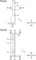
- FIG. 6A is a side view illustrating the link actuating member 42 of the storage mechanism 22 in the banknote storage apparatus 17 of the embodiment.
- FIG. 6B is a plan view illustrating the link actuating member 42 of the storage mechanism 22 in the banknote storage apparatus 17 of the embodiment.
- FIG. 6C is a front view illustrating the link actuating member 42 of the storage mechanism 22 in the banknote storage apparatus 17 of the embodiment.
- the link actuating member 42 is formed in a shape capable of being tightly attached to the partition member 36 in the A1 and A2 directions.
- One pair of upper and lower connecting shafts 42a connected to the other end portions of the link members 41, are provided on both sides of the link actuating member 42 in the D direction.
- the link actuating member 42 has a connecting portion 42b that is connected to the pair of drive belts 38, and the drive belts 38 are fixed to connecting grooves 42c that is formed on the connecting portion 42b.
- Slide portions 42d which are supported on the side surface of the chassis 23, are respectively provided on the both sides of the link actuating member 42 in the D direction ( FIG. 3B ).
- Each of the slide portions 42d is provided with guide shafts 42e that are supported movably along the A1 and A2 directions on the side surface of the chassis 23.
- a slide guide slit 23c for guiding the guide shafts 42e of the link actuating member 42 is formed on the side surface of the chassis 23 along the A1 and A2 directions, and the guide shafts 42e of the link actuating member 42, are arranged movably along inside of the slide guide slit 23c.
- the guide shafts 42e which are driven by the drive belts 38, move along the slide guide slit 23c, so that the link actuating member 42 moves with respect to the A1 and A2 directions.
- the link actuating member 42 moves in the A1 direction to thereby extend the connected link members 41 in the A1 direction and spread the link mechanism 37.
- the link mechanism 37 is spread to thereby feed out the partition members 36 one by one in the A1 direction together with the moving link members 41.
- the link mechanism 37 forms the storage spaces 35 one by one between the link actuating member 42 and the partition member 36 and between adjacent partition members 36.
- the link actuating member 42 moves in the A2 direction, thereby shrinking the connected link members 41 in the A2 direction and folding the link mechanism 37.
- the link mechanism 37 is folded to thereby cause the storage space 35 between the link actuating member 42 and the partition member 36 and between the adjacent storage spaces 35 to disappear.
- the link actuating member 42 functions also as a partition wall that constitutes the storage space 35 similarly to the partition member 36 in the head of the A1 direction (feeding-out direction).
- the pair of drive belts 38 are wound around a pair of pulleys 45a along the A1 and A2 directions.
- One of the pulleys 45a is rotated via a gear 45b that is driven by a drive motor (not illustrated).
- the pair of drive belts 38 are arranged at a predetermined interval L1 where both sides of the banknote 5 in the long-side direction are placed, and also function as placing members on which the banknotes 5, stored in the storage space 35, are placed.
- the interval L1 of the pair of drive belts 38 is made shorter than a length L0 in the long-side direction of the banknote 5, so that the both sides in the long-side direction of the banknote 5 can be placed on the drive belts 38.
- the storage mechanism 22 has a position sensor 47 as a detector that detects a position of the partition member 36.
- the position sensor 47 is arranged so as to face a position where the partition members 36 are fed out one by one by the link mechanism 37.
- an optical sensor which has a light emitting portion for emitting detection light toward the partition member 36 and a light receiving portion for receiving detection light emitted from the light emitting portion, is used.
- the position sensor 47 detects that the partition member 36 is in a predetermined position.
- FIG. 7A is a perspective side view illustrating a state in which the carried-in banknotes 5 are placed on the placing table 28 in the banknote storage apparatus of the embodiment.
- FIG. 7B is a perspective side view illustrating a state in which the placing table 28 on which the banknotes 5 are placed is moved down in the banknote storage apparatus 17 of the embodiment.
- FIG. 7C is a perspective side view illustrating a state in which the banknotes 5 placed on the placing table 28 are stored in the storage space 35 in the banknote storage apparatus 17 of the embodiment.
- FIG. 7D is a perspective side view illustrating a state in which the storage space 35 with the banknotes stored therein is fed and a next storage space 35 is fed out in the banknote storage apparatus 17 of the embodiment.
- FIG. 7A is a perspective side view illustrating a state in which the carried-in banknotes 5 are placed on the placing table 28 in the banknote storage apparatus of the embodiment.
- FIG. 7B is a perspective side view illustrating a state in which the
- FIG. 7E is a perspective side view illustrating a state in which the banknotes 5 are placed on the placing table 28 in the next storage space 35 in the banknote storage apparatus 17 of the embodiment.
- FIG. 7F is a perspective side view illustrating a state in which the banknotes 5 are stored respectively in the storage spaces 35 in the banknote storage apparatus 17 of the embodiment.
- FIG. 8 is a flowchart for explaining operations of the alignment mechanism 21 and the storage mechanism 22 in the banknote storage apparatus 17 of the embodiment.
- the banknote storage apparatus 17 moves the link actuating member 42 in the A1 direction by driving the drive belts 38 of the storage mechanism 22.
- the storage mechanism 22 creates the storage space 35 between the link actuating member 42, which is moved in the A1 direction, and the leading partition member 36 in the A1 direction.
- the placing table 28 of the alignment mechanism 21 is located inside the storage space 35, and the placing table 28 is moved up and down in the storage space 35 by the lifting mechanism 31 of the alignment mechanism 21.
- FIG. 7A is a diagram illustrating a state in which a first storage space 35 is opened and banknotes 5 are started to be fed into the storage space 35
- FIG. 7B is a diagram illustrating a state in which the banknotes 5 are staked in the storage space 35.
- the banknote storage apparatus 17 causes the lifting mechanism 31 of the alignment mechanism 21 to move up the placing table 28 in the B1 direction (Step S1 in FIG. 8 ).
- the controller 16 controls the alignment mechanism 21, so that the height in the B1 and B2 directions of the placing table 28 with respect to the carry-in port 24, becomes appropriate according to the external dimensions of the banknote 5, which is fed from the housing unit 14. Thereby, the placing table 28 is moved to the position where the banknotes 5 can be properly stacked.
- the banknote storage apparatus 17 causes the impellers 27 of the alignment mechanism 21 to rotate, and thereby conveys the banknotes 5, which are carried in from the carry-in port 24, and stacks the banknotes 5 on the placing portions 28a of the placing table 28 toward the A1 direction (Step S2 in FIG. 8 ).
- the alignment mechanism 21 continuously stacks the banknotes 5 on the placing table 28, and the controller 16 temporarily stops the rotation of the impellers 27 when the number of the banknotes 5, which are stacked on the placing table 28, reaches a predetermined number.
- the banknote storage apparatus 17 causes the lifting mechanism 31 of the alignment mechanism 21 to move down the placing table 28 in the B2 direction (Step S3 in FIG. 8 ).
- the banknote storage apparatus 17 moves the placing portions 28a of the placing table 28 to a position lower than the height of the drive belts 38 of the storage mechanism 22, thereby placing the banknotes 5, which are placed on the placing portions 28a, on the pair of drive belts 38.
- the banknote storage apparatus 17 carries the stacked banknotes 5 into the storage space 35 from the placing table 28, on which the banknote 5 are stacked, and stores the banknotes 5 in the storage space 35 (Step S4 in FIG. 8 ).
- the banknote storage apparatus 17 moves the link actuating member 42 in the A1 direction and feeds out the leading partition member 36 in the A1 direction via the link mechanism 37.
- the banknote storage apparatus 17 feeds the storage space 35 where the banknotes 5 are stored in the A1 direction, and moves the partition member 36, thereby feeding out the next storage space 35 (Step S5 in FIG. 8 ).
- the banknote storage apparatus 17 causes the lifting mechanism 31 of the alignment mechanism 21 to move up the placing table 28 in the B1 direction in the newly fed-out storage space 35 (Step S1), and stacks the banknotes 5 on the placing table 28 that is positioned at the appropriate height (Step S2). Thereafter, the banknote storage apparatus 17 causes the alignment mechanism 21 and the storage mechanism 22 to repeat the carry-in operation and the storing operation of the banknotes 5, thereby storing the banknotes 5 in the stacked state in the respective storage spaces 35 fed out in the A1 direction as illustrated in FIG. 7F and FIG. 8 . Then, the banknotes 5 stored in the storage spaces 35 are collected by a user from, for example, a collection port (not illustrated) that is openably/closably provided in the chassis 23.
- the storage spaces 35 to be fed out one by one in the A1 direction they are referred to as a first storage space 35, a second storage space 35, ⁇ an n-th storage space 35 sequentially from the A1 direction side.
- the partition members 36 to be fed out one by one in the A1 direction they are referred to as a first partition member 36, a second partition member 36, ⁇ an n-th partition member 36 sequentially from the A1 direction side.
- the first storage space 35 is created between the link actuating member 42 and the partition member 36 on the drive belts 38.
- the second storage space 35 is created between the first partition member 36 and the second partition member 36 on the drive belts 38.
- the third storage space 35 is created between the second partition member 36 and the third partition member 36 on the drive belts 38. Therefore, the n-th partition member 36 is created between the (n-1)-th partition member 36 and the n-th partition member 36 on the drive belts 38. In this way, the banknote storage apparatus 17 can feed out a plurality of storage spaces 35 one by one onto the drive belts 38 by the number of partition members 36 that is provided in the storage mechanism 22.
- the controller 16 controls each housing unit 14 so as to convey the banknotes 5 from the housing units 14 to the banknote storage apparatus 17, based on the denomination of the banknote 5, and it is thereby possible to store, for example, the banknotes 5 that are classified for each denomination in each storage space 35.
- the banknotes 5 of other denomination are stored in the second storage space 35.
- the banknote storage apparatus 17 may be configured so as to have a plurality types of storage spaces 35 with different sizes by setting different intervals between the partition members 36. According to this configuration, it is possible to store the banknotes 5 in a storage space 35 with an appropriate size corresponding to the dimensions of the denomination of the banknote 5, thus it is possible to stably store the plurality types of the banknotes 5 in the storage spaces 35.
- the banknote storage apparatus 17 folds the partition members 36 together with the link members 41, so that the storage spaces 35 are returned to the state that is ready to be fed out.
- the embodiment is not limited to such a storing operation.
- the controller 16 can also control so as to feed out arbitrarily the required number of storage spaces 35 according to the size of the inner space capable of feeding out the storage spaces 35 in the banknote storage apparatus 17. Therefore, for example, in a plurality of types of banknote handling apparatuses with different depth dimensions with respect to the A1 and A2 directions, it is possible to share the banknote storage apparatus 17 and it can be easily applied to the types of banknote handling apparatuses.
- the alignment mechanism 21 is configured so as to store the banknotes 5 sequentially from the first storage space 35 to the n-th storage space 35 at the position where the storage mechanism 22 feeds out the first storage space 35
- the embodiment is not limited to the positions of the impellers 27 and the placing table 28 with respect to the A1 and A2 directions.
- the alignment mechanism 21 may be configured so as to store the banknotes 5 sequentially from the first storage space 35 to the n-th storage space 35 at a position that faces the first storage space 35, which is fed in the A1 direction when the storage mechanism 22 feeds out the second storage space 35.
- the storage space 35 is continuously fed out in the A1 direction while creating a plurality of storage spaces 35 one by one and the banknotes 5 are carried into the storage spaces 35 in the order of feeding out the storage space 35.
- the banknotes 5 are stacked and the stacked banknotes 5 are carried into the storage space 35.
- the banknote storage apparatus 17 of the embodiment includes the storage mechanism 22 that continuously feeds out the storage spaces 35 in one direction while a plurality of storage spaces 35, which store the banknotes 5, are created one by one.
- the storage mechanism 22 plays a part of the function of carrying in the banknotes 5 by feeding the storage space 35 where the banknotes 5 are stored, so that it is possible to simplify the carry-in mechanism and a carry-in path for carrying the banknotes 5 into the storage spaces 35.
- the banknote storage apparatus 17 it is possible to reduce the space occupied by the carry-in mechanism and the carry-in path, to make effective use of the inner space in the banknote storage apparatus 17 as the storage spaces 35, and to efficiently store the banknotes 5 in the inner space.
- the banknote storage apparatus 17 of the embodiment includes the alignment mechanism 21 that carries the banknotes 5 in the storage spaces 35 in the order that the storage mechanism 22 feeds out the storage space 35, and the controller 16 that controls the alignment mechanism 21 and the storage mechanism 22. This makes it possible for the alignment mechanism 21 to appropriately carry the banknotes 5 in the respective storage spaces 35. Additionally, in the storing operation of the banknotes 5 in the storage space 35, because the carry-in operation of the banknotes 5 by the alignment mechanism 21, is simply stopped only when the storage mechanism 22 feeds out the storage space 35, it is possible to reduce the stop time of the storing operation and is possible to shorten the time required for storage.
- a single alignment mechanism 21 can carry the banknotes 5 in the plurality of storage spaces 35, the carry-in mechanism and the carry-in path can be simplified. Therefore, it is possible to make effective use of the inner space of the banknote storage apparatus 17 as the storage spaces 35 and is possible to efficiently store the banknotes 5 in the inner space.
- the storage mechanism 22 in the banknote storage apparatus 17 of the embodiment includes the plurality of partition members 36, the link mechanism 37 that moves the partition members 36 one by one in the A1 direction, and the drive belts 38 that places thereon the banknotes 5, which is carried in the storage spaces 35. Thereby, it is possible to simplify the configuration of the storage mechanism 22 for feeding out the storage spaces 35 and is possible to suppress the increase in driving force for driving the storage mechanism 22.
- the alignment mechanism 21 in the banknote storage apparatus 17 of the embodiment includes the impellers 27 that convey the banknotes 5, and the placing table 28 that stacks and places the banknotes 5, which are conveyed by the impellers 27.
- the alignment mechanism 21 in the banknote storage apparatus 17 of the embodiment includes the lifting mechanism 31 that moves the placing table 28 up and down with respect to the storage space 35, and the lifting mechanism 31 carries the banknotes 5 stacked on the placing table 28 into the storage space 35. Thereby, it is possible to appropriately and smoothly store the banknotes 5, which are carried in from the upper side in the vertical direction of the storage space 35 in the storage space 35. In addition, the banknotes 5, which are stacked on the placing table 28, can be carried into the storage space 35 in their stacked state.
- the controller 16 in the banknote handling apparatus 1 of the embodiment controls the storage mechanism 22 so as to feed out each of the storage spaces 35 to the same position with respect to the carry-in port 24 into which the banknote 5 is carried. Thereby, it is possible to keep the relative position between the carry-in port 24 and the storage space 35 constant, and the state, in which the banknotes 5 are carried into the storage space 35, becomes constant, so that the stability of the carry-in operation can be enhanced.
- the controller 16 in the banknote handling apparatus 1 of the embodiment controls the storage mechanism 22 so as to classify the plurality of types of banknotes 5 based on the types and store the classified banknotes 5 into the plurality of storage spaces 35. Thereby, it is possible to store the banknotes 5 that are classified for each denomination in the respective storage spaces 35.
- the storage mechanism 22 in the banknote storage apparatus 17 of the embodiment includes the position sensor 47 that detects the position of the partition member 36, which is moved by the link mechanism 37.
- the controller 16 controls the storage mechanism 22 so as to feed out the partition member 36 to a predetermined position based on the detection result of the position sensor 47. Thereby, it is possible to enhance the position accuracy of the storage spaces 35, which are fed out one by one by the storage mechanism 22, and is possible to more stably store the banknotes 5 in the storage spaces 35.
- the controller 16 in the banknote handling apparatus 1 of the embodiment controls the alignment mechanism 21 so as to change the position of the placing table 28 with respect to the impellers 27 according to the dimensions of a carried-in banknote 5. Thereby, it is possible to move the height of the placing table 28 to an appropriate position according to the dimensions of the banknote 5, which are carried by the impeller 27, and is possible to stably stack the banknotes 5 on the placing table 28.
- the banknote handling apparatus 1 of the embodiment can effectively utilize the space with respect to the depth direction (A1 and A2 directions) of the banknote handling apparatus 1 by arranging the banknote storage apparatus 17 at the bottom of the entire apparatus, so that it is possible to secure a large storage space 35 of the banknote storage apparatus 17.
- the banknotes 5 stored in the banknote handling apparatus 1 are to be collected, it is also possible to collect the banknotes 5 without hindering the banknote handling process of the banknote handling apparatus 1 and is possible to appropriately secure the workability when collecting the banknotes 5.
- the banknote storage apparatus 17 of the embodiment is configured so that the banknotes 5 on the placing table 28 or in the storage space 35 are stacked in the horizontal direction (A1 and A2 directions), the direction, in which the banknotes 5 are stacked, is not limited. It may also be configured so that the banknotes 5 are stacked on the placing table 28 or in the storage space 35 in the vertical direction (B1 and B2 directions).
- the banknote storage apparatus 17 of the embodiment is configured so that the alignment mechanism 21 has the lifting mechanism 31 that moves the placing table 28 up and down, the embodiment does not limit the configuration of the alignment mechanism 21.
- the banknote storage apparatus 17 may be configured so that the banknotes 5, which are conveyed by the impellers 27 of the alignment mechanism 21, are directly stored in the storage space 35.
- the banknote storage apparatus 17 of the embodiment is configured so that the banknotes 5 are carried in from the carry-in port 24 that is arranged vertically upward, the embodiment does not limit the carry-in direction of the banknotes 5.
- the embodiment may be configured so that the banknotes 5, which are carried in along the horizontal direction, are stacked on the placing table 28 by the impellers 27.
Landscapes
- Physics & Mathematics (AREA)
- General Physics & Mathematics (AREA)
- Engineering & Computer Science (AREA)
- Mechanical Engineering (AREA)
- Pile Receivers (AREA)
- Discharge By Other Means (AREA)
Abstract
Description
- The present invention relates to a paper sheet storage apparatus and a storing method of the paper sheet storage apparatus.
- Some banknote handling apparatuses used as, for example, an automated teller machine (ATM) include banknote storage apparatuses that store banknotes collected from the banknote handling apparatuses. This type of the banknote storage apparatus includes, for example, a carry-in mechanism for carrying in banknotes and a storage mechanism having a storage space that stores banknotes carried in by the carry-in mechanism.
- As a banknote storage apparatus of related art, a configuration is known in which the storage space for storing banknotes is divided into two spaces and the banknotes are stored by being pushed into the respective storage spaces by the storage mechanism.
- Patent Literature 1: International Publication Pamphlet No.
WO 2013/014698 - Incidentally, in order to efficiently collect the banknotes stored in the banknote storage apparatus, it is desirable to secure a large storage space for storing banknotes. When the large storage space is secured, the banknotes are sequentially stored from one end side to the other end side in one storage space. In this case, for example, a storage mechanism that pushes banknotes from one end side of the storage space into the storage space and that stores them, is used such as the banknote storage apparatus of related art. In such a storage mechanism, when a plurality of types of banknotes with different sizes are mixed and stored in the storage space, there is a possibility of occurrence of so-called jamming, in which the banknotes collide with each other and become clogged at the time of pushing the banknotes into the storage space.
- Therefore, a configuration is proposed in which the whole of the secured large storage space is divided to provide a plurality of storage spaces and banknotes are carried in each storage space. However, in the configuration that has a plurality of storage spaces, a carry-in mechanism, which includes carry-in paths for carrying banknotes into and storing them in the storage spaces, is provided in each storage space. For this reason, in the configuration using the storage spaces, a space occupied by the carry-in mechanism with respect to the inner space of the banknote storage apparatus is increased, and the inner space is not effectively used as the storage space, which makes it difficult to efficiently store the banknotes in the inner space.
- The disclosed technology has been made to solve the problems, and it is an object of the technology to provide a paper sheet storage apparatus and a storing method of the paper sheet storage apparatus capable of efficiently storing paper sheets in the inner space of the paper sheet storage apparatus.
- To solve the above problem and attain the object, a paper sheet storage apparatus disclosed in this application, according to an aspect, includes: a storage mechanism that includes a plurality of storage spaces where paper sheets are stored, and continuously feeds out the storage spaces toward one direction while creating the storage spaces one by one; a carry-in mechanism that carries the paper sheets into the storage spaces in the order that the storage mechanism feeds out the storage spaces; and a controller that controls the carry-in mechanism and the storage mechanism.
- According to one aspect of the paper sheet storage apparatus disclosed in the present application, paper sheets can be efficiently stored in the inner space of the paper sheet storage apparatus.
-
-
FIG. 1 is a schematic diagram illustrating the entire banknote handling apparatus including a banknote storage apparatus of an embodiment. -
FIG. 2 is a perspective side view illustrating a main part of the banknote handling apparatus of the embodiment. -
FIG. 3A is a perspective side view illustrating the banknote storage apparatus of the embodiment. -
FIG. 3B is a perspective plan view illustrating the banknote storage apparatus of the embodiment. -
FIG. 3C is a perspective front view illustrating the banknote storage apparatus of the embodiment. -
FIG. 4A is a side view illustrating a placing table of an alignment mechanism of the embodiment. -
FIG. 4B is a plan view illustrating the placing table of the alignment mechanism of the embodiment. -
FIG. 4C is a front view illustrating the placing table of the alignment mechanism of the embodiment. -
FIG. 5A is a side view illustrating a partition member of the storage mechanism of the embodiment. -
FIG. 5B is a plan view illustrating the partition member of the storage mechanism of the embodiment. -
FIG. 5C is a front view illustrating the partition member of the storage mechanism of the embodiment. -
FIG. 6A is a side view illustrating a link actuating member of the storage mechanism of the embodiment. -
FIG. 6B is a plan view illustrating the link actuating member of the storage mechanism of the embodiment. -
FIG. 6C is a front view illustrating the link actuating member of the storage mechanism of the embodiment. -
FIG. 7A is a perspective side view illustrating a state in which the carried-in banknotes are placed on the placing table in the banknote storage apparatus of the embodiment. -
FIG. 7B is a perspective side view illustrating a state in which the placing table on which the banknotes are placed is moved down in the banknote storage apparatus of the embodiment. -
FIG. 7C is a perspective side view illustrating a state in which the banknotes placed on the placing table are stored in the storage space in the banknote storage apparatus of the embodiment. -
FIG. 7D is a perspective side view illustrating a state in which the storage space with the banknotes stored therein is fed and a next storage space is fed out in the banknote storage apparatus of the embodiment. -
FIG. 7E is a perspective side view illustrating a state in which the banknotes are placed on the placing table in the next storage space in the banknote storage apparatus of the embodiment. -
FIG. 7F is a perspective side view illustrating a state in which the banknotes are stored in the respective storage spaces in the banknote storage apparatus of the embodiment. -
FIG. 8 is a flowchart for explaining operations of the alignment mechanism and the storage mechanism in the banknote storage apparatus of the embodiment. - Exemplary embodiments of the paper sheet storage apparatus and the storing method of the paper sheet storage apparatus disclosed in the present application, will be explained in detail below with reference to the accompanying drawings. It is to be noted that the embodiments below are not intended to limit the paper sheet storage apparatus and the storing method of the paper sheet storage apparatus disclosed in the present application. Embodiments
-
FIG. 1 is a schematic diagram illustrating the entire banknote handling apparatus including a banknote storage apparatus of an embodiment. In the figures afterFIG. 1 , the up-down direction, the front-back direction, and left-right direction of the banknote handling apparatus are indicated by arrows. As illustrated inFIG. 1 , abanknote handling apparatus 1 according to the embodiment includes a receipt/payment unit 11 that receives/paysbanknotes 5, and adistinction unit 12 that distinguishes thebanknotes 5 received from the receipt/payment unit 11. Thebanknote handling apparatus 1 also includes a holdingunit 13 that temporarily holds thebanknotes 5 conveyed from thedistinction unit 12, a plurality ofhousing units 14 that house thebanknotes 5 conveyed from the holdingunit 13, a conveyingunit 15 that conveys thebanknotes 5, and acontroller 16 that controls theunits 11 to 15. The conveyingunit 15 includes a plurality of conveyingrollers 15b (seeFIG. 2 ) arranged along a conveyingpath 15a of thebanknotes 5 and a drive mechanism (not illustrated) that drives the conveyingrollers 15b. - The
banknote handling apparatus 1 also includes astorage unit 17 that stores thebanknotes 5 sent from thehousing units 14 in order to collect thebanknotes 5 from thebanknote handling apparatus 1. Thestorage unit 17 incorporated in thebanknote handling apparatus 1, corresponds to the banknote storage apparatus of the embodiment and corresponds to a collection box that stores thebanknotes 5 collected from thebanknote handling apparatus 1. Hereinafter, thestorage unit 17 of thebanknote handling apparatus 1 will be explained as abanknote storage apparatus 17. Moreover, although thebanknotes 5 are used as an example of paper sheets in the present embodiment, the embodiment is not limited to thebanknotes 5, and, therefore, other paper sheets such as cash vouchers may be used. -
FIG. 2 is a perspective side view illustrating a main part of thebanknote storage apparatus 17 of the embodiment.FIG. 3A is a perspective side view illustrating thebanknote storage apparatus 17 of the embodiment.FIG. 3B is a perspective plan view illustrating thebanknote storage apparatus 17 of the embodiment.FIG. 3C is a perspective front view illustrating thebanknote storage apparatus 17 of the embodiment. - As illustrated in
FIG. 1 andFIG. 2 , thebanknote storage apparatus 17 of the embodiment is arranged at the bottom (bottom layer) of thebanknote handling apparatus 1 so as to extend from the front side (the receipt/payment unit 11 side) of thebanknote handling apparatus 1 toward the back side thereof, i.e., toward A1 and A2 directions being the depth direction of thebanknote handling apparatus 1. Thereby, the depth and height of the inner space of thebanknote storage apparatus 17 can be sufficiently secured, and the workability, when thebanknotes 5 stored in the inner space are collected, can be secured without any restriction due to the dimensions of thebanknote handling apparatus 1 as compared with the case, where thebanknote storage apparatus 17 is arranged in the front side or in the back side. - As illustrated in
FIG. 3A to FIG. 3C , thebanknote storage apparatus 17 includes analignment mechanism 21 as a carry-in mechanism that carries inbanknotes 5, astorage mechanism 22 that has a plurality ofstorage spaces 35 in which thebanknotes 5 are stored by thealignment mechanism 21, and achassis 23 that supports thealignment mechanism 21 and thestorage mechanism 22. Thealignment mechanism 21 and thestorage mechanism 22 are arranged inside thechassis 23. A carry-inport 24 through which thebanknotes 5 conveyed by the conveyingunit 15 are carried in, is provided in the upper side of thechassis 23. - The
alignment mechanism 21 and thestorage mechanism 22 are controlled by thecontroller 16. In the present embodiment, thebanknote storage apparatus 17 and thecontroller 16 are formed separately, but it may be configured so that thebanknote storage apparatus 17 has thecontroller 16 or so that thebanknote storage apparatus 17 itself has a control circuit for controlling thebanknote storage apparatus 17 instead of thecontroller 16. - The
alignment mechanism 21 includes a carry-inroller 26 that carries in thebanknotes 5 sent from thehousing units 14 to the carry-inport 24, a pair ofimpellers 27 that convey thebanknotes 5 carried in by the carry-inroller 26, and a placing table 28 on which thebanknotes 5, conveyed by the pair ofimpellers 27, are stacked and placed. Thealignment mechanism 21 also includes alifting mechanism 31 that moves the placing table 28 up and down along B1 and B2 directions (seeFIG. 3A ) with respect to thestorage spaces 35 which is included in thestorage mechanism 22. - As illustrated in
FIG. 3A , thealignment mechanism 21 is disposed to face onestorage space 35 newly fed out by thestorage mechanism 22, which is explained later. Thealignment mechanism 21 carries thebanknotes 5 in thestorage spaces 35 in the order that thestorage mechanism 22 feeds out thestorage space 35. - As illustrated in
FIG. 3A , the carry-inroller 26 is provided near the carry-inport 24 of thechassis 23. Theimpeller 27 is supported by a rotatingshaft 33 and is arranged rotatably in the C direction below the carry-inport 24. As illustrated inFIG. 3B andFIG. 3C , the pair ofimpellers 27 are arranged at a predetermined interval with respect to the axial direction of therotating shaft 33 so as to correspond to the both sides in the long-side direction of thebanknote 5, and are rotatably driven by a drive motor (not illustrated). Theimpeller 27 rotates while housing thebanknote 5 carried in through the carry-inport 24 between adjacent blades, thereby conveying the banknotes downward. -
FIG. 4A is a side view illustrating the placing table 28 of thealignment mechanism 21 in thebanknote storage apparatus 17 of the embodiment.FIG. 4B is a plan view illustrating the placing table 28 of thealignment mechanism 21 in thebanknote storage apparatus 17 of the embodiment.FIG. 4C is a front view illustrating the placing table 28 of thealignment mechanism 21 in thebanknote storage apparatus 17 of the embodiment. - As illustrated in
FIG. 3A to FIG. 3C andFIG. 4A to FIG. 4C , the placing table 28 is formed in a tray shape and has a pair of placingportions 28a on which both sides in the long-side direction of thebanknote 5 are placed.Slide portions 28b, which is supported by the side surface of thechassis 23, are respectively provided on the both sides of the placing table 28 in the D direction (FIG. 3B ). Each of theslide portions 28b is provided with aguide shaft 28c, which is supported movably along the B1 and B2 directions on the side surface of thechassis 23. As illustrated inFIG. 4B , theslide portion 28b is provided with a connectinggroove 28d, which is connected with thelifting mechanism 31. - On the other hand, as illustrated in
FIG. 3A , a lifting guide slit 23a for guiding theslide portion 28b of the placing table 28, is formed along the B1 and B2 directions, and theslide portion 28b of the placing table 28 is arranged movably along inside of the liftingguide slit 23a. Therefore, the placing table 28 is supported on the side surface of thechassis 23 with the placingportions 28a in a posture parallel to the horizontal direction. - As illustrated in
FIG. 3A to FIG. 3C , thelifting mechanism 31 includes agear 31a driven by a drive motor (not illustrated), a pair ofpulleys 31b rotated by thegear 31a, and a liftingbelt 31c wound around the pair ofpulleys 31b along the B1 and B2 directions. The liftingbelt 31c is connected to the connectinggroove 28d of the placing table 28 to move the placing table 28 with respect to the B1 and B2 directions. - The conveying
unit 15 according to the embodiment conveys thebanknote 5 with the short-side direction of therectangular banknote 5 in parallel to the conveying direction. Therefore, thebanknote 5, which is conveyed along the short-side direction of thebanknote 5, is carried in through the carry-inport 24 from vertically upper side of the carry-inport 24, and thealignment mechanism 21 causes thebanknotes 5, which is carried in from the carry-inport 24, to align on the placing table 28. Thebanknotes 5 aligned on the placing table 28 causes the long-side direction of thebanknote 5 to be in parallel to the horizontal direction and to align in their stacked state along the A1 and A2 directions in thebanknote storage apparatus 17. In this way, thealignment mechanism 21 can suppress thebanknotes 5, which is carried into thebanknote storage apparatus 17, from being disordered, and store thebanknotes 5 properly in thestorage space 35 provided in thestorage mechanism 22. - The
alignment mechanism 21 according to the present embodiment causes theimpellers 27 to rotate to thereby sequentially stack thebanknotes 5 on the placing table 28 toward the A1 direction, so that thebanknotes 5 are aligned on the placing table 28. The direction, in which thebanknotes 5 are stacked in order on the placing table 28, is not limited to the order toward the A1 direction, and thebanknotes 5 may be stacked in order toward the A2 direction. - The placing table 28 is controlled by the
controller 16 so that the height with respect to the carry-inport 24, i.e., the relative position to theimpellers 27 is changed according to the external dimensions of thebanknote 5, which is carried in through the carry-inport 24. Thus, thealignment mechanism 21 can properly place thebanknotes 5 on the placing table 28, which makes it possible to suppress the occurrence of a jam that thebanknotes 5 are clogged on the placing table 28. - The
alignment mechanism 21 includes a full sensor (not illustrated) for detecting that the placing table 28 is full of thebanknotes 5 stacked on the placing table 28. For example, when thebanknotes 5 are to be sequentially stacked on the placing table 28 toward the A1 direction, the full sensor is arranged on one end in the A1 direction of the placing table 28. As the full sensor, for example, an optical sensor, which has a light emitting portion for emitting detection light and a light receiving portion for receiving detection light, is used. The full sensor detects that the placing table 28 is full of thebanknotes 5 when thebanknote 5, which is placed on the one end in the A1 direction of the placing table 28, blocks the detection light. - The
banknote handling apparatus 1 can detect that the placing table 28 is full of thebanknotes 5 by causing, instead of using the full sensor, thecontroller 16 to count the number ofbanknotes 5 carried into thebanknote storage apparatus 17 and to store the counted value in a semiconductor memory or the like. Then, when it is detected that the placing table 28 is full of thebanknotes 5, thealignment mechanism 21 stores thebanknotes 5 stacked on the placing table 28 in thestorage space 35 of thestorage mechanism 22. - As illustrated in
FIG. 3A to 3C , thestorage mechanism 22 has a plurality ofstorage spaces 35 in which thebanknotes 5 are stored, and continuously feeds out thestorage spaces 35 toward the A1 direction, which is one direction, while forming thestorage spaces 35 one by one. Thestorage mechanism 22 includes a plurality ofpartition members 36 for partitioning thestorage spaces 35, and alink mechanism 37 for linking thepartition members 36 so as to be tightly attached to each other in the A1 and A2 directions and for moving thepartition members 36 in the A1 direction one by one. Thestorage mechanism 22 also includes a pair ofdrive belts 38 that drive thelink mechanism 37 and that work as a placing member for placing thereon thebanknotes 5, which are carried in thestorage spaces 35. -
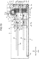
FIG. 5A is a side view illustrating thepartition member 36 of thestorage mechanism 22 in thebanknote storage apparatus 17 of the embodiment.FIG. 5B is a plan view illustrating thepartition member 36 of thestorage mechanism 22 in thebanknote storage apparatus 17 of the embodiment.FIG. 5C is a front view illustrating thepartition member 36 of thestorage mechanism 22 in thebanknote storage apparatus 17 of the embodiment. - As illustrated in
FIG. 3A to 3C andFIG. 5A to FIG. 5C , thepartition members 36 are formed in a plate shape so that they can be tightly attached to each other. One pair of upper and lower connectingshafts 36a connected to thelink mechanism 37, are provided on thepartition member 36 on both sides in the D direction along the shaft direction of theimpeller 27. As illustrated inFIG. 3A , thepartition member 36 is supported by thelink mechanism 37 via the connectingshafts 36a in an upright posture in the vertical direction. As illustrated inFIG. 3C and5C , slits 36b where the pair ofimpellers 27 are rotatably arranged, are formed on the upper edge of thepartition member 36. Theadjacent partition members 36 are used as partition walls, which constitutes thestorage space 35 in a space that thepartition members 36 face each other by making a predetermined interval with respect to the A1 and A2 directions. - As illustrated in
FIG. 3A andFIG. 3B , thelink mechanism 37 provided in thestorage mechanism 22, includes a plurality oflink members 41 connected in a zigzag manner, and alink actuating member 42 that moves thelink members 41. - The
link members 41 are formed in a line shape, and end portions of a pair ofadjacent link members 41 are rotatably connected via aguide shaft 41a. The other ends of both sides of the pair oflink members 41, whose one ends are connected via theguide shaft 41a, are respectively connected to the connectingshafts 36a of theadjacent partition members 36. As illustrated inFIG. 3A , in the pair oflink members 41 positioned at the head of the A1 direction side, the other end of the onelink member 41, one end of which is connected to theguide shaft 41a, is connected to the connectingshaft 36a of thepartition member 36, and the other end of theother link member 41, one end of which is connected to theguide shaft 41a, is connected to a connectingshaft 42a, explained later, provided in thelink actuating member 42. - Therefore, the
link members 41 are alternately connected to theguide shaft 41a and the connectingshaft 36a of thepartition member 36, and are configured so as to be extendable in the A1 and A2 directions. Two rows of thelink members 41 connected in this manner are arranged on the upper and lower sides respectively on both sides in the D direction. Therefore, because thepartition members 36 are fed out at given intervals in the A1 direction by eachlink member 41, thestorage spaces 35 are equally created at the given intervals each between theadjacent partition members 36. - A plurality of link guide slits 23b for guiding the
guide shafts 41a each connecting thelink members 41, are formed extending in the A1 and A2 directions on the side surface of thechassis 23, and theguide shaft 41a of theconnected link members 41 is arranged movably along inside of the link guide slit 23b. - The link guide slit 23b horizontally extends toward the A1 direction side and the end portion thereof on the A2 direction side is formed in a stepped shape that includes inclination with respect to the horizontal direction (A1 and A2 directions). For this reason, when the
guide shaft 41a of thelink members 41, connected to each other, moves in the A2 direction along the link guide slit 23b, the position of theguide shaft 41a changes in the B2 direction. As a result, each of thelink members 41 is folded in an upright posture with respect to the vertical direction (B1 and B2 directions). -
FIG. 6A is a side view illustrating thelink actuating member 42 of thestorage mechanism 22 in thebanknote storage apparatus 17 of the embodiment.FIG. 6B is a plan view illustrating thelink actuating member 42 of thestorage mechanism 22 in thebanknote storage apparatus 17 of the embodiment.FIG. 6C is a front view illustrating thelink actuating member 42 of thestorage mechanism 22 in thebanknote storage apparatus 17 of the embodiment. - As illustrated in
FIG. 3A ,FIG. 3B , andFIG. 6A toFIG. 6C , thelink actuating member 42 is formed in a shape capable of being tightly attached to thepartition member 36 in the A1 and A2 directions. One pair of upper and lower connectingshafts 42a connected to the other end portions of thelink members 41, are provided on both sides of thelink actuating member 42 in the D direction. Thelink actuating member 42 has a connectingportion 42b that is connected to the pair ofdrive belts 38, and thedrive belts 38 are fixed to connectinggrooves 42c that is formed on the connectingportion 42b. -
Slide portions 42d, which are supported on the side surface of thechassis 23, are respectively provided on the both sides of thelink actuating member 42 in the D direction (FIG. 3B ). Each of theslide portions 42d is provided withguide shafts 42e that are supported movably along the A1 and A2 directions on the side surface of thechassis 23. On the other hand, a slide guide slit 23c for guiding theguide shafts 42e of thelink actuating member 42, is formed on the side surface of thechassis 23 along the A1 and A2 directions, and theguide shafts 42e of thelink actuating member 42, are arranged movably along inside of the slide guide slit 23c. - The
guide shafts 42e, which are driven by thedrive belts 38, move along the slide guide slit 23c, so that thelink actuating member 42 moves with respect to the A1 and A2 directions. Thelink actuating member 42 moves in the A1 direction to thereby extend theconnected link members 41 in the A1 direction and spread thelink mechanism 37. Thelink mechanism 37 is spread to thereby feed out thepartition members 36 one by one in the A1 direction together with the movinglink members 41. As a result, thelink mechanism 37 forms thestorage spaces 35 one by one between thelink actuating member 42 and thepartition member 36 and betweenadjacent partition members 36. - On the other hand, the
link actuating member 42 moves in the A2 direction, thereby shrinking theconnected link members 41 in the A2 direction and folding thelink mechanism 37. Thelink mechanism 37 is folded to thereby cause thestorage space 35 between thelink actuating member 42 and thepartition member 36 and between theadjacent storage spaces 35 to disappear. In this way, thelink actuating member 42 functions also as a partition wall that constitutes thestorage space 35 similarly to thepartition member 36 in the head of the A1 direction (feeding-out direction). - The pair of
drive belts 38 are wound around a pair ofpulleys 45a along the A1 and A2 directions. One of thepulleys 45a is rotated via agear 45b that is driven by a drive motor (not illustrated). - In addition, as illustrated in
FIG. 3B , the pair ofdrive belts 38 are arranged at a predetermined interval L1 where both sides of thebanknote 5 in the long-side direction are placed, and also function as placing members on which thebanknotes 5, stored in thestorage space 35, are placed. The interval L1 of the pair ofdrive belts 38 is made shorter than a length L0 in the long-side direction of thebanknote 5, so that the both sides in the long-side direction of thebanknote 5 can be placed on thedrive belts 38. - As illustrated in
FIG. 3A andFIG. 3B , thestorage mechanism 22 has aposition sensor 47 as a detector that detects a position of thepartition member 36. Theposition sensor 47 is arranged so as to face a position where thepartition members 36 are fed out one by one by thelink mechanism 37. As theposition sensor 47, for example, an optical sensor, which has a light emitting portion for emitting detection light toward thepartition member 36 and a light receiving portion for receiving detection light emitted from the light emitting portion, is used. When thepartition member 36, fed out in the A1 direction, blocks the detection light, theposition sensor 47 detects that thepartition member 36 is in a predetermined position. - Regarding the
banknote storage apparatus 17 configured in the above manner, operations of thealignment mechanism 21 and thestorage mechanism 22 at the time of storing thebanknotes 5, will be explained with reference to the drawings. -
FIG. 7A is a perspective side view illustrating a state in which the carried-inbanknotes 5 are placed on the placing table 28 in the banknote storage apparatus of the embodiment.FIG. 7B is a perspective side view illustrating a state in which the placing table 28 on which thebanknotes 5 are placed is moved down in thebanknote storage apparatus 17 of the embodiment.FIG. 7C is a perspective side view illustrating a state in which thebanknotes 5 placed on the placing table 28 are stored in thestorage space 35 in thebanknote storage apparatus 17 of the embodiment.FIG. 7D is a perspective side view illustrating a state in which thestorage space 35 with the banknotes stored therein is fed and anext storage space 35 is fed out in thebanknote storage apparatus 17 of the embodiment.FIG. 7E is a perspective side view illustrating a state in which thebanknotes 5 are placed on the placing table 28 in thenext storage space 35 in thebanknote storage apparatus 17 of the embodiment.FIG. 7F is a perspective side view illustrating a state in which thebanknotes 5 are stored respectively in thestorage spaces 35 in thebanknote storage apparatus 17 of the embodiment.FIG. 8 is a flowchart for explaining operations of thealignment mechanism 21 and thestorage mechanism 22 in thebanknote storage apparatus 17 of the embodiment. - First of all, the
banknote storage apparatus 17 moves thelink actuating member 42 in the A1 direction by driving thedrive belts 38 of thestorage mechanism 22. Thestorage mechanism 22 creates thestorage space 35 between thelink actuating member 42, which is moved in the A1 direction, and the leadingpartition member 36 in the A1 direction. The placing table 28 of thealignment mechanism 21 is located inside thestorage space 35, and the placing table 28 is moved up and down in thestorage space 35 by thelifting mechanism 31 of thealignment mechanism 21. -
FIG. 7A is a diagram illustrating a state in which afirst storage space 35 is opened andbanknotes 5 are started to be fed into thestorage space 35, andFIG. 7B is a diagram illustrating a state in which thebanknotes 5 are staked in thestorage space 35. As illustrated inFIG. 7A ,FIG. 7B , andFIG. 8 , thebanknote storage apparatus 17 causes thelifting mechanism 31 of thealignment mechanism 21 to move up the placing table 28 in the B1 direction (Step S1 inFIG. 8 ). At this time, thecontroller 16 controls thealignment mechanism 21, so that the height in the B1 and B2 directions of the placing table 28 with respect to the carry-inport 24, becomes appropriate according to the external dimensions of thebanknote 5, which is fed from thehousing unit 14. Thereby, the placing table 28 is moved to the position where thebanknotes 5 can be properly stacked. - Subsequently, as illustrated in
FIG. 7A andFIG. 7B , thebanknote storage apparatus 17 causes theimpellers 27 of thealignment mechanism 21 to rotate, and thereby conveys thebanknotes 5, which are carried in from the carry-inport 24, and stacks thebanknotes 5 on the placingportions 28a of the placing table 28 toward the A1 direction (Step S2 inFIG. 8 ). In thebanknote storage apparatus 17, thealignment mechanism 21 continuously stacks thebanknotes 5 on the placing table 28, and thecontroller 16 temporarily stops the rotation of theimpellers 27 when the number of thebanknotes 5, which are stacked on the placing table 28, reaches a predetermined number. - Then, as illustrated in
FIG. 7C andFIG. 8 , thebanknote storage apparatus 17 causes thelifting mechanism 31 of thealignment mechanism 21 to move down the placing table 28 in the B2 direction (Step S3 inFIG. 8 ). At this time, thebanknote storage apparatus 17 moves the placingportions 28a of the placing table 28 to a position lower than the height of thedrive belts 38 of thestorage mechanism 22, thereby placing thebanknotes 5, which are placed on the placingportions 28a, on the pair ofdrive belts 38. As a result, thebanknote storage apparatus 17 carries thestacked banknotes 5 into thestorage space 35 from the placing table 28, on which thebanknote 5 are stacked, and stores thebanknotes 5 in the storage space 35 (Step S4 inFIG. 8 ). - Subsequently, as illustrated in
FIG. 7D andFIG. 8 , thebanknote storage apparatus 17 moves thelink actuating member 42 in the A1 direction and feeds out the leadingpartition member 36 in the A1 direction via thelink mechanism 37. As a result, thebanknote storage apparatus 17 feeds thestorage space 35 where thebanknotes 5 are stored in the A1 direction, and moves thepartition member 36, thereby feeding out the next storage space 35 (Step S5 inFIG. 8 ). - Thereafter, as illustrated in
FIG. 7E andFIG. 8 , thebanknote storage apparatus 17 causes thelifting mechanism 31 of thealignment mechanism 21 to move up the placing table 28 in the B1 direction in the newly fed-out storage space 35 (Step S1), and stacks thebanknotes 5 on the placing table 28 that is positioned at the appropriate height (Step S2). Thereafter, thebanknote storage apparatus 17 causes thealignment mechanism 21 and thestorage mechanism 22 to repeat the carry-in operation and the storing operation of thebanknotes 5, thereby storing thebanknotes 5 in the stacked state in therespective storage spaces 35 fed out in the A1 direction as illustrated inFIG. 7F andFIG. 8 . Then, thebanknotes 5 stored in thestorage spaces 35 are collected by a user from, for example, a collection port (not illustrated) that is openably/closably provided in thechassis 23. - Here, regarding the
storage spaces 35 to be fed out one by one in the A1 direction, they are referred to as afirst storage space 35, asecond storage space 35, ·· an n-th storage space 35 sequentially from the A1 direction side. Similarly, regarding thepartition members 36 to be fed out one by one in the A1 direction, they are referred to as afirst partition member 36, asecond partition member 36, ·· an n-th partition member 36 sequentially from the A1 direction side. - At this time, the
first storage space 35 is created between thelink actuating member 42 and thepartition member 36 on thedrive belts 38. Thesecond storage space 35 is created between thefirst partition member 36 and thesecond partition member 36 on thedrive belts 38. Thethird storage space 35 is created between thesecond partition member 36 and thethird partition member 36 on thedrive belts 38. Therefore, the n-th partition member 36 is created between the (n-1)-th partition member 36 and the n-th partition member 36 on thedrive belts 38. In this way, thebanknote storage apparatus 17 can feed out a plurality ofstorage spaces 35 one by one onto thedrive belts 38 by the number ofpartition members 36 that is provided in thestorage mechanism 22. - The
controller 16 controls eachhousing unit 14 so as to convey thebanknotes 5 from thehousing units 14 to thebanknote storage apparatus 17, based on the denomination of thebanknote 5, and it is thereby possible to store, for example, thebanknotes 5 that are classified for each denomination in eachstorage space 35. This allows thebanknote storage apparatus 17 to collect thebanknotes 5 that are classified for each denomination. In this case, for example, by conveying thebanknotes 5, which are classified for each denomination, from thehousing unit 14 to thebanknote storage apparatus 17, storing thebanknotes 5 of one denomination in thefirst storage space 35, and thereafter feeding out thesecond storage space 35, thebanknotes 5 of other denomination are stored in thesecond storage space 35. - When the
banknotes 5 are to be classified based on denominations and stored in thestorage spaces 35, thebanknote storage apparatus 17 may be configured so as to have a plurality types ofstorage spaces 35 with different sizes by setting different intervals between thepartition members 36. According to this configuration, it is possible to store thebanknotes 5 in astorage space 35 with an appropriate size corresponding to the dimensions of the denomination of thebanknote 5, thus it is possible to stably store the plurality types of thebanknotes 5 in thestorage spaces 35. - By moving the
link actuating member 42 in the A2 direction after thebanknotes 5 are collected from thestorage spaces 35, thebanknote storage apparatus 17 folds thepartition members 36 together with thelink members 41, so that thestorage spaces 35 are returned to the state that is ready to be fed out. - In the present embodiment, although all the
storage spaces 35 from thefirst storage space 35 to the n-th storage space 35, are fed out for use in the inner space of thebanknote storage apparatus 17, the embodiment is not limited to such a storing operation. In thebanknote storage apparatus 17, by folding thelink mechanism 37 and tightly attaching thepartition members 36 to each other, the state, where nostorage space 35, is created, i.e., the state, where thestorage space 35 is lost, is maintained. For this reason, thecontroller 16 can also control so as to feed out arbitrarily the required number ofstorage spaces 35 according to the size of the inner space capable of feeding out thestorage spaces 35 in thebanknote storage apparatus 17. Therefore, for example, in a plurality of types of banknote handling apparatuses with different depth dimensions with respect to the A1 and A2 directions, it is possible to share thebanknote storage apparatus 17 and it can be easily applied to the types of banknote handling apparatuses. - Although the
alignment mechanism 21 according to the present embodiment is configured so as to store thebanknotes 5 sequentially from thefirst storage space 35 to the n-th storage space 35 at the position where thestorage mechanism 22 feeds out thefirst storage space 35, the embodiment is not limited to the positions of theimpellers 27 and the placing table 28 with respect to the A1 and A2 directions. For example, thealignment mechanism 21 may be configured so as to store thebanknotes 5 sequentially from thefirst storage space 35 to the n-th storage space 35 at a position that faces thefirst storage space 35, which is fed in the A1 direction when thestorage mechanism 22 feeds out thesecond storage space 35. - In the storing method of the
banknote storage apparatus 17 configured as described above, thestorage space 35 is continuously fed out in the A1 direction while creating a plurality ofstorage spaces 35 one by one and thebanknotes 5 are carried into thestorage spaces 35 in the order of feeding out thestorage space 35. In the storing method of thebanknote storage apparatus 17, thebanknotes 5 are stacked and thestacked banknotes 5 are carried into thestorage space 35. - The
banknote storage apparatus 17 of the embodiment includes thestorage mechanism 22 that continuously feeds out thestorage spaces 35 in one direction while a plurality ofstorage spaces 35, which store thebanknotes 5, are created one by one. In thebanknote storage apparatus 17, when thestorage mechanism 22 feeds out thestorage spaces 35 one by one, thestorage mechanism 22 plays a part of the function of carrying in thebanknotes 5 by feeding thestorage space 35 where thebanknotes 5 are stored, so that it is possible to simplify the carry-in mechanism and a carry-in path for carrying thebanknotes 5 into thestorage spaces 35. As a result, in thebanknote storage apparatus 17, it is possible to reduce the space occupied by the carry-in mechanism and the carry-in path, to make effective use of the inner space in thebanknote storage apparatus 17 as thestorage spaces 35, and to efficiently store thebanknotes 5 in the inner space. - The
banknote storage apparatus 17 of the embodiment includes thealignment mechanism 21 that carries thebanknotes 5 in thestorage spaces 35 in the order that thestorage mechanism 22 feeds out thestorage space 35, and thecontroller 16 that controls thealignment mechanism 21 and thestorage mechanism 22. This makes it possible for thealignment mechanism 21 to appropriately carry thebanknotes 5 in therespective storage spaces 35. Additionally, in the storing operation of thebanknotes 5 in thestorage space 35, because the carry-in operation of thebanknotes 5 by thealignment mechanism 21, is simply stopped only when thestorage mechanism 22 feeds out thestorage space 35, it is possible to reduce the stop time of the storing operation and is possible to shorten the time required for storage. Moreover, because asingle alignment mechanism 21 can carry thebanknotes 5 in the plurality ofstorage spaces 35, the carry-in mechanism and the carry-in path can be simplified. Therefore, it is possible to make effective use of the inner space of thebanknote storage apparatus 17 as thestorage spaces 35 and is possible to efficiently store thebanknotes 5 in the inner space. - The
storage mechanism 22 in thebanknote storage apparatus 17 of the embodiment includes the plurality ofpartition members 36, thelink mechanism 37 that moves thepartition members 36 one by one in the A1 direction, and thedrive belts 38 that places thereon thebanknotes 5, which is carried in thestorage spaces 35. Thereby, it is possible to simplify the configuration of thestorage mechanism 22 for feeding out thestorage spaces 35 and is possible to suppress the increase in driving force for driving thestorage mechanism 22. - The
alignment mechanism 21 in thebanknote storage apparatus 17 of the embodiment includes theimpellers 27 that convey thebanknotes 5, and the placing table 28 that stacks and places thebanknotes 5, which are conveyed by theimpellers 27. By stacking thebanknotes 5 on the placing table 28 in this way, it is possible to suppress the occurrence of a jam that thebanknotes 5 are clogged when thebanknotes 5 are conveyed to thestorage spaces 35 and is possible to stably carry thebanknotes 5 into thestorage spaces 35. - The
alignment mechanism 21 in thebanknote storage apparatus 17 of the embodiment includes thelifting mechanism 31 that moves the placing table 28 up and down with respect to thestorage space 35, and thelifting mechanism 31 carries thebanknotes 5 stacked on the placing table 28 into thestorage space 35. Thereby, it is possible to appropriately and smoothly store thebanknotes 5, which are carried in from the upper side in the vertical direction of thestorage space 35 in thestorage space 35. In addition, thebanknotes 5, which are stacked on the placing table 28, can be carried into thestorage space 35 in their stacked state. - The
controller 16 in thebanknote handling apparatus 1 of the embodiment controls thestorage mechanism 22 so as to feed out each of thestorage spaces 35 to the same position with respect to the carry-inport 24 into which thebanknote 5 is carried. Thereby, it is possible to keep the relative position between the carry-inport 24 and thestorage space 35 constant, and the state, in which thebanknotes 5 are carried into thestorage space 35, becomes constant, so that the stability of the carry-in operation can be enhanced. - The
controller 16 in thebanknote handling apparatus 1 of the embodiment controls thestorage mechanism 22 so as to classify the plurality of types ofbanknotes 5 based on the types and store theclassified banknotes 5 into the plurality ofstorage spaces 35. Thereby, it is possible to store thebanknotes 5 that are classified for each denomination in therespective storage spaces 35. - The
storage mechanism 22 in thebanknote storage apparatus 17 of the embodiment includes theposition sensor 47 that detects the position of thepartition member 36, which is moved by thelink mechanism 37. Thecontroller 16 controls thestorage mechanism 22 so as to feed out thepartition member 36 to a predetermined position based on the detection result of theposition sensor 47. Thereby, it is possible to enhance the position accuracy of thestorage spaces 35, which are fed out one by one by thestorage mechanism 22, and is possible to more stably store thebanknotes 5 in thestorage spaces 35. - The
controller 16 in thebanknote handling apparatus 1 of the embodiment controls thealignment mechanism 21 so as to change the position of the placing table 28 with respect to theimpellers 27 according to the dimensions of a carried-inbanknote 5. Thereby, it is possible to move the height of the placing table 28 to an appropriate position according to the dimensions of thebanknote 5, which are carried by theimpeller 27, and is possible to stably stack thebanknotes 5 on the placing table 28. - The
banknote handling apparatus 1 of the embodiment can effectively utilize the space with respect to the depth direction (A1 and A2 directions) of thebanknote handling apparatus 1 by arranging thebanknote storage apparatus 17 at the bottom of the entire apparatus, so that it is possible to secure alarge storage space 35 of thebanknote storage apparatus 17. When thebanknotes 5 stored in thebanknote handling apparatus 1 are to be collected, it is also possible to collect thebanknotes 5 without hindering the banknote handling process of thebanknote handling apparatus 1 and is possible to appropriately secure the workability when collecting thebanknotes 5. - Although the
banknote storage apparatus 17 of the embodiment is configured so that thebanknotes 5 on the placing table 28 or in thestorage space 35 are stacked in the horizontal direction (A1 and A2 directions), the direction, in which thebanknotes 5 are stacked, is not limited. It may also be configured so that thebanknotes 5 are stacked on the placing table 28 or in thestorage space 35 in the vertical direction (B1 and B2 directions). - Although the
banknote storage apparatus 17 of the embodiment is configured so that thealignment mechanism 21 has thelifting mechanism 31 that moves the placing table 28 up and down, the embodiment does not limit the configuration of thealignment mechanism 21. Thebanknote storage apparatus 17 may be configured so that thebanknotes 5, which are conveyed by theimpellers 27 of thealignment mechanism 21, are directly stored in thestorage space 35. - Although the
banknote storage apparatus 17 of the embodiment is configured so that thebanknotes 5 are carried in from the carry-inport 24 that is arranged vertically upward, the embodiment does not limit the carry-in direction of thebanknotes 5. For example, it may be configured so that thebanknotes 5, which are carried in along the horizontal direction, are stacked on the placing table 28 by theimpellers 27. -
- 1
- BANKNOTE HANDLING APPARATUS
- 5
- BANKNOTE
- 16
- CONTROLLER
- 17
- BANKNOTE STORAGE APPARATUS (STORAGE UNIT)
- 21
- ALIGNMENT MECHANISM
- 22
- STORAGE MECHANISM
- 23
- CHASSIS
- 24
- CARRY-IN PORT
- 27
- IMPELLER
- 28
- PLACING TABLE
- 31
- LIFTING MECHANISM
- 35
- STORAGE SPACE
- 36
- PARTITION MEMBER
- 37
- LINK MECHANISM
- 38
- DRIVE BELT
- 41
- LINK MEMBER
- 42
- LINK ACTUATING MEMBER
- 47
- POSITION SENSOR
Claims (10)
- A paper sheet storage apparatus comprising:a storage mechanism that includes a plurality of storage spaces where paper sheets are stored, and continuously feeds out the storage spaces toward one direction while creating the storage spaces one by one;a carry-in mechanism that carries the paper sheets into the storage spaces in the order that the storage mechanism feeds out the storage spaces; anda controller that controls the carry-in mechanism and the storage mechanism.
- The paper sheet storage apparatus according to claim 1, wherein
the storage mechanism includes:a plurality of partition members that partition the storage spaces;a link mechanism that causes the partition members to connect each other so as to be tightly attached to each other in the one direction and that moves the partition members one by one in the one direction; anda placing member that places thereon the paper sheets carried in the storage spaces. - The paper sheet storage apparatus according to claim 2, wherein
the carry-in mechanism includes:an impeller that conveys the paper sheets; anda placing table that stacks and places thereon the paper sheets conveyed by the impeller. - The paper sheet storage apparatus according to claim 3, wherein
the carry-in mechanism includes a lifting mechanism that moves the placing table up and down with respect to the storage spaces, and
the lifting mechanism carries the paper sheets stacked on the placing table into the storage spaces. - The paper sheet storage apparatus according to claim 1, wherein
the controller controls the storage mechanism so as to feed out each of the storage spaces to a same position with respect to a carry-in port through which the paper sheets are carried in. - The paper sheet storage apparatus according to claim 1, wherein
the controller controls the storage mechanism so as to classify a plurality of types of paper sheets based on the types to store the classified paper sheets in the storage spaces. - The paper sheet storage apparatus according to claim 2, wherein
the storage mechanism includes a detector that detects a position of the partition member moved by the link mechanism, and
the controller controls the storage mechanism so as to feed out the partition member to a predetermined position based on the detection result of the detector. - The paper sheet storage apparatus according to claim 3, wherein
the controller controls the carry-in mechanism so as to change the position of the placing table with respect to the impeller according to dimensions of paper sheets to be carried in. - A storing method of a paper sheet storage apparatus comprising:continuously feeding out a plurality of storage spaces in one direction while creating the storage spaces one by one; andcarrying paper sheets into the storage spaces in order of feeding out the storage spaces.
- The storing method of a paper sheet storage apparatus according to claim 9, further comprising:stacking the paper sheets; andcarrying the stacked paper sheets into the storage spaces.
Applications Claiming Priority (1)
| Application Number | Priority Date | Filing Date | Title |
|---|---|---|---|
| PCT/JP2015/080414 WO2017072881A1 (en) | 2015-10-28 | 2015-10-28 | Postcards storing device and storing method of postcards storing device |
Publications (2)
| Publication Number | Publication Date |
|---|---|
| EP3370210A1 true EP3370210A1 (en) | 2018-09-05 |
| EP3370210A4 EP3370210A4 (en) | 2018-11-07 |
Family
ID=58631390
Family Applications (1)
| Application Number | Title | Priority Date | Filing Date |
|---|---|---|---|
| EP15907245.3A Withdrawn EP3370210A4 (en) | 2015-10-28 | 2015-10-28 | Postcards storing device and storing method of postcards storing device |
Country Status (5)
| Country | Link |
|---|---|
| US (1) | US10297098B2 (en) |
| EP (1) | EP3370210A4 (en) |
| JP (1) | JP6534748B2 (en) |
| CN (1) | CN108140272A (en) |
| WO (1) | WO2017072881A1 (en) |
Families Citing this family (2)
| Publication number | Priority date | Publication date | Assignee | Title |
|---|---|---|---|---|
| WO2021152666A1 (en) * | 2020-01-27 | 2021-08-05 | 富士通フロンテック株式会社 | Paper sheet storing device and paper sheet handling device |
| DE102021001544A1 (en) * | 2021-03-24 | 2022-09-29 | Giesecke+Devrient Currency Technology Gmbh | Method for producing an electrode stack and stacking device |
Family Cites Families (15)
| Publication number | Priority date | Publication date | Assignee | Title |
|---|---|---|---|---|
| US3236162A (en) * | 1964-02-07 | 1966-02-22 | Ferag Fehr & Reist A G | Delivery apparatus for the products of a rotary press |
| JPS5151395A (en) * | 1974-10-30 | 1976-05-06 | Laurel Bank Machine Co | Shiheiruino toriatsukaisochi |
| JPS61291363A (en) * | 1985-06-17 | 1986-12-22 | Toshiba Corp | Paper sheets processing device |
| DE4008973C1 (en) * | 1990-03-20 | 1991-07-25 | Siemens Nixdorf Informationssysteme Ag, 4790 Paderborn, De | |
| US5735519A (en) * | 1995-02-09 | 1998-04-07 | Fuji Photo Film Co., Ltd. | Photosensitive-material conveying apparatus |
| US5745519A (en) * | 1996-11-12 | 1998-04-28 | Opto Power Corp. | Laser diode system |
| JP2002321862A (en) * | 2001-04-27 | 2002-11-08 | Oki Electric Ind Co Ltd | Paper sheet delivering accumulating device |
| JP2005010967A (en) | 2003-06-18 | 2005-01-13 | Hitachi Ltd | Banknote deposit and withdrawal device and automatic cash transaction device |
| JP2005145596A (en) * | 2003-11-13 | 2005-06-09 | Noritsu Koki Co Ltd | Image processing sheet material sorting apparatus of image processing apparatus |
| JP2006350921A (en) * | 2005-06-20 | 2006-12-28 | Toshiba Corp | Paper sheet processing equipment |
| JP2007290850A (en) * | 2006-04-27 | 2007-11-08 | Hitachi Omron Terminal Solutions Corp | Paper sheet stacking and feeding device |
| JP2011054058A (en) * | 2009-09-03 | 2011-03-17 | Oki Electric Industry Co Ltd | Paper sheet storage |
| WO2013014698A1 (en) | 2011-07-22 | 2013-01-31 | 日立オムロンターミナルソリューションズ株式会社 | Paper processing device and paper storage device |
| JP2014109797A (en) | 2012-11-30 | 2014-06-12 | Glory Ltd | Paper money processing unit |
| KR101671572B1 (en) * | 2014-06-20 | 2016-11-01 | 주식회사 엘지씨엔에스 | Medium storage apparatus and method, financial device |
-
2015
- 2015-10-28 JP JP2017547253A patent/JP6534748B2/en active Active
- 2015-10-28 EP EP15907245.3A patent/EP3370210A4/en not_active Withdrawn
- 2015-10-28 CN CN201580084018.7A patent/CN108140272A/en active Pending
- 2015-10-28 WO PCT/JP2015/080414 patent/WO2017072881A1/en not_active Ceased
-
2018
- 2018-04-02 US US15/943,174 patent/US10297098B2/en active Active
Also Published As
| Publication number | Publication date |
|---|---|
| JP6534748B2 (en) | 2019-06-26 |
| US20180225903A1 (en) | 2018-08-09 |
| JPWO2017072881A1 (en) | 2018-02-08 |
| US10297098B2 (en) | 2019-05-21 |
| CN108140272A (en) | 2018-06-08 |
| WO2017072881A1 (en) | 2017-05-04 |
| EP3370210A4 (en) | 2018-11-07 |
Similar Documents
| Publication | Publication Date | Title |
|---|---|---|
| JP5274999B2 (en) | Banknote handling equipment | |
| US9947182B2 (en) | Medium processing device and medium transaction device | |
| JP6165652B2 (en) | Paper sheet loading / unloading device | |
| JP5632092B2 (en) | Paper sheet handling device transport mechanism | |
| US10297098B2 (en) | Paper sheet storage apparatus and storing method of paper sheet storage apparatus | |
| JP6197615B2 (en) | Coin storage, coin storage control method, and coin processing apparatus | |
| JP6259725B2 (en) | Paper sheet separating and accumulating equipment | |
| JP6361112B2 (en) | Paper sheet handling equipment | |
| JP4549899B2 (en) | Small bundle banknote processing machine | |
| JP4549897B2 (en) | Small bundle banknote processing machine | |
| JP4302651B2 (en) | Small bundle banknote processing machine | |
| JP4663380B2 (en) | Small bundle banknote processing machine | |
| JP4549896B2 (en) | Small bundle banknote processing machine | |
| JP4549895B2 (en) | Small bundle banknote processing machine | |
| JP4302652B2 (en) | Small bundle banknote processing machine | |
| JP2011054058A (en) | Paper sheet storage | |
| JP4593322B2 (en) | Small bundle banknote processing machine | |
| JP4549892B2 (en) | Small bundle banknote processing machine | |
| KR101662901B1 (en) | Medium handling apparatus and financial device | |
| JP6206170B2 (en) | Small bundle processing equipment | |
| JP4606909B2 (en) | Small bundle banknote processing machine | |
| JP4549894B2 (en) | Small bundle banknote processing machine | |
| JP4549893B2 (en) | Small bundle banknote processing machine |
Legal Events
| Date | Code | Title | Description |
|---|---|---|---|
| STAA | Information on the status of an ep patent application or granted ep patent |
Free format text: STATUS: THE INTERNATIONAL PUBLICATION HAS BEEN MADE |
|
| PUAI | Public reference made under article 153(3) epc to a published international application that has entered the european phase |
Free format text: ORIGINAL CODE: 0009012 |
|
| STAA | Information on the status of an ep patent application or granted ep patent |
Free format text: STATUS: REQUEST FOR EXAMINATION WAS MADE |
|
| 17P | Request for examination filed |
Effective date: 20180328 |
|
| AK | Designated contracting states |
Kind code of ref document: A1 Designated state(s): AL AT BE BG CH CY CZ DE DK EE ES FI FR GB GR HR HU IE IS IT LI LT LU LV MC MK MT NL NO PL PT RO RS SE SI SK SM TR |
|
| AX | Request for extension of the european patent |
Extension state: BA ME |
|
| A4 | Supplementary search report drawn up and despatched |
Effective date: 20181009 |
|
| RIC1 | Information provided on ipc code assigned before grant |
Ipc: B65H 31/30 20060101ALI20181003BHEP Ipc: B65H 31/10 20060101ALI20181003BHEP Ipc: B65H 39/043 20060101ALI20181003BHEP Ipc: B65H 39/115 20060101ALI20181003BHEP Ipc: G07D 11/00 20060101ALI20181003BHEP Ipc: B65H 43/00 20060101ALI20181003BHEP Ipc: B65H 29/40 20060101AFI20181003BHEP |
|
| DAV | Request for validation of the european patent (deleted) | ||
| DAX | Request for extension of the european patent (deleted) | ||
| STAA | Information on the status of an ep patent application or granted ep patent |
Free format text: STATUS: THE APPLICATION IS DEEMED TO BE WITHDRAWN |
|
| 18D | Application deemed to be withdrawn |
Effective date: 20190507 |