EP3370124A1 - Garantie de la conformité d'interface dans un système de commande de processus modulaire - Google Patents
Garantie de la conformité d'interface dans un système de commande de processus modulaire Download PDFInfo
- Publication number
- EP3370124A1 EP3370124A1 EP17158738.9A EP17158738A EP3370124A1 EP 3370124 A1 EP3370124 A1 EP 3370124A1 EP 17158738 A EP17158738 A EP 17158738A EP 3370124 A1 EP3370124 A1 EP 3370124A1
- Authority
- EP
- European Patent Office
- Prior art keywords
- control
- target system
- interface
- user
- function
- Prior art date
- Legal status (The legal status is an assumption and is not a legal conclusion. Google has not performed a legal analysis and makes no representation as to the accuracy of the status listed.)
- Withdrawn
Links
Images


Classifications
-
- G—PHYSICS
- G05—CONTROLLING; REGULATING
- G05B—CONTROL OR REGULATING SYSTEMS IN GENERAL; FUNCTIONAL ELEMENTS OF SUCH SYSTEMS; MONITORING OR TESTING ARRANGEMENTS FOR SUCH SYSTEMS OR ELEMENTS
- G05B19/00—Programme-control systems
- G05B19/02—Programme-control systems electric
- G05B19/04—Programme control other than numerical control, i.e. in sequence controllers or logic controllers
- G05B19/042—Programme control other than numerical control, i.e. in sequence controllers or logic controllers using digital processors
- G05B19/0423—Input/output
-
- G—PHYSICS
- G05—CONTROLLING; REGULATING
- G05B—CONTROL OR REGULATING SYSTEMS IN GENERAL; FUNCTIONAL ELEMENTS OF SUCH SYSTEMS; MONITORING OR TESTING ARRANGEMENTS FOR SUCH SYSTEMS OR ELEMENTS
- G05B2219/00—Program-control systems
- G05B2219/30—Nc systems
- G05B2219/31—From computer integrated manufacturing till monitoring
- G05B2219/31113—General, vendor indenpendant display and control interface for sensor actuator
Definitions
- the present invention generally relates to process control systems. More particularly the present invention relates to an interface conformity ensuring device for a process control system as well as to a method and a computer program product for ensuring interface conformity of a process control module to be provided for controlling a process control system section.
- a process control system may be provided in an industrial plant. Such a system may comprise a number of process control modules, where each process control module is concerned with the control of a section of the process control system.
- Every module has its own automation system (maybe from different vendors) but describes the interfaces to control the automation system from a process control system that is laying on top of the various modules. These interfaces are at the moment standardized in the German community and will be standardized as an IEC standard. In order to have a seamless integration of the modules, every module has to comply with the standard interfaces and thus has to ensure that the interfaces are in conformance with the standard.
- Creating the visualization for the process is basically painting a picture, but for the interfaces the connections between the graphical object, e.g. a pipe and a valve is required. This information is hard to obtain from the engineering tools of the controller. Another problem is that the module vendors need to learn every engineering tool just to create the visualization and the module interfaces.
- a middleware would be of advantage, as well, since the module vendors could simply describe the predecessor-successor relationship of the equipment, without having to fully describe the visualization that is later anyway imported and changed in the overlaying process control system.
- a middleware that is easy to use, only provides the necessary feature for the module engineer and that ensures interface compliance may be required.
- US 2016/0224001 does for instance disclose a method for facilitating use of function blocks for first applications complying to a first standard in second applications complying with a second standard.
- the first function block has a first interface and is created by use of a first tool compliant with a first standard.
- a platform independent model (PIM) for the second application with a second tool compliant with the second standard, which second function block comprises the first interface and an event interface.
- PIM platform independent model
- the present invention addresses the problem of providing a middleware that ensures interface conformity between modules and overall control.
- this object is more particularly achieved through an interface conformity ensuring device for a process control system that is to comprise different modules for controlling different process control system sections, the interface conformity ensuring device being configured to:
- This object is according to a second aspect of the invention achieved through a method for ensuring interface conformity of a process control module to be provided for controlling a process control system section.
- the method is performed by interface conformity ensuring device and comprises:
- This object is according to a third aspect of the invention solved through a computer program product for ensuring interface conformity of a process control module to be provided for controlling a process control system section.
- the computer program product is provided on a data carrier comprising computer program code configured to cause a interface conformity ensuring device to, when the computer program code is loaded into the interface conformity ensuring device:
- the present invention has a number of advantages. It provides a middleware that is easy to use, only provides the necessary feature for the user and that ensures interface compliance.
- Fig. 1 schematically shows a process control system 10, which may be provided in the premises of an industrial plant.
- the process control system 10 is a computerized process control system for controlling an industrial process.
- industrial processes that may be controlled are electrical power generation, transmission and distribution processes, water purification and distribution processes, oil and gas production and distribution processes, petrochemical, chemical, pharmaceutical and food processes, and pulp and paper production processes. These are just some examples of processes where the system can be applied. There exist countless other industrial processes.
- the processes may also be other types of industrial processes such as the manufacturing of goods.
- a process may be monitored through one or more process monitoring computers, which communicate with a computer or server handling monitoring and control of the process.
- the process control system 10 therefore includes a number of process monitoring computers (PMC) 12 and 14. These computers may here also be considered to form operator terminals and are connected to a first data bus DB. There is also a process control computer PCC 18 and a database (DB) 16 connected to the first data bus DB. To this first data bus DB there is also connected a first, second and third local process control device (PCD) 20, 28 and 36.
- a local process control device PCD may be a device, such as a controller, that is responsible to perform local control, such as control in a module of the control system 10.
- the process control computer 18 may in this case be responsible for overall control of the process, where the process control devices 20, 28 and 36 are responsible for local control in the respective section.
- Each local process control device PCD is thus connected to a corresponding group of field devices via a field bus FB.
- first section S1 in whihc the first local process control device 20 is connected to a first group of field devices 22, 24 and 26 via a first field bus FB1.
- second section S2 in which the second local process control device 28 is connected to a second group of field devices 30, 32 and 34 via a second field bus FB2.
- third section S3 in which the third local process control device 36 is connected to a third group of field devices 30, 32 and 34 via a third field bus FB2.
- a field device is physical n interface to a process being controlled.
- a field device is therefore an interface, such as a sensor, via which measurements of the process are being made or an interface, such as an actuator, to which control commands are given for influencing the process.
- a field device may also be a combined sensor and actuator.
- a field device may as an example be a tank and another as an example a valve.
- the local process control devices 20, 28 and 38 may be involved in controlling the process in the corresponding section based on inputs from field devices, such as from sensors, and actuating the same or other field devices, such as valves based on the inputs.
- the process control computer 18 may in turn be involved in control of the different modules.
- the control functionality performed by the local process control devices may in fact also be provided in the process control computer.
- control functionality for such a section may be provided through a process control module.
- An engineering terminal may be a stand-alone computer that is used to generate computer program code that implements the process control functionality and this code will then implement the functionality when being implemented on a local process control device or the process control computer.
- One engineering terminal used to provide a middleware in relation to a target system engineering terminal may according to aspects of the invention be an interface conformity ensuring device.
- a target system engineering terminal may be an engineering terminal on which a target system, which may be the control system of one of the process control modules, is set up.
- the interface conformity ensuring device ICED 44 may be realized as a computer comprising a processor (PR) 46 with program memory (PM) 48 comprising a computer program 50 with computer program code implementing the functionality of the interface conformity ensuring device 44.
- the interface conformity ensuring device 44 may also comprise a user interface (UI) 52 for instance in the form of a display and mouse/keyboard combination.
- UI user interface
- the interface conformity ensuring device 44 may comprise a process function obtaining unit PFO 54, a process structure obtaining unit PSO 56, a system communication structure unit 58, a communication interfaces generating unit CIG 60, a state machine generating unit SMG 62, an equipment control block generating unit ECBG 64 and an interface description generating unit IDG 66 in addition to the user interface (UI) 52. It is here possible that these units 54 - 55 are provided through software code in a computer program memory together with a processor for running this code. As an alternative the units may be provided in the form of one or more dedicated circuits such as such as Field-Programmable Gate Arrays (FPGAs) or Application Specific Integrated Circuits (ASICs).
- FPGAs Field-Programmable Gate Arrays
- ASICs Application Specific Integrated Circuits
- the overall process control computer 18 is supplied by one of the above-mentioned or a further supplier. It is thereby also possible that the computer program implementing the control functionality may differ between modules implementing the control functionality of the sections as well as between a module and the overall control.
- the computer program code used for implementing the functionalities of the different modules may be proprietary. Therefore, it is necessary that the module code has interfaces according to a defined communication standard with which the other modules that implement the control code for the other sections and the overall all control functionality can communicate with the first module. Moreover a module may also need a description in a standardised format that describes the control functionality.
- the interface conformity ensuring device 44 provides a middleware that is used to describe target system independent interfaces of a module.
- the module that is provided by the interface conformity ensuring device 44 thereby comprises computer code defining the control functions and process structure of the process control system in a corresponding process control section. This module is thereby also an automation system module.
- the interface conformity ensuring device 44 automatically generates target system dependent interfaces, communication and parts of the control code, where the generation of the target system dependent interfaces may be the system interfaces of the proprietary software used to build the module control functionality and process structure and.
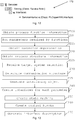
- the method may start with the process function obtaining unit 54 obtaining from a user via the user interface 52, information about the process functions required in the process module, step 200.
- the user which may be a system engineer, may define which process functions are required within the module. These might be for example mixing, tempering or inertization of the module.
- the user thus provides process function information PFI 70, which may be done in a process function definition area shown in fig. 8 .
- function definitions may, as is shown in fig. 4 , be made through the user opening a folder Services and there place a number of functions, where each such function is a selected a function that is to be used by the module.
- the user may here select a function and give it a number and a name.
- parameters required by the functions are added, step 210.
- Two parameters may be automatically added by the process function obtaining unit 54 as a Control parameter and a Status parameter.
- Each process may thus be provided with these parameters by the function obtaining unit 54, triggered by the user selecting the functions. All required process functions may then simply be added to the folder and do not need any more configuration.
- Control is an input to the function and the parameter Status is an output generated as a response to the parameter Control.
- the parameters being added may also comprise parameters being added by the user.
- the user may thus add, under the control of the process function obtaining unit 54, any parameters that are required by the various process functions. Besides the process functions, the required parameters are thus added by the user.
- the temperature may be needed to be used in the process control during runtime. Therefore a service parameter may need to be exposed by the module. This is in fig. 4 shown by the Tempering function receiving the parameter Temperature.
- the process function obtaining unit 54 obtains dependencies between the process function parameters, step 215. It is thus possible that the process functions of the module have to be interlocked, i.e. not be allowed to occupy certain states simultaneously, so that the states may need to be defined as mutually exclusive. For instance, if there is a heating function and a cooling function for the module, those may not be allowed to run at the same time.
- the user or engineer can describe the interlock using function block diagrams, for instance using IEC 61131-3 or some similar functions to assure that these services are not executed at the same time. This may be done in the process function definition area shown in the left side of fig. 8 . As is schematically shown in fig.
- the process structure obtaining unit 56 may obtain, from the user via the user interface 54 in a process structure definition area, see the left side of fig. 8 , process structure information, step 220.
- the obtaining of the process structure may comprise receiving from the user, a selection of process structure elements such as machines to be involved in the control.
- the process structure of the module may be defined by the user in the form of process graphics. The user may in this case insert, for every piece of equipment that is to be used by the module, a symbol in a process structure definition part 100 of the middleware. The symbols may be connected, which is shown in fig. 6 , with simple lines and thereby, the process structure is defined.
- the module is shown as comprising two valves leading into a tank, in which tank there is a mixer operated by a motor. There is also a pipe leaving the tank comprising a further valve.
- the inserted objects may, by the process s structure forming unit 56 and based on the objects interconnected by the user, be placed in a tree structure of Human Machine Interface (HMI) objects in the view. Every used piece of equipment may get a tag name. If the user wants to describe e.g. different levels of detail in the process structure, those may be added as new objects in the tree and the same procedure can be applied.
- HMI Human Machine Interface
- the interface conformity ensuring device may receive, a selection of a target system from the user, via the user interface, step 225.
- the target system may in this case be the control system of a particular vendor that is to be implemented in the module.
- the target system may thus be a proprietary control device or controller to be used for implementing the control functionality of the module.
- the vendor may also have a number of machines dedicated to the type of functionality provided by the above-defined types of functions.
- the system communication structure unit 58 may determine a target system dependent communication structure, step 230. This may involve generating process function communication definitions FCD 110, for instance in the form of computer objects, based on the process function information 7oand generating process structure communication definitions PSCD 120 based on the process structure definitions 100, see fig. 7 and 8 . For every process function and the used process function parameters, a communication object that aims on the corresponding target system dependent variables and structure may be created. In fig. 7 it can be seen that communication object Run, Inertization and Tempering are created together with a number of further objects associated with other functions, all of which are specific to the selected target system, which may be the system of a certain vendor. The user only has to select the target system and the communication structure is automatically defined. Also the variables are defined in the communication structure, something that is shown for the Tempering function.
- a communication object is created in the process structure communication definition 120, as well.
- the communication interface generating unit selects a corresponding piece of equipment or machine of the selected vendor.
- corresponding communication variables associated with the machine may also be automatically created in the communication structure as variables that correspond to the target automation system variable.
- the communication interface generating unit 58 generates at least one interfacing object that provides the target systems interface code of the target system, step 235, i.e. the computer code that is used for interacting with the other modules and overall control module of the process control system.
- the interface code is generated through an interface code object 122.
- the target system has to provide the required interfaces in order to be seamlessly integrated into the higher level process control system.
- the communication interface generating unit 58 creates from the process function information 70, for each process function a corresponding interface in the module automation system, step 240. Moreover, for each process function parameter, a corresponding variable for the process function is created. Furthermore, the defined interlock code may be translated into the target system specific programming language and being inserted as a function block or PLC program 124.
- the state machine generating unit 62 creates state machines SM 126, step 250.
- a state machine that creates the current status of a process function is automatically generated for the target system.
- a state machine 126 is created in the target system specific programming language.
- a control and a status parameter is inserted that is exposed in the module interfaces F1, ... Fn in order to have the possibility to send commands from higher level process control and receive feedback about the execute of the process function.
- the user provided parameters are inserted, such as the parameter Temperature for the Tempering function.
- the state machine might be compliant with IEC 61512, ISA 88 or ISA 106 state machine, but might also implement process function specifics or reduced versions of the described standards.
- the equipment control block generating unit 64 creates equipment control blocks, step 260.
- a control block (function block, control module, function, etc.) is automatically created in the target system control object 132.
- These control blocks can later be connected manually in the target systems engineering environment to create the actual process function.
- the steps 230 - 260 are schematically indicated in the lower part of fig. 8 . These steps are performed for a target system engineering tool, but from the middleware and not requiring any manual interaction with the target system engineering tool.
- the generated code is automatically inserted in the engineering tools, as well as the equipment control blocks.
- the generation of a visualization is not necessary, because the visualization will be done by the higher level process control system and not the module automation system.
- the interface description generating unit 66 After the interface object 122 comprising the module interfaces has been generated, it is then possible that the interface description generating unit 66 generates an interface description for the automation system, step 270. For the generation of the interface description of the automation system, the results from Steps 200 - 230 may be reused. Thus, there is no manual interaction required to create the description files.
- the interface description may comprise a process function section 170, a communication section 160 and a process structure section 150.
- the process function definition 110 and the process structure communication definition 120 are taken and inserted in the communication section 160.
- the process function parameters are included in the description in function section 170. Since for every function, target system dependent communication objects already exist, those are thus inserted in the interface description, as well.
- interlocks storage 180 in the standard description format for this purpose. This might be PLCOpenXml or a similar format.
- the interlocks may also be stored together with the function definitions in the function section 170 of the Interface description, which is shown in fig. 12 .
- the process structure definition includes all necessary information to create for each process equipment and object of the specific type.
- the coordinates of the equipment on the screen and the connections between the objects are included in the interface description. These are stored and can later be used to re-create visualization in the process control system for the specific module.
- the invention provides a middleware that allows module vendors to describe the predecessor-successor relationship of equipment, without having to fully describe the visualization that is later imported and changed in the overlaying process control system.
- a middleware that is easy to use, only provides the necessary feature for the user or module engineer and that ensures interface compliance is provided.
- the described interface conformity ensuring device was above described as being used for the basic process control functions. It is envisaged that it may be enhanced with further functions used to describe safety, security, electrification automation etc.
- KPIs Key Performance Indicators
- a further addition could be to include a separate interface description for contacting the maintenance personal of the module.
- VPN Virtual Private Network
- Another addition could be to extend the method to be able to read in interface description and configure dependencies between module types.
- simulation models could be automatically created that are usable for virtual commissioning.
- interlocks between the process equipment could be automatically generated as e.g. IEC61131-3 code.
- the pump could be automatically interlocked with the valves opening position.
- the interface conformity ensuring device may, as was previously mentioned, be provided in the form of one or more processors together with computer program memory including computer program code for performing its functions.
- This computer program code may also be provided on one or more data carriers which perform the functionality of the problem investigating device when the program code is being loaded into a computer forming the problem investigating device.
- Such a computer program may as an alternative be provided on another server and downloaded therefrom into the problem investigating device.
Landscapes
- Physics & Mathematics (AREA)
- General Physics & Mathematics (AREA)
- Engineering & Computer Science (AREA)
- Automation & Control Theory (AREA)
- Programmable Controllers (AREA)
Priority Applications (2)
| Application Number | Priority Date | Filing Date | Title |
|---|---|---|---|
| EP17158738.9A EP3370124A1 (fr) | 2017-03-01 | 2017-03-01 | Garantie de la conformité d'interface dans un système de commande de processus modulaire |
| PCT/EP2018/054621 WO2018158171A1 (fr) | 2017-03-01 | 2018-02-26 | Garantie de conformité d'interface dans un système de commande de processus modulaire |
Applications Claiming Priority (1)
| Application Number | Priority Date | Filing Date | Title |
|---|---|---|---|
| EP17158738.9A EP3370124A1 (fr) | 2017-03-01 | 2017-03-01 | Garantie de la conformité d'interface dans un système de commande de processus modulaire |
Publications (1)
| Publication Number | Publication Date |
|---|---|
| EP3370124A1 true EP3370124A1 (fr) | 2018-09-05 |
Family
ID=58264386
Family Applications (1)
| Application Number | Title | Priority Date | Filing Date |
|---|---|---|---|
| EP17158738.9A Withdrawn EP3370124A1 (fr) | 2017-03-01 | 2017-03-01 | Garantie de la conformité d'interface dans un système de commande de processus modulaire |
Country Status (2)
| Country | Link |
|---|---|
| EP (1) | EP3370124A1 (fr) |
| WO (1) | WO2018158171A1 (fr) |
Cited By (1)
| Publication number | Priority date | Publication date | Assignee | Title |
|---|---|---|---|---|
| CN109446718A (zh) * | 2018-11-15 | 2019-03-08 | 紫光测控有限公司 | 一种保护装置和控制装置的可视化开发方法及系统 |
Citations (2)
| Publication number | Priority date | Publication date | Assignee | Title |
|---|---|---|---|---|
| US20060190112A1 (en) * | 2005-02-09 | 2006-08-24 | Ralph Buesgen | Component-based automation |
| US20160179085A1 (en) * | 2013-07-30 | 2016-06-23 | Dmg Mori Aktiengesellschaft | Control system for controlling operation of a numerically controlled machine tool, and back-end and front-end control devices for use in such system |
Family Cites Families (1)
| Publication number | Priority date | Publication date | Assignee | Title |
|---|---|---|---|---|
| EP3066532B1 (fr) | 2013-11-05 | 2018-12-05 | Schneider Electric Industries SAS | Dispositif de traitement et procédé pour configurer un système d'automatisation |
-
2017
- 2017-03-01 EP EP17158738.9A patent/EP3370124A1/fr not_active Withdrawn
-
2018
- 2018-02-26 WO PCT/EP2018/054621 patent/WO2018158171A1/fr active Application Filing
Patent Citations (2)
| Publication number | Priority date | Publication date | Assignee | Title |
|---|---|---|---|---|
| US20060190112A1 (en) * | 2005-02-09 | 2006-08-24 | Ralph Buesgen | Component-based automation |
| US20160179085A1 (en) * | 2013-07-30 | 2016-06-23 | Dmg Mori Aktiengesellschaft | Control system for controlling operation of a numerically controlled machine tool, and back-end and front-end control devices for use in such system |
Cited By (2)
| Publication number | Priority date | Publication date | Assignee | Title |
|---|---|---|---|---|
| CN109446718A (zh) * | 2018-11-15 | 2019-03-08 | 紫光测控有限公司 | 一种保护装置和控制装置的可视化开发方法及系统 |
| CN109446718B (zh) * | 2018-11-15 | 2023-06-20 | 清能华控科技有限公司 | 一种保护装置和控制装置的可视化开发方法及系统 |
Also Published As
| Publication number | Publication date |
|---|---|
| WO2018158171A1 (fr) | 2018-09-07 |
Similar Documents
| Publication | Publication Date | Title |
|---|---|---|
| US11467720B2 (en) | Systems and methods for automatically populating a display area with historized process parameters | |
| EP1364259B1 (fr) | Procede et appareil permettant de generer une application pour un systeme de commande d'automatisation | |
| US9762659B2 (en) | Reusable graphical elements with quickly editable features for use in user displays of plant monitoring systems | |
| US11874648B2 (en) | Module for a technical facility and method for controlling a technical facility | |
| EP1914610B1 (fr) | Modèles de mise en oeuvre pour programmation modulaire | |
| JP5324865B2 (ja) | プロセス工場のオペレータに提示される情報を制御するための方法と機器 | |
| US8601435B2 (en) | Module class subsets for industrial control | |
| JP7414392B2 (ja) | プロセスプラントにおけるグラフィカルディスプレイ構成設計検証のためのシステム及び方法 | |
| GB2554504A (en) | Plant builder system with integrated simulation and control system configuration | |
| CN106200584B (zh) | 使用电子描述语言脚本配置过程控制系统的方法和装置 | |
| EP3608741B1 (fr) | Procédé associé à un modèle de simulation d'un module de traitement, produit-programme d'ordinateur et mémoirede données non volatiles | |
| Holm et al. | Engineering method for the integration of modules into fast evolving production systems in the process industry | |
| Hoernicke et al. | Automation architecture and engineering for modular process plants–approach and industrial pilot application | |
| EP3370124A1 (fr) | Garantie de la conformité d'interface dans un système de commande de processus modulaire | |
| CN103534656A (zh) | 用于管理过程自动化控制的方法及关联系统 | |
| Obst et al. | Package unit integration for process industry—A new description approach | |
| US20210165386A1 (en) | Apparatus comprising a process control system and at least one process module, related method, computer program product, and data processing device | |
| US20210357084A1 (en) | Systems and methods for implementing standard operating procedures in a graphical display configuration | |
| CN112534365B (zh) | 包括过程控制系统和至少一个过程模块的设备、相关方法、计算机程序产品和数据处理装置 | |
| Park et al. | An efficient generation mechanism of HMI information for heterogeneous PLCs | |
| Ntshangase | Analysis of Profibus Communication Using Process Automation and Decentralised Periphery Against Conventional (4-20MA) | |
| CN112650547A (zh) | 用于可视化屏幕内容的方法以及相应的数据可视化系统 | |
| JP2024016012A (ja) | モジュールインターフェース | |
| Niemann | Development of a Hybrid Control and Monitoring System within a Reconfigurable Assembly System | |
| ALARCON | Simulering av DIDRIK |
Legal Events
| Date | Code | Title | Description |
|---|---|---|---|
| PUAI | Public reference made under article 153(3) epc to a published international application that has entered the european phase |
Free format text: ORIGINAL CODE: 0009012 |
|
| STAA | Information on the status of an ep patent application or granted ep patent |
Free format text: STATUS: THE APPLICATION HAS BEEN PUBLISHED |
|
| AK | Designated contracting states |
Kind code of ref document: A1 Designated state(s): AL AT BE BG CH CY CZ DE DK EE ES FI FR GB GR HR HU IE IS IT LI LT LU LV MC MK MT NL NO PL PT RO RS SE SI SK SM TR |
|
| AX | Request for extension of the european patent |
Extension state: BA ME |
|
| STAA | Information on the status of an ep patent application or granted ep patent |
Free format text: STATUS: REQUEST FOR EXAMINATION WAS MADE |
|
| 17P | Request for examination filed |
Effective date: 20190305 |
|
| RBV | Designated contracting states (corrected) |
Designated state(s): AL AT BE BG CH CY CZ DE DK EE ES FI FR GB GR HR HU IE IS IT LI LT LU LV MC MK MT NL NO PL PT RO RS SE SI SK SM TR |
|
| STAA | Information on the status of an ep patent application or granted ep patent |
Free format text: STATUS: EXAMINATION IS IN PROGRESS |
|
| 17Q | First examination report despatched |
Effective date: 20190905 |
|
| STAA | Information on the status of an ep patent application or granted ep patent |
Free format text: STATUS: THE APPLICATION IS DEEMED TO BE WITHDRAWN |
|
| 18D | Application deemed to be withdrawn |
Effective date: 20200116 |