EP3370052A1 - Wuchteinrichtung - Google Patents
Wuchteinrichtung Download PDFInfo
- Publication number
- EP3370052A1 EP3370052A1 EP17158764.5A EP17158764A EP3370052A1 EP 3370052 A1 EP3370052 A1 EP 3370052A1 EP 17158764 A EP17158764 A EP 17158764A EP 3370052 A1 EP3370052 A1 EP 3370052A1
- Authority
- EP
- European Patent Office
- Prior art keywords
- balancing device
- decoupling
- plate
- base body
- plate portion
- Prior art date
- Legal status (The legal status is an assumption and is not a legal conclusion. Google has not performed a legal analysis and makes no representation as to the accuracy of the status listed.)
- Granted
Links
Images


Classifications
-
- F—MECHANICAL ENGINEERING; LIGHTING; HEATING; WEAPONS; BLASTING
- F04—POSITIVE - DISPLACEMENT MACHINES FOR LIQUIDS; PUMPS FOR LIQUIDS OR ELASTIC FLUIDS
- F04D—NON-POSITIVE-DISPLACEMENT PUMPS
- F04D29/00—Details, component parts, or accessories
- F04D29/66—Combating cavitation, whirls, noise, vibration or the like; Balancing
- F04D29/661—Combating cavitation, whirls, noise, vibration or the like; Balancing especially adapted for elastic fluid pumps
- F04D29/662—Balancing of rotors
-
- G—PHYSICS
- G01—MEASURING; TESTING
- G01M—TESTING STATIC OR DYNAMIC BALANCE OF MACHINES OR STRUCTURES; TESTING OF STRUCTURES OR APPARATUS, NOT OTHERWISE PROVIDED FOR
- G01M1/00—Testing static or dynamic balance of machines or structures
- G01M1/14—Determining imbalance
- G01M1/16—Determining imbalance by oscillating or rotating the body to be tested
-
- B—PERFORMING OPERATIONS; TRANSPORTING
- B26—HAND CUTTING TOOLS; CUTTING; SEVERING
- B26F—PERFORATING; PUNCHING; CUTTING-OUT; STAMPING-OUT; SEVERING BY MEANS OTHER THAN CUTTING
- B26F3/00—Severing by means other than cutting; Apparatus therefor
- B26F3/004—Severing by means other than cutting; Apparatus therefor by means of a fluid jet
-
- F—MECHANICAL ENGINEERING; LIGHTING; HEATING; WEAPONS; BLASTING
- F01—MACHINES OR ENGINES IN GENERAL; ENGINE PLANTS IN GENERAL; STEAM ENGINES
- F01D—NON-POSITIVE DISPLACEMENT MACHINES OR ENGINES, e.g. STEAM TURBINES
- F01D25/00—Component parts, details, or accessories, not provided for in, or of interest apart from, other groups
- F01D25/18—Lubricating arrangements
-
- F—MECHANICAL ENGINEERING; LIGHTING; HEATING; WEAPONS; BLASTING
- F04—POSITIVE - DISPLACEMENT MACHINES FOR LIQUIDS; PUMPS FOR LIQUIDS OR ELASTIC FLUIDS
- F04D—NON-POSITIVE-DISPLACEMENT PUMPS
- F04D25/00—Pumping installations or systems
- F04D25/02—Units comprising pumps and their driving means
- F04D25/024—Units comprising pumps and their driving means the driving means being assisted by a power recovery turbine
-
- F—MECHANICAL ENGINEERING; LIGHTING; HEATING; WEAPONS; BLASTING
- F04—POSITIVE - DISPLACEMENT MACHINES FOR LIQUIDS; PUMPS FOR LIQUIDS OR ELASTIC FLUIDS
- F04D—NON-POSITIVE-DISPLACEMENT PUMPS
- F04D29/00—Details, component parts, or accessories
- F04D29/66—Combating cavitation, whirls, noise, vibration or the like; Balancing
- F04D29/661—Combating cavitation, whirls, noise, vibration or the like; Balancing especially adapted for elastic fluid pumps
- F04D29/668—Combating cavitation, whirls, noise, vibration or the like; Balancing especially adapted for elastic fluid pumps damping or preventing mechanical vibrations
-
- G—PHYSICS
- G01—MEASURING; TESTING
- G01M—TESTING STATIC OR DYNAMIC BALANCE OF MACHINES OR STRUCTURES; TESTING OF STRUCTURES OR APPARATUS, NOT OTHERWISE PROVIDED FOR
- G01M1/00—Testing static or dynamic balance of machines or structures
- G01M1/02—Details of balancing machines or devices
-
- G—PHYSICS
- G01—MEASURING; TESTING
- G01M—TESTING STATIC OR DYNAMIC BALANCE OF MACHINES OR STRUCTURES; TESTING OF STRUCTURES OR APPARATUS, NOT OTHERWISE PROVIDED FOR
- G01M1/00—Testing static or dynamic balance of machines or structures
- G01M1/02—Details of balancing machines or devices
- G01M1/04—Adaptation of bearing support assemblies for receiving the body to be tested
-
- F—MECHANICAL ENGINEERING; LIGHTING; HEATING; WEAPONS; BLASTING
- F01—MACHINES OR ENGINES IN GENERAL; ENGINE PLANTS IN GENERAL; STEAM ENGINES
- F01D—NON-POSITIVE DISPLACEMENT MACHINES OR ENGINES, e.g. STEAM TURBINES
- F01D25/00—Component parts, details, or accessories, not provided for in, or of interest apart from, other groups
- F01D25/28—Supporting or mounting arrangements, e.g. for turbine casing
- F01D25/285—Temporary support structures, e.g. for testing, assembling, installing, repairing; Assembly methods using such structures
-
- F—MECHANICAL ENGINEERING; LIGHTING; HEATING; WEAPONS; BLASTING
- F01—MACHINES OR ENGINES IN GENERAL; ENGINE PLANTS IN GENERAL; STEAM ENGINES
- F01D—NON-POSITIVE DISPLACEMENT MACHINES OR ENGINES, e.g. STEAM TURBINES
- F01D5/00—Blades; Blade-carrying members; Heating, heat-insulating, cooling or antivibration means on the blades or the members
- F01D5/02—Blade-carrying members, e.g. rotors
- F01D5/027—Arrangements for balancing
-
- F—MECHANICAL ENGINEERING; LIGHTING; HEATING; WEAPONS; BLASTING
- F05—INDEXING SCHEMES RELATING TO ENGINES OR PUMPS IN VARIOUS SUBCLASSES OF CLASSES F01-F04
- F05D—INDEXING SCHEME FOR ASPECTS RELATING TO NON-POSITIVE-DISPLACEMENT MACHINES OR ENGINES, GAS-TURBINES OR JET-PROPULSION PLANTS
- F05D2220/00—Application
- F05D2220/40—Application in turbochargers
-
- F—MECHANICAL ENGINEERING; LIGHTING; HEATING; WEAPONS; BLASTING
- F05—INDEXING SCHEMES RELATING TO ENGINES OR PUMPS IN VARIOUS SUBCLASSES OF CLASSES F01-F04
- F05D—INDEXING SCHEME FOR ASPECTS RELATING TO NON-POSITIVE-DISPLACEMENT MACHINES OR ENGINES, GAS-TURBINES OR JET-PROPULSION PLANTS
- F05D2260/00—Function
- F05D2260/15—Load balancing
Definitions
- the present invention relates to a balancing device, in particular for turbochargers, having a base body which has a centrally arranged receptacle in which a rotational element to be balanced, in particular a fuselage group of a turbocharger, can be pushed axially in order to rotate the rotation element in the receptacle about its axis of rotation hold, wherein on the base body a plurality of hydraulic cylinders arranged around the receptacle are provided, by means of which the rotation element is fixed or fixable in the central receptacle.
- Balancing devices of the above type for the dynamic measurement of imbalances on a rotary member are well known. Especially with turbochargers, it is necessary to measure rotational speed between 20,000 and over 200,000 revolutions per minute and the resulting imbalances or vibrations.
- rotational element - here in the form of a body group of a turbocharger, which is composed of a compressor and a turbine wheel, which are coupled together via a shaft with a shaft nut for dynamic measurement of imbalances in one or more planes to insert into the balancing device.
- the body group is pushed into a formed in the balancing device central receptacle and fixed therein.
- the rotation element is set in rotation and detected by sensors imbalances of the rotation element.
- the attachment of the fuselage group in the balancing device is often done via attached to the central receptacle bolts.
- a disadvantage of such a solution that the fixation of the fuselage group each takes a lot of time, which significantly extends the cycle times of the balancing device.
- the main body is designed as a decoupling element, which has a base structure which elastically surrounds a support structure.
- the elasticity is achieved by providing spring elements. That is, structures are cut out of the decoupling element by means of wire erosion in such a way that the base element and the support element are elastically connected to one another via springs formed by the erosion process.
- the base body is designed as a decoupling plate having an inner plate portion and an elastically connected to the inner plate portion, surrounding the inner plate portion, fixedly arranged outer plate portion, wherein the base body has a plurality of circumferential slots over which the inner plate portion is resiliently decoupled from the outer plate portion, such that a plurality of separate holding portions form on the decoupling plate.
- the invention provides, of the in the state of Technique known individual spring elements between the plate elements to refrain and instead provided on the decoupling plate in the circumferential direction arranged circumferential slots, which allow that the inner plate portion detached from the fixed fixed outer plate portion can move resiliently.
- the decoupling plate is divided by providing the circumferential slots in two plate sections - an inner and an outer plate section.
- the inner plate portion is separated from the outer stationary plate portion by the circumferential slots and thus elastically held sufficiently against the outer plate portion.
- the integrally formed decoupling plate per se remains essentially stable, which has a positive effect in the event of incorrect assembly of the balancing device, since the stability of the decoupling plate is essentially preserved and thus successfully counteracted, for example, overloading as in the spring elements known in the prior art becomes.
- the circumferential slots each extend over a length of at least 70%, in particular at least 80% of the total length of the respective holding section on the decoupling plate.
- the decoupling plate is circular in shape and the circumferential slots of the holding portions each extend parallel to the outer walls of the outer plate portion.
- the circumferential slots each define at least one holding section, wherein the circumferential slots are formed along the inner and outer plate portions such that they are adapted to the expected type of forces and moments arising during rotation of the rotary member.
- At end portions of the circumferential slots can at least partially recesses, in particular in the form of spring bars or lugs may be provided in the decoupling plate.
- the spring webs or lugs may extend parallel to one another at the end regions of the circumferential slots and in particular may be aligned parallel to a longitudinal center plane of the decoupling plate lying between the holding sections.
- Adjacent holding portions can be separated from each other directly by providing at least one recess, for example, when circumferential slots of the two adjacent holding portions open into the same recess.
- an even number of holding portions are arranged on the base plate, which may be formed in particular mirror-symmetrical to a longitudinal center plane of the decoupling plate.
- the circumferential slots and / or the recess can be introduced into the base body by means of water jet cutting and / or wire erosion.
- the rotational element is clamped or clamped by a substantially axial displacements of the provided on the holding sections hydraulic cylinder in the central receptacle of the body.
- the hydraulic cylinders can be axially displaceable within the inner plate section, ie parallel to the rotational axis of the rotational element, such that lever elements which are adjacent to the hydraulic cylinders can be tilted by their axial displacement in such a way that a force and / or form-liquid connection between the lever elements and the rotational element established.
- An improvement in the automation of the method for balancing fuselage groups or rotation elements provides to provide on the outer stationary plate section a plurality of pneumatic cylinders to position the hydraulic cylinder and / or the lever elements after insertion of the rotary member in the central receptacle on the rotating member to be fastened and then the Stationarily fixed to the outer plate portion attached pneumatic cylinder after fixing the rotation element by means of the lever elements in the central receptacle back. It is thus possible to provide automatic positioning of the lever elements on the rotating element to be fastened and to prevent further masses affecting the vibration of the rotation element from influencing the balancing process, for example, by the pneumatic cylinders.
- the balancing device comprises a base plate, by means of which the balancing device can be supplied, for example, with compressed air and hydraulic oil to which an adapter plate provided on the main body can simply be slid.
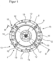
- the FIG. 1 shows a balancing device 1 for a fuselage group 2 of a turbocharger.
- the fuselage group 2 comprises a shaft 3, at the ends of which in each case a turbine wheel 4 or a compressor wheel 5 of the turbocharger are fastened and fixed via a shaft nut 3a.
- the balancing device 1 is provided with a base body 6, which has a centrally arranged receptacle 7 in order to insert the body group 2 into the receptacle 7 and to keep the rotation element 3, 4, 5 rotating about its axis of rotation via bearings which are not shown in detail.
- a plurality of hydraulic cylinders 8 arranged around the receptacle 7 are provided, by means of which the trunk group 2 is arranged in the central position Recording 7 is attached.
- the main body 6 has a circular decoupling plate 9, which comprises an inner plate section 10 and an outer plate section 11, which is elastically connected to the inner plate section 10 and surrounds the inner plate section 10, fixed in the balancing device 1.
- the decoupling plate 9 are along the circumference of the decoupling plate 9, d. H. along a circular arc about the central axis of rotation of the rotary member 3, 4, 5 arranged circumferential slots 12 are provided, via which the inner plate portion 10 is resiliently decoupled from the outer plate portion 11.
- the circumferential slots 12 are arranged so that they extend almost along the entire circumference of the decoupling plate 9.
- the individual circumferential slots 12 are spaced from each other in such a way that four, separate holding portions 13 in the decoupling plate 9 form.
- the circumferential slots 12 are each arranged over a length of 80 ° of the circumferential length of each holding section 13 of the decoupling plate 9.
- Recesses in the form of spring webs 14 and spring lugs 15 are provided in the decoupling plate 9 at the end regions of the circumferential slots 12, which are adapted to the expected load in the holding sections 13, ie in the region of expected bending and torsional forces as spring lugs 15, 10 Range of expected due to up and down movements caused linear forces as spring bars 14th
- the end portions of the circumferential slots 12 at the 12 o'clock position and at the 6 o'clock position are spring lugs 15 which are arranged to overlap one another at a distance from each other in the formation of the nose shape and capable of compressing vibrations due to rotations.
- the end regions of two adjacent peripheral slots 12 are designed as spring webs 14, which extend at a distance from one another parallel to the center axis of the decoupling plate 9.
- only three holding portions are provided on the decoupling plate 9, each extending over an angular range of 100 ° along the circumference of the base body 6.
- this embodiment will not be discussed further in this embodiment.
- the circumferential slots 12 and recesses 14, 15 have been introduced in the present embodiment by means of water jet cutting in the decoupling plate 9.
- the decoupling plate 9 is therefore further formed in one piece. Due to the various embodiments of the circumferential slots 12 and recesses 14, 15 and the webs 14a, 15a formed between them, a resilient mounting of the inner plate portion 10 from the stationary outer plate portion 11 while compensating for the effects of force due to the rotation and the mass movements achieved the various components. This is equivalent to a decoupling of the inner plate portion 10 from the stationary outer plate portion 11, which is accompanied by a significant reduction of the masses to be moved during the balancing process.
- pneumatic cylinder In order to fix the fuselage group 2 in the central receptacle 7 of the decoupling plate 9, first, attached to the outer plate portion 11, not shown pneumatic cylinder is extended. This method of the pneumatic cylinder causes a substantially powerless displacement of the arranged on the inner Plattenabschnit 10 hydraulic cylinder 8 within a provided in the inner plate portion 11 recess 16. By positioning the hydraulic cylinder adjoining the hydraulic cylinder 8 lever elements 17 can be tilted, resulting in a fixation of Allow body group 2 by means provided thereon retaining flanges 18.
Landscapes
- Engineering & Computer Science (AREA)
- Mechanical Engineering (AREA)
- General Engineering & Computer Science (AREA)
- Physics & Mathematics (AREA)
- General Physics & Mathematics (AREA)
- Life Sciences & Earth Sciences (AREA)
- Forests & Forestry (AREA)
- Supercharger (AREA)
- Testing Of Balance (AREA)
Abstract
Description
- Die vorliegende Erfindung betrifft eine Wuchteinrichung, insbesondere für Turbolader, mit einem Grundkörper, der eine zentral angeordnete Aufnahme aufweist, in welcher ein zu wuchtendes Rotationselement, insbesondere eine Rumpfgruppe eines Turboladers, axial einschiebbar ist, um das Rotationselement in der Aufnahme um dessen Rotationsachse drehend zu halten, wobei an dem Grundkörper mehrere, um die Aufnahme herum angeordnete Hydraulikzylinder vorgesehen sind, mittels welcher das Rotationselement in der zentralen Aufnahme fixiert oder fixierbar ist.
- Wuchteinrichtungen der oben genannten Art zur dynamischen Messung von Unwuchten auf einem Rotationselement sind allgemein bekannt. Insbesondere bei Turboladern ist es notwendig, Drehgeschwindigkeit zwischen 20.000 und über 200.000 Umdrehungen pro Minute und die dabei entstehenden Unwuchten beziehungsweise Vibrationen zu messen.
- Dazu wird im Stand der Technik vorgeschlagen, dass Rotationselement - hier in der Form einer Rumpfgruppe eines Turboladers, welche aus einem Verdichterrad und einem Turbinenrad zusammengesetzt ist, die über eine Welle mit einer Wellenmutter zur dynamischen Messung von Unwuchten in einer oder mehreren Ebenen miteinander gekoppelt sind, in die Wuchteinrichtung einzusetzen. Dazu wird die Rumpfgruppe in eine in der Wuchteinrichtung ausgebildete zentrale Aufnahme geschoben und darin fixiert. Anschließend wird das Rotationselement in Drehung versetzt und über Sensoren Unwuchten des Rotationselementes detektiert.
- Die Befestigung der Rumpfgruppe in der Wuchteinrichtung erfolgt häufig über an der zentralen Aufnahme angebrachte Bolzen. Nachteilig an einer solchen Lösung ist jedoch, dass die Fixierung der Rumpfgruppe jeweils sehr viel Zeit in Anspruch nimmt, was die Taktzeiten der Wuchteinrichtung deutlich verlängert.
- Zur Verringerung der Taktzeiten wurde im Stand der Technik vorgeschlagen, die Rumpfgruppe mit einer Trägerstruktur in der zentralen Aufnahme zu fixieren, wobei die Trägerstruktur parallel zur Rotationsachse der Rumpfgruppe verschoben wird. Diese Form von Trägerstrukturen sind jedoch sehr sperrig und massiv und erhöhen somit die bei dem Wuchtvorgang zu beschleunigenden Massen, was zu einer Verfälschung des Wuchtergebnisses führen kann.
- Um diesem Problem zu entgehen, wird in der
US 9,261,110 B2 - Nachteilig an dieser Ausbildung des Entkopplungselements ist jedoch, dass die Rumpfgruppe über an dem Basiselement befestigte Hydraulikzylinder an der Struktur befestigt werden muss. Um eine damit einhergehende Vergrößerung der Masse entgegenzuwirken, wird in der
US 9, 261, 110 B2 - Zum anderen besteht bei einer Fehlbestückung der Wuchteinrichtung wie beispielsweise ein Nichteinsetzen der Rumpfgruppe die Gefahr, dass sich die Hydraulikzylinder nebst Fensterelementen aufgrund der radialen Krafteinwirkung der Hydraulikzylinder zur axialen Fixierung der Rumpfgruppe und der damit einhergehenden Krafteinwirkung auf das Entkopplungselement derart in die Aufnahme hinein bewegen, dass es schließlich zu einem Bruch der zwischen Basisstruktur und Trägerstruktur ausgebildeten Federelemente kommt. Als Folge muss das einteilig ausgebildete Entkopplungselement vollständig erneuert werden, da die zwischen den Basiselement und der Stützelement vorgesehenen Federelemente nicht ersetzt werden können.
- Es ist daher Aufgabe der vorliegenden Erfindung, eine Wuchteinrichtung bereitzustellen, die einen einfacheren und sicheren Aufbau aufweist.
- Diese Aufgabe wird durch die kennzeichnenden Merkmale des Patentanspruchs 1 gelöst, indem der Grundkörper als Entkopplungsplatte ausgebildet ist, die einen inneren Plattenabschnitt und einen mit dem inneren Plattenabschnitt elastisch verbundenen, den inneren Plattenabschnitt umgebenden, ortsfest angeordneten äußeren Plattenabschnitt aufweist, wobei der Grundkörper mehrere Umfangsschlitze aufweist, über welche der innere Plattenabschnitt vom äußeren Plattenabschnitt federnd entkoppelt ist, derart, dass sich mehrere, voneinander getrennte Halteabschnitte auf der Entkopplungsplatte bilden.
- Mit anderen Worten ist erfindungsgemäß vorgesehen, von den im Stand der Technik bekannten einzelnen Federelementen zwischen den Plattenelementen Abstand zu nehmen und stattdessen auf der Entkopplungsplatte in Umfangsrichtung angeordnete Umfangsschlitze vorzusehen, die es ermöglichen, dass sich der innere Plattenabschnitt losgelöst vom ortsfesten fixierten äußeren Plattenabschnitt federnd bewegen kann.
- Die Entkopplungsplatte wird durch Vorsehen der Umfangsschlitze in zwei Plattenabschnitte - einen inneren und einen äußeren Plattenabschnitt - aufgeteilt. Dies hat zur Folge, dass der innere Plattenabschnitt durch die Umfangsschlitze von dem äußeren ortsfesten Plattenabschnitt getrennt und so in ausreichendem Maße gegenüber dem äußeren Plattenabschnitt elastisch gehalten ist.
- Die einteilig ausgebildete Entkopplungsplatte an sich bleibt dabei im Wesentlichen stabil, was sich gerade für den Fall einer Fehlbestückung der Wuchteinrichtung positiv auswirkt, da die Stabilität der Entkopplungsplatte im Wesentlichen erhalten bleibt und so beispielsweise einer Überbelastung wie bei den im Stand der Technik bekannten Federelementen erfolgreich entgegengewirkt wird.
- Bei einer bevorzugten Ausführungsform der Erfindung ist vorgesehen, dass sich die Umfangsschlitze jeweils über eine Länge von wenigstens 70%, insbesondere wenigstens 80% der Gesamtlänge des jeweiligen Halteabschnittes auf der Entkopplungsplatte erstrecken.
- In bevorzugter Weise ist die Entkopplungsplatte kreisförmig ausgebildet und die Umfangsschlitze der Halteabschnitte verlaufen jeweils parallel zu den Außenwandungen des äußeren Plattenabschnittes.
- Die Umfangsschlitze definieren jeweils wenigstens einen Halteabschnitt, wobei die Umfangsschlitze derart entlang des inneren und äußeren Plattenabschnittes ausgebildet sind, dass sie an die zu erwartende Art der bei der Rotation des Rotationselementes entstehenden Kräfte und Momente angepasst sind.
- An Endbereichen der Umfangsschlitze können zumindest teilweise Ausnehmungen, insbesondere in Form von Federstegen oder -nasen in der Entkopplungsplatte vorgesehen sein. Dabei können die Federstege oder -nasen an den Endbereichen der Umfangsschlitze parallel zueinander verlaufen und insbesondere parallel zu einer zwischen den Halteabschnitten liegenden Längsmittelebene der Entkopplungsplatte ausgerichtet sein.
- Benachbarte Halteabschnitte können unmittelbar durch Vorsehen mindestens einer Ausnehmung voneinander getrennt werden, wenn beispielsweise Umfangsschlitze der beiden benachbarten Halteabschnitte in die gleiche Ausnehmung münden. So ist es möglich, mindestens zwei benachbarte Umfangsschlitze unmittelbar durch jeweils radial verlaufende Ausnehmungen voneinander zu trennen.
- Alternativ ist es auch möglich, die Umfangsschlitze beabstandet zueinander anzuordnen und zur Bildung der Halteabschnitte zumindest teilweise in ihren Endbereichen überlappend auszubilden beziehungsweise Ausnehmungen in den Endbereichen der Umfangsschlitze so anzuordnen, dass sie überlappend angeordnet sind.
- Gemäß einer Ausführungsform der Erfindung ist vorgesehen, dass eine geradzahlige Anzahl von Halteabschnitten an der Grundplatte angeordnet sind, die insbesondere spiegelsymmetrisch zu einer Längsmittelebene der Entkopplungsplatte ausgebildet sein können.
- Alternativ ist es auch möglich, insgesamt drei Halteabschnitte an der Entkopplungsplatte vorzusehen, die sich insbesondere jeweils in einem Winkelbereich von wenigstens 70°, insbesondere wenigstens 80° und besonders bevorzugt wenigstens 100° entlang des Umfangs des Grundkörpers erstrecken.
- Natürlich ist es auch möglich, insgesamt zwei Paare von Halteabschnitten vorzusehen, die bezüglich zweier senkrecht zueinander stehende Längsmittelebenen des Grundkörpers spiegelsymmetrisch angeordnet und ausgebildet sind.
- Die Umfangsschlitze und/oder die Ausnehmung können mittels Wasserstrahlschneiden und/oder Drahterosion in den Grundkörper eingebracht werden.
- In einer besonders bevorzugten Ausführungsform der vorliegenden Erfindung ist ferner vorgesehen, dass das Rotationselement durch eine im Wesentlichen axiale Verschiebungen der an den Halteabschnitten vorgesehenen Hydraulikzylinder in der zentralen Aufnahme des Grundkörpers verspannt oder verspannbar ist.
- Wenn die Hydraulikzylinder an dem inneren Plattenabschnitt angeordnet und befestigt sind, kann so erreicht werden, dass sämtliche weiteren, an der Wuchteinrichtung vorgesehene Massen gesamthaft an dem ortsfest an dem zu der Wuchteinrichtung fixierten äußeren Plattenabschnitt verbleiben, so dass die Rotationsbewegung des Rotationselementes mit deutlich geringerer Zusatzmasse erfolgen kann, da lediglich eine Rotation des inneren Plattenabschnittes zusammen mit den Hydraulikzylindern erfolgen kann. Die Gefahr einer Verfälschung der Messergebnisse kann so deutlich verringert werden. Die Hydraulikzylinder können innerhalb des inneren Plattenabschnitts axial, also parallel zur Rotationsachse des Rotationselement derart verfahrbar sein, dass sich an die Hydraulikzylinder anschließende Hebelelemente durch deren axiale Verschiebung so verkippen lassen, dass sich eine kraft- und/oder formflüssige Verbindung zwischen den Hebelelementen und dem Rotationselement einstellt.
- Eine Verbesserung der Automatisierbarkeit des Verfahrens zum Wuchten von Rumpfgruppen beziehungsweise Rotationselementen sieht vor, an dem äußeren ortsfesten Plattenabschnitt mehrere Pneumatikzylinder vorzusehen, um die Hydraulikzylinder und/oder die Hebelelemente nach Einsetzen des Rotationselementes in die zentrale Aufnahme an dem zu befestigenden Rotationselement zu positionieren und anschließend die ortsfest an dem äußeren Plattenabschnitt befestigten Pneumatikzylinder nach der Fixierung des Rotationselementes mittels der Hebelelemente in der zentralen Aufnahme zurückzufahren. So ist es möglich, eine automatische Positionierung der Hebelelemente an den zu befestigenden Rotationselement bereitzustellen und zu verhindern, dass weitere die Vibration des Rotationselement beeinträchtigende Massen den Wuchtvorgang beispielsweise durch die Pneumatikzylinder beeinflussen.
- Um auch einen schnellen Ausbau des Grundkörpers aus der Wuchteinrichtung beispielsweise bei Wechsel der äußeren Abmessung des Rotationselementes bzw. der Rumpfgruppe zu ermöglichen, ist in einem Ausführungsbeispiel vorgesehen, dass die Wuchteinrichtung eine Basisplatte aufweist, mittels welcher die Wuchteinrichtung beispielsweise mit Druckluft und Hydrauliköl versorgt werden kann, an welche eine an dem Grundkörper vorgesehene Adapterplatte einfach aufgeschoben werden kann. So entfallen bei einem Werkzeugwechsel zusätzliche Arbeitsschritte wie beispielsweise Bereitstellung einer Luft- oder Hydraulikölzufuhr oder ähnliches.
- Hinsichtlich weiterer vorteilhafter Ausgestaltung der Erfindung wird auf die Unteransprüche sowie die nachfolgende Beschreibung von Ausführungsbeispielen anhand der Zeichnungen verwiesen.
- In der Zeichnung zeigt
- Figur 1
- eine erfindungsgemäße Entkopplungsplatte in Draufsicht;
- Figur 2
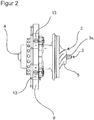
- eine erfindungsgemäße Entkopplungsplatte mit eingesetzter Rumpfgruppe von der Seite;
- Figur 3
- eine Schnittdarstellung der Entkopplungsplatte entlang der Schnittlinie AA gemäß
Figur 1 ; und - Figur 4
- eine Teildarstellung der erfindungsgemäßen Kopplungsplatte mit eingesetzter Rumpfgruppe gemäß Schnitt B-B in der
Figur 3 . - Die
Figur 1 zeigt eine Wuchteinrichtung 1 für eine Rumpfgruppe 2 eines Turboladers. Die Rumpfgruppe 2 umfasst eine Welle 3, an deren Enden jeweils ein Turbinenrad 4 beziehungsweise ein Verdichterrad 5 des Turboladers befestigt und über eine Wellenmutter 3a fixiert sind. - Die Wuchteinrichtung 1 ist mit einem Grundkörper 6 versehen, der eine zentral angeordnete Aufnahme 7 aufweist, um die Rumpfgruppe 2 in die Aufnahme 7 einzuschieben und das Rotationselement 3, 4, 5 um seine Rotationsachse drehend über nicht näher dargestellte Lager zu halten. An dem Grundkörper 6 sind mehrere, um die Aufnahme 7 herum angeordnete Hydraulikzylinder 8 vorgesehen, mittels welcher die Rumpfgruppe 2 in der zentralen Aufnahme 7 befestigt ist.
- Der Grundkörper 6 weist eine kreisförmige Entkopplungsplatte 9 auf, die einen inneren Plattenabschnitt 10 und einen mit dem inneren Plattenabschnitt 10 elastisch verbundenen, den inneren Plattenabschnitt 10 umgebenden, ortsfest in der Wuchteinrichtung 1 angeordneten äußeren Plattenabschnitt 11 umfasst.
- In der Entkopplungsplatte 9 sind entlang des Umfangs der Entkopplungsplatte 9, d. h. entlang eines Kreisbogens um die zentrale Drehachse des Rotationselementes 3, 4, 5 angeordnete Umfangsschlitze 12 vorgesehen, über welche der innere Plattenabschnitt 10 vom äußeren Plattenabschnitt 11 federnd entkoppelt ist.
- Die Umfangsschlitze 12 sind dabei so angeordnet, dass sie sich nahezu entlang des gesamten Umfangs des Entkopplungsplatte 9 erstrecken. Die einzelnen Umfangsschlitze 12 sind derart voreinander beabstandet, dass sich vier, voneinander getrennte Halteabschnitte 13 in der Entkopplungsplatte 9 ausbilden. Dazu sind die Umfangsschlitze 12 jeweils über eine Länge von 80 ° der Umfangslänge eines jeden Halteabschnittes 13 der Entkopplungsplatte 9 angeordnet.
- An den Endbereichen der Umfangsschlitze 12 sind Ausnehmungen in Form von Federstegen 14 und Federnasen 15 in der Entkopplungsplatte 9 vorgesehen, die auf die zu erwartende Belastung in den Halteabschnitten13 angepasst ausgebildet sind, d.h. im Bereich von zu erwartenden Biege- und Torsionskräften als Federnasen 15, im Bereich von zu erwartenden durch Auf- und Abwärtsbewegungen hervorgerufenen Linearkräften als Federstege 14.
- Wie in
Figur 1 genauer zu sehen ist, handelt es sich bei den Endbereichen der Umfangsschlitze 12 in der 12-Uhr-Position und in der 6-Uhr-Position um Federnasen 15, die so angeordnet sind, dass sie sich beabstandet voneinander im Bereich der Ausbildung der Nasenform überlappen und dazu geeignet sind Schwingungen aufgrund von Rotationen zu komprimieren. - In der 3-Uhr und 9-Uhr-Position hingegen sind die Endbereiche zweier benachbarter Umfangsschlitze 12 als Federstege 14 ausgebildet, die sich beabstandet zueinander parallel zum Achsmittelpunkt der Entkopplungsplatte 9 hin erstrecken.
- Zur Fixierung der Rumpfgruppe 2 an der Entkopplungsplatte 9 ist mit vier Halteabschnitten 13 eine geradzahlige Anzahl vorgesehen, die spiegelsymmetrisch zu einer Längsmittelebene der Entkopplungsplatte 9 angeordnet sind.
- In einem nicht dargestellten Ausführungsbeispiel sind lediglich drei Halteabschnitte an der Entkopplungsplatte 9 vorgesehen, die sich jeweils über einen Winkelbereich von 100° entlang des Umfangs des Grundkörpers 6 erstrecken. Auf diese Ausführungsform wird in diesem Ausführungsbeispiel jedoch nicht weiter eingegangen.
- Die Umfangsschlitze 12 und Ausnehmungen 14, 15 sind im vorliegenden Ausführungsbeispiel mittels Wasserstrahlschneiden in die Entkopplungsplatte 9 eingebracht worden. Die Entkopplungsplatte 9 ist demnach weiterhin einteilig ausgebildet. Durch die verschiedenen Ausbildungsformen der Umfangsschlitze 12 und Ausnehmungen 14, 15 und der zwischen ihnen ausgebildeten Stege 14a, 15a wird eine federnde Lagerung des inneren Plattenabschnittes 10 vom ortsfesten äußeren Plattenabschnitt 11 unter Ausgleich von Krafteinwirkungen aufgrund der mit der Rotation und der Massenbewegungen der verschiedenartigen Bauteile erreicht. Dies ist gleichzusetzen mit einer Entkopplung des inneren Plattenabschnitts 10 vom ortsfesten äußeren Plattenabschnitt 11, was mit einer deutlichen Reduktion der zu bewegenden Massen während des Wuchtungsvorganges einhergeht.
- Um die Rumpfgruppe 2 in der zentralen Aufnahme 7 der Entkopplungsplatte 9 zu fixieren, werden zunächst an dem äußeren Plattenabschnitt 11 angebrachte, nicht dargestellte Pneumatikzylinder ausgefahren. Dieses Verfahren der Pneumatikzylinder ruft eine im Wesentlichen kraftlose Verschiebung der an dem inneren Plattenabschnit 10 angeordneten Hydraulikzylinder 8 innerhalb einer in dem inneren Plattenabschnitt 11 vorgesehenen Ausnehmung 16 hervor, Durch Positionierung der Hydraulikzylinder können an den Hydraulikzylinder 8 anschließende Hebelelemente 17 verkippt werden, was eine Fixierung der Rumpfgruppe 2 mittels daran vorgesehenen Halteflanschen 18 ermöglichen.
- Dies erfolgt durch eine im Wesentlichen axiale Verschiebung der Hydraulikzylinder 8 also auch achsparallel zur zentralen Achse der Rumpfgruppe 2, was zu einer Verkippung der sich daran anschließenden Hebelelemente 17 führt, wodurch die Hebelelemente 17 mit dem Halteflansch 18 der Rumpfgruppe 2 in Verbindung gelangen und so die Rumpfgruppe 2 in gespannter Position an dem inneren Plattenabschnitt 11 fixiert wird. Mit anderen Worten wird durch die im Wesentlichen axiale beziehungsweise achsparallele Verschiebung der Hydraulikzylinder 8 eine kraft- und/oder formschlüssigen Verbindung zwischen den Hebelelementen 17 und der Rumpfgruppe 2 erreicht.
Claims (13)
- Wuchteinrichung (1), insbesondere für Turbolader, mit einem Grundkörper (6), der eine zentral angeordnete Aufnahme (7) aufweist, in welcher ein zu wuchtendes Rotationselement (3, 4. 5), insbesondere eine Welle (3) eines Turboladers, axial einschiebbar ist, um das Rotationselement (3, 4, 5) in der Aufnahme (7) um dessen Rotationsachse drehend zu halten, wobei an dem Grundkörper (6) mehrere, um die zentrale Aufnahme (7) herum angeordnete Hydraulikzylinder (8) vorgesehen sind, mittels welcher das Rotationselement, insbesondere eine Rumpfgruppe (2) des Turboladers in der zentralen Aufnahme (7) fixierbar ist, dadurch gekennzeichnet, dass der Grundkörper (6) als Entkopplungsplatte (9) ausgebildet ist, die einen inneren Plattenabschnitt (10) und einen mit dem inneren Plattenabschnitt (10) elastisch verbundenen, den inneren Plattenabschnitt (10) umgebenden, ortsfest angeordneten äußeren Plattenabschnitt (11) aufweist, wobei die Entkopplungsplatte (9) mehrere Umfangsschlitze (12) aufweist, über welche der innere Plattenabschnitt (10) vom äußeren Plattenabschnitt (11) federnd entkoppelt ist, derart, dass sich mehrere, voneinander getrennte Halteabschnitte (13) auf der Entkopplungsplatte (9) bilden.
- Wuchteinrichtung (1) nach Anspruch 1, dadurch gekennzeichnet, dass sich die Umfangsschlitze (12) jeweils über eine Länge von wenigstens 70%, insbesondere wenigstens 80% der Gesamtlänge eines jeden Halteabschnittes (13) der Entkopplungsplatte (9) erstrecken.
- Wuchteinrichtung (1) nach Anspruch 1 oder 2, dadurch gekennzeichnet, dass an den Endbereichen der Umfangsschlitze (12) zumindest teilweise Ausnehmungen, insbesondere Federstege (14) oder -nasen (15) in der Entkopplungsplatte (9) vorgesehen sind.
- Wuchteinrichtung (1) nach Anspruch 3, dadurch gekennzeichnet, dass mindestens zwei benachbarte Umfangsschlitze (12) unmittelbar durch jeweils radial verlaufende Ausnehmungen (14, 15) voneinander getrennt sind.
- Wuchteinrichtung (1) nach einem der Ansprüche 1 bis 3, dadurch gekennzeichnet, dass sich die Umfangsschlitze (12) beabstandet zueinander ausgebildet sind und sich zur Bildung der Halteabschnitte (13) zumindest teilweise in ihren Endbereichen überlappen.
- Wuchteinrichtung (1) nach einem der vorhergehenden Ansprüche, dadurch gekennzeichnet, dass eine geradzahlige Anzahl von Halteabschnitten (13) vorgesehen sind, die spiegelsymmetrisch zu einer Längsmittelebene der Entkopplungsplatte (9) angeordnet und ausgebildet sind.
- Wuchteinrichtung (1) nach einem der Ansprüche 1 bis 5, dadurch gekennzeichnet, dass insgesamt drei Halteabschnitte (13) an der Entkopplungsplatte (9) vorgesehen sind, die sich insbesondere jeweils über einen Winkelbereich von wenigstens 70°, insbesondere wenigstens 80° und besonders bevorzugt wenigstens 100° entlang des Umfangs des Grundkörpers (6) erstrecken.
- Wuchteinrichtung (1) nacheinem der vorhergehenden Ansprüche, dadurch gekennzeichnet, dass die Umfangsschlitze (12) und/oder die Ausnehmungen (14, 15) mittels Wasserstrahlschneiden und/oder mittels Drahterosion in den Grundkörper (6) eingebracht sind.
- Wuchteinrichtung (1) nach einem der vorhergehenden Ansprüche, dadurch gekennzeichnet, dass das Rotationselement (3, 4, 5) durch eine im Wesentlichen axiale Verschiebung der Hydraulikzylinder (8) in der zentralen Aufnahme (7) des Grundkörpers (6) verspannt oder verspannbar ist.
- Wuchteinrichtung (1) nach einem der vorhergehenden Ansprüche, dadurch gekennzeichnet, dass die Hydraulikzylinder (8) an dem inneren Plattenabschnitt (10) angeordnet oder befestigt sind.
- Wuchteinrichtung (1) nach einem der vorhergehenden Ansprüche, dadurch gekennzeichnet, dass die Hydraulikzylinder (8) innerhalb des inneren Plattenabschnittes (10) achsparallel zur Rotationsachse des Rotationselements (3, 4, 5) derart verfahrbar sind, dass sie an die Hydraulikzylinder (8) sich anschließende Hebelelemente (17) so verschieben, dass sich eine kraft- und/oder formflüssige Verbindung zwischen den Hebelelementen (17) und der Rumpfgruppe (2) einstellt.
- Wuchteinrichtung (1) nach einem der vorhergehenden Ansprüche, dadurch gekennzeichnet, dass an dem äußeren ortsfesten Plattenabschnitt (11) mehrere Pneumatikzylinder vorgesehen sind, um die Hydraulikzylinder (8) und/ oder die Hebelelemente (17) an der Rumpfgruppe (2) zu positionieren.
- Wuchteinrichtung (1) nach einem der vorhergehenden Ansprüche, dadurch gekennzeichnet, dass sie eine Adapterplatte aufweist, die zur Speisung des Grundkörpers (6) der Wuchteinrichtung (1) mit Druckluft und Hydrauliköl mit einer in der Wuchteinrichtung (1) fixierten Basisplatte koppelbar ist.
Priority Applications (8)
| Application Number | Priority Date | Filing Date | Title |
|---|---|---|---|
| HUE17158764A HUE055823T2 (hu) | 2017-03-01 | 2017-03-01 | Kiegyensúlyozó szerkezet |
| EP17158764.5A EP3370052B1 (de) | 2017-03-01 | 2017-03-01 | Wuchteinrichtung |
| PL17158764T PL3370052T3 (pl) | 2017-03-01 | 2017-03-01 | Wyważarka |
| JP2018032657A JP6660967B2 (ja) | 2017-03-01 | 2018-02-27 | バランス装置 |
| US15/907,909 US10408229B2 (en) | 2017-03-01 | 2018-02-28 | Balancing device |
| KR1020180024232A KR102130523B1 (ko) | 2017-03-01 | 2018-02-28 | 균형 디바이스 |
| CN201810173098.9A CN108534951B (zh) | 2017-03-01 | 2018-03-01 | 平衡装置 |
| MX2018002622A MX2018002622A (es) | 2017-03-01 | 2018-03-01 | Dispositivo de equilibrio. |
Applications Claiming Priority (1)
| Application Number | Priority Date | Filing Date | Title |
|---|---|---|---|
| EP17158764.5A EP3370052B1 (de) | 2017-03-01 | 2017-03-01 | Wuchteinrichtung |
Publications (2)
| Publication Number | Publication Date |
|---|---|
| EP3370052A1 true EP3370052A1 (de) | 2018-09-05 |
| EP3370052B1 EP3370052B1 (de) | 2021-05-12 |
Family
ID=58264388
Family Applications (1)
| Application Number | Title | Priority Date | Filing Date |
|---|---|---|---|
| EP17158764.5A Active EP3370052B1 (de) | 2017-03-01 | 2017-03-01 | Wuchteinrichtung |
Country Status (8)
| Country | Link |
|---|---|
| US (1) | US10408229B2 (de) |
| EP (1) | EP3370052B1 (de) |
| JP (1) | JP6660967B2 (de) |
| KR (1) | KR102130523B1 (de) |
| CN (1) | CN108534951B (de) |
| HU (1) | HUE055823T2 (de) |
| MX (1) | MX2018002622A (de) |
| PL (1) | PL3370052T3 (de) |
Citations (3)
| Publication number | Priority date | Publication date | Assignee | Title |
|---|---|---|---|---|
| US4864859A (en) * | 1988-07-25 | 1989-09-12 | Allied-Signal Inc. | Method for dynamically balancing a mechanism having a high speed rotating component |
| DE102005053786A1 (de) * | 2005-11-09 | 2007-05-10 | Schenck Rotec Gmbh | Verfahren und Vorrichtung zum dynamischen Messen der Unwucht eines Rotors |
| US9261110B2 (en) | 2012-04-06 | 2016-02-16 | Carlo Buzzi | Balancing device, particularly for turbocompressors, and corresponding method |
Family Cites Families (8)
| Publication number | Priority date | Publication date | Assignee | Title |
|---|---|---|---|---|
| JP2733767B2 (ja) * | 1988-02-02 | 1998-03-30 | 本田技研工業株式会社 | ターボ回転機のバランス確認装置 |
| DE19627921A1 (de) * | 1996-07-11 | 1998-01-15 | Leybold Vakuum Gmbh | Verfahren zum Wuchten eines Rotors sowie für die Durchführung dieses Verfahrens geeigneter Rotor |
| DE102007032608B4 (de) * | 2007-07-11 | 2009-05-07 | Schenck Rotec Gmbh | Verfahren und Vorrichtung zum Zentrieren und Spannen eines Werkstücks in einer Auswuchtmaschine |
| DE102007058592A1 (de) * | 2007-12-04 | 2009-06-10 | Schenck Rotec Gmbh | Vorrichtung zum dynamischen Messen der Unwucht des Rotors eines Turboladers |
| DE102008049144A1 (de) * | 2008-09-26 | 2010-04-01 | Bosch Mahle Turbo Systems Gmbh & Co. Kg | Vorrichtung zum Auswuchten eines Rotors |
| FR2997138B1 (fr) * | 2012-10-18 | 2014-11-14 | Snecma | Dispositif et procede de commande du calage des pales |
| JP5974370B2 (ja) * | 2013-03-18 | 2016-08-23 | 株式会社Ihi | 回転機械支持装置 |
| JP6596749B2 (ja) * | 2015-10-28 | 2019-10-30 | 三菱日立パワーシステムズ株式会社 | 回転機械及び回転機械の制御方法 |
-
2017
- 2017-03-01 HU HUE17158764A patent/HUE055823T2/hu unknown
- 2017-03-01 PL PL17158764T patent/PL3370052T3/pl unknown
- 2017-03-01 EP EP17158764.5A patent/EP3370052B1/de active Active
-
2018
- 2018-02-27 JP JP2018032657A patent/JP6660967B2/ja active Active
- 2018-02-28 US US15/907,909 patent/US10408229B2/en active Active
- 2018-02-28 KR KR1020180024232A patent/KR102130523B1/ko active Active
- 2018-03-01 CN CN201810173098.9A patent/CN108534951B/zh active Active
- 2018-03-01 MX MX2018002622A patent/MX2018002622A/es unknown
Patent Citations (3)
| Publication number | Priority date | Publication date | Assignee | Title |
|---|---|---|---|---|
| US4864859A (en) * | 1988-07-25 | 1989-09-12 | Allied-Signal Inc. | Method for dynamically balancing a mechanism having a high speed rotating component |
| DE102005053786A1 (de) * | 2005-11-09 | 2007-05-10 | Schenck Rotec Gmbh | Verfahren und Vorrichtung zum dynamischen Messen der Unwucht eines Rotors |
| US9261110B2 (en) | 2012-04-06 | 2016-02-16 | Carlo Buzzi | Balancing device, particularly for turbocompressors, and corresponding method |
Also Published As
| Publication number | Publication date |
|---|---|
| HUE055823T2 (hu) | 2021-12-28 |
| KR102130523B1 (ko) | 2020-07-07 |
| JP6660967B2 (ja) | 2020-03-11 |
| JP2018163145A (ja) | 2018-10-18 |
| CN108534951A (zh) | 2018-09-14 |
| US20180252235A1 (en) | 2018-09-06 |
| CN108534951B (zh) | 2020-08-18 |
| EP3370052B1 (de) | 2021-05-12 |
| KR20180100492A (ko) | 2018-09-11 |
| MX2018002622A (es) | 2018-11-09 |
| US10408229B2 (en) | 2019-09-10 |
| PL3370052T3 (pl) | 2021-11-15 |
Similar Documents
| Publication | Publication Date | Title |
|---|---|---|
| EP0733816B1 (de) | Drehgelenk | |
| EP2927661A2 (de) | Aktuator | |
| EP1771713B1 (de) | Wuchtring und verfahren zum auswuchten eines rotierenden bauteils | |
| DE102012206755A1 (de) | Steuerstangenanordnung | |
| EP2428788B1 (de) | Vorrichtung zur Drehlagerung eines auszuwuchtenden Rotors | |
| EP4051918B1 (de) | Prüfstand | |
| DE602005004737T2 (de) | Leitschaufelstufe eines Leitapparates die von einen drehbaren Ring angetrieben wird wobei der Ring von Elektromotoren versetzt wird | |
| WO2020234116A1 (de) | Radhalter | |
| WO1993020362A1 (de) | Hilfslagersystem für einen am stator schwebend gelagerten rotor | |
| EP1952906B1 (de) | Richtrotor und Rotorrichter | |
| EP3370052B1 (de) | Wuchteinrichtung | |
| DE2934710C2 (de) | Rotor zur Drehenergiespeicherung | |
| EP2041452B1 (de) | Auswuchtvorrichtung und verfahren | |
| DE202017101161U1 (de) | Wuchteinrichtung | |
| DE4335785A1 (de) | Ruderstelleinrichtung | |
| DE202017007453U1 (de) | Wuchteinrichtung | |
| DE3600721C2 (de) | ||
| DE60215327T2 (de) | Turbinen- oder kompressorvorrichtung und verfahren zur montage der vorrichtung | |
| EP0402607B1 (de) | Vorrichtung zum Ausrichten eines Gegengewichts und Verfahren zum ausgerichteten Befestigen eines Gegengewichts an einer Kurbelwelle mit Hilfe der Vorrichtung | |
| EP2397657B1 (de) | Verfahren zur Kontrolle der Lagerausrichtung in einer Gas- oder Dampfturbine sowie Gas- oder Dampfturbine | |
| EP2221596B1 (de) | Vorrichtung zum Auswuchten rotierender Körper | |
| EP3375551B1 (de) | Pendelhalter mit einstellbarem radialspiel | |
| EP3976320B1 (de) | Werkzeug zur halterung der hochdruckwelle eines flugzeugtriebwerks | |
| EP0013734B1 (de) | Vorrichtung zum dynamischen Auswuchten von rotierenden Körpern, insbesondere von Schleifscheiben | |
| DE102019208531A1 (de) | Kraftfahrzeugschwingungsdämpfer |
Legal Events
| Date | Code | Title | Description |
|---|---|---|---|
| REG | Reference to a national code |
Ref country code: DE Ref legal event code: R138 Ref document number: 202017007453 Country of ref document: DE Free format text: GERMAN DOCUMENT NUMBER IS 502017010316 |
|
| PUAI | Public reference made under article 153(3) epc to a published international application that has entered the european phase |
Free format text: ORIGINAL CODE: 0009012 |
|
| STAA | Information on the status of an ep patent application or granted ep patent |
Free format text: STATUS: THE APPLICATION HAS BEEN PUBLISHED |
|
| AK | Designated contracting states |
Kind code of ref document: A1 Designated state(s): AL AT BE BG CH CY CZ DE DK EE ES FI FR GB GR HR HU IE IS IT LI LT LU LV MC MK MT NL NO PL PT RO RS SE SI SK SM TR |
|
| AX | Request for extension of the european patent |
Extension state: BA ME |
|
| STAA | Information on the status of an ep patent application or granted ep patent |
Free format text: STATUS: REQUEST FOR EXAMINATION WAS MADE |
|
| 17P | Request for examination filed |
Effective date: 20181123 |
|
| RBV | Designated contracting states (corrected) |
Designated state(s): AL AT BE BG CH CY CZ DE DK EE ES FI FR GB GR HR HU IE IS IT LI LT LU LV MC MK MT NL NO PL PT RO RS SE SI SK SM TR |
|
| STAA | Information on the status of an ep patent application or granted ep patent |
Free format text: STATUS: EXAMINATION IS IN PROGRESS |
|
| 17Q | First examination report despatched |
Effective date: 20200603 |
|
| GRAP | Despatch of communication of intention to grant a patent |
Free format text: ORIGINAL CODE: EPIDOSNIGR1 |
|
| STAA | Information on the status of an ep patent application or granted ep patent |
Free format text: STATUS: GRANT OF PATENT IS INTENDED |
|
| RAP1 | Party data changed (applicant data changed or rights of an application transferred) |
Owner name: CHRISTOPH BOEHMER BETRIEBSVERPACHTUNG GMBH |
|
| RIC1 | Information provided on ipc code assigned before grant |
Ipc: F04D 25/02 20060101ALI20201203BHEP Ipc: F01D 25/28 20060101ALI20201203BHEP Ipc: G01M 1/04 20060101AFI20201203BHEP Ipc: F04D 29/66 20060101ALI20201203BHEP Ipc: F01D 5/02 20060101ALI20201203BHEP |
|
| INTG | Intention to grant announced |
Effective date: 20201221 |
|
| GRAS | Grant fee paid |
Free format text: ORIGINAL CODE: EPIDOSNIGR3 |
|
| GRAA | (expected) grant |
Free format text: ORIGINAL CODE: 0009210 |
|
| STAA | Information on the status of an ep patent application or granted ep patent |
Free format text: STATUS: THE PATENT HAS BEEN GRANTED |
|
| AK | Designated contracting states |
Kind code of ref document: B1 Designated state(s): AL AT BE BG CH CY CZ DE DK EE ES FI FR GB GR HR HU IE IS IT LI LT LU LV MC MK MT NL NO PL PT RO RS SE SI SK SM TR |
|
| REG | Reference to a national code |
Ref country code: GB Ref legal event code: FG4D Free format text: NOT ENGLISH |
|
| REG | Reference to a national code |
Ref country code: CH Ref legal event code: EP |
|
| REG | Reference to a national code |
Ref country code: DE Ref legal event code: R096 Ref document number: 502017010316 Country of ref document: DE |
|
| REG | Reference to a national code |
Ref country code: IE Ref legal event code: FG4D Free format text: LANGUAGE OF EP DOCUMENT: GERMAN |
|
| REG | Reference to a national code |
Ref country code: AT Ref legal event code: REF Ref document number: 1392496 Country of ref document: AT Kind code of ref document: T Effective date: 20210615 |
|
| REG | Reference to a national code |
Ref country code: LT Ref legal event code: MG9D |
|
| REG | Reference to a national code |
Ref country code: NL Ref legal event code: MP Effective date: 20210512 |
|
| PG25 | Lapsed in a contracting state [announced via postgrant information from national office to epo] |
Ref country code: HR Free format text: LAPSE BECAUSE OF FAILURE TO SUBMIT A TRANSLATION OF THE DESCRIPTION OR TO PAY THE FEE WITHIN THE PRESCRIBED TIME-LIMIT Effective date: 20210512 Ref country code: BG Free format text: LAPSE BECAUSE OF FAILURE TO SUBMIT A TRANSLATION OF THE DESCRIPTION OR TO PAY THE FEE WITHIN THE PRESCRIBED TIME-LIMIT Effective date: 20210812 Ref country code: FI Free format text: LAPSE BECAUSE OF FAILURE TO SUBMIT A TRANSLATION OF THE DESCRIPTION OR TO PAY THE FEE WITHIN THE PRESCRIBED TIME-LIMIT Effective date: 20210512 Ref country code: LT Free format text: LAPSE BECAUSE OF FAILURE TO SUBMIT A TRANSLATION OF THE DESCRIPTION OR TO PAY THE FEE WITHIN THE PRESCRIBED TIME-LIMIT Effective date: 20210512 |
|
| PG25 | Lapsed in a contracting state [announced via postgrant information from national office to epo] |
Ref country code: GR Free format text: LAPSE BECAUSE OF FAILURE TO SUBMIT A TRANSLATION OF THE DESCRIPTION OR TO PAY THE FEE WITHIN THE PRESCRIBED TIME-LIMIT Effective date: 20210813 Ref country code: IS Free format text: LAPSE BECAUSE OF FAILURE TO SUBMIT A TRANSLATION OF THE DESCRIPTION OR TO PAY THE FEE WITHIN THE PRESCRIBED TIME-LIMIT Effective date: 20210912 Ref country code: LV Free format text: LAPSE BECAUSE OF FAILURE TO SUBMIT A TRANSLATION OF THE DESCRIPTION OR TO PAY THE FEE WITHIN THE PRESCRIBED TIME-LIMIT Effective date: 20210512 Ref country code: SE Free format text: LAPSE BECAUSE OF FAILURE TO SUBMIT A TRANSLATION OF THE DESCRIPTION OR TO PAY THE FEE WITHIN THE PRESCRIBED TIME-LIMIT Effective date: 20210512 Ref country code: RS Free format text: LAPSE BECAUSE OF FAILURE TO SUBMIT A TRANSLATION OF THE DESCRIPTION OR TO PAY THE FEE WITHIN THE PRESCRIBED TIME-LIMIT Effective date: 20210512 Ref country code: NO Free format text: LAPSE BECAUSE OF FAILURE TO SUBMIT A TRANSLATION OF THE DESCRIPTION OR TO PAY THE FEE WITHIN THE PRESCRIBED TIME-LIMIT Effective date: 20210812 Ref country code: PT Free format text: LAPSE BECAUSE OF FAILURE TO SUBMIT A TRANSLATION OF THE DESCRIPTION OR TO PAY THE FEE WITHIN THE PRESCRIBED TIME-LIMIT Effective date: 20210913 |
|
| REG | Reference to a national code |
Ref country code: HU Ref legal event code: AG4A Ref document number: E055823 Country of ref document: HU |
|
| PG25 | Lapsed in a contracting state [announced via postgrant information from national office to epo] |
Ref country code: NL Free format text: LAPSE BECAUSE OF FAILURE TO SUBMIT A TRANSLATION OF THE DESCRIPTION OR TO PAY THE FEE WITHIN THE PRESCRIBED TIME-LIMIT Effective date: 20210512 |
|
| PG25 | Lapsed in a contracting state [announced via postgrant information from national office to epo] |
Ref country code: SM Free format text: LAPSE BECAUSE OF FAILURE TO SUBMIT A TRANSLATION OF THE DESCRIPTION OR TO PAY THE FEE WITHIN THE PRESCRIBED TIME-LIMIT Effective date: 20210512 Ref country code: SK Free format text: LAPSE BECAUSE OF FAILURE TO SUBMIT A TRANSLATION OF THE DESCRIPTION OR TO PAY THE FEE WITHIN THE PRESCRIBED TIME-LIMIT Effective date: 20210512 Ref country code: RO Free format text: LAPSE BECAUSE OF FAILURE TO SUBMIT A TRANSLATION OF THE DESCRIPTION OR TO PAY THE FEE WITHIN THE PRESCRIBED TIME-LIMIT Effective date: 20210512 Ref country code: ES Free format text: LAPSE BECAUSE OF FAILURE TO SUBMIT A TRANSLATION OF THE DESCRIPTION OR TO PAY THE FEE WITHIN THE PRESCRIBED TIME-LIMIT Effective date: 20210512 Ref country code: CZ Free format text: LAPSE BECAUSE OF FAILURE TO SUBMIT A TRANSLATION OF THE DESCRIPTION OR TO PAY THE FEE WITHIN THE PRESCRIBED TIME-LIMIT Effective date: 20210512 Ref country code: DK Free format text: LAPSE BECAUSE OF FAILURE TO SUBMIT A TRANSLATION OF THE DESCRIPTION OR TO PAY THE FEE WITHIN THE PRESCRIBED TIME-LIMIT Effective date: 20210512 Ref country code: EE Free format text: LAPSE BECAUSE OF FAILURE TO SUBMIT A TRANSLATION OF THE DESCRIPTION OR TO PAY THE FEE WITHIN THE PRESCRIBED TIME-LIMIT Effective date: 20210512 |
|
| REG | Reference to a national code |
Ref country code: DE Ref legal event code: R097 Ref document number: 502017010316 Country of ref document: DE |
|
| PLBE | No opposition filed within time limit |
Free format text: ORIGINAL CODE: 0009261 |
|
| STAA | Information on the status of an ep patent application or granted ep patent |
Free format text: STATUS: NO OPPOSITION FILED WITHIN TIME LIMIT |
|
| 26N | No opposition filed |
Effective date: 20220215 |
|
| PG25 | Lapsed in a contracting state [announced via postgrant information from national office to epo] |
Ref country code: IS Free format text: LAPSE BECAUSE OF FAILURE TO SUBMIT A TRANSLATION OF THE DESCRIPTION OR TO PAY THE FEE WITHIN THE PRESCRIBED TIME-LIMIT Effective date: 20210912 Ref country code: AL Free format text: LAPSE BECAUSE OF FAILURE TO SUBMIT A TRANSLATION OF THE DESCRIPTION OR TO PAY THE FEE WITHIN THE PRESCRIBED TIME-LIMIT Effective date: 20210512 |
|
| PG25 | Lapsed in a contracting state [announced via postgrant information from national office to epo] |
Ref country code: MC Free format text: LAPSE BECAUSE OF FAILURE TO SUBMIT A TRANSLATION OF THE DESCRIPTION OR TO PAY THE FEE WITHIN THE PRESCRIBED TIME-LIMIT Effective date: 20210512 |
|
| GBPC | Gb: european patent ceased through non-payment of renewal fee |
Effective date: 20220301 |
|
| REG | Reference to a national code |
Ref country code: BE Ref legal event code: MM Effective date: 20220331 |
|
| PG25 | Lapsed in a contracting state [announced via postgrant information from national office to epo] |
Ref country code: LU Free format text: LAPSE BECAUSE OF NON-PAYMENT OF DUE FEES Effective date: 20220301 Ref country code: IE Free format text: LAPSE BECAUSE OF NON-PAYMENT OF DUE FEES Effective date: 20220301 Ref country code: GB Free format text: LAPSE BECAUSE OF NON-PAYMENT OF DUE FEES Effective date: 20220301 |
|
| PG25 | Lapsed in a contracting state [announced via postgrant information from national office to epo] |
Ref country code: BE Free format text: LAPSE BECAUSE OF NON-PAYMENT OF DUE FEES Effective date: 20220331 |
|
| P01 | Opt-out of the competence of the unified patent court (upc) registered |
Effective date: 20230404 |
|
| P02 | Opt-out of the competence of the unified patent court (upc) changed |
Effective date: 20230525 |
|
| PG25 | Lapsed in a contracting state [announced via postgrant information from national office to epo] |
Ref country code: MK Free format text: LAPSE BECAUSE OF FAILURE TO SUBMIT A TRANSLATION OF THE DESCRIPTION OR TO PAY THE FEE WITHIN THE PRESCRIBED TIME-LIMIT Effective date: 20210512 Ref country code: CY Free format text: LAPSE BECAUSE OF FAILURE TO SUBMIT A TRANSLATION OF THE DESCRIPTION OR TO PAY THE FEE WITHIN THE PRESCRIBED TIME-LIMIT Effective date: 20210512 |
|
| PG25 | Lapsed in a contracting state [announced via postgrant information from national office to epo] |
Ref country code: TR Free format text: LAPSE BECAUSE OF FAILURE TO SUBMIT A TRANSLATION OF THE DESCRIPTION OR TO PAY THE FEE WITHIN THE PRESCRIBED TIME-LIMIT Effective date: 20210512 |
|
| PG25 | Lapsed in a contracting state [announced via postgrant information from national office to epo] |
Ref country code: MT Free format text: LAPSE BECAUSE OF FAILURE TO SUBMIT A TRANSLATION OF THE DESCRIPTION OR TO PAY THE FEE WITHIN THE PRESCRIBED TIME-LIMIT Effective date: 20210512 |
|
| REG | Reference to a national code |
Ref country code: CH Ref legal event code: U11 Free format text: ST27 STATUS EVENT CODE: U-0-0-U10-U11 (AS PROVIDED BY THE NATIONAL OFFICE) Effective date: 20260401 |
|
| PGFP | Annual fee paid to national office [announced via postgrant information from national office to epo] |
Ref country code: DE Payment date: 20260121 Year of fee payment: 10 |
|
| PGFP | Annual fee paid to national office [announced via postgrant information from national office to epo] |
Ref country code: AT Payment date: 20260304 Year of fee payment: 10 |
|
| PGFP | Annual fee paid to national office [announced via postgrant information from national office to epo] |
Ref country code: HU Payment date: 20260225 Year of fee payment: 10 |
|
| PGFP | Annual fee paid to national office [announced via postgrant information from national office to epo] |
Ref country code: FR Payment date: 20260209 Year of fee payment: 10 |
|
| PGFP | Annual fee paid to national office [announced via postgrant information from national office to epo] |
Ref country code: PL Payment date: 20260220 Year of fee payment: 10 |
|
| PGFP | Annual fee paid to national office [announced via postgrant information from national office to epo] |
Ref country code: IT Payment date: 20260331 Year of fee payment: 10 |
|
| PGFP | Annual fee paid to national office [announced via postgrant information from national office to epo] |
Ref country code: CH Payment date: 20260401 Year of fee payment: 10 |