EP3370038A1 - Position detection device - Google Patents
Position detection device Download PDFInfo
- Publication number
- EP3370038A1 EP3370038A1 EP16859388.7A EP16859388A EP3370038A1 EP 3370038 A1 EP3370038 A1 EP 3370038A1 EP 16859388 A EP16859388 A EP 16859388A EP 3370038 A1 EP3370038 A1 EP 3370038A1
- Authority
- EP
- European Patent Office
- Prior art keywords
- movement trajectory
- magnet
- detection unit
- detection device
- position detection
- Prior art date
- Legal status (The legal status is an assumption and is not a legal conclusion. Google has not performed a legal analysis and makes no representation as to the accuracy of the status listed.)
- Granted
Links
Images


Classifications
-
- G—PHYSICS
- G01—MEASURING; TESTING
- G01B—MEASURING LENGTH, THICKNESS OR SIMILAR LINEAR DIMENSIONS; MEASURING ANGLES; MEASURING AREAS; MEASURING IRREGULARITIES OF SURFACES OR CONTOURS
- G01B7/00—Measuring arrangements characterised by the use of electric or magnetic techniques
- G01B7/003—Measuring arrangements characterised by the use of electric or magnetic techniques for measuring position, not involving coordinate determination
-
- G—PHYSICS
- G01—MEASURING; TESTING
- G01B—MEASURING LENGTH, THICKNESS OR SIMILAR LINEAR DIMENSIONS; MEASURING ANGLES; MEASURING AREAS; MEASURING IRREGULARITIES OF SURFACES OR CONTOURS
- G01B5/00—Measuring arrangements characterised by the use of mechanical techniques
- G01B5/0011—Arrangements for eliminating or compensation of measuring errors due to temperature or weight
- G01B5/0014—Arrangements for eliminating or compensation of measuring errors due to temperature or weight due to temperature
-
- G—PHYSICS
- G01—MEASURING; TESTING
- G01D—MEASURING NOT SPECIALLY ADAPTED FOR A SPECIFIC VARIABLE; ARRANGEMENTS FOR MEASURING TWO OR MORE VARIABLES NOT COVERED IN A SINGLE OTHER SUBCLASS; TARIFF METERING APPARATUS; MEASURING OR TESTING NOT OTHERWISE PROVIDED FOR
- G01D3/00—Indicating or recording apparatus with provision for the special purposes referred to in the subgroups
- G01D3/028—Indicating or recording apparatus with provision for the special purposes referred to in the subgroups mitigating undesired influences, e.g. temperature, pressure
- G01D3/036—Indicating or recording apparatus with provision for the special purposes referred to in the subgroups mitigating undesired influences, e.g. temperature, pressure on measuring arrangements themselves
-
- G—PHYSICS
- G01—MEASURING; TESTING
- G01D—MEASURING NOT SPECIALLY ADAPTED FOR A SPECIFIC VARIABLE; ARRANGEMENTS FOR MEASURING TWO OR MORE VARIABLES NOT COVERED IN A SINGLE OTHER SUBCLASS; TARIFF METERING APPARATUS; MEASURING OR TESTING NOT OTHERWISE PROVIDED FOR
- G01D5/00—Mechanical means for transferring the output of a sensing member; Means for converting the output of a sensing member to another variable where the form or nature of the sensing member does not constrain the means for converting; Transducers not specially adapted for a specific variable
- G01D5/12—Mechanical means for transferring the output of a sensing member; Means for converting the output of a sensing member to another variable where the form or nature of the sensing member does not constrain the means for converting; Transducers not specially adapted for a specific variable using electric or magnetic means
-
- G—PHYSICS
- G01—MEASURING; TESTING
- G01D—MEASURING NOT SPECIALLY ADAPTED FOR A SPECIFIC VARIABLE; ARRANGEMENTS FOR MEASURING TWO OR MORE VARIABLES NOT COVERED IN A SINGLE OTHER SUBCLASS; TARIFF METERING APPARATUS; MEASURING OR TESTING NOT OTHERWISE PROVIDED FOR
- G01D5/00—Mechanical means for transferring the output of a sensing member; Means for converting the output of a sensing member to another variable where the form or nature of the sensing member does not constrain the means for converting; Transducers not specially adapted for a specific variable
- G01D5/12—Mechanical means for transferring the output of a sensing member; Means for converting the output of a sensing member to another variable where the form or nature of the sensing member does not constrain the means for converting; Transducers not specially adapted for a specific variable using electric or magnetic means
- G01D5/14—Mechanical means for transferring the output of a sensing member; Means for converting the output of a sensing member to another variable where the form or nature of the sensing member does not constrain the means for converting; Transducers not specially adapted for a specific variable using electric or magnetic means influencing the magnitude of a current or voltage
- G01D5/142—Mechanical means for transferring the output of a sensing member; Means for converting the output of a sensing member to another variable where the form or nature of the sensing member does not constrain the means for converting; Transducers not specially adapted for a specific variable using electric or magnetic means influencing the magnitude of a current or voltage using Hall-effect devices
- G01D5/145—Mechanical means for transferring the output of a sensing member; Means for converting the output of a sensing member to another variable where the form or nature of the sensing member does not constrain the means for converting; Transducers not specially adapted for a specific variable using electric or magnetic means influencing the magnitude of a current or voltage using Hall-effect devices influenced by the relative movement between the Hall device and magnetic fields
-
- G—PHYSICS
- G01—MEASURING; TESTING
- G01R—MEASURING ELECTRIC VARIABLES; MEASURING MAGNETIC VARIABLES
- G01R33/00—Arrangements or instruments for measuring magnetic variables
- G01R33/02—Measuring direction or magnitude of magnetic fields or magnetic flux
-
- G—PHYSICS
- G01—MEASURING; TESTING
- G01R—MEASURING ELECTRIC VARIABLES; MEASURING MAGNETIC VARIABLES
- G01R33/00—Arrangements or instruments for measuring magnetic variables
- G01R33/02—Measuring direction or magnitude of magnetic fields or magnetic flux
- G01R33/06—Measuring direction or magnitude of magnetic fields or magnetic flux using galvano-magnetic devices
- G01R33/09—Magnetoresistive devices
Definitions
- the present invention relates to a position detection device that detects the relative positions and movement of a magnet and a detection unit having a magnetic sensor.
- PTL 1 describes an invention relating to a position detection device.
- the position detection device has a case accommodating a holder that moves to advance and retreat, and the holder is provided with two magnets that are arranged side by side in a moving direction.
- a detection unit is fixed to the case.
- the detection unit is provided with two magnetoresistive elements facing the magnets that move.
- the holder is urged by a compression coil spring in a direction in which the holder projects from the case.
- a shaft integrally formed with the holder is pressed to move the case in a direction against the urging direction of the compression coil spring, the movement of the magnets is detected with the magnetoresistive elements and the moving position of the holder is calculated.
- the magnetoresistive elements detect a component (Bz) and a component (Bx) of the magnetic flux density of a leakage magnetic field generated by the two magnets, the component (Bz) being in a direction perpendicular to the direction in which the holder moves, the component (Bx) being in a direction parallel to the direction in which the holder moves, to calculate the moving position of the holder. For example, an arc tangent is computed from the detected value of the component (Bz) and the detected value of the component (Bx), and the position of the holder is determined from the computed value.
- the intensity of the leakage magnetic field from the magnets is affected by temperature, and a demagnetization phenomenon in which the magnetic flux density of the leakage magnetic field decreases occurs at a high temperature. It is conventionally recognized that the rate at which the magnetic flux density decreases when a rectangular parallelepiped magnet is heated is always in the same proportion for the component (Bz) in the direction perpendicular to a magnetized surface and the component (Bx) in the direction parallel to the magnetized surface.
- the present invention is intended to address the conventional problem described above, and it is an object of the present invention to provide a position detection device having a structure that makes it easy to ensure the linearity of detection values for detecting the relative movement of a magnet and a detection unit even when a temperature change causes demagnetization of the magnet.
- the present invention provides a position detection device including a detection unit and a magnet facing the detection unit, the detection unit and the magnet being movable relatively to each other, wherein the magnet is magnetized in a direction perpendicular to a relative movement trajectory of the detection unit, and the detection unit includes a magnetic sensor that detects a component of magnetic flux emerging from the magnet that is parallel to the movement trajectory, and a magnetic sensor that detects a component of the magnetic flux that is perpendicular to the movement trajectory, and wherein the magnet has a facing surface facing the movement trajectory, and both ends of the facing surface in a direction extending along the movement trajectory are positioned farther away from the movement trajectory than a center portion of the facing surface.
- the facing surface is a projecting curved surface having a curvature in a direction extending along the movement trajectory.
- the curvature has a radius that is greater than or equal to 1.7 times and less than or equal to 3.4 times a shortest distance between the facing surface and the movement trajectory.
- the position detection device can be configured such that a plurality of the magnets are disposed along the movement trajectory and the facing surfaces of adjacent magnets among the magnets are magnetized to opposite polarities.
- the movement trajectory is a straight line.
- the movement trajectory is an arc of a circle.
- the magnetized surface that is, a surface facing a detection unit, has a shape such that both ends thereof in a direction extending along a relative movement trajectory of the detection unit are positioned more rearward than a center portion thereof.
- This can reduce the difference in demagnetizing factor due to a temperature change between a component of the magnetic flux density in a direction perpendicular to the movement trajectory and a component of the magnetic flux density in a direction parallel to the movement trajectory and can ensure linearity for detection outputs from the detection unit even if a temperature change occurs.
- Fig. 1(A) schematically illustrates the structure of a position detection device 1 according to a first embodiment of the present invention.
- the position detection device 1 includes a movement unit 10.
- the movement unit 10 is provided with a movement unit (not illustrated) that linearly reciprocates in the X direction, and a first magnet 11 and a second magnet 12 are mounted on the movement unit.
- the position detection device 1 is provided with a detection unit 20, and the movement unit 10 and the detection unit 20 face each other in the Z direction.
- the position detection device 1 may have a structure in which the first magnet 11 and the second magnet 12 stop, whereas the detection unit 20 moves. In this case, the relative movement trajectory of the magnets 11 and 12 and the detection unit 20 is also Tx.
- the detection unit 20 faces the middle of the first magnet 11 and the second magnet 12 in the X direction, and the first magnet 11 and the second magnet 12 move to the right or left in the X direction from a neutral position illustrated in Fig. 1(A) .
- the movement unit of the movement unit 10 may be urged leftward in the X direction by an urging member such as a compression coil spring and stop at an initial position.
- an urging member such as a compression coil spring and stop at an initial position.
- the first magnet 11 has a facing surface 11a that faces the movement trajectory Tx, a rear surface 11b opposite the facing surface 11a, and both side surfaces 11c and 11d that are oriented in the X direction.
- the facing surface 11a is part of a cylindrical surface having a curvature in the X direction.
- An opposing distance between the center of the facing surface 11a in the X direction and the movement trajectory Tx is indicated by ⁇ a.
- an opposing distance between an end of the facing surface 11a on the side surface 11c side and the movement trajectory Tx is indicated by ⁇ c
- an opposing distance between an end of the facing surface 11a on the side surface 11d side and the movement trajectory Tx is indicated by ⁇ d.
- the facing surface 11a has a shape such that both ends thereof in the X direction extending along the movement trajectory Tx are positioned farther away from the movement trajectory Tx than a center portion thereof.
- the rear surface 11b of the first magnet 11 is a flat surface that is parallel to the movement trajectory Tx and that is perpendicular to the plane of Fig. 1(A) .
- the side surface 11c and the side surface 11d are flat surfaces that are perpendicular to the movement trajectory Tx and that is perpendicular to the plane of Fig. 1(A) .
- the first magnet 11 is magnetized in the Z direction, which is a direction perpendicular to the movement trajectory Tx, and the facing surface 11a and the rear surface 11b are magnetized surfaces having opposite polarities.
- the facing surface 11a is magnetized to the N pole, and the rear surface 11b is magnetized to the S pole.
- the first magnet 11 and the second magnet 12 have the same size and shape.
- the second magnet 12 also has a facing surface 12a, a rear surface 12b, and side surfaces 12c and 12d.
- the shapes and dimensions of the respective surfaces are the same as those of the first magnet 11.
- the opposing distances ⁇ a, ⁇ c, and ⁇ d between the facing surface 12a and the movement trajectory Tx are also the same as those of the first magnet 11.
- the second magnet 12 is also magnetized in the Z direction, and the facing surface 12a and the rear surface 12b are magnetized surfaces. It is to be noted that the direction of magnetization of the second magnet 12 is reversed to the direction of magnetization of the first magnet 11 by 180 degrees, that is, the facing surface 12a is magnetized to the S pole and the rear surface 12b is magnetized to the N pole.
- the detection unit 20 has at least two magnetic sensors.
- a first magnetic sensor has an axis of sensitivity Sx directed parallel to the movement trajectory Tx and is capable of detecting a magnetic flux density in a direction parallel to the movement trajectory Tx.
- a second magnetic sensor has an axis of sensitivity Sz directed perpendicular to the movement trajectory Tx and is capable of detecting a magnetic flux density in a direction perpendicular to the movement trajectory Tx.
- the magnetic sensors are each constituted by a Hall element, a magnetoresistance effect element, or the like.
- the outputs from the first magnetic sensor and the second magnetic sensor of the detection unit 20 are detected by a detection circuit 2, and each output is subjected to A/D conversion and is provided to a computation unit 3.
- the computation unit 3 is constituted by a CPU, a memory, and so on.
- Fig. 1(B) illustrates a conventional position detection device 101 for comparison and describing the detection operation of the position detection device 1 according to the present invention.
- the position detection device 101 includes a first magnet 111 and a second 112, each of which has a cubic shape, with a facing surface 111a and a facing surface 112a being both flat surfaces that are parallel to the movement trajectory Tx and that are vertical to the plane of Fig. 1(B) .
- a rear surface 111b and a rear surface 112b are flat surfaces that are parallel to the facing surface 111a and the facing surface 112.
- Both the first magnet 111 and the second magnet 112 are magnetized in the Z direction.
- the facing surface 111a of the first magnet 111 is magnetized to the N pole
- the facing surface 112a of the second magnet 112 is magnetized to the S pole.
- An opposing distance ⁇ a between the facing surfaces 111a and 112a and the movement trajectory Tx is the same as the opposing distance ⁇ a at the center portions of the facing surfaces 11a and 12a of the magnets 11 and 12 illustrated in Fig. 1(A) .
- a magnetic field H extending from the facing surface 11a of the first magnet 11 to the facing surface 12a of the second magnet 12 is formed.
- a magnetic field H extending from the facing surface 111a of the first magnet 111 to the facing surface 112a of the second magnet 112 is formed.
- magnetic lines of force that generate the magnetic field H are indicated by broken lines.
- the detection output of the first magnetic sensor having the axis of sensitivity Sx and the detection output of the second magnetic sensor having the axis of sensitivity Sz, which are included in the detection unit 20, exhibit waveforms that are similar to a sine curve and a cosine curve.
- the computation unit 3 computes an arc tangent from changing outputs that are similar to a sine curve and a cosine curve. The computed value of the arc tangent changes substantially linearly, which enables the measurement of the relative movement positions of the movement unit 10 and the detection unit 20.
- each magnet is subjected to demagnetization in which a generated magnetic field decreases when the temperature of the magnet becomes high.
- the present invention has been made focusing on a difference between demagnetizing factors for a component (Bx) and a component (Bz) of the magnetic flux density of a magnetic field emerging from a magnet, which occurs when the temperature of the magnet becomes high, with the component (Bx) being directed in the X direction and the component (Bz) being directed in the Z direction.
- the difference between the demagnetizing factor for the component (Bx) and the demagnetizing factor for the component (Bz) at a high temperature gradually increases toward either end of each of the facing surfaces 111a and 1112a in the X direction from the center portions thereof.
- the facing surfaces 11a and 12a of the magnets 11 and 12 each have a shape such that the opposing distances ⁇ c and ⁇ d between both ends thereof in the X direction and the movement trajectory Tx are longer than the opposing distance ⁇ a between the center portion thereof and the movement trajectory Tx.
- the opposing distance ⁇ d between the facing surface 11a and the movement trajectory Tx becomes large.
- the sensitivity of the component (Bz) of the magnetic flux density in the Z direction, which is detected by the detection unit 20 becomes lower than that when the detection unit 20 faces the center of the facing surface 11a.
- the rate of decrease of the component (Bz) is greater than the rate of decrease of the sensitivity of the component (Bx) of the magnetic flux density in the X direction when the detection unit 20 faces the front of the side surface 11d.
- the facing surface 11a is an inclined curved surface that gradually inclines away from the movement trajectory Tx toward the side surface 11d from the center portion thereof.
- the magnetic field H directed from the facing surface 11a of the first magnet 11 to the facing surface 12a of the second magnet 12 tends to be inclined in the X direction toward the right end of the facing surface 11a.
- This also makes the rate of decrease of the sensitivity of the component (Bz) of the magnetic flux density in the Z direction greater than the rate of decrease of the sensitivity of the component (Bx) in the X direction when the detection unit 20 faces the front of the side surface 11d.
- the component (Bx) of the magnetic flux density in the X direction in front of the side surface 11d attenuates, the component (Bz) of the magnetic flux density in the Z direction, which is detected by the detection unit 20, can be decreased accordingly in accordance with the shape of the facing surface 11a.
- the calculated value of the arc tangent which is computed on the basis of the ratio of the detection output of the first magnetic sensor having the axis of sensitivity Sx and the detection output of the second magnetic sensor having the axis of sensitivity Sz, which are detected by the detection unit 20, can maintain linearity when the detection unit 20 faces the center portion of each of the facing surfaces 11a and 12a in the X direction and when the detection unit 20 faces either end of each of the facing surfaces 11a and 12a in the X direction.
- each of the facing surfaces 11a and 12a of the magnets 11 and 12 need to be gradually inclined such that both ends thereof in the X direction are farther away from the movement trajectory Tx than the center portions thereof.
- each of the facing surfaces 11a and 12a is formed to be a projecting curved surface, which allows the rate of attenuation of the component (Bx) of the magnetic flux density in the X direction that attenuates in a high-temperature environment to easily match the rate of attenuation of the component (Bz) in the Z direction toward either end thereof.
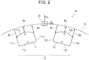
- Fig. 2 illustrates a position detection device 1A according to a second embodiment of the present invention.
- a first magnet 11 and a second magnet 12 that are used in the position detection device 1A are the same as those in the position detection device 1 illustrated in Fig. 1(A) .
- a movement unit 10 having the magnets 11 and 12 rotates, and a relative movement trajectory Tx of the movement unit 10 and a detection unit 20 extends along an arc of a circle.
- the magnets 11 and 12 may be fixed and the detection unit 20 may move along the arc-shaped movement trajectory Tx.
- the opposing distances ⁇ c and ⁇ d between both ends of each of the respective facing surfaces 11a and 12a of the magnets 11 and 12 along the arc-shaped movement trajectory and the movement trajectory Tx are longer than the opposing distance ⁇ a between the center portion thereof and the movement trajectory Tx.
- the difference in the rate of decrease between the detection output in a direction extending along the movement trajectory Tx and the detection output in a direction perpendicular to the movement trajectory Tx can be reduced and linearity can be maintained.
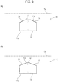
- FIG. 3(A) illustrates a position detection device 1B according to a third embodiment of the present invention.
- a magnet 11B used in the position detection device 1B has a facing surface 11a that is constituted by a flat portion (i) in a center portion thereof, which is parallel to the movement trajectory Tx, and inclined flat portions (ii) on both sides of the flat portion (i).
- FIG. 3(B) illustrates a position detection device 1C according to a fourth embodiment of the present invention.
- a magnet 11C used in the position detection device 1C has a facing surface 11a that is constituted by a projecting curved surface portion (iii) in a center portion thereof and inclined flat portions (ii) on both sides of the projecting curved surface portion (iii).
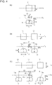
- a position detection device may include only one magnet, as illustrated in Fig. 4(A) , or three or more magnets, as illustrated in Fig. 4(C) .
- Fig. 4(A) illustrates Example 1, in which a single magnet 11 faces the relative movement trajectory Tx of the detection unit 20.
- Fig. 4(B) illustrates Example 2, in which two magnets 11 and 12 face the relative movement trajectory Tx of the detection unit 20.
- Fig. 4(C) illustrates Example 3, in which three magnets 11, 12, and 13 face the relative movement trajectory Tx of the detection unit 20.
- the magnets 11, 12, and 13 have facing surfaces 11a, 12a, and 13a that are projecting curved surfaces having curvatures in a direction extending along the movement trajectory Tx, with their radii of curvature being indicated by R.
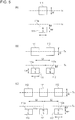
- Fig. 5(A) illustrates Comparative Example 1, in which a single magnet 111 faces the relative movement trajectory Tx of the detection unit 20.
- Fig. 5(B) illustrates Comparative Example 2, in which two magnets 111 and 112 face the relative movement trajectory Tx of the detection unit 20.
- Fig. 5(C) illustrates Comparative Example 3, in which three magnets 111, 112, and 113 face the relative movement trajectory Tx of the detection unit 20.
- the magnets 111, 112, and 113 have facing surfaces 111a, 112a, and 113a that are all flat surfaces.
- the magnets 11, 12, and 13 in Examples and the magnets 111, 112, and 113 in Comparative Examples are each a rare-earth based (Nd-Fe-B based) injection molded magnet.
- the magnets 11, 12, and 13 in Examples and the magnets 111, 112, and 113 in Comparative Examples each have dimensions such that a height Hm is 6 mm, a length L in a direction extending along the movement trajectory Tx is 9 mm, and a width W in a direction perpendicular to the movement trajectory Tx is 9 mm.
- the facing surfaces 11a, 12a, and 13a of the magnets 11, 12, and 13 have a radius of curvature R of 9 mm.
- the opposing distance ⁇ a between the center portions of the facing surfaces of the magnets 11, 12, and 13 in Examples and the movement trajectory Tx and the opposing distance ⁇ a between the respective facing surfaces of the magnets 111, 112, and 113 in Comparative Examples and the movement trajectory Tx, that is, the shortest value of the opposing distance between each magnet and the movement trajectory Tx, are each 3.55 mm.
- an inter-magnet distance S1 is 17 mm
- an inter-magnet distance S2 is 18 mm.
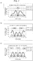
- Figs. 6(A), 6(B), and 6(C) illustrate the moving position of the detection unit 20 and the linearity error for outputs of the detection unit 20 in the respective Examples.
- Figs. 7(A), 7(B), and 7(C) illustrate the moving position of the detection unit 20 and the linearity error for outputs of the detection unit 20 in the respective Comparative Examples.
- the horizontal axis represents the relative positions of each magnet and the detection unit 20 along the movement trajectory Tx.
- Fig. 6(A) illustrates simulation results of Example 1, and the origin "0" of the horizontal axis indicates that, as illustrated in Fig. 4(A) , the detection unit 20 is positioned to face the center of the magnet 11.
- Fig. 6(B) illustrates measurement results of Example 2
- the origin "0" of the horizontal axis indicates that, as illustrated in Fig. 4(B)
- the detection unit 20 is positioned in the middle of the two magnets 11 and 12.
- Fig. 6(C) illustrates measurement results of Example 3 and the origin "0" of the horizontal axis indicates that, as illustrated in Fig. 4(C) , the detection unit 20 is positioned to face the center of the middle magnet 11.
- Fig. 7(A) illustrates measurement results of Comparative Example 1, and the origin "0" of the horizontal axis indicates that, as illustrated in Fig. 5(A) , the detection unit 20 is positioned to face the center of the magnet 111.
- Fig. 7(B) illustrates measurement results of Comparative Example 2
- the origin "0" of the horizontal axis indicates that, as illustrated in Fig. 5(B) , the detection unit 20 is positioned in the middle of the two magnets 111 and 112.
- Fig. 7(C) illustrates measurement results of Comparative Example 3
- the origin "0" of the horizontal axis indicates that, as illustrated in Fig. 5(C) , the detection unit 20 is positioned to face the center of the middle magnet 111.
- Figs. 6(A), 6(B), and 6(C) and Figs. 7(A), 7(B), and 7(C) the characteristics at an environmental temperature of 150 °C are indicated by solid lines, and the characteristics at an environmental temperature of -40 °C are indicated by broken lines.
- the vertical axis represents an error of the calculated value of the arc tangent (ATAN) computed on the basis of the detection output of the first magnetic sensor having the axis of sensitivity Sx and the detection output of the second magnetic sensor having the axis of sensitivity Sz, which are included in the detection unit 20.
- ATAN arc tangent
- the difference (deg) between the calculated value of the arc tangent (ATAN) at a room temperature of 20 °C and the calculated value of the arc tangent (ATAN) at 150 °C is indicated by a solid line
- the difference (deg) between the calculated value of the arc tangent (ATAN) at a room temperature of 20 °C and the calculated value of the arc tangent (ATAN) at -40 °C is indicated by a broken line.
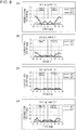
- Fig. 8 illustrates simulation results for Examples 2A, 2B, 2C, and 2D, which are modifications of Example 2 illustrated in Fig. 4(B) .
- Each magnet has a facing surface with its radius of curvature R being 4.5 mm in Example 2A in Fig. 8(A) , being 6.0 mm in Example 2B in Fig. 8(B) , being 9.0 mm in Example 2C in Fig. (C), and being 12 mm in Example 2D in Fig. 8(D) .
Landscapes
- Physics & Mathematics (AREA)
- General Physics & Mathematics (AREA)
- Condensed Matter Physics & Semiconductors (AREA)
- Transmission And Conversion Of Sensor Element Output (AREA)
- Measurement Of Length, Angles, Or The Like Using Electric Or Magnetic Means (AREA)
Description
- The present invention relates to a position detection device that detects the relative positions and movement of a magnet and a detection unit having a magnetic sensor.
-
PTL 1 describes an invention relating to a position detection device. - The position detection device has a case accommodating a holder that moves to advance and retreat, and the holder is provided with two magnets that are arranged side by side in a moving direction. A detection unit is fixed to the case. The detection unit is provided with two magnetoresistive elements facing the magnets that move.
- The holder is urged by a compression coil spring in a direction in which the holder projects from the case. When a shaft integrally formed with the holder is pressed to move the case in a direction against the urging direction of the compression coil spring, the movement of the magnets is detected with the magnetoresistive elements and the moving position of the holder is calculated.
- PTL 1: Japanese Registered Utility Model No.
3191531 - Although
PTL 1 does not provide a detailed description of a method for detecting the position of the holder, in a typical position detection device of this type, the magnetoresistive elements detect a component (Bz) and a component (Bx) of the magnetic flux density of a leakage magnetic field generated by the two magnets, the component (Bz) being in a direction perpendicular to the direction in which the holder moves, the component (Bx) being in a direction parallel to the direction in which the holder moves, to calculate the moving position of the holder. For example, an arc tangent is computed from the detected value of the component (Bz) and the detected value of the component (Bx), and the position of the holder is determined from the computed value. - Here, the intensity of the leakage magnetic field from the magnets is affected by temperature, and a demagnetization phenomenon in which the magnetic flux density of the leakage magnetic field decreases occurs at a high temperature. It is conventionally recognized that the rate at which the magnetic flux density decreases when a rectangular parallelepiped magnet is heated is always in the same proportion for the component (Bz) in the direction perpendicular to a magnetized surface and the component (Bx) in the direction parallel to the magnetized surface.
- On the basis of this recognition, it is considered that an arc tangent is computed on the basis of detected values obtained from the magnetoresistive elements at room temperature and a correction is made on a circuit so as to ensure linearity in the computed value, which makes it possible to ensure linearity of computed values when the holder is moved even if a temperature change occurs.
- In an actual position detection device, however, a problem arises in that, in a high-temperature environment, the value of the arc tangent computed on the basis of the output from the detection unit varies in accordance with a change in position facing the magnetized surfaces of the magnets and it is difficult to ensure linear position detection.
- The present invention is intended to address the conventional problem described above, and it is an object of the present invention to provide a position detection device having a structure that makes it easy to ensure the linearity of detection values for detecting the relative movement of a magnet and a detection unit even when a temperature change causes demagnetization of the magnet.
- The present invention provides a position detection device including a detection unit and a magnet facing the detection unit, the detection unit and the magnet being movable relatively to each other,
wherein the magnet is magnetized in a direction perpendicular to a relative movement trajectory of the detection unit, and the detection unit includes a magnetic sensor that detects a component of magnetic flux emerging from the magnet that is parallel to the movement trajectory, and a magnetic sensor that detects a component of the magnetic flux that is perpendicular to the movement trajectory, and
wherein the magnet has a facing surface facing the movement trajectory, and both ends of the facing surface in a direction extending along the movement trajectory are positioned farther away from the movement trajectory than a center portion of the facing surface. - In the position detection device according to the present invention, for example, the facing surface is a projecting curved surface having a curvature in a direction extending along the movement trajectory.
- In this case, preferably, the curvature has a radius that is greater than or equal to 1.7 times and less than or equal to 3.4 times a shortest distance between the facing surface and the movement trajectory.
- The position detection device according to the present invention can be configured such that a plurality of the magnets are disposed along the movement trajectory and the facing surfaces of adjacent magnets among the magnets are magnetized to opposite polarities.
- In the position detection device according to the present invention, the movement trajectory is a straight line. Alternatively, the movement trajectory is an arc of a circle.
- In the present invention, attention is focused on differences in demagnetizing factor for the magnetic flux density of a magnetic field generated by a magnet due to a temperature change between a direction perpendicular to a magnetized surface of the magnet and a direction parallel to the magnetized surface, and the magnetized surface, that is, a surface facing a detection unit, has a shape such that both ends thereof in a direction extending along a relative movement trajectory of the detection unit are positioned more rearward than a center portion thereof. This can reduce the difference in demagnetizing factor due to a temperature change between a component of the magnetic flux density in a direction perpendicular to the movement trajectory and a component of the magnetic flux density in a direction parallel to the movement trajectory and can ensure linearity for detection outputs from the detection unit even if a temperature change occurs.
-
- [
Fig. 1] Fig. 1(A) is an explanatory diagram illustrating a position detection device according to a first embodiment of the present invention, andFig. 1(B) is an explanatory diagram illustrating a conventional position detection device, - [
Fig. 2] Fig. 2 is an explanatory diagram illustrating a position detection device according to a second embodiment of the present invention, - [
Fig. 3] Figs. 3(A) and 3(B) are explanatory diagrams illustrating position detection devices according to third and fourth embodiments of the present invention, - [
Fig. 4] Figs. 4(A), 4(B), and 4(C) are explanatory diagrams of Example 1, Example 2, and Example 3, - [
Fig. 5] Figs. 5(A), 5(B), and 5(C) are explanatory diagrams of Comparative Example 1, Comparative Example 2, and Comparative Example 3, - [
Fig. 6] Figs. 6(A), 6(B), and 6(C) are charts illustrating variations in the computed value of an arc tangent caused by demagnetization in Example 1, Example 2, and Example 3, - [
Fig. 7] Figs. 7(A), 7(B), and 7(C) are charts illustrating variations in the computed value of an arc tangent caused by demagnetization in Comparative Example 1, Comparative Example 2, and Comparative Example 3, and - [
Fig. 8] Figs. 8(A), 8(B), 8(C), and 8(D) are charts illustrating variations in the computed value of an arc tangent caused by demagnetization in Example 2A, Example 2B, Example 2C, and Example 2D, which are modifications of Example 2, -
Fig. 1(A) schematically illustrates the structure of aposition detection device 1 according to a first embodiment of the present invention. - The
position detection device 1 includes amovement unit 10. Themovement unit 10 is provided with a movement unit (not illustrated) that linearly reciprocates in the X direction, and afirst magnet 11 and asecond magnet 12 are mounted on the movement unit. Theposition detection device 1 is provided with adetection unit 20, and themovement unit 10 and thedetection unit 20 face each other in the Z direction. - Since the
movement unit 10 moves in the X direction together with thefirst magnet 11 and thesecond magnet 12, the relative movement trajectory of themovement unit 10 and thedetection unit 20 is indicated by Tx inFig. 1(A) . Theposition detection device 1 according to the present invention may have a structure in which thefirst magnet 11 and thesecond magnet 12 stop, whereas thedetection unit 20 moves. In this case, the relative movement trajectory of themagnets detection unit 20 is also Tx. - In
Fig. 1(A) , thedetection unit 20 faces the middle of thefirst magnet 11 and thesecond magnet 12 in the X direction, and thefirst magnet 11 and thesecond magnet 12 move to the right or left in the X direction from a neutral position illustrated inFig. 1(A) . Alternatively, the movement unit of themovement unit 10 may be urged leftward in the X direction by an urging member such as a compression coil spring and stop at an initial position. When the movement unit is pressed to the right inFig. 1(A) , themagnets - The
first magnet 11 has a facingsurface 11a that faces the movement trajectory Tx, arear surface 11b opposite the facingsurface 11a, and bothside surfaces surface 11a is part of a cylindrical surface having a curvature in the X direction. An opposing distance between the center of the facingsurface 11a in the X direction and the movement trajectory Tx is indicated by δa. Further, an opposing distance between an end of the facingsurface 11a on theside surface 11c side and the movement trajectory Tx is indicated by δc, and an opposing distance between an end of the facingsurface 11a on theside surface 11d side and the movement trajectory Tx is indicated by δd. δc and δd have the same length, and δc and δd are longer than δa. That is, the facingsurface 11a has a shape such that both ends thereof in the X direction extending along the movement trajectory Tx are positioned farther away from the movement trajectory Tx than a center portion thereof. - The
rear surface 11b of thefirst magnet 11 is a flat surface that is parallel to the movement trajectory Tx and that is perpendicular to the plane ofFig. 1(A) . Theside surface 11c and theside surface 11d are flat surfaces that are perpendicular to the movement trajectory Tx and that is perpendicular to the plane ofFig. 1(A) . - The
first magnet 11 is magnetized in the Z direction, which is a direction perpendicular to the movement trajectory Tx, and the facingsurface 11a and therear surface 11b are magnetized surfaces having opposite polarities. The facingsurface 11a is magnetized to the N pole, and therear surface 11b is magnetized to the S pole. - The
first magnet 11 and thesecond magnet 12 have the same size and shape. Thesecond magnet 12 also has a facingsurface 12a, arear surface 12b, andside surfaces first magnet 11. The opposing distances δa, δc, and δd between the facingsurface 12a and the movement trajectory Tx are also the same as those of thefirst magnet 11. - The
second magnet 12 is also magnetized in the Z direction, and the facingsurface 12a and therear surface 12b are magnetized surfaces. It is to be noted that the direction of magnetization of thesecond magnet 12 is reversed to the direction of magnetization of thefirst magnet 11 by 180 degrees, that is, the facingsurface 12a is magnetized to the S pole and therear surface 12b is magnetized to the N pole. - The
detection unit 20 has at least two magnetic sensors. A first magnetic sensor has an axis of sensitivity Sx directed parallel to the movement trajectory Tx and is capable of detecting a magnetic flux density in a direction parallel to the movement trajectory Tx. A second magnetic sensor has an axis of sensitivity Sz directed perpendicular to the movement trajectory Tx and is capable of detecting a magnetic flux density in a direction perpendicular to the movement trajectory Tx. The magnetic sensors are each constituted by a Hall element, a magnetoresistance effect element, or the like. - The outputs from the first magnetic sensor and the second magnetic sensor of the
detection unit 20 are detected by adetection circuit 2, and each output is subjected to A/D conversion and is provided to acomputation unit 3. Thecomputation unit 3 is constituted by a CPU, a memory, and so on. -
Fig. 1(B) illustrates a conventionalposition detection device 101 for comparison and describing the detection operation of theposition detection device 1 according to the present invention. - The
position detection device 101 includes afirst magnet 111 and a second 112, each of which has a cubic shape, with a facingsurface 111a and a facingsurface 112a being both flat surfaces that are parallel to the movement trajectory Tx and that are vertical to the plane ofFig. 1(B) . Arear surface 111b and arear surface 112b are flat surfaces that are parallel to the facingsurface 111a and the facingsurface 112. - Both the
first magnet 111 and thesecond magnet 112 are magnetized in the Z direction. The facingsurface 111a of thefirst magnet 111 is magnetized to the N pole, and the facingsurface 112a of thesecond magnet 112 is magnetized to the S pole. An opposing distance δa between the facingsurfaces surfaces magnets Fig. 1(A) . - In the
position detection device 1 illustrated inFig. 1(A) , a magnetic field H extending from the facingsurface 11a of thefirst magnet 11 to the facingsurface 12a of thesecond magnet 12 is formed. Also in theposition detection device 101 illustrated inFig. 1(B) , a magnetic field H extending from the facingsurface 111a of thefirst magnet 111 to the facingsurface 112a of thesecond magnet 112 is formed. InFigs. 1(A) and 1(B) , magnetic lines of force that generate the magnetic field H are indicated by broken lines. - When the
detection unit 20 relatively moves along the movement trajectory Tx within the magnetic field H, the detection output of the first magnetic sensor having the axis of sensitivity Sx and the detection output of the second magnetic sensor having the axis of sensitivity Sz, which are included in thedetection unit 20, exhibit waveforms that are similar to a sine curve and a cosine curve. Thecomputation unit 3 computes an arc tangent from changing outputs that are similar to a sine curve and a cosine curve. The computed value of the arc tangent changes substantially linearly, which enables the measurement of the relative movement positions of themovement unit 10 and thedetection unit 20. - It is known that each magnet is subjected to demagnetization in which a generated magnetic field decreases when the temperature of the magnet becomes high. The present invention has been made focusing on a difference between demagnetizing factors for a component (Bx) and a component (Bz) of the magnetic flux density of a magnetic field emerging from a magnet, which occurs when the temperature of the magnet becomes high, with the component (Bx) being directed in the X direction and the component (Bz) being directed in the Z direction. As described below with reference to Examples and Comparative Examples, the difference between the demagnetizing factor for the component (Bx) and the demagnetizing factor for the component (Bz) at a high temperature gradually increases toward either end of each of the facing
surfaces 111a and 1112a in the X direction from the center portions thereof. - For this reason, in a high-temperature environment, an error of the calculated value of the arc tangent, which is computed from the ratio of the sine curve and the cosine curve by the
computation unit 3, increases as the facing position of thedetection unit 20 becomes closer to the vicinity of either end of each of themagnets detection unit 20 decreases. - In the
position detection device 1 according to an embodiment of the present invention, accordingly, as illustrated inFig. 1(A) , the facingsurfaces magnets - In the
position detection device 1 illustrated inFig. 1(A) , for example, when thedetection unit 20 reaches a position facing the front of theside surface 11d of thefirst magnet 11, the opposing distance δd between the facingsurface 11a and the movement trajectory Tx becomes large. As a result, the sensitivity of the component (Bz) of the magnetic flux density in the Z direction, which is detected by thedetection unit 20, becomes lower than that when thedetection unit 20 faces the center of the facingsurface 11a. The rate of decrease of the component (Bz) is greater than the rate of decrease of the sensitivity of the component (Bx) of the magnetic flux density in the X direction when thedetection unit 20 faces the front of theside surface 11d. - In addition, the facing
surface 11a is an inclined curved surface that gradually inclines away from the movement trajectory Tx toward theside surface 11d from the center portion thereof. Thus, the magnetic field H directed from the facingsurface 11a of thefirst magnet 11 to the facingsurface 12a of thesecond magnet 12 tends to be inclined in the X direction toward the right end of the facingsurface 11a. This also makes the rate of decrease of the sensitivity of the component (Bz) of the magnetic flux density in the Z direction greater than the rate of decrease of the sensitivity of the component (Bx) in the X direction when thedetection unit 20 faces the front of theside surface 11d. - As a result, when the magnet is subjected to high temperature and the component (Bx) of the magnetic flux density in the X direction in front of the
side surface 11d attenuates, the component (Bz) of the magnetic flux density in the Z direction, which is detected by thedetection unit 20, can be decreased accordingly in accordance with the shape of the facingsurface 11a. Thus, the calculated value of the arc tangent, which is computed on the basis of the ratio of the detection output of the first magnetic sensor having the axis of sensitivity Sx and the detection output of the second magnetic sensor having the axis of sensitivity Sz, which are detected by thedetection unit 20, can maintain linearity when thedetection unit 20 faces the center portion of each of the facingsurfaces detection unit 20 faces either end of each of the facingsurfaces - To this end, the facing
surfaces magnets surfaces -
Fig. 2 illustrates aposition detection device 1A according to a second embodiment of the present invention. - A
first magnet 11 and asecond magnet 12 that are used in theposition detection device 1A are the same as those in theposition detection device 1 illustrated inFig. 1(A) . In theposition detection device 1A illustrated inFig. 2 , amovement unit 10 having themagnets movement unit 10 and adetection unit 20 extends along an arc of a circle. Also in theposition detection device 1A, themagnets detection unit 20 may move along the arc-shaped movement trajectory Tx. - In the
position detection device 1A illustrated inFig. 2 , the opposing distances δc and δd between both ends of each of therespective facing surfaces magnets -
Fig. 3(A) illustrates aposition detection device 1B according to a third embodiment of the present invention. Amagnet 11B used in theposition detection device 1B has a facingsurface 11a that is constituted by a flat portion (i) in a center portion thereof, which is parallel to the movement trajectory Tx, and inclined flat portions (ii) on both sides of the flat portion (i). -
Fig. 3(B) illustrates aposition detection device 1C according to a fourth embodiment of the present invention. Amagnet 11C used in theposition detection device 1C has a facingsurface 11a that is constituted by a projecting curved surface portion (iii) in a center portion thereof and inclined flat portions (ii) on both sides of the projecting curved surface portion (iii). - Also in the
position detection devices detection unit 20 relatively moves along the movement trajectory Tx, the linearity error for detection outputs can be reduced. - A position detection device according to the present invention may include only one magnet, as illustrated in
Fig. 4(A) , or three or more magnets, as illustrated inFig. 4(C) . -
Fig. 4(A) illustrates Example 1, in which asingle magnet 11 faces the relative movement trajectory Tx of thedetection unit 20.Fig. 4(B) illustrates Example 2, in which twomagnets detection unit 20.Fig. 4(C) illustrates Example 3, in which threemagnets detection unit 20. - The
magnets surfaces -
Fig. 5(A) illustrates Comparative Example 1, in which asingle magnet 111 faces the relative movement trajectory Tx of thedetection unit 20.Fig. 5(B) illustrates Comparative Example 2, in which twomagnets detection unit 20.Fig. 5(C) illustrates Comparative Example 3, in which threemagnets detection unit 20. - The
magnets surfaces - The
magnets magnets - The
magnets magnets surfaces magnets magnets magnets - In Example 2 in
Fig. 4(B) and Comparative Example 2 inFig. 5(B) , an inter-magnet distance S1 is 17 mm, and in Example 3 inFig. 4(C) and Comparative Example 3 inFig. 5(C) , an inter-magnet distance S2 is 18 mm. -
Figs. 6(A), 6(B), and 6(C) illustrate the moving position of thedetection unit 20 and the linearity error for outputs of thedetection unit 20 in the respective Examples.Figs. 7(A), 7(B), and 7(C) illustrate the moving position of thedetection unit 20 and the linearity error for outputs of thedetection unit 20 in the respective Comparative Examples. - In
Fig. 6 andFig. 7 , the horizontal axis represents the relative positions of each magnet and thedetection unit 20 along the movement trajectory Tx. -
Fig. 6(A) illustrates simulation results of Example 1, and the origin "0" of the horizontal axis indicates that, as illustrated inFig. 4(A) , thedetection unit 20 is positioned to face the center of themagnet 11.Fig. 6(B) illustrates measurement results of Example 2, and the origin "0" of the horizontal axis indicates that, as illustrated inFig. 4(B) , thedetection unit 20 is positioned in the middle of the twomagnets Fig. 6(C) illustrates measurement results of Example 3, and the origin "0" of the horizontal axis indicates that, as illustrated inFig. 4(C) , thedetection unit 20 is positioned to face the center of themiddle magnet 11. -
Fig. 7(A) illustrates measurement results of Comparative Example 1, and the origin "0" of the horizontal axis indicates that, as illustrated inFig. 5(A) , thedetection unit 20 is positioned to face the center of themagnet 111.Fig. 7(B) illustrates measurement results of Comparative Example 2, and the origin "0" of the horizontal axis indicates that, as illustrated inFig. 5(B) , thedetection unit 20 is positioned in the middle of the twomagnets Fig. 7(C) illustrates measurement results of Comparative Example 3, and the origin "0" of the horizontal axis indicates that, as illustrated inFig. 5(C) , thedetection unit 20 is positioned to face the center of themiddle magnet 111. - In
Figs. 6(A), 6(B), and 6(C) andFigs. 7(A), 7(B), and 7(C) , the characteristics at an environmental temperature of 150 °C are indicated by solid lines, and the characteristics at an environmental temperature of -40 °C are indicated by broken lines. - In
Fig. 6 andFig. 7 , the vertical axis represents an error of the calculated value of the arc tangent (ATAN) computed on the basis of the detection output of the first magnetic sensor having the axis of sensitivity Sx and the detection output of the second magnetic sensor having the axis of sensitivity Sz, which are included in thedetection unit 20. That is, the difference (deg) between the calculated value of the arc tangent (ATAN) at a room temperature of 20 °C and the calculated value of the arc tangent (ATAN) at 150 °C is indicated by a solid line, and the difference (deg) between the calculated value of the arc tangent (ATAN) at a room temperature of 20 °C and the calculated value of the arc tangent (ATAN) at -40 °C is indicated by a broken line. - In the respective Comparative Examples in
Fig. 7 , it is seen that, in a high-temperature environment, the error of the calculated value of the arc tangent is large when thedetection unit 20 faces either end of a magnet, which results in linearity of position detection being impaired. In contrast, in the respective Examples inFig. 8 , it is seen that an error can be suppressed and linearity is improved. - In
Fig. 6(A) andFig. 7(A) , it is assumed that the amount of relative movement of thedetection unit 20 is in a range of ±3.5 mm. In this case, in Comparative Example 1 illustrated inFig. 7(A) , the difference (deg) in the calculated value (ATAN) is 0.24 deg, whereas in Example 1 illustrated inFig. 6(A) , the difference (deg) in the calculated value (ATAN) is about 0.03 deg. - In
Fig. 6(B) andFig. 7(B) , it is assumed that the amount of relative movement of thedetection unit 20 is in a range of ±7.5 mm. In this case, in Comparative Example 2 illustrated inFig. 7(B) , the difference (deg) in the calculated value (ATAN) is 0.21 deg, whereas in Example 2 illustrated inFig. 7(B) , the difference (deg) in the calculated value (ATAN) is 0.06 deg. - In
Fig. 6(C) andFig. 7(C) , it is assumed that the amount of relative movement of thedetection unit 20 is in a range of ±17 mm. In this case, in Comparative Example 3 illustrated inFig. 7(C) , the difference (deg) in the calculated value (ATAN) is 0.25 deg, whereas in Example 3 illustrated inFig. 6(C) , the difference (deg) in the calculated value (ATAN) is 0.07 deg. -
Fig. 8 illustrates simulation results for Examples 2A, 2B, 2C, and 2D, which are modifications of Example 2 illustrated inFig. 4(B) . Each magnet has a facing surface with its radius of curvature R being 4.5 mm in Example 2A inFig. 8(A) , being 6.0 mm in Example 2B inFig. 8(B) , being 9.0 mm in Example 2C in Fig. (C), and being 12 mm in Example 2D inFig. 8(D) . - In Examples 2A, 2B, 2C, and 2D, linearity of calculated values of the arc tangent is improved, compared with Comparative Example 2 illustrated in
Fig. 7 . It is to be noted that the effect of improving linearity of calculated values is very high when R is from the range of 6.0 mm to the range of 12 mm. Since the distance between the facing surface of each magnet and the movement trajectory Tx is 3.55 mm, the R/δa ratio is preferably in a range greater than or equal to 1.7 and less than or equal to 3.4. -
- 1, 1A, 1B, 1C position detection device
- 10 movement unit
- 11 first magnet
- 11a facing surface
- 12 second magnet
- 12a facing surface
- 13 magnet
- 13a facing surface
- 20 detection unit
- 111, 112, 113 magnet
- 111a, 112a, 113a facing surface
Claims (6)
- A position detection device comprising a detection unit and a magnet facing the detection unit, the detection unit and the magnet being movable relatively to each other,
wherein the magnet is magnetized in a direction perpendicular to a relative movement trajectory of the detection unit, and the detection unit includes a magnetic sensor that detects a component of magnetic flux emerging from the magnet that is parallel to the movement trajectory, and a magnetic sensor that detects a component of the magnetic flux that is perpendicular to the movement trajectory, and
wherein the magnet has a facing surface facing the movement trajectory, and both ends of the facing surface in a direction extending along the movement trajectory are positioned farther away from the movement trajectory than a center portion of the facing surface. - The position detection device according to Claim 1, wherein the facing surface is a projecting curved surface having a curvature in a direction extending along the movement trajectory.
- The position detection device according to Claim 1 or 2, wherein the curvature has a radius that is greater than or equal to 1.7 times and less than or equal to 3.4 times a shortest distance between the facing surface and the movement trajectory.
- The position detection device according to any one of Claims 1 to 3, wherein a plurality of the magnets are disposed along the movement trajectory, and the facing surfaces of adjacent magnets among the magnets are magnetized to opposite polarities.
- The position detection device according to any one of Claims 1 to 4, wherein the movement trajectory is a straight line.
- The position detection device according to any one of Claims 1 to 4, wherein the movement trajectory is an arc of a circle.
Applications Claiming Priority (2)
| Application Number | Priority Date | Filing Date | Title |
|---|---|---|---|
| JP2015211556 | 2015-10-28 | ||
| PCT/JP2016/074941 WO2017073151A1 (en) | 2015-10-28 | 2016-08-26 | Position detection device |
Publications (3)
| Publication Number | Publication Date |
|---|---|
| EP3370038A1 true EP3370038A1 (en) | 2018-09-05 |
| EP3370038A4 EP3370038A4 (en) | 2019-06-12 |
| EP3370038B1 EP3370038B1 (en) | 2020-06-17 |
Family
ID=58630325
Family Applications (1)
| Application Number | Title | Priority Date | Filing Date |
|---|---|---|---|
| EP16859388.7A Active EP3370038B1 (en) | 2015-10-28 | 2016-08-26 | Position detection device |
Country Status (6)
| Country | Link |
|---|---|
| US (1) | US20180216925A1 (en) |
| EP (1) | EP3370038B1 (en) |
| JP (1) | JP6492193B2 (en) |
| KR (1) | KR102042369B1 (en) |
| CN (1) | CN108351222B (en) |
| WO (1) | WO2017073151A1 (en) |
Families Citing this family (30)
| Publication number | Priority date | Publication date | Assignee | Title |
|---|---|---|---|---|
| CN105308947B (en) | 2013-06-13 | 2018-10-02 | 核心光电有限公司 | Dual Aperture Zoom Digital Video Camera |
| CN105359006B (en) | 2013-07-04 | 2018-06-22 | 核心光电有限公司 | Small Telephoto Lens Kit |
| EP3028443A2 (en) | 2013-08-01 | 2016-06-08 | Corephotonics Ltd. | Thin multi-aperture imaging system with auto-focus and methods for using same |
| US9392188B2 (en) | 2014-08-10 | 2016-07-12 | Corephotonics Ltd. | Zoom dual-aperture camera with folded lens |
| WO2016108093A1 (en) | 2015-01-03 | 2016-07-07 | Corephotonics Ltd. | Miniature telephoto lens module and a camera utilizing such a lens module |
| KR102078978B1 (en) | 2015-04-16 | 2020-02-19 | 코어포토닉스 리미티드 | Auto focus and optical imagestabilization in a compact folded camera |
| WO2017025822A1 (en) | 2015-08-13 | 2017-02-16 | Corephotonics Ltd. | Dual aperture zoom camera with video support and switching / non-switching dynamic control |
| EP3758356B1 (en) | 2016-05-30 | 2021-10-20 | Corephotonics Ltd. | Actuator |
| KR102657464B1 (en) | 2016-07-07 | 2024-04-12 | 코어포토닉스 리미티드 | Linear ball guided voice coil motor for folded optic |
| US11531209B2 (en) | 2016-12-28 | 2022-12-20 | Corephotonics Ltd. | Folded camera structure with an extended light-folding-element scanning range |
| EP4145206A1 (en) | 2017-01-12 | 2023-03-08 | Corephotonics Ltd. | Compact folded camera |
| WO2019049414A1 (en) * | 2017-09-07 | 2019-03-14 | 株式会社村田製作所 | Magnetic sensor and current sensor provided with same |
| JP6806919B2 (en) | 2017-11-23 | 2021-01-06 | コアフォトニクス リミテッド | Compact bendable camera structure |
| JP6954139B2 (en) * | 2018-01-16 | 2021-10-27 | 株式会社デンソー | Rotation angle detector |
| KR102781658B1 (en) | 2018-04-23 | 2025-03-13 | 코어포토닉스 리미티드 | An optical-path folding-element with an extended two degree of freedom rotation range |
| US11287081B2 (en) | 2019-01-07 | 2022-03-29 | Corephotonics Ltd. | Rotation mechanism with sliding joint |
| CN121284176A (en) | 2019-07-31 | 2026-01-06 | 核心光电有限公司 | System for creating background blur in camera panning or motion |
| EP4509897A3 (en) | 2019-12-03 | 2025-05-14 | Corephotonics Ltd. | Actuators for providing an extended two-degree of freedom rotation range |
| US11949976B2 (en) | 2019-12-09 | 2024-04-02 | Corephotonics Ltd. | Systems and methods for obtaining a smart panoramic image |
| US12007668B2 (en) | 2020-02-22 | 2024-06-11 | Corephotonics Ltd. | Split screen feature for macro photography |
| JP6824484B1 (en) * | 2020-03-10 | 2021-02-03 | 三菱電機株式会社 | Magnetic linear position detector |
| WO2021234515A1 (en) | 2020-05-17 | 2021-11-25 | Corephotonics Ltd. | Image stitching in the presence of a full field of view reference image |
| CN117572549A (en) | 2020-05-30 | 2024-02-20 | 核心光电有限公司 | Systems and methods for obtaining ultra-macro images |
| US11637977B2 (en) | 2020-07-15 | 2023-04-25 | Corephotonics Ltd. | Image sensors and sensing methods to obtain time-of-flight and phase detection information |
| EP4045960B1 (en) | 2020-07-15 | 2024-12-04 | Corephotonics Ltd. | Point of view aberrations correction in a scanning folded camera |
| CN114270145B (en) * | 2020-07-31 | 2024-05-17 | 核心光电有限公司 | Hall sensor-magnet geometry for long-travel linear position sensing |
| CN116626960A (en) | 2020-08-12 | 2023-08-22 | 核心光电有限公司 | Methods for Optical Image Stabilization |
| KR20250165686A (en) | 2021-03-11 | 2025-11-26 | 코어포토닉스 리미티드 | Systems for pop-out camera |
| JP7507729B2 (en) | 2021-06-21 | 2024-06-28 | Tdk株式会社 | Magnetic sensor and brake system and steering system using the magnetic sensor |
| KR20250028500A (en) | 2022-03-24 | 2025-02-28 | 코어포토닉스 리미티드 | Slim compact lens optical image stabilization |
Family Cites Families (14)
| Publication number | Priority date | Publication date | Assignee | Title |
|---|---|---|---|---|
| US708895A (en) * | 1901-11-27 | 1902-09-09 | William J Martin | Furniture-caster. |
| JP3191531B2 (en) | 1993-10-20 | 2001-07-23 | ミノルタ株式会社 | Image forming device |
| JP3419533B2 (en) * | 1994-03-07 | 2003-06-23 | 帝人製機株式会社 | Magnetic scale and magnetic detection device having the same |
| JP3597733B2 (en) * | 1999-08-09 | 2004-12-08 | アルプス電気株式会社 | Magnetic displacement detector |
| US6577123B2 (en) * | 2001-06-04 | 2003-06-10 | Delphi Technologies, Inc. | Linear position sensor assembly |
| US6653830B2 (en) * | 2001-12-14 | 2003-11-25 | Wabash Technologies, Inc. | Magnetic position sensor having shaped pole pieces to provide a magnetic field having a varying magnetic flux density field strength |
| DE10202320A1 (en) * | 2002-01-23 | 2003-07-31 | Bosch Gmbh Robert | Displacement sensor with magnetoelectric transducer element |
| DE10334869B3 (en) * | 2003-07-29 | 2004-09-16 | Tech3 E.K. | Rotation angle sensor has a rotating shaft with attached permanent magnets, with angular measurements based on both axial displacement of the shaft and sinusoidal and cosinusoidal signals generated by it |
| US7088095B1 (en) * | 2004-02-04 | 2006-08-08 | Honeywell International Inc. | Balanced magnetic linear displacement sensor |
| JP4787601B2 (en) * | 2005-11-08 | 2011-10-05 | 株式会社東海理化電機製作所 | Position detection device |
| DE112009000299A5 (en) * | 2008-04-02 | 2011-03-03 | Polycontact Ag | Magnetic linear sensor arrangement |
| JP4985730B2 (en) * | 2009-01-29 | 2012-07-25 | 株式会社デンソー | Stroke sensor and rotation angle sensor |
| JP5408508B2 (en) * | 2011-11-01 | 2014-02-05 | 株式会社デンソー | Position detection device |
| CN203178236U (en) * | 2013-02-07 | 2013-09-04 | 中国石油天然气股份有限公司 | A New Sensor for Flux Leakage Detection |
-
2016
- 2016-08-26 JP JP2017547653A patent/JP6492193B2/en active Active
- 2016-08-26 EP EP16859388.7A patent/EP3370038B1/en active Active
- 2016-08-26 WO PCT/JP2016/074941 patent/WO2017073151A1/en not_active Ceased
- 2016-08-26 KR KR1020187011042A patent/KR102042369B1/en active Active
- 2016-08-26 CN CN201680061505.6A patent/CN108351222B/en active Active
-
2018
- 2018-03-29 US US15/939,418 patent/US20180216925A1/en not_active Abandoned
Also Published As
| Publication number | Publication date |
|---|---|
| EP3370038A4 (en) | 2019-06-12 |
| KR102042369B1 (en) | 2019-11-07 |
| US20180216925A1 (en) | 2018-08-02 |
| EP3370038B1 (en) | 2020-06-17 |
| CN108351222A (en) | 2018-07-31 |
| JPWO2017073151A1 (en) | 2018-07-26 |
| CN108351222B (en) | 2020-10-30 |
| JP6492193B2 (en) | 2019-03-27 |
| WO2017073151A1 (en) | 2017-05-04 |
| KR20180056712A (en) | 2018-05-29 |
Similar Documents
| Publication | Publication Date | Title |
|---|---|---|
| EP3370038B1 (en) | Position detection device | |
| JP5079816B2 (en) | Preferably a magnetic position sensor having a magnet shape that varies pseudo-sinusoidally. | |
| US9618318B2 (en) | Method for contactlessly measuring a relative position by means of a 3D hall sensor having measurement signal store | |
| US7977935B2 (en) | Temperature tolerant magnetic linear displacement sensor | |
| EP1711779A1 (en) | Balanced magnetic linear displacement sensor | |
| CN106643467B (en) | Rotation angle detection device and angle sensor unit used for the same | |
| US20150145506A1 (en) | Magnetic sensor | |
| EP2657651A3 (en) | Position sensor | |
| US8829896B2 (en) | Stroke amount detecting device | |
| JP5500389B2 (en) | Stroke amount detection device | |
| US9562791B2 (en) | Measurement system of the relative position between two separate structural parts | |
| CN106461418A (en) | Magnetic position detection device | |
| JP2017049127A (en) | Magnetic field detection device and rotation detection device | |
| JP4787601B2 (en) | Position detection device | |
| JP5958294B2 (en) | Stroke sensor | |
| US9068817B2 (en) | Location detector device | |
| US9638547B2 (en) | Selective slope linear position sensor | |
| WO2023058356A1 (en) | Position detecting device | |
| JP2016212070A (en) | Moving object detection device | |
| JP2023151543A (en) | Position detection system, sensor unit, magnetic sensor and sensor block | |
| JP2014098654A (en) | Stroke sensor | |
| JP2016151486A (en) | Distance measurement device | |
| JP2016223946A (en) | Moving object detector |
Legal Events
| Date | Code | Title | Description |
|---|---|---|---|
| STAA | Information on the status of an ep patent application or granted ep patent |
Free format text: STATUS: THE INTERNATIONAL PUBLICATION HAS BEEN MADE |
|
| PUAI | Public reference made under article 153(3) epc to a published international application that has entered the european phase |
Free format text: ORIGINAL CODE: 0009012 |
|
| STAA | Information on the status of an ep patent application or granted ep patent |
Free format text: STATUS: REQUEST FOR EXAMINATION WAS MADE |
|
| 17P | Request for examination filed |
Effective date: 20180329 |
|
| AK | Designated contracting states |
Kind code of ref document: A1 Designated state(s): AL AT BE BG CH CY CZ DE DK EE ES FI FR GB GR HR HU IE IS IT LI LT LU LV MC MK MT NL NO PL PT RO RS SE SI SK SM TR |
|
| AX | Request for extension of the european patent |
Extension state: BA ME |
|
| DAV | Request for validation of the european patent (deleted) | ||
| DAX | Request for extension of the european patent (deleted) | ||
| RAP1 | Party data changed (applicant data changed or rights of an application transferred) |
Owner name: ALPS ALPINE CO., LTD. |
|
| REG | Reference to a national code |
Ref country code: DE Ref legal event code: R079 Ref document number: 602016038481 Country of ref document: DE Free format text: PREVIOUS MAIN CLASS: G01D0005140000 Ipc: G01D0003036000 |
|
| A4 | Supplementary search report drawn up and despatched |
Effective date: 20190510 |
|
| RIC1 | Information provided on ipc code assigned before grant |
Ipc: G01B 5/00 20060101ALI20190506BHEP Ipc: G01D 3/036 20060101AFI20190506BHEP Ipc: G01R 33/09 20060101ALI20190506BHEP Ipc: G01D 5/18 20060101ALI20190506BHEP Ipc: G01D 5/14 20060101ALI20190506BHEP Ipc: G01R 33/02 20060101ALI20190506BHEP Ipc: G01B 7/00 20060101ALI20190506BHEP |
|
| GRAP | Despatch of communication of intention to grant a patent |
Free format text: ORIGINAL CODE: EPIDOSNIGR1 |
|
| STAA | Information on the status of an ep patent application or granted ep patent |
Free format text: STATUS: GRANT OF PATENT IS INTENDED |
|
| INTG | Intention to grant announced |
Effective date: 20200116 |
|
| GRAS | Grant fee paid |
Free format text: ORIGINAL CODE: EPIDOSNIGR3 |
|
| GRAA | (expected) grant |
Free format text: ORIGINAL CODE: 0009210 |
|
| STAA | Information on the status of an ep patent application or granted ep patent |
Free format text: STATUS: THE PATENT HAS BEEN GRANTED |
|
| AK | Designated contracting states |
Kind code of ref document: B1 Designated state(s): AL AT BE BG CH CY CZ DE DK EE ES FI FR GB GR HR HU IE IS IT LI LT LU LV MC MK MT NL NO PL PT RO RS SE SI SK SM TR |
|
| REG | Reference to a national code |
Ref country code: GB Ref legal event code: FG4D |
|
| REG | Reference to a national code |
Ref country code: CH Ref legal event code: EP |
|
| REG | Reference to a national code |
Ref country code: IE Ref legal event code: FG4D |
|
| REG | Reference to a national code |
Ref country code: DE Ref legal event code: R096 Ref document number: 602016038481 Country of ref document: DE |
|
| REG | Reference to a national code |
Ref country code: AT Ref legal event code: REF Ref document number: 1281852 Country of ref document: AT Kind code of ref document: T Effective date: 20200715 |
|
| PG25 | Lapsed in a contracting state [announced via postgrant information from national office to epo] |
Ref country code: LT Free format text: LAPSE BECAUSE OF FAILURE TO SUBMIT A TRANSLATION OF THE DESCRIPTION OR TO PAY THE FEE WITHIN THE PRESCRIBED TIME-LIMIT Effective date: 20200617 Ref country code: SE Free format text: LAPSE BECAUSE OF FAILURE TO SUBMIT A TRANSLATION OF THE DESCRIPTION OR TO PAY THE FEE WITHIN THE PRESCRIBED TIME-LIMIT Effective date: 20200617 Ref country code: NO Free format text: LAPSE BECAUSE OF FAILURE TO SUBMIT A TRANSLATION OF THE DESCRIPTION OR TO PAY THE FEE WITHIN THE PRESCRIBED TIME-LIMIT Effective date: 20200917 Ref country code: GR Free format text: LAPSE BECAUSE OF FAILURE TO SUBMIT A TRANSLATION OF THE DESCRIPTION OR TO PAY THE FEE WITHIN THE PRESCRIBED TIME-LIMIT Effective date: 20200918 Ref country code: FI Free format text: LAPSE BECAUSE OF FAILURE TO SUBMIT A TRANSLATION OF THE DESCRIPTION OR TO PAY THE FEE WITHIN THE PRESCRIBED TIME-LIMIT Effective date: 20200617 |
|
| PGFP | Annual fee paid to national office [announced via postgrant information from national office to epo] |
Ref country code: FR Payment date: 20200821 Year of fee payment: 5 |
|
| REG | Reference to a national code |
Ref country code: LT Ref legal event code: MG4D |
|
| REG | Reference to a national code |
Ref country code: NL Ref legal event code: MP Effective date: 20200617 |
|
| PG25 | Lapsed in a contracting state [announced via postgrant information from national office to epo] |
Ref country code: LV Free format text: LAPSE BECAUSE OF FAILURE TO SUBMIT A TRANSLATION OF THE DESCRIPTION OR TO PAY THE FEE WITHIN THE PRESCRIBED TIME-LIMIT Effective date: 20200617 Ref country code: HR Free format text: LAPSE BECAUSE OF FAILURE TO SUBMIT A TRANSLATION OF THE DESCRIPTION OR TO PAY THE FEE WITHIN THE PRESCRIBED TIME-LIMIT Effective date: 20200617 Ref country code: BG Free format text: LAPSE BECAUSE OF FAILURE TO SUBMIT A TRANSLATION OF THE DESCRIPTION OR TO PAY THE FEE WITHIN THE PRESCRIBED TIME-LIMIT Effective date: 20200917 Ref country code: RS Free format text: LAPSE BECAUSE OF FAILURE TO SUBMIT A TRANSLATION OF THE DESCRIPTION OR TO PAY THE FEE WITHIN THE PRESCRIBED TIME-LIMIT Effective date: 20200617 |
|
| REG | Reference to a national code |
Ref country code: AT Ref legal event code: MK05 Ref document number: 1281852 Country of ref document: AT Kind code of ref document: T Effective date: 20200617 |
|
| PG25 | Lapsed in a contracting state [announced via postgrant information from national office to epo] |
Ref country code: NL Free format text: LAPSE BECAUSE OF FAILURE TO SUBMIT A TRANSLATION OF THE DESCRIPTION OR TO PAY THE FEE WITHIN THE PRESCRIBED TIME-LIMIT Effective date: 20200617 Ref country code: AL Free format text: LAPSE BECAUSE OF FAILURE TO SUBMIT A TRANSLATION OF THE DESCRIPTION OR TO PAY THE FEE WITHIN THE PRESCRIBED TIME-LIMIT Effective date: 20200617 |
|
| PG25 | Lapsed in a contracting state [announced via postgrant information from national office to epo] |
Ref country code: CZ Free format text: LAPSE BECAUSE OF FAILURE TO SUBMIT A TRANSLATION OF THE DESCRIPTION OR TO PAY THE FEE WITHIN THE PRESCRIBED TIME-LIMIT Effective date: 20200617 Ref country code: RO Free format text: LAPSE BECAUSE OF FAILURE TO SUBMIT A TRANSLATION OF THE DESCRIPTION OR TO PAY THE FEE WITHIN THE PRESCRIBED TIME-LIMIT Effective date: 20200617 Ref country code: ES Free format text: LAPSE BECAUSE OF FAILURE TO SUBMIT A TRANSLATION OF THE DESCRIPTION OR TO PAY THE FEE WITHIN THE PRESCRIBED TIME-LIMIT Effective date: 20200617 Ref country code: PT Free format text: LAPSE BECAUSE OF FAILURE TO SUBMIT A TRANSLATION OF THE DESCRIPTION OR TO PAY THE FEE WITHIN THE PRESCRIBED TIME-LIMIT Effective date: 20201019 Ref country code: IT Free format text: LAPSE BECAUSE OF FAILURE TO SUBMIT A TRANSLATION OF THE DESCRIPTION OR TO PAY THE FEE WITHIN THE PRESCRIBED TIME-LIMIT Effective date: 20200617 Ref country code: SM Free format text: LAPSE BECAUSE OF FAILURE TO SUBMIT A TRANSLATION OF THE DESCRIPTION OR TO PAY THE FEE WITHIN THE PRESCRIBED TIME-LIMIT Effective date: 20200617 Ref country code: AT Free format text: LAPSE BECAUSE OF FAILURE TO SUBMIT A TRANSLATION OF THE DESCRIPTION OR TO PAY THE FEE WITHIN THE PRESCRIBED TIME-LIMIT Effective date: 20200617 Ref country code: EE Free format text: LAPSE BECAUSE OF FAILURE TO SUBMIT A TRANSLATION OF THE DESCRIPTION OR TO PAY THE FEE WITHIN THE PRESCRIBED TIME-LIMIT Effective date: 20200617 |
|
| PG25 | Lapsed in a contracting state [announced via postgrant information from national office to epo] |
Ref country code: PL Free format text: LAPSE BECAUSE OF FAILURE TO SUBMIT A TRANSLATION OF THE DESCRIPTION OR TO PAY THE FEE WITHIN THE PRESCRIBED TIME-LIMIT Effective date: 20200617 Ref country code: SK Free format text: LAPSE BECAUSE OF FAILURE TO SUBMIT A TRANSLATION OF THE DESCRIPTION OR TO PAY THE FEE WITHIN THE PRESCRIBED TIME-LIMIT Effective date: 20200617 Ref country code: IS Free format text: LAPSE BECAUSE OF FAILURE TO SUBMIT A TRANSLATION OF THE DESCRIPTION OR TO PAY THE FEE WITHIN THE PRESCRIBED TIME-LIMIT Effective date: 20201017 |
|
| REG | Reference to a national code |
Ref country code: DE Ref legal event code: R097 Ref document number: 602016038481 Country of ref document: DE |
|
| PG25 | Lapsed in a contracting state [announced via postgrant information from national office to epo] |
Ref country code: MC Free format text: LAPSE BECAUSE OF FAILURE TO SUBMIT A TRANSLATION OF THE DESCRIPTION OR TO PAY THE FEE WITHIN THE PRESCRIBED TIME-LIMIT Effective date: 20200617 |
|
| REG | Reference to a national code |
Ref country code: CH Ref legal event code: PL |
|
| PLBE | No opposition filed within time limit |
Free format text: ORIGINAL CODE: 0009261 |
|
| STAA | Information on the status of an ep patent application or granted ep patent |
Free format text: STATUS: NO OPPOSITION FILED WITHIN TIME LIMIT |
|
| PG25 | Lapsed in a contracting state [announced via postgrant information from national office to epo] |
Ref country code: LU Free format text: LAPSE BECAUSE OF NON-PAYMENT OF DUE FEES Effective date: 20200826 Ref country code: DK Free format text: LAPSE BECAUSE OF FAILURE TO SUBMIT A TRANSLATION OF THE DESCRIPTION OR TO PAY THE FEE WITHIN THE PRESCRIBED TIME-LIMIT Effective date: 20200617 Ref country code: CH Free format text: LAPSE BECAUSE OF NON-PAYMENT OF DUE FEES Effective date: 20200831 Ref country code: LI Free format text: LAPSE BECAUSE OF NON-PAYMENT OF DUE FEES Effective date: 20200831 |
|
| 26N | No opposition filed |
Effective date: 20210318 |
|
| GBPC | Gb: european patent ceased through non-payment of renewal fee |
Effective date: 20200917 |
|
| REG | Reference to a national code |
Ref country code: BE Ref legal event code: MM Effective date: 20200831 |
|
| PG25 | Lapsed in a contracting state [announced via postgrant information from national office to epo] |
Ref country code: SI Free format text: LAPSE BECAUSE OF FAILURE TO SUBMIT A TRANSLATION OF THE DESCRIPTION OR TO PAY THE FEE WITHIN THE PRESCRIBED TIME-LIMIT Effective date: 20200617 |
|
| PG25 | Lapsed in a contracting state [announced via postgrant information from national office to epo] |
Ref country code: IE Free format text: LAPSE BECAUSE OF NON-PAYMENT OF DUE FEES Effective date: 20200826 Ref country code: GB Free format text: LAPSE BECAUSE OF NON-PAYMENT OF DUE FEES Effective date: 20200917 Ref country code: BE Free format text: LAPSE BECAUSE OF NON-PAYMENT OF DUE FEES Effective date: 20200831 |
|
| PG25 | Lapsed in a contracting state [announced via postgrant information from national office to epo] |
Ref country code: TR Free format text: LAPSE BECAUSE OF FAILURE TO SUBMIT A TRANSLATION OF THE DESCRIPTION OR TO PAY THE FEE WITHIN THE PRESCRIBED TIME-LIMIT Effective date: 20200617 Ref country code: MT Free format text: LAPSE BECAUSE OF FAILURE TO SUBMIT A TRANSLATION OF THE DESCRIPTION OR TO PAY THE FEE WITHIN THE PRESCRIBED TIME-LIMIT Effective date: 20200617 Ref country code: CY Free format text: LAPSE BECAUSE OF FAILURE TO SUBMIT A TRANSLATION OF THE DESCRIPTION OR TO PAY THE FEE WITHIN THE PRESCRIBED TIME-LIMIT Effective date: 20200617 |
|
| PG25 | Lapsed in a contracting state [announced via postgrant information from national office to epo] |
Ref country code: MK Free format text: LAPSE BECAUSE OF FAILURE TO SUBMIT A TRANSLATION OF THE DESCRIPTION OR TO PAY THE FEE WITHIN THE PRESCRIBED TIME-LIMIT Effective date: 20200617 |
|
| PG25 | Lapsed in a contracting state [announced via postgrant information from national office to epo] |
Ref country code: FR Free format text: LAPSE BECAUSE OF NON-PAYMENT OF DUE FEES Effective date: 20210831 |
|
| PGFP | Annual fee paid to national office [announced via postgrant information from national office to epo] |
Ref country code: DE Payment date: 20250820 Year of fee payment: 10 |