JP4985730B2 - Stroke sensor and rotation angle sensor - Google Patents
Stroke sensor and rotation angle sensor Download PDFInfo
- Publication number
- JP4985730B2 JP4985730B2 JP2009195255A JP2009195255A JP4985730B2 JP 4985730 B2 JP4985730 B2 JP 4985730B2 JP 2009195255 A JP2009195255 A JP 2009195255A JP 2009195255 A JP2009195255 A JP 2009195255A JP 4985730 B2 JP4985730 B2 JP 4985730B2
- Authority
- JP
- Japan
- Prior art keywords
- magnetic
- magnetic sensitive
- electrical output
- magnetic sensing
- combination
- Prior art date
- Legal status (The legal status is an assumption and is not a legal conclusion. Google has not performed a legal analysis and makes no representation as to the accuracy of the status listed.)
- Active
Links
Images


Classifications
-
- G—PHYSICS
- G01—MEASURING; TESTING
- G01D—MEASURING NOT SPECIALLY ADAPTED FOR A SPECIFIC VARIABLE; ARRANGEMENTS FOR MEASURING TWO OR MORE VARIABLES NOT COVERED IN A SINGLE OTHER SUBCLASS; TARIFF METERING APPARATUS; MEASURING OR TESTING NOT OTHERWISE PROVIDED FOR
- G01D5/00—Mechanical means for transferring the output of a sensing member; Means for converting the output of a sensing member to another variable where the form or nature of the sensing member does not constrain the means for converting; Transducers not specially adapted for a specific variable
- G01D5/12—Mechanical means for transferring the output of a sensing member; Means for converting the output of a sensing member to another variable where the form or nature of the sensing member does not constrain the means for converting; Transducers not specially adapted for a specific variable using electric or magnetic means
- G01D5/14—Mechanical means for transferring the output of a sensing member; Means for converting the output of a sensing member to another variable where the form or nature of the sensing member does not constrain the means for converting; Transducers not specially adapted for a specific variable using electric or magnetic means influencing the magnitude of a current or voltage
- G01D5/142—Mechanical means for transferring the output of a sensing member; Means for converting the output of a sensing member to another variable where the form or nature of the sensing member does not constrain the means for converting; Transducers not specially adapted for a specific variable using electric or magnetic means influencing the magnitude of a current or voltage using Hall-effect devices
- G01D5/145—Mechanical means for transferring the output of a sensing member; Means for converting the output of a sensing member to another variable where the form or nature of the sensing member does not constrain the means for converting; Transducers not specially adapted for a specific variable using electric or magnetic means influencing the magnitude of a current or voltage using Hall-effect devices influenced by the relative movement between the Hall device and magnetic fields
-
- F—MECHANICAL ENGINEERING; LIGHTING; HEATING; WEAPONS; BLASTING
- F02—COMBUSTION ENGINES; HOT-GAS OR COMBUSTION-PRODUCT ENGINE PLANTS
- F02D—CONTROLLING COMBUSTION ENGINES
- F02D41/00—Electrical control of supply of combustible mixture or its constituents
- F02D41/009—Electrical control of supply of combustible mixture or its constituents using means for generating position or synchronisation signals
-
- G—PHYSICS
- G01—MEASURING; TESTING
- G01D—MEASURING NOT SPECIALLY ADAPTED FOR A SPECIFIC VARIABLE; ARRANGEMENTS FOR MEASURING TWO OR MORE VARIABLES NOT COVERED IN A SINGLE OTHER SUBCLASS; TARIFF METERING APPARATUS; MEASURING OR TESTING NOT OTHERWISE PROVIDED FOR
- G01D2205/00—Indexing scheme relating to details of means for transferring or converting the output of a sensing member
- G01D2205/20—Detecting rotary movement
- G01D2205/22—Detecting rotary movement by converting the rotary movement into a linear movement
-
- G—PHYSICS
- G01—MEASURING; TESTING
- G01D—MEASURING NOT SPECIALLY ADAPTED FOR A SPECIFIC VARIABLE; ARRANGEMENTS FOR MEASURING TWO OR MORE VARIABLES NOT COVERED IN A SINGLE OTHER SUBCLASS; TARIFF METERING APPARATUS; MEASURING OR TESTING NOT OTHERWISE PROVIDED FOR
- G01D2205/00—Indexing scheme relating to details of means for transferring or converting the output of a sensing member
- G01D2205/20—Detecting rotary movement
- G01D2205/26—Details of encoders or position sensors specially adapted to detect rotation beyond a full turn of 360°, e.g. multi-rotation
Description
本発明は、直線的に変位する被検出体の直線的な変位量を検出するストロークセンサ、および回転する被検出体の回転角を検出する回転角センサに関する(以下、「直線的な変位量」をストローク量と呼ぶ)。 The present invention relates to a stroke sensor that detects a linear displacement amount of a detected object that is linearly displaced, and a rotation angle sensor that detects a rotation angle of a rotating detected object (hereinafter referred to as “linear displacement amount”). Is called stroke amount).
従来から、例えば、車両の各種制御には、ストロークセンサや回転角センサからの出力値が多数利用されており、制御上、重要な位置を占めるようになっている。
ストロークセンサは、例えば、磁束を形成するとともに被検出体の直線的な変位に応じて直線的に変位する可動子と、磁束密度を検出し、電気的出力に変換して出力する固定子とを備える。また、回転角センサは、例えば、磁束を形成するとともに被検出体の回転に応じて回転する可動子と、磁束密度を検出し、電気的出力に変換して出力する固定子とを備える。
Conventionally, for example, many output values from a stroke sensor and a rotation angle sensor have been used for various types of vehicle control, and occupy important positions for control.
The stroke sensor includes, for example, a mover that forms a magnetic flux and linearly displaces according to the linear displacement of the detected object, and a stator that detects the magnetic flux density, converts it into an electrical output, and outputs it. Prepare. The rotation angle sensor includes, for example, a mover that forms a magnetic flux and rotates according to the rotation of the detection target, and a stator that detects the magnetic flux density, converts it into an electrical output, and outputs it.
そして、ストロークセンサや回転角センサは、それぞれの固定子から出力される電気的出力に基づいてそれぞれの出力値を算出し、電子制御装置(ECU)は、これらの出力値に基づいて被検出体のストローク量や回転角を把握して各種の制御処理を実行する。 The stroke sensor and the rotation angle sensor calculate respective output values based on the electrical outputs output from the respective stators, and the electronic control unit (ECU) detects the detected object based on these output values. Various control processes are executed by grasping the stroke amount and rotation angle.
ところで、可動子により形成される磁束や固定子から出力される電気的出力は、温度に応じて変動するので、これらの温度特性に基づく限界以上に、ストロークセンサや回転角センサの検出精度を高めることができない。
このため、ストロークセンサでは、ストローク量と出力値との相関が理想的なリニア特性にならず、回転角センサでも、回転角と出力値との相関が理想的なリニア特性にならない。
By the way, the magnetic output formed by the mover and the electrical output output from the stator fluctuate depending on the temperature. Therefore, the detection accuracy of the stroke sensor and the rotation angle sensor is increased beyond the limit based on these temperature characteristics. I can't.
For this reason, the correlation between the stroke amount and the output value is not an ideal linear characteristic in the stroke sensor, and the correlation between the rotation angle and the output value is not an ideal linear characteristic even in the rotation angle sensor.
なお、極性の異なる2つの磁石により磁束を形成し、さらに別の2つの磁石により逆向きの磁束を形成して、ゼロを跨ぐプラス、マイナスの両側に出力値を得ることができるポジションセンサが開示されている(例えば、特許文献1参照)。しかし、このポジションセンサでも、磁束や電気的出力が温度に応じて変動することに変わりはなく、検出精度は、温度特性に基づく限界以上に高くならない。また、磁石が直線的に変位しながら回転すると、検出される磁束密度が変動するため、磁石の回転に伴うストローク量の検出誤差が大きい。 In addition, a position sensor is disclosed in which a magnetic flux is formed by two magnets with different polarities, and a magnetic flux in the opposite direction is formed by another two magnets, and output values can be obtained on both the positive and negative sides across zero. (For example, refer to Patent Document 1). However, even in this position sensor, the magnetic flux and the electrical output still vary according to the temperature, and the detection accuracy does not become higher than the limit based on the temperature characteristics. Further, when the magnet rotates while linearly displacing, the detected magnetic flux density fluctuates, so that the stroke amount detection error associated with the rotation of the magnet is large.
本発明は、上記の問題点を解決するためになされたものであり、その目的は、磁束や電気的出力が温度に応じて変動しても、ストローク量や回転角に関して精度の高い出力値を得ることにある。また、磁石が直線的に変位しながら回転しても、ストローク量の検出誤差を抑制できるようにすることにある。 The present invention has been made to solve the above-described problems, and its purpose is to provide a highly accurate output value with respect to the stroke amount and the rotation angle even when the magnetic flux and the electrical output fluctuate depending on the temperature. There is to get. Another object of the present invention is to suppress a stroke amount detection error even if the magnet rotates while being linearly displaced.
〔請求項1の手段〕
請求項1に記載のストロークセンサは、直線的に変位する被検出体の直線的な変位量(ストローク量)を検出するものであり、自身の長手方向と垂直な方向に着磁される磁石と、長手方向と平行に配列され、磁石により形成される磁束に感磁してそれぞれ電気的出力を発生する2つの感磁部とを備える。
[Means of Claim 1]
The stroke sensor according to
そして、2つの感磁部は、それぞれの感磁面が互いに同一の面方向となるように配される。また、磁石は、被検出体の直線的な変位に応じて、2つの感磁部に対し長手方向に相対的に変位するとともに、2つの感磁部が並ぶ配列軸と着磁方向に向かい合う感磁部対向周縁を有する。そして、感磁部対向周縁は、配列軸上の磁束密度と配列軸の座標との相関が正弦曲線に略一致するように曲線状に設けられている。 The two magnetic sensitive portions are arranged such that the respective magnetic sensitive surfaces are in the same plane direction. In addition, the magnet is displaced relative to the two magnetic sensing portions in the longitudinal direction in accordance with the linear displacement of the detection object, and the magnet facing the arrangement axis where the two magnetic sensing portions are arranged. It has a magnetic part opposing periphery. The periphery of the magnetism sensitive part is provided in a curved shape so that the correlation between the magnetic flux density on the array axis and the coordinates of the array axis substantially matches the sine curve.
これにより、磁石のストローク量と2つの感磁部の内の一方の感磁部の電気的出力に基づき算出される磁束密度との相関、および、磁石のストローク量と他方の感磁部の電気的出力に基づき算出される磁束密度との相関は、周期が同一であって互いに位相が異なる2つの正弦曲線になる。また、2つの正弦曲線の位相差は、2つの感磁部間の距離に応じて算出することができる。 Accordingly, the correlation between the magnet stroke amount and the magnetic flux density calculated based on the electrical output of one of the two magnetosensitive portions, and the magnet stroke amount and the electric power of the other magnetosensitive portion. The correlation with the magnetic flux density calculated based on the target output is two sinusoidal curves having the same period and different phases. Further, the phase difference between the two sinusoids can be calculated according to the distance between the two magnetic sensing portions.
したがって、一方の感磁部から得られる電気的出力をオフセット調整して得られる数値と、他方の感磁部から得られる電気的出力をオフセット調整して得られる数値との差および和を求め、差を和で除することにより、磁束の温度特性や電気的出力の温度特性をキャンセルすることができるとともに、除算により得た数値から、磁石のストローク量を変数とする正接に相当する数値を得ることができる。この結果、得られた正接を逆三角関数処理することで、磁石のストローク量と逆三角関数処理により得られた数値との相関を、磁束の温度特性や電気的出力の温度特性の影響を受けない理想的なリニア特性とすることができる。 Thus, obtaining a difference and sum of the numerical values obtained by the offset adjusting an electrical output obtained an electrical output obtained from the hand of the sensitive portion and the numerical values obtained by adjusting the offset, from the other sensitive portion By dividing the difference by the sum, the temperature characteristic of magnetic flux and the temperature characteristic of electrical output can be canceled, and the numerical value corresponding to the tangent with the stroke amount of the magnet as a variable can be obtained from the numerical value obtained by division. Obtainable. As a result, by processing the obtained tangent with an inverse trigonometric function, the correlation between the stroke amount of the magnet and the numerical value obtained by the inverse trigonometric function is affected by the temperature characteristics of magnetic flux and electrical output. There can be no ideal linear characteristics.
以上により、磁束や電気的出力が温度に応じて変動しても、ストローク量に関して精度の高い出力値を得ることができる。
また、磁石が直線的に変位しながら回転しても、2つの感磁部がそれぞれ感磁する磁束密度は同じ比率で変動する。このため、磁石の回転に伴うストローク量の検出誤差を抑制することができる。
なお、上記のように、配列軸上の磁束密度と配列軸の座標との相関が正弦曲線に略一致するような感磁部対向周縁の形状とは、例えば、円弧、楕円弧のような二次曲線の一部等であり、配列軸に向かって凸状に突出していてもよく、配列軸に対し凹状に窪んでいてもよい。
As described above, even if the magnetic flux and the electrical output fluctuate depending on the temperature, it is possible to obtain a highly accurate output value regarding the stroke amount.
Further, even if the magnet rotates while linearly displacing, the magnetic flux densities at which the two magnetic sensing parts sense each fluctuate at the same ratio. For this reason, the detection error of the stroke amount accompanying rotation of a magnet can be suppressed.
Note that, as described above, the shape of the peripheral edge facing the magnetic sensing portion so that the correlation between the magnetic flux density on the array axis and the coordinates of the array axis substantially coincides with the sinusoid is, for example, a secondary such as an arc or an elliptical arc. It may be a part of a curve, or may protrude in a convex shape toward the arrangement axis, or may be recessed in a concave shape with respect to the arrangement axis.
さらに、ストロークセンサは、磁石の感磁部対向周縁と同一形状の感磁部対向周縁を有する別磁石を備える。そして、別磁石は、自身の感磁部対向周縁側の極性が磁石の感磁部対向周縁側の極性と逆になるように着磁され、自身の感磁部対向周縁が配列軸を挟んで磁石の感磁部対向周縁と鏡映対称をなすように、磁石とともに2つの感磁部に対し相対的に変位する。Further, the stroke sensor includes a separate magnet having a magnetic sensing portion facing peripheral edge having the same shape as the magnetic sensing portion facing peripheral edge of the magnet. The other magnet is magnetized so that the polarity on the side opposite to the magnetic sensing part of the magnet is opposite to the polarity on the side facing the magnetic sensing part of the magnet, and the circumference on the opposite side of the magnetic sensing part sandwiches the arrangement axis. The magnet is displaced relative to the two magnetosensitive portions together with the magnet so as to be mirror-symmetrical with the magnetosensitive portion facing peripheral edge of the magnet.
これにより、位置ずれに対するロバスト性を高めることができる。 Thereby, the robustness with respect to position shift can be improved.
〔請求項2の手段〕
請求項2に記載のストロークセンサによれば、2つの感磁部は、正弦曲線の周期の1/4の距離だけ離れて配列軸上に配列されている。
これにより、一方の感磁部から得られる電気的出力に基づく正弦曲線、および、他方の感磁部から得られる電気的出力に基づく正弦曲線は、同一周期かつ位相差が周期の1/4になる。このため、一方の感磁部から得られる電気的出力に基づく正弦曲線を、磁石のストローク量を変数とする正弦関数とみなせば、他方の感磁部から得られる電気的出力に基づく正弦曲線を、磁石のストローク量を変数とする余弦関数に変換することができる。
したがって、一方の感磁部から得られる電気的出力をオフセット調整して得られる数値を、他方の感磁部から得られる電気的出力をオフセット調整して得られる数値で除することにより、磁石のストローク量を変数とする正接に相当する数値を得ることができる。また、磁束の温度特性や電気的出力の温度特性を、除算によりキャンセルすることができる。この結果、得られた正接を逆三角関数処理することで、磁石のストローク量と逆三角関数処理により得られた数値との相関を、磁束の温度特性や電気的出力の温度特性の影響を受けない理想的なリニア特性とすることができる。
以上により、より簡便な数式を用いてストローク量に関する出力値を算出することができるので、ストローク量の検出に関して演算負荷を下げることができる。
[Means of claim 2]
According to the stroke sensor of the second aspect, the two magnetic sensitive portions are arranged on the arrangement axis with a distance of 1/4 of the period of the sine curve.
As a result, the sine curve based on the electrical output obtained from one magnetic sensing part and the sine curve based on the electrical output obtained from the other magnetic sensitive part have the same period and the phase difference is ¼ of the period. Become. For this reason, if the sine curve based on the electrical output obtained from one magnetic sensing part is regarded as a sine function with the stroke amount of the magnet as a variable, the sine curve based on the electrical output obtained from the other magnetic sensing part is obtained. The cosine function with the stroke amount of the magnet as a variable can be converted.
Therefore, by dividing the numerical value obtained by offset adjustment of the electrical output obtained from one magnetic sensitive part by the numerical value obtained by offset adjustment of the electrical output obtained from the other magnetic sensitive part, A numerical value corresponding to the tangent with the stroke amount as a variable can be obtained. Further, the temperature characteristic of the magnetic flux and the temperature characteristic of the electrical output can be canceled by division. As a result, by processing the obtained tangent with an inverse trigonometric function, the correlation between the stroke amount of the magnet and the numerical value obtained by the inverse trigonometric function is affected by the temperature characteristics of magnetic flux and electrical output. There can be no ideal linear characteristics.
As described above, since the output value related to the stroke amount can be calculated using a simpler mathematical expression, it is possible to reduce the calculation load regarding the detection of the stroke amount.
〔請求項3の手段〕
請求項3に記載のストロークセンサによれば、2つの感磁部とは別の感磁部が、2つの感磁部の内の少なくとも一方の感磁部と配列軸上で略同一の位置に配され、別の感磁部の感磁面は、一方の感磁部の感磁面と非平行である。そして、被検出体は直線的に変位するとともに回転し、磁石および別磁石は、2つの感磁部および別の感磁部に対し長手方向に相対的に変位するとともに、被検出体の回転に応じて、2つの感磁部および別の感磁部に対し相対的に回転する。
[Means of claim 3]
According to the stroke sensor of
これにより、磁石の回転角と一方の感磁部の電気的出力に基づき算出される磁束密度との相関、および、磁石の回転角と別の感磁部の電気的出力に基づき算出される磁束密度との相関は、周期が同一であって互いに位相が異なる2つの正弦曲線になる。また、2つの正弦曲線の位相差は、一方の感磁部の感磁面と別の感磁部の感磁面とが形成する角度に応じて算出することができる。 Accordingly, the correlation between the rotation angle of the magnet and the magnetic flux density calculated based on the electrical output of one of the magnetic sensing parts, and the magnetic flux calculated based on the rotation angle of the magnet and the electrical output of another magnetic sensing part. The correlation with the density is two sinusoids having the same period and different phases. Further, the phase difference between the two sinusoids can be calculated according to the angle formed by the magnetic sensitive surface of one magnetic sensitive portion and the magnetic sensitive surface of another magnetic sensitive portion.
したがって、一方の感磁部から得られる電気的出力をオフセット調整して得られる数値と、別の感磁部から得られる電気的出力をオフセット調整して得られる数値との差および和を求め、差を和で除することにより、磁束の温度特性や電気的出力の温度特性をキャンセルすることができるとともに、除算により得た数値から、磁石の回転角を変数とする正接に相当する数値を得ることができる。この結果、得られた正接を逆三角関数処理することで、磁石の回転角と逆三角関数処理により得られた数値との相関を、磁束の温度特性や電気的出力の温度特性の影響を受けない理想的なリニア特性とすることができる。 Thus, obtaining a difference and sum of the numerical value obtained by adjusting the offset of the electrical output obtained, a numerical value obtained by offset adjustment electrical output obtained from another sensitive portion from hand of sensitive portion By dividing the difference by the sum, the temperature characteristic of magnetic flux and the temperature characteristic of electrical output can be canceled, and the numerical value corresponding to the tangent with the rotation angle of the magnet as a variable can be obtained from the numerical value obtained by division. Obtainable. As a result, by processing the obtained tangent with an inverse trigonometric function, the correlation between the rotation angle of the magnet and the numerical value obtained by the inverse trigonometric function is affected by the temperature characteristics of the magnetic flux and the electrical output. There can be no ideal linear characteristics.
以上により、磁束や電気的出力が温度に応じて変動しても、ストローク量および回転角の両方に関して精度の高い出力値を得ることができる。このため、1つのセンサでストローク量および回転角の両方に関して精度の高い検出が可能になるので、精度の向上と同時に搭載性の向上およびコスト低減を達成することができる。 As described above, even if the magnetic flux and the electrical output fluctuate depending on the temperature, it is possible to obtain a highly accurate output value with respect to both the stroke amount and the rotation angle. For this reason, since it is possible to detect with high accuracy with respect to both the stroke amount and the rotation angle with one sensor, it is possible to improve the mounting accuracy and reduce the cost at the same time as improving the accuracy.
〔請求項4の手段〕
請求項4に記載のストロークセンサによれば、一方の感磁部の感磁面と、別の感磁部の感磁面とは、90°の角度をなす。
これにより、一方の感磁部から得られる電気的出力に基づく正弦曲線、および、別の感磁部から得られる電気的出力に基づく正弦曲線は、同一周期かつ位相差が90°になる。このため、一方の感磁部から得られる電気的出力に基づく正弦曲線を、磁石の回転角を変数とする正弦関数とみなせば、別の感磁部から得られる電気的出力に基づく正弦曲線を、磁石の回転角を変数とする余弦関数に変換することができる。
したがって、一方の感磁部から得られる電気的出力をオフセット調整して得られる数値を、別の感磁部から得られる電気的出力をオフセット調整して得られる数値で除することにより、磁石の回転角を変数とする正接に相当する数値を得ることができる。また、磁束の温度特性や電気的出力の温度特性を、除算によりキャンセルすることができる。この結果、得られた正接を逆三角関数処理することで、磁石の回転角と逆三角関数処理により得られた数値との相関を、磁束の温度特性や電気的出力の温度特性の影響を受けない理想的なリニア特性とすることができる。
以上により、より簡便な数式を用いて回転角に関する出力値を算出することができるので、回転角の検出に関して演算負荷を下げることができる。
[Means of claim 4]
According to the stroke sensor of the fourth aspect, the magnetic sensitive surface of one magnetic sensitive portion and the magnetic sensitive surface of another magnetic sensitive portion form an angle of 90 °.
Thereby, the sine curve based on the electrical output obtained from one magnetic sensing part and the sine curve based on the electrical output obtained from another magnetic sensitive part have the same period and a phase difference of 90 °. For this reason, if a sine curve based on the electrical output obtained from one magnetic sensing part is regarded as a sine function with the rotation angle of the magnet as a variable, a sine curve based on the electrical output obtained from another magnetic sensing part is obtained. The cosine function with the rotation angle of the magnet as a variable can be converted.
Therefore, by dividing the numerical value obtained by offset adjustment of the electrical output obtained from one magnetic sensitive part by the numerical value obtained by offset adjustment of the electrical output obtained from another magnetic sensitive part, A numerical value corresponding to the tangent with the rotation angle as a variable can be obtained. Further, the temperature characteristic of the magnetic flux and the temperature characteristic of the electrical output can be canceled by division. As a result, by processing the obtained tangent with an inverse trigonometric function, the correlation between the rotation angle of the magnet and the numerical value obtained by the inverse trigonometric function is affected by the temperature characteristics of the magnetic flux and the electrical output. There can be no ideal linear characteristics.
As described above, since the output value related to the rotation angle can be calculated using a simpler mathematical expression, it is possible to reduce the calculation load regarding the detection of the rotation angle.
〔請求項5の手段〕
請求項5に記載のストロークセンサによれば、別の感磁部とはさらに別の感磁部が、2つの感磁部の内の他方の感磁部と配列軸上で略同一の位置に配されている。そして、さらに別の感磁部の感磁面は、他方の感磁部の感磁面と非平行、かつ、別の感磁部の感磁面と同一の面方向である。
これにより、ストローク量の検出に関して、一方の感磁部から得られる電気的出力と他方の感磁部から得られる電気的出力との組合せ(以下、第1組合せと呼ぶ)、または、別の感磁部から得られる電気的出力とさらに別の感磁部から得られる電気的出力との組合せ(以下、第3組合せと呼ぶ)のいずれか一方を選択して出力値を算出することができる。
そして、第1組合せを利用する場合、一方の感磁部から得られる電気的出力と他方の感磁部から得られる電気的出力とから、ストローク量を変数とする正接に相当する数値を求め、第3組合せを利用する場合、別の感磁部から得られる電気的出力とさらに別の感磁部から得られる電気的出力とから、ストローク量を変数とする正接に相当する数値を求める。
[Means of claim 5]
According to the stroke sensor of
Thereby, regarding the detection of the stroke amount, a combination of an electrical output obtained from one magnetic sensing part and an electrical output obtained from the other magnetic sensing part (hereinafter referred to as a first combination), or another feeling. An output value can be calculated by selecting any one of a combination of an electrical output obtained from the magnetic part and an electrical output obtained from another magnetic sensing part (hereinafter referred to as a third combination).
And when using the first combination, from the electrical output obtained from one magnetic sensing part and the electrical output obtained from the other magnetic sensing part, a numerical value corresponding to the tangent with the stroke amount as a variable is obtained, When the third combination is used, a numerical value corresponding to a tangent with a stroke amount as a variable is obtained from an electrical output obtained from another magnetic sensing part and an electrical output obtained from another magnetic sensing part.
また、回転角の検出に関して、一方の感磁部から得られる電気的出力と別の感磁部から得られる電気的出力との組合せ(以下、第2組合せと呼ぶ)、または、他方の感磁部から得られる電気的出力とさらに別の感磁部から得られる電気的出力との組合せ(以下、第4組合せと呼ぶ)のいずれか一方を選択して出力値を算出することができる。
そして、第2組合せを利用する場合、一方の感磁部から得られる電気的出力と別の感磁部から得られる電気的出力とから、回転角を変数とする正接に相当する数値を求め、第4組合せを利用する場合、他方の感磁部から得られる電気的出力とさらに別の感磁部から得られる電気的出力とから、回転角を変数とする正接に相当する数値を求める。
ここで、磁石と別磁石とにより形成される磁束は、配列軸上の磁束密度と配列軸の座標との相関が正弦曲線に略一致するような特異なものであることから、各々の感磁部が感磁する磁束密度は、ストローク量や回転角に応じて異なる。
In addition, regarding the detection of the rotation angle, a combination of an electrical output obtained from one magnetic sensing unit and an electrical output obtained from another magnetic sensing unit (hereinafter referred to as a second combination), or the other magnetic sensing The output value can be calculated by selecting any one of the combinations of the electrical output obtained from the part and the electrical output obtained from another magnetic sensing part (hereinafter referred to as the fourth combination).
Then, when using the second combination, a numerical value corresponding to a tangent with a rotation angle as a variable is obtained from an electrical output obtained from one magnetic sensing part and an electrical output obtained from another magnetic sensing part, When the fourth combination is used, a numerical value corresponding to a tangent with the rotation angle as a variable is obtained from the electrical output obtained from the other magnetic sensing part and the electrical output obtained from another magnetic sensing part.
Here, the magnetic flux formed by the magnet and the separate magnet is unique such that the correlation between the magnetic flux density on the array axis and the coordinates of the array axis substantially matches a sine curve. The magnetic flux density at which the part is magnetized varies depending on the stroke amount and the rotation angle.
このため、ストローク量を検出する際には、回転角を目安として、第1、第3組合せの内、感磁する磁束密度が大きい方の組合せを選択することで、出力値に対するS/N比を高めることができる。また、回転角を検出する際には、ストローク量を目安として、第2、第4組合せの内、感磁する磁束密度が大きい方の組合せを選択することで、出力値に対するS/N比を高めることができる。
以上により、ストローク量および回転角の両方に関して、さらに精度の高い出力値を得ることができる。
Therefore, when detecting the stroke amount, the S / N ratio with respect to the output value is selected by selecting the combination of the first and third combinations having the larger magnetic flux density to be sensed from the rotation angle as a guide. Can be increased. When detecting the rotation angle, the S / N ratio for the output value is selected by selecting the combination of the second and fourth combinations having the larger magnetic flux density to be sensed, using the stroke amount as a guide. Can be increased.
As described above, a more accurate output value can be obtained with respect to both the stroke amount and the rotation angle.
〔請求項6の手段〕
請求項6に記載のストロークセンサによれば、直線的な変位量の検出に関しては、回転角を目安として、第1組合せまたは第3組合せの内、感磁する磁束密度が大きい方の組合せを選択して利用し、回転角の検出に関しては、直線的な変位量を目安として、第2組合せまたは第4組合せの内、感磁する磁束密度が大きい方の組合せを選択して利用する。
[Means of claim 6 ]
According to the stroke sensor of the sixth aspect , with respect to detection of the linear displacement amount, the combination of the first combination or the third combination having the higher magnetic flux density to be detected is selected from the rotation angle as a guide. With regard to detection of the rotation angle, the combination of the second combination and the fourth combination having the higher magnetic flux density to be magnetized is selected and used with the linear displacement amount as a guide.
〔請求項7の手段〕
請求項7に記載のストロークセンサによれば、磁石は、感磁部対向周縁と着磁方向に反対側の周縁が磁性体により覆われている。
これにより、外乱磁場に対するロバスト性を高めることができる。
[Means of Claim 7 ]
According to the stroke sensor of the seventh aspect of the present invention, the magnet is covered with the magnetic material on the opposite side of the magnetism-facing peripheral edge and the magnetizing direction.
Thereby, the robustness with respect to a disturbance magnetic field can be improved.
〔請求項8の手段〕
請求項8に記載のストロークセンサによれば、別磁石は、感磁部対向周縁と着磁方向に反対側の周縁が磁性体により覆われている。
これにより、ストロークセンサが別磁石を備える場合にも、外乱磁場に対するロバスト性を高めることができる。
[Means of Claim 8 ]
According to the stroke sensor of the eighth aspect of the present invention, the separate magnet is covered with the magnetic body on the opposite side of the magnetizing portion-facing peripheral edge in the magnetization direction.
Thereby, also when a stroke sensor is provided with another magnet, robustness with respect to a disturbance magnetic field can be improved.
〔請求項9の手段〕
請求項9に記載のストロークセンサによれば、2つの感磁部は、それぞれホール素子であり、1つのチップで構成されている。
これにより、ストロークセンサの体格を小型化することができるとともに、2つの感磁部の性能、特性を、より同一にすることができる。
[Means of Claim 9 ]
According to the stroke sensor of the ninth aspect , each of the two magnetic sensitive portions is a Hall element and is constituted by one chip.
Thereby, the physique of a stroke sensor can be reduced in size, and the performance and characteristics of the two magnetic sensitive parts can be made more identical.
〔請求項10の手段〕
請求項10に記載のストロークセンサによれば、2つの感磁部、別の感磁部、およびさらに別の感磁部は、それぞれホール素子である。そして、2つの感磁部が1つのチップで構成され、別の感磁部とさらに別の感磁部とが1つのチップで構成されている。
これにより、ストロークセンサの体格を小型化することができる。また、2つの感磁部の性能、特性を、より同一にすることができるとともに、別の感磁部およびさらに別の感磁部の性能、特性を、より同一にすることができる。
[Means of Claim 10 ]
According to the stroke sensor of the tenth aspect , each of the two magnetic sensitive parts, another magnetic sensitive part, and still another magnetic sensitive part is a Hall element. Two magnetic sensing parts are constituted by one chip, and another magnetic sensing part and another magnetic sensing part are constituted by one chip.
Thereby, the physique of a stroke sensor can be reduced in size. In addition, the performance and characteristics of the two magnetic sensing parts can be made more identical, and the performance and characteristics of another magnetic sensing part and still another magnetic sensing part can be made more identical.
〔請求項11の手段〕
請求項11に記載のストロークセンサによれば、2つの感磁部、別の感磁部、およびさらに別の感磁部は、それぞれホール素子である。そして、2つの感磁部の内の一方の感磁部と別の感磁部とが1つのチップで構成され、2つの感磁部の内の他方の感磁部とさらに別の感磁部とが1つのチップで構成されている。
これにより、ストロークセンサの体格を小型化することができる。また、一方の感磁部および別の感磁部の性能、特性を、より同一にすることができるとともに、他方の感磁部およびさらに別の感磁部の性能、特性を、より同一にすることができる。
[Means of Claim 11 ]
According to the stroke sensor of the eleventh aspect , each of the two magnetic sensitive parts, another magnetic sensitive part, and still another magnetic sensitive part is a Hall element. One of the two magnetic sensing parts and the other magnetic sensing part are constituted by one chip, and the other of the two magnetic sensing parts and another magnetic sensing part. Are configured by one chip.
Thereby, the physique of a stroke sensor can be reduced in size. In addition, the performance and characteristics of one magnetic sensing part and another magnetic sensing part can be made more identical, and the performance and characteristics of the other magnetic sensing part and another magnetic sensing part can be made more identical. be able to.
〔請求項12の手段〕
請求項12に記載のストロークセンサによれば、磁石の長手方向の両端にはヨークが付着している。
この手段は、磁石を有する可動子の別態様を示すものである。
[Means of Claim 12 ]
According to the stroke sensor of the twelfth aspect , the yoke is attached to both ends in the longitudinal direction of the magnet.
This means shows another aspect of the mover having a magnet.
〔請求項13の手段〕
請求項13に記載のストロークセンサによれば、別磁石の長手方向の両端にはヨークが付着している。
この手段は、磁石および別磁石を有する可動子の別態様を示すものである。
[Means of Claim 13 ]
According to the stroke sensor of the thirteenth aspect , the yoke is attached to both ends of the other magnet in the longitudinal direction.
This means shows another aspect of the mover having a magnet and another magnet.
〔請求項14、15の手段〕
請求項14、15に記載の回転角センサは、回転する被検出体の回転角を検出するものである。そして、この回転角センサは、互いに、自身の長手方向が平行となるように、かつ長手方向と垂直な短手方向に対向するように配され、被検出体の回転に応じて回転する2つの磁石と、2つの磁石により短手方向に挟まれるように配される3つの感磁部と、2つの磁石の回転を直線的な変位に変換し、2つの磁石を長手方向に直線的に変位させる回転/ストローク変換機構とを備える。
[Means of
The rotation angle sensor according to
また、3つの感磁部の内、2つの感磁部は、互いに長手方向に関して同一の位置となるように、かつ、それぞれの感磁面が互いに非平行となるように配され、残り1つの感磁部は、2つの感磁部が配される位置を含み長手方向と平行に伸びる配列軸を想定したときに、配列軸上で2つの感磁部から離れて配されている。さらに、残り1つの感磁部の感磁面と、2つの感磁部の内の一方の感磁部の感磁面とは同一の面方向である。 Of the three magnetic sensing parts, the two magnetic sensing parts are arranged so that they are at the same position in the longitudinal direction, and the respective magnetic sensing surfaces are non-parallel to each other, and the remaining one The magnetic sensing part is arranged away from the two magnetic sensing parts on the arrangement axis, assuming an arrangement axis extending in parallel to the longitudinal direction including the position where the two magnetic sensing parts are arranged. Furthermore, the magnetosensitive surface of the remaining one magnetosensitive portion and the magnetosensitive surface of one of the two magnetosensitive portions are in the same plane direction.
また、それぞれの磁石の短手方向の両端周縁の内、3つの感磁部と向かい合う周縁を感磁部対向周縁と定義すると、2つの磁石は、それぞれの感磁部対向周縁が互いに逆の極性を有するように、それぞれ短手方向に着磁されて配されている。そして、それぞれの感磁部対向周縁は、配列軸上の磁束密度と配列軸の座標との相関が正弦曲線に略一致するように略同一の曲線状に設けられ、配列軸を挟んで互いに鏡映対称をなしている。 Further, if the peripheral edges facing the three magnetic sensing parts among the peripheral edges of each magnet in the short direction are defined as the magnetic sensitive part opposing peripheral edges, the two magnets have polarities opposite to each other. So as to be magnetized in the short direction. The respective peripheries of the magnetosensitive portions are provided in substantially the same curve shape so that the correlation between the magnetic flux density on the array axis and the coordinates of the array axis substantially matches the sine curve, and mirrors each other across the array axis. It is symmetrical.
そして、2つの磁石は、それぞれの感磁部対向周縁が互いに鏡映対称をなしながら、被検出体の回転に応じて、3つの感磁部に対し、相対的に長手方向に直線的に変位するとともに、相対的に回転する。 The two magnets are linearly displaced in the longitudinal direction relative to the three magnetic sensing parts according to the rotation of the detected object, while the opposite edges of the magnetic sensing parts are mirror-symmetric with each other. And rotate relatively.
これにより、回転角をストローク量に変換することができるので、回転角が360°を超える場合でも、回転角に関する出力値を回転角と1対1に対応させることができる。また、2つの感磁部の内の一方の感磁部から得られる電気的出力と、残り1つの感磁部から得られる電気的出力とを利用して出力値を算出することで、回転角の変換により生じるストローク量と出力値との相関を、請求項1〜請求項15の手段と同様に、磁束の温度特性や電気的出力の温度特性の影響を受けない理想的なリニア特性とすることができる。
Thereby, since the rotation angle can be converted into a stroke amount, even when the rotation angle exceeds 360 °, the output value related to the rotation angle can be made to correspond to the rotation angle on a one-to-one basis. Further, by calculating an output value using an electrical output obtained from one of the two magnetosensitive parts and an electrical output obtained from the remaining one of the magnetosensitive parts, the rotation angle is calculated. As in the means of
このため、磁束や電気的出力が温度に応じて変動しても、360°以上の回転角を高い精度で検出することができる。
なお、請求項14の手段によれば、一方の感磁部から得られる電気的出力をオフセット調整して得られる数値と、残り1つの感磁部から得られる電気的出力をオフセット調整して得られる数値との差および和を求め、差を和で除することにより、2つの磁石の回転を回転/ストローク変換機構により変換して得られるストローク量を変数とする正接に相当する数値を求める。
また、請求項15の手段によれば、一方の感磁部と残り1つの感磁部とが正弦曲線の周期の1/4の距離だけ離れて配列軸上に配列されている。そして、一方の感磁部から得られる電気的出力をオフセット調整して得られる数値を、残り1つの感磁部から得られる電気的出力をオフセット調整して得られる数値で除することにより、2つの磁石の回転を回転/ストローク変換機構により変換して得られるストローク量を変数とする正接に相当する数値を求める。
For this reason, even if the magnetic flux and the electrical output fluctuate according to the temperature, a rotation angle of 360 ° or more can be detected with high accuracy.
According to the means of
According to the fifteenth aspect of the present invention, one magnetic sensing portion and the remaining one magnetic sensing portion are arranged on the arrangement axis with a distance of 1/4 of the period of the sine curve. Then, by dividing the numerical value obtained by offset adjustment of the electrical output obtained from one of the magnetic sensitive parts by the numerical value obtained by offset adjustment of the electrical output obtained from the remaining one magnetic sensitive part, 2 A numerical value corresponding to a tangent with a stroke amount obtained by converting the rotation of two magnets by a rotation / stroke conversion mechanism as a variable is obtained.
〔請求項16、17の手段〕
請求項16、17に記載の回転角センサによれば、回転角を360°の整数倍の角度と360°以下の角度とに分け、360°の整数倍の角度を、2つの磁石の回転を回転/ストローク変換機構により変換して得られるストローク量に基づき検出するとともに、360°以下の角度を、2つの感磁部から得られるそれぞれの電気的出力を利用して検出する。
これにより、360°の整数倍の角度をストローク量から大まかに検出するとともに、360°以下の角度を、より高精度に検出することで、さらに回転角に関して精度の高い出力値を得ることができる。
[Means of
According to the rotation angle sensor of
As a result, an angle that is an integral multiple of 360 ° is roughly detected from the stroke amount, and an angle that is 360 ° or less is detected with higher accuracy, so that an output value that is more accurate with respect to the rotation angle can be obtained. .
すなわち、2つの感磁部の内の一方の感磁部から得られる電気的出力と、他方の感磁部から得られる電気的出力とを利用して360°以下の角度に関する出力値を算出することで、360°以下の角度に関する出力値と360°以下の角度との相関を、請求項3の手段と同様に、磁束の温度特性や電気的出力の温度特性の影響を受けない理想的なリニア特性とすることができる。このため、磁束や電気的出力が温度に応じて変動しても、360°以下の角度に関して精度の高い出力値を得ることができるので、さらに回転角に関して精度の高い出力値を得ることができる。 That is, an output value relating to an angle of 360 ° or less is calculated using an electrical output obtained from one of the two magnetosensitive parts and an electrical output obtained from the other magnetosensitive part. Therefore, the correlation between the output value relating to the angle of 360 ° or less and the angle of 360 ° or less is ideally influenced by the temperature characteristics of the magnetic flux and the electrical output. Linear characteristics can be obtained. For this reason, even if the magnetic flux and the electrical output fluctuate depending on the temperature, it is possible to obtain a highly accurate output value with respect to an angle of 360 ° or less, and it is possible to obtain a highly accurate output value with respect to the rotation angle. .
なお、回転角を360°の整数倍の角度と360°以下の角度とに分け、360°以下の角度に関して精度の高い出力値を得る方法は、ストローク量が短く回転角の分解能が粗くなってしまう場合に有効である。
また、請求項16の手段によれば、2つの感磁部の内の一方の感磁部から得られる電気的出力をオフセット調整して得られる数値と、他方の感磁部から得られる電気的出力をオフセット調整して得られる数値との差および和を求め、差を和で除することにより、360°以下の角度を変数とする正接に相当する数値を求める。
また、請求項17の手段によれば、2つの感磁部のそれぞれの感磁面が90°の角度をなしている。そして、2つの感磁部の内の一方の感磁部から得られる電気的出力をオフセット調整して得られる数値を、他方の感磁部から得られる電気的出力をオフセット調整して得られる数値で除することにより、360°以下の角度を変数とする正接に相当する数値を求める。
The method of obtaining a highly accurate output value for an angle of 360 ° or less by dividing the rotation angle into an angle that is an integral multiple of 360 ° and an angle of 360 ° or less results in a short stroke amount and coarse rotation angle resolution. This is effective when
According to the sixteenth aspect of the present invention, the numerical value obtained by offset adjustment of the electrical output obtained from one of the two magnetic sensitive parts and the electrical obtained from the other magnetic sensitive part A difference and a sum with a numerical value obtained by offset adjustment of the output are obtained, and a numerical value corresponding to a tangent having an angle of 360 ° or less as a variable is obtained by dividing the difference by the sum.
According to the seventeenth aspect, the magnetic sensitive surfaces of the two magnetic sensitive parts form an angle of 90 °. The numerical value obtained by offset adjustment of the electrical output obtained from one of the two magnetic sensitive parts, and the numerical value obtained by offset adjustment of the electrical output obtained from the other magnetic sensitive part To obtain a numerical value corresponding to a tangent with an angle of 360 ° or less as a variable.
〔請求項18の手段〕
請求項18に記載の回転角センサは、3つの感磁部とは別の感磁部を備える。そして、別の感磁部は、残り1つの感磁部と配列軸上で同一の位置に配される。また、別の感磁部の感磁面と、2つの感磁部の内の他方の感磁部の感磁面とは同一の面方向である。
これにより、回転角センサは、請求項5に記載のストロークセンサの4つの感磁部と同様の配置をとる。
[Means of Claim 18]
The rotation angle sensor according to
Accordingly, the rotation angle sensor has the same arrangement as the four magnetic sensing portions of the stroke sensor according to
このため、360°の整数倍の角度(回転角の変換により生じるストローク量)の検出、および360°以下の角度の検出のそれぞれに関して、請求項5の手段と同様に、感磁する磁束密度が大きい方の組合せを選択することで、それぞれの出力値に対するS/N比を高めることができる。
以上により、360°の整数倍の角度および360°以下の角度の両方に関して、さらに精度の高い出力値を得ることができるので、回転角について、さらに精度の高い出力値を得ることができる。
For this reason, in each of detection of an angle that is an integral multiple of 360 ° (a stroke amount generated by conversion of the rotation angle) and detection of an angle of 360 ° or less, the magnetic flux density to be magnetized is similar to the means of
As described above, since an output value with higher accuracy can be obtained for both an angle that is an integral multiple of 360 ° and an angle of 360 ° or less, an output value with higher accuracy can be obtained for the rotation angle.
第1の形態のストロークセンサは、直線的に変位する被検出体の直線的変位量(ストローク量)を検出するものであり、自身の長手方向と垂直な方向に着磁される磁石と、長手方向と平行に配列され、磁石により形成される磁束に感磁して電気的出力を発生する2つの感磁部とを備える。 Stroke sensor of the first embodiment is adapted to detect the linear displacement of the amount of the detected body which linearly displaced (stroke), a magnet is magnetized in a direction perpendicular to the longitudinal direction of itself, And two magnetically sensitive portions that are arranged in parallel to the longitudinal direction and generate an electrical output by sensing the magnetic flux formed by the magnet.
そして、2つの感磁部は、それぞれの感磁面が互いに同一の面方向となるように配される。また、磁石は、被検出体の直線的な変位に応じて、2つの感磁部に対し長手方向に相対的に変位するとともに、2つの感磁部が並ぶ配列軸と着磁方向に向かい合う感磁部対向周縁を有する。そして、感磁部対向周縁は、配列軸上の磁束密度と配列軸の座標との相関が正弦曲線に略一致するように曲線状に設けられ、2つの感磁部は、正弦曲線の周期の1/4の距離だけ離れて配列軸上に配列されている。 The two magnetic sensitive portions are arranged such that the respective magnetic sensitive surfaces are in the same plane direction. In addition, the magnet is displaced relative to the two magnetic sensing portions in the longitudinal direction in accordance with the linear displacement of the detection object, and the magnet facing the arrangement axis where the two magnetic sensing portions are arranged. It has a magnetic part opposing periphery. The periphery of the magnetism sensitive part is provided in a curved shape so that the correlation between the magnetic flux density on the arrangement axis and the coordinates of the arrangement axis substantially coincides with the sinusoidal curve, and the two magnetosensitive parts have a period of the sinusoidal curve. They are arranged on the arrangement axis with a distance of 1/4 .
さらに、ストロークセンサは、磁石の感磁部対向周縁と同一形状の感磁部対向周縁を有する別磁石を備える。そして、別磁石は、自身の感磁部対向周縁側の極性が磁石の感磁部対向周縁側の極性と逆になるように着磁され、自身の感磁部対向周縁が配列軸を挟んで磁石の感磁部対向周縁と鏡映対称をなすように、磁石とともに2つの感磁部に対して相対的に変位する。
そして、2つの感磁部の内の一方の感磁部から得られる電気的出力をオフセット調整して得られる数値を、他方の感磁部から得られる電気的出力をオフセット調整して得られる数値で除することにより、ストローク量を変数とする正接に相当する数値を求め、この正接に相当する数値を逆三角関数処理することでストローク量を検出する。
Further , the stroke sensor includes a separate magnet having a magnetic sensing portion facing peripheral edge having the same shape as the magnetic sensing portion facing peripheral edge of the magnet. The other magnet is magnetized so that the polarity on the side opposite to the magnetic sensing part of the magnet is opposite to the polarity on the side facing the magnetic sensing part of the magnet, and the circumference on the opposite side of the magnetic sensing part sandwiches the arrangement axis. Along with the magnet, the magnetic sensor is displaced relatively to the two magnetic sensitive parts so as to be mirror-symmetrical with the opposite peripheral edge of the magnetic sensitive part.
The numerical value obtained by offset adjustment of the electrical output obtained from one of the two magnetic sensitive parts, and the numerical value obtained by offset adjustment of the electrical output obtained from the other magnetic sensitive part To obtain a numerical value corresponding to the tangent with the stroke amount as a variable, and the numerical value corresponding to the tangent is subjected to inverse trigonometric function processing to detect the stroke amount.
第2の形態のストロークセンサによれば、2つの感磁部は、それぞれホール素子であり、1つのチップで構成されている。 According to the stroke sensor of the second embodiment, each of the two magnetic sensitive parts is a Hall element, and is constituted by one chip.
第3の形態のストロークセンサによれば、磁石は、感磁部対向周縁と着磁方向に反対側の周縁が磁性体により覆われている。また、別磁石も、感磁部対向周縁と着磁方向に反対側の周縁が磁性体により覆われている。 According to the third aspect of the stroke sensor, the magnet is covered with the magnetic body at the opposite edge of the magnet to the opposite edge in the magnetization direction. Further, the other magnet is also covered with a magnetic body at the periphery opposite to the periphery of the magnetic sensing unit in the magnetization direction.
第4の形態のストロークセンサは、2つの感磁部の内の一方の感磁部から得られる電気的出力をオフセット調整して得られる数値と、他方の感磁部から得られる電気的出力をオフセット調整して得られる数値との差および和を求め、差を和で除することにより、ストローク量を変数とする正接に相当する数値を求め、正接に相当する数値を逆三角関数処理することでストローク量を検出する。
また、2つの感磁部とは別の感磁部が、2つの感磁部の内の少なくとも一方の感磁部と配列軸上で略同一の位置に配され、別の感磁部の感磁面は、一方の感磁部の感磁面と非平行である。また、別の感磁部とはさらに別の感磁部が、他方の感磁部と配列軸上で略同一の位置に配され、さらに別の感磁部の感磁面は、他方の感磁部の感磁面と非平行、かつ、別の感磁部の感磁面と同一の面方向である。そして、被検出体は直線的に変位するとともに回転し、磁石および別磁石は、2つの感磁部および別の感磁部に対し長手方向に相対的に変位するとともに、被検出体の回転に応じて、2つの感磁部および別の感磁部に対し相対的に回転する。
The stroke sensor according to the fourth aspect has a numerical value obtained by offset adjustment of an electric output obtained from one of the two magnetic sensitive parts and an electric output obtained from the other magnetic sensitive part. Find the difference and sum with the numerical value obtained by adjusting the offset, and divide the difference by the sum to obtain the numerical value corresponding to the tangent with the stroke amount as a variable, and perform the inverse trigonometric function processing on the numerical value corresponding to the tangent The stroke amount is detected with.
In addition, a magnetic sensitive part different from the two magnetic sensitive parts is arranged at substantially the same position on the arrangement axis as at least one of the two magnetic sensitive parts, and The magnetic surface is not parallel to the magnetic sensitive surface of one of the magnetic sensitive portions. In addition, another magnetic sensing part is arranged at substantially the same position on the arrangement axis as the other magnetic sensing part, and the magnetic sensing surface of the further magnetic sensing part is the other sensing part. It is non-parallel to the magnetic sensitive surface of the magnetic part and has the same surface direction as the magnetic sensitive surface of another magnetic sensitive part. The detected object is linearly displaced and rotated, and the magnet and the separate magnet are displaced relative to the two magnetic sensitive parts and the other magnetic sensitive part in the longitudinal direction, and the detected object is rotated. Accordingly, it rotates relative to the two magnetic sensitive parts and another magnetic sensitive part.
ここで、一方の感磁部から得られる電気的出力と他方の感磁部から得られる電気的出力との組合せを第1組合せと定義し、一方の感磁部から得られる電気的出力と別の感磁部から得られる電気的出力との組合せを第2組合せと定義し、別の感磁部から得られる電気的出力とさらに別の感磁部から得られる電気的出力との組合せを第3組合せと定義し、他方の感磁部から得られる電気的出力とさらに別の感磁部から得られる電気的出力との組合せを第4組合せと定義する。
この場合、ストローク量の検出に関しては、第1組合せまたは第3組合せの内の一方の組合せを選択して利用し、第1組合せを利用する場合、一方の感磁部から得られる電気的出力と他方の感磁部から得られる電気的出力とから、ストローク量を変数とする正接に相当する数値を求め、第3組合せを利用する場合、別の感磁部から得られる電気的出力とさらに別の感磁部から得られる電気的出力とから、ストローク量を変数とする正接に相当する数値を求める。
また、回転角の検出に関しては、第2組合せまたは第4組合せの内の一方の組合せを選択して利用し、第2組合せを利用する場合、一方の感磁部から得られる電気的出力と別の感磁部から得られる電気的出力とから、回転角を変数とする正接に相当する数値を求め、第4組合せを利用する場合、他方の感磁部から得られる電気的出力とさらに別の感磁部から得られる電気的出力とから、回転角を変数とする正接に相当する数値を求める。
また、ストローク量の検出に関しては、回転角を目安として、第1組合せまたは第3組合せの内、感磁する磁束密度が大きい方の組合せを選択して利用し、回転角の検出に関しては、ストローク量を目安として、第2組合せまたは第4組合せの内、感磁する磁束密度が大きい方の組合せを選択して利用する。
さらに、2つの感磁部、別の感磁部、および、さらに別の感磁部は、それぞれホール素子である。そして、2つの感磁部が1つのチップで構成され、別の感磁部とさらに別の感磁部とが1つのチップで構成されている。
Here, the combination of the electrical output obtained from one magnetic sensitive part and the electrical output obtained from the other magnetic sensitive part is defined as the first combination, and is different from the electrical output obtained from one magnetic sensitive part. The combination of the electrical output obtained from the other magnetic sensitive part is defined as the second combination, and the combination of the electrical output obtained from another magnetic sensitive part and the electrical output obtained from another magnetic sensitive part is defined as the second combination. Three combinations are defined, and a combination of an electrical output obtained from the other magnetic sensing part and an electrical output obtained from another magnetic sensing part is defined as a fourth combination.
In this case, regarding the detection of the stroke amount, one of the first combination and the third combination is selected and used, and when the first combination is used, the electrical output obtained from one of the magnetic sensing units When the third combination is used from the electrical output obtained from the other magnetic sensing portion, a numerical value corresponding to the tangent with the stroke amount as a variable is obtained, and further separate from the electrical output obtained from another magnetic sensing portion. The numerical value corresponding to the tangent with the stroke amount as a variable is obtained from the electrical output obtained from the magnetic sensing part.
Regarding the detection of the rotation angle, when one of the second combination and the fourth combination is selected and used, and the second combination is used, it is different from the electrical output obtained from one of the magnetic sensing units. When the fourth combination is used from the electrical output obtained from the magnetic sensing part, a numerical value corresponding to the tangent with the rotation angle as a variable is used, and another electrical output obtained from the other magnetic sensing part. A numerical value corresponding to a tangent with the rotation angle as a variable is obtained from the electrical output obtained from the magnetic sensing section.
Regarding the detection of the stroke volume, as a guide the rotation angle, of the first combination or the third combination, and select and use a combination of the direction magnetic flux density magneto-sensitive large, with respect to the detection of the rotation angle, stroke Using the amount as a guide, the combination of the second combination and the fourth combination that has a higher magnetic flux density to be magnetized is selected and used.
Further, each of the two magnetic sensitive parts, another magnetic sensitive part, and still another magnetic sensitive part is a Hall element. Two magnetic sensing parts are constituted by one chip, and another magnetic sensing part and another magnetic sensing part are constituted by one chip.
第5の形態の回転角センサは、回転する被検出体の回転角を検出するものである。そして、この回転角センサは、互いに、自身の長手方向が平行となるように、かつ長手方向と垂直な短手方向に対向するように配され、被検出体の回転に応じて回転する2つの磁石と、2つの磁石により短手方向に挟まれるように配される3つの感磁部と、2つの磁石の回転を直線的な変位に変換し、2つの磁石を長手方向に直線的に変位させる回転/ストローク変換機構とを備える。 The rotation angle sensor of the fifth embodiment detects the rotation angle of the rotating object to be detected. The rotation angle sensor is arranged so that its longitudinal direction is parallel to each other and opposed in the short direction perpendicular to the longitudinal direction, and rotates according to the rotation of the detection target. A magnet, three magnetic sensitive parts arranged so as to be sandwiched between two magnets in the short direction, and the rotation of the two magnets are converted into linear displacements, and the two magnets are linearly displaced in the longitudinal direction. A rotation / stroke conversion mechanism.
また、3つの感磁部の内、2つの感磁部は、互いに長手方向に関して同一の位置となるように、かつ、それぞれの感磁面が互いに非平行となるように配され、残り1つの感磁部は、2つの感磁部が配される位置を含み長手方向と平行に伸びる配列軸を想定したときに、配列軸上で2つの感磁部から離れて配されている。さらに、残り1つの感磁部の感磁面と、2つの感磁部の内の一方の感磁部の感磁面とは同一の面方向である。 Of the three magnetic sensing parts, the two magnetic sensing parts are arranged so that they are at the same position in the longitudinal direction, and the respective magnetic sensing surfaces are non-parallel to each other, and the remaining one The magnetic sensing part is arranged away from the two magnetic sensing parts on the arrangement axis, assuming an arrangement axis extending in parallel to the longitudinal direction including the position where the two magnetic sensing parts are arranged. Furthermore, the magnetosensitive surface of the remaining one magnetosensitive portion and the magnetosensitive surface of one of the two magnetosensitive portions are in the same plane direction.
また、それぞれの磁石の短手方向の両端周縁の内、3つの感磁部と向かい合う周縁を感磁部対向周縁と定義すると、2つの磁石は、それぞれの感磁部対向周縁が互いに逆の極性を有するように、それぞれ短手方向に着磁されて配されている。そして、それぞれの感磁部対向周縁は、配列軸上の磁束密度と配列軸の座標との相関が正弦曲線に略一致するように略同一の曲線状に設けられ、配列軸を挟んで互いに鏡映対称をなしている。 Further, if the peripheral edges facing the three magnetic sensing parts among the peripheral edges of each magnet in the short direction are defined as the magnetic sensitive part opposing peripheral edges, the two magnets have polarities opposite to each other. So as to be magnetized in the short direction. The respective peripheries of the magnetosensitive portions are provided in substantially the same curve shape so that the correlation between the magnetic flux density on the array axis and the coordinates of the array axis substantially matches the sine curve, and mirrors each other across the array axis. It is symmetrical.
そして、2つの磁石は、それぞれの感磁部対向周縁が互いに鏡映対称をなしながら、被検出体の回転に応じて、3つの感磁部に対し、相対的に長手方向に直線的に変位するとともに、相対的に回転する。
そして、一方の感磁部から得られる電気的出力をオフセット調整して得られる数値と、残り1つの感磁部から得られる電気的出力をオフセット調整して得られる数値との差および和を求め、差を和で除することにより、2つの磁石の回転を回転/ストローク変換機構により変換して得られるストローク量を変数とする正接に相当する数値を求め、正接に相当する数値を逆三角関数処理することで、回転角を検出する。
The two magnets are linearly displaced in the longitudinal direction relative to the three magnetic sensing parts according to the rotation of the detected object, while the opposite edges of the magnetic sensing parts are mirror-symmetric with each other. And rotate relatively.
Then, the difference and sum between the numerical value obtained by adjusting the offset of the electrical output obtained from one of the magnetic sensitive parts and the numerical value obtained by adjusting the offset of the electrical output obtained from the remaining one of the magnetic sensitive parts is obtained. By dividing the difference by the sum, the numerical value corresponding to the tangent with the stroke amount obtained by converting the rotation of the two magnets by the rotation / stroke conversion mechanism as a variable is obtained, and the numerical value corresponding to the tangent is obtained by the inverse trigonometric function. By processing, the rotation angle is detected.
また、この回転角センサは、回転角を360°の整数倍の角度と360°以下の角度とに分け、360°の整数倍の角度を、2つの磁石の回転を回転/ストローク変換機構により変換して得られるストローク量に基づき検出するとともに、360°以下の角度を、2つの感磁部から得られるそれぞれの電気的出力を利用して検出する。 In addition, this rotation angle sensor divides the rotation angle into an integral multiple of 360 ° and an angle of 360 ° or less, and converts the rotation of two magnets into an integral multiple of 360 ° by a rotation / stroke conversion mechanism. In addition to detection based on the stroke amount obtained in this manner, an angle of 360 ° or less is detected by using the respective electrical outputs obtained from the two magnetic sensing portions.
さらに、回転角センサは、3つの感磁部とは別の感磁部を備える。そして、別の感磁部は、残り1つの感磁部と配列軸上で同一の位置に配される。また、別の感磁部の感磁面と、2つの感磁部の内の他方の感磁部の感磁面とは同一の面方向である。
ここで、一方の感磁部から得られる電気的出力と残り1つの感磁部から得られる電気的出力との組合せを第1組合せと定義し、一方の感磁部から得られる電気的出力と他方の感磁部から得られる電気的出力との組合せを第2組合せと定義し、他方の感磁部から得られる電気的出力と別の感磁部から得られる電気的出力との組合せを第3組合せと定義し、残り1つの感磁部から得られる電気的出力と別の感磁部から得られる電気的出力との組合せを第4組合せと定義する。
この場合、360°の整数倍の角度の検出に関しては、第1組合せまたは第3組合せの内、感磁する磁束密度が大きい方の組合せを選択して利用し、第1組合せを利用する場合、一方の感磁部から得られる電気的出力と残り1つの感磁部から得られる電気的出力とから、2つの磁石の回転を回転/ストローク変換機構により変換して得られるストローク量を変数とする正接に相当する数値を求め、第3組合せを利用する場合、他方の感磁部から得られる電気的出力と別の感磁部から得られる電気的出力とから、2つの磁石の回転を回転/ストローク変換機構により変換して得られるストローク量を変数とする正接に相当する数値を求める。
また、360°以下の角度の検出に関しては、第2組合せまたは第4組合せの内、感磁する磁束密度が大きい方の組合せを選択して利用し、第2組合せを利用する場合、一方の感磁部から得られる電気的出力と他方の感磁部から得られる電気的出力とから、360°以下の角度を変数とする正接に相当する数値を求め、第4組合せを利用する場合、残り1つの感磁部から得られる電気的出力と別の感磁部から得られる電気的出力とから、360°以下の角度を変数とする正接に相当する数値を求める。
Further, the rotation angle sensor includes a magnetic sensing part different from the three magnetic sensing parts. The other magnetic sensing part is arranged at the same position on the arrangement axis as the remaining one magnetic sensing part. Further, the magnetic sensitive surface of another magnetic sensitive portion and the magnetic sensitive surface of the other magnetic sensitive portion of the two magnetic sensitive portions are in the same plane direction.
Here, the combination of the electrical output obtained from one of the magnetic sensitive parts and the electrical output obtained from the remaining one of the magnetic sensitive parts is defined as a first combination, and the electrical output obtained from one of the magnetic sensitive parts is The combination with the electrical output obtained from the other magnetic sensing part is defined as the second combination, and the combination of the electrical output obtained from the other magnetic sensing part and the electrical output obtained from another magnetic sensing part is defined as the second combination. Three combinations are defined, and a combination of an electrical output obtained from the remaining one magnetic sensitive part and an electrical output obtained from another magnetic sensitive part is defined as a fourth combination.
In this case, regarding the detection of an angle that is an integral multiple of 360 °, when the first combination or the third combination is selected and used, the combination having the higher magnetic flux density to be magnetized is used, and the first combination is used. The stroke amount obtained by converting the rotation of the two magnets by the rotation / stroke conversion mechanism from the electrical output obtained from one of the magnetic sensitive parts and the electrical output obtained from the remaining one magnetic sensitive part is used as a variable. When the numerical value corresponding to the tangent is obtained and the third combination is used, the rotation of the two magnets is rotated / rotated from the electrical output obtained from the other magnetic sensing part and the electrical output obtained from another magnetic sensing part. A numerical value corresponding to a tangent with the stroke amount obtained by conversion by the stroke conversion mechanism as a variable is obtained.
In addition, regarding the detection of an angle of 360 ° or less, when the second combination is used by selecting and using the combination of the second combination or the fourth combination that has a higher magnetic flux density to be magnetized, A numerical value corresponding to a tangent having an angle of 360 ° or less as a variable is obtained from the electrical output obtained from the magnetic part and the electrical output obtained from the other magnetic sensitive part, and when the fourth combination is used, the remaining 1 A numerical value corresponding to a tangent with an angle of 360 ° or less as a variable is obtained from an electrical output obtained from one magnetic sensing part and an electrical output obtained from another magnetic sensing part.
〔実施例1の構成〕
実施例1のストロークセンサ1の構成を、図1〜図6を用いて説明する。
ストロークセンサ1は、直線的に変位する被検出体(図示せず)の直線的な変位量(ストローク量)を検出するものであり、図1に示すように、磁束を形成し被検出体の変位に応じて直線的に変位する可動子としての2つの磁石2、3と、磁束密度を検出し、電気的出力に変換して出力する固定子としての2つの感磁部4、5とを備え、可動子と固定子とが接触することなく被検出体のストローク量を検出することができる非接触式の検出器である。
[Configuration of Example 1]
The structure of the
The
また、ストロークセンサ1は、例えば車両に搭載され、2つの感磁部4、5から出力される電気的出力に基づいて出力値を算出する。そして、算出された出力値は電子制御装置(ECU)に入力されて各種の制御処理に用いられる。
例えば、ストロークセンサ1は、サスペンションの変化を検出するハイトセンサ、エンジンの吸気弁を駆動するためのカムシャフトの位置を検出するカムストロークセンサ、EGR量を可変するEGRアクチュエータのリフト量を検出するEGRリフトセンサ等に好適に利用できる。
The
For example, the
さらに、ストロークセンサ1は、トロイダルCVT(トロイダルとは円環体を意味し、CVTとは、continuously variable transmissionの頭文字のみを略記したものであり、無段階に変速比を変えられる自動変速機のことである)において、入力ディスクと出力ディスクとに接触して変速比を決めるパワーローラの位置を把握するのに好適に利用できる。
Further, the
磁石2、3は、棒状に長く設けられるとともに、各々、自身の長手方向に垂直な短手方向に円弧状に膨出するように設けられて膨出端縁6、7を形成している。すなわち、磁石2、3の膨出端縁6、7は、円弧をなしている。また、磁石2、3は、各々の短手方向に着磁されている。そして、磁石2、3は、各々の長手方向が一致するように、かつ、各々の短手方向が一致するように配され、被検出体の変位に応じて長手方向に直線的に変位する。
The
ここで、膨出端縁6、7は、各々、2つの感磁部4、5が並ぶ配列軸と着磁方向に向かい合うように配されている。つまり、膨出端縁6、7は、各々、配列軸と着磁方向に向かい合う感磁部対向周縁をなしている。また、膨出端縁6、7は、互いに配列軸を挟んで鏡映対象をなすように対向している。さらに、磁石2、3は、磁石2の短手方向一端側の極性と磁石3の短手方向他端側の極性とが逆になるように(つまり、膨出端縁6の側の極性と膨出端縁7の側の極性とが逆になるように)着磁されて配されている。
Here, the bulging
そして、磁石2、3は、このような膨出端縁6、7の位置関係を保って鏡映対象をなしながら長手方向に移動する。なお、配列軸の方向と長手方向とは平行であり、着磁方向と短手方向とは同一または平行である。
The
また、長手方向および短手方向に垂直な第3の方向を定義すると、膨出端縁6、7は、配列軸のいずれの座標で長手方向に垂直に切断されても、切断線8、9は、第3の方向に平行かつ互いに同一長さの線分をなす。すなわち、膨出端縁6、7は、細長の矩形状平面が円弧状に曲がる円弧曲面をなす。
In addition, when a third direction perpendicular to the longitudinal direction and the short direction is defined, the bulging
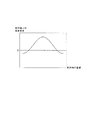
そして、膨出端縁6、7の対向により、例えば、配列軸上における短手方向に垂直な磁束密度は、図2に示すような分布を示す。この磁束密度の分布によれば、膨出端縁6、7が円弧であることにより、配列軸上の磁束密度と配列軸の座標との相関は、例えば、正弦関数にオフセットを加算した正弦曲線に略一致する。そして、このような相関を有する磁束が、磁石2、3とともに長手方向に直線的に変位する。
Then, for example, the magnetic flux density perpendicular to the short direction on the arrangement axis shows a distribution as shown in FIG. According to the distribution of the magnetic flux density, since the bulging
感磁部4、5は、磁石2、3により形成される磁束に感磁してアナログ信号を発生するホール素子(図示せず)と、ホール素子から得られるアナログ信号をデジタル処理する回路(図示せず)とが1パッケージ化されたホールICである。そして、感磁部4、5は、デジタル化された電気的出力を後記する演算回路13に出力する。
The
また、感磁部4、5は、図1(a)に示すように、配列軸上で所定の間隔を有して配列されている。そして、この間隔は、配列軸上の磁束密度と配列軸の座標との相関である正弦曲線の周期2dの1/4の長さd/2である。つまり、感磁部4、5は、d/2だけ離れて配列軸上に配列されている。
Further, as shown in FIG. 1A, the magnetic
なお、感磁部4、5は、互換可能な同一性能、同一特性のホールICである。つまり、感磁部4、5のホール電流Ia、Ibは、各々のホール素子への印加電圧、および各々のホール素子の温度が同一であれば同じ値となり、感磁部4、5のホール係数Ka、Kbも、各々のホール素子の温度が同一であれば同じ値になる。
また、感磁部4、5は、それぞれの感磁面が互いに同一の面方向となるように(例えば、短手方向に垂直となるように)、配されている。
The magnetic
In addition, the
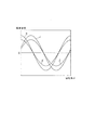
以上により、磁石2、3の長手方向への直線的な変位量(以下、ストローク量Lと呼ぶ)と、感磁部4、5の電気的出力に基づき直接的に求まる磁束密度(つまり、感磁部4、5により直接的に感磁される磁束の磁束密度)との相関は、例えば、図3の特性線α、βに示すように、互いの位相差がd/2の正弦関数にオフセットを加算した正弦曲線に略一致する。
As described above, the magnetic flux density (that is, the sensitivity) obtained directly based on the linear displacement amount in the longitudinal direction of the
すなわち、特性線αは、ストローク量Lを変数とする正弦関数にオフセットを加算した正弦曲線に略一致し、特性線βは、特性線αをd/2だけ平行移動したものになる。ここで、d/2は、特性線αの周期2dの1/4に相当するから、特性線βは、ストローク量Lを変数とする余弦関数にオフセットを加算した余弦曲線に略一致する。なお、特性線α、βの振幅は同一である。 That is, the characteristic line α substantially coincides with a sine curve obtained by adding an offset to a sine function having the stroke amount L as a variable, and the characteristic line β is obtained by translating the characteristic line α by d / 2. Here, since d / 2 corresponds to ¼ of the period 2d of the characteristic line α, the characteristic line β substantially matches a cosine curve obtained by adding an offset to a cosine function having the stroke amount L as a variable. The characteristic lines α and β have the same amplitude.
また、感磁部4、5から出力される電気的出力には、図4に示すDSP(デジタル・シグナル・プロセッサの略)14にて各種の演算処理が施される。DSP14は、D/A変換器15とともに1つの演算回路13を構成し、演算回路13は、感磁部4、5としての2つのホールICとともに1つのセンサアセンブリ16を構成する。
In addition, various arithmetic processes are performed on the electrical outputs output from the
DSP14には、感磁部4、5から得られるそれぞれの電気的出力からオフセット量を減ずる第1オフセット調整手段17、第1オフセット調整手段17から得られる2つの算出値を用いて得られる数値に、逆三角関数演算を施す第1逆三角関数演算手段18、およびゲイン調整手段19の機能が具備されている。
The
第1オフセット調整手段17は、特性線α、βにおける磁束密度の最大値と最小値との中間値に相当する数値をオフセット量として、感磁部4、5の電気的出力に基づき直接的に求まる磁束密度から減じるものである。なお、中間値は、例えば、最大値と最小値との加重平均値として算出される。
The first offset adjusting means 17 directly uses the numerical value corresponding to the intermediate value between the maximum value and the minimum value of the magnetic flux density in the characteristic lines α and β as an offset amount based directly on the electrical output of the
これにより、図3における特性線αは、図5に示すように、ストローク量Lを変数とする正弦関数に略一致する特性線α´になり、図3における特性線βは、ストローク量Lを変数とする余弦関数に略一致する特性線β´になる。すなわち、第1オフセット調整手段17の処理を経た磁束密度、つまりオフセット調整後の磁束密度とストローク量Lとの相関は、ストローク量Lを変数とする正弦関数に近似する特性線α´、およびストローク量Lを変数とする余弦関数に近似する特性線β´になる。 As a result, the characteristic line α in FIG. 3 becomes a characteristic line α ′ that substantially matches the sine function with the stroke amount L as a variable, as shown in FIG. 5, and the characteristic line β in FIG. The characteristic line β ′ substantially matches the variable cosine function. That is, the correlation between the magnetic flux density that has been processed by the first offset adjusting means 17, that is, the magnetic flux density after offset adjustment, and the stroke amount L is a characteristic line α ′ that approximates a sine function with the stroke amount L as a variable, and the stroke The characteristic line β ′ approximates to a cosine function with the quantity L as a variable.
したがって、オフセット調整後の磁束密度に相当する出力値、つまり、2つのホールIC(感磁部4、5)から出力されるホール電圧をオフセット調整した出力電圧Va、Vbは、各々の振幅Ea、Ebを用いると下記の数式1、2を近似式として表される。
〔数式1〕
Va=Ea・sinL
〔数式2〕
Vb=Eb・cosL
Therefore, the output value Va, Vb obtained by offset adjustment of the output value corresponding to the magnetic flux density after the offset adjustment, that is, the Hall voltage output from the two Hall ICs (
[Formula 1]
Va = Ea · sinL
[Formula 2]
Vb = Eb · cosL
また、振幅Ea、Ebは、図2に示す磁束密度の分布の振幅をBで表記すると、下記の数式3、4で表される。
〔数式3〕
Ea=Ka・Ia・B
〔数式4〕
Eb=Kb・Ib・B
Further, the amplitudes Ea and Eb are expressed by the following
[Formula 3]
Ea = Ka ・ Ia ・ B
[Formula 4]
Eb = Kb / Ib / B
ここで、感磁部4、5は、互換可能な同一性能、同一特性のホールICであり、同じ温度の雰囲気で使用されているので、ホール電流Ia、Ibは互いに等しく、ホール係数Ka、Kbも互いに等しい。また、感磁部4、5が感磁する磁束は、両方とも磁石2、3により形成される同じ磁束であるからBの数値も互いに等しい。このため、振幅Ea、Ebは、互いに等しくなるので、数式5に示すように、Va/Vbは、ストローク量Lを変数とする正接に略一致する。
〔数式5〕
Va/Vb=tanL
Here, since the magnetic
[Formula 5]
Va / Vb = tanL
よって、下記の数式6に示すように、Va/Vbに逆三角関数演算を施すことによりストローク量Lを求めることができる。
〔数式6〕
L=arctan(Va/Vb)
Therefore, as shown in
[Formula 6]
L = arctan (Va / Vb)
第1逆三角関数演算手段18は、第1オフセット調整手段17から得られる2つの算出値を互いに除して得られる数値に逆三角関数演算を施すことで、数式5、6に相当する演算処理を行うものである。そして、第1逆三角関数演算手段18は、逆三角関数演算により得られた数値に、下記の数式7に相当する演算処理を施し、この演算処理により得られた数値をストローク量Lに関する出力値V(L)とする。
〔数式7〕
V(L)=arctan(Va/Vb)・d/π
The first inverse trigonometric function calculation means 18 performs an inverse trigonometric function calculation on the numerical value obtained by dividing the two calculated values obtained from the first offset adjustment means 17, so that the calculation processes corresponding to the
[Formula 7]
V (L) = arctan (Va / Vb) · d / π
これにより、ストローク量Lに対する出力値V(L)は、図6に示すように、ストローク量Lの実使用範囲において理想的なリニア特性を示す。そして、算出された出力値V(L)に相当するデジタル信号が、D/A変換器15によりアナログ処理されてECUに出力される(図4参照)。
なお、ゲイン調整手段19は、振幅Ea、Ebが電気的な差異により互いに等しくならないときに、振幅Ea、Ebが互いに等しくなるように電気的な調整を行うものである。
Thereby, the output value V (L) with respect to the stroke amount L exhibits an ideal linear characteristic in the actual use range of the stroke amount L as shown in FIG. A digital signal corresponding to the calculated output value V (L) is analog processed by the D /
The gain adjusting means 19 performs electrical adjustment so that the amplitudes Ea and Eb are equal to each other when the amplitudes Ea and Eb are not equal to each other due to an electrical difference.
〔実施例1の効果〕
実施例1のストロークセンサ1は、互いに、自身の長手方向が平行となるように、かつ長手方向と垂直な短手方向に対向するように配され、被検出体の直線的な変位に応じて長手方向に直線的に変位する2つの磁石2、3と、2つの磁石2、3により短手方向に挟まれるように、かつ、互いに長手方向に離されて、長手方向に平行するように配される2つの感磁部4、5とを備える。
[Effect of Example 1]
The
磁石2、3は、各々、円弧状の膨出端縁6、7を有しており、膨出端縁6、7は、互いに配列軸を挟んで鏡映対象をなすように対向している。また、磁石2、3は、膨出端縁6の側の極性と膨出端縁7の側の極性とが逆になるように着磁されて配されている。そして、磁石2、3は、このような膨出端縁6、7の位置関係を保ちながら長手方向に直線的に変位する。
The
この結果、感磁部4、5が並ぶ配列軸上の磁束密度の分布は、例えば、周期2dの正弦関数にオフセットを加算した正弦曲線に略一致し(図2参照)、このような分布を有する磁束が、磁石2、3とともに長手方向に変位する。また、感磁部4、5は、このように変位する磁束に感磁することで、自身が発生する電気的出力を可変する。なお、感磁部4、5は、d/2だけ離れて配列軸上に配列されている。
As a result, the distribution of the magnetic flux density on the arrangement axis in which the magnetic
これにより、ストローク量Lと感磁部4の電気的出力に基づき算出される磁束密度との相関である特性線α、および、ストローク量Lと感磁部5の電気的出力に基づき算出される磁束密度との相関である特性線βは、両方とも正弦曲線に略一致する。また、特性線α、βは、同一周期かつ位相差が周期の1/4になる(図3参照)。
このため、特性線αをオフセット調整した特性線α´を、ストローク量Lを変数とする正弦関数とみなせば、特性線βをオフセット調整した特性線β´を、ストローク量Lを変数とする余弦関数とみなすことができる(図5参照)。
Thus, the characteristic line α, which is a correlation between the stroke amount L and the magnetic flux density calculated based on the electrical output of the
Therefore, if the characteristic line α ′ obtained by adjusting the offset of the characteristic line α is regarded as a sine function using the stroke amount L as a variable, the characteristic line β ′ obtained by adjusting the offset of the characteristic line β is used as a cosine using the stroke amount L as a variable. It can be regarded as a function (see FIG. 5).
したがって、感磁部4から出力されるホール電圧をオフセット調整した出力電圧Vaを、感磁部5から出力されるホール電圧をオフセット調整した出力電圧Vbで除することにより、ストローク量Lを変数とする正接に相当する数値を得ることができる。また、磁石2、3により形成される磁束の温度特性や、感磁部4、5から得られる電気的出力の温度特性を、除算によりキャンセルすることができる(数式5参照)。
Therefore, by dividing the output voltage Va obtained by offset adjustment of the Hall voltage output from the
この結果、得られた正接を逆三角関数処理することで、ストローク量Lと逆三角関数処理により得られた数値との相関を、磁束の温度特性や電気的出力の温度特性の影響を受けない理想的なリニア特性とすることができる(数式6、7参照)。
以上により、可動子としての磁石2、3によって形成される磁束や、固定子としての感磁部4、5から得られる電気的出力が温度に応じて変動しても、ストローク量Lに関して精度の高い出力値V(L)を得ることができる。
As a result, the obtained tangent is subjected to the inverse trigonometric function process, so that the correlation between the stroke amount L and the numerical value obtained by the inverse trigonometric function process is not affected by the temperature characteristic of the magnetic flux or the temperature characteristic of the electrical output. Ideal linear characteristics can be obtained (see
As described above, even when the magnetic flux formed by the
また、配列軸を中心軸として磁石2、3が回転しても、感磁部4、5がそれぞれ感磁する磁束密度は同じ比率で変動する。このため、磁石2、3の回転に伴うストローク量Lの検出誤差を抑制することができる。
Further, even if the
また、感磁部4、5間の距離が特性線α、βの周期2dの1/4であるから、上記のように、特性線α´を、ストローク量Lを変数とする正弦関数とみなせば、特性線β´を、ストローク量Lを変数とする余弦関数とみなすことができる。
このため、感磁部4、5間の距離が周期2dの1/4でない場合に比べて、ストローク量Lを簡便に算出することができるので、演算負荷を下げることができる。
Further, since the distance between the
For this reason, compared with the case where the distance between the magnetic
また、膨出端縁6、7は、配列軸のいずれの座標で長手方向に垂直に切断されても、切断線8、9は、第3の方向に平行かつ互いに同一長さの線分をなす(図1(b)参照)。
これにより、配列軸上の磁束密度の分布を、より確実に正弦曲線に近似させることができる。
Even if the bulging
Thereby, the distribution of the magnetic flux density on the arrangement axis can be more reliably approximated to a sine curve.
ここで、実施例1の円弧状膨出形の磁石2、3を採用した場合に、配列軸上の磁束密度の分布(配列軸上の磁束密度と配列軸の座標との相関)が正弦曲線に近づくこと、および、ストローク量Lに対する誤差が小さくなることを、図7に示す単純棒形の磁石との比較により説明する(以下、比較対象となる単純棒形の磁石を比較磁石と呼ぶ)。なお、図7(a)は、実施例1の円弧状膨出形の磁石2、3間に形成される磁束を、磁力線を用いて示すものであり、図7(b)は、2つの比較磁石間に形成される磁束を、磁力線を用いて示すものである。
Here, when the arc-shaped bulge-shaped
磁石2、3のような膨出形の場合、磁石2、3の対向範囲の配列軸上において、磁束密度に相当する磁力線間隔の疎密は、図7(a)に示すように、膨出端縁6、7間の短手方向の距離が最も小さい中央位置で最も密になり、膨出端縁6、7間の短手方向の距離が最も大きい図示左右両端の端位置で最も疎になる。また、配列軸上の磁力線間隔の疎密は、中央位置から両方の端位置に向かって徐々に疎になる。そして、膨出端縁6、7を円弧状に設けることで、配列軸上の磁力線間隔の疎密と配列軸の座標との相関を正弦曲線に略一致させることができる(図8(a)の円弧状膨出形の磁石の相関を参照)。
In the case of the bulging type such as the
これに対し、比較磁石の場合、2つの比較磁石の対向範囲の配列軸上において、磁力線間隔の疎密は、図7(b)に示すように、中央位置を含む広範囲でほぼ一定になり、図示左右両端の端位置の近傍で中央位置よりも疎になる。このため、配列軸上の磁力線間隔の疎密は、中央位置から両方の端位置に向かって一定に保たれ、所定の位置を超えた後、急激に疎になる(図8(a)の比較磁石の相関を参照)。 On the other hand, in the case of the comparative magnet, on the arrangement axis in the range where the two comparative magnets face each other, the density of the lines of magnetic force is almost constant over a wide range including the central position as shown in FIG. It is sparser than the center position in the vicinity of the left and right end positions. For this reason, the density of the magnetic field lines on the arrangement axis is kept constant from the center position toward both end positions, and after reaching a predetermined position, the density becomes abruptly sparse (the comparative magnet shown in FIG. 8A). See correlation).
この結果、比較磁石を可動子に採用した場合、ストローク量Lに対する出力値V(L)の相関は、ストローク量Lの実使用範囲において理想的なリニア特性とならず、ストローク量Lに対する誤差は、円弧状膨出形の磁石2、3よりも大きくなる(図8(b)参照)。
As a result, when the comparative magnet is used for the mover, the correlation between the output value V (L) and the stroke amount L is not an ideal linear characteristic in the actual usage range of the stroke amount L, and the error with respect to the stroke amount L is It becomes larger than the arc-shaped
〔実施例2〕
実施例2のストロークセンサ1によれば、感磁部4、5は、互換可能な同一性能、同一特性のホール素子であり、図9に示すように、第1オフセット調整手段17、第1逆三角関数演算手段18およびゲイン調整手段19の機能を具備するDSP14とともに1つのチップ20で構成されている。
[Example 2]
According to the
なお、チップ20は、感磁部4、5としてのホール素子からの出力信号を増幅するオペアンプ21、22、増幅された出力信号をデジタル処理するA/D変換器23、およびD/A変換器15の機能も含むように設けられている。
これにより、ストロークセンサ1の体格を小型化することができるとともに、感磁部4、5の性能、特性を、より同一にすることができる。
The
Thereby, the physique of the
〔実施例3〕
実施例3のストロークセンサ1によれば、図10に示すように、磁石2、3は、それぞれ、膨出端縁6、7と着磁方向に反対側の周縁26、27が磁性体28により覆われている。
これにより、外乱磁場に対するロバスト性を高めることができる。
Example 3
According to the
Thereby, the robustness with respect to a disturbance magnetic field can be improved.
〔実施例4の構成〕
実施例4のストロークセンサ1の構成を、図11〜図22を用いて説明する。
なお、実施例4のストロークセンサ1は、ストローク量Lとともに回転角θを検出することができるものであり、例えば、トロイダルCVTにおいて、パワーローラを傾転自在に支持するトラニオンの傾転軸方向に関する位置および傾転角度を、両方とも把握するために好適に利用できる。
[Configuration of Example 4]
The structure of the
The
実施例4のストロークセンサ1によれば、感磁部4、5とは別の感磁部30が、感磁部4と配列軸上で略同一の位置に配され、感磁部30とはさらに別の感磁部31が、感磁部5と配列軸上で略同一の位置に配されている。
According to the
感磁部4、30は、それぞれの感磁面が90°よりも小さい角度θcをなすように配され、感磁部5、31も、それぞれの感磁面が角度θcをなすように配されている。また、感磁部4、5は、それぞれの感磁面が同一の面方向をなすように配され、感磁部30、31も、それぞれの感磁面が同一の面方向をなすように配されている。さらに、感磁部4、30と感磁部5、31とは、d/2よりも短い距離eだけ離れて配列軸上に配されている。また、感磁部4、5、30、31は、互換可能な同一性能、同一特性のホール素子である。
The magnetic
そして、被検出体は直線的に変位するとともに回転し、磁石2、3は、被検出体の直線的な変位に応じて感磁部4、5、30、31に対し長手方向に相対的に変位するとともに、被検出体の回転に応じて感磁部4、5、30、31に対し相対的に回転する。
The detected object is linearly displaced and rotated, and the
以上により、回転角θが0°の場合、磁石2、3の長手方向へのストローク量Lと、感磁部4、5の電気的出力に基づき直接的に求まる磁束密度との相関は、例えば、図12の特性線γ、δに示すように、互いの位相差がeの正弦関数にオフセットを加算した正弦曲線に略一致する。また、ストローク量Lと、感磁部30、31の電気的出力に基づき直接的に求まる磁束密度との相関は、例えば、図12の特性線ε、ζに示すように、互いの位相差がeの正弦関数にオフセットを加算した正弦曲線に略一致する。
As described above, when the rotation angle θ is 0 °, the correlation between the stroke amount L in the longitudinal direction of the
すなわち、特性線γ、δおよび特性線ε、ζは、ストローク量Lを変数とする正弦関数にオフセットを加算した正弦曲線に略一致し、特性線δ、ζは、特性線γ、εを、それぞれeだけ平行移動したものになる。また、特性線γ、δの振幅は互いに等しく、特性線ε、ζの振幅は互いに等しい。そして、特性線γ、δの振幅と特性線ε、ζの振幅との大小関係は、後記するように回転角θに応じて変化する。 That is, the characteristic lines γ and δ and the characteristic lines ε and ζ substantially coincide with a sine curve obtained by adding an offset to a sine function with the stroke amount L as a variable, and the characteristic lines δ and ζ are characteristic lines γ and ε, Each is translated by e. Further, the amplitudes of the characteristic lines γ and δ are equal to each other, and the amplitudes of the characteristic lines ε and ζ are equal to each other. The magnitude relationship between the amplitudes of the characteristic lines γ and δ and the amplitudes of the characteristic lines ε and ζ varies according to the rotation angle θ as will be described later.
また、ストローク量Lが0の場合、磁石2、3の回転角θと感磁部4、30の電気的出力に基づき直接的に求まる磁束密度との相関は、例えば、図13の特性線η、ιに示すように、互いの位相差がθcの正弦曲線に略一致する。また、回転角θと、感磁部5、31の電気的出力に基づき直接的に求まる磁束密度との相関は、例えば、図13の特性線κ、λに示すように、互いの位相差がθcの正弦曲線に略一致する。
When the stroke amount L is 0, the correlation between the rotation angle θ of the
すなわち、特性線η、ιおよび特性線κ、λは、回転角θを変数とする正弦曲線に略一致し、特性線ι、λは、特性線η、κを、それぞれθcだけ平行移動したものになる。また、特性線η、ιの振幅は互いに等しく、特性線κ、λの振幅は互いに等しい。そして、特性線η、ιの振幅と特性線κ、λの振幅との大小関係は、後記するようにストローク量Lに応じて変化する。 That is, the characteristic lines η and ι and the characteristic lines κ and λ substantially coincide with a sine curve having the rotation angle θ as a variable, and the characteristic lines ι and λ are obtained by translating the characteristic lines η and κ by θc, respectively. become. The amplitudes of the characteristic lines η and ι are equal to each other, and the amplitudes of the characteristic lines κ and λ are equal to each other. The magnitude relationship between the amplitudes of the characteristic lines η and ι and the amplitudes of the characteristic lines κ and λ changes according to the stroke amount L as described later.
また、感磁部4、5、30、31は、それぞれホール素子であり、図14に示すように、感磁部4、5は、1つのチップ20aに含まれており、感磁部30、31は、チップ20aとは別の1つのチップ20bに含まれている。そして、センサアセンブリ16は、チップ20a、20bとともに演算回路13を有し、演算回路13は、実施例1と同様に、DSP14およびD/A変換器15等を有する。
The magnetic
ここで、実施例4のDSP14は、第1オフセット調整手段17、第1逆三角関数演算手段18とともに、後記する第2オフセット調整手段33、および第2〜第4逆三角関数演算手段34〜36の機能を有する。
Here, the
また、チップ20aは、オペアンプ21、22の機能とともに、オペアンプ21、22で増幅された出力信号をデジタル処理するA/D変換器23aの機能を含んでおり、デジタル処理された出力信号は演算回路13に出力される。さらに、チップ20bは、感磁部30、31からの出力信号をそれぞれ増幅するオペアンプ38、39の機能とともに、オペアンプ38、39で増幅された出力信号をデジタル処理するA/D変換器23bの機能を含んでおり、デジタル処理された出力信号は演算回路13に出力される。
The
第2オフセット調整手段33は、感磁部30、31から得られるそれぞれの電気的出力からオフセット量を減じるものであり、例えば、特性線ε、ζにおける磁束密度の最大値と最小値との中間値に相当する数値をオフセット量として、感磁部30、31の電気的出力に基づき直接的に求まる磁束密度から減じるものである。なお、中間値は、例えば、最大値と最小値との加重平均値として算出される。
The second offset adjusting unit 33 subtracts the offset amount from the respective electrical outputs obtained from the
なお、第1オフセット調整手段17は、実施例1と同様に、感磁部4、5から得られるそれぞれの電気的出力からオフセット量を減じる。すなわち、実施例4の第1オフセット調整手段17は、特性線γ、δにおける磁束密度の最大値と最小値との中間値に相当する数値をオフセット量として、感磁部4、5の電気的出力に基づき直接的に求まる磁束密度から減じる
The first offset adjusting means 17 subtracts the offset amount from the respective electrical outputs obtained from the magnetic
そして、図12における特性線γ、δは、第1オフセット調整手段17の処理を経ることで、図15に示すように、それぞれ、ストローク量Lを変数とする正弦関数に略一致する特性線γ´、δ´になる。また、特性線ε、ζは、第2オフセット調整手段33の処理を経ることで、それぞれ、ストローク量Lを変数とする正弦関数に略一致する特性線ε´、ζ´になる。 Then, the characteristic lines γ and δ in FIG. 12 are processed by the first offset adjusting means 17 so that the characteristic lines γ substantially coincide with the sine function having the stroke amount L as a variable as shown in FIG. 'And δ'. Further, the characteristic lines ε and ζ become characteristic lines ε ′ and ζ ′ that substantially match the sine function having the stroke amount L as a variable, respectively, through the processing of the second offset adjusting means 33.
ここで、特性線γ´、δ´は、互いの位相差がeとなる2つの正弦関数であり、特性線δ´は、特性線γ´をeだけ平行移動したものになる。また、特性線γ´、δ´の振幅は互いに等しい。
同様に、特性線ε´、ζ´は、互いの位相差がeとなる2つの正弦関数であり、特性線ζ´は、特性線ε´をeだけ平行移動したものになる。また、特性線ε´、ζ´の振幅は互いに等しい。
Here, the characteristic lines γ ′ and δ ′ are two sine functions whose phase difference is e, and the characteristic line δ ′ is obtained by translating the characteristic line γ ′ by e. Further, the amplitudes of the characteristic lines γ ′ and δ ′ are equal to each other.
Similarly, the characteristic lines ε ′ and ζ ′ are two sine functions whose phase difference is e, and the characteristic line ζ ′ is obtained by translating the characteristic line ε ′ by e. The amplitudes of the characteristic lines ε ′ and ζ ′ are equal to each other.
したがって、感磁部4、5から出力されるホール電圧を増幅してオフセット調整した出力電圧Vc、Vdは、各々の振幅Ec、Edを用いるとともにストローク量Lを変数として用いると、下記の数式8、9を近似式として表される。
〔数式8〕
Vc=Ec・sinL
〔数式9〕
Vd=Ed・sin(L−e)
Therefore, the output voltages Vc and Vd obtained by amplifying the Hall voltage output from the
[Formula 8]
Vc = Ec · sinL
[Formula 9]
Vd = Ed · sin (L−e)
また、感磁部30、31から出力されるホール電圧を増幅してオフセット調整した出力電圧Ve、Vfは、各々の振幅Ee、Efを用いるとともにストローク量Lを変数として用いると、下記の数式10、11を近似式として表される。
〔数式10〕
Ve=Ee・sinL
〔数式11〕
Vf=Ef・sin(L−e)
Further, the output voltages Ve and Vf obtained by amplifying the Hall voltage output from the
[Formula 10]
Ve = Ee · sinL
[Formula 11]
Vf = Ef · sin (L−e)
ここで、実施例1の振幅Ea、Ebと同様に、振幅Ec、Edは互いに等しく、振幅Ee、Efも互いに等しい。このため、例えば、出力電圧Vc、Vdの差(Vc−Vd)および和(Vc+Vd)を求め、差(Vc−Vd)を和(Vc+Vd)で除することにより、磁束の温度特性や電気的出力の温度特性をキャンセルすることができる。また、出力電圧Ve、Vfの差(Ve−Vf)および和(Ve+Vf)を求め、差(Ve−Vf)を和(Ve+Vf)で除することによっても、磁束の温度特性や電気的出力の温度特性をキャンセルすることができる。 Here, similarly to the amplitudes Ea and Eb of the first embodiment, the amplitudes Ec and Ed are equal to each other, and the amplitudes Ee and Ef are also equal to each other. Therefore, for example, by calculating the difference (Vc−Vd) and the sum (Vc + Vd) between the output voltages Vc and Vd and dividing the difference (Vc−Vd) by the sum (Vc + Vd), the temperature characteristics and electric output of the magnetic flux The temperature characteristic of can be canceled. Also, the temperature characteristics of the magnetic flux and the temperature of the electrical output can be obtained by calculating the difference (Ve−Vf) and the sum (Ve + Vf) of the output voltages Ve and Vf and dividing the difference (Ve−Vf) by the sum (Ve + Vf). The characteristic can be canceled.
さらに、これらの除算により得た数値から、ストローク量Lを変数とする正接に相当する数値を得ることができ、得られた正接を逆三角関数処理することで、ストローク量Lに関して下記の数式12、13を得ることができる。
〔数式12〕
L=arctan〔cot{e/2・π/d・(Vc−Vd)/(Vc+Vd)}〕
〔数式13〕
L=arctan〔cot{e/2・π/d・(Ve−Vf)/(Ve+Vf)}〕
Furthermore, a numerical value corresponding to a tangent with the stroke amount L as a variable can be obtained from the numerical values obtained by these divisions, and the obtained tangent is subjected to inverse trigonometric function processing, whereby the following equation 12 is obtained with respect to the stroke amount L. , 13 can be obtained.
[Formula 12]
L = arctan [cot {e / 2 · π / d · (Vc−Vd) / (Vc + Vd)}]
[Formula 13]
L = arctan [cot {e / 2 · π / d · (Ve−Vf) / (Ve + Vf)}]
第1逆三角関数演算手段18は、第1オフセット調整手段17から得られる2つの算出値(出力電圧Vc、Vd)を用いて得られる数値に逆三角関数演算を施すことで、数式12に相当する演算処理を行うものである。そして、第1逆三角関数演算手段18は、逆三角関数演算により得られた数値に、下記の数式14に相当する演算処理を施し、この演算処理により得られた数値をストローク量Lに関する出力値V(L)とする。
〔数式14〕
V(L)=arctan〔cot{e/2・π/d・(Vc−Vd)/(Vc+Vd)}〕・d/π
The first inverse trigonometric function computing means 18 corresponds to the mathematical expression 12 by performing inverse trigonometric function computation on the numerical value obtained using the two calculated values (output voltages Vc, Vd) obtained from the first offset adjusting means 17. The arithmetic processing to perform is performed. Then, the first inverse trigonometric function calculation means 18 performs a calculation process corresponding to the following
[Formula 14]
V (L) = arctan [cot {e / 2 · π / d · (Vc−Vd) / (Vc + Vd)}] · d / π
また、第3逆三角関数演算手段35は、第2オフセット調整手段33から得られる2つの算出値(出力電圧Ve、Vf)を用いて得られる数値に逆三角関数演算を施すことで、数式13に相当する演算処理を行うものである。そして、第3逆三角関数演算手段35は、逆三角関数演算により得られた数値に、下記の数式15に相当する演算処理を施し、この演算処理により得られた数値をストローク量Lに関する出力値V(L)とする。
〔数式15〕
V(L)=arctan〔cot{e/2・π/d・(Ve−Vf)/(Ve+Vf)}〕・d/π
Further, the third inverse trigonometric function calculation means 35 performs the inverse trigonometric function calculation on the numerical value obtained by using the two calculated values (output voltages Ve and Vf) obtained from the second offset adjustment means 33, thereby obtaining
[Formula 15]
V (L) = arctan [cot {e / 2 · π / d · (Ve−Vf) / (Ve + Vf)}] · d / π
以上により、感磁部4、5から出力されるホール電圧(つまり、特性線γ、δにより示される磁束密度に相当する)を利用することにより、ストローク量Lに対する出力値V(L)を、図6と同様に、ストローク量Lの実使用範囲において理想的なリニア特性にすることができる。同様に、感磁部30、31から出力されるホール電圧(つまり、特性線ε、ζにより示される磁束密度に相当する)を利用することによっても、ストローク量Lに対する出力値V(L)を、図6と同様に、ストローク量Lの実使用範囲において理想的なリニア特性にすることができる。
As described above, by using the Hall voltage output from the
次に、感磁部4、30から出力されるホール電圧を増幅した後、第1、第2オフセット調整手段17、33のそれぞれにより処理することなく得られる出力電圧Vg、Vhを考えると、出力電圧Vg、Vhは、各々の振幅Eg、Ehを用いるとともに回転角θを変数として用いると、下記の数式16、17を近似式として表される。
〔数式16〕
Vg=Eg・sinθ
〔数式17〕
Vh=Eh・sin(θ−θc)
Next, when the output voltages Vg and Vh obtained by amplifying the Hall voltage output from the
[Formula 16]
Vg = Eg · sin θ
[Formula 17]
Vh = Eh · sin (θ−θc)
また、感磁部5、31から出力されるホール電圧を増幅した後、第1、第2オフセット調整手段17、33のそれぞれにより処理することなく得られる出力電圧Vi、Vjを考えると、出力電圧Vi、Vjは、各々の振幅Ei、Ejを用いるとともに回転角θを変数として用いると、下記の数式18、19を近似式として表される。
〔数式18〕
Vi=Ei・sinθ
〔数式19〕
Vj=Ej・sin(θ−θc)
Further, when the output voltages Vi and Vj obtained by amplifying the Hall voltage output from the
[Formula 18]
Vi = Ei · sin θ
[Formula 19]
Vj = Ej · sin (θ−θc)
ここで、実施例1の振幅Ea、Ebと同様に、振幅Eg、Ehは互いに等しく、振幅Ei、Ejも互いに等しい。このため、例えば、出力電圧Vg、Vhの差(Vg−Vh)および和(Vg+Vh)を求め、差(Vg−Vh)を和(Vg+Vh)で除することにより、磁束の温度特性や電気的出力の温度特性をキャンセルすることができる。また、出力電圧Vi、Vjの差(Vi−Vj)および和(Vi+Vj)を求め、差(Vi−Vj)を和(Vi+Vj)で除することによっても、磁束の温度特性や電気的出力の温度特性をキャンセルすることができる。 Here, similarly to the amplitudes Ea and Eb of the first embodiment, the amplitudes Eg and Eh are equal to each other, and the amplitudes Ei and Ej are also equal to each other. Therefore, for example, by calculating the difference (Vg−Vh) and the sum (Vg + Vh) between the output voltages Vg and Vh and dividing the difference (Vg−Vh) by the sum (Vg + Vh), the temperature characteristics of the magnetic flux and the electrical output The temperature characteristic of can be canceled. Further, by calculating the difference (Vi−Vj) and the sum (Vi + Vj) between the output voltages Vi and Vj and dividing the difference (Vi−Vj) by the sum (Vi + Vj), the temperature characteristics of the magnetic flux and the temperature of the electrical output are also obtained. The characteristic can be canceled.
さらに、これらの除算により得た数値から、回転角θを変数とする正接に相当する数値を得ることができ、得られた正接を逆三角関数処理することで、回転角θに関して下記の数式20、21を得ることができる。
〔数式20〕
θ=arctan〔cot{θc/2・π/180°・(Vg−Vh)/(Vg+Vh)}〕
〔数式21〕
θ=arctan〔cot{θc/2・π/180°・(Vi−Vj)/(Vi+Vj)}〕
Furthermore, a numerical value corresponding to a tangent having the rotation angle θ as a variable can be obtained from the numerical values obtained by these divisions, and the obtained tangent is subjected to inverse trigonometric function processing, whereby the following
[Formula 20]
θ = arctan [cot {θc / 2 · π / 180 ° · (Vg−Vh) / (Vg + Vh)}]
[Formula 21]
θ = arctan [cot {θc / 2 · π / 180 ° · (Vi−Vj) / (Vi + Vj)}]
第2逆三角関数演算手段34は、感磁部4、30のホール電圧を用いて得られる数値(出力電圧Vg、Vh)に逆三角関数演算を施すことで、数式20に相当する演算処理を行うものである。そして、第2逆三角関数演算手段34は、逆三角関数演算により得られた数値に、下記の数式22に相当する演算処理を施し、この演算処理により得られた数値を回転角θに関する出力値V(θ)とする。
〔数式22〕
V(θ)=arctan〔cot{θc/2・π/180°・(Vg−Vh)/(Vg+Vh)}〕・180°/π
The second inverse trigonometric function computing means 34 performs an inverse trigonometric function computation on the numerical values (output voltages Vg, Vh) obtained using the Hall voltages of the
[Formula 22]
V (θ) = arctan [cot {θc / 2 · π / 180 ° · (Vg−Vh) / (Vg + Vh)}] · 180 ° / π
第4逆三角関数演算手段36は、感磁部5、31のホール電圧を用いて得られる数値(出力電圧Vi、Vj)に逆三角関数演算を施すことで、数式21に相当する演算処理を行うものである。そして、第4逆三角関数演算手段36は、逆三角関数演算により得られた数値に、下記の数式23に相当する演算処理を施し、この演算処理により得られた数値を回転角θに関する出力値V(θ)とする。
〔数式23〕
V(θ)=arctan〔cot{θc/2・π/180°・(Vi−Vj)/(Vi+Vj)}〕・180°/π
The fourth inverse trigonometric function computing means 36 performs an inverse trigonometric function computation on numerical values (output voltages Vi, Vj) obtained by using the Hall voltages of the
[Formula 23]
V (θ) = arctan [cot {θc / 2 · π / 180 ° · (Vi−Vj) / (Vi + Vj)}] · 180 ° / π
以上により、感磁部4、30から出力されるホール電圧(つまり、特性線η、ιにより示される磁束密度に相当する)を利用することにより、回転角θに対する出力値V(θ)を、図16に示すように、回転角θが0°〜360°の範囲において理想的なリニア特性にすることができる。同様に、感磁部5、31から出力されるホール電圧(つまり、特性線κ、λにより示される磁束密度に相当する)を利用することによっても、回転角θに対する出力値V(θ)を、図16に示すように、回転角θが0°〜360°の範囲において理想的なリニア特性にすることができる。
As described above, by using the Hall voltage output from the
そして、実施例4のDSP14は、ストローク量Lの検出に関して、感磁部4、5から得られる出力電圧Vc、Vdの組合せ(以下、第1組合せと呼ぶ)、または、感磁部30、31から得られる出力電圧Ve、Vfの組合せ(以下、第3組合せと呼ぶ)のいずれか一方を選択して出力値V(L)を算出する。すなわち、DSP14は、第1オフセット調整手段17および第1逆三角関数演算手段18、または第2オフセット調整手段33および第3逆三角関数演算手段35のいずれか一方を選択して出力値V(L)を算出する。
The
また、DSP14は、回転角θの検出に関して、感磁部4、30から得られる出力電圧Vg、Vhの組合せ(以下、第2組合せと呼ぶ)、または、感磁部5、31から得られる出力電圧Vi、Vjの組合せ(以下、第4組合せと呼ぶ)のいずれか一方を選択して出力値V(θ)を算出する。すなわち、DSP14は、第2逆三角関数演算手段34または第4逆三角関数演算手段36のいずれか一方を選択して出力値V(θ)を算出する。
Further, the
ここで、磁石2、3により形成される磁束は、配列軸上の磁束密度と配列軸の座標との相関が正弦曲線に略一致するような特異なものであることから、感磁部4、5、30、31がそれぞれ感磁する磁束密度は、ストローク量Lや回転角θに応じて異なる。
そこで、DSP14は、ストローク量Lを検出する際に、出力値V(L)に対するS/N比を高めるため、回転角θを目安として、第1、第3組合せの内、感磁する磁束密度が大きい方の組合せを選択して出力値V(L)を算出する。
Here, since the magnetic flux formed by the
Therefore, when detecting the stroke amount L, the
例えば、図13に示すように、特性線ηの磁束密度(感磁部4の電気的出力に基づき直接的に求まる磁束密度)と、特性線ιの磁束密度(感磁部30の電気的出力に基づき直接的に求まる磁束密度)とに関して絶対値が互いに等しくなるときの回転角θの数値をθ1〜θ4とする。
この場合、回転角θがθ1よりも小さい範囲では、特性線ηの方が特性線ιよりも磁束密度の絶対値が大きいので、感磁部4が感磁する磁束密度の方が、感磁部30が感磁する磁束密度よりも大きい。
For example, as shown in FIG. 13, the magnetic flux density of the characteristic line η (magnetic flux density obtained directly based on the electrical output of the magnetic sensing unit 4) and the magnetic flux density of the characteristic line ι (electrical output of the magnetic sensing unit 30). The numerical values of the rotation angle θ when the absolute values are equal to each other with respect to the magnetic flux density (directly obtained based on the above) are θ1 to θ4.
In this case, in the range where the rotation angle θ is smaller than θ1, the characteristic line η has a larger absolute value of the magnetic flux density than the characteristic line ι. It is larger than the magnetic flux density that the
このため、例えば図17に示すように、特性線γ(感磁部4の電気的出力に基づき直接的に求まる磁束密度とストローク量Lとの相関)における振幅は、特性線ε(感磁部30の電気的出力に基づき直接的に求まる磁束密度とストローク量Lとの相関)における振幅よりも大きくなる。そこで、DSP14は、回転角θがθ1よりも小さい場合、ストローク量Lの検出に関して第1組合せを選択し、第1オフセット調整手段17および第1逆三角関数演算手段18により出力値V(L)を算出する。
Therefore, for example, as shown in FIG. 17, the amplitude in the characteristic line γ (correlation between the magnetic flux density directly determined based on the electrical output of the
また、回転角θがθ1よりも大きくθ2よりも小さい範囲では、特性線ιの方が特性線ηよりも磁束密度の絶対値が大きいので、感磁部30が感磁する磁束密度の方が、感磁部4が感磁する磁束密度よりも大きい。このため、例えば図18に示すように、特性線εにおける振幅は、特性線γにおける振幅よりも大きくなる。そこで、DSP14は、回転角θがθ1よりも大きくθ2よりも小さい場合、ストローク量Lの検出に関して第3組合せを選択し、第2オフセット調整手段33および第3逆三角関数演算手段35により出力値V(L)を算出する。
In the range where the rotation angle θ is larger than θ1 and smaller than θ2, the characteristic line ι has a larger magnetic flux density absolute value than the characteristic line η. It is larger than the magnetic flux density that the
また、回転角θがθ2よりも大きくθ3よりも小さい範囲では、特性線ηの方が特性線ιよりも磁束密度の絶対値が大きいので、感磁部4が感磁する磁束密度の方が、感磁部30が感磁する磁束密度よりも大きい。このため、例えば図19に示すように、特性線γにおける振幅は、特性線εにおける振幅よりも大きくなる。そこで、DSP14は、回転角θがθ2よりも大きくθ3よりも小さい場合、ストローク量Lの検出に関して第1組合せを選択し、第1オフセット調整手段17および第1逆三角関数演算手段18により出力値V(L)を算出する。
In the range where the rotation angle θ is larger than θ2 and smaller than θ3, the characteristic line η has a larger absolute value of the magnetic flux density than the characteristic line ι. It is larger than the magnetic flux density that the
また、回転角θがθ3よりも大きくθ4よりも小さい範囲では、特性線ιの方が特性線ηよりも磁束密度の絶対値が大きいので、感磁部30が感磁する磁束密度の方が、感磁部4が感磁する磁束密度よりも大きい。このため、特性線εにおける振幅は、特性線γにおける振幅よりも大きくなる。そこで、DSP14は、回転角θがθ3よりも大きくθ4よりも小さい場合、ストローク量Lの検出に関して第3組合せを選択し、第2オフセット調整手段33および第3逆三角関数演算手段35により出力値V(L)を算出する。
In the range where the rotation angle θ is larger than θ3 and smaller than θ4, the characteristic line ι has a larger absolute value of the magnetic flux density than the characteristic line η. It is larger than the magnetic flux density that the
さらに、回転角θがθ4よりも大きい範囲では、特性線ηの方が特性線ιよりも磁束密度の絶対値が大きいので、感磁部4が感磁する磁束密度の方が、感磁部30が感磁する磁束密度よりも大きい。このため、特性線γにおける振幅は、特性線εにおける振幅よりも大きくなる。そこで、DSP14は、回転角θがθ4よりも大きい場合、ストローク量Lの検出に関して第1組合せを選択し、第1オフセット調整手段17および第1逆三角関数演算手段18により出力値V(L)を算出する。
Further, in the range where the rotation angle θ is larger than θ4, the characteristic line η has a larger absolute value of the magnetic flux density than the characteristic line ι. Therefore, the magnetic flux density at which the magnetic
なお、回転角θがθ1〜θ4であるときには、特性線κの磁束密度(感磁部5の電気的出力に基づき直接的に求まる磁束密度)と、特性線λの磁束密度(感磁部31の電気的出力に基づき直接的に求まる磁束密度)とに関しても絶対値が互いに等しくなり、特性線κ、λの絶対値に関する大小関係は、特性線η、ιの絶対値に関する大小関係と同様になる。 When the rotation angle θ is θ1 to θ4, the magnetic flux density of the characteristic line κ (magnetic flux density obtained directly based on the electrical output of the magnetic sensitive part 5) and the magnetic flux density of the characteristic line λ (magnetic sensitive part 31). The magnetic flux density obtained directly based on the electrical output) is the same, and the magnitude relationship for the absolute values of the characteristic lines κ and λ is similar to the magnitude relationship for the absolute values of the characteristic lines η and ι. Become.
このため、特性線δ(感磁部5の電気的出力に基づき直接的に求まる磁束密度とストローク量Lとの相関)における振幅と、特性線ζ(感磁部31の電気的出力に基づき直接的に求まる磁束密度とストローク量Lとの相関)における振幅との大小関係は、特性線γにおける振幅と特性線εにおける振幅との大小関係と同様になる(図17〜図19参照)。また、特性線κ、λの絶対値に関する大小関係に応じて、第1、第3組合せの中からいずれか一方を選択しても、特性線η、ιの絶対値に関する大小関係に応じて選択した場合と同様の選択結果となる。
For this reason, the amplitude in the characteristic line δ (correlation between the magnetic flux density directly obtained based on the electrical output of the
また、DSP14は、回転角θを検出する際に、出力値V(θ)に対するS/N比を高めるため、ストローク量Lを目安として、第2、第4組合せの内、感磁する磁束密度が大きい方の組合せを選択して出力値V(θ)を算出する。
Further, when detecting the rotation angle θ, the
例えば、図12に示すように、特性線γの磁束密度(感磁部4の電気的出力に基づき直接的に求まる磁束密度)と、特性線δの磁束密度(感磁部5の電気的出力に基づき直接的に求まる磁束密度)とに関して絶対値が互いに等しくなるときのストローク量Lの数値をL1〜L3とする。 For example, as shown in FIG. 12, the magnetic flux density of the characteristic line γ (magnetic flux density obtained directly based on the electrical output of the magnetic sensing unit 4) and the magnetic flux density of the characteristic line δ (electrical output of the magnetic sensing unit 5). The numerical values of the stroke amounts L when the absolute values are equal to each other with respect to the magnetic flux density obtained directly on the basis of (L1 to L3).
この場合、ストローク量LがL1よりも小さい範囲では、特性線δの方が特性線γよりも磁束密度の絶対値が大きいので、感磁部5が感磁する磁束密度の方が、感磁部4が感磁する磁束密度よりも大きい。
In this case, in the range where the stroke amount L is smaller than L1, the characteristic line δ has a larger magnetic flux density than the characteristic line γ. It is larger than the magnetic flux density that the
このため、例えば図20に示すように、特性線κ(感磁部5の電気的出力に基づき直接的に求まる磁束密度と回転角θとの相関)における振幅は、特性線η(感磁部4の電気的出力に基づき直接的に求まる磁束密度と回転角θとの相関)における振幅よりも大きくなる。そこで、DSP14は、ストローク量LがL1よりも小さい場合、回転角θの検出に関して第4組合せを選択し、第4逆三角関数演算手段36により出力値V(θ)を算出する。
For this reason, for example, as shown in FIG. 20, the amplitude in the characteristic line κ (correlation between the magnetic flux density directly determined based on the electrical output of the
また、ストローク量LがL1よりも大きくL2よりも小さい範囲では、特性線γの方が特性線δよりも磁束密度の絶対値が大きいので、感磁部4が感磁する磁束密度の方が、感磁部5が感磁する磁束密度よりも大きい。このため、例えば図21に示すように、特性線ηにおける振幅は、特性線κにおける振幅よりも大きくなる。そこで、DSP14は、ストローク量LがL1よりも大きくL2よりも小さい場合、回転角θの検出に関して第2組合せを選択し、第2逆三角関数演算手段34により出力値V(θ)を算出する。
In the range where the stroke amount L is larger than L1 and smaller than L2, the characteristic line γ has a larger absolute value of the magnetic flux density than the characteristic line δ. It is larger than the magnetic flux density that the
また、ストローク量LがL2よりも大きくL3よりも小さい範囲では、特性線δの方が特性線γよりも磁束密度の絶対値が大きいので、感磁部5が感磁する磁束密度の方が、感磁部4が感磁する磁束密度よりも大きい。このため、例えば図22に示すように、特性線κにおける振幅は、特性線ηにおける振幅よりも大きくなる。そこで、DSP14は、ストローク量LがL2よりも大きくL3よりも小さい場合、回転角θの検出に関して第4組合せを選択し、第4逆三角関数演算手段36により出力値V(θ)を算出する。
In the range where the stroke amount L is larger than L2 and smaller than L3, the characteristic line δ has a larger absolute value of the magnetic flux density than the characteristic line γ. It is larger than the magnetic flux density that the
さらに、ストローク量LがL3よりも大きい範囲では、特性線γの方が特性線δよりも磁束密度の絶対値が大きいので、感磁部4が感磁する磁束密度の方が、感磁部5が感磁する磁束密度よりも大きい。このため、特性線ηにおける振幅は、特性線κにおける振幅よりも大きくなる。そこで、DSP14は、ストローク量LがL3よりも大きい場合、回転角θの検出に関して第2組合せを選択し、第2逆三角関数演算手段34により出力値V(θ)を算出する。
Further, in the range where the stroke amount L is larger than L3, the characteristic line γ has a larger absolute value of the magnetic flux density than the characteristic line δ. Therefore, the magnetic flux density at which the magnetic
なお、ストローク量LがL1〜L3であるときには、特性線εの磁束密度(感磁部30の電気的出力に基づき直接的に求まる磁束密度)と、特性線ζの磁束密度(感磁部31の電気的出力に基づき直接的に求まる磁束密度)とに関しても絶対値が互いに等しくなり、特性線ε、ζの絶対値に関する大小関係は、特性線γ、δの絶対値に関する大小関係と同様になる。 When the stroke amount L is L1 to L3, the magnetic flux density of the characteristic line ε (magnetic flux density obtained directly based on the electrical output of the magnetic sensing unit 30) and the magnetic flux density of the characteristic line ζ (magnetic sensing unit 31). The absolute values are also equal to each other with respect to the absolute values of the characteristic lines ε and ζ, similarly to the magnitude relationship of the absolute values of the characteristic lines γ and δ. Become.
このため、特性線ι(感磁部30の電気的出力に基づき直接的に求まる磁束密度と回転角θとの相関)における振幅と、特性線λ(感磁部31の電気的出力に基づき直接的に求まる磁束密度と回転角θとの相関)における振幅との大小関係は、特性線ηにおける振幅と特性線κにおける振幅との大小関係と同様になる(図20〜図22参照)。また、特性線ε、ζの絶対値に関する大小関係に応じて、第2、第4組合せの中からいずれか一方を選択しても、特性線γ、δの絶対値に関する大小関係に応じて選択した場合と同様の選択結果となる。
Therefore, the amplitude in the characteristic line ι (correlation between the magnetic flux density directly obtained based on the electrical output of the
〔実施例4の効果〕
実施例4のストロークセンサ1によれば、感磁部30、31が、それぞれ、感磁部4、5と配列軸上で略同一の位置に配され、感磁部4、30は、それぞれの感磁面が角度θcをなすように配され、感磁部5、31も、それぞれの感磁面が角度θcをなすように配されている。
[Effect of Example 4]
According to the
また、感磁部4、5は、それぞれの感磁面が同一の面方向をなすように配され、感磁部30、31も、それぞれの感磁面が同一の面方向をなすように配され、感磁部4、30と感磁部5、31とは、距離eだけ離れて配列軸上に配されている。
そして、被検出体は直線的に変位するとともに回転し、磁石2、3は、被検出体のストロークに応じて感磁部4、5、30、31に対し長手方向に相対的に変位するとともに、被検出体の回転に応じて、感磁部4、5、30、31に対し相対的に回転する。
In addition, the magnetic
And the to-be-detected body is linearly displaced and rotated, and the
これにより、感磁部4、5の電気的出力に基づき直接的に求まる磁束密度とストローク量Lとの相関は、互いの位相差がeの正弦関数にオフセットを加算した正弦曲線に略一致し、感磁部30、31の電気的出力に基づき直接的に求まる磁束密度とストローク量Lとの相関も、互いの位相差がeの正弦関数にオフセットを加算した正弦曲線に略一致する(図12参照)。
As a result, the correlation between the magnetic flux density directly determined based on the electrical outputs of the
また、感磁部4、30の電気的出力に基づき直接的に求まる磁束密度と回転角θとの相関は、互いの位相差がθcの正弦曲線に略一致し、感磁部5、31の電気的出力に基づき直接的に求まる磁束密度と回転角θとの相関も、互いの位相差がθcの正弦曲線に略一致する(図13参照)。
このため、磁束や電気的出力の温度特性をキャンセルして、ストローク量Lに関する出力値V(L)とストローク量Lとの相関、および回転角θに関する出力値V(θ)と回転角θとの相関を理想的なリニア特性にすることができる(図6および図16参照)。
Further, the correlation between the magnetic flux density directly obtained based on the electrical outputs of the
Therefore, the temperature characteristics of the magnetic flux and the electrical output are canceled, the correlation between the output value V (L) related to the stroke amount L and the stroke amount L, and the output value V (θ) related to the rotation angle θ and the rotation angle θ. Can be made to have an ideal linear characteristic (see FIGS. 6 and 16).
以上により、磁束や電気的出力が温度に応じて変動しても、ストローク量Lおよび回転角θの両方に関して精度の高い出力値V(L)、V(θ)を得ることができる。このため、1つのストロークセンサ1でストローク量Lおよび回転角θの両方に関して精度の高い検出が可能になるので、精度の向上と同時に搭載性の向上およびコスト低減を達成することができる。
As described above, even if the magnetic flux and the electrical output fluctuate depending on the temperature, it is possible to obtain highly accurate output values V (L) and V (θ) with respect to both the stroke amount L and the rotation angle θ. For this reason, since the
また、ストローク量Lの検出に関して、感磁部4、5から得られる電気的出力の組合せ(第1組合せ)、または、感磁部30、31から得られる電気的出力の組合せ(第3組合せ)のいずれか一方を選択して出力値V(L)を算出することができる。
また、回転角θの検出に関して、感磁部4、30から得られる電気的出力の組合せ(第2組合せ)、または、感磁部5、31から得られる電気的出力の組合せ(第4組合せ)のいずれか一方を選択して出力値V(θ)を算出することができる。
Further, regarding the detection of the stroke amount L, a combination of electrical outputs obtained from the
In addition, regarding the detection of the rotation angle θ, a combination of electrical outputs obtained from the
ここで、磁石2、3により形成される磁束は、配列軸上の磁束密度と配列軸の座標との相関が正弦曲線に略一致するような特異なものであることから、感磁部4、5、30、31が感磁する磁束密度はストローク量Lや回転角θに応じて異なる。
Here, since the magnetic flux formed by the
このため、ストローク量Lを検出する際には、回転角θを目安として、第1、第3組合せの内、感磁する磁束密度が大きい方の組合せを選択することで、出力値V(L)に対するS/N比を高めることができる。また、回転角θを検出する際には、ストローク量Lを目安として、第2、第4組合せの内、感磁する磁束密度が大きい方の組合せを選択することで、出力値V(θ)に対するS/N比を高めることができる。
以上により、ストローク量Lおよび回転角θの両方に関して、それぞれ、さらに精度の高い出力値V(L)、V(θ)を得ることができる。
For this reason, when the stroke amount L is detected, the output value V (L is selected by selecting the combination having the higher magnetic flux density to be sensed from the first and third combinations using the rotation angle θ as a guide. S / N ratio with respect to) can be increased. When the rotation angle θ is detected, the output value V (θ) is selected by selecting the combination of the second and fourth combinations having the larger magnetic flux density to be sensed, using the stroke amount L as a guide. S / N ratio can be increased.
As described above, more accurate output values V (L) and V (θ) can be obtained for both the stroke amount L and the rotation angle θ.
また、実施例4のストロークセンサ1によれば、感磁部4、5、30、31は、それぞれホール素子であり、感磁部4、5は、1つのチップ20aに含まれており、感磁部30、31は、チップ20aとは別の1つのチップ20bに含まれている。
これにより、ストロークセンサ1の体格を小型化することができるとともに、感磁部4、5、30、31の性能、特性を、より同一にすることができる。
Further, according to the
Thereby, the physique of the
〔参考例1の構成〕
参考例1のストロークセンサ1は、図23に示すように、実施例4のストロークセンサ1が備える感磁部4、5、30、31の内、感磁部4、30の2つのみを備える。これにより、例えば、ストローク量Lが0の場合、回転角θと感磁部4、30の電気的出力に基づき直接的に求まる磁束密度との相関は、図13の特性線η、ιと同様になる。また、ストローク量Lと感磁部4、30の電気的出力に基づき直接的に求まる磁束密度との相関は、例えば、図17〜図19の特性線γ、εと同様になり、各々の振幅は、回転角θに応じて異なる。
[Configuration of Reference Example 1 ]
As shown in FIG. 23, the
このため、回転角θの検出に関して、数式22を利用することで、出力値V(θ)と回転角θとの相関を、磁束の温度特性や電気的出力の温度特性の影響を受けない理想的なリニア特性とすることができるので、精度の高い出力値V(θ)を得ることができる。
また、ストローク量Lの検出に関しては、例えば、図17〜図19の特性線γ、εの何れか一方を選択して出力値V(L)を算出する。
For this reason, with regard to detection of the rotation angle θ, by using
As for the detection of the stroke amount L, for example, one of the characteristic lines γ and ε in FIGS. 17 to 19 is selected to calculate the output value V (L).
すなわち、特性線γ、εは正弦曲線であるから、図24(a)〜(c)に示すように、特性線γ、εが凸状または凹状に曲がる部分を除く部分を、ストローク量Lに対して一次関数の相関を有するように直線近似することができる。そして、この直線近似により得られた相関に基づいて出力値V(L)を算出する。 That is, since the characteristic lines γ and ε are sinusoidal curves, as shown in FIGS. 24A to 24C, a portion excluding a portion where the characteristic lines γ and ε bend in a convex shape or a concave shape is defined as the stroke amount L. On the other hand, linear approximation can be performed so as to have a linear function correlation. Then, an output value V (L) is calculated based on the correlation obtained by this linear approximation.
また、特性線γ、εの何れか一方を選択する際には、実施例4で記載したように、回転角θに応じて、出力値V(L)に対するS/N比が高い方を選択する。すなわち、回転角θがθ1よりも小さい範囲では、特性線γを選択して出力値V(L)を算出し、回転角θがθ1よりも大きくθ2よりも小さい範囲では、特性線εを選択して出力値V(L)を算出し、回転角θがθ2よりも大きくθ3よりも小さい範囲では、特性線γを選択して出力値V(L)を算出する。 Further, when selecting one of the characteristic lines γ and ε, as described in the fourth embodiment, the one having a higher S / N ratio with respect to the output value V (L) is selected according to the rotation angle θ. To do. That is, when the rotation angle θ is smaller than θ1, the characteristic line γ is selected to calculate the output value V (L), and when the rotation angle θ is larger than θ1 and smaller than θ2, the characteristic line ε is selected. Then, the output value V (L) is calculated, and in the range where the rotation angle θ is larger than θ2 and smaller than θ3, the characteristic line γ is selected to calculate the output value V (L).
さらに、回転角θがθ3よりも大きくθ4よりも小さい範囲では、特性線εを選択して出力値V(L)を算出し、回転角θがθ4よりも大きい範囲では、特性線γを選択して出力値V(L)を算出する。
なお、磁束密度とストローク量Lとの一次関数の相関は回転角θに応じて変化する。そこで、回転角θに応じて出力値V(L)を補正することで、図24(d)に示すように、出力値V(L)とストローク量Lとの間に、回転角θの影響を受けないリニア特性を得ることができる。
Further, when the rotation angle θ is larger than θ3 and smaller than θ4, the characteristic line ε is selected to calculate the output value V (L), and when the rotation angle θ is larger than θ4, the characteristic line γ is selected. To calculate the output value V (L).
Note that the correlation of the linear function between the magnetic flux density and the stroke amount L changes according to the rotation angle θ. Therefore, by correcting the output value V (L) according to the rotation angle θ, the influence of the rotation angle θ between the output value V (L) and the stroke amount L as shown in FIG. The linear characteristic which does not receive can be acquired.
〔参考例1の効果〕
参考例1のストロークセンサ1は、実施例4のストロークセンサ1が備える感磁部4、5、30、31の内、感磁部4、30の2つのみを備える。
これにより、実施例4のストロークセンサ1に比べてストローク量Lの検出に関して検出範囲が狭くなるものの、ストローク量Lの検出に必要な構成について、4つの感磁部4、5、30、31を2つの感磁部4、30に減らすことができ、簡易化することができる。
[Effect of Reference Example 1 ]
The
As a result, although the detection range for the detection of the stroke amount L is narrower than that of the
〔実施例5の構成〕
実施例5の回転角センサ1Aは、実施例1〜実施例4のストロークセンサ1とは異なって回転角θの検出を専用とするものである。
また、回転角センサ1Aは、磁石2、3、感磁部4、5、30、31に関して実施例4と同様の構成を有し、実施例4と同様の第1、第2オフセット調整手段17、33および第1〜第4逆三角関数演算手段18、34〜36の機能を有する。
[Configuration of Example 5 ]
Unlike the
The
また、回転角センサ1Aは、図25に示すように、磁石2、3の回転を直線的な変位に変換し、磁石2、3を長手方向に直線的に変位させる回転/ストローク変換機構41を備えている。ここで、回転/ストローク変換機構41は、例えば、外周に螺旋状の歯が設けられた円柱体41aと、外周に螺旋状の歯が設けられ内周に磁石2、3および感磁部4、5、30、31を収容する空間を形成する円筒体41bとを有し、円柱体41aを回転可能かつ配列軸方向に直線的に変位不能となるように設定するとともに、円筒体41bを回転可能かつ配列軸方向に直線的に変位可能となるように設定することで構成されている。
Further, as shown in FIG. 25, the
そして、感磁部4、5、30、31は、実施例4と同様の配置をとるように円筒体41bの内周の空間において配列軸上に配される。そして、磁石2、3は、実施例4と同様の配置をとるように円筒体41bの内壁に固定され、円筒体41bとともに回転したり、配列軸方向に直線的に変位したりする。つまり、磁石2、3は、円筒体41bと一体になって回転したり、配列軸方向に直線的に変位したりすることで、感磁部4、5、30、31に対して相対的に回転したり、直線的に変位したりする。
And the magnetic
これにより、磁石2、3の回転角θを、磁石2、3のストローク量Lに変換できるので、ストローク量Lを、回転角θと1対1に対応させて、回転角θをパラメータとする関数L(θ)と表すことができる。したがって、第1、第2オフセット調整手段17、33および第1、第3逆三角関数演算手段18、35の機能により、ストローク量L(θ)に関する出力値V(L(θ))を算出することができる(以下、出力値V(L(θ))を出力値VL(θ)と表す)。
As a result, the rotation angle θ of the
このため、図26に示すように、回転角θが360°を超える場合でも、回転角θに関する出力値VL(θ)を回転角θと1対1に対応させることができるとともに、回転角θと出力値VL(θ)との相関を、磁束の温度特性や電気的出力の温度特性の影響を受けない理想的なリニア特性とすることができる。
この結果、磁束や電気的出力が温度に応じて変動しても、360°を超える回転角θに関して精度の高い出力値VL(θ)を得ることができる。
For this reason, as shown in FIG. 26, even when the rotation angle θ exceeds 360 °, the output value VL (θ) related to the rotation angle θ can be made to correspond to the rotation angle θ on a one-to-one basis, and the rotation angle θ. And the output value VL (θ) can be an ideal linear characteristic that is not affected by the temperature characteristic of the magnetic flux or the temperature characteristic of the electrical output.
As a result, even if the magnetic flux and the electrical output fluctuate depending on the temperature, it is possible to obtain a highly accurate output value VL (θ) with respect to the rotation angle θ exceeding 360 °.
また、回転角θを360°の整数倍の角度と360°以下の角度とに分け、360°の整数倍の角度をVL(θ)から大まかに検出するとともに、360°以下の角度を、第2、第4逆三角関数演算手段34、36の機能により算出される出力値V(θ)によって検出することで、回転角θをさらに高精度に検出することができる。 The rotation angle θ is divided into an integer multiple of 360 ° and an angle of 360 ° or less, and an integer multiple of 360 ° is roughly detected from VL (θ), and an angle of 360 ° or less is 2. By detecting the output value V (θ) calculated by the function of the fourth inverse trigonometric function calculation means 34 and 36, the rotation angle θ can be detected with higher accuracy.
ここで、回転角θと出力値V(θ)との相関は、回転角θが360°を超える範囲を含めて図示すると、図27のようになる。そして、図27の相関によれば、回転角θが360°の整数倍の角度を超えるたびに、出力値V(θ)は最小値に戻り、360°周期で同一の波形が繰り返される。 Here, the correlation between the rotation angle θ and the output value V (θ) is as illustrated in FIG. 27 including the range where the rotation angle θ exceeds 360 °. According to the correlation of FIG. 27, every time the rotation angle θ exceeds an integer multiple of 360 °, the output value V (θ) returns to the minimum value, and the same waveform is repeated at a cycle of 360 °.
なお、回転角θが0°〜360°の範囲における相関は、図16における相関と同一であり、磁束の温度特性や電気的出力の温度特性の影響を受けない理想的なリニア特性である。また、回転角θが360°〜720°、720°〜1080°、1080°〜1440°の範囲における相関も、0°〜360°の範囲における相関と同様に、磁束の温度特性や電気的出力の温度特性の影響を受けない理想的なリニア特性である。また、回転角θが1440°より大きい範囲も、同様に360°周期で同一の波形が繰り返される。 The correlation in the range where the rotation angle θ is 0 ° to 360 ° is the same as the correlation in FIG. 16, and is an ideal linear characteristic that is not affected by the temperature characteristic of the magnetic flux or the temperature characteristic of the electrical output. Similarly to the correlation in the range of 0 ° to 360 °, the correlation in the range of the rotation angle θ of 360 ° to 720 °, 720 ° to 1080 °, 1080 ° to 1440 ° is similar to the temperature characteristic of magnetic flux and electrical output. This is an ideal linear characteristic that is not affected by the temperature characteristic of In the range where the rotation angle θ is larger than 1440 °, the same waveform is repeated with a cycle of 360 °.
そこで、出力値V(θ)の数値から、「360°以下の角度」をより高精度に算出する。そして、出力値V(θ)から算出した「360°以下の角度」を、出力値VL(θ)から大まかに検出された「360°の整数倍の角度」に加算することで、回転角θをさらに高精度に検出することができる。
なお、「回転角θを360°の整数倍の角度」と「360°以下の角度」とに分け、「360°以下の角度」に関して精度の高い出力値V(θ)を利用する方法は、ストローク量L(θ)が短く回転角θの分解能が粗くなってしまう場合に有効である。
Therefore, the “angle of 360 ° or less” is calculated with higher accuracy from the numerical value of the output value V (θ). Then, the “angle of 360 ° or less” calculated from the output value V (θ) is added to “an angle that is an integer multiple of 360 °” roughly detected from the output value VL (θ), so that the rotation angle θ Can be detected with higher accuracy.
In addition, the method of dividing the “rotational angle θ into an integer multiple of 360 °” and the “angle of 360 ° or less” and using the output value V (θ) with high accuracy with respect to the “angle of 360 ° or less” is as follows: This is effective when the stroke amount L (θ) is short and the resolution of the rotation angle θ becomes coarse.
また、出力値VL(θ)の算出では、第1、第3組合せの内、出力値V(θ)から求まる「360°以下の角度」を目安として、S/N比が高い方を選択して利用するようにしてもよい。つまり、出力値VL(θ)の算出では、出力値V(θ)から求まる「360°以下の角度」を目安として、第1オフセット調整手段17および第1逆三角関数演算手段18、または、第2オフセット調整手段33および第3逆三角関数演算手段35の一方を選択して利用してもよい。 For the calculation of the output value VL (θ), the one having the higher S / N ratio is selected from the first and third combinations with the “angle of 360 ° or less” obtained from the output value V (θ) as a guide. May be used. That is, in the calculation of the output value VL (θ), using the “angle of 360 ° or less” obtained from the output value V (θ) as a guide, the first offset adjusting means 17 and the first inverse trigonometric function calculating means 18 or the first One of the two offset adjusting means 33 and the third inverse trigonometric function calculating means 35 may be selected and used.
また、出力値V(θ)の算出では、第2、第4組合せの内、ストローク量L(θ)を目安として、S/N比が高い方を選択して利用するようにしてもよい。つまり、出力値V(θ)の算出では、ストローク量L(θ)を目安として、第2、第4逆三角関数演算手段34、36の一方を選択して利用してもよい。
In the calculation of the output value V (θ), the higher S / N ratio may be selected and used from the second and fourth combinations with the stroke amount L (θ) as a guide. That is, in calculating the output value V (θ), one of the second and fourth inverse trigonometric
〔実施例5の効果〕
実施例5の回転角センサ1Aは、磁石2、3、感磁部4、5、30、31に関して実施例4と同様の構成を有し、実施例4と同様の第1、第2オフセット調整手段17、33および第1〜第4逆三角関数演算手段18、34〜36の機能を有する。また、回転角センサ1Aは、磁石2、3の回転を直線的な変位に変換し、磁石2、3を長手方向に直線的に変位させる回転/ストローク変換機構41を備える。
[Effect of Example 5 ]
The
これにより、回転角θをストローク量L(θ)に変換することができるので、回転角θが360°を超える場合でも、回転角θに関する出力値VL(θ)を回転角θと1対1に対応させることができるとともに、回転角θと出力値VL(θ)との相関を、磁束の温度特性や電気的出力の温度特性の影響を受けない理想的なリニア特性とすることができる。
このため、磁束や電気的出力が温度に応じて変動しても、360°以上の回転角θを高い精度で検出することができる。
As a result, the rotation angle θ can be converted into the stroke amount L (θ). Therefore, even when the rotation angle θ exceeds 360 °, the output value VL (θ) related to the rotation angle θ is 1: 1 with the rotation angle θ. And the correlation between the rotation angle θ and the output value VL (θ) can be an ideal linear characteristic that is not affected by the temperature characteristic of the magnetic flux or the temperature characteristic of the electrical output.
For this reason, even if magnetic flux and electrical output fluctuate according to temperature, a rotation angle θ of 360 ° or more can be detected with high accuracy.
また、回転角θを「360°の整数倍の角度」と「360°以下の角度」とに分け、「360°の整数倍の角度」を出力値VL(θ)から大まかに検出するとともに、「360°以下の角度」を、より高精度に検出することで、回転角θをさらに高い精度で検出することができる。 Further, the rotation angle θ is divided into “an angle that is an integral multiple of 360 °” and “an angle that is 360 ° or less”, and “an angle that is an integral multiple of 360 °” is roughly detected from the output value VL (θ), and By detecting “an angle of 360 ° or less” with higher accuracy, the rotation angle θ can be detected with higher accuracy.
すなわち、第2、第4組合せのいずれか一方を選択するとともに、選択した組合せに応じて第2、第4逆三角関数演算手段34、36の一方を機能させて出力値V(θ)を算出することで、「360°以下の角度」を、磁束の温度特性や電気的出力の温度特性の影響を受けない高精度の数値として算出することができる。
That is, one of the second and fourth combinations is selected, and one of the second and fourth inverse trigonometric
このため、磁束や電気的出力が温度に応じて変動しても、360°以上の回転角θを、さらに高い精度で検出することができる。
なお、回転/ストローク変換機構41は、実施例5の態様に限定されず、例えば、ラック・アンド・ピニオンを利用する態様として設けることもできる。また、円筒体41bを磁性体により設けることで、周縁26、27を磁性体により覆うことができる。このため、外乱磁場に対するロバスト性を高めることができる。
For this reason, even if magnetic flux and electrical output fluctuate according to temperature, a rotation angle θ of 360 ° or more can be detected with higher accuracy.
The rotation /
〔参考例2〕
参考例2のストロークセンサ1によれば、図28に示すように、磁石2のみにより可動子が構成されている。この場合、位置ずれに対するロバスト性が低下するものの、ストロークセンサ1の体格が小型になるとともに、コストが低くなる。
[ Reference Example 2 ]
According to the
〔変形例〕
ストロークセンサ1や回転角センサ1Aには、種々の変形例を考えることができる。
例えば、図29に示すように、2つの磁石2、3の長手方向の両端にヨーク43を付着させてもよい。
[Modification]
Various modifications can be considered for the
For example, as shown in FIG. 29, yokes 43 may be attached to both ends of the two
また、実施例3のストロークセンサ1によれば、磁石2、3は、各々の周縁26、27が両方とも磁性体28により覆われていたが、周縁26、27のいずれか一方のみを磁性体28により覆うようにしてもよい。
Further, according to the
また、実施例1〜5のストロークセンサ1または回転角センサ1Aによれば、磁石2、3の感磁部対向周縁は、円弧状に膨出する膨出端縁6、7であったが、膨出端縁6、7の形状は、このような態様に限定されない。例えば、膨出端縁6、7の形状を円弧以外の二次曲線の一部(例えば、楕円弧)としても、配列軸上の磁束密度と配列軸の座標との相関を正弦曲線に略一致させることができる。
In addition, according to the
また、感磁部対向周縁を、配列軸に向かって凸状に突出させるのではなく、二次曲線の一部となるように、配列軸に対し凹状に窪ませてもよい。
さらに、感磁部対向周縁の形状は、配列軸上の磁束密度と配列軸の座標との相関が正弦曲線に略一致するのであれば、二次曲線の一部に限定されない。
Moreover, the magnetic sensor-facing peripheral edge may be recessed in a concave shape with respect to the arrangement axis so as to be a part of a quadratic curve, instead of protruding in a convex shape toward the arrangement axis.
Furthermore, the shape of the periphery of the magnetism sensitive part is not limited to a part of the quadratic curve as long as the correlation between the magnetic flux density on the array axis and the coordinates of the array axis substantially matches the sine curve .
また、実施例1〜5のストロークセンサ1または回転角センサ1Aによれば、磁石2、3により可動子が構成され、感磁部4、5等により固定子が構成されていたが、可動子、固定子の態様はこのようなものに限定されない。つまり、磁石2、3と、感磁部4、5とは互いに相対的に変位できればよいのであり、例えば、磁石2、3により固定子を構成し、感磁部4、5により可動子を構成してもよい。
Further, according to the
また、実施例1〜3のストロークセンサ1によれば、感磁部4、5は、配列軸上の磁束密度と配列軸の座標との相関である正弦曲線の周期2dの1/4の長さd/2だけ離れて配列軸上に配列されており、実施例4、5のストロークセンサ1または回転角センサ1Aによれば、感磁部4、5は、d/2よりも短い距離eだけ離れて配列軸上に配列され、感磁部30、31も、eだけ離れて配列軸上に配列されていたが、実施例1〜3のストロークセンサ1において、感磁部4、5間の距離をeとしてもよい。
Further, according to the
また、実施例4、5のストロークセンサ1または回転角センサ1Aにおいて、感磁部4、5間の距離をd/2としてもよく、感磁部30、31間の距離をd/2としてもよい。
さらに、実施例1〜5のストロークセンサ1または回転角センサ1Aにおいて、感磁部4、5間の距離をd/2よりも大きい距離としてもよく、感磁部30、31間の距離をd/2よりも大きい距離としてもよい。
In the
Furthermore, in the
また、実施例4、5のストロークセンサ1または回転角センサ1Aによれば、感磁部4、30は、それぞれの感磁面が90°よりも小さい角度θcをなすように配され、感磁部5、31も、それぞれの感磁面が角度θcをなすように配されていたが、感磁部4、30を、それぞれの感磁面が90°をなすように配してもよく、感磁部5、31を、それぞれの感磁面が90°をなすように配してもよい。また、感磁部4、30を、それぞれの感磁面が90°よりも大きい角度をなすように配してもよく、感磁部5、31を、それぞれの感磁面が90°よりも大きい角度をなすように配してもよい。
Further, according to the
なお、感磁部4、30を、それぞれの感磁面が90°をなすように配したり、感磁部5、31を、それぞれの感磁面が90°をなすように配したりした場合、特性線η、κを正弦関数とみなせば、特性線ι、λを余弦関数とみなすことができるので、より簡便な数式を用いて出力値V(θ)を算出することができる。このため、回転角θの検出に関して演算負荷を下げることができる。
The magnetic
また、実施例4、5のストロークセンサ1または回転角センサ1Aによれば、4つの感磁部4、5、30、31を備えていたが、4つの感磁部4、5、30、31のいずれか1つを除いて、例えば、3つの感磁部4、5、30によりストロークセンサ1または回転角センサ1Aを構成してもよい。
Further, according to the
さらに、実施例4、5のストロークセンサ1または回転角センサ1Aによれば、感磁部4、5、30、31は、それぞれホール素子であり、感磁部4、5はチップ20aに含まれ、感磁部30、31はチップ20bに含まれており、第1、第2オフセット調整手段17、33、および第1〜第4逆三角関数演算手段18、34〜36の機能は、チップ20a、20bとは別に設けられた演算回路13のDSP14に具備されていたが、感磁部4、5、30、31、ならびに、第1、第2オフセット調整手段17、33、および第1〜第4逆三角関数演算手段18、34〜36の態様は、このようなものに限定されない。
Furthermore, according to the
例えば、感磁部4、5、30、31の内、感磁部4、30と感磁部5、31とを異なるチップに含ませてもよく、感磁部4、5、30、31をそれぞれ個別のホールICにより設けてもよい。また、例えば、DSPを2つ設けて、一方のDSPに第1、第2オフセット調整手段17、33、および第1、第3逆三角関数演算手段18、35の機能を具備させ、他方のDSPに第2、第4逆三角関数演算手段34、36の機能を具備させてもよい。
For example, among the magnetic
1 ストロークセンサ
1A 回転角センサ
2 磁石
3 磁石(別磁石)
4 感磁部(一方の感磁部)
5 感磁部(他方の感磁部)
6 膨出端縁(感磁部対向周縁)
7 膨出端縁(感磁部対向周縁)
20 チップ
20a チップ
20b チップ
26 周縁
27 周縁
28 磁性体
30 感磁部(別の感磁部)
31 感磁部(さらに別の感磁部)
41 回転/ストローク変換機構
43 ヨーク
1
4 Sensitive part (one sensitive part)
5 Magnetic sensing part (the other magnetic sensing part)
6 Swelling edge (peripheral edge facing the magnetic sensor)
7 Swelling edge (peripheral edge facing the magnetic sensor)
20
31 Magnetosensitive part (further magnetic sensitive part)
41 Rotation /
Claims (18)
自身の長手方向と垂直な方向に着磁される磁石と、
前記長手方向と平行に配列され、前記磁石により形成される磁束に感磁して、それぞれ電気的出力を発生する2つの感磁部とを備え、
前記2つの感磁部は、それぞれの感磁面が互いに同一の面方向となるように配され、
前記磁石は、前記被検出体の直線的な変位に応じて、前記2つの感磁部に対し前記長手方向に相対的に変位するとともに、前記2つの感磁部が並ぶ配列軸と着磁方向に向かい合う感磁部対向周縁を有し、
この感磁部対向周縁は、前記配列軸上の磁束密度と前記配列軸の座標との相関が正弦曲線に略一致するように曲線状に設けられ、
さらに、前記ストロークセンサは、前記磁石の前記感磁部対向周縁と同一形状の感磁部対向周縁を有する別磁石を備え、
この別磁石は、自身の前記感磁部対向周縁側の極性が前記磁石の前記感磁部対向周縁側の極性と逆になるように着磁され、自身の前記感磁部対向周縁が前記配列軸を挟んで前記磁石の前記感磁部対向周縁と鏡映対称をなすように、前記磁石とともに前記2つの感磁部に対し相対的に変位し、
前記2つの感磁部の内の一方の感磁部から得られる電気的出力をオフセット調整して得られる数値と、他方の感磁部から得られる電気的出力をオフセット調整して得られる数値との差および和を求め、前記差を前記和で除することにより、前記直線的変位量を変数とする正接に相当する数値を求め、この正接に相当する数値を逆三角関数処理することで前記直線的変位量を検出することを特徴とするストロークセンサ。 In a stroke sensor that detects a linear displacement amount of a detected object that is linearly displaced,
A magnet magnetized in a direction perpendicular to its longitudinal direction;
Two magnetic sensing portions arranged in parallel with the longitudinal direction and sensing the magnetic flux formed by the magnet, each generating an electrical output;
The two magnetic sensitive portions are arranged so that the respective magnetic sensitive surfaces are in the same plane direction,
The magnet is relatively displaced in the longitudinal direction with respect to the two magnetic sensitive portions in accordance with a linear displacement of the detected object, and an arrangement axis and a magnetization direction in which the two magnetic sensitive portions are arranged. Has a magnetosensitive part facing rim facing to
The magnetic sensor-facing peripheral edge is provided in a curved shape so that the correlation between the magnetic flux density on the array axis and the coordinates of the array axis substantially matches a sine curve,
Furthermore, the stroke sensor includes a separate magnet having a magnetic sensing portion opposing peripheral edge having the same shape as the magnetic sensitive portion opposing peripheral edge of the magnet,
This separate magnet is magnetized so that its polarity on the side opposite to the magnetic sensing part is opposite to the polarity on the side opposite to the magnetic sensing part of the magnet. The magnet is displaced relative to the two magnetosensitive portions together with the magnet so as to be mirror-symmetrical with the magnetosensitive portion-facing peripheral edge of the magnet across the axis,
A numerical value obtained by offset adjustment of the electrical output obtained from one of the two magnetic sensitive parts, and a numerical value obtained by offset adjustment of the electrical output obtained from the other magnetic sensitive part By calculating the difference and the sum of the two and dividing the difference by the sum, a numerical value corresponding to a tangent having the linear displacement amount as a variable is obtained, and the numerical value corresponding to the tangent is processed by an inverse trigonometric function. A stroke sensor characterized by detecting a linear displacement amount.
自身の長手方向と垂直な方向に着磁される磁石と、
前記長手方向と平行に配列され、前記磁石により形成される磁束に感磁して、それぞれ電気的出力を発生する2つの感磁部とを備え、
前記2つの感磁部は、それぞれの感磁面が互いに同一の面方向となるように配され、
前記磁石は、前記被検出体の直線的な変位に応じて、前記2つの感磁部に対し前記長手方向に相対的に変位するとともに、前記2つの感磁部が並ぶ配列軸と着磁方向に向かい合う感磁部対向周縁を有し、
この感磁部対向周縁は、前記配列軸上の磁束密度と前記配列軸の座標との相関が正弦曲線に略一致するように曲線状に設けられ、前記2つの感磁部は、前記正弦曲線の周期の1/4の距離だけ離れて前記配列軸上に配列され、
さらに、前記ストロークセンサは、前記磁石の前記感磁部対向周縁と同一形状の感磁部対向周縁を有する別磁石を備え、
この別磁石は、自身の前記感磁部対向周縁側の極性が前記磁石の前記感磁部対向周縁側の極性と逆になるように着磁され、自身の前記感磁部対向周縁が前記配列軸を挟んで前記磁石の前記感磁部対向周縁と鏡映対称をなすように、前記磁石とともに前記2つの感磁部に対し相対的に変位し、
前記2つの感磁部の内の一方の感磁部から得られる電気的出力をオフセット調整して得られる数値を、他方の感磁部から得られる電気的出力をオフセット調整して得られる数値で除することにより、前記直線的変位量を変数とする正接に相当する数値を求め、この正接に相当する数値を逆三角関数処理することで前記直線的変位量を検出することを特徴とするストロークセンサ。 In a stroke sensor that detects a linear displacement amount of a detected object that is linearly displaced,
A magnet magnetized in a direction perpendicular to its longitudinal direction;
Two magnetic sensing portions arranged in parallel with the longitudinal direction and sensing the magnetic flux formed by the magnet, each generating an electrical output;
The two magnetic sensitive portions are arranged so that the respective magnetic sensitive surfaces are in the same plane direction,
The magnet is relatively displaced in the longitudinal direction with respect to the two magnetic sensitive portions in accordance with a linear displacement of the detected object, and an arrangement axis and a magnetization direction in which the two magnetic sensitive portions are arranged. Has a magnetosensitive part facing rim facing to
The peripheries of the magnetic sensitive parts are provided in a curved shape so that the correlation between the magnetic flux density on the arrangement axis and the coordinates of the arrangement axis substantially coincides with the sine curve. Arranged on the arrangement axis at a distance of 1/4 of the period of
Furthermore, the stroke sensor includes a separate magnet having a magnetic sensing portion opposing peripheral edge having the same shape as the magnetic sensitive portion opposing peripheral edge of the magnet,
This separate magnet is magnetized so that its polarity on the side opposite to the magnetic sensing part is opposite to the polarity on the side opposite to the magnetic sensing part of the magnet. The magnet is displaced relative to the two magnetosensitive portions together with the magnet so as to be mirror-symmetrical with the magnetosensitive portion-facing peripheral edge of the magnet across the axis,
A numerical value obtained by offset adjustment of the electrical output obtained from one of the two magnetic sensitive parts, and a numerical value obtained by offset adjustment of the electrical output obtained from the other magnetic sensitive part. A stroke corresponding to the tangent with the linear displacement amount as a variable, and the linear displacement amount is detected by performing an inverse trigonometric function process on the numerical value corresponding to the tangent. Sensor.
前記2つの感磁部とは別の感磁部が、前記2つの感磁部の内の少なくとも一方の感磁部と前記配列軸上で略同一の位置に配され、
前記別の感磁部の感磁面は、前記一方の感磁部の感磁面と非平行であり、
前記被検出体は直線的に変位するとともに回転し、
前記磁石および前記別磁石は、前記2つの感磁部および前記別の感磁部に対し前記長手方向に相対的に変位するとともに、前記被検出体の回転に応じて、前記2つの感磁部および前記別の感磁部に対し相対的に回転し、
前記一方の感磁部から得られる電気的出力をオフセット調整して得られる数値と、前記別の感磁部から得られる電気的出力をオフセット調整して得られる数値との差および和を求め、前記差を前記和で除することにより、前記被検出体の回転角を変数とする正接に相当する数値を求め、この正接に相当する数値を逆三角関数処理することで前記回転角を検出することを特徴とするストロークセンサ。 The stroke sensor according to claim 1 or 2,
A magnetic sensitive part different from the two magnetic sensitive parts is disposed at substantially the same position on the arrangement axis as at least one of the two magnetic sensitive parts,
The magnetic sensitive surface of the other magnetic sensitive portion is non-parallel to the magnetic sensitive surface of the one magnetic sensitive portion,
The detected object is linearly displaced and rotated,
The magnet and the separate magnet are relatively displaced in the longitudinal direction with respect to the two magnetic sensitive portions and the another magnetic sensitive portion, and the two magnetic sensitive portions according to the rotation of the detected body. And relative rotation with respect to the other magnetic sensing part,
Finding the difference and sum of the numerical value obtained by offset adjustment of the electrical output obtained from the one magnetic sensing part and the numerical value obtained by offset adjustment of the electrical output obtained from the other magnetic sensing part , By dividing the difference by the sum, a numerical value corresponding to a tangent with the rotational angle of the detected object as a variable is obtained, and the numerical value corresponding to the tangent is subjected to inverse trigonometric function processing to detect the rotational angle. A stroke sensor characterized by that.
前記2つの感磁部とは別の感磁部が、前記2つの感磁部の内の少なくとも一方の感磁部と前記配列軸上で略同一の位置に配され、
前記別の感磁部の感磁面は、前記一方の感磁部の感磁面と非平行であって90°の角度をなし、
前記被検出体は直線的に変位するとともに回転し、
前記磁石および前記別磁石は、前記2つの感磁部および前記別の感磁部に対し前記長手方向に相対的に変位するとともに、前記被検出体の回転に応じて、前記2つの感磁部および前記別の感磁部に対し相対的に回転し、
前記一方の感磁部から得られる電気的出力をオフセット調整して得られる数値を、前記別の感磁部から得られる電気的出力をオフセット調整して得られる数値で除することにより、前記被検出体の回転角を変数とする正接に相当する数値を求め、この正接に相当する数値を逆三角関数処理することで前記回転角を検出することを特徴とするストロークセンサ。 The stroke sensor according to claim 1 or 2 ,
A magnetic sensitive part different from the two magnetic sensitive parts is disposed at substantially the same position on the arrangement axis as at least one of the two magnetic sensitive parts,
The magnetic sensitive surface of the other magnetic sensitive portion is non-parallel to the magnetic sensitive surface of the one magnetic sensitive portion and forms an angle of 90 °,
The detected object is linearly displaced and rotated,
The magnet and the separate magnet are relatively displaced in the longitudinal direction with respect to the two magnetic sensitive portions and the another magnetic sensitive portion, and the two magnetic sensitive portions according to the rotation of the detected body. And relative rotation with respect to the other magnetic sensing part,
By dividing the numerical value obtained by offset adjustment of the electrical output obtained from the one magnetic sensitive part by the numerical value obtained by offset adjustment of the electrical output obtained from the other magnetic sensitive part, A stroke sensor characterized in that a numerical value corresponding to a tangent having a rotation angle of a detection body as a variable is obtained, and the rotation angle is detected by performing an inverse trigonometric function process on the numerical value corresponding to the tangent .
前記別の感磁部とはさらに別の感磁部が、前記2つの感磁部の内の他方の感磁部と前記配列軸上で略同一の位置に配され、
前記さらに別の感磁部の感磁面は、前記他方の感磁部の感磁面と非平行、かつ、前記別の感磁部の感磁面と同一の面方向であり、
前記一方の感磁部から得られる電気的出力と前記他方の感磁部から得られる電気的出力との組合せを第1組合せと定義し、
前記一方の感磁部から得られる電気的出力と前記別の感磁部から得られる電気的出力との組合せを第2組合せと定義し、
前記別の感磁部から得られる電気的出力と前記さらに別の感磁部から得られる電気的出力との組合せを第3組合せと定義し、
前記他方の感磁部から得られる電気的出力と前記さらに別の感磁部から得られる電気的出力との組合せを第4組合せと定義すると、
前記直線的変位量の検出に関しては、前記第1組合せまたは前記第3組合せの内の一方の組合せを選択して利用し、
前記第1組合せを利用する場合、前記一方の感磁部から得られる電気的出力と前記他方の感磁部から得られる電気的出力とから、前記直線的変位量を変数とする正接に相当する数値を求め、
前記第3組合せを利用する場合、前記別の感磁部から得られる電気的出力と前記さらに別の感磁部から得られる電気的出力とから、前記直線的変位量を変数とする正接に相当する数値を求め、
前記回転角の検出に関しては、前記第2組合せまたは前記第4組合せの内の一方の組合せを選択して利用し、
前記第2組合せを利用する場合、前記一方の感磁部から得られる電気的出力と前記別の感磁部から得られる電気的出力とから、前記回転角を変数とする正接に相当する数値を求め、
前記第4組合せを利用する場合、前記他方の感磁部から得られる電気的出力と前記さらに別の感磁部から得られる電気的出力とから、前記回転角を変数とする正接に相当する数値を求めることを特徴とするストロークセンサ。 The stroke sensor according to claim 3 or claim 4,
A further magnetic sensing part different from the other magnetic sensing part is arranged at substantially the same position on the arrangement axis as the other magnetic sensing part of the two magnetic sensing parts,
The magnetic sensitive surface of the further magnetic sensitive portion is non-parallel to the magnetic sensitive surface of the other magnetic sensitive portion and has the same surface direction as the magnetic sensitive surface of the additional magnetic sensitive portion,
A combination of an electrical output obtained from the one magnetic sensitive part and an electrical output obtained from the other magnetic sensitive part is defined as a first combination,
A combination of an electrical output obtained from the one magnetic sensing part and an electrical output obtained from the other magnetic sensing part is defined as a second combination;
A combination of an electrical output obtained from the another magnetic sensing part and an electrical output obtained from the further magnetic sensing part is defined as a third combination;
When the combination of the electrical output obtained from the other magnetic sensing part and the electrical output obtained from the further magnetic sensing part is defined as a fourth combination,
Regarding the detection of the linear displacement amount, one of the first combination and the third combination is selected and used,
When the first combination is used, it corresponds to a tangent using the linear displacement amount as a variable from the electrical output obtained from the one magnetic sensing part and the electrical output obtained from the other magnetic sensing part. Find the numerical value,
When the third combination is used, it corresponds to a tangent with the linear displacement amount as a variable from the electrical output obtained from the another magnetic sensing part and the electrical output obtained from the further magnetic sensing part. Find the numerical value
With respect to the detection of the rotation angle, one of the second combination and the fourth combination is selected and used,
When using the second combination, a numerical value corresponding to a tangent with the rotation angle as a variable is obtained from the electrical output obtained from the one magnetic sensing part and the electrical output obtained from the other magnetic sensing part. Seeking
When the fourth combination is used, a numerical value corresponding to a tangent with the rotation angle as a variable from an electrical output obtained from the other magnetic sensing part and an electrical output obtained from the further magnetic sensing part stroke sensor and obtains the.
前記直線的変位量の検出に関しては、前記回転角を目安として、前記第1組合せまたは前記第3組合せの内、感磁する磁束密度が大きい方の組合せを選択して利用し、
前記回転角の検出に関しては、前記直線的変位量を目安として、前記第2組合せまたは前記第4組合せの内、感磁する磁束密度が大きい方の組合せを選択して利用することを特徴とするストロークセンサ。 The stroke sensor according to claim 5 , wherein
For the detection of the linear displacement amount, using the rotation angle as a guide, among the first combination or the third combination, a combination having a higher magnetic flux density to be magnetized is selected and used,
With respect to detection of the rotation angle, the combination of the second combination and the fourth combination having a higher magnetic flux density to be magnetized is selected and used with the linear displacement amount as a guide. Stroke sensor.
前記磁石は、前記感磁部対向周縁と着磁方向に反対側の周縁が磁性体により覆われていることを特徴とするストロークセンサ。 The stroke sensor according to any one of claims 1 to 6,
A stroke sensor characterized in that the magnet is covered with a magnetic body at a periphery opposite to the periphery of the magnetism sensitive part in the magnetization direction .
前記別磁石は、前記感磁部対向周縁と着磁方向に反対側の周縁が磁性体により覆われていることを特徴とするストロークセンサ。 The stroke sensor according to claim 7,
The stroke sensor characterized in that the separate magnet is covered with a magnetic body at a periphery opposite to the periphery of the magnetism sensing unit in the magnetization direction .
前記2つの感磁部は、それぞれホール素子であり、1つのチップで構成されていることを特徴とするストロークセンサ。 The stroke sensor according to any one of claims 1 to 8,
Each of the two magnetic sensitive parts is a Hall element and is constituted by one chip .
前記2つの感磁部とは別の感磁部が、前記2つの感磁部の内の少なくとも一方の感磁部と前記配列軸上で略同一の位置に配され、
前記別の感磁部の感磁面は、前記一方の感磁部の感磁面と非平行であり、
前記別の感磁部とはさらに別の感磁部が、前記2つの感磁部の内の他方の感磁部と前記配列軸上で略同一の位置に配され、
前記さらに別の感磁部の感磁面は、前記他方の感磁部の感磁面と非平行、かつ、前記別の感磁部の感磁面と同一の面方向であり、
前記被検出体は直線的に変位するとともに回転し、
前記磁石および前記別磁石は、前記被検出体の直線的な変位および回転に応じて、それぞれの前記感磁部対向周縁が前記配列軸を挟んで鏡映対称をなすように、前記2つの感磁部、前記別の感磁部、および前記さらに別の感磁部に対し前記長手方向に相対的に変位するとともに回転し、
前記別の感磁部および前記さらに別の感磁部は、それぞれホール素子であり、1つのチップで構成されていることを特徴とするストロークセンサ。 The stroke sensor according to claim 9, wherein
A magnetic sensitive part different from the two magnetic sensitive parts is disposed at substantially the same position on the arrangement axis as at least one of the two magnetic sensitive parts,
The magnetic sensitive surface of the other magnetic sensitive portion is non-parallel to the magnetic sensitive surface of the one magnetic sensitive portion,
A further magnetic sensing part different from the other magnetic sensing part is arranged at substantially the same position on the arrangement axis as the other magnetic sensing part of the two magnetic sensing parts,
The magnetic sensitive surface of the further magnetic sensitive portion is non-parallel to the magnetic sensitive surface of the other magnetic sensitive portion and has the same surface direction as the magnetic sensitive surface of the additional magnetic sensitive portion,
The detected object is linearly displaced and rotated,
The magnets and the separate magnets are arranged in such a manner that each of the magnetosensitive portion opposing peripheral edges is mirror-symmetric with respect to the arrangement axis in accordance with linear displacement and rotation of the detected object. A relative displacement in the longitudinal direction and rotation with respect to the magnetic part, the another magnetic sensitive part, and the further magnetic sensitive part;
The another magnetic sensitive part and the further different magnetic sensitive part are Hall elements, and are constituted by one chip .
前記2つの感磁部とは別の感磁部が、前記2つの感磁部の内の少なくとも一方の感磁部と前記配列軸上で略同一の位置に配され、
前記別の感磁部の感磁面は、前記一方の感磁部の感磁面と非平行であり、
前記別の感磁部とはさらに別の感磁部が、前記2つの感磁部の内の他方の感磁部と前記配列軸上で略同一の位置に配され、
前記さらに別の感磁部の感磁面は、前記他方の感磁部の感磁面と非平行、かつ、前記別の感磁部の感磁面と同一の面方向であり、
前記被検出体は直線的に変位するとともに回転し、
前記磁石および前記別磁石は、前記被検出体の直線的な変位および回転に応じて、それぞれの前記感磁部対向周縁が前記配列軸を挟んで鏡映対称をなすように、前記2つの感磁部、前記別の感磁部、および前記さらに別の感磁部に対し前記長手方向に相対的に変位するとともに回転し、
前記2つの感磁部、前記別の感磁部、および前記さらに別の感磁部は、それぞれホール素子であり、
前記一方の感磁部と前記別の感磁部とが1つのチップで構成され、前記他方の感磁部と前記さらに別の感磁部とが1つのチップで構成されていることを特徴とするストロークセンサ。 The stroke sensor according to any one of claims 1 to 8 ,
A magnetic sensitive part different from the two magnetic sensitive parts is disposed at substantially the same position on the arrangement axis as at least one of the two magnetic sensitive parts,
The magnetic sensitive surface of the other magnetic sensitive portion is non-parallel to the magnetic sensitive surface of the one magnetic sensitive portion,
A further magnetic sensing part different from the other magnetic sensing part is arranged at substantially the same position on the arrangement axis as the other magnetic sensing part of the two magnetic sensing parts,
The magnetic sensitive surface of the further magnetic sensitive portion is non-parallel to the magnetic sensitive surface of the other magnetic sensitive portion and has the same surface direction as the magnetic sensitive surface of the additional magnetic sensitive portion,
The detected object is linearly displaced and rotated,
The magnets and the separate magnets are arranged in such a manner that each of the magnetosensitive portion opposing peripheral edges is mirror-symmetric with respect to the arrangement axis in accordance with linear displacement and rotation of the detected object. A relative displacement in the longitudinal direction and rotation with respect to the magnetic part, the another magnetic sensitive part, and the further magnetic sensitive part;
The two magnetic sensitive parts, the another magnetic sensitive part, and the further magnetic sensitive part are Hall elements, respectively.
The one magnetic sensing part and the other magnetic sensing part are configured by one chip, and the other magnetic sensing part and the further magnetic sensing part are configured by one chip. Stroke sensor to perform.
前記磁石の長手方向の両端にはヨークが付着していることを特徴とするストロークセンサ。 The stroke sensor according to any one of claims 1 to 11 ,
A stroke sensor characterized in that yokes are attached to both ends of the magnet in the longitudinal direction .
前記別磁石の長手方向の両端にはヨークが付着していることを特徴とするストロークセンサ。 The stroke sensor according to claim 12 ,
A stroke sensor characterized in that yokes are attached to both ends of the other magnet in the longitudinal direction .
互いに、自身の長手方向が平行となるように、かつ前記長手方向と垂直な短手方向に対向するように配され、前記被検出体の回転に応じて回転する2つの磁石と、 Two magnets that are arranged so that their longitudinal directions are parallel to each other and face each other in a short direction perpendicular to the longitudinal direction, and rotate according to the rotation of the detected object;
前記2つの磁石により前記短手方向に挟まれるように配される3つの感磁部と、 Three magnetic sensing portions arranged to be sandwiched between the two magnets in the lateral direction;
前記2つの磁石の回転を直線的な変位に変換し、前記2つの磁石を前記長手方向に直線的に変位させる回転/ストローク変換機構とを備え、 A rotation / stroke conversion mechanism that converts rotation of the two magnets into a linear displacement and linearly displaces the two magnets in the longitudinal direction;
前記3つの感磁部の内、2つの感磁部は、互いに前記長手方向に関して同一の位置となるように、かつ、それぞれの感磁面が互いに非平行となるように配され、 Of the three magnetic sensing parts, two magnetic sensing parts are arranged so as to be in the same position with respect to the longitudinal direction, and their magnetic sensing surfaces are non-parallel to each other,
残り1つの感磁部は、前記2つの感磁部が配される位置を含み前記長手方向と平行に伸びる配列軸を想定したときに、この配列軸上で前記2つの感磁部から離れて配され、 The remaining one magnetic sensing part is separated from the two magnetic sensing parts on the arrangement axis when assuming an arrangement axis that includes a position where the two magnetic sensing parts are arranged and extends parallel to the longitudinal direction. Arranged,
前記残り1つの感磁部の感磁面と、前記2つの感磁部の内の一方の感磁部の感磁面とは同一の面方向であり、 The magnetic sensitive surface of the remaining one magnetic sensitive portion and the magnetic sensitive surface of one of the two magnetic sensitive portions are in the same plane direction,
それぞれの磁石の前記短手方向の両端周縁の内、前記3つの感磁部と向かい合う周縁を感磁部対向周縁と定義すると、 When the peripheral edge facing each of the three magnetic sensitive parts among the peripheral edges of each magnet in the short direction is defined as a magnetic sensitive part opposing peripheral edge,
前記2つの磁石は、それぞれの前記感磁部対向周縁が互いに逆の極性を有するように、それぞれ前記短手方向に着磁されて配され、 The two magnets are arranged magnetized in the short direction so that the peripheral edges of the magnetic sensitive parts have opposite polarities,
それぞれの前記感磁部対向周縁は、前記配列軸上の磁束密度と前記配列軸の座標との相関が正弦曲線に略一致するように略同一の曲線状に設けられ、前記配列軸を挟んで互いに鏡映対称をなし、 The peripheries of each of the magnetic sensing portions are provided in substantially the same curved shape so that the correlation between the magnetic flux density on the arrangement axis and the coordinates of the arrangement axis substantially coincides with a sine curve, and sandwiches the arrangement axis. Mirror symmetry with each other,
前記2つの磁石は、それぞれの前記感磁部対向周縁が互いに鏡映対称をなしながら、前記被検出体の回転に応じて、前記3つの感磁部に対し、相対的に前記長手方向に直線的に変位するとともに、相対的に回転し、 The two magnets are linear in the longitudinal direction relative to the three magnetically sensitive parts according to the rotation of the detected object, while the opposite edges of the magnetically sensitive parts are mirror-symmetric with each other. And is relatively rotated,
前記一方の感磁部から得られる電気的出力をオフセット調整して得られる数値と、前記残り1つの感磁部から得られる電気的出力をオフセット調整して得られる数値との差および和を求め、前記差を前記和で除することにより、前記2つの磁石の回転を前記回転/ストローク変換機構により変換して得られる直線的変位量を変数とする正接に相当する数値を求め、この正接に相当する数値を逆三角関数処理することで、前記回転角を検出することを特徴とする回転角センサ。 Find the difference and sum of the numerical value obtained by offset adjustment of the electrical output obtained from the one magnetic sensitive part and the numerical value obtained by offset adjustment of the electrical output obtained from the remaining one magnetic sensitive part By dividing the difference by the sum, a numerical value corresponding to a tangent with a linear displacement obtained by converting the rotation of the two magnets by the rotation / stroke conversion mechanism as a variable is obtained, and the tangent is obtained. A rotation angle sensor that detects the rotation angle by performing inverse trigonometric function processing on a corresponding numerical value.
互いに、自身の長手方向が平行となるように、かつ前記長手方向と垂直な短手方向に対向するように配され、前記被検出体の回転に応じて回転する2つの磁石と、 Two magnets that are arranged so that their longitudinal directions are parallel to each other and face each other in a short direction perpendicular to the longitudinal direction, and rotate according to the rotation of the detected object;
前記2つの磁石により前記短手方向に挟まれるように配される3つの感磁部と、 Three magnetic sensing portions arranged to be sandwiched between the two magnets in the lateral direction;
前記2つの磁石の回転を直線的な変位に変換し、前記2つの磁石を前記長手方向に直線的に変位させる回転/ストローク変換機構とを備え、 A rotation / stroke conversion mechanism that converts rotation of the two magnets into a linear displacement and linearly displaces the two magnets in the longitudinal direction;
前記3つの感磁部の内、2つの感磁部は、互いに前記長手方向に関して同一の位置となるように、かつ、それぞれの感磁面が互いに非平行となるように配され、 Of the three magnetic sensing parts, two magnetic sensing parts are arranged so as to be in the same position with respect to the longitudinal direction, and their magnetic sensing surfaces are non-parallel to each other,
残り1つの感磁部は、前記2つの感磁部が配される位置を含み前記長手方向と平行に伸びる配列軸を想定したときに、この配列軸上で前記2つの感磁部から離れて配され、 The remaining one magnetic sensing part is separated from the two magnetic sensing parts on the arrangement axis when assuming an arrangement axis that includes a position where the two magnetic sensing parts are arranged and extends parallel to the longitudinal direction. Arranged,
前記残り1つの感磁部の感磁面と、前記2つの感磁部の内の一方の感磁部の感磁面とは同一の面方向であり、 The magnetic sensitive surface of the remaining one magnetic sensitive portion and the magnetic sensitive surface of one of the two magnetic sensitive portions are in the same plane direction,
それぞれの磁石の前記短手方向の両端周縁の内、前記3つの感磁部と向かい合う周縁を感磁部対向周縁と定義すると、 When the peripheral edge facing each of the three magnetic sensitive parts among the peripheral edges of each magnet in the short direction is defined as a magnetic sensitive part opposing peripheral edge,
前記2つの磁石は、それぞれの前記感磁部対向周縁が互いに逆の極性を有するように、それぞれ前記短手方向に着磁されて配され、 The two magnets are arranged magnetized in the short direction so that the peripheral edges of the magnetic sensitive parts have opposite polarities,
それぞれの前記感磁部対向周縁は、前記配列軸上の磁束密度と前記配列軸の座標との相関が正弦曲線に略一致するように略同一の曲線状に設けられ、前記配列軸を挟んで互いに鏡映対称をなし、前記一方の感磁部と前記残り1つの感磁部とは、前記正弦曲線の周期の1/4の距離だけ離れて前記配列軸上に配列され、 The peripheries of each of the magnetic sensing portions are provided in substantially the same curved shape so that the correlation between the magnetic flux density on the arrangement axis and the coordinates of the arrangement axis substantially coincides with a sine curve, and sandwiches the arrangement axis. The one magnetic sensitive part and the remaining one magnetic sensitive part are arranged on the arrangement axis at a distance of 1/4 of the period of the sine curve,
前記2つの磁石は、それぞれの前記感磁部対向周縁が互いに鏡映対称をなしながら、前記被検出体の回転に応じて、前記3つの感磁部に対し、相対的に前記長手方向に直線的に変位するとともに、相対的に回転し、 The two magnets are linear in the longitudinal direction relative to the three magnetically sensitive parts according to the rotation of the detected object, while the opposite edges of the magnetically sensitive parts are mirror-symmetric with each other. And is relatively rotated,
前記一方の感磁部から得られる電気的出力をオフセット調整して得られる数値を、前記残り1つの感磁部から得られる電気的出力をオフセット調整して得られる数値で除することにより、前記2つの磁石の回転を前記回転/ストローク変換機構により変換して得られる直線的変位量を変数とする正接に相当する数値を求め、この正接に相当する数値を逆三角関数処理することで、前記回転角を検出することを特徴とする回転角センサ。 By dividing the numerical value obtained by offset adjustment of the electrical output obtained from the one magnetic sensitive part by the numerical value obtained by offset adjustment of the electrical output obtained from the remaining one magnetic sensitive part, By obtaining a numerical value corresponding to a tangent with a linear displacement amount obtained by converting the rotation of two magnets by the rotation / stroke conversion mechanism as a variable, the numerical value corresponding to the tangent is subjected to inverse trigonometric function processing, A rotation angle sensor for detecting a rotation angle.
前記回転角を360°の整数倍の角度と360°以下の角度とに分け、
前記360°の整数倍の角度を、前記2つの磁石の回転を前記回転/ストローク変換機構により変換して得られる直線的変位量に基づき検出し、
前記360°以下の角度を、前記2つの感磁部から得られるそれぞれの電気的出力を利用して検出し、
前記360°以下の角度を検出する場合、前記2つの感磁部の内の一方の感磁部から得られる電気的出力をオフセット調整して得られる数値と、他方の感磁部から得られる電気的出力をオフセット調整して得られる数値との差および和を求め、前記差を前記和で除することにより、前記360°以下の角度を変数とする正接に相当する数値を求め、この正接に相当する数値を逆三角関数処理することで、前記360°以下の角度を検出することを特徴とする回転角センサ。 The rotation angle sensor according to claim 14 or 15,
The rotation angle is divided into an integer multiple of 360 ° and an angle of 360 ° or less,
Detecting an angle that is an integral multiple of 360 ° based on a linear displacement obtained by converting the rotation of the two magnets by the rotation / stroke conversion mechanism;
The angle of 360 ° or less is detected using the respective electrical outputs obtained from the two magnetic sensitive parts,
When the angle of 360 ° or less is detected, a numerical value obtained by offset adjustment of an electrical output obtained from one of the two magnetic sensitive parts and an electric power obtained from the other magnetic sensitive part By calculating the difference and the sum with the numerical value obtained by adjusting the offset of the target output, and dividing the difference by the sum, a numerical value corresponding to the tangent with the angle of 360 ° or less as a variable is obtained, and the tangent An angle of 360 ° or less is detected by subjecting a corresponding numerical value to an inverse trigonometric function process .
前記2つの感磁部は、それぞれの感磁面が互いに非平行であって90°の角度をなし、
前記回転角を360°の整数倍の角度と360°以下の角度とに分け、
前記360°の整数倍の角度を、前記2つの磁石の回転を前記回転/ストローク変換機構により変換して得られる直線的変位量に基づき検出し、
前記360°以下の角度を、前記2つの感磁部から得られるそれぞれの電気的出力を利用して検出し、
前記360°以下の角度を検出する場合、前記2つの感磁部の内の一方の感磁部から得られる電気的出力をオフセット調整して得られる数値を、他方の感磁部から得られる電気的出力をオフセット調整して得られる数値で除することにより、前記360°以下の角度を変数とする正接に相当する数値を求め、この正接に相当する数値を逆三角関数処理することで、前記360°以下の角度を検出することを特徴とする回転角センサ。 The rotation angle sensor according to claim 14 or 15 ,
The two magnetic sensitive portions have respective magnetic sensitive surfaces that are not parallel to each other and form an angle of 90 °,
The rotation angle is divided into an integer multiple of 360 ° and an angle of 360 ° or less,
Detecting an angle that is an integral multiple of 360 ° based on a linear displacement obtained by converting the rotation of the two magnets by the rotation / stroke conversion mechanism;
The angle of 360 ° or less is detected using the respective electrical outputs obtained from the two magnetic sensitive parts,
When the angle of 360 ° or less is detected, the numerical value obtained by offset adjustment of the electrical output obtained from one of the two magnetic sensitive parts is the electric value obtained from the other magnetic sensitive part. By dividing the target output by the numerical value obtained by adjusting the offset, a numerical value corresponding to the tangent having the angle of 360 ° or less as a variable is obtained, and the numerical value corresponding to the tangent is subjected to an inverse trigonometric function process. A rotation angle sensor that detects an angle of 360 ° or less.
前記3つの感磁部とは別の感磁部を備え、
この別の感磁部は、前記残り1つの感磁部と前記配列軸上で同一の位置に配され、
前記別の感磁部の感磁面と、前記2つの感磁部の内の他方の感磁部の感磁面とは同一の面方向であり、
前記一方の感磁部から得られる電気的出力と前記残り1つの感磁部から得られる電気的出力との組合せを第1組合せと定義し、
前記一方の感磁部から得られる電気的出力と前記他方の感磁部から得られる電気的出力との組合せを第2組合せと定義し、
前記他方の感磁部から得られる電気的出力と前記別の感磁部から得られる電気的出力との組合せを第3組合せと定義し、
前記残り1つの感磁部から得られる電気的出力と前記別の感磁部から得られる電気的出力との組合せを第4組合せと定義すると、
前記360°の整数倍の角度の検出に関しては、前記第1組合せまたは前記第3組合せの内、感磁する磁束密度が大きい方の組合せを選択して利用し、
前記第1組合せを利用する場合、前記一方の感磁部から得られる電気的出力と前記残り1つの感磁部から得られる電気的出力とから、前記2つの磁石の回転を前記回転/ストローク変換機構により変換して得られる直線的変位量を変数とする正接に相当する数値を求め、
前記第3組合せを利用する場合、前記他方の感磁部から得られる電気的出力と前記別の感磁部から得られる電気的出力とから、前記2つの磁石の回転を前記回転/ストローク変換機構により変換して得られる直線的変位量を変数とする正接に相当する数値を求め、
前記360°以下の角度の検出に関しては、前記第2組合せまたは前記第4組合せの内、感磁する磁束密度が大きい方の組合せを選択して利用し、
前記第2組合せを利用する場合、前記一方の感磁部から得られる電気的出力と前記他方の感磁部から得られる電気的出力とから、前記360°以下の角度を変数とする正接に相当する数値を求め、
前記第4組合せを利用する場合、前記残り1つの感磁部から得られる電気的出力と前記別の感磁部から得られる電気的出力とから、前記360°以下の角度を変数とする正接に相当する数値を求めることを特徴とする回転角センサ。 The rotation angle sensor according to claim 16 or 17,
A magnetic sensing part different from the three magnetic sensing parts;
The other magnetic sensitive part is arranged at the same position on the arrangement axis as the remaining one magnetic sensitive part,
The magnetic sensitive surface of the other magnetic sensitive portion and the magnetic sensitive surface of the other magnetic sensitive portion of the two magnetic sensitive portions are in the same plane direction,
A combination of an electrical output obtained from the one magnetic sensitive part and an electrical output obtained from the remaining one magnetic sensitive part is defined as a first combination;
The combination of the electrical output obtained from the one magnetic sensitive part and the electrical output obtained from the other magnetic sensitive part is defined as a second combination,
A combination of an electrical output obtained from the other magnetic sensing part and an electrical output obtained from the other magnetic sensing part is defined as a third combination;
When a combination of an electrical output obtained from the remaining one magnetic sensing part and an electrical output obtained from the other magnetic sensing part is defined as a fourth combination,
For detection of an angle that is an integral multiple of 360 °, the combination of the first combination or the third combination that has a higher magnetic flux density to be magnetized is selected and used,
When the first combination is used, the rotation / stroke conversion of the rotation of the two magnets is performed from the electrical output obtained from the one magnetic sensing unit and the electrical output obtained from the remaining one magnetic sensing unit. Find the numerical value corresponding to the tangent with the amount of linear displacement obtained by conversion by the mechanism as a variable,
When the third combination is used, the rotation / stroke conversion mechanism converts the rotation of the two magnets from the electrical output obtained from the other magnetic sensing unit and the electrical output obtained from the other magnetic sensing unit. Find the numerical value corresponding to the tangent with the amount of linear displacement obtained by conversion as
For the detection of the angle of 360 ° or less, the combination of the second combination or the fourth combination having a higher magnetic flux density to be magnetized is selected and used.
When the second combination is used, it corresponds to a tangent having an angle of 360 ° or less as a variable from the electrical output obtained from the one magnetic sensing part and the electrical output obtained from the other magnetic sensing part. Find the numerical value
When the fourth combination is used, a tangent with an angle of 360 ° or less as a variable is obtained from the electrical output obtained from the remaining one magnetic sensing part and the electrical output obtained from the other magnetic sensing part. A rotation angle sensor characterized by obtaining a corresponding numerical value.
Priority Applications (3)
| Application Number | Priority Date | Filing Date | Title |
|---|---|---|---|
| JP2009195255A JP4985730B2 (en) | 2009-01-29 | 2009-08-26 | Stroke sensor and rotation angle sensor |
| US12/694,628 US8368391B2 (en) | 2009-01-29 | 2010-01-27 | Stroke sensor and rotation angle sensor |
| DE102010001308.0A DE102010001308B4 (en) | 2009-01-29 | 2010-01-28 | Stroke sensor |
Applications Claiming Priority (3)
| Application Number | Priority Date | Filing Date | Title |
|---|---|---|---|
| JP2009017870 | 2009-01-29 | ||
| JP2009017870 | 2009-01-29 | ||
| JP2009195255A JP4985730B2 (en) | 2009-01-29 | 2009-08-26 | Stroke sensor and rotation angle sensor |
Publications (2)
| Publication Number | Publication Date |
|---|---|
| JP2010197373A JP2010197373A (en) | 2010-09-09 |
| JP4985730B2 true JP4985730B2 (en) | 2012-07-25 |
Family
ID=42309101
Family Applications (1)
| Application Number | Title | Priority Date | Filing Date |
|---|---|---|---|
| JP2009195255A Active JP4985730B2 (en) | 2009-01-29 | 2009-08-26 | Stroke sensor and rotation angle sensor |
Country Status (3)
| Country | Link |
|---|---|
| US (1) | US8368391B2 (en) |
| JP (1) | JP4985730B2 (en) |
| DE (1) | DE102010001308B4 (en) |
Families Citing this family (20)
| Publication number | Priority date | Publication date | Assignee | Title |
|---|---|---|---|---|
| DE102008059401A1 (en) * | 2008-11-27 | 2010-06-10 | Micronas Gmbh | Semiconductor chip and method for generating pulse edges that are synchronously associated with the movement of a mechanical part |
| JP5056890B2 (en) * | 2010-04-08 | 2012-10-24 | 株式会社デンソー | Stroke amount detection device |
| JP2013004187A (en) * | 2011-06-13 | 2013-01-07 | Denso Corp | Kick down switch |
| JP5408508B2 (en) * | 2011-11-01 | 2014-02-05 | 株式会社デンソー | Position detection device |
| JP5472764B2 (en) * | 2012-04-11 | 2014-04-16 | 株式会社デンソー | Stroke amount detection device |
| JP6259581B2 (en) * | 2013-03-29 | 2018-01-10 | Kyb株式会社 | Signal processing apparatus and signal processing method |
| DE102014213869A1 (en) * | 2014-07-16 | 2016-01-21 | Continental Automotive Gmbh | Sensor device for determining a displacement of a shaft |
| GB201416870D0 (en) | 2014-09-24 | 2014-11-05 | Rota Eng Ltd | Magnetic Field Generator And Position Sensing Assembly |
| CN204459364U (en) * | 2014-12-04 | 2015-07-08 | 大陆汽车电子(芜湖)有限公司 | Sensor, linear drive, EGR control valve and motor |
| EP3444572A1 (en) | 2015-01-23 | 2019-02-20 | Infineon Technologies AG | Out of shaft magnetic angle sensing system |
| JP6492193B2 (en) * | 2015-10-28 | 2019-03-27 | アルプスアルパイン株式会社 | Position detection device |
| US9869566B2 (en) | 2016-02-12 | 2018-01-16 | Allegro Microsystems, Llc | Angle sensing using differential magnetic measurement and a back bias magnet |
| JP6278050B2 (en) * | 2016-03-11 | 2018-02-14 | Tdk株式会社 | Rotation angle detection device and rotary machine device |
| US10323958B2 (en) | 2016-03-18 | 2019-06-18 | Allegro Microsystems, Llc | Assembly using a magnetic field sensor for detecting a rotation and a linear movement of an object |
| DE102019216988A1 (en) * | 2019-11-05 | 2021-05-06 | Vitesco Technologies GmbH | Position measuring system |
| US11125837B2 (en) * | 2020-01-14 | 2021-09-21 | Allegro Microsystems, Llc | Magnetic field sensor offset and gain adjustment |
| JP2021124409A (en) * | 2020-02-06 | 2021-08-30 | Tdk株式会社 | Stroke sensor attachment method |
| JP2022020490A (en) * | 2020-07-20 | 2022-02-01 | 株式会社メトロール | Position detection device |
| FR3113301A1 (en) * | 2020-08-07 | 2022-02-11 | Continental Automotive | Vehicle Drive Shaft Magnetic Sensor |
| US11473935B1 (en) | 2021-04-16 | 2022-10-18 | Allegro Microsystems, Llc | System and related techniques that provide an angle sensor for sensing an angle of rotation of a ferromagnetic screw |
Family Cites Families (12)
| Publication number | Priority date | Publication date | Assignee | Title |
|---|---|---|---|---|
| US6211668B1 (en) * | 1998-12-09 | 2001-04-03 | Cts | Magnetic position sensor having opposed tapered magnets |
| JP2000304570A (en) * | 1999-04-21 | 2000-11-02 | Sony Corp | Phase adjusting circuit, scale signal generating circuit, and position measuring instrument |
| JP2001091298A (en) * | 1999-09-21 | 2001-04-06 | Sumitomo Metal Mining Co Ltd | Noncontact magnetic type measuring device |
| US6653830B2 (en) * | 2001-12-14 | 2003-11-25 | Wabash Technologies, Inc. | Magnetic position sensor having shaped pole pieces to provide a magnetic field having a varying magnetic flux density field strength |
| JP4120590B2 (en) | 2003-03-05 | 2008-07-16 | 株式会社デンソー | Injector parts assembly method |
| JP4432483B2 (en) | 2003-12-16 | 2010-03-17 | 日産自動車株式会社 | Toroidal continuously variable transmission |
| JP4433886B2 (en) | 2004-06-02 | 2010-03-17 | 株式会社デンソー | Rotation angle detector |
| JP2006226816A (en) | 2005-02-17 | 2006-08-31 | Denso Corp | Rotation angle detector |
| JP2006300779A (en) * | 2005-04-21 | 2006-11-02 | Denso Corp | Rotation detector |
| JP4787601B2 (en) * | 2005-11-08 | 2011-10-05 | 株式会社東海理化電機製作所 | Position detection device |
| JP4607049B2 (en) * | 2006-02-23 | 2011-01-05 | 株式会社デンソー | Rotation angle detector |
| JP4853496B2 (en) * | 2007-07-30 | 2012-01-11 | 株式会社デンソー | Position detection sensor |
-
2009
- 2009-08-26 JP JP2009195255A patent/JP4985730B2/en active Active
-
2010
- 2010-01-27 US US12/694,628 patent/US8368391B2/en active Active
- 2010-01-28 DE DE102010001308.0A patent/DE102010001308B4/en active Active
Also Published As
| Publication number | Publication date |
|---|---|
| DE102010001308B4 (en) | 2024-03-28 |
| US20100188074A1 (en) | 2010-07-29 |
| US8368391B2 (en) | 2013-02-05 |
| JP2010197373A (en) | 2010-09-09 |
| DE102010001308A1 (en) | 2010-08-05 |
Similar Documents
| Publication | Publication Date | Title |
|---|---|---|
| JP4985730B2 (en) | Stroke sensor and rotation angle sensor | |
| JP4853496B2 (en) | Position detection sensor | |
| US10816318B2 (en) | Measuring an absolute angular position | |
| JP5056890B2 (en) | Stroke amount detection device | |
| JP5105266B2 (en) | Rotation angle detector | |
| JP5079816B2 (en) | Preferably a magnetic position sensor having a magnet shape that varies pseudo-sinusoidally. | |
| US20170082459A1 (en) | Method and device for determining the absolute position of a movable body | |
| JP5853046B2 (en) | Magnetic field measuring device | |
| JP6331177B1 (en) | Angle sensor system | |
| KR20040065174A (en) | Angular position sensor working to measure high linearity magnetic flux density | |
| JP6395060B2 (en) | Angle sensor, correction method thereof, and angle sensor system | |
| JP5176208B2 (en) | Rotation angle detection method and rotation angle sensor | |
| EP2975364B1 (en) | Position sensor device and method for providing a filtered position signal | |
| JP6417699B2 (en) | Rotation detection device and rotation detection method | |
| US20150112634A1 (en) | Angle detection device and angle detection method | |
| JP2004333156A (en) | Encoder signal interpolation divider | |
| US9212934B2 (en) | Sensor arrangement and method for operating a sensor arrangement | |
| WO2005053146A2 (en) | Method and system for enhanced resolution, automatically- calibrated position sensor | |
| JP5158867B2 (en) | Rotation angle detector | |
| US20120038349A1 (en) | Triple Hall Effect Sensor Absolute Angular Encoder | |
| WO2022185825A1 (en) | Displacement detection device | |
| JP7002577B2 (en) | Angle detection device and control device for rotary electric machine | |
| JP2008261786A (en) | Absolute angle detector | |
| JP4573417B2 (en) | Load sensor | |
| JP5839238B2 (en) | Rotation angle detector |
Legal Events
| Date | Code | Title | Description |
|---|---|---|---|
| A977 | Report on retrieval |
Free format text: JAPANESE INTERMEDIATE CODE: A971007 Effective date: 20101217 |
|
| A131 | Notification of reasons for refusal |
Free format text: JAPANESE INTERMEDIATE CODE: A131 Effective date: 20110111 |
|
| A131 | Notification of reasons for refusal |
Free format text: JAPANESE INTERMEDIATE CODE: A131 Effective date: 20120117 |
|
| A521 | Request for written amendment filed |
Free format text: JAPANESE INTERMEDIATE CODE: A523 Effective date: 20120312 |
|
| TRDD | Decision of grant or rejection written | ||
| A01 | Written decision to grant a patent or to grant a registration (utility model) |
Free format text: JAPANESE INTERMEDIATE CODE: A01 Effective date: 20120403 |
|
| A01 | Written decision to grant a patent or to grant a registration (utility model) |
Free format text: JAPANESE INTERMEDIATE CODE: A01 |
|
| A61 | First payment of annual fees (during grant procedure) |
Free format text: JAPANESE INTERMEDIATE CODE: A61 Effective date: 20120416 |
|
| R151 | Written notification of patent or utility model registration |
Ref document number: 4985730 Country of ref document: JP Free format text: JAPANESE INTERMEDIATE CODE: R151 |
|
| FPAY | Renewal fee payment (event date is renewal date of database) |
Free format text: PAYMENT UNTIL: 20150511 Year of fee payment: 3 |
|
| R250 | Receipt of annual fees |
Free format text: JAPANESE INTERMEDIATE CODE: R250 |
|
| R250 | Receipt of annual fees |
Free format text: JAPANESE INTERMEDIATE CODE: R250 |
|
| R250 | Receipt of annual fees |
Free format text: JAPANESE INTERMEDIATE CODE: R250 |
|
| R250 | Receipt of annual fees |
Free format text: JAPANESE INTERMEDIATE CODE: R250 |
|
| R250 | Receipt of annual fees |
Free format text: JAPANESE INTERMEDIATE CODE: R250 |
|
| R250 | Receipt of annual fees |
Free format text: JAPANESE INTERMEDIATE CODE: R250 |
|
| R250 | Receipt of annual fees |
Free format text: JAPANESE INTERMEDIATE CODE: R250 |
|
| R250 | Receipt of annual fees |
Free format text: JAPANESE INTERMEDIATE CODE: R250 |
|
| R250 | Receipt of annual fees |
Free format text: JAPANESE INTERMEDIATE CODE: R250 |