EP3369979B1 - Tubular structure and manufacturing method therefor - Google Patents
Tubular structure and manufacturing method therefor Download PDFInfo
- Publication number
- EP3369979B1 EP3369979B1 EP16859326.7A EP16859326A EP3369979B1 EP 3369979 B1 EP3369979 B1 EP 3369979B1 EP 16859326 A EP16859326 A EP 16859326A EP 3369979 B1 EP3369979 B1 EP 3369979B1
- Authority
- EP
- European Patent Office
- Prior art keywords
- tubular member
- tubular
- peripheral surface
- housing
- annular protrusion
- Prior art date
- Legal status (The legal status is an assumption and is not a legal conclusion. Google has not performed a legal analysis and makes no representation as to the accuracy of the status listed.)
- Active
Links
- 238000004519 manufacturing process Methods 0.000 title claims description 14
- 230000002093 peripheral effect Effects 0.000 claims description 55
- 238000003780 insertion Methods 0.000 claims description 23
- 230000037431 insertion Effects 0.000 claims description 23
- 238000000034 method Methods 0.000 claims description 16
- 229910001220 stainless steel Inorganic materials 0.000 claims description 7
- 239000010935 stainless steel Substances 0.000 claims description 7
- 230000000052 comparative effect Effects 0.000 description 14
- 238000005096 rolling process Methods 0.000 description 14
- 238000012545 processing Methods 0.000 description 10
- 238000007789 sealing Methods 0.000 description 9
- 238000005266 casting Methods 0.000 description 7
- 230000007423 decrease Effects 0.000 description 7
- 238000010586 diagram Methods 0.000 description 7
- XLYOFNOQVPJJNP-UHFFFAOYSA-N water Substances O XLYOFNOQVPJJNP-UHFFFAOYSA-N 0.000 description 5
- 238000002474 experimental method Methods 0.000 description 4
- 239000004033 plastic Substances 0.000 description 4
- 238000003672 processing method Methods 0.000 description 4
- 229910001141 Ductile iron Inorganic materials 0.000 description 3
- 230000000694 effects Effects 0.000 description 3
- 229910001018 Cast iron Inorganic materials 0.000 description 2
- 230000005489 elastic deformation Effects 0.000 description 2
- 239000000463 material Substances 0.000 description 2
- 229910000831 Steel Inorganic materials 0.000 description 1
- 238000013459 approach Methods 0.000 description 1
- 230000000903 blocking effect Effects 0.000 description 1
- 238000005260 corrosion Methods 0.000 description 1
- 230000007797 corrosion Effects 0.000 description 1
- 238000005336 cracking Methods 0.000 description 1
- 238000005520 cutting process Methods 0.000 description 1
- 239000012530 fluid Substances 0.000 description 1
- 238000005259 measurement Methods 0.000 description 1
- 230000035515 penetration Effects 0.000 description 1
- 230000002265 prevention Effects 0.000 description 1
- 238000004080 punching Methods 0.000 description 1
- 239000010959 steel Substances 0.000 description 1
- 238000005482 strain hardening Methods 0.000 description 1
Images


Classifications
-
- F—MECHANICAL ENGINEERING; LIGHTING; HEATING; WEAPONS; BLASTING
- F16—ENGINEERING ELEMENTS AND UNITS; GENERAL MEASURES FOR PRODUCING AND MAINTAINING EFFECTIVE FUNCTIONING OF MACHINES OR INSTALLATIONS; THERMAL INSULATION IN GENERAL
- F16L—PIPES; JOINTS OR FITTINGS FOR PIPES; SUPPORTS FOR PIPES, CABLES OR PROTECTIVE TUBING; MEANS FOR THERMAL INSULATION IN GENERAL
- F16L23/00—Flanged joints
- F16L23/04—Flanged joints the flanges being connected by members tensioned in the radial plane
- F16L23/08—Flanged joints the flanges being connected by members tensioned in the radial plane connection by tangentially arranged pin and nut
-
- F—MECHANICAL ENGINEERING; LIGHTING; HEATING; WEAPONS; BLASTING
- F16—ENGINEERING ELEMENTS AND UNITS; GENERAL MEASURES FOR PRODUCING AND MAINTAINING EFFECTIVE FUNCTIONING OF MACHINES OR INSTALLATIONS; THERMAL INSULATION IN GENERAL
- F16L—PIPES; JOINTS OR FITTINGS FOR PIPES; SUPPORTS FOR PIPES, CABLES OR PROTECTIVE TUBING; MEANS FOR THERMAL INSULATION IN GENERAL
- F16L21/00—Joints with sleeve or socket
- F16L21/06—Joints with sleeve or socket with a divided sleeve or ring clamping around the pipe-ends
- F16L21/065—Joints with sleeve or socket with a divided sleeve or ring clamping around the pipe-ends tightened by tangentially-arranged threaded pins
-
- B—PERFORMING OPERATIONS; TRANSPORTING
- B21—MECHANICAL METAL-WORKING WITHOUT ESSENTIALLY REMOVING MATERIAL; PUNCHING METAL
- B21D—WORKING OR PROCESSING OF SHEET METAL OR METAL TUBES, RODS OR PROFILES WITHOUT ESSENTIALLY REMOVING MATERIAL; PUNCHING METAL
- B21D17/00—Forming single grooves in sheet metal or tubular or hollow articles
- B21D17/04—Forming single grooves in sheet metal or tubular or hollow articles by rolling
-
- B—PERFORMING OPERATIONS; TRANSPORTING
- B21—MECHANICAL METAL-WORKING WITHOUT ESSENTIALLY REMOVING MATERIAL; PUNCHING METAL
- B21H—MAKING PARTICULAR METAL OBJECTS BY ROLLING, e.g. SCREWS, WHEELS, RINGS, BARRELS, BALLS
- B21H1/00—Making articles shaped as bodies of revolution
- B21H1/18—Making articles shaped as bodies of revolution cylinders, e.g. rolled transversely cross-rolling
-
- F—MECHANICAL ENGINEERING; LIGHTING; HEATING; WEAPONS; BLASTING
- F16—ENGINEERING ELEMENTS AND UNITS; GENERAL MEASURES FOR PRODUCING AND MAINTAINING EFFECTIVE FUNCTIONING OF MACHINES OR INSTALLATIONS; THERMAL INSULATION IN GENERAL
- F16L—PIPES; JOINTS OR FITTINGS FOR PIPES; SUPPORTS FOR PIPES, CABLES OR PROTECTIVE TUBING; MEANS FOR THERMAL INSULATION IN GENERAL
- F16L17/00—Joints with packing adapted to sealing by fluid pressure
- F16L17/02—Joints with packing adapted to sealing by fluid pressure with sealing rings arranged between outer surface of pipe and inner surface of sleeve or socket
- F16L17/04—Joints with packing adapted to sealing by fluid pressure with sealing rings arranged between outer surface of pipe and inner surface of sleeve or socket with longitudinally split or divided sleeve
-
- F—MECHANICAL ENGINEERING; LIGHTING; HEATING; WEAPONS; BLASTING
- F16—ENGINEERING ELEMENTS AND UNITS; GENERAL MEASURES FOR PRODUCING AND MAINTAINING EFFECTIVE FUNCTIONING OF MACHINES OR INSTALLATIONS; THERMAL INSULATION IN GENERAL
- F16L—PIPES; JOINTS OR FITTINGS FOR PIPES; SUPPORTS FOR PIPES, CABLES OR PROTECTIVE TUBING; MEANS FOR THERMAL INSULATION IN GENERAL
- F16L21/00—Joints with sleeve or socket
- F16L21/08—Joints with sleeve or socket with additional locking means
Definitions
- the present invention relates to a tubular structure and a manufacturing method therefor.
- ductile cast iron pipes are widely used as a tubular structure for water piping and so on.
- the ductile cast iron pipes are made of casting, and thus have a high degree of freedom in terms of shape. Accordingly, there are a wide variety of joints and the joints are used in the right places.
- tubular structures for water piping and so on also include stainless steel (SUS).
- SUS tubes have certain limited applications as processing the joints are not easy.
- SUS tubes have the following advantages. SUS pipes are longer in service life than ductile cast iron pipes. SUS pipes are less prone to problems such as red water and blue water and cause no stress corrosion cracking under a normal temperature environment, and thus are low in running cost. Accordingly, the use of SUS tubes for various applications from now on is being demanded.
- Tubular structures made of SUS as described above are interconnected by the tube end portions of two tubular structures facing each other and a housing being disposed on the outer peripheries thereof.
- Annular protrusions are disposed at the tube end parts of the tubular structures.
- Two or more annular grooves are formed in the inner peripheral surface of the housing.
- the housing is manufactured by casting. Casting entails a low level of dimensional accuracy, and thus results in a large clearance between the housing and the tubular structure in some cases. Once the clearance becomes large, the tubular structures interconnected by the housing are likely to be removed.
- the variations of the housing in terms of dimensional accuracy can be compensated for by the ring for a stopper even in a case where the clearance between the housing and the tubular structure is large.
- JP 2004 347045 A discloses an expansion joint for a stainless steel tube.
- the ring for a stopper is equal in axial-direction length to the annular groove in the housing into which the ring for a stopper is inserted.
- the annular protrusion of the tubular structure is fitted tightly into a groove formed in the inner peripheral surface of the ring for a stopper. Accordingly, the housing and the tubular structure are fixed in an axial direction. Therefore, the length-direction shaking of the tubular structure is unlikely to be absorbed in a case where, for example, shaking occurs during an earthquake or the like.
- An object of the present invention is to provide a tubular structure and a manufacturing method therefor that allow tube removal to be prevented even in a case where the clearance between a housing and the tubular structure is large and also allow length-direction vibration to be absorbed to some extent.
- a first aspect of the present invention relates to a tubular structure according to claim 1, including a tubular member provided with annular protrusions on tube end portions and a ring member disposed on a side opposite to the tube end portion with respect to the annular protrusion on an outer periphery of the tubular member and having two side surfaces perpendicular to an axis of the tubular member.
- one of the tube end portions of the tubular member is an insertion opening and the other tube end portion of the tubular member is a receiving opening larger in diameter than the insertion opening and the annular protrusion and the ring member are disposed on at least one of the insertion opening side and the receiving opening side.
- the tubular structure is connectable by a housing having a groove into which the annular protrusion is inserted in an inner peripheral surface and a height of the ring member exceeds a maximum clearance between an outer peripheral surface of the tubular member and the inner peripheral surface of the housing and is less than a distance between the outer peripheral surface of the tubular member and a bottom surface of the groove.
- a clearance between the outer peripheral surface of the tubular member and an inner peripheral surface of the ring member is at least a minimum clearance allowing insertion of the ring member into the outer periphery of the tubular member and is less than the maximum clearance between the outer peripheral surface of the tubular member and the inner peripheral surface of the housing.
- the tubular member and the ring member are formed of stainless steel.
- a second aspect of the present invention relates to a method according to claim 5 for manufacturing a tubular structure, the method including inserting a ring member into a tubular member and forming an annular protrusion at a part of the tubular member closer to a tube end portion than the ring member.
- a tubular structure and a manufacturing method therefor that allow tube removal to be prevented even in a case where the clearance between a housing and the tubular structure is large and also allow length-direction vibration to be absorbed to some extent can be provided.
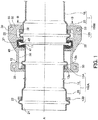
- Fig. 1 is a sectional view illustrating a state where two tubular structures 100 according to the embodiment (100A and 100B) are interconnected by sealing rubber 40 and a housing 30 being used.
- the tubular structure 100 according to the embodiment is used for a pipe jointing part for fluid feeding, the present invention is not limited thereto.
- the tubular structure 100 is provided with a tubular member 1 and a square ring 13 as a ring member disposed on the outer periphery of the tubular member 1.
- a steel pipe made of stainless steel (SUS304) or the like constitutes the tubular member 1.
- the tubular member 1 has a small diameter portion 10 and a large diameter portion 20 continuously disposed from one end of the small diameter portion 10.
- the end portion of the small diameter portion 10 that is on the side which is not continuous to the large diameter portion 20 is an insertion opening 11 connected to the large diameter portion 20 of another tubular member 1.
- a small diameter side annular protrusion 12 is formed by rolling processing using plastic deformation in the vicinity of an end portion of the insertion opening 11.
- the end portion of the large diameter portion 20 that is on the side which is not continuous to the small diameter portion 10 is a receiving opening 21 connected to the insertion opening 11 of another tubular member 1.
- a large diameter side annular protrusion 22 is formed by rolling processing using plastic deformation in the vicinity of an end portion of the receiving opening 21.
- the square ring 13 is provided with a small diameter side square ring 13A and a large diameter side square ring 13B.
- the small diameter side square ring 13A is inserted on the large diameter portion 20 side of the small diameter side annular protrusion 12 (side opposite to the insertion opening 11 as a tube end portion) on the outer periphery of the small diameter portion 10.
- the large diameter side square ring 13B is inserted on the small diameter portion 10 side of the large diameter side annular protrusion 22 (side opposite to the receiving opening 21 as a tube end portion) on the outer periphery of the large diameter portion 20.
- the small diameter side square ring 13A and the large diameter side square ring 13B will be collectively referred to as the square ring 13 in a case where the small diameter side square ring 13A and the large diameter side square ring 13B do not have to be particularly distinguished from each other.
- the material of the square ring 13 is, for example, stainless steel (SUS304). Although the material of the square ring 13 is not limited to stainless steel, it is preferable that the square ring 13 is as hard as or harder than the softer one of the housing 30 and the annular protrusions 12 and 22 (tubular member 1).
- the square ring 13 is softer than the housing 30 and the annular protrusions 12 and 22, the square ring 13 will be plastically deformed when a force is applied in the direction in which the two interconnected tubular structures 100A and 100B are separated from each other. Tube removal blocking performance may not be ensured due to this plastic deformation.
- the square ring 13 is an annular member that has a rectangular section.
- the square ring 13 according to the embodiment is a square ring that is obtained by a line member being curved in a circular shape and end portions thereof being welded.
- the present invention is not limited thereto and the end portions may also be in an unwelded state.
- the square ring 13 may also be manufactured by punching being performed on a plate member or by cutting of a casting that has a rough shape.
- the square ring 13 does not necessarily have to be a ring-shaped single-piece object and may also be, for example, a square ring divided into two. In this manner, the square ring 13 can be manufactured with higher accuracy than in a case where the square ring 13 is manufactured by casting.
- the square ring 13 has two side surfaces 13a and 13b that are parallel to each other and along a plane perpendicular to an axis A of the tubular member 1.
- the side surfaces may not be strictly perpendicular to the axis A.
- the square ring 13 When the thickness of the square ring 13 (distance between the side surface 13a and the side surface 13b) is less than 1 mm, the square ring 13 may be deformed and enter the clearance between the inner peripheral surface of the housing 30 and the inner peripheral surface of the tubular member 1. Accordingly, the square ring 13 preferably has a thickness of at least 1 mm and more preferably has a thickness of at least 2 mm.
- JWWA standards Japan Water Works Association standards
- G113 Japan Water Works Association standards
- the tubular structure 100 needs to have an elasticity of approximately plus-minus 1.0% with respect to the pipe length thereof.
- the square ring 13 is inserted into a groove (described later) in the housing along with the annular protrusion 12. Accordingly, when the square ring 13 is too thick, there is no room for relative movements of the housing 30 and the tubular structure 100. Then, elasticity cannot be ensured. Therefore, the square ring 13 preferably has a thickness of 4 mm or less.
- the height (radial-direction width) of the square ring 13 exceeds 2.5 mm, which is the maximum clearance between the inner peripheral surface of the housing 30 (inner peripheral surface of the part other than a groove portion) and the outer peripheral surface of the tubular member 1, and is preferably at least 3 mm.
- the height of the square ring 13 does not exceed 20 mm, which is the distance between a bottom portion of the groove (described later) formed in the housing 30 and the outer peripheral surface of the tubular member 1.
- the height of the square ring 13 is 8 mm.
- the clearance between the inner peripheral surface of the square ring 13 and the outer peripheral surface of the tubular member 1 is at least 0.2 mm, which is the minimum clearance allowing insertion into the outer peripheral surface of the tubular member 1.
- the clearance between the inner peripheral surface of the square ring 13 and the outer peripheral surface of the tubular member 1 is less than 2.5 mm, which is the maximum clearance of the inner peripheral surface (part other than the groove) of the housing 30.
- the clearance 30 between the inner peripheral surface of the square ring 13 and the outer peripheral surface of the tubular member 1 is 0.5 mm.
- the sealing rubber 40 is attached to the outer periphery of the portion where the two tubular structures 100 are interconnected.
- the sealing rubber 40 has two inner peripheral surfaces 41 and 42 facing the outer peripheral surface of the tubular member 1 and has a substantially U-shape in the section that illustrated in Fig. 1 .
- the present invention is not limited thereto and the shape may also be, for example, an L-shape.
- the diameter of the inner peripheral surface 41 which is one of the inner peripheral surfaces 41 and 42, is slightly smaller than the diameter of the outer peripheral surface of the small diameter portion 10, and the inner peripheral surface 41 comes into close contact with the outer peripheral surface of the small diameter portion 10 through elastic deformation once the inner peripheral surface 41 is disposed on the outer peripheral surface of the small diameter portion 10.
- the diameter of the other inner peripheral surface 42 is slightly smaller than the diameter of the outer peripheral surface of the large diameter portion 20, and the inner peripheral surface 42 comes into close contact with the outer peripheral surface of the large diameter portion 20 through elastic deformation once the inner peripheral surface 42 is disposed on the outer peripheral surface of the large diameter portion.
- the housing 30 is attached to the outer peripheral side of the sealing rubber 40.
- Fig. 2 is a sectional view of the housing 30, which is seen from the arrow B direction in Fig. 1 .
- the housing 30 is manufactured from the cast iron that is defined in Japanese Industrial Standards G 5502 FCD450.
- the housing 30 is made of cast iron as described above, and thus is larger in dimensional tolerance than the square ring 13, and the maximum clearance between the inner peripheral surface (part where no groove is formed) of the housing 30 and the outer peripheral surface of the tubular member 1 is approximately 2.5 mm.
- the housing 30 is provided with two semicircular members 30A and 30B.
- Each of the semicircular members 30A and 30B is provided with a semicircular ring portion 31 that is along the outer periphery of the tubular member 1 and two flange portions 32 that extend radially outward from both ends of the semicircular ring portion 31.
- a hole 33 is formed in each of the flange portions 32.
- the holes 33 formed in the flange portion 32 of the semicircular member 30A and the flange portion 32 of the semicircular member 30B allow penetration once the semicircular members 30A and 30B are disposed on the outer periphery of the tubular structure 100 and both flange portions 32 are allowed to face each other.
- a bolt 34 is inserted into the hole 33, and a nut 35 is screwed at the tip of the threaded portion of the bolt 34.
- the two semicircular members 30A and 30B cover the outer periphery of the tubular structure 100 and the two tubular structures 100 are interconnected.
- annular groove 36 covering the outer periphery of the annular protrusion 22 of the receiving opening 21, an annular groove 37 into which the sealing rubber 40 is fitted, and an annular groove 38 covering the annular protrusion 12 of the insertion opening 11 are formed in the inner peripheral surface of the housing 30.
- Figs. 3A and 3B are diagrams illustrating a method for manufacturing the tubular structure 100 according to the embodiment.
- Fig. 3A illustrates a state where the annular protrusion 12 is yet to be formed
- Fig. 3B illustrates a state where the annular protrusion 12 is already formed.
- Figs. 3A and 3B illustrate a method for attaching the small diameter side square ring 13A to the small diameter portion 10, which is a part of the method for manufacturing the tubular structure 100.
- the large diameter side square ring 13B is attached to the large diameter portion 20 by a method similar to the method for attaching the small diameter side square ring 13A to the small diameter portion 10. Accordingly, the two methods will not be distinguished from each other and will be described as a method for attaching the square ring 13 to the tubular member 1 in the following description.
- the square ring 13 is inserted into the outer periphery of the tubular member 1 in the state of Fig. 3A where the annular protrusion 12 is yet to be formed.
- annular protrusion 12 is manufactured by rolling processing as in Fig. 3B .
- Figs. 4A, 4B and 4C are diagrams illustrating a rolling processing method.
- Fig. 4A is a sectional view of a state prior to rolling processing in the direction that is perpendicular to the axis A of the tubular member 1.
- Fig. 4B is a sectional view along the axis A of the tubular member 1 and illustrates a pre-rolling processing state.
- Fig. 4C is a sectional view along the axis A of the tubular member 1 and illustrates a post-rolling processing state.
- a tube end portion (insertion opening 11) of the tubular member 1 is pinched between a convex roller 51 and a concave roller 52 as illustrated in Figs. 4A and 4B .
- the convex roller 51 and the concave roller 52 are rotated in this state. Then, the part that is pinched between the convex roller 51 and the concave roller 52 is also moved, and the annular protrusion 12 that is along a circumferential direction is formed on the tubular member 1 as illustrated in Fig. 4C .
- the tubular structure 100 can be manufactured that is provided with the tubular member 1 having the annular protrusion 12 and the square ring 13 disposed on the side opposite to the tube end portion (insertion opening 11) of the tubular member 1 with respect to the annular protrusion 12.
- the square ring When a square ring that is divided into two is used, the square ring can be attached after the annular protrusion 12 is formed.
- the sealing rubber 40 is inserted on the connection side, which is either the insertion opening 11 or the receiving opening 21, of one of the two tubular structures 100 scheduled to be interconnected.
- connection side which is either the insertion opening 11 or the receiving opening 21, of the other tubular structure 100 is inserted into the sealing rubber 40.
- the semicircular members 30A and 30B of the housing 30 are disposed on the outer periphery of the tubular structure 100, and the flange portion 32 of the semicircular member 30A and the flange portion 32 of the semicircular member 30B are allowed to face each other.
- the bolt 34 is inserted into the holes 33 formed in both flange portions 32, and the nut 35 is screwed at the tip of the threaded portion of the bolt 34.
- the two semicircular members 30A and 30B cover the outer periphery of the tubular structure 100 and the two tubular structures 100 are interconnected.
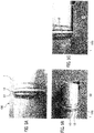
- Figs. 5A, 5B and 5C are pictures of the main part of the tubular structure 100
- Fig. 5A shows a state where the housing 30 is yet to be attached
- Fig. 5B shows a state where the semicircular member 30A of the housing 30 is disposed
- Fig. 5C is a picture in which Fig. 5B is partially enlarged.
- Fig. 6 is a graph showing the relationships between the release load (kN) and the height (mm) of the annular protrusion in the (A) and (B) cases above that the tubular structures according to the comparative example have.]
- the tubular member has a nominal diameter of 150A (actual diameter: ⁇ 165.2 mm, pipe thickness: 3.5 mm).
- the release load is the maximum load that can be borne when a force is applied in the direction in which the two tubular structures are separated from each other in a state where both tubular structures are interconnected by the housing being used.
- the load that is required as the release load in the case of actual use is 450 kN.
- a required load of 450 kN or less is not preferable in that the two tubular structures are easily removed in a case where, for example, a force is generated in the direction in which the two tubular structures are separated from each other due to an earthquake or the like in a state where the two tubular structures are interconnected.
- the release load is equal to or less than 450 kN, which is the required load, when the annular protrusion is approximately 4.7 mm or less in a case where the clearance is small (1.0 mm on one side). Accordingly, this is not preferable as a product.
- the release load is equal to or less than 450 kN, which is the required load, when the annular protrusion is approximately 7 mm or less in a case where the clearance is large (2.5 mm on one side). Accordingly, this is not preferable as a product.
- the release load is smaller in the (B) case where the clearance between the outer periphery of the tubular member and the inner periphery of the housing is large (2.5 mm on one side) than in the (A) case where the clearance between the outer periphery of the tubular member and the inner periphery of the housing is small (1.0 mm on one side).
- the housing is manufactured by casting. Casting entails a lot of manufacturing variations and results in an increase in clearance in some cases. Accordingly, the tubular structure according to the comparative example will be easily removed unless the annular protrusion is quite high.
- annular protrusion is formed by plastic deformation, an excessive increase in the height of the annular protrusion is not preferable from the viewpoint of ensuring strength.
- Fig. 7 is a graph showing the results in Table 1.
- Each of the square rings 13A and 13B has a height of 8 mm.
- the following three types were prepared as the tubular member 1 of the tubular structure 100 according to the embodiment.
- the tubular structures according to Comparative example (5) using no square ring reached a maximum load of 225 kN when the two tubular structures were pulled in the direction in which the tubular structures are separated from each other in the case of small clearance (1.0 mm on one side) and 3.5 mm in annular protrusion height. This is considered to be because the annular protrusion was too low and the housing climbed over the annular protrusion.
- the release load was at least a required load of 240 kN in any case (not only in the case of small clearance (1.0 mm on one side) but also in the case of large clearance (2.5 mm on one side)).
- the tubular structures according to Comparative example (5) using no square ring reached a maximum load of 430 kN when the two tubular structures were pulled in the direction in which the tubular structures are separated from each other in the case of small clearance (1.0 mm on one side) and in the case of 4 mm in annular protrusion height. This is considered to be because the annular protrusion was too low and the housing climbed over the annular protrusion.
- the release load was at least a required load of 450 kN in any case (not only in the case of small clearance (1.0 mm on one side) but also in the case of large clearance (2.5 mm on one side)).
- the tubular structures according to Comparative example (5) using no square ring reached a maximum load of 710 kN when the two tubular structures were pulled in the direction in which the tubular structures are separated from each other in the case of small clearance (1.0 mm on one side) and in the case of 4 mm in annular protrusion height. This is considered to be because the annular protrusion was too low and the housing climbed over the annular protrusion.
- the release load was at least a required load of 750 kN in any case (not only in the case of small clearance (1.0 mm on one side) but also in the case of large clearance (2.5 mm on one side)).
- the annular protrusions 12 and 22 are formed to be pinched between the two rollers 51 and 52, and thus have curved upper portions. Accordingly, the upper portions of the side surfaces of the annular protrusions 12 and 22 are not in contact with the inside surface of the housing 30 and do not contribute to tube removal prevention.
- the area of contact between the annular protrusions 12 and 22 and the inside surface of the housing 30 decreases once the clearance between the housing 30 and the outer peripheral surface of the tubular member 1 becomes large due to the manufacturing error of the housing 30. Then, the annular protrusions 12 and 22 easily enter the inner peripheral side of the housing 30 when a force is applied in the direction in which the tubular structures 100 are separated from each other with respect to the two tubular structures 100 interconnected by the housing 30.
- the square rings 13A and 13B have a rectangular section and have the two side surfaces 13a and 13b that are along a plane perpendicular to the axis of the tubular member 1.
- the square rings 13A and 13B are manufactured more accurately than the housing 30. Accordingly, no variation occurs in the area of contact with the side surfaces of the annular protrusions 12 and 22 perpendicular to the axis A and the area of contact can be reliably maintained.
- the side surfaces of the square rings 13A and 13B that are on the housing 30 side are also surfaces perpendicular to the axis A of the tubular member 1.
- the upper portions of the side surfaces of the square rings 13A and 13B are not curved whereas the upper portions of the annular protrusions 12 and 22 are curved. Accordingly, the upper portions of the side surfaces of the annular protrusions 12 and 22 are capable of ensuring the area of contact between the inside surface of the housing 30 and the side surfaces of the square rings 13A and 13B even when the clearance between the housing 30 and the side surface of the tubular member 1 becomes large due to the manufacturing error of the housing 30. Therefore, tube removal can be prevented.
- the present invention is not limited to the embodiment described above.
- the annular protrusions and the square rings 13A and 13B are disposed on both sides, that is, the insertion opening 11 side and the receiving opening 21 side, of the tubular structure 100 according to the embodiment.
- the present invention is not limited thereto and, for example, the annular protrusion and the square rings 13A and 13B may be disposed at the insertion opening 11 with the square rings 13A and 13B welded to the tubular member 1 without the annular protrusion being disposed at the receiving opening.
Landscapes
- Engineering & Computer Science (AREA)
- General Engineering & Computer Science (AREA)
- Mechanical Engineering (AREA)
- Physics & Mathematics (AREA)
- Fluid Mechanics (AREA)
- Rigid Pipes And Flexible Pipes (AREA)
- Joints Allowing Movement (AREA)
- Joints With Sleeves (AREA)
- Gasket Seals (AREA)
- Pipe Accessories (AREA)
- Fluid-Damping Devices (AREA)
Description
- The present invention relates to a tubular structure and a manufacturing method therefor.
- In the related art, ductile cast iron pipes are widely used as a tubular structure for water piping and so on. The ductile cast iron pipes are made of casting, and thus have a high degree of freedom in terms of shape. Accordingly, there are a wide variety of joints and the joints are used in the right places.
- In the meantime, tubular structures for water piping and so on also include stainless steel (SUS). However, SUS tubes have certain limited applications as processing the joints are not easy. Still, SUS tubes have the following advantages. SUS pipes are longer in service life than ductile cast iron pipes. SUS pipes are less prone to problems such as red water and blue water and cause no stress corrosion cracking under a normal temperature environment, and thus are low in running cost. Accordingly, the use of SUS tubes for various applications from now on is being demanded.
- Tubular structures made of SUS as described above are interconnected by the tube end portions of two tubular structures facing each other and a housing being disposed on the outer peripheries thereof.
- Annular protrusions are disposed at the tube end parts of the tubular structures. Two or more annular grooves are formed in the inner peripheral surface of the housing. When the housing is attached to the outer peripheries of the tubular structures, the annular protrusions of the two tubular structures to be interconnected are put into two of the annular grooves, respectively. Then, the housing is fixed to the tubular structures. As a result, the two tubular structures are interconnected (refer to Patent Document 1).
- However, in general, the housing is manufactured by casting. Casting entails a low level of dimensional accuracy, and thus results in a large clearance between the housing and the tubular structure in some cases. Once the clearance becomes large, the tubular structures interconnected by the housing are likely to be removed.
- Disclosed in this regard is a structure in which a ring for a stopper is disposed between the housing and the tubular structure (refer to Patent Document 2).
- According to this related art, the variations of the housing in terms of dimensional accuracy can be compensated for by the ring for a stopper even in a case where the clearance between the housing and the tubular structure is large.
- Patent Document 1: Japanese Patent No.
5727663 - Patent Document 2: Japanese Utility Model registration No.
3171067 -
JP 2004 347045 A - In the related art that is disclosed in
Patent Document 2, the ring for a stopper is equal in axial-direction length to the annular groove in the housing into which the ring for a stopper is inserted. The annular protrusion of the tubular structure is fitted tightly into a groove formed in the inner peripheral surface of the ring for a stopper. Accordingly, the housing and the tubular structure are fixed in an axial direction. Therefore, the length-direction shaking of the tubular structure is unlikely to be absorbed in a case where, for example, shaking occurs during an earthquake or the like. - An object of the present invention is to provide a tubular structure and a manufacturing method therefor that allow tube removal to be prevented even in a case where the clearance between a housing and the tubular structure is large and also allow length-direction vibration to be absorbed to some extent.
- A first aspect of the present invention relates to a tubular structure according to
claim 1, including a tubular member provided with annular protrusions on tube end portions and a ring member disposed on a side opposite to the tube end portion with respect to the annular protrusion on an outer periphery of the tubular member and having two side surfaces perpendicular to an axis of the tubular member. - According to the invention, one of the tube end portions of the tubular member is an insertion opening and the other tube end portion of the tubular member is a receiving opening larger in diameter than the insertion opening and the annular protrusion and the ring member are disposed on at least one of the insertion opening side and the receiving opening side.
- Preferably, the tubular structure is connectable by a housing having a groove into which the annular protrusion is inserted in an inner peripheral surface and a height of the ring member exceeds a maximum clearance between an outer peripheral surface of the tubular member and the inner peripheral surface of the housing and is less than a distance between the outer peripheral surface of the tubular member and a bottom surface of the groove.
- Preferably, a clearance between the outer peripheral surface of the tubular member and an inner peripheral surface of the ring member is at least a minimum clearance allowing insertion of the ring member into the outer periphery of the tubular member and is less than the maximum clearance between the outer peripheral surface of the tubular member and the inner peripheral surface of the housing.
- Preferably, the tubular member and the ring member are formed of stainless steel.
- A second aspect of the present invention relates to a method according to
claim 5 for manufacturing a tubular structure, the method including inserting a ring member into a tubular member and forming an annular protrusion at a part of the tubular member closer to a tube end portion than the ring member. - According to the present invention, a tubular structure and a manufacturing method therefor that allow tube removal to be prevented even in a case where the clearance between a housing and the tubular structure is large and also allow length-direction vibration to be absorbed to some extent can be provided.
-
-
Fig. 1 is a sectional view illustrating a state where two tubular structures according to an embodiment are interconnected by a housing being used. -
Fig. 2 is a sectional view of the housing, which is seen from the arrow B direction inFig. 1 . -
Fig. 3A is a diagram illustrating a method for manufacturing the tubular structure and illustrates a state where a small diameter side annular protrusion is yet to be formed, -
Fig. 3B is a diagram illustrating a method for manufacturing the tubular structure and illustrates a state where the small diameter side annular protrusion is already formed. -
Fig. 4A is a diagram illustrating a rolling processing method and a sectional view of a state prior to rolling processing in the direction that is perpendicular to an axis A of a small diameter portion -
Fig. 4B is a diagram illustrating a rolling processing method and a sectional view along the axis A of the small diameter portion and illustrates a pre-rolling processing state -
Fig. 4C is a diagram illustrating a rolling processing method and a sectional view along the axis A of the small diameter portion and illustrates a post-rolling processing state. -
Fig. 5A is picture of the main part of the tubular structure and shows a state where the housing is yet to be attached. -
Fig. 5B is picture of the main part of the tubular structure and shows a state where a semicircular member A of the housing is disposed. -
Fig. 5C is picture of the main part of the tubular structure and in whichFig. 5B is partially enlarged. -
Fig. 6 is a graph showing the relationship between a release load (kN) and the height of the annular protrusion that a tubular structure according to a comparative example has. -
Fig. 7A is a graph showing the results of an experiment regarding the tubular structure according to the present embodiment ofnominal diameter 80A. -
Fig. 7B is a graph showing the results of an experiment regarding the tubular structure according to the present embodiment ofnominal diameter 150A. -
Fig. 7C is a graph showing the results of an experiment regarding the tubular structure according to the present embodiment ofnominal diameter 250A. - Hereinafter, an embodiment of the present invention will be described with reference to drawings and the like.
-
Fig. 1 is a sectional view illustrating a state where twotubular structures 100 according to the embodiment (100A and 100B) are interconnected by sealingrubber 40 and ahousing 30 being used. Although thetubular structure 100 according to the embodiment is used for a pipe jointing part for fluid feeding, the present invention is not limited thereto. - The
tubular structure 100 according to the embodiment is provided with atubular member 1 and asquare ring 13 as a ring member disposed on the outer periphery of thetubular member 1. - A steel pipe made of stainless steel (SUS304) or the like constitutes the
tubular member 1. Thetubular member 1 has asmall diameter portion 10 and alarge diameter portion 20 continuously disposed from one end of thesmall diameter portion 10. - The end portion of the
small diameter portion 10 that is on the side which is not continuous to thelarge diameter portion 20 is aninsertion opening 11 connected to thelarge diameter portion 20 of anothertubular member 1. A small diameter sideannular protrusion 12 is formed by rolling processing using plastic deformation in the vicinity of an end portion of theinsertion opening 11. - The end portion of the
large diameter portion 20 that is on the side which is not continuous to thesmall diameter portion 10 is a receivingopening 21 connected to theinsertion opening 11 of anothertubular member 1. A large diameter sideannular protrusion 22 is formed by rolling processing using plastic deformation in the vicinity of an end portion of the receivingopening 21. - The
square ring 13 is provided with a small diameter sidesquare ring 13A and a large diameter sidesquare ring 13B. The small diameter sidesquare ring 13A is inserted on thelarge diameter portion 20 side of the small diameter side annular protrusion 12 (side opposite to theinsertion opening 11 as a tube end portion) on the outer periphery of thesmall diameter portion 10. The large diameter sidesquare ring 13B is inserted on thesmall diameter portion 10 side of the large diameter side annular protrusion 22 (side opposite to the receivingopening 21 as a tube end portion) on the outer periphery of thelarge diameter portion 20. In the following description, the small diameter sidesquare ring 13A and the large diameter sidesquare ring 13B will be collectively referred to as thesquare ring 13 in a case where the small diameter sidesquare ring 13A and the large diameter sidesquare ring 13B do not have to be particularly distinguished from each other. - The material of the
square ring 13 is, for example, stainless steel (SUS304). Although the material of thesquare ring 13 is not limited to stainless steel, it is preferable that thesquare ring 13 is as hard as or harder than the softer one of thehousing 30 and theannular protrusions 12 and 22 (tubular member 1). - If the
square ring 13 is softer than thehousing 30 and theannular protrusions square ring 13 will be plastically deformed when a force is applied in the direction in which the two interconnectedtubular structures - The
square ring 13 is an annular member that has a rectangular section. Thesquare ring 13 according to the embodiment is a square ring that is obtained by a line member being curved in a circular shape and end portions thereof being welded. However, the present invention is not limited thereto and the end portions may also be in an unwelded state. Thesquare ring 13 may also be manufactured by punching being performed on a plate member or by cutting of a casting that has a rough shape. Thesquare ring 13 does not necessarily have to be a ring-shaped single-piece object and may also be, for example, a square ring divided into two. In this manner, thesquare ring 13 can be manufactured with higher accuracy than in a case where thesquare ring 13 is manufactured by casting. - The
square ring 13 has twoside surfaces tubular member 1. The side surfaces may not be strictly perpendicular to the axis A. - When the thickness of the square ring 13 (distance between the
side surface 13a and theside surface 13b) is less than 1 mm, thesquare ring 13 may be deformed and enter the clearance between the inner peripheral surface of thehousing 30 and the inner peripheral surface of thetubular member 1. Accordingly, thesquare ring 13 preferably has a thickness of at least 1 mm and more preferably has a thickness of at least 2 mm. According to Japan Water Works Association standards (JWWA standards) G113, for example, thetubular structure 100 needs to have an elasticity of approximately plus-minus 1.0% with respect to the pipe length thereof. Thesquare ring 13 is inserted into a groove (described later) in the housing along with theannular protrusion 12. Accordingly, when thesquare ring 13 is too thick, there is no room for relative movements of thehousing 30 and thetubular structure 100. Then, elasticity cannot be ensured. Therefore, thesquare ring 13 preferably has a thickness of 4 mm or less. - The height (radial-direction width) of the
square ring 13 exceeds 2.5 mm, which is the maximum clearance between the inner peripheral surface of the housing 30 (inner peripheral surface of the part other than a groove portion) and the outer peripheral surface of thetubular member 1, and is preferably at least 3 mm. - Preferably, the height of the
square ring 13 does not exceed 20 mm, which is the distance between a bottom portion of the groove (described later) formed in thehousing 30 and the outer peripheral surface of thetubular member 1. - In the present embodiment, the height of the
square ring 13 is 8 mm. - Preferably, the clearance between the inner peripheral surface of the
square ring 13 and the outer peripheral surface of thetubular member 1 is at least 0.2 mm, which is the minimum clearance allowing insertion into the outer peripheral surface of thetubular member 1. - Preferably, the clearance between the inner peripheral surface of the
square ring 13 and the outer peripheral surface of thetubular member 1 is less than 2.5 mm, which is the maximum clearance of the inner peripheral surface (part other than the groove) of thehousing 30. - In the present embodiment, the
clearance 30 between the inner peripheral surface of thesquare ring 13 and the outer peripheral surface of thetubular member 1 is 0.5 mm. - The sealing
rubber 40 is attached to the outer periphery of the portion where the twotubular structures 100 are interconnected. - The sealing
rubber 40 has two innerperipheral surfaces tubular member 1 and has a substantially U-shape in the section that illustrated inFig. 1 . However, the present invention is not limited thereto and the shape may also be, for example, an L-shape. - The diameter of the inner
peripheral surface 41, which is one of the innerperipheral surfaces small diameter portion 10, and the innerperipheral surface 41 comes into close contact with the outer peripheral surface of thesmall diameter portion 10 through elastic deformation once the innerperipheral surface 41 is disposed on the outer peripheral surface of thesmall diameter portion 10. - The diameter of the other inner
peripheral surface 42 is slightly smaller than the diameter of the outer peripheral surface of thelarge diameter portion 20, and the innerperipheral surface 42 comes into close contact with the outer peripheral surface of thelarge diameter portion 20 through elastic deformation once the innerperipheral surface 42 is disposed on the outer peripheral surface of the large diameter portion. - The
housing 30 is attached to the outer peripheral side of the sealingrubber 40. -
Fig. 2 is a sectional view of thehousing 30, which is seen from the arrow B direction inFig. 1 . - In the present embodiment, the
housing 30 is manufactured from the cast iron that is defined in Japanese Industrial Standards G 5502 FCD450. Thehousing 30 is made of cast iron as described above, and thus is larger in dimensional tolerance than thesquare ring 13, and the maximum clearance between the inner peripheral surface (part where no groove is formed) of thehousing 30 and the outer peripheral surface of thetubular member 1 is approximately 2.5 mm. - As illustrated in
Fig. 2 , thehousing 30 is provided with twosemicircular members semicircular members semicircular ring portion 31 that is along the outer periphery of thetubular member 1 and twoflange portions 32 that extend radially outward from both ends of thesemicircular ring portion 31. - A
hole 33 is formed in each of theflange portions 32. Theholes 33 formed in theflange portion 32 of thesemicircular member 30A and theflange portion 32 of thesemicircular member 30B allow penetration once thesemicircular members tubular structure 100 and bothflange portions 32 are allowed to face each other. - A
bolt 34 is inserted into thehole 33, and anut 35 is screwed at the tip of the threaded portion of thebolt 34. By tightening of thenut 35, the twosemicircular members tubular structure 100 and the twotubular structures 100 are interconnected. - As illustrated in
Fig. 1 , anannular groove 36 covering the outer periphery of theannular protrusion 22 of the receivingopening 21, anannular groove 37 into which the sealingrubber 40 is fitted, and anannular groove 38 covering theannular protrusion 12 of theinsertion opening 11 are formed in the inner peripheral surface of thehousing 30. -
Figs. 3A and 3B are diagrams illustrating a method for manufacturing thetubular structure 100 according to the embodiment.Fig. 3A illustrates a state where theannular protrusion 12 is yet to be formed, andFig. 3B illustrates a state where theannular protrusion 12 is already formed.Figs. 3A and 3B illustrate a method for attaching the small diameter sidesquare ring 13A to thesmall diameter portion 10, which is a part of the method for manufacturing thetubular structure 100. The large diameter sidesquare ring 13B is attached to thelarge diameter portion 20 by a method similar to the method for attaching the small diameter sidesquare ring 13A to thesmall diameter portion 10. Accordingly, the two methods will not be distinguished from each other and will be described as a method for attaching thesquare ring 13 to thetubular member 1 in the following description. - Firstly, the
square ring 13 is inserted into the outer periphery of thetubular member 1 in the state ofFig. 3A where theannular protrusion 12 is yet to be formed. - Next, the
annular protrusion 12 is manufactured by rolling processing as inFig. 3B . -
Figs. 4A, 4B and 4C are diagrams illustrating a rolling processing method.Fig. 4A is a sectional view of a state prior to rolling processing in the direction that is perpendicular to the axis A of thetubular member 1.Fig. 4B is a sectional view along the axis A of thetubular member 1 and illustrates a pre-rolling processing state.Fig. 4C is a sectional view along the axis A of thetubular member 1 and illustrates a post-rolling processing state. - A tube end portion (insertion opening 11) of the
tubular member 1 is pinched between aconvex roller 51 and aconcave roller 52 as illustrated inFigs. 4A and 4B . - Then, one or both of the
convex roller 51 and theconcave roller 52 are relatively moved in the direction in which theconvex roller 51 and theconcave roller 52 approach each other. As a result, the part of thesmall diameter portion 10 that is pinched between theconvex roller 51 and theconcave roller 52 is deformed. - The
convex roller 51 and theconcave roller 52 are rotated in this state. Then, the part that is pinched between theconvex roller 51 and theconcave roller 52 is also moved, and theannular protrusion 12 that is along a circumferential direction is formed on thetubular member 1 as illustrated inFig. 4C . - In this manner, the
tubular structure 100 can be manufactured that is provided with thetubular member 1 having theannular protrusion 12 and thesquare ring 13 disposed on the side opposite to the tube end portion (insertion opening 11) of thetubular member 1 with respect to theannular protrusion 12. - When a square ring that is divided into two is used, the square ring can be attached after the
annular protrusion 12 is formed. - A method for connecting the
tubular structure 100 will be described. - Firstly, the sealing
rubber 40 is inserted on the connection side, which is either theinsertion opening 11 or the receivingopening 21, of one of the twotubular structures 100 scheduled to be interconnected. - Next, the connection side, which is either the
insertion opening 11 or the receivingopening 21, of the othertubular structure 100 is inserted into the sealingrubber 40. - The
semicircular members housing 30 are disposed on the outer periphery of thetubular structure 100, and theflange portion 32 of thesemicircular member 30A and theflange portion 32 of thesemicircular member 30B are allowed to face each other. - Then, the
bolt 34 is inserted into theholes 33 formed in bothflange portions 32, and thenut 35 is screwed at the tip of the threaded portion of thebolt 34. - By tightening of the
nut 35, the twosemicircular members tubular structure 100 and the twotubular structures 100 are interconnected. -
Figs. 5A, 5B and 5C are pictures of the main part of thetubular structure 100,Fig. 5A shows a state where thehousing 30 is yet to be attached,Fig. 5B shows a state where thesemicircular member 30A of thehousing 30 is disposed, andFig. 5C is a picture in whichFig. 5B is partially enlarged. - Before the effect of the
tubular structure 100 according to the embodiment is described, the annular protrusion height-release load relationships that tubular structures according to a comparative example, in which no square ring is attached to the tubular member, have in the following two cases will be described: - (A) Case where the clearance between the outer periphery of the tubular member and the inner periphery of the housing is as small as 1.0 mm on one side;
- (B) Case where the clearance between the outer periphery of the tubular member and the inner periphery of the housing is as large as 2.5 mm on one side.
-
Fig. 6 is a graph showing the relationships between the release load (kN) and the height (mm) of the annular protrusion in the (A) and (B) cases above that the tubular structures according to the comparative example have.] - The tubular member has a nominal diameter of 150A (actual diameter: ϕ165.2 mm, pipe thickness: 3.5 mm).
- The release load is the maximum load that can be borne when a force is applied in the direction in which the two tubular structures are separated from each other in a state where both tubular structures are interconnected by the housing being used.
- In the case of
nominal diameter 150A, the load that is required as the release load in the case of actual use (required load) is 450 kN. - A required load of 450 kN or less is not preferable in that the two tubular structures are easily removed in a case where, for example, a force is generated in the direction in which the two tubular structures are separated from each other due to an earthquake or the like in a state where the two tubular structures are interconnected.
- As illustrated in
Fig. 6 , the release load is equal to or less than 450 kN, which is the required load, when the annular protrusion is approximately 4.7 mm or less in a case where the clearance is small (1.0 mm on one side). Accordingly, this is not preferable as a product. - The release load is equal to or less than 450 kN, which is the required load, when the annular protrusion is approximately 7 mm or less in a case where the clearance is large (2.5 mm on one side). Accordingly, this is not preferable as a product. In addition, even at the same annular protrusion height, the release load is smaller in the (B) case where the clearance between the outer periphery of the tubular member and the inner periphery of the housing is large (2.5 mm on one side) than in the (A) case where the clearance between the outer periphery of the tubular member and the inner periphery of the housing is small (1.0 mm on one side).
- In other words, in a case where a force is generated in the direction in which the two tubular structures are separated from each other with respect to the two interconnected tubular structures according to the comparative example due to an earthquake or the like, the possibility that the two tubular structures are removed even with a small force occurs when the clearance is large and when the annular protrusion is not high to some extent.
- Usually, the housing is manufactured by casting. Casting entails a lot of manufacturing variations and results in an increase in clearance in some cases. Accordingly, the tubular structure according to the comparative example will be easily removed unless the annular protrusion is quite high.
- However, since the annular protrusion is formed by plastic deformation, an excessive increase in the height of the annular protrusion is not preferable from the viewpoint of ensuring strength.
- The relationship between the height of the
annular protrusion 12 and the release load was measured with regard to thetubular structure 100 according to the present embodiment, and the results of the measurement will be described based on Table 1 below.Fig. 7 is a graph showing the results in Table 1.[Table 1] Nominal diameter dimension (mm) Annular protrusion height (mm) Required load (kN) Embodiment Comparative example Width 1.0mm Width 2.0mm Width 4.0mm Large clearance (1) (One side 2.5mm) (2) Small clearance (3) (One side 1.0mm) (4) Small clearance (5)(One side 1.0mm) Release load (kN) Pass/fail Release load (kN) Pass/fail Release load (kN) Pass/fail Release load (kN) Pass/fail Release load Pass/fail (a) 80 (φ89.1 × t3.0) 3.5 240 240 ○ 272 ○ 293 ○ 295 ○ 225 × 5 273 302 335 340 255 ○ 6 291 325 361 365 275 7 275 303 340 344 260 10 260 285 320 325 245 12 242 276 298 300 230 × (b) 150 (φ 165.2 × t3.5) 4 450 455 520 560 570 430 × 6 524 578 630 645 490 ○ 8 580 638 700 712 540 10 560 624 671 680 520 18 468 533 568 570 445 × (c) 250 (φ 267.4 × t4.0) 4 750 753 855 920 925 710 × 6 801 913 990 995 760 ○ 9 955 1092 1185 1199 910 15 814 930 1001 1010 770 20 750 851 915 925 700 × - The following four types were prepared as the square rings 13A and 13B. Each of the square rings 13A and 13B has a height of 8 mm.
- (1) 1.0 mm in width, large clearance between the outer periphery of the
tubular member 1 and the inner periphery of the housing (2.5 mm on one side) - (2) 2.0 mm in width, large clearance between the outer periphery of the
tubular member 1 and the inner periphery of the housing (2.5 mm on one side) - (3) 2.0 mm in width, small clearance between the outer periphery of the
tubular member 1 and the inner periphery of the housing (1.0 mm on one side) - (4) 4.0 mm in width, small clearance between the outer periphery of the
tubular member 1 and the inner periphery of the housing (1.0 mm on one side) - (5) In addition, the tubular structure that uses no square ring was also prepared as the comparative example.
- Prepared as the height of the
annular protrusion 12 disposed on thetubular member 1 were six types (3.5, 5, 6, 7, 10, and 12 mm) in the case ofnominal diameter 80A, five types (4, 6, 8, 10, and 18 mm) in the case ofnominal diameter 150A, and five types (4, 6, 9, 15, and 20 mm) in the case ofnominal diameter 250A. - The following three types were prepared as the
tubular member 1 of thetubular structure 100 according to the embodiment. - (a)
Nominal diameter 80A (actual diameter: ϕ89.1 mm, pipe thickness: 3.0 mm) The required load at this time is 240 kN. - (b)
Nominal diameter 150A (actual diameter: ϕ165.2 mm, pipe thickness: 3.5 mm) The required load at this time is 450 kN. - (c)
Nominal diameter 250A (actual diameter: ϕ267.4 mm, pipe thickness: 4.0 mm) The required load at this time is 750 kN. - The tubular structures according to Comparative example (5) using no square ring reached a maximum load of 225 kN when the two tubular structures were pulled in the direction in which the tubular structures are separated from each other in the case of small clearance (1.0 mm on one side) and 3.5 mm in annular protrusion height. This is considered to be because the annular protrusion was too low and the housing climbed over the annular protrusion.
- In the case of 12 mm in annular protrusion height, the maximum load reached 230 kN when the two tubular structures were pulled in the direction in which the tubular structures are separated from each other. This is considered to be because the high annular protrusion led to a decline in strength attributable to an increase in plate thickness decrease and the annular protrusion was deformed by the housing.
- When it comes to (1) to (4) of the embodiment, the release load was at least a required load of 240 kN in any case (not only in the case of small clearance (1.0 mm on one side) but also in the case of large clearance (2.5 mm on one side)).
- The tubular structures according to Comparative example (5) using no square ring reached a maximum load of 430 kN when the two tubular structures were pulled in the direction in which the tubular structures are separated from each other in the case of small clearance (1.0 mm on one side) and in the case of 4 mm in annular protrusion height. This is considered to be because the annular protrusion was too low and the housing climbed over the annular protrusion.
- In the case of 18 mm in annular protrusion height, the maximum load reached 445 kN when the two tubular structures were pulled in the direction in which the tubular structures are separated from each other. This is considered to be because the high annular protrusion led to a decline in strength attributable to an increase in plate thickness decrease and the annular protrusion was deformed by the housing.
- When it comes to (1) to (4) of the embodiment, the release load was at least a required load of 450 kN in any case (not only in the case of small clearance (1.0 mm on one side) but also in the case of large clearance (2.5 mm on one side)).
- The tubular structures according to Comparative example (5) using no square ring reached a maximum load of 710 kN when the two tubular structures were pulled in the direction in which the tubular structures are separated from each other in the case of small clearance (1.0 mm on one side) and in the case of 4 mm in annular protrusion height. This is considered to be because the annular protrusion was too low and the housing climbed over the annular protrusion.
- In the case of 20 mm in annular protrusion height, the maximum load reached 700 kN when the two tubular structures were pulled in the direction in which the tubular structures are separated from each other. This is considered to be because the high annular protrusion led to a decline in strength attributable to an increase in plate thickness decrease and the annular protrusion was deformed by the housing.
- When it comes to (1) to (4) of the embodiment, the release load was at least a required load of 750 kN in any case (not only in the case of small clearance (1.0 mm on one side) but also in the case of large clearance (2.5 mm on one side)).
- (1) As described above, with the
tubular structure 100 according to the present embodiment, the release load becomes larger than in a case where the square rings 13A and 13B are not disposed and tube removal is unlikely to occur. - The
annular protrusions rollers annular protrusions housing 30 and do not contribute to tube removal prevention. - In the comparative example, the area of contact between the
annular protrusions housing 30 decreases once the clearance between thehousing 30 and the outer peripheral surface of thetubular member 1 becomes large due to the manufacturing error of thehousing 30. Then, theannular protrusions housing 30 when a force is applied in the direction in which thetubular structures 100 are separated from each other with respect to the twotubular structures 100 interconnected by thehousing 30. - In the present embodiment, however, the square rings 13A and 13B are attached.
- The square rings 13A and 13B have a rectangular section and have the two
side surfaces tubular member 1. - The square rings 13A and 13B are manufactured more accurately than the
housing 30. Accordingly, no variation occurs in the area of contact with the side surfaces of theannular protrusions - The side surfaces of the square rings 13A and 13B that are on the
housing 30 side are also surfaces perpendicular to the axis A of thetubular member 1. The upper portions of the side surfaces of the square rings 13A and 13B are not curved whereas the upper portions of theannular protrusions annular protrusions housing 30 and the side surfaces of the square rings 13A and 13B even when the clearance between thehousing 30 and the side surface of thetubular member 1 becomes large due to the manufacturing error of thehousing 30. Therefore, tube removal can be prevented. - (2) According to the present embodiment, the square rings 13A and 13B are disposed adjacent to the
annular protrusions annular protrusions annular protrusions tubular member 1. In addition, the square rings 13A and 13B are disposed adjacent to theannular protrusions - (3) The square rings 13A and 13B are not welded to the side surface of the
tubular member 1 and are capable of moving in the axis A direction with respect to thetubular member 1. Accordingly, the length-direction vibration of thetubular structure 100 can also be absorbed to some extent. Therefore, tube removal can be prevented even in a case where shaking occurs due to an earthquake or the like. - The present invention is not limited to the embodiment described above. For example, according to the above description, the annular protrusions and the square rings 13A and 13B are disposed on both sides, that is, the
insertion opening 11 side and the receivingopening 21 side, of thetubular structure 100 according to the embodiment. However, the present invention is not limited thereto and, for example, the annular protrusion and the square rings 13A and 13B may be disposed at theinsertion opening 11 with the square rings 13A and 13B welded to thetubular member 1 without the annular protrusion being disposed at the receiving opening. -
- 1
- Tubular member
- 10
- Small diameter portion
- 11
- Insertion opening
- 12
- Small diameter side annular protrusion
- 13
- Square ring
- 13a
- Side surface
- 13b
- Side surface
- 22
- Large diameter side annular protrusion
- 22
- Annular protrusion
- 23
- Large diameter side square ring
- 23a
- Side surface
- 23b
- Side surface
- 30
- Housing
- 36
- Annular groove
- 37
- Annular groove
- 38
- Annular groove
- 40
- Sealing rubber
- 41
- Inner peripheral surface
- 42
- Inner peripheral surface
- 100, 100A, 100B
- Tubular structure
Claims (5)
- A tubular structure comprising:a tubular member (1) provided with an annular protrusion (12, 22) on each of both tube end portions; andcorresponding ring members (13A, 13B) disposed respectively on a side opposite to each corresponding tube end portion with respect to the corresponding annular protrusion (12, 22) on an outer periphery of the tubular member, each ring member (13A, 13B) having two side surfaces (13a, 13b) perpendicular to an axis (A) of the tubular member,wherein one of the tube end portions of the tubular member (1) is an insertion opening (11) and the other tube end portion of the tubular member is a receiving opening (21) larger in diameter than the insertion opening (11).
- The tubular structure according to claim 1,
wherein the tubular structure is connectable by a housing (30) having a groove (36, 38) into which the annular protrusion (12, 22) is inserted in an inner peripheral surface, and
wherein a height of the ring member (13A, 13B) that corresponds to its width in radial direction
exceeds a maximum clearance between an outer peripheral surface of the tubular member (1) and an inner peripheral surface of the housing (30) at a part of the other than said groove and
is less than a distance between the outer peripheral surface of the tubular member (1) and a bottom surface of the groove (36, 38). - The tubular structure according to claim 2,
wherein a clearance between the outer peripheral surface of the tubular member (1) and an inner peripheral surface of the ring member (36, 38)
is at least a minimum clearance allowing insertion of the ring member (13A, 13B) into the outer periphery of the tubular member (1), and
is less than the maximum clearance between the outer peripheral surface of the tubular member (1) and the inner peripheral surface of the housing (30). - The tubular structure according to any one of claims 1 to 3,
wherein the tubular member (1) and the ring member (13A, 13B) are formed of stainless steel. - A method for manufacturing a tubular structure, in which one of tube end portions of a tubular member (1) is an insertion opening (11), and the other one of the tube end portions of the tubular member is a receiving opening (21) larger in diameter than the insertion opening (11), the method comprising:inserting respective ring members (13A, 13B) into each of an outer periphery of the insertion opening side of the tubular member (1), and an outer periphery of the receiving opening side of the tubular member, respectively, each ring member (13A, 13B) having two side surfaces (13a, 13b) perpendicular to an axis (A) of the tubular member; andforming respective annular protrusions (12, 22) at each part of the tubular member (1) closer to the respective tube end portion than the corresponding ring member (13A, 13B).
Applications Claiming Priority (2)
| Application Number | Priority Date | Filing Date | Title |
|---|---|---|---|
| JP2015211038A JP6422843B2 (en) | 2015-10-27 | 2015-10-27 | Tubular structure and manufacturing method thereof |
| PCT/JP2016/052799 WO2017073088A1 (en) | 2015-10-27 | 2016-01-29 | Tubular structure and manufacturing method therefor |
Publications (3)
| Publication Number | Publication Date |
|---|---|
| EP3369979A1 EP3369979A1 (en) | 2018-09-05 |
| EP3369979A4 EP3369979A4 (en) | 2018-11-07 |
| EP3369979B1 true EP3369979B1 (en) | 2020-03-11 |
Family
ID=58631612
Family Applications (1)
| Application Number | Title | Priority Date | Filing Date |
|---|---|---|---|
| EP16859326.7A Active EP3369979B1 (en) | 2015-10-27 | 2016-01-29 | Tubular structure and manufacturing method therefor |
Country Status (9)
| Country | Link |
|---|---|
| US (1) | US11098827B2 (en) |
| EP (1) | EP3369979B1 (en) |
| JP (1) | JP6422843B2 (en) |
| KR (1) | KR20180072802A (en) |
| CN (1) | CN108351056A (en) |
| MY (1) | MY188248A (en) |
| PH (1) | PH12018500901A1 (en) |
| TW (1) | TWI681142B (en) |
| WO (1) | WO2017073088A1 (en) |
Cited By (1)
| Publication number | Priority date | Publication date | Assignee | Title |
|---|---|---|---|---|
| US11313502B2 (en) * | 2016-12-07 | 2022-04-26 | Vestas Wind Systems A/S | Hose coupling |
Families Citing this family (6)
| Publication number | Priority date | Publication date | Assignee | Title |
|---|---|---|---|---|
| US11378208B2 (en) | 2016-12-14 | 2022-07-05 | ASC Engineered Solutions, LLC | Pipe couplings |
| JP6965594B2 (en) * | 2017-06-22 | 2021-11-10 | 日本製鉄株式会社 | Tubular structure |
| US11209107B2 (en) | 2017-07-28 | 2021-12-28 | ASC Engineered Solutions, LLC | Pre-assembled coupling assembly with cap |
| US11268638B2 (en) | 2017-07-28 | 2022-03-08 | ASC Engineered Solutions, LLC | Pre-assembled coupling assemblies with pipe fitting |
| US11448346B2 (en) | 2018-09-28 | 2022-09-20 | ASC Engineered Solutions, LLC | Pipe coupling |
| IT202000009817A1 (en) * | 2020-05-05 | 2021-11-05 | Pipes & Fittings Eqofluids S L | INTEGRATED JOINT SYSTEM FOR TUBULAR FLUID DISTRIBUTION ELEMENTS |
Citations (1)
| Publication number | Priority date | Publication date | Assignee | Title |
|---|---|---|---|---|
| JP3436864B2 (en) * | 1997-06-04 | 2003-08-18 | 株式会社栗本鐵工所 | Captive fittings |
Family Cites Families (37)
| Publication number | Priority date | Publication date | Assignee | Title |
|---|---|---|---|---|
| US2067428A (en) * | 1935-09-30 | 1937-01-12 | John W Wallis | Pipe coupling |
| US2497441A (en) * | 1945-03-19 | 1950-02-14 | Lockheed Aircraft Corp | Hydraulic coupling |
| US2781207A (en) * | 1953-01-12 | 1957-02-12 | Lockheed Aircraft Corp | Flexible couplings for beaded tubing |
| US2826437A (en) * | 1954-11-30 | 1958-03-11 | Lockheed Aircraft Corp | Flexible coupling for rigid beaded tubes |
| US2971781A (en) * | 1957-02-04 | 1961-02-14 | E B Wiggins Oil Tool Company I | Flexible coupling for beaded end tubing |
| US3223438A (en) * | 1960-06-20 | 1965-12-14 | Purolator Products Inc | Coupling |
| FR1291060A (en) * | 1961-03-10 | 1962-04-20 | Bronzavia Sa | Articulated connection for pipes |
| US3370870A (en) * | 1966-08-15 | 1968-02-27 | Gamah Corp | Flexible tubular coupling |
| US3405957A (en) * | 1967-04-03 | 1968-10-15 | Richard O. Chakroff | Flexible tube coupling |
| US3680894A (en) * | 1970-10-30 | 1972-08-01 | Victaulic Co Of America | Joints between pipes of different diameters and couplings and gaskets for the same |
| US3669472A (en) * | 1971-02-03 | 1972-06-13 | Wiggins Inc E B | Coupling device with spring locking detent means |
| JPS5727663A (en) | 1980-07-18 | 1982-02-15 | Toyoda Mach Works Ltd | Detector for limit of use of grindstone of grinder |
| US4436326A (en) * | 1981-07-13 | 1984-03-13 | Lockheed Corporation | Flexible coupling for fluid ducts |
| US4503680A (en) * | 1981-11-05 | 1985-03-12 | Allis-Chalmers Corp. | Attachment for exhaust pipe |
| JPS60121587U (en) * | 1984-01-21 | 1985-08-16 | 株式会社 ガスタ− | pipe connection device |
| JPS60121587A (en) * | 1984-11-09 | 1985-06-29 | Hitachi Ltd | Magnetic bubble memory element |
| GB8906949D0 (en) * | 1989-03-28 | 1989-05-10 | Marston Palmer Ltd | Coupling |
| US5584512A (en) * | 1993-10-07 | 1996-12-17 | Carstensen; Kenneth J. | Tubing interconnection system with different size snap ring grooves |
| JP2547706B2 (en) * | 1993-12-24 | 1996-10-23 | 通宏 藤原 | Sealing structure for connecting parts of tubular members |
| US5413046A (en) * | 1994-03-11 | 1995-05-09 | The Ensign-Bickford Company | Shock tube assembly |
| US6068303A (en) * | 1995-09-13 | 2000-05-30 | Hollnagle; Harold E. | Tube for connection to female socket |
| JP3494581B2 (en) * | 1998-12-15 | 2004-02-09 | 東亜高級継手バルブ製造株式会社 | Pipe fittings |
| JP2000257767A (en) | 1999-03-09 | 2000-09-19 | Taiyoo Joint Kk | Joint for pipe |
| JP2004347045A (en) * | 2003-05-23 | 2004-12-09 | Noora Engineering Kk | Expansion joint for stainless steel tube |
| US7086131B2 (en) * | 2004-05-14 | 2006-08-08 | Victaulic Company | Deformable mechanical pipe coupling |
| EP1909017A1 (en) * | 2005-07-12 | 2008-04-09 | Nippon Pillar Packing Co., Ltd. | Connection structure of stack panel to fluid device |
| JP4257319B2 (en) * | 2005-07-12 | 2009-04-22 | 日本ピラー工業株式会社 | Connection structure between integrated panel and fluidic device |
| CN100451422C (en) * | 2005-10-24 | 2009-01-14 | 沃恩工业股份有限公司 | Seal ring and joint and connection mechanism of steel pipe |
| JP2007225094A (en) * | 2006-02-27 | 2007-09-06 | Hitachi Metals Ltd | Coupling type joint |
| JP3171067U (en) * | 2011-08-01 | 2011-10-13 | ノーラエンジニアリング株式会社 | Stainless steel pipe joints for underground use |
| JP3171690U (en) * | 2011-09-02 | 2011-11-10 | ノーラエンジニアリング株式会社 | Stainless steel pipe joints for underground use |
| CN105074264B (en) * | 2013-04-26 | 2018-08-17 | 日立汽车系统株式会社 | cylinder and buffer |
| JP5727663B1 (en) | 2013-11-18 | 2015-06-03 | 日新製鋼株式会社 | Rolling method for joint of fluid feeding pipe and fluid feeding pipe |
| CN103925431B (en) * | 2014-03-31 | 2016-09-14 | 天津业和科技有限公司 | Polyethylene glass winding structure wall pipe and production method thereof |
| CN104405975A (en) | 2014-09-02 | 2015-03-11 | 吉林钰翎珑钢管钢构制造有限公司 | Steel pipe with bell and spigot joints |
| CN204554155U (en) * | 2015-02-27 | 2015-08-12 | 吉林钰翎珑钢管钢构制造有限公司 | Spigot and socket type telescopic pipe |
| US10859190B2 (en) * | 2016-05-16 | 2020-12-08 | Victaulic Company | Sprung coupling |
-
2015
- 2015-10-27 JP JP2015211038A patent/JP6422843B2/en active Active
-
2016
- 2016-01-29 CN CN201680064069.8A patent/CN108351056A/en active Pending
- 2016-01-29 EP EP16859326.7A patent/EP3369979B1/en active Active
- 2016-01-29 US US15/771,667 patent/US11098827B2/en active Active
- 2016-01-29 MY MYPI2018000580A patent/MY188248A/en unknown
- 2016-01-29 KR KR1020187014651A patent/KR20180072802A/en not_active Application Discontinuation
- 2016-01-29 WO PCT/JP2016/052799 patent/WO2017073088A1/en active Application Filing
- 2016-03-21 TW TW105108694A patent/TWI681142B/en not_active IP Right Cessation
-
2018
- 2018-04-26 PH PH12018500901A patent/PH12018500901A1/en unknown
Patent Citations (1)
| Publication number | Priority date | Publication date | Assignee | Title |
|---|---|---|---|---|
| JP3436864B2 (en) * | 1997-06-04 | 2003-08-18 | 株式会社栗本鐵工所 | Captive fittings |
Cited By (1)
| Publication number | Priority date | Publication date | Assignee | Title |
|---|---|---|---|---|
| US11313502B2 (en) * | 2016-12-07 | 2022-04-26 | Vestas Wind Systems A/S | Hose coupling |
Also Published As
| Publication number | Publication date |
|---|---|
| TWI681142B (en) | 2020-01-01 |
| JP6422843B2 (en) | 2018-11-14 |
| PH12018500901A1 (en) | 2018-11-05 |
| EP3369979A1 (en) | 2018-09-05 |
| EP3369979A4 (en) | 2018-11-07 |
| MY188248A (en) | 2021-11-24 |
| WO2017073088A1 (en) | 2017-05-04 |
| US11098827B2 (en) | 2021-08-24 |
| TW201715165A (en) | 2017-05-01 |
| US20190078710A1 (en) | 2019-03-14 |
| JP2017082891A (en) | 2017-05-18 |
| CN108351056A (en) | 2018-07-31 |
| KR20180072802A (en) | 2018-06-29 |
Similar Documents
| Publication | Publication Date | Title |
|---|---|---|
| EP3369979B1 (en) | Tubular structure and manufacturing method therefor | |
| US20240167592A1 (en) | Adapter Coupling | |
| US10145498B2 (en) | Flange joining structure and seal body used therein | |
| US7384076B2 (en) | Pipe ring apparatus and method | |
| KR20140130366A (en) | Method and structure for preventing slipping-off a tube in a pipe joint made of fluororesin | |
| US20070024007A1 (en) | Seal ring and method | |
| KR101512940B1 (en) | Pipe connecting apparatus for water service | |
| JP6955739B2 (en) | Pipe fitting | |
| JP2009281424A (en) | Metal gasket | |
| JP2008075841A (en) | Detachment preventing structure of pipe joint part | |
| JP6680559B2 (en) | Reinforcement jig for joint and mounting method of reinforcement jig | |
| JP6262544B2 (en) | Flange joint reinforcing structure and annular protective member used therefor | |
| JP6965594B2 (en) | Tubular structure | |
| JP2004347045A (en) | Expansion joint for stainless steel tube | |
| JP2005090605A (en) | Piping connector | |
| JP6605325B2 (en) | Tubular structure | |
| US20040188955A1 (en) | Ring-shaped metal gasket | |
| JP6935888B2 (en) | How to install the reinforcement jig | |
| JP6990913B2 (en) | Piping joint structure | |
| JP2021001626A (en) | Separation prevention structure of pipe connection portion | |
| US11584499B2 (en) | Integral personal watercraft shaft sealing axial alignment systems | |
| JPH0729355Y2 (en) | Pipe fitting | |
| JP7246440B2 (en) | How to attach the reinforcement jig | |
| JPS6383488A (en) | Pipe joint | |
| JP2016095029A (en) | Method for fastening seal washer and fluid pipe flange |
Legal Events
| Date | Code | Title | Description |
|---|---|---|---|
| STAA | Information on the status of an ep patent application or granted ep patent |
Free format text: STATUS: THE INTERNATIONAL PUBLICATION HAS BEEN MADE |
|
| PUAI | Public reference made under article 153(3) epc to a published international application that has entered the european phase |
Free format text: ORIGINAL CODE: 0009012 |
|
| STAA | Information on the status of an ep patent application or granted ep patent |
Free format text: STATUS: REQUEST FOR EXAMINATION WAS MADE |
|
| 17P | Request for examination filed |
Effective date: 20180427 |
|
| AK | Designated contracting states |
Kind code of ref document: A1 Designated state(s): AL AT BE BG CH CY CZ DE DK EE ES FI FR GB GR HR HU IE IS IT LI LT LU LV MC MK MT NL NO PL PT RO RS SE SI SK SM TR |
|
| AX | Request for extension of the european patent |
Extension state: BA ME |
|
| A4 | Supplementary search report drawn up and despatched |
Effective date: 20181009 |
|
| RIC1 | Information provided on ipc code assigned before grant |
Ipc: F16L 17/04 20060101ALN20181002BHEP Ipc: F16L 21/06 20060101AFI20181002BHEP Ipc: B21D 17/04 20060101ALN20181002BHEP Ipc: F16L 23/08 20060101ALI20181002BHEP |
|
| DAV | Request for validation of the european patent (deleted) | ||
| DAX | Request for extension of the european patent (deleted) | ||
| STAA | Information on the status of an ep patent application or granted ep patent |
Free format text: STATUS: EXAMINATION IS IN PROGRESS |
|
| 17Q | First examination report despatched |
Effective date: 20190509 |
|
| GRAP | Despatch of communication of intention to grant a patent |
Free format text: ORIGINAL CODE: EPIDOSNIGR1 |
|
| STAA | Information on the status of an ep patent application or granted ep patent |
Free format text: STATUS: GRANT OF PATENT IS INTENDED |
|
| RIC1 | Information provided on ipc code assigned before grant |
Ipc: F16L 17/04 20060101ALN20191104BHEP Ipc: F16L 21/06 20060101AFI20191104BHEP Ipc: B21D 17/04 20060101ALN20191104BHEP Ipc: F16L 23/08 20060101ALI20191104BHEP |
|
| INTG | Intention to grant announced |
Effective date: 20191126 |
|
| RIN1 | Information on inventor provided before grant (corrected) |
Inventor name: TOMIMURA, KOUKI Inventor name: NISHIJIMA, SHINNOSUKE |
|
| GRAS | Grant fee paid |
Free format text: ORIGINAL CODE: EPIDOSNIGR3 |
|
| RAP1 | Party data changed (applicant data changed or rights of an application transferred) |
Owner name: NIPPON STEEL NISSHIN CO., LTD. |
|
| GRAA | (expected) grant |
Free format text: ORIGINAL CODE: 0009210 |
|
| STAA | Information on the status of an ep patent application or granted ep patent |
Free format text: STATUS: THE PATENT HAS BEEN GRANTED |
|
| AK | Designated contracting states |
Kind code of ref document: B1 Designated state(s): AL AT BE BG CH CY CZ DE DK EE ES FI FR GB GR HR HU IE IS IT LI LT LU LV MC MK MT NL NO PL PT RO RS SE SI SK SM TR |
|
| REG | Reference to a national code |
Ref country code: GB Ref legal event code: FG4D |
|
| REG | Reference to a national code |
Ref country code: CH Ref legal event code: EP |
|
| REG | Reference to a national code |
Ref country code: AT Ref legal event code: REF Ref document number: 1243529 Country of ref document: AT Kind code of ref document: T Effective date: 20200315 |
|
| REG | Reference to a national code |
Ref country code: IE Ref legal event code: FG4D |
|
| REG | Reference to a national code |
Ref country code: DE Ref legal event code: R096 Ref document number: 602016031783 Country of ref document: DE |
|
| PG25 | Lapsed in a contracting state [announced via postgrant information from national office to epo] |
Ref country code: NO Free format text: LAPSE BECAUSE OF FAILURE TO SUBMIT A TRANSLATION OF THE DESCRIPTION OR TO PAY THE FEE WITHIN THE PRESCRIBED TIME-LIMIT Effective date: 20200611 Ref country code: FI Free format text: LAPSE BECAUSE OF FAILURE TO SUBMIT A TRANSLATION OF THE DESCRIPTION OR TO PAY THE FEE WITHIN THE PRESCRIBED TIME-LIMIT Effective date: 20200311 Ref country code: RS Free format text: LAPSE BECAUSE OF FAILURE TO SUBMIT A TRANSLATION OF THE DESCRIPTION OR TO PAY THE FEE WITHIN THE PRESCRIBED TIME-LIMIT Effective date: 20200311 |
|
| REG | Reference to a national code |
Ref country code: NL Ref legal event code: MP Effective date: 20200311 |
|
| PG25 | Lapsed in a contracting state [announced via postgrant information from national office to epo] |
Ref country code: HR Free format text: LAPSE BECAUSE OF FAILURE TO SUBMIT A TRANSLATION OF THE DESCRIPTION OR TO PAY THE FEE WITHIN THE PRESCRIBED TIME-LIMIT Effective date: 20200311 Ref country code: GR Free format text: LAPSE BECAUSE OF FAILURE TO SUBMIT A TRANSLATION OF THE DESCRIPTION OR TO PAY THE FEE WITHIN THE PRESCRIBED TIME-LIMIT Effective date: 20200612 Ref country code: SE Free format text: LAPSE BECAUSE OF FAILURE TO SUBMIT A TRANSLATION OF THE DESCRIPTION OR TO PAY THE FEE WITHIN THE PRESCRIBED TIME-LIMIT Effective date: 20200311 Ref country code: LV Free format text: LAPSE BECAUSE OF FAILURE TO SUBMIT A TRANSLATION OF THE DESCRIPTION OR TO PAY THE FEE WITHIN THE PRESCRIBED TIME-LIMIT Effective date: 20200311 Ref country code: BG Free format text: LAPSE BECAUSE OF FAILURE TO SUBMIT A TRANSLATION OF THE DESCRIPTION OR TO PAY THE FEE WITHIN THE PRESCRIBED TIME-LIMIT Effective date: 20200611 |
|
| REG | Reference to a national code |
Ref country code: LT Ref legal event code: MG4D |
|
| PG25 | Lapsed in a contracting state [announced via postgrant information from national office to epo] |
Ref country code: NL Free format text: LAPSE BECAUSE OF FAILURE TO SUBMIT A TRANSLATION OF THE DESCRIPTION OR TO PAY THE FEE WITHIN THE PRESCRIBED TIME-LIMIT Effective date: 20200311 |
|
| PG25 | Lapsed in a contracting state [announced via postgrant information from national office to epo] |
Ref country code: EE Free format text: LAPSE BECAUSE OF FAILURE TO SUBMIT A TRANSLATION OF THE DESCRIPTION OR TO PAY THE FEE WITHIN THE PRESCRIBED TIME-LIMIT Effective date: 20200311 Ref country code: SM Free format text: LAPSE BECAUSE OF FAILURE TO SUBMIT A TRANSLATION OF THE DESCRIPTION OR TO PAY THE FEE WITHIN THE PRESCRIBED TIME-LIMIT Effective date: 20200311 Ref country code: RO Free format text: LAPSE BECAUSE OF FAILURE TO SUBMIT A TRANSLATION OF THE DESCRIPTION OR TO PAY THE FEE WITHIN THE PRESCRIBED TIME-LIMIT Effective date: 20200311 Ref country code: IS Free format text: LAPSE BECAUSE OF FAILURE TO SUBMIT A TRANSLATION OF THE DESCRIPTION OR TO PAY THE FEE WITHIN THE PRESCRIBED TIME-LIMIT Effective date: 20200711 Ref country code: CZ Free format text: LAPSE BECAUSE OF FAILURE TO SUBMIT A TRANSLATION OF THE DESCRIPTION OR TO PAY THE FEE WITHIN THE PRESCRIBED TIME-LIMIT Effective date: 20200311 Ref country code: SK Free format text: LAPSE BECAUSE OF FAILURE TO SUBMIT A TRANSLATION OF THE DESCRIPTION OR TO PAY THE FEE WITHIN THE PRESCRIBED TIME-LIMIT Effective date: 20200311 Ref country code: PT Free format text: LAPSE BECAUSE OF FAILURE TO SUBMIT A TRANSLATION OF THE DESCRIPTION OR TO PAY THE FEE WITHIN THE PRESCRIBED TIME-LIMIT Effective date: 20200805 Ref country code: LT Free format text: LAPSE BECAUSE OF FAILURE TO SUBMIT A TRANSLATION OF THE DESCRIPTION OR TO PAY THE FEE WITHIN THE PRESCRIBED TIME-LIMIT Effective date: 20200311 |
|
| REG | Reference to a national code |
Ref country code: AT Ref legal event code: MK05 Ref document number: 1243529 Country of ref document: AT Kind code of ref document: T Effective date: 20200311 |
|
| REG | Reference to a national code |
Ref country code: DE Ref legal event code: R097 Ref document number: 602016031783 Country of ref document: DE |
|
| PLBE | No opposition filed within time limit |
Free format text: ORIGINAL CODE: 0009261 |
|
| STAA | Information on the status of an ep patent application or granted ep patent |
Free format text: STATUS: NO OPPOSITION FILED WITHIN TIME LIMIT |
|
| PG25 | Lapsed in a contracting state [announced via postgrant information from national office to epo] |
Ref country code: ES Free format text: LAPSE BECAUSE OF FAILURE TO SUBMIT A TRANSLATION OF THE DESCRIPTION OR TO PAY THE FEE WITHIN THE PRESCRIBED TIME-LIMIT Effective date: 20200311 Ref country code: DK Free format text: LAPSE BECAUSE OF FAILURE TO SUBMIT A TRANSLATION OF THE DESCRIPTION OR TO PAY THE FEE WITHIN THE PRESCRIBED TIME-LIMIT Effective date: 20200311 Ref country code: AT Free format text: LAPSE BECAUSE OF FAILURE TO SUBMIT A TRANSLATION OF THE DESCRIPTION OR TO PAY THE FEE WITHIN THE PRESCRIBED TIME-LIMIT Effective date: 20200311 Ref country code: IT Free format text: LAPSE BECAUSE OF FAILURE TO SUBMIT A TRANSLATION OF THE DESCRIPTION OR TO PAY THE FEE WITHIN THE PRESCRIBED TIME-LIMIT Effective date: 20200311 |
|
| 26N | No opposition filed |
Effective date: 20201214 |
|
| PG25 | Lapsed in a contracting state [announced via postgrant information from national office to epo] |
Ref country code: PL Free format text: LAPSE BECAUSE OF FAILURE TO SUBMIT A TRANSLATION OF THE DESCRIPTION OR TO PAY THE FEE WITHIN THE PRESCRIBED TIME-LIMIT Effective date: 20200311 Ref country code: SI Free format text: LAPSE BECAUSE OF FAILURE TO SUBMIT A TRANSLATION OF THE DESCRIPTION OR TO PAY THE FEE WITHIN THE PRESCRIBED TIME-LIMIT Effective date: 20200311 |
|
| REG | Reference to a national code |
Ref country code: DE Ref legal event code: R119 Ref document number: 602016031783 Country of ref document: DE |
|
| PG25 | Lapsed in a contracting state [announced via postgrant information from national office to epo] |
Ref country code: MC Free format text: LAPSE BECAUSE OF FAILURE TO SUBMIT A TRANSLATION OF THE DESCRIPTION OR TO PAY THE FEE WITHIN THE PRESCRIBED TIME-LIMIT Effective date: 20200311 |
|
| REG | Reference to a national code |
Ref country code: CH Ref legal event code: PL |
|
| GBPC | Gb: european patent ceased through non-payment of renewal fee |
Effective date: 20210129 |
|
| PG25 | Lapsed in a contracting state [announced via postgrant information from national office to epo] |
Ref country code: LU Free format text: LAPSE BECAUSE OF NON-PAYMENT OF DUE FEES Effective date: 20210129 |
|
| REG | Reference to a national code |
Ref country code: BE Ref legal event code: MM Effective date: 20210131 |
|
| PG25 | Lapsed in a contracting state [announced via postgrant information from national office to epo] |
Ref country code: FR Free format text: LAPSE BECAUSE OF NON-PAYMENT OF DUE FEES Effective date: 20210131 |
|
| PG25 | Lapsed in a contracting state [announced via postgrant information from national office to epo] |
Ref country code: GB Free format text: LAPSE BECAUSE OF NON-PAYMENT OF DUE FEES Effective date: 20210129 Ref country code: LI Free format text: LAPSE BECAUSE OF NON-PAYMENT OF DUE FEES Effective date: 20210131 Ref country code: CH Free format text: LAPSE BECAUSE OF NON-PAYMENT OF DUE FEES Effective date: 20210131 Ref country code: DE Free format text: LAPSE BECAUSE OF NON-PAYMENT OF DUE FEES Effective date: 20210803 |
|
| PG25 | Lapsed in a contracting state [announced via postgrant information from national office to epo] |
Ref country code: IE Free format text: LAPSE BECAUSE OF NON-PAYMENT OF DUE FEES Effective date: 20210129 |
|
| PG25 | Lapsed in a contracting state [announced via postgrant information from national office to epo] |
Ref country code: BE Free format text: LAPSE BECAUSE OF NON-PAYMENT OF DUE FEES Effective date: 20210131 |
|
| PG25 | Lapsed in a contracting state [announced via postgrant information from national office to epo] |
Ref country code: CY Free format text: LAPSE BECAUSE OF FAILURE TO SUBMIT A TRANSLATION OF THE DESCRIPTION OR TO PAY THE FEE WITHIN THE PRESCRIBED TIME-LIMIT Effective date: 20200311 |
|
| PG25 | Lapsed in a contracting state [announced via postgrant information from national office to epo] |
Ref country code: HU Free format text: LAPSE BECAUSE OF FAILURE TO SUBMIT A TRANSLATION OF THE DESCRIPTION OR TO PAY THE FEE WITHIN THE PRESCRIBED TIME-LIMIT; INVALID AB INITIO Effective date: 20160129 |
|
| PG25 | Lapsed in a contracting state [announced via postgrant information from national office to epo] |
Ref country code: MK Free format text: LAPSE BECAUSE OF FAILURE TO SUBMIT A TRANSLATION OF THE DESCRIPTION OR TO PAY THE FEE WITHIN THE PRESCRIBED TIME-LIMIT Effective date: 20200311 |