EP3369928B1 - Hydraulic pressure intensifier - Google Patents
Hydraulic pressure intensifier Download PDFInfo
- Publication number
- EP3369928B1 EP3369928B1 EP17159046.6A EP17159046A EP3369928B1 EP 3369928 B1 EP3369928 B1 EP 3369928B1 EP 17159046 A EP17159046 A EP 17159046A EP 3369928 B1 EP3369928 B1 EP 3369928B1
- Authority
- EP
- European Patent Office
- Prior art keywords
- pressure
- pilot valve
- control
- valve
- pressure chamber
- Prior art date
- Legal status (The legal status is an assumption and is not a legal conclusion. Google has not performed a legal analysis and makes no representation as to the accuracy of the status listed.)
- Active
Links
- 239000012530 fluid Substances 0.000 description 14
- 238000010276 construction Methods 0.000 description 3
- 230000003247 decreasing effect Effects 0.000 description 3
- 230000009286 beneficial effect Effects 0.000 description 1
- 238000003754 machining Methods 0.000 description 1
- 230000004048 modification Effects 0.000 description 1
- 238000012986 modification Methods 0.000 description 1
- 230000007935 neutral effect Effects 0.000 description 1
Images

Classifications
-
- F—MECHANICAL ENGINEERING; LIGHTING; HEATING; WEAPONS; BLASTING
- F04—POSITIVE - DISPLACEMENT MACHINES FOR LIQUIDS; PUMPS FOR LIQUIDS OR ELASTIC FLUIDS
- F04B—POSITIVE-DISPLACEMENT MACHINES FOR LIQUIDS; PUMPS
- F04B7/00—Piston machines or pumps characterised by having positively-driven valving
- F04B7/02—Piston machines or pumps characterised by having positively-driven valving the valving being fluid-actuated
- F04B7/0208—Piston machines or pumps characterised by having positively-driven valving the valving being fluid-actuated the distribution member forming both the inlet and discharge distributor for one single pumping chamber
- F04B7/0225—Piston machines or pumps characterised by having positively-driven valving the valving being fluid-actuated the distribution member forming both the inlet and discharge distributor for one single pumping chamber and having a slidable movement
-
- F—MECHANICAL ENGINEERING; LIGHTING; HEATING; WEAPONS; BLASTING
- F15—FLUID-PRESSURE ACTUATORS; HYDRAULICS OR PNEUMATICS IN GENERAL
- F15B—SYSTEMS ACTING BY MEANS OF FLUIDS IN GENERAL; FLUID-PRESSURE ACTUATORS, e.g. SERVOMOTORS; DETAILS OF FLUID-PRESSURE SYSTEMS, NOT OTHERWISE PROVIDED FOR
- F15B3/00—Intensifiers or fluid-pressure converters, e.g. pressure exchangers; Conveying pressure from one fluid system to another, without contact between the fluids
-
- F—MECHANICAL ENGINEERING; LIGHTING; HEATING; WEAPONS; BLASTING
- F04—POSITIVE - DISPLACEMENT MACHINES FOR LIQUIDS; PUMPS FOR LIQUIDS OR ELASTIC FLUIDS
- F04B—POSITIVE-DISPLACEMENT MACHINES FOR LIQUIDS; PUMPS
- F04B9/00—Piston machines or pumps characterised by the driving or driven means to or from their working members
- F04B9/08—Piston machines or pumps characterised by the driving or driven means to or from their working members the means being fluid
- F04B9/10—Piston machines or pumps characterised by the driving or driven means to or from their working members the means being fluid the fluid being liquid
- F04B9/103—Piston machines or pumps characterised by the driving or driven means to or from their working members the means being fluid the fluid being liquid having only one pumping chamber
- F04B9/105—Piston machines or pumps characterised by the driving or driven means to or from their working members the means being fluid the fluid being liquid having only one pumping chamber reciprocating movement of the pumping member being obtained by a double-acting liquid motor
- F04B9/1056—Piston machines or pumps characterised by the driving or driven means to or from their working members the means being fluid the fluid being liquid having only one pumping chamber reciprocating movement of the pumping member being obtained by a double-acting liquid motor with fluid-actuated inlet or outlet valve
-
- F—MECHANICAL ENGINEERING; LIGHTING; HEATING; WEAPONS; BLASTING
- F04—POSITIVE - DISPLACEMENT MACHINES FOR LIQUIDS; PUMPS FOR LIQUIDS OR ELASTIC FLUIDS
- F04B—POSITIVE-DISPLACEMENT MACHINES FOR LIQUIDS; PUMPS
- F04B9/00—Piston machines or pumps characterised by the driving or driven means to or from their working members
- F04B9/08—Piston machines or pumps characterised by the driving or driven means to or from their working members the means being fluid
- F04B9/10—Piston machines or pumps characterised by the driving or driven means to or from their working members the means being fluid the fluid being liquid
- F04B9/109—Piston machines or pumps characterised by the driving or driven means to or from their working members the means being fluid the fluid being liquid having plural pumping chambers
- F04B9/111—Piston machines or pumps characterised by the driving or driven means to or from their working members the means being fluid the fluid being liquid having plural pumping chambers with two mechanically connected pumping members
- F04B9/113—Piston machines or pumps characterised by the driving or driven means to or from their working members the means being fluid the fluid being liquid having plural pumping chambers with two mechanically connected pumping members reciprocating movement of the pumping members being obtained by a double-acting liquid motor
-
- F—MECHANICAL ENGINEERING; LIGHTING; HEATING; WEAPONS; BLASTING
- F15—FLUID-PRESSURE ACTUATORS; HYDRAULICS OR PNEUMATICS IN GENERAL
- F15B—SYSTEMS ACTING BY MEANS OF FLUIDS IN GENERAL; FLUID-PRESSURE ACTUATORS, e.g. SERVOMOTORS; DETAILS OF FLUID-PRESSURE SYSTEMS, NOT OTHERWISE PROVIDED FOR
- F15B15/00—Fluid-actuated devices for displacing a member from one position to another; Gearing associated therewith
- F15B15/20—Other details, e.g. assembly with regulating devices
- F15B15/202—Externally-operated valves mounted in or on the actuator
-
- F—MECHANICAL ENGINEERING; LIGHTING; HEATING; WEAPONS; BLASTING
- F04—POSITIVE - DISPLACEMENT MACHINES FOR LIQUIDS; PUMPS FOR LIQUIDS OR ELASTIC FLUIDS
- F04B—POSITIVE-DISPLACEMENT MACHINES FOR LIQUIDS; PUMPS
- F04B2201/00—Pump parameters
- F04B2201/08—Cylinder or housing parameters
- F04B2201/0808—Size of the dead volume
-
- F—MECHANICAL ENGINEERING; LIGHTING; HEATING; WEAPONS; BLASTING
- F04—POSITIVE - DISPLACEMENT MACHINES FOR LIQUIDS; PUMPS FOR LIQUIDS OR ELASTIC FLUIDS
- F04B—POSITIVE-DISPLACEMENT MACHINES FOR LIQUIDS; PUMPS
- F04B2205/00—Fluid parameters
- F04B2205/06—Pressure in a (hydraulic) circuit
- F04B2205/065—Pressure in a (hydraulic) circuit between two stages in a multi-stage pump
-
- F—MECHANICAL ENGINEERING; LIGHTING; HEATING; WEAPONS; BLASTING
- F04—POSITIVE - DISPLACEMENT MACHINES FOR LIQUIDS; PUMPS FOR LIQUIDS OR ELASTIC FLUIDS
- F04B—POSITIVE-DISPLACEMENT MACHINES FOR LIQUIDS; PUMPS
- F04B2205/00—Fluid parameters
- F04B2205/16—Opening or closing of a valve in a circuit
-
- F—MECHANICAL ENGINEERING; LIGHTING; HEATING; WEAPONS; BLASTING
- F15—FLUID-PRESSURE ACTUATORS; HYDRAULICS OR PNEUMATICS IN GENERAL
- F15B—SYSTEMS ACTING BY MEANS OF FLUIDS IN GENERAL; FLUID-PRESSURE ACTUATORS, e.g. SERVOMOTORS; DETAILS OF FLUID-PRESSURE SYSTEMS, NOT OTHERWISE PROVIDED FOR
- F15B2215/00—Fluid-actuated devices for displacing a member from one position to another
- F15B2215/30—Constructional details thereof
Definitions
- the present invention relates to a hydraulic pressure intensifier comprising a housing having a low pressure chamber and a high pressure chamber, force transmitting means between the low pressure chamber and the high pressure chamber, and a switching valve connecting the low pressure chamber to a first pressure or to a second pressure different from the first pressure, and being controlled by a pilot valve, wherein the switching valve comprises a valve element having a first control pressure area and a second control pressure area, wherein the pilot valve controls a pressure difference between the first control pressure area and the second control pressure area.
- US 4 780 064 A describes a hydraulic pressure intensifier comprising a housing having a low pressure chamber and a high pressure chamber on both sides of plungers force transmitting means between the low pressure chamber and the high pressure chamber, and a switching valve connecting the low pressure chamber to a first pressure or to a second pressure different from the first pressure, wherein the switching valve is controlled by a pilot valve.
- the switching valve comprises a valve element having a first control pressure area and a second control pressure area wherein the pilot valve controls a pressure difference between the first control pressure area and a second control pressure area.
- DE 30 32 430 A1 describes a device for increasing a pressure of a fluid for a consumer.
- the device comprises a low pressure chamber and a high pressure chamber as well as force transmitting means between the low pressure chamber and the high pressure chamber and a switching valve connecting the low pressure chamber to a first pressure or to a second pressure different from the first pressure, wherein the switching valve is controlled by a pilot valve arrangement.
- Another pressure intensifier is known, for example, from US 6 866 485 B2 .
- the force transmitting means can be, for example, in the form of a stepped piston having a larger low pressure area in the low pressure chamber and a smaller high pressure area in the high pressure chamber.
- the piston When the low pressure area is loaded with a supply pressure, the piston is shifted in a direction to decrease the volume of the high pressure chamber.
- the pressure in the high pressure chamber is increased and the fluid with the increased pressure is outputted.
- the second half of the cycle the low pressure in the low pressure chamber is lowered so that the supply pressure which is guided into the high pressure chamber can push the piston back to its initial position.
- the change of the pressure in the low pressure chamber is performed by means of the switching valve. Such a cycle is repeated. In each cycle a certain amount of fluid under high pressure can be outputted from the high pressure chamber.
- the object underlying the invention is to have a large volume output on the high pressure side of the pressure intensifier.
- valve element of the switching valve comprises a flange extending radially, wherein the control pressure areas are located on opposite faces of the flange.
- the switching valve When the switching valve is controlled by a pilot valve, the switching valve can be made larger.
- a larger switching valve allows for a larger volume flow into and out of the low pressure chamber.
- the pilot valve can be made very small and thereby very small hydraulic losses are created.
- the control of a pressure difference is a very simple operation. In this case the pilot valve can have a very simple construction.
- the pressure areas are kept outside of the low pressure chamber.
- valve element is located in the low pressure chamber. There is no further channel between the switching valve and the low pressure chamber. Hydraulic losses can be kept small.
- valve element comprises an outer diameter corresponding to an outer diameter of a low pressure portion of the force transmitting means.
- the housing comprises control channels for supplying pilot pressure to the control pressure areas and supply channels for supplying pressure to the low pressure chamber, wherein the control channels have a smaller cross sectional area than the supply channels.
- the control channels can be kept small.
- the supply channels have a larger cross section, the flow resistance in such supply channels is low and the filling and emptying of the low pressure chamber can be performed in a short time.
- the pressures acting on the control pressure areas are switched by the pilot valve between the first pressure and the second pressure.
- the pilot valve between the first pressure and the second pressure.
- only two pressures are necessary on the low pressure side of the pressure intensifier.
- These pressures can be, for example, supply pressure and tank pressure.
- the pilot valve is controlled by the force transmitting means. Depending on the position of the force transmitting means the pilot valve generates a pressure difference in one or in another direction.
- the pilot valve is pressure controlled.
- the pressure can, in turn, be controlled by the position of the force transmitting means.
- the pilot valve is electrically controlled.
- the pilot valve can comprise, for example, a solenoid which drives a pilot valve element of the pilot valve.
- the pilot valve is connected to a controller, wherein the controller comprises a counter counting strokes of the pilot valve and/or of the switching valve.
- the controller comprises a counter counting strokes of the pilot valve and/or of the switching valve.
- a pressure intensifier is part of a piston-cylinder-arrangement.
- two piston-cylinder-arrangements are used in connection with some kind of load which is controlled by a number of such arrangements with integrated intensifiers, it is possible to keep the load horizontal. This can be done without any form of feedback from a positioning sensor of the load or something similar.
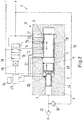
- a hydraulic pressure intensifier 1 comprises a housing 2 having a low pressure chamber 3 and a high pressure chamber 4.
- Force transmitting means in form of a stepped piston 5 are located between the low pressure chamber 3 and the high pressure chamber 4.
- a piston 5 comprises a low pressure area 6 in the low pressure chamber 3 and a high pressure area 7 in the high pressure chamber 4.
- a switching valve 8 comprises a valve element 9 which is located in the low pressure chamber 3.
- the valve element 9 comprises a radially extending flange 10 which extends into a groove 11 of the housing 2.
- the groove 11 has a slightly larger inner diameter than the low pressure chamber 3.
- the flange 10 forms a first control pressure area 12 and a second control pressure area 13.
- the first control pressure area 12 receives hydraulic fluid from a first control channel 14 in the housing and the second control pressure area 13 receives hydraulic fluid under pressure from a second control channel 15 in the housing.
- the valve element 9 is shown in a "neutral" position.
- valve element 9 In a first end position, when the valve element 9 is shifted to the right, i.e. away from the piston 5, it opens an opening of a first supply channel 16 in the housing. In the opposite end position it opens an opening of a second supply channel 17 in the housing 2.
- the pressure intensifier 1 has a supply pressure port P and a tank pressure port T.
- Pressures in the control channels 14, 15 are controlled by a pilot valve 18.
- the supply pressure port P is connected to the first control channel 14 and the second control channel 15 is connected to the tank port T.
- the second control channel 15 is connected to the supply pressure port P and the first control channel 14 is connected to the tank port T.
- the first supply channel 16 is permanently connected to the tank port T and the second supply channel 17 is permanently connected to the supply pressure port P.
- the supply pressure port P is connected to the high pressure chamber 4 via a first check valve 19 opening in a direction towards the high pressure chamber 4.
- the high pressure chamber 4 is connected to a high pressure output H via a second check valve 20 opening in a direction towards the high pressure output H.
- a switching channel 21 opens into the high pressure chamber 4.
- This switching channel 21 is connected to a first pressure area 22 of the pilot valve 18.
- the pilot valve 18 comprises furthermore a second pressure area 23 which is permanently connected to the supply pressure port P.
- the first pressure area 22 is larger than the second pressure area 23.
- the piston 5 comprises a high pressure portion 24 and a low pressure portion 25.
- a longitudinal groove 26 is provided on the high pressure portion 24 at a predetermined distance away from the high pressure area 7. This groove 26 is connected to an intermediate space 27 which is permanently connected to the tank port T.
- the intermediate space 27 is increased when the piston 5 moves in a direction towards the valve element 9 and is decreased when piston 5 moves in the opposite direction.
- the longitudinal groove 26 comes in overlapping relation with the switching channel 21 and connects the switching channel 21 to the intermediate space 27.
- the supply pressure from the supply pressure port P reaches the first pressure area 22 of the pilot valve 18. Since the first pressure area 22 is larger than the second pressure area 23 on which the same pressure acts the position of the pilot valve 18 is changed. Now the second control pressure area 13 is loaded by the supply pressure of the supply pressure port P and the first control pressure area 12 is connected to the tank port T. A pressure difference exists between the two control pressure areas 12, 13 shifting the valve element 9 of the switching valve 8 in a direction towards the piston 5. This movement closes the first supply channel 16 and opens the second supply channel 17. Since the second supply channel 17 is connected to the supply pressure port P the supply pressure reaches the low pressure chamber 3.
- the supply channels 16, 17 can have a much larger area than the control channels 12, 13 and consequently a much lower flow resistance. Furthermore, the switching valve 8 can be made rather large so that the low pressure chamber 3 can be filled with hydraulic fluid from the supply pressure port P in a rather short time. The same is true for the removal of hydraulic fluid via the first supply channel 16. Therefore, it is possible to increase the frequency of the pressure intensifier 1.
- the pilot valve 18 can be made very small and thereby very small hydraulic losses are created.
- the pilot valve 18 can be driven with very low pressures, for example, 13 bar or even less.
- the valve element 9 can be located in the same bore which forms the low pressure chamber 3. It can have the same outer diameter (apart from the flange 10) as the piston 9 so that machining of the housing 2 is facilitated.
- Fig. 2 shows a slightly modified embodiment of a hydraulic pressure intensifier 1. The same reference numerals are used for the same elements as in Fig. 1 .
- the pilot valve 18 is not hydraulically driven, as in the embodiment shown in Fig. 1 .
- the pilot valve 18 comprises an electric drive 28, for example, a solenoid.
- the electric drive 28 is connected to a controller 29.
- the controller 29 controls the operation of the electric drive 28 and therefore the position of the pilot valve 18.
- a first sensor 30 is connected to the controller 29.
- the first sensor 30 detects the end of the working stroke of the piston 5, i.e. the end of the movement of the piston 5 in which the volume of the high pressure chamber 4 is decreased.
- a second sensor 31 is provided detecting the other end position of the piston 5, i.e. the position of the movement of the piston 5 towards the valve element 9.
- the controller 29 is connected to a counter 32.
- the counter 32 makes it possible, for example, to control the amount of fluid coming out of the high pressure port H of the pressure intensifier 1.
- the controller 29 will control the pressure intensifier 1 accordingly.
- Both embodiments show a single acting pressure intensifier 1.
- the principle shown with a pilot valve can also be used in connection with a double acting intensifier.
- the pressure intensifiers 1 including the pilot valve 18 are built into a piston-cylinder-arrangement, it is beneficial to have a hydraulic control signal to control the pilot valve 18.
- the hydraulic signal can, for example, be generated from a magnetically controlled valve.
- the pilot valve 18 can be switched, for example, controlled by time and then the number of cycles can be counted.
Landscapes
- Engineering & Computer Science (AREA)
- Mechanical Engineering (AREA)
- General Engineering & Computer Science (AREA)
- Physics & Mathematics (AREA)
- Fluid Mechanics (AREA)
- Fluid-Driven Valves (AREA)
- Fluid-Pressure Circuits (AREA)
Description
- The present invention relates to a hydraulic pressure intensifier comprising a housing having a low pressure chamber and a high pressure chamber, force transmitting means between the low pressure chamber and the high pressure chamber, and a switching valve connecting the low pressure chamber to a first pressure or to a second pressure different from the first pressure, and being controlled by a pilot valve, wherein the switching valve comprises a valve element having a first control pressure area and a second control pressure area, wherein the pilot valve controls a pressure difference between the first control pressure area and the second control pressure area.
-
US 4 780 064 A describes a hydraulic pressure intensifier comprising a housing having a low pressure chamber and a high pressure chamber on both sides of plungers force transmitting means between the low pressure chamber and the high pressure chamber, and a switching valve connecting the low pressure chamber to a first pressure or to a second pressure different from the first pressure, wherein the switching valve is controlled by a pilot valve. The switching valve comprises a valve element having a first control pressure area and a second control pressure area wherein the pilot valve controls a pressure difference between the first control pressure area and a second control pressure area. -
DE 30 32 430 A1 - Another pressure intensifier is known, for example, from
US 6 866 485 B2 . - The force transmitting means can be, for example, in the form of a stepped piston having a larger low pressure area in the low pressure chamber and a smaller high pressure area in the high pressure chamber. When the low pressure area is loaded with a supply pressure, the piston is shifted in a direction to decrease the volume of the high pressure chamber. The pressure in the high pressure chamber is increased and the fluid with the increased pressure is outputted. In the second half of the cycle the low pressure in the low pressure chamber is lowered so that the supply pressure which is guided into the high pressure chamber can push the piston back to its initial position. The change of the pressure in the low pressure chamber is performed by means of the switching valve. Such a cycle is repeated. In each cycle a certain amount of fluid under high pressure can be outputted from the high pressure chamber.
- The object underlying the invention is to have a large volume output on the high pressure side of the pressure intensifier.
- This object is solved with a hydraulic pressure intensifier as described at the outset in that the valve element of the switching valve comprises a flange extending radially, wherein the control pressure areas are located on opposite faces of the flange.
- When the switching valve is controlled by a pilot valve, the switching valve can be made larger. A larger switching valve allows for a larger volume flow into and out of the low pressure chamber. Thus, the time for filling and emptying the low pressure chamber is decreased and the frequency of the pressure intensifier can be increased. The pilot valve can be made very small and thereby very small hydraulic losses are created. The control of a pressure difference is a very simple operation. In this case the pilot valve can have a very simple construction. In an embodiment of the invention The pressure areas are kept outside of the low pressure chamber.
- In an embodiment of the invention the valve element is located in the low pressure chamber. There is no further channel between the switching valve and the low pressure chamber. Hydraulic losses can be kept small.
- In an embodiment of the invention the valve element comprises an outer diameter corresponding to an outer diameter of a low pressure portion of the force transmitting means. This makes the construction of the housing simple. The space accommodating the valve element and the low pressure chamber can be machined in a single operation.
- In an embodiment of the invention the housing comprises control channels for supplying pilot pressure to the control pressure areas and supply channels for supplying pressure to the low pressure chamber, wherein the control channels have a smaller cross sectional area than the supply channels. There is not so much hydraulic fluid necessary to change the switching position of the valve element. Therefore, the control channels can be kept small. However, when the supply channels have a larger cross section, the flow resistance in such supply channels is low and the filling and emptying of the low pressure chamber can be performed in a short time.
- In an embodiment of the invention the pressures acting on the control pressure areas are switched by the pilot valve between the first pressure and the second pressure. Basically, only two pressures are necessary on the low pressure side of the pressure intensifier. These pressures can be, for example, supply pressure and tank pressure.
- In an embodiment of the invention the pilot valve is controlled by the force transmitting means. Depending on the position of the force transmitting means the pilot valve generates a pressure difference in one or in another direction.
- In an embodiment of the invention the pilot valve is pressure controlled. The pressure can, in turn, be controlled by the position of the force transmitting means.
- In an alternative embodiment of the invention the pilot valve is electrically controlled. The pilot valve can comprise, for example, a solenoid which drives a pilot valve element of the pilot valve.
- In an embodiment of the invention the pilot valve is connected to a controller, wherein the controller comprises a counter counting strokes of the pilot valve and/or of the switching valve. When, for example, the volume of hydraulic fluid under high pressure delivered for each stroke is known, then it is possible to exactly determine the amount of fluid which should be outputted. It is, however, also possible to use a counter for the strokes of the force transmitting means without a pilot valve. In this case it is possible to use sensors to determine the stroke of the force transmitting mean or to use sensors to determine the numbers of switching of the switching valve.
- In an embodiment of the invention a pressure intensifier is part of a piston-cylinder-arrangement. When, for example, two piston-cylinder-arrangements are used in connection with some kind of load which is controlled by a number of such arrangements with integrated intensifiers, it is possible to keep the load horizontal. This can be done without any form of feedback from a positioning sensor of the load or something similar.
- Embodiments of the invention will now be described in more detail with reference to the drawing, wherein:
- Fig. 1
- is a schematic view of a pressure intensifier and
- Fig. 2
- is a schematic view of a slightly modified embodiment of a pressure intensifier.
- A hydraulic pressure intensifier 1 comprises a
housing 2 having alow pressure chamber 3 and ahigh pressure chamber 4. Force transmitting means in form of astepped piston 5 are located between thelow pressure chamber 3 and thehigh pressure chamber 4. Apiston 5 comprises alow pressure area 6 in thelow pressure chamber 3 and ahigh pressure area 7 in thehigh pressure chamber 4. - A
switching valve 8 comprises avalve element 9 which is located in thelow pressure chamber 3. Thevalve element 9 comprises a radially extendingflange 10 which extends into agroove 11 of thehousing 2. Thegroove 11 has a slightly larger inner diameter than thelow pressure chamber 3. - The
flange 10 forms a firstcontrol pressure area 12 and a secondcontrol pressure area 13. The firstcontrol pressure area 12 receives hydraulic fluid from afirst control channel 14 in the housing and the secondcontrol pressure area 13 receives hydraulic fluid under pressure from asecond control channel 15 in the housing. - The
valve element 9 is shown in a "neutral" position. - In a first end position, when the
valve element 9 is shifted to the right, i.e. away from thepiston 5, it opens an opening of afirst supply channel 16 in the housing. In the opposite end position it opens an opening of asecond supply channel 17 in thehousing 2. - The pressure intensifier 1 has a supply pressure port P and a tank pressure port T.
- Pressures in the
control channels pilot valve 18. In a first position of the pilot valve 18 (shown inFig. 1 ) the supply pressure port P is connected to thefirst control channel 14 and thesecond control channel 15 is connected to the tank port T. In a second position of thepilot valve 18 thesecond control channel 15 is connected to the supply pressure port P and thefirst control channel 14 is connected to the tank port T. - The
first supply channel 16 is permanently connected to the tank port T and thesecond supply channel 17 is permanently connected to the supply pressure port P. - Furthermore, the supply pressure port P is connected to the
high pressure chamber 4 via afirst check valve 19 opening in a direction towards thehigh pressure chamber 4. Thehigh pressure chamber 4 is connected to a high pressure output H via asecond check valve 20 opening in a direction towards the high pressure output H. - Furthermore, a switching channel 21 opens into the
high pressure chamber 4. This switching channel 21 is connected to afirst pressure area 22 of thepilot valve 18. Thepilot valve 18 comprises furthermore asecond pressure area 23 which is permanently connected to the supply pressure port P. However, thefirst pressure area 22 is larger than thesecond pressure area 23. - The
piston 5 comprises ahigh pressure portion 24 and alow pressure portion 25. Alongitudinal groove 26 is provided on thehigh pressure portion 24 at a predetermined distance away from thehigh pressure area 7. Thisgroove 26 is connected to anintermediate space 27 which is permanently connected to the tank port T. Theintermediate space 27 is increased when thepiston 5 moves in a direction towards thevalve element 9 and is decreased whenpiston 5 moves in the opposite direction. At the end of a movement in this direction thelongitudinal groove 26 comes in overlapping relation with the switching channel 21 and connects the switching channel 21 to theintermediate space 27. - Operations of the pressure intensifier according to the embodiments shown in
Fig. 1 can be described as follows:
In the shown position of thepilot valve 18 the firstcontrol pressure area 12 of thevalve element 9 is supplied with supply pressure from the supply pressure port P. The secondcontrol pressure area 13 is subjected to the pressure at the tank port T. Consequently, a pressure difference between the twocontrol pressure areas valve element 9 in a direction away from thepiston 5. This movement opens thefirst supply channel 16 so that pressure in thelow pressure chamber 3 is equal to the pressure at the tank port T. Thepiston 5 is shifted in a direction towards thevalve element 9 since it is loaded by the pressure in thehigh pressure chamber 4 which is at this point equal to the pressure at the supply pressure port P. - As soon as the
high pressure portion 24 of thepiston 5 opens the switching channel 21 the supply pressure from the supply pressure port P reaches thefirst pressure area 22 of thepilot valve 18. Since thefirst pressure area 22 is larger than thesecond pressure area 23 on which the same pressure acts the position of thepilot valve 18 is changed. Now the secondcontrol pressure area 13 is loaded by the supply pressure of the supply pressure port P and the firstcontrol pressure area 12 is connected to the tank port T. A pressure difference exists between the twocontrol pressure areas valve element 9 of the switchingvalve 8 in a direction towards thepiston 5. This movement closes thefirst supply channel 16 and opens thesecond supply channel 17. Since thesecond supply channel 17 is connected to the supply pressure port P the supply pressure reaches thelow pressure chamber 3. Since the supply pressure in thelow pressure chamber 3 acts on alow pressure area 6 which is larger than thehigh pressure area 7 in thehigh pressure chamber 4, the piston is moved to the left, i.e. away from thevalve element 9. This movement is the "working stroke" in which hydraulic fluid under high pressure is outputted to the high pressure output H. - At the end of this working stroke the
longitudinal groove 26 comes in overlapping relation with the switching channel 21 and connects the switching channel 21 via theintermediate space 27 to the tank port T. Consequently, the pressure at thefirst pressure area 22 of thepilot valve 18 is lowered to the pressure at the tank port T and thepilot valve 18 is again switched in the position shown inFig. 1 . The working cycle can start again. - The
supply channels control channels valve 8 can be made rather large so that thelow pressure chamber 3 can be filled with hydraulic fluid from the supply pressure port P in a rather short time. The same is true for the removal of hydraulic fluid via thefirst supply channel 16. Therefore, it is possible to increase the frequency of the pressure intensifier 1. - The
pilot valve 18 can be made very small and thereby very small hydraulic losses are created. Thepilot valve 18 can be driven with very low pressures, for example, 13 bar or even less. - However, the same pressures which are used to drive the
piston 5 can be used to drive thepilot valve 18. - The
valve element 9 can be located in the same bore which forms thelow pressure chamber 3. It can have the same outer diameter (apart from the flange 10) as thepiston 9 so that machining of thehousing 2 is facilitated.Fig. 2 shows a slightly modified embodiment of a hydraulic pressure intensifier 1. The same reference numerals are used for the same elements as inFig. 1 . - In this embodiment the
pilot valve 18 is not hydraulically driven, as in the embodiment shown inFig. 1 . However, thepilot valve 18 comprises anelectric drive 28, for example, a solenoid. - The
electric drive 28 is connected to acontroller 29. Thecontroller 29 controls the operation of theelectric drive 28 and therefore the position of thepilot valve 18. - A
first sensor 30 is connected to thecontroller 29. Thefirst sensor 30 detects the end of the working stroke of thepiston 5, i.e. the end of the movement of thepiston 5 in which the volume of thehigh pressure chamber 4 is decreased. Furthermore, a second sensor 31 is provided detecting the other end position of thepiston 5, i.e. the position of the movement of thepiston 5 towards thevalve element 9. - The
controller 29 is connected to acounter 32. Thecounter 32 makes it possible, for example, to control the amount of fluid coming out of the high pressure port H of the pressure intensifier 1. When, for example, one knows the amount of fluid for one stroke out of the high pressure output H then it is possible, for example, to say that "I want 10 liters" out and then thecontroller 29 will control the pressure intensifier 1 accordingly. - By making it possible to control the amount of fluid delivered from the pressure intensifier 1 it is possible, for example, to synchronize two or more pressure intensifiers. This could, for example, be in connection with some kind of load controlled by a couple of piston-cylinder-arrangements, each having an integrated pressure intensifier, and thus making it possible to keep the load horizontal or in another predetermined orientation. This can be done without any form of feedback from a position sensor or something similar.
- Both embodiments show a single acting pressure intensifier 1. However, it is clear that the principle shown with a pilot valve can also be used in connection with a double acting intensifier.
- Further modifications of the embodiment shown are possible. When, for example, the pressure intensifiers 1 including the
pilot valve 18 are built into a piston-cylinder-arrangement, it is beneficial to have a hydraulic control signal to control thepilot valve 18. The hydraulic signal can, for example, be generated from a magnetically controlled valve. - If it is possible to ensure that the stepped
piston 5 reaches its end position each time one could control the construction shown inFig. 2 without having the twosensors 30, 31. In this case, thepilot valve 18 can be switched, for example, controlled by time and then the number of cycles can be counted.
Claims (10)
- Hydraulic pressure intensifier (1) comprising a housing (2) having a low pressure chamber (3) and a high pressure chamber (4), force transmitting means (5) between the low pressure chamber (3) and the high pressure chamber (4), and a switching valve (8) connecting the low pressure chamber (3) to a first pressure or to a second pressure different from the first pressure and being controlled by a pilot valve (18), wherein the switching valve (8) comprises a valve element (9) having a first control pressure area (12) and a second control pressure area (13), wherein the pilot valve (18) controls a pressure difference between the first control pressure area (12) and the second control pressure area (13), characterized in that the valve element (9) comprises a flange (10) extending radially, wherein the control pressure areas (12, 13) are located on opposite faces of the flange (10).
- Pressure intensifier according to claim 1, characterized in that the valve element (9) is located in the low pressure chamber (3).
- Pressure intensifier according to claim 1 or 2, characterized in that the valve element (9) comprises an outer diameter corresponding to an outer diameter of a low pressure portion (25) of the force transmitting means (5).
- Pressure intensifier according to any of claims 1 to 3, characterized in that the housing (2) comprises control channels (14, 15) for supplying pilot pressure to the control pressure areas (12, 13) and supply channels (16, 17) for supplying pressure to the low pressure chamber (3), wherein the control channels (14, 15) have a smaller cross sectional area than the supply channels (16, 17).
- Pressure intensifier according to any of claims 1 to 4, characterized in that the pressures acting on the control pressure areas (12, 13) are switched by the pilot valve (18) between the first pressure and the second pressure.
- Pressure intensifier according to any of claims 1 to 5, characterized in that the pilot valve (18) is controlled by the force transmitting means (5).
- Pressure intensifier according to any of claims 1 to 6, characterized in that the pilot valve (18) is pressure controlled.
- Pressure intensifier according to any of claims 1 to 6, characterized in that the pilot valve (18) is electrically controlled.
- Pressure intensifier according to claim 8, characterized in that the pilot valve (18) is connected to a controller (29), wherein the controller (29) comprises a counter (32) counting strokes of the pilot valve (18) and/or of the switching valve (8).
- Pressure intensifier according to claim 9, characterized in that it is part of a piston-cylinder-arrangement.
Priority Applications (4)
| Application Number | Priority Date | Filing Date | Title |
|---|---|---|---|
| EP17159046.6A EP3369928B1 (en) | 2017-03-03 | 2017-03-03 | Hydraulic pressure intensifier |
| ES17159046T ES2734307T3 (en) | 2017-03-03 | 2017-03-03 | Hydraulic pressure intensifier |
| CA2996161A CA2996161C (en) | 2017-03-03 | 2018-02-22 | Hydraulic pressure intensifier |
| US15/909,076 US10920796B2 (en) | 2017-03-03 | 2018-03-01 | Hydraulic pressure intensifier |
Applications Claiming Priority (1)
| Application Number | Priority Date | Filing Date | Title |
|---|---|---|---|
| EP17159046.6A EP3369928B1 (en) | 2017-03-03 | 2017-03-03 | Hydraulic pressure intensifier |
Publications (2)
| Publication Number | Publication Date |
|---|---|
| EP3369928A1 EP3369928A1 (en) | 2018-09-05 |
| EP3369928B1 true EP3369928B1 (en) | 2019-04-24 |
Family
ID=58265782
Family Applications (1)
| Application Number | Title | Priority Date | Filing Date |
|---|---|---|---|
| EP17159046.6A Active EP3369928B1 (en) | 2017-03-03 | 2017-03-03 | Hydraulic pressure intensifier |
Country Status (4)
| Country | Link |
|---|---|
| US (1) | US10920796B2 (en) |
| EP (1) | EP3369928B1 (en) |
| CA (1) | CA2996161C (en) |
| ES (1) | ES2734307T3 (en) |
Families Citing this family (5)
| Publication number | Priority date | Publication date | Assignee | Title |
|---|---|---|---|---|
| EP3369930B1 (en) | 2017-03-03 | 2019-05-08 | PistonPower ApS | Double acting hydraulic pressure intensifier |
| EP3369929B1 (en) | 2017-03-03 | 2019-04-24 | PistonPower ApS | Pressure amplifier |
| ES2736135T3 (en) | 2017-03-03 | 2019-12-26 | Pistonpower Aps | Pressure amplifier |
| CN209838800U (en) * | 2019-03-04 | 2019-12-24 | 南京蒙福液压机械有限公司 | Energy-saving gas-liquid pressurization control device |
| CN112879379A (en) * | 2021-02-01 | 2021-06-01 | 中国航发沈阳发动机研究所 | Efficient three-cavity hydraulic cylinder and actuating method thereof |
Family Cites Families (51)
| Publication number | Priority date | Publication date | Assignee | Title |
|---|---|---|---|---|
| US3079864A (en) | 1963-03-05 | Pressure intensifier | ||
| US2296647A (en) * | 1941-02-28 | 1942-09-22 | Racine Tool & Machine Company | Hydraulic pressure booster |
| US2508298A (en) * | 1948-04-16 | 1950-05-16 | Oliver J Saari | Fluid pressure intensifying device |
| US2991130A (en) | 1956-08-23 | 1961-07-04 | Thompson Ramo Wooldridge Inc | Load controlled brake system |
| US3037488A (en) | 1960-01-08 | 1962-06-05 | George M Barrett | Rotary hydraulic motor |
| US3081706A (en) | 1960-05-09 | 1963-03-19 | Thompson Ramo Wooldridge Inc | Slipper sealing means for a dual acting pump |
| US3241463A (en) | 1964-07-01 | 1966-03-22 | George M Barrett | Variable power exchanger |
| US3391538A (en) | 1966-02-03 | 1968-07-09 | Molins Machine Co Ltd | Hydraulic intensifiers |
| US3579985A (en) | 1969-04-25 | 1971-05-25 | George M Barrett | Pressure intensifier |
| US3583832A (en) | 1969-05-13 | 1971-06-08 | Lee Co | Booster |
| GB1281627A (en) | 1969-10-18 | 1972-07-12 | Aisin Seiki | Hydraulic intensifier |
| US3835752A (en) | 1972-09-28 | 1974-09-17 | Amata M D | Control for ball piston fluid transmission device |
| SU638751A1 (en) | 1976-01-05 | 1978-12-25 | Оренбургское Головное Конструкторское Бюро "Гидропресс" | Continuous-action hydraulic pressure intensifier |
| ES469097A1 (en) * | 1978-03-31 | 1980-06-16 | Crespo Jose T G | Hydraulic apparatus for producing impacts |
| DE3032430A1 (en) * | 1980-08-28 | 1982-03-04 | F.E. Schulte Strathaus Kg, 4750 Unna | Fluid control valve pressure intensifier - uses four-two way valve connected to three-two way delay valves which provide reversal at preset pressure |
| US4627794A (en) | 1982-12-28 | 1986-12-09 | Silva Ethan A | Fluid pressure intensifier |
| US4523895A (en) * | 1982-12-28 | 1985-06-18 | Silva Ethan A | Fluid intensifier |
| SU1165818A1 (en) | 1983-04-01 | 1985-07-07 | Горьковский Конструкторско-Технологический Институт | Booster |
| FR2575792A1 (en) | 1985-01-09 | 1986-07-11 | Eimco Secoma | HYDRAULIC PRESSURE AMPLIFIER |
| JPS6224001A (en) * | 1985-07-23 | 1987-02-02 | Fukushima Seisakusho:Kk | Booster |
| US4780064A (en) * | 1986-02-10 | 1988-10-25 | Flow Industries, Inc. | Pump assembly and its method of operation |
| JPH0668272B2 (en) | 1987-03-30 | 1994-08-31 | 弘 川田 | Booster |
| RU2056550C1 (en) | 1992-02-28 | 1996-03-20 | Хозрасчетный научно-технический центр "Импульс" | Hydraulic drive |
| FI96132C (en) * | 1993-03-25 | 1996-05-10 | Dynaset Oy | Pressure medium device and pump |
| US6497558B1 (en) | 2000-03-01 | 2002-12-24 | Caterpillar Inc | Hydraulic pressure transformer |
| RU19404U1 (en) | 2001-01-24 | 2001-08-27 | Фирма "Фесто-Украина" | FLUID PRESSURE AMPLIFIER |
| DE10158182B4 (en) | 2001-11-28 | 2005-06-02 | Minibooster Hydraulics A/S | Double-acting hydraulic pressure booster |
| DE10158178C1 (en) * | 2001-11-28 | 2003-07-17 | Minibooster Hydraulics As Soen | Hydraulic pressure booster |
| US6619243B2 (en) | 2002-01-17 | 2003-09-16 | Osama M. Al-Hawaj | Pivoting piston rotary power device |
| RU24520U1 (en) | 2002-02-21 | 2002-08-10 | Всероссийский научно-исследовательский институт противопожарной охраны лесов и механизации лесного хозяйства | POWER HYDROCYLINDER |
| JP3364215B1 (en) | 2002-03-12 | 2003-01-08 | 有限会社本田製作所 | Double-acting booster cylinder and method of boosting pressure in cylinder |
| US6735944B2 (en) * | 2002-07-10 | 2004-05-18 | Btm Corporation | Air to oil intensifier |
| DE10249523C5 (en) * | 2002-10-23 | 2015-12-24 | Minibooster Hydraulics A/S | booster |
| DE10249524B4 (en) | 2002-10-23 | 2005-12-29 | Minibooster Hydraulics A/S | Fluid supply unit, in particular hydraulic supply unit |
| AU2003281983A1 (en) | 2002-11-25 | 2004-06-18 | Hartho-Hydraulic Aps | Amplifier assembly |
| US7165951B2 (en) * | 2003-07-17 | 2007-01-23 | Mitsuharu Magami | High-pressure generating device |
| US20050123416A1 (en) * | 2003-12-06 | 2005-06-09 | Smith Clyde M. | Combined piston fluid motor and pump |
| DE102005037620A1 (en) * | 2005-08-09 | 2007-02-15 | Brueninghaus Hydromatik Gmbh | Control device for a hydrostatic piston engine with electronic control unit |
| DE102006038862A1 (en) * | 2006-08-18 | 2008-02-21 | Scanwill Aps | Pressure intensifier with double seat valve |
| GB0701352D0 (en) * | 2007-01-24 | 2007-03-07 | Hydrodigital Ltd | Liquid pressure control |
| DE102007031166A1 (en) | 2007-07-04 | 2009-01-08 | Uwe Hammer | Hydraulic pressure amplifier for hydraulic fluid, has switching valve connecting low pressure chambers and locking connections from another switching valve, in one switching position, to flow fluid from high pressure circuit to supply line |
| GB2461061A (en) * | 2008-06-19 | 2009-12-23 | Vetco Gray Controls Ltd | Subsea hydraulic intensifier with supply directional control valves electronically switched |
| DE102011100803A1 (en) * | 2011-05-06 | 2012-11-08 | Audi Ag | clutch transmission |
| CN103511382A (en) | 2012-06-15 | 2014-01-15 | 李玲 | Mechanical transmission pressurization cylinder mechanism |
| RU2513060C1 (en) | 2012-11-27 | 2014-04-20 | Федеральное государственное бюджетное образовательное учреждение высшего профессионального образования "Московский государственный университет природообустройства" | Plunger-piston dual-action hydraulic booster |
| WO2014160727A1 (en) | 2013-03-25 | 2014-10-02 | Hunter Junius | Pressure intensification device |
| CN203348188U (en) | 2013-06-09 | 2013-12-18 | 安徽理工大学 | Stacked type single-function hydraulic pressure cylinder |
| CN103775810A (en) | 2013-08-08 | 2014-05-07 | 温州市维东润滑设备制造有限公司 | Hydraulic supercharging lubricant pump |
| EP3369930B1 (en) * | 2017-03-03 | 2019-05-08 | PistonPower ApS | Double acting hydraulic pressure intensifier |
| EP3369929B1 (en) | 2017-03-03 | 2019-04-24 | PistonPower ApS | Pressure amplifier |
| ES2736135T3 (en) | 2017-03-03 | 2019-12-26 | Pistonpower Aps | Pressure amplifier |
-
2017
- 2017-03-03 ES ES17159046T patent/ES2734307T3/en active Active
- 2017-03-03 EP EP17159046.6A patent/EP3369928B1/en active Active
-
2018
- 2018-02-22 CA CA2996161A patent/CA2996161C/en active Active
- 2018-03-01 US US15/909,076 patent/US10920796B2/en active Active
Non-Patent Citations (1)
| Title |
|---|
| None * |
Also Published As
| Publication number | Publication date |
|---|---|
| ES2734307T3 (en) | 2019-12-05 |
| CA2996161C (en) | 2020-02-25 |
| US10920796B2 (en) | 2021-02-16 |
| EP3369928A1 (en) | 2018-09-05 |
| CA2996161A1 (en) | 2018-09-03 |
| US20180252241A1 (en) | 2018-09-06 |
Similar Documents
| Publication | Publication Date | Title |
|---|---|---|
| EP3369928B1 (en) | Hydraulic pressure intensifier | |
| JPS6325203B2 (en) | ||
| EP3369930B1 (en) | Double acting hydraulic pressure intensifier | |
| US20200263675A1 (en) | Displacement adjusting device of swash plate pump | |
| GB2383822A (en) | Hydraulic pressure intensifier | |
| US10544869B2 (en) | Valve | |
| WO2018096739A1 (en) | Pressure booster | |
| EP3369927B1 (en) | Pressure amplifier | |
| US3561489A (en) | Hydraulically or pneumatically controllable slide valve arrangement | |
| CN106168235A (en) | For controlling the apparatus and method of hydraulic machinery | |
| JP6310083B2 (en) | Load holding valve | |
| KR101692408B1 (en) | valve unit for automatic volumetric flow compensation using poppet valve connected push-bar | |
| RU2459982C2 (en) | Pressure control two-stage electrohydraulic mechanism | |
| EP3792502A1 (en) | Valve device | |
| US9915355B2 (en) | Valve having open-center spool with separated inserts | |
| US6006872A (en) | Braking apparatus for a hydraulic motor | |
| US3401521A (en) | Hydraulic control valve | |
| US8074557B2 (en) | Electrohydraulic booster | |
| US10800124B2 (en) | Hydraulic drive | |
| KR20090012758A (en) | Oil-hydraulic press | |
| WO2018096738A1 (en) | Pressure booster | |
| US5735311A (en) | Pressure compensation valve | |
| JP5975463B2 (en) | Valve device | |
| US6848353B2 (en) | Hydraulic device | |
| KR102668147B1 (en) | Electromagnetic proportional valve |
Legal Events
| Date | Code | Title | Description |
|---|---|---|---|
| STAA | Information on the status of an ep patent application or granted ep patent |
Free format text: STATUS: EXAMINATION IS IN PROGRESS |
|
| PUAI | Public reference made under article 153(3) epc to a published international application that has entered the european phase |
Free format text: ORIGINAL CODE: 0009012 |
|
| 17P | Request for examination filed |
Effective date: 20180214 |
|
| AK | Designated contracting states |
Kind code of ref document: A1 Designated state(s): AL AT BE BG CH CY CZ DE DK EE ES FI FR GB GR HR HU IE IS IT LI LT LU LV MC MK MT NL NO PL PT RO RS SE SI SK SM TR |
|
| AX | Request for extension of the european patent |
Extension state: BA ME |
|
| GRAP | Despatch of communication of intention to grant a patent |
Free format text: ORIGINAL CODE: EPIDOSNIGR1 |
|
| STAA | Information on the status of an ep patent application or granted ep patent |
Free format text: STATUS: GRANT OF PATENT IS INTENDED |
|
| INTG | Intention to grant announced |
Effective date: 20181205 |
|
| GRAS | Grant fee paid |
Free format text: ORIGINAL CODE: EPIDOSNIGR3 |
|
| GRAA | (expected) grant |
Free format text: ORIGINAL CODE: 0009210 |
|
| STAA | Information on the status of an ep patent application or granted ep patent |
Free format text: STATUS: THE PATENT HAS BEEN GRANTED |
|
| AK | Designated contracting states |
Kind code of ref document: B1 Designated state(s): AL AT BE BG CH CY CZ DE DK EE ES FI FR GB GR HR HU IE IS IT LI LT LU LV MC MK MT NL NO PL PT RO RS SE SI SK SM TR |
|
| REG | Reference to a national code |
Ref country code: GB Ref legal event code: FG4D |
|
| REG | Reference to a national code |
Ref country code: CH Ref legal event code: EP |
|
| REG | Reference to a national code |
Ref country code: AT Ref legal event code: REF Ref document number: 1124468 Country of ref document: AT Kind code of ref document: T Effective date: 20190515 Ref country code: IE Ref legal event code: FG4D |
|
| REG | Reference to a national code |
Ref country code: DE Ref legal event code: R096 Ref document number: 602017003413 Country of ref document: DE |
|
| REG | Reference to a national code |
Ref country code: NL Ref legal event code: FP |
|
| REG | Reference to a national code |
Ref country code: SE Ref legal event code: TRGR |
|
| REG | Reference to a national code |
Ref country code: LT Ref legal event code: MG4D |
|
| PG25 | Lapsed in a contracting state [announced via postgrant information from national office to epo] |
Ref country code: LT Free format text: LAPSE BECAUSE OF FAILURE TO SUBMIT A TRANSLATION OF THE DESCRIPTION OR TO PAY THE FEE WITHIN THE PRESCRIBED TIME-LIMIT Effective date: 20190424 Ref country code: NO Free format text: LAPSE BECAUSE OF FAILURE TO SUBMIT A TRANSLATION OF THE DESCRIPTION OR TO PAY THE FEE WITHIN THE PRESCRIBED TIME-LIMIT Effective date: 20190724 Ref country code: HR Free format text: LAPSE BECAUSE OF FAILURE TO SUBMIT A TRANSLATION OF THE DESCRIPTION OR TO PAY THE FEE WITHIN THE PRESCRIBED TIME-LIMIT Effective date: 20190424 Ref country code: PT Free format text: LAPSE BECAUSE OF FAILURE TO SUBMIT A TRANSLATION OF THE DESCRIPTION OR TO PAY THE FEE WITHIN THE PRESCRIBED TIME-LIMIT Effective date: 20190824 Ref country code: AL Free format text: LAPSE BECAUSE OF FAILURE TO SUBMIT A TRANSLATION OF THE DESCRIPTION OR TO PAY THE FEE WITHIN THE PRESCRIBED TIME-LIMIT Effective date: 20190424 |
|
| PG25 | Lapsed in a contracting state [announced via postgrant information from national office to epo] |
Ref country code: BG Free format text: LAPSE BECAUSE OF FAILURE TO SUBMIT A TRANSLATION OF THE DESCRIPTION OR TO PAY THE FEE WITHIN THE PRESCRIBED TIME-LIMIT Effective date: 20190724 Ref country code: GR Free format text: LAPSE BECAUSE OF FAILURE TO SUBMIT A TRANSLATION OF THE DESCRIPTION OR TO PAY THE FEE WITHIN THE PRESCRIBED TIME-LIMIT Effective date: 20190725 Ref country code: LV Free format text: LAPSE BECAUSE OF FAILURE TO SUBMIT A TRANSLATION OF THE DESCRIPTION OR TO PAY THE FEE WITHIN THE PRESCRIBED TIME-LIMIT Effective date: 20190424 Ref country code: RS Free format text: LAPSE BECAUSE OF FAILURE TO SUBMIT A TRANSLATION OF THE DESCRIPTION OR TO PAY THE FEE WITHIN THE PRESCRIBED TIME-LIMIT Effective date: 20190424 Ref country code: PL Free format text: LAPSE BECAUSE OF FAILURE TO SUBMIT A TRANSLATION OF THE DESCRIPTION OR TO PAY THE FEE WITHIN THE PRESCRIBED TIME-LIMIT Effective date: 20190424 |
|
| REG | Reference to a national code |
Ref country code: ES Ref legal event code: FG2A Ref document number: 2734307 Country of ref document: ES Kind code of ref document: T3 Effective date: 20191205 |
|
| PG25 | Lapsed in a contracting state [announced via postgrant information from national office to epo] |
Ref country code: IS Free format text: LAPSE BECAUSE OF FAILURE TO SUBMIT A TRANSLATION OF THE DESCRIPTION OR TO PAY THE FEE WITHIN THE PRESCRIBED TIME-LIMIT Effective date: 20190824 |
|
| REG | Reference to a national code |
Ref country code: DE Ref legal event code: R097 Ref document number: 602017003413 Country of ref document: DE |
|
| PG25 | Lapsed in a contracting state [announced via postgrant information from national office to epo] |
Ref country code: SK Free format text: LAPSE BECAUSE OF FAILURE TO SUBMIT A TRANSLATION OF THE DESCRIPTION OR TO PAY THE FEE WITHIN THE PRESCRIBED TIME-LIMIT Effective date: 20190424 Ref country code: DK Free format text: LAPSE BECAUSE OF FAILURE TO SUBMIT A TRANSLATION OF THE DESCRIPTION OR TO PAY THE FEE WITHIN THE PRESCRIBED TIME-LIMIT Effective date: 20190424 Ref country code: EE Free format text: LAPSE BECAUSE OF FAILURE TO SUBMIT A TRANSLATION OF THE DESCRIPTION OR TO PAY THE FEE WITHIN THE PRESCRIBED TIME-LIMIT Effective date: 20190424 Ref country code: CZ Free format text: LAPSE BECAUSE OF FAILURE TO SUBMIT A TRANSLATION OF THE DESCRIPTION OR TO PAY THE FEE WITHIN THE PRESCRIBED TIME-LIMIT Effective date: 20190424 Ref country code: RO Free format text: LAPSE BECAUSE OF FAILURE TO SUBMIT A TRANSLATION OF THE DESCRIPTION OR TO PAY THE FEE WITHIN THE PRESCRIBED TIME-LIMIT Effective date: 20190424 |
|
| PG25 | Lapsed in a contracting state [announced via postgrant information from national office to epo] |
Ref country code: SM Free format text: LAPSE BECAUSE OF FAILURE TO SUBMIT A TRANSLATION OF THE DESCRIPTION OR TO PAY THE FEE WITHIN THE PRESCRIBED TIME-LIMIT Effective date: 20190424 |
|
| PLBE | No opposition filed within time limit |
Free format text: ORIGINAL CODE: 0009261 |
|
| STAA | Information on the status of an ep patent application or granted ep patent |
Free format text: STATUS: NO OPPOSITION FILED WITHIN TIME LIMIT |
|
| PG25 | Lapsed in a contracting state [announced via postgrant information from national office to epo] |
Ref country code: TR Free format text: LAPSE BECAUSE OF FAILURE TO SUBMIT A TRANSLATION OF THE DESCRIPTION OR TO PAY THE FEE WITHIN THE PRESCRIBED TIME-LIMIT Effective date: 20190424 |
|
| 26N | No opposition filed |
Effective date: 20200127 |
|
| REG | Reference to a national code |
Ref country code: AT Ref legal event code: UEP Ref document number: 1124468 Country of ref document: AT Kind code of ref document: T Effective date: 20190424 |
|
| PG25 | Lapsed in a contracting state [announced via postgrant information from national office to epo] |
Ref country code: MC Free format text: LAPSE BECAUSE OF FAILURE TO SUBMIT A TRANSLATION OF THE DESCRIPTION OR TO PAY THE FEE WITHIN THE PRESCRIBED TIME-LIMIT Effective date: 20190424 |
|
| REG | Reference to a national code |
Ref country code: CH Ref legal event code: PL |
|
| REG | Reference to a national code |
Ref country code: BE Ref legal event code: MM Effective date: 20200331 |
|
| PG25 | Lapsed in a contracting state [announced via postgrant information from national office to epo] |
Ref country code: LU Free format text: LAPSE BECAUSE OF NON-PAYMENT OF DUE FEES Effective date: 20200303 |
|
| PG25 | Lapsed in a contracting state [announced via postgrant information from national office to epo] |
Ref country code: IE Free format text: LAPSE BECAUSE OF NON-PAYMENT OF DUE FEES Effective date: 20200303 Ref country code: LI Free format text: LAPSE BECAUSE OF NON-PAYMENT OF DUE FEES Effective date: 20200331 Ref country code: CH Free format text: LAPSE BECAUSE OF NON-PAYMENT OF DUE FEES Effective date: 20200331 |
|
| PG25 | Lapsed in a contracting state [announced via postgrant information from national office to epo] |
Ref country code: BE Free format text: LAPSE BECAUSE OF NON-PAYMENT OF DUE FEES Effective date: 20200331 |
|
| PGFP | Annual fee paid to national office [announced via postgrant information from national office to epo] |
Ref country code: GB Payment date: 20220203 Year of fee payment: 6 Ref country code: FI Payment date: 20220309 Year of fee payment: 6 Ref country code: DE Payment date: 20220203 Year of fee payment: 6 Ref country code: AT Payment date: 20220225 Year of fee payment: 6 |
|
| PG25 | Lapsed in a contracting state [announced via postgrant information from national office to epo] |
Ref country code: MT Free format text: LAPSE BECAUSE OF FAILURE TO SUBMIT A TRANSLATION OF THE DESCRIPTION OR TO PAY THE FEE WITHIN THE PRESCRIBED TIME-LIMIT Effective date: 20190424 Ref country code: CY Free format text: LAPSE BECAUSE OF FAILURE TO SUBMIT A TRANSLATION OF THE DESCRIPTION OR TO PAY THE FEE WITHIN THE PRESCRIBED TIME-LIMIT Effective date: 20190424 |
|
| PGFP | Annual fee paid to national office [announced via postgrant information from national office to epo] |
Ref country code: SE Payment date: 20220210 Year of fee payment: 6 Ref country code: NL Payment date: 20220215 Year of fee payment: 6 Ref country code: IT Payment date: 20220210 Year of fee payment: 6 Ref country code: FR Payment date: 20220221 Year of fee payment: 6 |
|
| PG25 | Lapsed in a contracting state [announced via postgrant information from national office to epo] |
Ref country code: MK Free format text: LAPSE BECAUSE OF FAILURE TO SUBMIT A TRANSLATION OF THE DESCRIPTION OR TO PAY THE FEE WITHIN THE PRESCRIBED TIME-LIMIT Effective date: 20190424 |
|
| PGFP | Annual fee paid to national office [announced via postgrant information from national office to epo] |
Ref country code: ES Payment date: 20220404 Year of fee payment: 6 |
|
| PG25 | Lapsed in a contracting state [announced via postgrant information from national office to epo] |
Ref country code: SI Free format text: LAPSE BECAUSE OF FAILURE TO SUBMIT A TRANSLATION OF THE DESCRIPTION OR TO PAY THE FEE WITHIN THE PRESCRIBED TIME-LIMIT Effective date: 20190424 |
|
| REG | Reference to a national code |
Ref country code: DE Ref legal event code: R119 Ref document number: 602017003413 Country of ref document: DE |
|
| PG25 | Lapsed in a contracting state [announced via postgrant information from national office to epo] |
Ref country code: FI Free format text: LAPSE BECAUSE OF NON-PAYMENT OF DUE FEES Effective date: 20230303 |
|
| REG | Reference to a national code |
Ref country code: SE Ref legal event code: EUG |
|
| REG | Reference to a national code |
Ref country code: NL Ref legal event code: MM Effective date: 20230401 |
|
| REG | Reference to a national code |
Ref country code: AT Ref legal event code: MM01 Ref document number: 1124468 Country of ref document: AT Kind code of ref document: T Effective date: 20230303 |
|
| GBPC | Gb: european patent ceased through non-payment of renewal fee |
Effective date: 20230303 |
|
| PG25 | Lapsed in a contracting state [announced via postgrant information from national office to epo] |
Ref country code: NL Free format text: LAPSE BECAUSE OF NON-PAYMENT OF DUE FEES Effective date: 20230401 |
|
| PG25 | Lapsed in a contracting state [announced via postgrant information from national office to epo] |
Ref country code: GB Free format text: LAPSE BECAUSE OF NON-PAYMENT OF DUE FEES Effective date: 20230303 |
|
| PG25 | Lapsed in a contracting state [announced via postgrant information from national office to epo] |
Ref country code: SE Free format text: LAPSE BECAUSE OF NON-PAYMENT OF DUE FEES Effective date: 20230304 Ref country code: GB Free format text: LAPSE BECAUSE OF NON-PAYMENT OF DUE FEES Effective date: 20230303 Ref country code: FR Free format text: LAPSE BECAUSE OF NON-PAYMENT OF DUE FEES Effective date: 20230331 Ref country code: DE Free format text: LAPSE BECAUSE OF NON-PAYMENT OF DUE FEES Effective date: 20231003 Ref country code: AT Free format text: LAPSE BECAUSE OF NON-PAYMENT OF DUE FEES Effective date: 20230303 |
|
| PG25 | Lapsed in a contracting state [announced via postgrant information from national office to epo] |
Ref country code: ES Free format text: LAPSE BECAUSE OF NON-PAYMENT OF DUE FEES Effective date: 20230304 |
|
| REG | Reference to a national code |
Ref country code: ES Ref legal event code: FD2A Effective date: 20240426 |
|
| PG25 | Lapsed in a contracting state [announced via postgrant information from national office to epo] |
Ref country code: IT Free format text: LAPSE BECAUSE OF NON-PAYMENT OF DUE FEES Effective date: 20230303 Ref country code: ES Free format text: LAPSE BECAUSE OF NON-PAYMENT OF DUE FEES Effective date: 20230304 |