EP3369654A1 - Rotierende proprotorbaugruppe für kipprotorflugzeug - Google Patents
Rotierende proprotorbaugruppe für kipprotorflugzeug Download PDFInfo
- Publication number
- EP3369654A1 EP3369654A1 EP17197811.7A EP17197811A EP3369654A1 EP 3369654 A1 EP3369654 A1 EP 3369654A1 EP 17197811 A EP17197811 A EP 17197811A EP 3369654 A1 EP3369654 A1 EP 3369654A1
- Authority
- EP
- European Patent Office
- Prior art keywords
- door
- proprotor
- nacelle
- housing
- horizontal orientation
- Prior art date
- Legal status (The legal status is an assumption and is not a legal conclusion. Google has not performed a legal analysis and makes no representation as to the accuracy of the status listed.)
- Granted
Links
- 230000007246 mechanism Effects 0.000 claims description 51
- 239000002131 composite material Substances 0.000 claims description 12
- 239000004753 textile Substances 0.000 claims description 11
- 238000006243 chemical reaction Methods 0.000 claims description 9
- 239000004744 fabric Substances 0.000 claims description 7
- 239000007769 metal material Substances 0.000 claims description 3
- 230000008878 coupling Effects 0.000 abstract 1
- 238000010168 coupling process Methods 0.000 abstract 1
- 238000005859 coupling reaction Methods 0.000 abstract 1
- 239000000463 material Substances 0.000 description 14
- 238000000576 coating method Methods 0.000 description 9
- 239000011248 coating agent Substances 0.000 description 8
- 238000005096 rolling process Methods 0.000 description 7
- 230000007704 transition Effects 0.000 description 5
- 230000008901 benefit Effects 0.000 description 4
- 239000011159 matrix material Substances 0.000 description 4
- 230000004044 response Effects 0.000 description 4
- 230000002787 reinforcement Effects 0.000 description 3
- 229910000838 Al alloy Inorganic materials 0.000 description 2
- 229910000831 Steel Inorganic materials 0.000 description 2
- 239000000853 adhesive Substances 0.000 description 2
- 230000001070 adhesive effect Effects 0.000 description 2
- 230000000712 assembly Effects 0.000 description 2
- 238000000429 assembly Methods 0.000 description 2
- 238000011161 development Methods 0.000 description 2
- 238000000034 method Methods 0.000 description 2
- 239000002245 particle Substances 0.000 description 2
- 239000010959 steel Substances 0.000 description 2
- 229910000906 Bronze Inorganic materials 0.000 description 1
- 239000004809 Teflon Substances 0.000 description 1
- 229920006362 Teflon® Polymers 0.000 description 1
- 239000000956 alloy Substances 0.000 description 1
- 229910052782 aluminium Inorganic materials 0.000 description 1
- XAGFODPZIPBFFR-UHFFFAOYSA-N aluminium Chemical compound [Al] XAGFODPZIPBFFR-UHFFFAOYSA-N 0.000 description 1
- 230000008859 change Effects 0.000 description 1
- 238000004891 communication Methods 0.000 description 1
- 230000006835 compression Effects 0.000 description 1
- 238000007906 compression Methods 0.000 description 1
- 238000005260 corrosion Methods 0.000 description 1
- 230000007797 corrosion Effects 0.000 description 1
- 230000008021 deposition Effects 0.000 description 1
- 230000007613 environmental effect Effects 0.000 description 1
- 238000010438 heat treatment Methods 0.000 description 1
- 238000007373 indentation Methods 0.000 description 1
- 238000005461 lubrication Methods 0.000 description 1
- 229910052751 metal Inorganic materials 0.000 description 1
- 239000002184 metal Substances 0.000 description 1
- 238000012986 modification Methods 0.000 description 1
- 230000004048 modification Effects 0.000 description 1
- 230000010355 oscillation Effects 0.000 description 1
- TWNQGVIAIRXVLR-UHFFFAOYSA-N oxo(oxoalumanyloxy)alumane Chemical compound O=[Al]O[Al]=O TWNQGVIAIRXVLR-UHFFFAOYSA-N 0.000 description 1
- 229920000642 polymer Polymers 0.000 description 1
- -1 polytetrafluoroethylene Polymers 0.000 description 1
- 229920001343 polytetrafluoroethylene Polymers 0.000 description 1
- 239000004810 polytetrafluoroethylene Substances 0.000 description 1
- 230000008569 process Effects 0.000 description 1
- 230000000717 retained effect Effects 0.000 description 1
- 238000007789 sealing Methods 0.000 description 1
- 238000005507 spraying Methods 0.000 description 1
- 239000010935 stainless steel Substances 0.000 description 1
- 238000012546 transfer Methods 0.000 description 1
- 238000011282 treatment Methods 0.000 description 1
Images


Classifications
-
- B—PERFORMING OPERATIONS; TRANSPORTING
- B64—AIRCRAFT; AVIATION; COSMONAUTICS
- B64D—EQUIPMENT FOR FITTING IN OR TO AIRCRAFT; FLIGHT SUITS; PARACHUTES; ARRANGEMENTS OR MOUNTING OF POWER PLANTS OR PROPULSION TRANSMISSIONS IN AIRCRAFT
- B64D29/00—Power-plant nacelles, fairings, or cowlings
- B64D29/06—Attaching of nacelles, fairings or cowlings
-
- B—PERFORMING OPERATIONS; TRANSPORTING
- B64—AIRCRAFT; AVIATION; COSMONAUTICS
- B64C—AEROPLANES; HELICOPTERS
- B64C29/00—Aircraft capable of landing or taking-off vertically, e.g. vertical take-off and landing [VTOL] aircraft
- B64C29/0008—Aircraft capable of landing or taking-off vertically, e.g. vertical take-off and landing [VTOL] aircraft having its flight directional axis horizontal when grounded
- B64C29/0016—Aircraft capable of landing or taking-off vertically, e.g. vertical take-off and landing [VTOL] aircraft having its flight directional axis horizontal when grounded the lift during taking-off being created by free or ducted propellers or by blowers
- B64C29/0033—Aircraft capable of landing or taking-off vertically, e.g. vertical take-off and landing [VTOL] aircraft having its flight directional axis horizontal when grounded the lift during taking-off being created by free or ducted propellers or by blowers the propellers being tiltable relative to the fuselage
-
- B—PERFORMING OPERATIONS; TRANSPORTING
- B64—AIRCRAFT; AVIATION; COSMONAUTICS
- B64C—AEROPLANES; HELICOPTERS
- B64C7/00—Structures or fairings not otherwise provided for
- B64C7/02—Nacelles
-
- B—PERFORMING OPERATIONS; TRANSPORTING
- B64—AIRCRAFT; AVIATION; COSMONAUTICS
- B64D—EQUIPMENT FOR FITTING IN OR TO AIRCRAFT; FLIGHT SUITS; PARACHUTES; ARRANGEMENTS OR MOUNTING OF POWER PLANTS OR PROPULSION TRANSMISSIONS IN AIRCRAFT
- B64D29/00—Power-plant nacelles, fairings, or cowlings
- B64D29/02—Power-plant nacelles, fairings, or cowlings associated with wings
Definitions
- the present disclosure relates to an aircraft, and more particularly, to a tiltrotor aircraft having a rotating proprotor assembly.
- Certain tiltrotor aircraft such as the Bell Helicopter Valor V-280 tiltrotor aircraft, employ a propulsion system on a wing member with a fixed nacelle that encloses an engine and a movable (rotatable) proprotor gearbox (PRGB) system that drives the rotor blades.
- the PRGB system is rotatable relative to the nacelle to convert between a vertical flight mode and a forward flight mode and vice versa.
- unwanted vibrations transmitted from the PRGB to other aircraft components and create a space behind the rotation axis of the PRGB during the transition to the vertical flight mode and during the flight mode that interrupts the aerodynamic profile of the nacelle propulsion system. Therefore, there what is needed is an apparatus that addresses one or more of the foregoing issues, and/or one or more other issues.
- an aircraft including a nacelle configured as a housing for an engine and disposed at a fixed location relative a wing member, the nacelle including a forward portion and an aft portion; a proprotor housing coupled to the nacelle, the proprotor housing configured to selectively rotate between a horizontal orientation and a non-horizontal orientation; a door pivotably coupled to the proprotor housing; and a linkage to connect the door and the nacelle, the linkage configured to move with the door from a closed position when the proprotor housing is in a horizontal orientation to an open position when the proprotor housing is in a non-horizontal orientation.
- the door when the door is in an open position the door is positioned above the aft portion of the nacelle.
- the linkage includes a roller track assembly.
- the roller track assembly includes a roller track and a door roller mechanism.
- the roller track is at least partially disposed on the nacelle.
- the door roller mechanism is coupled to the door.
- the roller track is connected to the door.
- the door roller mechanism is coupled to the nacelle.
- the door roller mechanism is coupled to the aft portion of the nacelle.
- the linkage includes a first roller track assembly and a second roller track assembly.
- the linkage comprises a strut.
- the linkage comprises a telescoping strut.
- an aircraft including a nacelle configured as a housing for an engine and disposed at a fixed location relative a wing member; a proprotor housing coupled to the nacelle, the proprotor housing configured to selectively rotate between a horizontal orientation and a non-horizontal orientation; a door hingedly coupled to the proprotor housing by a hinge member, the hinge member including a first hinge joint disposed on an outboard side of the proprotor housing and a second hinge joint disposed on an inboard side of the proprotor housing; wherein the hinge member is configured to move the door from a closed position when the proprotor housing is in a horizontal orientation to an open position when the proprotor housing is in a non-horizontal orientation.
- At least one of the first hinge joint and the second hinge joint includes a hinge pin attached to and extending from the proprotor housing; wherein the hinge pin is configured to engage with a bearing of the door.
- an aircraft including a nacelle configured as a housing for an engine and disposed at a fixed location relative a wing member; a proprotor housing coupled to the nacelle, the proprotor housing configured to selectively rotate between a horizontal orientation and a non-horizontal orientation; a door hingedly coupled to the proprotor housing by a first hinge joint and hingedly coupled to the nacelle by a second hinge joint, wherein the first and second hinge joints are configured to move the door from a closed position when the proprotor housing is in a horizontal orientation to an open position when the proprotor housing is in a non-horizontal orientation.
- the first hinge joint is at least partially disposed in a slot in the proprotor housing.
- an aircraft including a nacelle configured as a housing for an engine and disposed at a fixed location relative a wing member; a proprotor housing coupled to the nacelle, the proprotor housing configured to selectively rotate between a horizontal orientation and a non-horizontal orientation; a door coupled to the proprotor housing and the nacelle, the door including a flexure potion; wherein the flexure portion is configured to extend when the proprotor housing is in a horizontal orientation and to bend when the proprotor housing is in a non-horizontal orientation.
- the flexure portion comprises at least one of the following: a fabric, a textile, an e-textile, a composite material, and a metallic material.
- the flexure portion is a fold that extends from an outboard side to an inboard side of the door.
- the flexure portion is configured such that the door folds on itself when the proprotor housing is in a non-horizontal orientation.
- an aircraft including a nacelle configured as a housing for an engine and disposed at a fixed location relative a wing member, including a forward portion and an aft portion; a proprotor housing coupled to the nacelle, the proprotor housing configured to selectively rotate between a horizontal orientation and a non-horizontal orientation; a plurality of doors pivotably coupled to the forward portion of nacelle; wherein the plurality of doors is configured to be in a closed position when the proprotor housing is in a horizontal orientation to an open position when the proprotor housing is in a non-horizontal orientation.
- the plurality of doors includes a first door and a second door.
- the first door is disposed on the outboard side of the nacelle and a second door is disposed on the inboard side of the nacelle.
- an actuator configured to selectively open and close the plurality of doors.
- the plurality of doors is configured to move between open and closed positions with the proprotor housing.
- an aircraft including a proprotor coupled to a wing member, the proprotor comprising a forward portion and an aft portion; wherein the forward portion is configured to selectively pivot between a horizontal orientation and a non-horizontal orientation about a conversion axis C; and wherein when the forward portion is in a non-horizontal orientation, the aft portion is in a horizonal orientation.
- the conversion axis C is disposed in the forward portion of the proprotor.
- the wing member comprises a first rib and a second rib.
- the forward portion is actuated by a cantilevered spindle disposed outboard of the second rib.
- bearings to support the cantilevered spindle there are bearings to support the cantilevered spindle, the bearings are associated with the first and second ribs.
- an actuator is disposed outboard of the first rib and is configured to engage the cantilevered spindle to pivot the forward portion in a non-horizontal orientation.
- Tiltrotor aircraft 101 can include a fuselage 103, a landing gear 105, a tail member 107, and a wing member 109, a propulsion system 111, and a propulsion system 113.
- Each propulsion system 111, 113 includes a nacelle 200, 201 disposed at a fixed location relative to wing member 109 and a rotatable gearbox proprotor system 115, 117 respectively.
- Each rotatable proprotor gearbox system 115, 117 has a plurality of rotor blades 119, 121, respectively.
- the position of the rotatable proprotor gearbox systems 115, 117 as well as the pitch of the rotor blades 119, 121 can be selectively controlled in order to selectively control direction, thrust, and lift of the tiltrotor aircraft 101.
- FIG. 1 illustrates tiltrotor aircraft 101 in vertical flight mode (helicopter mode), in which the rotatable proprotor gearbox systems 115, 117 are positioned substantially vertical to provide a lifting thrust.
- FIG. 2 illustrates tiltrotor aircraft 101 in forward flight mode (airplane mode), in which the rotatable proprotor gearbox systems 115, 117 are positioned substantially horizontal to provide a forward thrust in which a lifting force is supplied by the wing member 109.
- tiltrotor aircraft can be operated such that rotatable proprotor gearbox systems 115, 117 are selectively positioned between the airplane mode and the helicopter mode, which can be referred to as a conversion mode.
- propulsion systems 111, 113 are illustrated in the context of tiltrotor aircraft 101; however, propulsion systems 111, 113 can be implemented on other tiltrotor aircraft.
- an alternative embodiment may include a quad tiltrotor that has an additional wing member aft of the wing member 109, the additional wing member can have additional propulsion systems similar to propulsion systems 111, 113.
- propulsion systems 111, 113 can be used with an unmanned version of tiltrotor aircraft 101.
- propulsion system 111, 113 can be integrated into a variety of tiltrotor configurations.
- the propulsion system 113 is substantially symmetric to the propulsion system 111; therefor, for the sake of efficiency certain features will be disclosed only with regard to propulsion system 111. However, one of ordinary skill in the art would fully appreciate an understanding of propulsion system 113 based upon the disclosure herein of propulsion system 111.
- propulsion system 111 is shown including nacelle 200 fixed relative to wing member 109 and disposed at the outboard end of wing member 109.
- Nacelle 200 encloses and supports an engine 123.
- Engine 123 such as for example a turbine engine, and parts of a torque transfer mechanism that provide power to a proprotor gearbox (PRGB) 125 to drive rotor blades 119, all as disclosed in US Patent No. 9,174,731 , the entire content of which is hereby incorporated by reference.
- PRGB proprotor gearbox
- proprotor housing 202 rotates relative to the nacelle 200 as the aircraft transitions between the forward flight mode (airplane mode) and the vertical flight mode (helicopter mode).
- forward flight mode as shown in FIG. 3B , proprotor housing 202 is oriented generally horizontally and can form a recess or indentation 202r in an aft portion 202a of the proprotor 202.
- Recess 202r permits clearance during rotation of the proprotor housing 202; however, recess 202r can provide a significant source of aerodynamic drag to the aircraft 101.
- Door 204 is connected to an aft portion of proprotor housing 202 and nacelle 200.
- Door 204 can provide an aerodynamic surface to cover recess 202r.
- door 204 can protect adjacent components from environmental or other exterior elements or forces while being sufficiently stiff to avoid vibration or deflection.
- proprotor housing 200 In forward flight mode, as shown in FIGS. 3A and top of FIG. 4 , proprotor housing 200 is in a horizontal orientation 50 and door 204 is in a closed position 60 to provide an aerodynamic profile to propulsion system 111.
- conversion (transition) mode 52 As shown in the middle of FIG. 4 , proprotor housing 200 is in a non-horizontal orientation 52 and door 24 is in at least a partially opened position 62 to accommodate movement of the movable proprotor housing 202 upward or downward.
- proprotor housing 200 In vertical flight mode, as shown at the bottom of FIG. 4 , proprotor housing 200 is in a non-horizontal orientation, which can be a generally vertical orientation 54, and door 204 is in an open position 64.
- door When door 204 is in closed position 60, door can provide an aerodynamic profile to the propulsion system 111, can cover recess 202r, and/or can cover any gap between proprotor housing 202 and nacelle 200.
- door 204 can be configured to be connected to the proprotor housing frame 202a by hinge fittings 208 disposed at the forward portion 204f of door 204, as shown in FIGS. 5B , 5C , and 7 , or other connector mechanism that allows the proprotor housing 202 to be rotated relative to nacelle 200.
- hinge fittings 208 can be disposed on at least one of the outboard side 204o and inboard side 204i of door 204.
- Door 204 is connected to nacelle 200 by a linkage 213.
- linkage 213 is disposed on an aft portion 204a of door 204. In other embodiments, linkage 213 is disposed on at least one of the outboard side 204o and inboard side 204i of door 204.
- linkage 213 includes a roller track assembly 211 including a roller track 212 fixedly mounted externally to nacelle 200 and a door roller mechanism 214 that rides on the roller track 212.
- roller track 212 is mounted in top surface 200t of the aft portion 200a of the nacelle 200.
- Roller track 212 can be attached by fasteners to bulkheads and/or frames 200a of nacelle 200 support structure, FIG. 6 .
- Roller track 212 defines a rolling direction RD of the door 204, FIGS. 5A and 6 , in response to rotation to the proprotor housing 202 during conversion between the forward flight mode and the vertical flight mode of the aircraft. That is, door 204 can move back and forth in the rolling direction RD in response to rotation of the proprotor housing 202 during flight mode transitions.
- the door roller (bogie) mechanism 214 is connected to structural extension 205 of the door 204, as shown in FIGS. 7-8 , as described below through a swivel joint 205a.
- Door roller mechanism 214 is an assembly that can include a carriage member 215 having a door attachment feature 217 that is connected to the structural extension 205 of door 204, FIGS. 7-9 .
- carriage member 215 includes an upstanding plate including corrosion resistant stainless (CRES) steel or other suitable material.
- the door attachment feature 217 can comprise a spherical bearing 223 connected to the door structural extension 205.
- At least one roller 216 is disposed for rotation on a first side 215f and on an opposite second side 215d of the carriage member 215 when the carriage member 215 is moved in the rolling direction RD.
- the at least one roller 216 includes multiple upper forward and aft rollers 226a and multiple lower forward and aft rollers 226b disposed on each of the first side 215f and the second side 215d of the carriage member 215.
- the multiple upper forward and aft rollers 226a and multiple lower forward and aft rollers 226b are separated by a space G adapted to receive a respective first and second track members 320 and 322 described below.
- these rollers 226a, 226b are arranged in a rectangular pattern on each of the first side 215f and the second side 215d of the carriage member 215 as depicted in FIGS. 8-9 in order to withstand non-linear (angular directed) forces exerted on door 204 during aircraft operation. It is contemplated that roller 216 could include a plurality of rollers in various configurations (triangular, square, hexagonal patterns) that can withstand non-linear (angular directed) forces exerted on door 204.
- Each roller 216 can be rotatably mounted on a respective fastener shaft 219 that can be a through bolt and clamped up to the carriage member 215.
- each fastener shaft 219 extends through a respective passage through the carriage member 215 from one side to the other and includes a threaded end connected to a respective threaded nut 227.
- upper roller 226a on the first side 215f and upper roller 226a on the second side 215d of the carriage member 215 are shown disposed on a common fastener shaft 219 for rotation, each roller can be mounted by a respective individual fastener for rotation on the carriage member 215.
- each roller 216 can be a self-contained ball bearing with a nonrotating inner portion and a rotating outer portion positioned tight against the carriage member 215.
- rollers 226a, 226b are made of corrosion resistant steel or other suitable material.
- the initial positions of the upper rollers 226a are adjusted by set screws 221 that are slotted vertically in the carriage member 215.
- the set screws 221 limit the range of travel of the bolts 219 for the upper rollers 226a, which sets the distance between the upper rollers 226a and lower rollers 226b.
- first and second rub members 230, 232 are disposed on the respective first and second sides 215f, 215d of the carriage member 215 and are resiliently biased laterally outward away from the carriage member 215 by one or more biasing elements 234 disposed between first and second rub members 230, 232 and corresponding first or second side 215f, 215d of the carriage member 215.
- rub members 230, 232 are each slidably mounted on multiple fastener shafts 235 (four shown).
- rub members 230, 232 each can be slidably mounted on the respective fastener shaft by a bushing.
- First and second rub members 230, 232 can be resiliently biased to contact respective first and second sidewalls 320s, 322s of the respective track members 320, 322 in a manner to be described below.
- Each fastener shaft 235 extends through a respective passage in the corresponding rub member 230, 232 and through the carriage member 215 from one side to the other and includes a threaded end connected to a respective threaded nut 237.
- rub members 230, 232 are each spring biased by multiple coil bias springs (three shown in FIG. 9 ).
- the rub members 230, 232 are spring biased in opposite lateral directions generally perpendicular relative to the door rolling direction RD so as to contact the respective first and a second sidewalls 320s, 322s, of the track members, FIGS. 10 and 12 , in a manner to dampen lateral vibrations of door 204 attached to the door roller mechanism 214.
- multiple individual biasing springs are shown between each rub member 230 and 232 and the carriage member 215, alternative embodiments envisions use of a single spring configuration that is disposed in a carriage member through-hole (not shown) between the rub members 230, 232 to bias both of the rub members.
- other types of springs such as leaf, cantilever, and other springs, can be used in certain embodiments.
- resilient biasing elements other than springs such as one or more resilient bodies located as described above, can be used in practice of certain embodiments.
- Rub members 230, 232 can have a plate shape as depicted or any other suitable shape.
- the rub members 230 and 232 are made of aluminum-bronze alloy material, although any suitable material can be employed.
- An anti-friction coating optionally can be applied on the outer surfaces of the rub members 230, 232.
- the anti-friction coating can be an anti-friction self-lubricating polymeric composite liner in certain embodiments.
- the anti-friction coating is Rexlon 2000, which is a self-lubrication liner made by Rexnord Corporation.
- roller track assembly 211 includes a housing 300 having flanges 302 and 303 with fastener holes. Housing flanges 302, 303 are fastened to bulkheads and/or frames 200a of the fixed portion 200 of the respective nacelle 200 and 201 structure using fasteners through the fastener holes.
- housing 300 is made in two halves which are assembled using fasteners received in holes in housing alignment flanges 305 shown in FIG. 10 , although the housing 300 can be made in one piece or any number of multiple other pieces.
- the assembled housing 300 is precision located on the fixed portion 200 by laser tracking although conventional assembly methods using determinate assembly holes or tooling can be used.
- the assembled housing 300 defines the door rolling direction RD for door 204 opening and closing.
- Housing 300 includes a longitudinal channel 304 extending along its length.
- Channel 304 includes a first entry end 304a and a second end forming a deep stowage recess 304b, FIGS 10-11 .
- Entry end 304a is adapted to receive the door roller mechanism 214 during assembly of the door connection mechanism.
- entry end 304a includes an initial converging lead-in entrance 306 that communicates to a descending ramp insert 308, as shown in FIG. 12 , to facilitate sliding of the rub members 230, 232 of the door roller mechanism 214 into the channel 304.
- the top of entry end 304a is closed off by a cover plate 310 that prevents door roller mechanism 214 from disengaging from the door track assembly as the proprotor housing 202 is fully converted to the vertical flight mode during operation of the aircraft.
- Fasteners shown in FIG. 12 are used to attach lead-in ramp insert 308 and cover plate 310 to the housing 300.
- housing 300 includes first and second tracks 320, 322, which may be integral with or separate and connected to the respective housing flange 303, 302.
- Tracks 320, 322 receive rollers 226a, 226b of the door roller mechanism 214 and extend generally parallel to one another along the length of the channel 304 until they curve and descend at the remote end of the housing into the deep stowage recess 304b, whose shape and depth is selected to completely stow the door roller mechanism 214 out of the way when door 204 is moved to the closed position during the forward flight mode, as shown in FIG. 6 .
- First and second tracks 320, 322 extend inwardly from facing inner walls of the housing 300 toward one another in a common substantially horizontal plane and terminate short of one another to form a secondary channel 323 therebetween, FIGS.10-12 , through which the rub members 230, 232 of the carriage member 215 of the door roller mechanism 214 traverse.
- First and second tracks each includes a respective upwardly facing surface 320d, 322d and downwardly facing surface 320e, 322e. These surfaces extend along the length of the tracks into the stowage recess 304b.
- a wear resistant strip insert 330 is fastened to each of upwardly facing surfaces and downwardly facing surfaces 320d, 322d; 320e, 322e to form wear resistant roller track surfaces.
- Wear resistant strip inserts 330 are employed when housing 300 is made of material, such as an aluminum alloy, that may suffer excessive wear from the carriage member rollers 216 riding thereon during operation of the door roller mechanism 214. Wear resistant strip inserts are attached by fasteners shown best in FIG. 12 that are spaced apart along the length of the tracks 320, 322.
- wear resistant strip inserts 330 are made of CRES steel (the same material as the roller material), although other suitable wear resistant materials can be used to this same end.
- the wear resistant strip inserts 330 may be omitted if the housing 300 is made of a more wear resistant material, or if the housing is provided with more wear resistant roller track surfaces on the tracks 320, 322 by, for example, localized deposition of a wear resistant track material on the tracks, localized heat treatment (e.g. localized laser hardening) of the tracks, or other localized surface hardening treatments to this end.
- localized deposition of a wear resistant track material on the tracks localized heat treatment (e.g. localized laser hardening) of the tracks, or other localized surface hardening treatments to this end.
- First and second tracks 320, 322 also include substantially vertical and parallel sidewalls 320s, 322s that face one another and are spaced apart to define the secondary channel 323 that receives the rub members 230, 232 of the carriage member plate 215.
- Sidewalls 320s, 322s are termed rubbed sidewalls in that the rub members 230, 232 are resiliently biased by the springs or other biasing elements 234 to contact these sidewalls as the door roller mechanism 214 traverses back and forth along the roller tracks 320, 322 in the rolling direction RD.
- Each of the sidewalls 320s, 322s includes an anti-friction coating thereon to reduce fretting damage and/or wear resulting from contact with the rub members 230, 232.
- An illustrative anti-friction coating to this end comprises a composite coating including a matrix material having anti-friction polymer particles dispersed in the matrix material, although other suitable composite or non-composite anti-friction coatings can be used.
- a suitable composite coating comprises an anodized aluminum (aluminum oxide) layer as the matrix material and polytetrafluoroethylene particles dispersed in the anodized layer.
- Such a coating can be formed on the surfaces of sidewalls 320s, 322s by spraying or other suitable process.
- cover plate 310 prevents disengagement of the door roller mechanism 214 from the roller track assembly 211 as the proprotor housing 202 is fully converted to the vertical flight mode during operation of the aircraft, FIG. 7 . Further, when the proprotor housing 202 is fully converted to the forward flight mode, the door structural extension 205 covers the recess 202b and door roller mechanism 214, FIG. 6 . Door 204 can include an integral tail section 204a that is fastened on the structural extension 205 to this same end.
- Linkage 213' includes a pair of roller track assemblies (e.g., first roller track assembly 211 and second roller track assembly 211'). Roller track assembly 211' is substantially similar in form and function to roller track assembly 211. Thus, disclosure herein regarding assembly 211 is also applicable to assembly 211'.
- the linkages 213, 213' are shown and described with reference to the proprotor housing 202 rotating relative to the nacelle 200, it will be appreciated that at least one of the proprotor housing 202 and the nacelle 200 can have various aerodynamic profiles and varying internal components. Accordingly, the shape and arrangement of the linkages described herein can be also be configured for the particular aerodynamic profile and/or internal components (e.g., the track could include a localized contour change to permit clearance from an internal component).
- Linkage 413 includes at least one strut 442 coupled to door 204 and nacelle 200.
- linkage 413 comprises a pair of struts 440.
- the pair of struts 440 is substantially similar in form and function to the roller track assembly 213, except as noted herein.
- roller track assembly 213 is also applicable to the pair of struts 413, except as noted herein.
- the pair of struts 440 includes a first strut 442 and a second strut 444.
- Struts 442, 444 can represent any component that is capable to extend and retract longitudinally along the direction L.
- struts 442, 444 can resist longitudinal compression to secure door 204 in a particular location above the nacelle 200. In an embodiment, struts 442, 444 can dampen the oscillations from the proprotor housing 202.
- each strut 442, 444 can include fastening ends 446, 448, respectively, each having a plurality of fastener holes extending therethrough for securing to the interior surface of door 204.
- the aft portion 442a, 444a of each strut 442, 444 can include fastening ends 447, 449, respectively, each having a plurality of fastener holes extending through for securing to the exterior surface of nacelle 200 and/or on a frame member 200m of nacelle 200.
- the attachment locations for the struts 442, 444 can be recessed locally in the nacelle 200 or covered by a contoured fairing.
- flat fastening ends 446, 448 can respectively be disposed at forward ends 442f, 444f of struts 442, 444; however, it will be appreciated that aft ends 442a, 444f of struts 442, 444 can also be configured to include flat fastening ends for securing to nacelle 200.
- the aft ends 442a, 444a of the struts 442, 444 can be connected to or positioned on a frame member 200m and/or on an interior or exterior surface of nacelle 200.
- Fastening ends 446, 448, 447, 449 can include a bearing housing to permit a pivoting motion for strut 442, 444 when the proprotor housing 202 is in a non-horizontal position.
- at least one of the fastening ends 446, 448, 447, 449 can be a monoball style joint to avoid side loads.
- each strut 442, 444 may be a telescoping strut.
- Each strut 442, 444 can include a plurality of strut segments 452, 454, respectively, having various outer diameters to permit telescoping expansion and retraction. It is contemplated that each strut 442, 444 could include a variety of configurations that can include two, three, four, five, six, seven, eight, nine, ten, or more strut segments, 452, 454.
- struts 442, 444 could come in a variety of shapes and sizes. Struts 442, 444 are shown as generally cylindrical in shape. In other embodiments, struts are generally square, u-shaped, or other suitable shape to achieve a telescoping function.
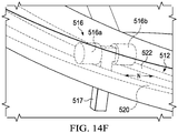
- Linkage 513 includes a roller track 512 fixedly mounted to door 204 and a roller mechanism 514 fixedly mounted to the nacelle 200.
- Roller track and roller mechanism 512, 514 are substantially similar in form and function to the roller track and door roller mechanism 214, except as noted herein.
- roller track 512 moves with door 204 as door 204 rotates into an open position 62, 64 and rides on roller mechanism 514.
- a forward portion 512f of the roller track 512 is mounted to an interior surface in the forward portion 204f of door 204 by conventional fasteners thereto (e.g., adhesives, screws, bolts).
- Roller track 512 can be rigidly connected to door 204 by intermediate supports 512s connecting the two, as shown in FIGS. 14A and 14D , or a web of intermediate supports 512s' between the door interior surface 204i and the track 512, as shown in FIG. 14E .
- the roller mechanism 514 rolls within the track 512 attached to the door 204 such that the forward hinges 208 move the proprotor housing 202 and drive the door 204 and track 512 through the fixed roller mechanism 514. This forces an orientation of the door 204 as it moves aft with the proprotor housing 202.
- the geometry of track 512 is defined to control the orientation of the door 204 for a desired aerodynamic profile and to avoid contact with adjacent structure as it moves.
- proprotor housing 202 rotates to a non-horizontal position 52, 54
- door 204 pivots at hinge fittings 208 and track 512 moves with door 204 being retained by the roller mechanism 514.
- track 512 can include a first and second tracks 520, 522 that define a channel N for receiving shaft 517 of roller mechanism 514.
- the end of aft portion 512a of the roller track 512 is connected to the roller mechanism 514 when door 204 is approaching or in a closed position, as shown in 14B.
- Roller mechanism 514 includes at least one roller 516 rotatably connected to a shaft 517, as shown in FIG. 14F .
- Roller 516 can include a first and second rollers 516a, 516b that the first and second tracks 520, 522 ride on during movement of door 204.
- a second set of rollers similar to the first and second rollers pair of rollers 516a, 516b can be disposed below rollers 516a, 516b to further constrain the path of the track and provide rigidity to the structure.
- rollers 516a, 516b can dampen vibrations from door 204.
- Shaft 517 can be mounted on the base 200s of the nacelle 200 using conventional fasteners (e.g., adhesives, screws, bolts).
- Linkage 613 can be a hinge member 650 that pivots in a pivot direction P as the proprotor housing 202 rotates.
- Hinge member 650 can include first and second hinge joints 652a, 652b each including a hinge pin 654 rigidly attached to and extend from proprotor housing 202.
- Hinge pin 654 is configured to engage with one or more bearings 656 attached to the inboard or outboard side 204i, 204o of the door 204.
- first and second hinge joints 652a, 652b are oriented to rotate about a rotation axis R to permit door 204 to pivot about hinge pins 654 when proprotor housing 202 is in a non-horizontal position.
- First and second hinge joints 652a, 652b can be disposed on outboard and inboard sides of door 204 to hingedly couple door 204 to proprotor housing 202.
- FIG. 15A is configured to allow pivoting movement of door 204 at hinge member 650 from about 0 degrees to 90 degrees relative to the longitudinal axis of the proprotor housing 202.
- the pivot movement of the hinge member 650 can permit the door 204 to rotate behind the proprotor housing 202 when in a non-horizontal position and retains the door 204 when the proprotor housing 202 is in a horizontal position.
- the door is generally in a 90 degrees orientation and the nacelle base portion 200s functions as a backstop that the aft end 204a rests thereon.
- the nacelle base portion 200s can include a reinforced portion for the load and/or sliding of the door 204 (e.g., a local rub strip of metal or Teflon) thereon and to limit wear on the nacelle base portion 200s.
- a reinforced portion for the load and/or sliding of the door 204 e.g., a local rub strip of metal or Teflon
- Linkage 613' can be a hinge member 650' that pivots in a pivot direction P as the proprotor housing 202 rotates.
- Hinge member 650' can include first and second hinge joints 652a', 652b' disposed on opposite ends of arm 652c'.
- First hinge joint 652a' can be adjacent to the forward portion of door 204 and is configured to be at least partially in a slot 202s in the proprotor housing 202 for moving therewith.
- Second hinge joint 652b' is coupled to the forward edge of the nacelle base portion 200s and adjacent to the aft portion of door 204.
- First and second hinge joints 652a', 652b' extend respectively from the proprotor housing 202 and the nacelle base portion 200s.
- Arm 652c' can be coupled to the interior surface 204i of the door 204 and is configured to impart movement from the first hinge joint 652a' to second hinge joint 652b' when proprotor rotates about rotation axis R.
- the linkage 613' causes door 204 to rotate generally vertically.
- the linkage 613' causes door 204 toward a horizontal position.
- linkage 613' is configured to allow pivoting movement of door 204 at hinge member 650' from about 0 degrees to 90 degrees relative to the longitudinal axis of the proprotor housing 202.
- the pivot movement of the hinge member 650' can permit the door 204 to rotate behind the proprotor housing 202 when in a non-horizontal position and retains the door 204 when the proprotor housing 202 is in a horizontal position.
- the door 204 is generally in a 90 degrees orientation.
- Linkages 613, 613' are exemplary embodiments of hinge members that can be used to move door 204 when the proprotor housing 202 is in a non-horizontal position. It should be appreciated that linkages 613, 613' may take on a wide variety of hinge configurations and the hinges can be located at various positions on the proprotor housing 202 and/or nacelle 200. Linkage 613, 613' can advantageously provide a mechanical connection that can prevent or minimize mechanical seizure (e.g., binding).
- door 704 includes a flexure portion 704m, 704n.
- a forward portion 704f of door 704 is fixedly connected to the aft portion 202a of proprotor housing 202 and an aft portion 704a of door 704 is fixedly connected to the base portion 200s of the nacelle 200.
- the flexure portions 704m, 704n bend and can permit the door 704 to fold on itself in response to rotation of the proprotor housing 202 in a non-horizontal orientation 50, 52.
- Flexure portions 704m, 704n extend and are generally oriented horizontally, straight, and/or planar when proprotor housing 200 is a horizontal orientation 50, 52.
- Flexure portions 704m, 704n can be disposed in the forward and aft portions 704f, 704a of the door 704. It is contemplated that there can be more or less flexure portions 704m, 704n (e.g., one, three, four, five, six, seven, eight, nine, or more flexure portions 704m, 704n) that can be oriented in various configurations to permit folding of door 704 during rotation of proprotor housing 202 in a non-horizontal position. In an embodiment, the flexure portions 704m, 704n can permit rolling of the door 704 onto a spindle associated with the proprotor housing 202 and/or the nacelle 200 to collect excess material.
- At least one flexure portion 704m, 704n can be a composite material.
- the composite material can be comprised of a matrix material and a reinforcement material.
- the reinforcement material can comprise a plurality of reinforcement layers configured to provide flexibility to the door 704 such that at least part of the composite material may fold, bend, or roll in response to rotation of the proprotor housing 202.
- the entire door 704 is comprised of a composite material that can include flexure portions 704m. 704n.
- At least one flexure portion 704m, 704n can be a fabric, textile, and/or an e-textile.
- the e-textile can be a smart fabric that is a fabric with digital components and electronics embedded therein to adjust a property of the fabric.
- the e-textile can be configured to permit flexure portions 704m, 704n to bend when proprotor housing 202 is in a non-horizontal position. Also shrinkage of the e-textile is possible to keep the material taunt for maximum aerodynamic and sealing benefit.
- door 704 is comprised entirely of a fabric, textile, and/or e-textile.
- flexure portion 704m, 704n is a rigid material that is configured to be folded onto itself.
- flexure portions 704m, 704n can include a hinge joint.
- the hinge joint can include a plurality of hinges along the flexure portion 704m extending from the outboard and inboard sides 704o, 704i of the door 704.
- door 704 is made from a rigid composite or metallic material including the flexure portions 704m, 704n.
- the plurality of doors 804 includes a first door 870 and a second door 872 disposed on the outboard and inboard sides of the nacelle 200, respectively.
- Each of first and second doors 870, 872 can be folded in to a closed position with first and second doors 870, 872 forming an aerodynamic shape when the proprotor housing 202 is in a horizontal position 50, as shown in FIG. 3A .
- first and second doors 870, 872 pivots open at hinge joints 808, as shown in FIG. 17A .
- each of first and second doors 870, 872 can be associated with an actuator 874, 876.
- Each of the actuators 874, 876 is configured to open and close first and second doors 870, 872, respectively, when the proprotor housing 202 is in a non-horizontal position.
- each actuator 874, 876 can be a linear actuator, a rotary actuator, or still another type of actuator that may be powered hydraulically, electrically, or still otherwise powered.
- each of the actuator mechanisms 874, 876 can be linked to the PRGB gearbox 125. The PRGB gearbox 125 can mechanically drive the actuators 874, 876.
- first and second doors 870, 872 can be ganged together by an interconnect shaft 877 to provide for even opening and closing.
- interconnect shaft 877 can be coupled to an actuator 878, which can rotate interconnect shaft 877 to open and close the first and second doors 870, 872.
- Actuator 877 can be a linear actuator, a rotary actuator, or still another type of actuator that may be powered hydraulically, electrically, or still otherwise powered.
- actuator 878 can be a hydraulic cylinder disposed in the middle of the first and second doors 870, 872 that can open and close the doors 870, 872 through a toggle linkage.
- first and second doors 870, 872 are configured to open and close with the proprotor housing 202 or PRGB gearbox 125 with a sliding door linkage 813'.
- first and second doors are mechanically connected via the door linkage 813' to the proprotor housing 202 or gearbox 125 such that first and second doors 870, 872 flip open when the proprotor housing 202 is in a non-horizontal orientation 52, 54 and flip closed when in a horizontal orientation 50.
- door linkage 813' includes a first sliding member 874' and a second sliding member 876'.
- first and second sliding members 874', 876' are associated with the first and second doors 870, 872, respectively (e.g., first and second sliding members 874', 876' can be movably connected to the interior surface of the first and second doors 870, 872). At least one of or both of the first and second sliding members 874', 876' are movably connected to the proprotor housing 202 or PRGB gearbox 125 such that as the proprotor housing 202 moves in a non-horizontal orientation, first and second sliding members 874', 876' move at least partially away or toward each other; thus, opening and closing the first and second doors 870, 872 therewith.
- sliding door linkage 813" can include a first pinned linkage 874" and a second pinned linkage 876" each associated with a slot 870s, 872s in the first and second doors 870, 872, respectively.
- each of the pinned linkages 874", 876" slide with the PRGB gearbox 125 in the respective slot 870s, 872s to allow sliding of the first and second doors 870, 782 as the proprotor housing 202 pivots from horizontal orientation 50 to non-horizontal orientations 52, 54.
- Door linkage 813" can advantageously provide a close connection between proprotor housing 202 and first and second doors 870, 872 and can prevent or minimize mechanical seizure (e.g., binding).
- a wide variety of a plurality of doors 804 and passive and active mechanisms for opening and closing the plurality of doors 804 may be utilized; for example, and not limitation, similar to bomb bay doors and mechanisms including a hydraulic cylinder disposed in the middle of the first and second doors 870, 872 that toggles the doors open and closed.
- Proprotor 973 for a propulsion system 111 is illustrated.
- Proprotor 973 is similar in form and function to the proprotor housing 202, except as noted herein.
- Proprotor 973 can be coupled to a nacelle 200.
- Proprotor 973 can include a forward portion 974 and an aft portion 976.
- the forward portion 974 includes a plurality of rotor blades 119 and gearbox 125.
- Forward portion 974 is configured to selectively pivot between a horizontal orientation and a non-horizontal orientation about a conversion axis C, as shown in FIGS. 18A-18B .
- the aft portion 976 When the forward portion 974 is in a non-horizontal orientation 952, 954, the aft portion 976 is in a horizonal orientation.
- the conversion axis C is disposed in the forward portion 974 of the proprotor 973.
- the forward portion 974 When the forward portion 974 is in a horizontal orientation 950, the aft portion 976 is in a horizontal orientation.
- Proprotor 973 can be disposed on an outboard end of a wing member 980.
- Wing member 980 includes a first rib 982 and a second rib 984.
- first rib 982 is the most outboard rib of the wing member 980.
- Wing member includes a forward spar 985, an aft spar 986, and a cove spar 987.
- An interconnect drive shaft 988 is disposed between the forward spar 985 and aft spar 986.
- the interconnect drive shaft 988 provides a torque path that enables a single engine to provide torque to both proprotors 111 and 113 in the event of a failure of the other engine.
- the second portion 976 is rigidly attached to the aft spar 986 and cove spar 987 and remains in horizontal position while the forward portion 974 can be in horizontal 950 and non-horizontal orientations 952, 954.
- a pivot mechanism 990 pivots the forward portion 974 between horizontal and non-horizontal orientations 950, 952, 954.
- the pivot mechanism 990 includes a cantilevered spindle 992 and an actuator 994.
- the cantilevered spindle is disposed between first rib 982 and second rib 984 and the actuator 994 can be a rotary actuator disposed outboard of first rib 982.
- Bearings 996 can be associated with the first and second ribs 982 to support the cantilevered spindle 992.
- the rotary actuator 994 engages the spindle 992.
- pivot mechanism may take on a wide variety of configurations.
- the forward portion 974 could be mechanically driven by a linear actuator in the outboard end of wing 980.
- proprotor 973 can be coupled to a nacelle 200.
- the aft portion 976 of proprotor 973 is a stationary aerodynamic fairing.
- the aft portion 976 encloses and supports an engine 123.
- proprotor 973 can have a length that is longer than conventional proprotors, e.g., proprotor housing 202.
- the illustrative embodiments described herein can advantageously provide a door that covers a recess aft of the proprotor or other aerodynamic configuration during forward flight (horizontal orientation) to reduce drag while maintaining structural integrity and stiffness.
- the term “couple” and its derivatives refer to any direct or indirect communication between two or more elements, whether or not those elements are in physical contact with one another.
- the term “or” is inclusive, meaning and/or.
- the phrases “associated with” and “associated therewith,” as well as derivatives thereof, may mean to include, be included within, interconnect with, contain, be contained within, connect to or with, couple to or with, be communicable with, cooperate with, interleave, juxtapose, be proximate to, be bound to or with, have, have a property of, or the like.
- the term “proprotor housing” refers to the exterior housing and can refer to internal components (e.g., gearbox 125 and other components) within the proprotor housing 202.
Priority Applications (2)
| Application Number | Priority Date | Filing Date | Title |
|---|---|---|---|
| EP19192072.7A EP3626612B1 (de) | 2017-03-02 | 2017-10-23 | Rotierende proprotorbaugruppe für kipprotorflugzeug |
| EP21155844.0A EP3901035B1 (de) | 2017-03-02 | 2017-10-23 | Rotierende proprotorbaugruppe für kipprotorflugzeug |
Applications Claiming Priority (3)
| Application Number | Priority Date | Filing Date | Title |
|---|---|---|---|
| US15/448,415 US10533603B2 (en) | 2017-03-02 | 2017-03-02 | Roller track assembly for a tiltrotor proprotor door |
| US15/448,136 US10539180B2 (en) | 2017-03-02 | 2017-03-02 | Bogie mechanism for a tiltrotor proprotor door |
| US15/661,129 US11046446B2 (en) | 2017-03-02 | 2017-07-27 | Tiltrotor aircraft rotating proprotor assembly |
Related Child Applications (3)
| Application Number | Title | Priority Date | Filing Date |
|---|---|---|---|
| EP19192072.7A Division EP3626612B1 (de) | 2017-03-02 | 2017-10-23 | Rotierende proprotorbaugruppe für kipprotorflugzeug |
| EP19192072.7A Division-Into EP3626612B1 (de) | 2017-03-02 | 2017-10-23 | Rotierende proprotorbaugruppe für kipprotorflugzeug |
| EP21155844.0A Division EP3901035B1 (de) | 2017-03-02 | 2017-10-23 | Rotierende proprotorbaugruppe für kipprotorflugzeug |
Publications (2)
| Publication Number | Publication Date |
|---|---|
| EP3369654A1 true EP3369654A1 (de) | 2018-09-05 |
| EP3369654B1 EP3369654B1 (de) | 2019-10-09 |
Family
ID=60162059
Family Applications (3)
| Application Number | Title | Priority Date | Filing Date |
|---|---|---|---|
| EP17197811.7A Active EP3369654B1 (de) | 2017-03-02 | 2017-10-23 | Rotierende proprotorbaugruppe für kipprotorflugzeug |
| EP21155844.0A Active EP3901035B1 (de) | 2017-03-02 | 2017-10-23 | Rotierende proprotorbaugruppe für kipprotorflugzeug |
| EP19192072.7A Active EP3626612B1 (de) | 2017-03-02 | 2017-10-23 | Rotierende proprotorbaugruppe für kipprotorflugzeug |
Family Applications After (2)
| Application Number | Title | Priority Date | Filing Date |
|---|---|---|---|
| EP21155844.0A Active EP3901035B1 (de) | 2017-03-02 | 2017-10-23 | Rotierende proprotorbaugruppe für kipprotorflugzeug |
| EP19192072.7A Active EP3626612B1 (de) | 2017-03-02 | 2017-10-23 | Rotierende proprotorbaugruppe für kipprotorflugzeug |
Country Status (3)
| Country | Link |
|---|---|
| US (1) | US11046446B2 (de) |
| EP (3) | EP3369654B1 (de) |
| CA (2) | CA2986741C (de) |
Cited By (6)
| Publication number | Priority date | Publication date | Assignee | Title |
|---|---|---|---|---|
| EP3549861A1 (de) * | 2018-04-05 | 2019-10-09 | Bell Helicopter Textron Inc. | Tor für einen kipprotor-proprotor-pylon |
| US10533603B2 (en) | 2017-03-02 | 2020-01-14 | Bell Helicopter Textron Inc. | Roller track assembly for a tiltrotor proprotor door |
| US10539180B2 (en) | 2017-03-02 | 2020-01-21 | Bell Helicopter Textron Inc. | Bogie mechanism for a tiltrotor proprotor door |
| US10875627B2 (en) | 2018-05-01 | 2020-12-29 | Bell Helicopter Textron Inc. | Movable cover for a proprotor nacelle |
| US10994853B2 (en) | 2017-03-02 | 2021-05-04 | Bell Helicopter Textron Inc. | Tiltrotor aircraft rotating proprotor assembly |
| US11046446B2 (en) | 2017-03-02 | 2021-06-29 | Bell Helicopter Textron Inc. | Tiltrotor aircraft rotating proprotor assembly |
Families Citing this family (7)
| Publication number | Priority date | Publication date | Assignee | Title |
|---|---|---|---|---|
| US10513332B2 (en) * | 2015-10-05 | 2019-12-24 | Sikorsky Aircraft Corporation | Tiltwing aircraft |
| US11136941B2 (en) * | 2017-11-09 | 2021-10-05 | Abe Karem | Devices and methods for exhaust vectoring in tilt rotor aircraft |
| US11148798B2 (en) * | 2018-06-22 | 2021-10-19 | Textron Innovations Inc. | Engine and rotatable proprotor configurations for a tiltrotor aircraft |
| US10913542B2 (en) * | 2018-07-27 | 2021-02-09 | Textron Innovations Inc. | Conversion actuator and downstop striker fitting for a tiltrotor aircraft |
| US10994839B2 (en) | 2018-07-31 | 2021-05-04 | Textron Innovations Inc. | System and method for rotating a rotor of a tiltrotor aircraft |
| CN113320694B (zh) * | 2021-07-13 | 2023-08-18 | 广东汇天航空航天科技有限公司 | 倾转旋翼机构及具有倾转旋翼机构的飞行器 |
| US11679872B1 (en) | 2022-12-12 | 2023-06-20 | Archer Aviation Inc. | Tilter motor cooling apparatus for vertical takeoff and landing aircraft and operating method of the same |
Citations (7)
| Publication number | Priority date | Publication date | Assignee | Title |
|---|---|---|---|---|
| US3666209A (en) * | 1970-02-24 | 1972-05-30 | Boeing Co | V/stol aircraft with variable tilt wing |
| US4037809A (en) * | 1974-11-13 | 1977-07-26 | Societe Nationale D'etude Et De Construction De Moteurs D'aviation | Device for mounting a turboreactor on an aeroplane |
| US6260793B1 (en) * | 1999-03-30 | 2001-07-17 | Eurocopter | Convertible aircraft with tilting rotors |
| US6382556B1 (en) * | 1999-12-20 | 2002-05-07 | Roger N. C. Pham | VTOL airplane with only one tiltable prop-rotor |
| US20050045762A1 (en) * | 2003-01-09 | 2005-03-03 | Pham Roger N. | High performance VTOL convertiplanes |
| US9126678B2 (en) * | 2013-03-13 | 2015-09-08 | Bell Helicopter Textron Inc. | Spindle mounted tiltrotor pylon with fixed engine arrangement |
| US9174731B2 (en) | 2013-08-14 | 2015-11-03 | Bell Helicopter Textron Inc. | Fixed engine and rotating proprotor arrangement for a tiltrotor aircraft |
Family Cites Families (26)
| Publication number | Priority date | Publication date | Assignee | Title |
|---|---|---|---|---|
| CA609752A (en) | 1957-12-02 | 1960-11-29 | General Electric Company | Electric power take-off device |
| US3392244A (en) | 1965-07-26 | 1968-07-09 | Vahle Paul Kg | Safety trolley duct and carriage for same |
| FR2373427A1 (fr) | 1976-12-10 | 1978-07-07 | Monne Maxime | Perfectionnements apportes aux monorails et convoyeurs |
| US5395073A (en) * | 1992-03-13 | 1995-03-07 | Freewing Aerial Robotics Corporation | STOL/VTOL free wing aircraft with articulated tail boom |
| US5863013A (en) * | 1991-11-20 | 1999-01-26 | Freewing Aerial Robotics Corporation | STOL/VTOL free wing aircraft with improved shock dampening and absorbing means |
| DE19746208C2 (de) | 1997-10-20 | 2000-04-06 | Dorma Gmbh & Co Kg | Laufschiene für ein Laufwerk für eine hängend gelagerte Trennwand |
| US6598355B2 (en) | 2000-04-04 | 2003-07-29 | Modernfold, Inc. | Anti-stacking system for operable walls |
| GB2376928B (en) | 2001-05-16 | 2003-04-30 | John Frederick Austen-Brown | Personal hoverplane having four tiltmotors |
| US7143973B2 (en) * | 2003-11-14 | 2006-12-05 | Kenneth Sye Ballew | Avia tilting-rotor convertiplane |
| FR2874051B1 (fr) | 2004-08-05 | 2006-09-08 | Andre Prieur | Arret de porte a positions de maintien indeterminees |
| FR2892142B1 (fr) | 2005-10-19 | 2008-02-01 | Peugeot Citroen Automobiles Sa | Dispositif de guidage pour porte coulissante d'un vehicule automobile et porte coulissante d'un tel dispositif de guidage. |
| PL2041385T3 (pl) | 2006-07-14 | 2020-03-31 | Ceta Elektromechanik Gmbh | Urządzenie dla bram przesuwnych lub drzwi przesuwnych |
| US8066219B2 (en) * | 2008-04-25 | 2011-11-29 | Karem Aircraft, Inc. | Anhedral tip blades for tiltrotor aircraft |
| FR2933956B1 (fr) * | 2008-07-18 | 2010-07-30 | Airbus France | Dispositif pour ceinturer une nacelle d'aeronef |
| JP5135110B2 (ja) | 2008-08-01 | 2013-01-30 | ホンダ・パテンツ・アンド・テクノロジーズ・ノース・アメリカ・エルエルシー | 航空機のスライドドア装置 |
| US8308221B2 (en) | 2009-10-20 | 2012-11-13 | Honda Motor Co., Ltd. | Roller assembly for sliding vehicle closure |
| US8602347B2 (en) | 2011-02-04 | 2013-12-10 | Textron Innovations Inc. | Tilt rotor aircraft with fixed engine arrangement |
| DE202011003758U1 (de) | 2011-03-10 | 2012-06-14 | Hüppe GmbH | Duschabtrennung sowie Duschkabine mit Bremsmechanismus |
| JP6393190B2 (ja) | 2012-03-15 | 2018-09-19 | ランダ コーポレイション リミテッド | 印刷システムのためのエンドレスフレキシブルベルト |
| US10106255B2 (en) * | 2014-05-14 | 2018-10-23 | Bell Helicopter Textron Inc. | Rotary pylon conversion actuator for tiltrotor aircraft |
| IL233902B (en) * | 2014-07-31 | 2020-07-30 | Israel Aerospace Ind Ltd | egnition system |
| US10994853B2 (en) | 2017-03-02 | 2021-05-04 | Bell Helicopter Textron Inc. | Tiltrotor aircraft rotating proprotor assembly |
| US10533603B2 (en) | 2017-03-02 | 2020-01-14 | Bell Helicopter Textron Inc. | Roller track assembly for a tiltrotor proprotor door |
| US10539180B2 (en) | 2017-03-02 | 2020-01-21 | Bell Helicopter Textron Inc. | Bogie mechanism for a tiltrotor proprotor door |
| US11046446B2 (en) | 2017-03-02 | 2021-06-29 | Bell Helicopter Textron Inc. | Tiltrotor aircraft rotating proprotor assembly |
| US10875627B2 (en) | 2018-05-01 | 2020-12-29 | Bell Helicopter Textron Inc. | Movable cover for a proprotor nacelle |
-
2017
- 2017-07-27 US US15/661,129 patent/US11046446B2/en active Active
- 2017-10-23 EP EP17197811.7A patent/EP3369654B1/de active Active
- 2017-10-23 EP EP21155844.0A patent/EP3901035B1/de active Active
- 2017-10-23 EP EP19192072.7A patent/EP3626612B1/de active Active
- 2017-11-23 CA CA2986741A patent/CA2986741C/en active Active
- 2017-11-23 CA CA3087390A patent/CA3087390C/en active Active
Patent Citations (7)
| Publication number | Priority date | Publication date | Assignee | Title |
|---|---|---|---|---|
| US3666209A (en) * | 1970-02-24 | 1972-05-30 | Boeing Co | V/stol aircraft with variable tilt wing |
| US4037809A (en) * | 1974-11-13 | 1977-07-26 | Societe Nationale D'etude Et De Construction De Moteurs D'aviation | Device for mounting a turboreactor on an aeroplane |
| US6260793B1 (en) * | 1999-03-30 | 2001-07-17 | Eurocopter | Convertible aircraft with tilting rotors |
| US6382556B1 (en) * | 1999-12-20 | 2002-05-07 | Roger N. C. Pham | VTOL airplane with only one tiltable prop-rotor |
| US20050045762A1 (en) * | 2003-01-09 | 2005-03-03 | Pham Roger N. | High performance VTOL convertiplanes |
| US9126678B2 (en) * | 2013-03-13 | 2015-09-08 | Bell Helicopter Textron Inc. | Spindle mounted tiltrotor pylon with fixed engine arrangement |
| US9174731B2 (en) | 2013-08-14 | 2015-11-03 | Bell Helicopter Textron Inc. | Fixed engine and rotating proprotor arrangement for a tiltrotor aircraft |
Cited By (7)
| Publication number | Priority date | Publication date | Assignee | Title |
|---|---|---|---|---|
| US10533603B2 (en) | 2017-03-02 | 2020-01-14 | Bell Helicopter Textron Inc. | Roller track assembly for a tiltrotor proprotor door |
| US10539180B2 (en) | 2017-03-02 | 2020-01-21 | Bell Helicopter Textron Inc. | Bogie mechanism for a tiltrotor proprotor door |
| US10994853B2 (en) | 2017-03-02 | 2021-05-04 | Bell Helicopter Textron Inc. | Tiltrotor aircraft rotating proprotor assembly |
| US11046446B2 (en) | 2017-03-02 | 2021-06-29 | Bell Helicopter Textron Inc. | Tiltrotor aircraft rotating proprotor assembly |
| EP3549861A1 (de) * | 2018-04-05 | 2019-10-09 | Bell Helicopter Textron Inc. | Tor für einen kipprotor-proprotor-pylon |
| US10994852B2 (en) | 2018-04-05 | 2021-05-04 | Bell Helicopter Textron Inc. | Door for a tiltrotor proprotor pylon |
| US10875627B2 (en) | 2018-05-01 | 2020-12-29 | Bell Helicopter Textron Inc. | Movable cover for a proprotor nacelle |
Also Published As
| Publication number | Publication date |
|---|---|
| CA2986741C (en) | 2020-09-29 |
| CA3087390C (en) | 2022-08-09 |
| EP3626612B1 (de) | 2021-08-25 |
| EP3901035B1 (de) | 2023-04-05 |
| EP3626612A1 (de) | 2020-03-25 |
| CA3087390A1 (en) | 2018-09-02 |
| US20180251227A1 (en) | 2018-09-06 |
| EP3369654B1 (de) | 2019-10-09 |
| CA2986741A1 (en) | 2018-09-02 |
| EP3901035A1 (de) | 2021-10-27 |
| US11046446B2 (en) | 2021-06-29 |
Similar Documents
| Publication | Publication Date | Title |
|---|---|---|
| CA2986741C (en) | Tiltrotor aircraft rotating proprotor assembly | |
| US11492131B2 (en) | Tiltrotor aircraft rotating proprotor assembly | |
| EP3378767B1 (de) | Rollenbahnanordnung für eine kipprotor-proprotortür | |
| EP3369659B1 (de) | Drehgestellmechanismus für eine proprotortür eines kipprotorflugzeugs | |
| CA3033754C (en) | Auxiliary support system for a flap of an aircraft wing | |
| US8763953B2 (en) | Aircraft flap actuator assembly | |
| US5337974A (en) | Wing pivot structure | |
| EP3134314B1 (de) | Flugzeug mit einer faltbaren flügelspitzenvorrichtung | |
| EP2148813B1 (de) | Luftfahrzeug | |
| US20060016927A1 (en) | Method and apparatus for rotatably supporting movable components, including canards | |
| US8777151B2 (en) | Method for connecting a tension-torsion strap | |
| CN110294098B (zh) | 用于可折叠飞机机翼的铰链销 | |
| US5110072A (en) | Control surface stabilizer hinge | |
| US10807694B2 (en) | Track integrated with rails, outer mold line, and support for step loads | |
| EP3456629B1 (de) | Offenhalte- und verriegelungsmechanismus mit j-förmiger schiene für eine verkleidung eines flugzeugs | |
| EP3868990B1 (de) | Selbstausrichtendes türdrehgestell | |
| US20230348040A1 (en) | Hinge mechanisms for coupling flight control members to aircraft components and associated methods | |
| GB2612317A (en) | Moveable wing tip arrangements |
Legal Events
| Date | Code | Title | Description |
|---|---|---|---|
| STAA | Information on the status of an ep patent application or granted ep patent |
Free format text: STATUS: EXAMINATION IS IN PROGRESS |
|
| PUAI | Public reference made under article 153(3) epc to a published international application that has entered the european phase |
Free format text: ORIGINAL CODE: 0009012 |
|
| 17P | Request for examination filed |
Effective date: 20171023 |
|
| AK | Designated contracting states |
Kind code of ref document: A1 Designated state(s): AL AT BE BG CH CY CZ DE DK EE ES FI FR GB GR HR HU IE IS IT LI LT LU LV MC MK MT NL NO PL PT RO RS SE SI SK SM TR |
|
| AX | Request for extension of the european patent |
Extension state: BA ME |
|
| GRAP | Despatch of communication of intention to grant a patent |
Free format text: ORIGINAL CODE: EPIDOSNIGR1 |
|
| STAA | Information on the status of an ep patent application or granted ep patent |
Free format text: STATUS: GRANT OF PATENT IS INTENDED |
|
| RIC1 | Information provided on ipc code assigned before grant |
Ipc: B64C 7/02 20060101ALI20190425BHEP Ipc: B64D 29/06 20060101ALN20190425BHEP Ipc: B64C 29/00 20060101AFI20190425BHEP |
|
| RIC1 | Information provided on ipc code assigned before grant |
Ipc: B64D 29/06 20060101ALN20190507BHEP Ipc: B64C 29/00 20060101AFI20190507BHEP Ipc: B64C 7/02 20060101ALI20190507BHEP |
|
| INTG | Intention to grant announced |
Effective date: 20190523 |
|
| GRAS | Grant fee paid |
Free format text: ORIGINAL CODE: EPIDOSNIGR3 |
|
| GRAA | (expected) grant |
Free format text: ORIGINAL CODE: 0009210 |
|
| STAA | Information on the status of an ep patent application or granted ep patent |
Free format text: STATUS: THE PATENT HAS BEEN GRANTED |
|
| AK | Designated contracting states |
Kind code of ref document: B1 Designated state(s): AL AT BE BG CH CY CZ DE DK EE ES FI FR GB GR HR HU IE IS IT LI LT LU LV MC MK MT NL NO PL PT RO RS SE SI SK SM TR |
|
| REG | Reference to a national code |
Ref country code: GB Ref legal event code: FG4D |
|
| REG | Reference to a national code |
Ref country code: CH Ref legal event code: EP |
|
| REG | Reference to a national code |
Ref country code: IE Ref legal event code: FG4D |
|
| REG | Reference to a national code |
Ref country code: DE Ref legal event code: R096 Ref document number: 602017007642 Country of ref document: DE |
|
| REG | Reference to a national code |
Ref country code: AT Ref legal event code: REF Ref document number: 1188504 Country of ref document: AT Kind code of ref document: T Effective date: 20191115 |
|
| REG | Reference to a national code |
Ref country code: NL Ref legal event code: MP Effective date: 20191009 |
|
| REG | Reference to a national code |
Ref country code: LT Ref legal event code: MG4D |
|
| REG | Reference to a national code |
Ref country code: AT Ref legal event code: MK05 Ref document number: 1188504 Country of ref document: AT Kind code of ref document: T Effective date: 20191009 |
|
| PG25 | Lapsed in a contracting state [announced via postgrant information from national office to epo] |
Ref country code: GR Free format text: LAPSE BECAUSE OF FAILURE TO SUBMIT A TRANSLATION OF THE DESCRIPTION OR TO PAY THE FEE WITHIN THE PRESCRIBED TIME-LIMIT Effective date: 20200110 Ref country code: FI Free format text: LAPSE BECAUSE OF FAILURE TO SUBMIT A TRANSLATION OF THE DESCRIPTION OR TO PAY THE FEE WITHIN THE PRESCRIBED TIME-LIMIT Effective date: 20191009 Ref country code: PT Free format text: LAPSE BECAUSE OF FAILURE TO SUBMIT A TRANSLATION OF THE DESCRIPTION OR TO PAY THE FEE WITHIN THE PRESCRIBED TIME-LIMIT Effective date: 20200210 Ref country code: NL Free format text: LAPSE BECAUSE OF FAILURE TO SUBMIT A TRANSLATION OF THE DESCRIPTION OR TO PAY THE FEE WITHIN THE PRESCRIBED TIME-LIMIT Effective date: 20191009 Ref country code: SE Free format text: LAPSE BECAUSE OF FAILURE TO SUBMIT A TRANSLATION OF THE DESCRIPTION OR TO PAY THE FEE WITHIN THE PRESCRIBED TIME-LIMIT Effective date: 20191009 Ref country code: LV Free format text: LAPSE BECAUSE OF FAILURE TO SUBMIT A TRANSLATION OF THE DESCRIPTION OR TO PAY THE FEE WITHIN THE PRESCRIBED TIME-LIMIT Effective date: 20191009 Ref country code: AT Free format text: LAPSE BECAUSE OF FAILURE TO SUBMIT A TRANSLATION OF THE DESCRIPTION OR TO PAY THE FEE WITHIN THE PRESCRIBED TIME-LIMIT Effective date: 20191009 Ref country code: LT Free format text: LAPSE BECAUSE OF FAILURE TO SUBMIT A TRANSLATION OF THE DESCRIPTION OR TO PAY THE FEE WITHIN THE PRESCRIBED TIME-LIMIT Effective date: 20191009 Ref country code: ES Free format text: LAPSE BECAUSE OF FAILURE TO SUBMIT A TRANSLATION OF THE DESCRIPTION OR TO PAY THE FEE WITHIN THE PRESCRIBED TIME-LIMIT Effective date: 20191009 Ref country code: NO Free format text: LAPSE BECAUSE OF FAILURE TO SUBMIT A TRANSLATION OF THE DESCRIPTION OR TO PAY THE FEE WITHIN THE PRESCRIBED TIME-LIMIT Effective date: 20200109 Ref country code: BG Free format text: LAPSE BECAUSE OF FAILURE TO SUBMIT A TRANSLATION OF THE DESCRIPTION OR TO PAY THE FEE WITHIN THE PRESCRIBED TIME-LIMIT Effective date: 20200109 Ref country code: PL Free format text: LAPSE BECAUSE OF FAILURE TO SUBMIT A TRANSLATION OF THE DESCRIPTION OR TO PAY THE FEE WITHIN THE PRESCRIBED TIME-LIMIT Effective date: 20191009 |
|
| PG25 | Lapsed in a contracting state [announced via postgrant information from national office to epo] |
Ref country code: RS Free format text: LAPSE BECAUSE OF FAILURE TO SUBMIT A TRANSLATION OF THE DESCRIPTION OR TO PAY THE FEE WITHIN THE PRESCRIBED TIME-LIMIT Effective date: 20191009 Ref country code: HR Free format text: LAPSE BECAUSE OF FAILURE TO SUBMIT A TRANSLATION OF THE DESCRIPTION OR TO PAY THE FEE WITHIN THE PRESCRIBED TIME-LIMIT Effective date: 20191009 Ref country code: IS Free format text: LAPSE BECAUSE OF FAILURE TO SUBMIT A TRANSLATION OF THE DESCRIPTION OR TO PAY THE FEE WITHIN THE PRESCRIBED TIME-LIMIT Effective date: 20200224 |
|
| PG25 | Lapsed in a contracting state [announced via postgrant information from national office to epo] |
Ref country code: AL Free format text: LAPSE BECAUSE OF FAILURE TO SUBMIT A TRANSLATION OF THE DESCRIPTION OR TO PAY THE FEE WITHIN THE PRESCRIBED TIME-LIMIT Effective date: 20191009 |
|
| REG | Reference to a national code |
Ref country code: DE Ref legal event code: R097 Ref document number: 602017007642 Country of ref document: DE |
|
| PG2D | Information on lapse in contracting state deleted |
Ref country code: IS |
|
| PG25 | Lapsed in a contracting state [announced via postgrant information from national office to epo] |
Ref country code: DK Free format text: LAPSE BECAUSE OF FAILURE TO SUBMIT A TRANSLATION OF THE DESCRIPTION OR TO PAY THE FEE WITHIN THE PRESCRIBED TIME-LIMIT Effective date: 20191009 Ref country code: MC Free format text: LAPSE BECAUSE OF FAILURE TO SUBMIT A TRANSLATION OF THE DESCRIPTION OR TO PAY THE FEE WITHIN THE PRESCRIBED TIME-LIMIT Effective date: 20191009 Ref country code: LU Free format text: LAPSE BECAUSE OF NON-PAYMENT OF DUE FEES Effective date: 20191023 Ref country code: CZ Free format text: LAPSE BECAUSE OF FAILURE TO SUBMIT A TRANSLATION OF THE DESCRIPTION OR TO PAY THE FEE WITHIN THE PRESCRIBED TIME-LIMIT Effective date: 20191009 Ref country code: RO Free format text: LAPSE BECAUSE OF FAILURE TO SUBMIT A TRANSLATION OF THE DESCRIPTION OR TO PAY THE FEE WITHIN THE PRESCRIBED TIME-LIMIT Effective date: 20191009 Ref country code: EE Free format text: LAPSE BECAUSE OF FAILURE TO SUBMIT A TRANSLATION OF THE DESCRIPTION OR TO PAY THE FEE WITHIN THE PRESCRIBED TIME-LIMIT Effective date: 20191009 Ref country code: IS Free format text: LAPSE BECAUSE OF FAILURE TO SUBMIT A TRANSLATION OF THE DESCRIPTION OR TO PAY THE FEE WITHIN THE PRESCRIBED TIME-LIMIT Effective date: 20200209 |
|
| REG | Reference to a national code |
Ref country code: BE Ref legal event code: MM Effective date: 20191031 |
|
| PLBE | No opposition filed within time limit |
Free format text: ORIGINAL CODE: 0009261 |
|
| STAA | Information on the status of an ep patent application or granted ep patent |
Free format text: STATUS: NO OPPOSITION FILED WITHIN TIME LIMIT |
|
| PG25 | Lapsed in a contracting state [announced via postgrant information from national office to epo] |
Ref country code: BE Free format text: LAPSE BECAUSE OF NON-PAYMENT OF DUE FEES Effective date: 20191031 Ref country code: SK Free format text: LAPSE BECAUSE OF FAILURE TO SUBMIT A TRANSLATION OF THE DESCRIPTION OR TO PAY THE FEE WITHIN THE PRESCRIBED TIME-LIMIT Effective date: 20191009 Ref country code: SM Free format text: LAPSE BECAUSE OF FAILURE TO SUBMIT A TRANSLATION OF THE DESCRIPTION OR TO PAY THE FEE WITHIN THE PRESCRIBED TIME-LIMIT Effective date: 20191009 |
|
| 26N | No opposition filed |
Effective date: 20200710 |
|
| PG25 | Lapsed in a contracting state [announced via postgrant information from national office to epo] |
Ref country code: IE Free format text: LAPSE BECAUSE OF NON-PAYMENT OF DUE FEES Effective date: 20191023 |
|
| PG25 | Lapsed in a contracting state [announced via postgrant information from national office to epo] |
Ref country code: SI Free format text: LAPSE BECAUSE OF FAILURE TO SUBMIT A TRANSLATION OF THE DESCRIPTION OR TO PAY THE FEE WITHIN THE PRESCRIBED TIME-LIMIT Effective date: 20191009 |
|
| PG25 | Lapsed in a contracting state [announced via postgrant information from national office to epo] |
Ref country code: CY Free format text: LAPSE BECAUSE OF FAILURE TO SUBMIT A TRANSLATION OF THE DESCRIPTION OR TO PAY THE FEE WITHIN THE PRESCRIBED TIME-LIMIT Effective date: 20191009 |
|
| REG | Reference to a national code |
Ref country code: CH Ref legal event code: PL |
|
| PG25 | Lapsed in a contracting state [announced via postgrant information from national office to epo] |
Ref country code: CH Free format text: LAPSE BECAUSE OF FAILURE TO SUBMIT A TRANSLATION OF THE DESCRIPTION OR TO PAY THE FEE WITHIN THE PRESCRIBED TIME-LIMIT Effective date: 20201031 Ref country code: LI Free format text: LAPSE BECAUSE OF FAILURE TO SUBMIT A TRANSLATION OF THE DESCRIPTION OR TO PAY THE FEE WITHIN THE PRESCRIBED TIME-LIMIT Effective date: 20201031 |
|
| PG25 | Lapsed in a contracting state [announced via postgrant information from national office to epo] |
Ref country code: MT Free format text: LAPSE BECAUSE OF FAILURE TO SUBMIT A TRANSLATION OF THE DESCRIPTION OR TO PAY THE FEE WITHIN THE PRESCRIBED TIME-LIMIT Effective date: 20191009 Ref country code: HU Free format text: LAPSE BECAUSE OF FAILURE TO SUBMIT A TRANSLATION OF THE DESCRIPTION OR TO PAY THE FEE WITHIN THE PRESCRIBED TIME-LIMIT; INVALID AB INITIO Effective date: 20171023 |
|
| PG25 | Lapsed in a contracting state [announced via postgrant information from national office to epo] |
Ref country code: TR Free format text: LAPSE BECAUSE OF FAILURE TO SUBMIT A TRANSLATION OF THE DESCRIPTION OR TO PAY THE FEE WITHIN THE PRESCRIBED TIME-LIMIT Effective date: 20191009 |
|
| PG25 | Lapsed in a contracting state [announced via postgrant information from national office to epo] |
Ref country code: MK Free format text: LAPSE BECAUSE OF FAILURE TO SUBMIT A TRANSLATION OF THE DESCRIPTION OR TO PAY THE FEE WITHIN THE PRESCRIBED TIME-LIMIT Effective date: 20191009 |
|
| P01 | Opt-out of the competence of the unified patent court (upc) registered |
Effective date: 20230602 |
|
| PGFP | Annual fee paid to national office [announced via postgrant information from national office to epo] |
Ref country code: GB Payment date: 20231027 Year of fee payment: 7 |
|
| PGFP | Annual fee paid to national office [announced via postgrant information from national office to epo] |
Ref country code: IT Payment date: 20231023 Year of fee payment: 7 Ref country code: FR Payment date: 20231025 Year of fee payment: 7 Ref country code: DE Payment date: 20231027 Year of fee payment: 7 |