EP3369637B1 - Motrice de train à grande vitesse - Google Patents
Motrice de train à grande vitesse Download PDFInfo
- Publication number
- EP3369637B1 EP3369637B1 EP18159106.6A EP18159106A EP3369637B1 EP 3369637 B1 EP3369637 B1 EP 3369637B1 EP 18159106 A EP18159106 A EP 18159106A EP 3369637 B1 EP3369637 B1 EP 3369637B1
- Authority
- EP
- European Patent Office
- Prior art keywords
- zone
- power unit
- traction
- technical
- roof
- Prior art date
- Legal status (The legal status is an assumption and is not a legal conclusion. Google has not performed a legal analysis and makes no representation as to the accuracy of the status listed.)
- Active
Links
Images
Classifications
-
- B—PERFORMING OPERATIONS; TRANSPORTING
- B60—VEHICLES IN GENERAL
- B60L—PROPULSION OF ELECTRICALLY-PROPELLED VEHICLES; SUPPLYING ELECTRIC POWER FOR AUXILIARY EQUIPMENT OF ELECTRICALLY-PROPELLED VEHICLES; ELECTRODYNAMIC BRAKE SYSTEMS FOR VEHICLES IN GENERAL; MAGNETIC SUSPENSION OR LEVITATION FOR VEHICLES; MONITORING OPERATING VARIABLES OF ELECTRICALLY-PROPELLED VEHICLES; ELECTRIC SAFETY DEVICES FOR ELECTRICALLY-PROPELLED VEHICLES
- B60L5/00—Current collectors for power supply lines of electrically-propelled vehicles
-
- B—PERFORMING OPERATIONS; TRANSPORTING
- B61—RAILWAYS
- B61C—LOCOMOTIVES; MOTOR RAILCARS
- B61C17/00—Arrangement or disposition of parts; Details or accessories not otherwise provided for; Use of control gear and control systems
- B61C17/04—Arrangement or disposition of driving cabins, footplates or engine rooms; Ventilation thereof
-
- B—PERFORMING OPERATIONS; TRANSPORTING
- B61—RAILWAYS
- B61C—LOCOMOTIVES; MOTOR RAILCARS
- B61C17/00—Arrangement or disposition of parts; Details or accessories not otherwise provided for; Use of control gear and control systems
- B61C17/06—Power storing devices
-
- B—PERFORMING OPERATIONS; TRANSPORTING
- B61—RAILWAYS
- B61C—LOCOMOTIVES; MOTOR RAILCARS
- B61C3/00—Electric locomotives or railcars
-
- B—PERFORMING OPERATIONS; TRANSPORTING
- B61—RAILWAYS
- B61D—BODY DETAILS OR KINDS OF RAILWAY VEHICLES
- B61D1/00—Carriages for ordinary railway passenger traffic
-
- B—PERFORMING OPERATIONS; TRANSPORTING
- B61—RAILWAYS
- B61D—BODY DETAILS OR KINDS OF RAILWAY VEHICLES
- B61D27/00—Heating, cooling, ventilating, or air-conditioning
-
- B—PERFORMING OPERATIONS; TRANSPORTING
- B61—RAILWAYS
- B61D—BODY DETAILS OR KINDS OF RAILWAY VEHICLES
- B61D27/00—Heating, cooling, ventilating, or air-conditioning
- B61D27/0018—Air-conditioning means, i.e. combining at least two of the following ways of treating or supplying air, namely heating, cooling or ventilating
-
- B—PERFORMING OPERATIONS; TRANSPORTING
- B61—RAILWAYS
- B61D—BODY DETAILS OR KINDS OF RAILWAY VEHICLES
- B61D39/00—Wagon or like covers; Tarpaulins; Movable or foldable roofs
-
- Y—GENERAL TAGGING OF NEW TECHNOLOGICAL DEVELOPMENTS; GENERAL TAGGING OF CROSS-SECTIONAL TECHNOLOGIES SPANNING OVER SEVERAL SECTIONS OF THE IPC; TECHNICAL SUBJECTS COVERED BY FORMER USPC CROSS-REFERENCE ART COLLECTIONS [XRACs] AND DIGESTS
- Y02—TECHNOLOGIES OR APPLICATIONS FOR MITIGATION OR ADAPTATION AGAINST CLIMATE CHANGE
- Y02T—CLIMATE CHANGE MITIGATION TECHNOLOGIES RELATED TO TRANSPORTATION
- Y02T30/00—Transportation of goods or passengers via railways, e.g. energy recovery or reducing air resistance
Definitions
- the present invention relates to a high-speed train engine, in particular for transporting passengers.
- High-speed trains have recently experienced a remarkable development, attracting an increasing number of travelers.
- passenger transport is authorized only with a seat reservation, for proper compliance with safety standards. For this reason, the number of passengers allowed and the economic performance of the company that operates the transport service is linked to the size of the train itself, i.e. the number of seats available.
- a high-speed train has one or more power units, most often one at each end of the train set, and a number of passenger cars.
- the current architecture of a head engine of a high speed train includes traction units, a transformer and electrical cabinets installed in the central part of a machine compartment, with two side lanes 500 mm wide.
- the high voltage equipment is placed on the roof, while the braking equipment, the cabin air conditioning equipment and the batteries are installed below the body.
- the air intakes to cool this equipment are made by the side faces of the structure of the engine body.
- four hoods are normally provided on the roof, which allow maintenance of each part of the engine.
- CN203888794U describes an electric locomotive where a corridor is arranged in the center of a machine room lengthwise, while equipment is installed on both sides of this corridor.
- this locomotive is as long as those of the prior art.
- EP2314492 describes a two-mode railway train consisting of several vehicles, and a railway convoy formed of such trains having a low floor over the entire length of the train.
- WO2016 / 139167 describes a railway vehicle, a production method and a method for driving a railway vehicle which comprises at least one car body of known type.
- An object of the invention is therefore to provide a high-speed train engine which does not have the drawbacks of the architecture of the state of the art.
- the length of the motor can be reduced, while it accommodates all the functional components necessary for its operation.
- this power unit can incorporate one or more of the following characteristics, taken in any technically acceptable combination.
- the motor coach comprises electric power cables configured to be connected to electric energy storage batteries arranged in a railway car adjacent to the motor coach.
- the power unit comprises an electrical box comprising the main transformer and at least one additional winding, the electrical box being placed under the body between the bogies.
- the traction zone comprises at least one traction unit electrically connected to the additional winding, the traction unit and the additional winding forming an electrical energy conversion circuit.
- the traction zone and the technical zone each comprise a ventilation unit.
- the technical compartment comprises a central corridor having a width measured perpendicular to the longitudinal axis and in a horizontal direction in the normal configuration of use of this power unit which has a value between 500 and 750mm.
- the low voltage zone, the traction zone and the technical zone each comprise at least one air inlet and one air outlet respectively installed in height, in roofing.
- the technical area is located at a rear end of the motor opposite the anterior end where the driver's cabin and the low voltage area, the traction area and the technical area are located. being placed respectively one beside the other along the longitudinal axis of the motor.
- a pantograph is placed on the roof of the technical area and in which the technical area comprises, under a roof cover, a high voltage unit comprising a circuit breaker and / or a disconnect switch specific to electrically isolate the pantograph from a traction chain included in the motor.
- the power unit comprises three removable cowls installed on the roof to protect the equipment mounted on the roof at the low voltage, traction and technical zones respectively.
- a power unit according to the invention 1 comprises a body 2 having a roof 2a and a floor 2b and which has a front end 2c capable of accommodating a driver's cabin 4 visible through its windshield and one of its side windows.
- the front of the engine 1 is defined as the side towards which it advances in normal operation.
- the rear of the motor is opposite the front of the motor.
- an arrow S goes from the front to the rear of the motor 1.
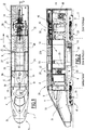
- a technical compartment 18 including a low voltage zone 6 where an HVAC system 8 is installed (Heat Ventilation Air conditioning and Cooling) suitable for air conditioning the driver's cab 4; a traction zone 17 described in detail below; and a technical zone 29 also described in detail below.
- HVAC system 8 Heating Ventilation Air conditioning and Cooling
- the HVAC system 8 of the engine 1 comprises two intake air intakes 8a and an air outlet 8b.
- the HVAC 8 system can be seen at figure 2 .
- the low-voltage zone is also equipped with an air outlet 8c for the internal air of the technical compartment 18.
- An inlet opening on each side of the motor which is normally closed by a door 9, opens into the technical compartment 18 at the low voltage zone 6.
- These systems known to those skilled in the art are integrated in control cabinets 11 arranged along 'a longitudinal axis X1 of the engine 1, between the driver's cab 4 and the doors 9.
- the traction zone 17 comprises two traction blocks 50 of the motor 1.
- the figure 2 shows the rheostatic brake 22 with its ventilation unit 22b.
- the HVAC system 8 constitutes the air conditioning group, the elements 20, 25, 28, 27, 22b and 24 constitute the ventilation groups of the engine 1 and its accessories.
- the air intake 20 for the technical compartment 18 is on one side of a central corridor 26 of the technical compartment 18, while the air intake 24 for the electric traction motors 39 is located on the other side of the central corridor 26.
- the central corridor 26 has a width I 26 , measured perpendicular to the longitudinal axis X1 and in a horizontal direction in the normal configuration of use of this engine, which is equal to approximately 700mm.
- the width I 26 may have a value of between 500 and 750 mm, preferably equal to approximately 700 mm. This width I 26 is determined to allow a comfortable passage for an operator, without significantly limiting the volume available for the equipment of the power train.
- the air outlet 27 for the rheostatic brake is placed on the roof above the central corridor 26.
- the air inlet intakes 28 for the rheostatic brake 22 are placed on the roof on both sides of the corridor 26.
- the air intakes 25 for the traction units 50 are placed on the roof on both sides of the corridor 26, respectively above the traction units 50.
- the technical zone 29 At the rear end of the motor 1 opposite to that where the driver's cabin 4 is located is the technical zone 29.
- the low voltage zone 6, the traction 17 and the technical area 29 are placed respectively one next to the other, along the longitudinal axis X1 of the motor unit 1, in the technical compartment 18.
- a pantograph 30 On the roof of the technical area 29 is placed a pantograph 30, an air inlet socket 32 for the traction motors 39, an air inlet socket 34 for the production of air delivered by a tank of additional air 46 described below, and an air inlet 36 for a technical area fan 29 and an air outlet.
- air intake intakes 32, 34 and 36 are also part of the ventilation units of the motor 1 and its accessories, in this case the traction motors 39 and the fan.
- the air intake 36 is on one side of a central aisle 26 of the technical compartment 18, while the air intake 32 for electric traction motors 39 is on the other side. from the central corridor 26.
- the high-voltage unit comprises a circuit breaker and / or a disconnector suitable for electrically isolating the pantograph 30 from a traction chain included in the motor 1.
- the circuit breaker and / or disconnector is placed under a roof cover, that is, that is to say on the roof.
- the bogies 41 are motorized by the traction motors 39.
- an air dryer 42 ( air dryer ) with a main air tank 44 and an associated additional air tank 46, as well as a fan 48 for traction motors 39 associated with the air intake 32.
- the air tanks 44 and 46 are installed in the body 2 and the ventilation groups 8, 20, 25, 28, 27, 22b, 24, 32, 34 and 36 are installed on the roof, above the low-voltage zone 6, the traction zone 17 and the technical zone 29 in the technical compartment 18.
- the high-speed motor coach 1 also comprises three covers, not shown, installed on the roof to protect the equipment mounted above the low voltage zone 6, the traction zone 17 and the technical zone 29 respectively. These covers are removable to allow maintenance of the equipment in question.
- an electrical box comprising the main transformer 38 and at least one additional winding is placed under the body 2 between the bogies 41.
- At least one of the traction units 50 is electrically connected to the additional winding, the traction unit 50 and the additional winding forming an electrical energy conversion circuit.
Landscapes
- Engineering & Computer Science (AREA)
- Mechanical Engineering (AREA)
- Transportation (AREA)
- Automation & Control Theory (AREA)
- Power Engineering (AREA)
- Electric Propulsion And Braking For Vehicles (AREA)
- Current-Collector Devices For Electrically Propelled Vehicles (AREA)
- Arrangement Or Mounting Of Propulsion Units For Vehicles (AREA)
- Body Structure For Vehicles (AREA)
Description
- La présente invention concerne une motrice de train à grande vitesse, notamment pour le transport des voyageurs.
- Les trains à grande vitesse ont récemment connu un développement remarquable, attirant un nombre croissant de voyageurs. Très souvent, sur les trains à grande vitesse, le transport de passagers est autorisé uniquement avec réservation d'un siège, pour le bon respect des normes de sécurité. Pour cette raison, le nombre de voyageurs autorisés et le rendement économique de la société qui gère le service de transport sont liés à la taille du train lui-même, c'est-à-dire au nombre des sièges disponibles.
- Un train à grande vitesse comprend une ou plusieurs motrices, le plus souvent une à chaque extrémité de rame, et un certain nombre de voitures passagers.
- Aujourd'hui, la longueur des rames de train est limitée par la longueur des quais passagers, avec un maximum de 400 mètres, suivant la norme STI Infrastructure. Par ailleurs, l'implantation des sièges voyageurs dans les voitures passagers est délicate à densifier sans nuire au confort des voyageurs.
- Pour augmenter la capacité de transport de voyageurs dans un train à grand vitesse il reste donc principalement une possibilité, à savoir réduire la longueur des deux motrices installées aux extrémités de chaque rame.
- L'architecture actuelle d'une motrice de tête d'un train à grande vitesse comprend des blocs de traction, un transformateur et des armoires électriques installés dans la partie centrale d'un compartiment machine, avec deux couloirs latéraux de 500 mm de largeur.
- Les équipements de haute tension sont placés en toiture, alors que les équipements de freinage, l'équipement de climatisation de la cabine et les batteries sont installés en dessous de la caisse. Les aspirations d'air pour refroidir ces équipements sont réalisées par les faces latérales de la structure de la caisse de la motrice. En outre, il est normalement prévu quatre capots en toiture, qui permettent de réaliser la maintenance de chaque partie de la motrice.
-
CN203888794U décrit une locomotive électrique où un couloir est disposé au centre d'une salle des machines dans le sens de la longueur, alors que des équipements sont installés sur les deux côtés du ce couloir. Toutefois, cette locomotive est aussi longue que celles de l'art antérieur. - Avec les dispositions décrites ci-dessus, il n'est pas possible de réduire encore plus la longueur de la motrice pour augmenter l'espace disponible pour les voyageurs.
- Des problèmes analogues se posent lorsqu'un train à grande vitesse est utilisé pour le transport de marchandises, par exemple pour le transport et le tri de courrier, dans la mesure où la place disponible pour les marchandises et les agents doit également être optimisée.
-
EP2314492 décrit une rame ferroviaire bi-mode constituée de plusieurs véhicules, et un convoi ferroviaire formé de telles rames présentant un plancher bas sur toute la longueur de la rame. -
WO2016/139167 décrit un véhicule ferroviaire, un procédé de production et un procédé d'entraînement d'un véhicule ferroviaire qui comprend au moins une carrosserie de voiture de type connu. - Un but de l'invention est donc de proposer une motrice de train à grande vitesse qui ne présente pas les inconvénients de l'architecture de l'état de la technique.
- A cet effet, l'invention a notamment pour objet une motrice de train à grande vitesse, notamment pour le transport de voyageurs, comprenant:
- une caisse ayant une toiture et un plancher, où la caisse comprend une cabine de conduite logée dans une extrémité antérieure de la caisse ;
- un compartiment technique comprenant une zone basse tension, une zone de traction et une zone technique, et
- au moins deux bogies montés sous le plancher de la caisse;
- la motrice comprend un transformateur principal placé sous la caisse entre les bogies;
- la zone de traction comprend un frein rhéostatique en toiture;
- la zone basse tension comprend un bloc de climatisation configuré pour climatiser la cabine de conduite;
- le bloc de climatisation est disposé en toiture ; et
- les bogies sont motorisés par des moteurs de traction.
- Grâce à l'invention, la longueur de la motrice peut être réduite, alors qu'elle accommode l'ensemble des composants fonctionnels nécessaires à son fonctionnement.
- Selon des aspects avantageux mais non obligatoires de l'invention, cette motrice peut incorporer une ou plusieurs des caractéristiques suivantes, prises selon toute combinaison techniquement admissible.
- Dans un premier mode de réalisation de l'invention, la motrice comprend des câbles d'alimentation électrique configurés pour être connectés à des batteries de stockage d'énergie électrique disposées dans une voiture ferroviaire adjacente à la motrice.
- Dans un autre mode de réalisation de l'invention, la motrice comprend un coffre électrique comprenant le transformateur principal et au moins un bobinage supplémentaire, le coffre électrique étant placé sous la caisse entre les bogies.
- Dans un autre mode de réalisation de l'invention, la zone de traction comprend au moins un bloc de traction relié électriquement au bobinage supplémentaire, le bloc de traction et le bobinage supplémentaire formant un circuit de conversion d'énergie électrique.
- Dans un autre mode de réalisation de l'invention, la zone de traction et la zone technique comprennent chacune un groupe de ventilation.
- Dans un autre mode de réalisation de l'invention, le compartiment technique comprend un couloir central ayant une largeur mesurée perpendiculairement à l'axe longitudinal et selon une direction horizontale en configuration normale d'utilisation de cette motrice qui a une valeur comprise entre 500 et 750mm.
- Dans un autre mode de réalisation de l'invention, la zone basse tension, la zone de traction et la zone technique comprennent chacune au moins une prise d'entrée d'air et une prise de sortie d'air respectives installées en hauteur, en toiture.
- Dans un autre mode de réalisation de l'invention, la zone technique se trouve à une extrémité postérieure de la motrice opposée à l'extrémité antérieure où se trouvent la cabine de conduite et la zone basse tension, la zone de traction et la zone technique étant placées respectivement l'une à côté de l'autre le long de l'axe longitudinal de la motrice.
- Dans un autre mode de réalisation de l'invention, un pantographe est placé en toiture de la zone technique et dans laquelle la zone technique comprend, sous un capot de la toiture, un bloc haute tension comprenant un disjoncteur et/ou un sectionneur propre à isoler électriquement le pantographe d'une chaîne de traction comprise dans la motrice.
- Dans un autre mode de réalisation de l'invention, la motrice comprends trois capots amovibles installés en toiture pour protéger les équipements montés en toiture au niveau respectivement des zones basse tension, de traction et technique.
- L'invention et d'autres avantages de celle-ci seront mieux compris à la lecture de la description qui va suivre, donnée uniquement à titre d'exemple et faite en se référant aux dessins annexés dans lesquels :
- la
figure 1 est une vue schématique de dessus d'une motrice conforme à l'invention, sans sa toiture, et - la
figure 2 est une coupe longitudinale de la motrice defigure 1 , selon la ligne II-II représentée à lafigure 1 . - Brièvement, la motrice de train à grande vitesse de la présente invention inclut un couloir central et une pluralité de blocs de fonctionnement installés à gauche et à droite de ce couloir dans un compartiment technique, pour réaliser les actions suivantes :
- réduire la longueur des équipements de la chaîne de traction;
- réaliser un bloc de traction par bogie avec les équipements auxiliaires intégrés;
- installer les équipements qui, dans l'art antérieur, étaient en toiture dans le compartiment technique;
- installer un rhéostat de freinage en toiture;
- installer un transformateur principal en sous caisse;
- créer l'aspiration d'air dans la toiture.
- Telle que représenté sur les
figures 1 et 2 , où les mêmes éléments sont repérés avec les mêmes références, une motrice conforme à l'invention 1 comprend une caisse 2 ayant une toiture 2a et un plancher 2b et qui présente une extrémité antérieure 2c apte à loger une cabine de conduite 4 visible à travers son parebrise et une de ses vitres latérales. - On définit l'avant de la motrice 1 comme le côté vers lequel elle avance en fonctionnement normal. L'arrière de la motrice est opposé à l'avant de la motrice. Sur la
figure 1 , une flèche S va de l'avant vers l'arrière de la motrice 1. - En poursuivant la description de la motrice 1 dans le sens indiqué par la flèche S, à côté de la cabine de conduite 4 se trouve un compartiment technique 18 comprenant une zone basse tension 6 où est installé un système HVAC 8 (Heat Ventilation Air conditioning and Cooling) propre à climatiser la cabine de conduite 4; une zone de traction 17 décrite en détail ci-dessous; et une zone technique 29 décrite aussi en détail ci-dessous.
- Le système HVAC 8 de la motrice 1 comprend deux prises d'air d'entrée 8a et une prise de sortie d'air 8b. Le système HVAC 8 est visible à la
figure 2 . - La zone basse tension est en outre équipée d'une prise de sortie d'air 8c pour l'air interne du compartiment technique 18.
- Une ouverture d'entrée sur chaque face de la motrice, qui est normalement obturée par une porte 9, débouche dans le compartiment technique 18 au niveau de la zone basse tension 6.
- Dans la zone basse tension 6 sont placés un système de contrôle du train et des systèmes de contrôle de sécurité et de signalisation de la motrice 1. Ces systèmes connus de l'homme du métier sont intégrés dans des armoires de contrôle 11 disposées le long d'un axe longitudinal X1 de la motrice 1, entre la cabine de conduite 4 et les portes 9.
- Des flux d'air 10 vers la cabine de conduite 4 et des flux d'air d'échappement 12 d'air vers le système HVAC 8 passent à travers une cloison de séparation 14.
- La zone de traction 17 comprend deux blocs de traction 50 de la motrice 1. Sur le dessus de la zone de traction 17, c'est-à-dire en toiture, sont disposés un frein rhéostatique 22, une prise d'entrée d'air 20 pour la zone de traction 17, deux prises d'entrée d'air 28 et une prise de sortie d'air 27 pour le frein rhéostatique 22, deux prises d'entrée d'air 25 pour les blocs de traction 50 et une prise d'entrée d'air 24 pour des moteurs électriques de traction 39 de la motrice 1. La
figure 2 montre le frein rhéostatique 22 avec son unité d'aération 22b. - Le système HVAC 8 constitue le groupe de climatisation, les éléments 20, 25, 28, 27, 22b et 24 constituent des groupes de ventilation de la motrice 1 et de ses accessoires. La prise d'entrée d'air 20 pour le compartiment technique 18 se trouve sur un côté d'un couloir central 26 du compartiment technique 18, tandis que la prise d'entrée d'air 24 pour les moteurs électriques de traction 39 se trouve de l'autre côté du couloir central 26. Avantageusement, le couloir central 26 a une largeur I26, mesurée perpendiculairement à l'axe longitudinal X1 et selon une direction horizontale en configuration normale d'utilisation de cette motrice, qui est égale à environ 700mm. En pratique, la largeur I26 peut avoir une valeur comprise entre 500 et 750 mm, de préférence égale à 700mm environ. Cette largeur I26 est déterminée pour permettre un passage confortable d'un opérateur, sans limiter sensiblement le volume disponible pour les équipements de la motrice.
- La prise de sortie d'air 27 pour le frein rhéostatique est placée en toiture au-dessus du couloir central 26.
- Les prises d'entrée d'air 28 pour le frein rhéostatique 22 sont placées en toiture des deux côtés du couloir 26.
- Les prises d'entrée d'air 25 pour les blocs de traction 50 sont placées en toiture des deux côtés du couloir 26, respectivement au-dessus des blocs de traction 50.
- À l'extrémité postérieure de la motrice 1 opposée à celle où se trouve la cabine de conduite 4 se trouve la zone technique 29. Ainsi, la zone basse tension 6, la zone de traction 17 et la zone technique 29 sont placées respectivement l'une à côté de l'autre, le long de l'axe longitudinal X1 de la motrice 1, dans le compartiment technique 18.
- Sur la toiture de la zone technique 29 est placé un pantographe 30, une prise d'entrée d'air 32 pour les moteurs de traction 39, une prise d'entrée d'air 34 pour une production d'air délivrée par un réservoir d'air supplémentaire 46 décrit ci-dessous, et une prise d'entrée d'air 36 pour un ventilateur de la zone technique 29 et une prise de sortie d'air. Ces prises d'entrée d'air 32, 34 et 36 font également partie des groupes de ventilation de la motrice 1 et de ses accessoires, en l'espèce les moteurs de tractions 39 et le ventilateur.
- La prise d'entrée d'air 36 se trouve sur un côté d'un couloir central 26 du compartiment technique 18, tandis que la prise d'entrée d'air 32 pour les moteurs électriques de traction 39 se trouve de l'autre côté du couloir central 26.
- Dans la zone technique 29 se trouvent, de façon connue par l'homme de métier, un bloc haute-tension, un bloc de distribution auxiliaire et un panneau de freinage non représentés. Le bloc haute-tension comprend un disjoncteur et/ou un sectionneur propre à isoler électriquement le pantographe 30 d'une chaîne de traction comprise dans la motrice 1. Le disjoncteur et/ou sectionneur est placé sous un capot de la toiture, c'est-à-dire en toiture.
- Sur la
figure 2 , on reconnaît un transformateur principal 38 placé sous le plancher 2b de la caisse 2, entre deux bogies 41 montés sous le plancher 2b. A l'arrière du transformateur principal 38 est disposée une sortie d'air 40 pour le bloc moteur. - Les bogies 41 sont motorisés par les moteurs de traction 39.
- Au-dessous du pantographe 30, dans la caisse 2, se trouve un déshydrateur d'air 42 (air dryer) avec un réservoir d'air principal 44 et un réservoir d'air supplémentaire 46 associés, ainsi qu'un ventilateur 48 pour les moteurs de traction 39 associé à la prise d'air 32.
- Comme il ressort de la description ci-dessus, les réservoirs d'air 44 et 46 sont installés dans la caisse 2 et les groupes de ventilation 8, 20, 25, 28, 27, 22b, 24, 32, 34 et 36 sont installés en toiture, au-dessus de la zone basse tension 6, de la zone de traction 17 et de la zone technique 29 dans le compartiment technique 18. La motrice grande vitesse 1 selon la présente invention comprend, en outre, trois capots non représentés installés en toiture pour protéger les équipements montés au-dessus respectivement de la zone basse tension 6, de la zone de traction 17 et de la zone technique 29. Ces capots sont amovibles pour permettre de réaliser la maintenance des équipements en question.
- La motrice selon la présente invention comprend en outre:
- des câbles d'alimentation électrique configurés pour être connectés à des batteries de stockage d'énergie électrique disposées dans une voiture ferroviaire adjacente à la motrice elle-même.
- Avantageusement, un coffre électrique comprenant le transformateur principal 38 et au moins un bobinage supplémentaire est placé sous la caisse 2 entre les bogies 41.
- Avantageusement encore au moins l'un des blocs de traction 50 est relié électriquement au bobinage supplémentaire, le bloc de traction 50 et le bobinage supplémentaire formant un circuit de conversion d'énergie électrique.
- La motrice de la présente invention présente les avantages suivants:
- la motrice 1 est plus courte que les motrices de l'art antérieur. Sa longueur est inférieure à 19m, c'est-à-dire inférieure de 4 m à celle d'une motrice actuelle de train à grande vitesse; cette caractéristique permet donc de gagner 8 m de longueur sur les deux motrices d'une rame de train, en augmentant la capacité des passagers dans les voitures passagers;
- l'air de refroidissement est aspiré en toiture, en limitant la pollution dans le compartiment technique 18;
- l'aspiration de l'air en toiture (au lieu d'une aspiration sur les faces latérales) permet de réduire le bruit vis-à-vis de l'extérieur et d'avoir des panneaux de faces latérales sans ouverture, qui sont plus esthétiques et permettent plus de liberté en matière de design;
- l'installation du transformateur 38 sous la caisse et des équipements haute tension dans le compartiment technique 18 permet d'abaisser le centre de gravité global de la motrice 1 et de réduire ses dimensions;
- la résistance à l'avancement est réduite parce que l'installation des équipements haute tension dans le compartiment technique permet de capoter complètement une partie de la toiture.
- Le principe de l'invention restant le même, les modes de réalisation et les détails de la fabrication peuvent varier considérablement de ce qui a été décrit et illustré uniquement à titre d'exemple non limitatif, sans sortir du cadre de protection de la présente invention défini par les revendications annexées.
Claims (10)
- Motrice de train à grande vitesse (1), notamment pour le transport de voyageurs comprenant:- une caisse (2) ayant une toiture (2a) et un plancher (2b), où la caisse (2) comprend une cabine de conduite (4) logée dans une extrémité antérieure (2c) de la caisse (2), la caisse comprenant également un compartiment technique (18) comprenant une zone basse tension (6), une zone de traction (17) et une zone technique (29), caractérisé en ce que- au moins deux bogies (41) sont montés sous le plancher (2b) de la caisse (2) ; où la zone basse tension (6), la zone de traction (17) et la zone technique (29) du compartiment technique (18) sont placées respectivement l'une à côté de l'autre le long d'un axe longitudinal (X1) de la motrice (1)- la motrice (1) comprend un transformateur principal (38) placé sous la caisse (2) entre les bogies (41) ;- la zone de traction (17) comprend un frein rhéostatique (22) en toiture;- la zone basse tension (6) comprend un bloc de climatisation (8) configuré pour climatiser la cabine de conduite (4);- le bloc de climatisation (8) est disposé en toiture, et- les bogies (41) sont motorisés par des moteurs de traction (39).
- Motrice selon la revendication 1, dans laquelle la motrice comprend des câbles d'alimentation électrique configurés pour être connectés à des batteries de stockage d'énergie électrique disposées dans une voiture ferroviaire adjacente à la motrice.
- Motrice selon la revendication 1 ou 2, dans laquelle la motrice comprend un coffre électrique comprenant le transformateur principal (38) et au moins un bobinage supplémentaire, le coffre électrique étant placé sous la caisse (2) entre les bogies (41).
- Motrice selon la revendication 3, dans laquelle la zone de traction (17) comprend au moins un bloc de traction relié électriquement au bobinage supplémentaire, le bloc de traction (17) et le bobinage supplémentaire formant un circuit de conversion d'énergie électrique.
- Motrice selon l'une quelconque des revendications précédentes, dans laquelle la zone de traction (17) et la zone technique (29) comprennent chacune un groupe de ventilation (20, 22b, 24, 25, 27, 28, 32, 34, 36).
- Motrice selon l'une quelconque des revendications précédentes, dans laquelle le compartiment technique (18) comprend un couloir central (26) ayant une largeur (I26) mesurée perpendiculairement à l'axe longitudinal (X1) et selon une direction horizontale en configuration normale d'utilisation de cette motrice (1) qui a une valeur comprise entre 500 et 750mm.
- Motrice selon l'une quelconque des revendications précédentes, dans laquelle la zone basse tension (6), la zone de traction (17) et la zone technique (29) comprennent chacune au moins une prise d'entrée d'air (8a, 20, 32, 34, 36) et une prise de sortie d'air (8b, 8c, 27,) installées en hauteur, en toiture.
- Motrice selon l'une quelconque des revendications précédentes, dans laquelle la zone technique (17) se trouve à une extrémité postérieure de la motrice (1) opposée à l'extrémité antérieure où se trouve la cabine de conduite (4) et la zone basse tension (6), la zone de traction (17) et la zone technique (29) étant placées respectivement l'une à côté de l'autre le long de l'axe longitudinal (X1) de la motrice (1).
- Motrice selon l'une quelconque des revendications précédentes, dans laquelle un pantographe (30) est placé en toiture de la zone technique (29) et dans laquelle la zone technique (29) comprend, sous un capot de la toiture, un bloc haute tension comprenant un disjoncteur et/ou un sectionneur propre à isoler électriquement le pantographe d'une chaîne de traction comprise dans la motrice.
- Motrice selon l'une quelconque des revendications précédentes, comprenant trois capots amovibles installés en toiture pour protéger les équipements montés en toiture au niveau respectivement des zones basse tension(6), de traction (17) et technique (29).
Priority Applications (1)
| Application Number | Priority Date | Filing Date | Title |
|---|---|---|---|
| PL18159106T PL3369637T3 (pl) | 2017-03-01 | 2018-02-28 | Zespół napędowy pociągu dużych prędkości |
Applications Claiming Priority (1)
| Application Number | Priority Date | Filing Date | Title |
|---|---|---|---|
| FR1751673A FR3063475B1 (fr) | 2017-03-01 | 2017-03-01 | Motrice de train a grande vitesse |
Publications (2)
| Publication Number | Publication Date |
|---|---|
| EP3369637A1 EP3369637A1 (fr) | 2018-09-05 |
| EP3369637B1 true EP3369637B1 (fr) | 2021-01-20 |
Family
ID=58645262
Family Applications (1)
| Application Number | Title | Priority Date | Filing Date |
|---|---|---|---|
| EP18159106.6A Active EP3369637B1 (fr) | 2017-03-01 | 2018-02-28 | Motrice de train à grande vitesse |
Country Status (6)
| Country | Link |
|---|---|
| US (1) | US10933892B2 (fr) |
| EP (1) | EP3369637B1 (fr) |
| ES (1) | ES2863957T3 (fr) |
| FR (1) | FR3063475B1 (fr) |
| PL (1) | PL3369637T3 (fr) |
| RU (1) | RU2750765C2 (fr) |
Families Citing this family (9)
| Publication number | Priority date | Publication date | Assignee | Title |
|---|---|---|---|---|
| US10933893B2 (en) * | 2011-06-13 | 2021-03-02 | Transportation Ip Holdings, Llc | Vehicle electric supply system |
| US10611385B2 (en) * | 2015-03-05 | 2020-04-07 | Stadler Rail Ag | Rail vehicle, method for driving a rail vehicle and method for producing a rail vehicle |
| FR3063475B1 (fr) * | 2017-03-01 | 2019-04-12 | Alstom Transport Technologies | Motrice de train a grande vitesse |
| FR3070353B1 (fr) * | 2017-08-30 | 2019-09-06 | Speedinnov | Motrice de train a grande vitesse |
| FR3070354B1 (fr) * | 2017-08-30 | 2019-09-13 | Speedinnov | Motrice de train a grande vitesse avec surpression interne |
| DE102020111834A1 (de) * | 2020-04-30 | 2021-11-04 | Bombardier Transportation Gmbh | Schienenfahrzeugwagen mit einem Wagendach mit einem Flachdachbereich und einem Erhöhungsbereich |
| FR3122394B1 (fr) * | 2021-05-03 | 2025-03-14 | Alstom Transp Tech | Procédé de fabrication d'au moins une locomotive et ensemble d’au moins deux locomotives correspondant |
| RU210630U1 (ru) * | 2021-06-02 | 2022-04-22 | Общество с ограниченной ответственностью ПромТехТранс | Вагонотолкатель железнодорожных вагонов |
| CN115571174A (zh) * | 2022-11-10 | 2023-01-06 | 中车长江运输设备集团有限公司 | 轨道车辆、基于轨道交通的工程诊断车辆控制系统及方法 |
Family Cites Families (21)
| Publication number | Priority date | Publication date | Assignee | Title |
|---|---|---|---|---|
| US3848428A (en) * | 1973-05-21 | 1974-11-19 | Vapor Corp | Air conditioning system for a locomotive cab |
| JPH01141163A (ja) * | 1986-02-11 | 1989-06-02 | Alsthom Atlantique Sa | 機関車の流体冷却器用及び/又は加減抵抗器用換気装置 |
| FR2752781B1 (fr) * | 1996-09-03 | 1998-10-02 | Gec Alsthom Transport Sa | Dispositif et procede d'alimentation sous tension continue d'une chaine de traction au moyen de convertisseurs a partir de differentes tensions alternatives ou continues |
| FR2788739B1 (fr) * | 1999-01-27 | 2001-03-02 | Alstom | Rame ferroviaire modulaire et convoi ferroviaire forme de telles rames |
| US6612245B2 (en) * | 2001-03-27 | 2003-09-02 | General Electric Company | Locomotive energy tender |
| US6612246B2 (en) * | 2001-03-27 | 2003-09-02 | General Electric Company | Hybrid energy locomotive system and method |
| US20050161275A1 (en) * | 2004-01-23 | 2005-07-28 | Philippe Serrano | Structure and method for mounting equipment inside vehicles |
| US7721855B2 (en) * | 2004-07-23 | 2010-05-25 | General Electric Company | Locomotive dynamic braking grid package configuration |
| EP1794875A2 (fr) * | 2004-09-03 | 2007-06-13 | Railpower Technologies Corp. | Configuration de locomotive a moteurs multiples |
| US8176854B2 (en) * | 2008-09-19 | 2012-05-15 | Progress Rail Services Corp | Roof structure for a locomotive power module |
| FR2951682B1 (fr) * | 2009-10-23 | 2011-12-23 | Alstom Transport Sa | Rame ferroviaire bi-mode |
| JP2013071482A (ja) * | 2011-09-26 | 2013-04-22 | Toshiba Corp | 液冷式電力変換装置 |
| US20140311715A1 (en) * | 2013-04-19 | 2014-10-23 | Progress Rail Services Corporation | Radiator fan assembly |
| RU134503U1 (ru) * | 2013-06-25 | 2013-11-20 | Закрытое акционерное общество "Управляющая компания "Брянский машиностроительный завод" (ЗАО "УК "БМЗ") | Секция тепловоза |
| FR3014396B1 (fr) * | 2013-12-06 | 2017-04-28 | Alstom Transp Tech | Dispositif de refroidissement de composants, notamment pour un vehicule ferroviaire |
| CN203888794U (zh) | 2014-05-20 | 2014-10-22 | 南车株洲电力机车有限公司 | 一种设备安装结构及电力机车机械间 |
| US10611385B2 (en) * | 2015-03-05 | 2020-04-07 | Stadler Rail Ag | Rail vehicle, method for driving a rail vehicle and method for producing a rail vehicle |
| DE102015215640A1 (de) * | 2015-08-17 | 2017-02-23 | Bombardier Transportation Gmbh | Schienenfahrzeug-Wagenpaar |
| FR3063475B1 (fr) * | 2017-03-01 | 2019-04-12 | Alstom Transport Technologies | Motrice de train a grande vitesse |
| FR3070354B1 (fr) * | 2017-08-30 | 2019-09-13 | Speedinnov | Motrice de train a grande vitesse avec surpression interne |
| FR3070353B1 (fr) * | 2017-08-30 | 2019-09-06 | Speedinnov | Motrice de train a grande vitesse |
-
2017
- 2017-03-01 FR FR1751673A patent/FR3063475B1/fr not_active Expired - Fee Related
-
2018
- 2018-02-28 PL PL18159106T patent/PL3369637T3/pl unknown
- 2018-02-28 EP EP18159106.6A patent/EP3369637B1/fr active Active
- 2018-02-28 US US15/907,632 patent/US10933892B2/en active Active
- 2018-02-28 RU RU2018107271A patent/RU2750765C2/ru active
- 2018-02-28 ES ES18159106T patent/ES2863957T3/es active Active
Also Published As
| Publication number | Publication date |
|---|---|
| FR3063475A1 (fr) | 2018-09-07 |
| US20180251138A1 (en) | 2018-09-06 |
| PL3369637T3 (pl) | 2021-07-12 |
| ES2863957T3 (es) | 2021-10-13 |
| EP3369637A1 (fr) | 2018-09-05 |
| RU2750765C2 (ru) | 2021-07-02 |
| RU2018107271A3 (fr) | 2021-05-27 |
| RU2018107271A (ru) | 2019-08-28 |
| US10933892B2 (en) | 2021-03-02 |
| FR3063475B1 (fr) | 2019-04-12 |
Similar Documents
| Publication | Publication Date | Title |
|---|---|---|
| EP3369637A1 (fr) | Motrice de train à grande vitesse | |
| EP1955917B2 (fr) | Automotrice de transport de voyageurs | |
| CA2296986C (fr) | Rame ferroviaire modulaire et convoi ferroviaire forme de telles rames | |
| EP2179905B1 (fr) | Automotrice de transport de voyageurs | |
| KR101723347B1 (ko) | 승객 운송 궤도차 | |
| EP2314492B1 (fr) | Rame ferroviaire bi-mode | |
| DE102015112976A1 (de) | Brennstoffzellen-Motorrad | |
| EP1238881B1 (fr) | Véhicule sur rails à propulsion autonome, en particulier pour le transport de passagers dans le trafic urbain et régional | |
| WO2004035366A2 (fr) | Moyen d'alimentation pour vehicule ferroviaire | |
| EP2236379B1 (fr) | Véhicule ferroviaire à éléments multiples | |
| EP1958846B1 (fr) | Voiture d'extrémité de rame ferroviaire de transport de voyageurs et rame correspondante | |
| EP3878709B1 (fr) | Véhicule terrestre guidé | |
| JP2001138905A (ja) | 電 車 | |
| KR101099567B1 (ko) | 철도차량의 전원공급회로 | |
| IL197666A (en) | Vehicles moving on a track with a driving unit | |
| CN110395278A (zh) | 一种基于驼背运输的动车组车厢 | |
| FR3124470A1 (fr) | Voiture de véhicule ferroviaire, convoi ferroviaire comportant une telle voiture | |
| RU90392U1 (ru) | Поезд двойного питания | |
| Ware | London Transport's 1983 tube stock | |
| Duer | Electric locomotives for the Pennsylvania |
Legal Events
| Date | Code | Title | Description |
|---|---|---|---|
| PUAI | Public reference made under article 153(3) epc to a published international application that has entered the european phase |
Free format text: ORIGINAL CODE: 0009012 |
|
| STAA | Information on the status of an ep patent application or granted ep patent |
Free format text: STATUS: THE APPLICATION HAS BEEN PUBLISHED |
|
| STAA | Information on the status of an ep patent application or granted ep patent |
Free format text: STATUS: REQUEST FOR EXAMINATION WAS MADE |
|
| AK | Designated contracting states |
Kind code of ref document: A1 Designated state(s): AL AT BE BG CH CY CZ DE DK EE ES FI FR GB GR HR HU IE IS IT LI LT LU LV MC MK MT NL NO PL PT RO RS SE SI SK SM TR |
|
| AX | Request for extension of the european patent |
Extension state: BA ME |
|
| 17P | Request for examination filed |
Effective date: 20180816 |
|
| RBV | Designated contracting states (corrected) |
Designated state(s): AL AT BE BG CH CY CZ DE DK EE ES FI FR GB GR HR HU IE IS IT LI LT LU LV MC MK MT NL NO PL PT RO RS SE SI SK SM TR |
|
| RIC1 | Information provided on ipc code assigned before grant |
Ipc: B61D 27/00 20060101ALI20200629BHEP Ipc: B61C 3/00 20060101AFI20200629BHEP Ipc: B61C 17/06 20060101ALI20200629BHEP Ipc: B61C 17/04 20060101ALI20200629BHEP |
|
| GRAP | Despatch of communication of intention to grant a patent |
Free format text: ORIGINAL CODE: EPIDOSNIGR1 |
|
| STAA | Information on the status of an ep patent application or granted ep patent |
Free format text: STATUS: GRANT OF PATENT IS INTENDED |
|
| INTG | Intention to grant announced |
Effective date: 20200903 |
|
| GRAS | Grant fee paid |
Free format text: ORIGINAL CODE: EPIDOSNIGR3 |
|
| GRAA | (expected) grant |
Free format text: ORIGINAL CODE: 0009210 |
|
| STAA | Information on the status of an ep patent application or granted ep patent |
Free format text: STATUS: THE PATENT HAS BEEN GRANTED |
|
| AK | Designated contracting states |
Kind code of ref document: B1 Designated state(s): AL AT BE BG CH CY CZ DE DK EE ES FI FR GB GR HR HU IE IS IT LI LT LU LV MC MK MT NL NO PL PT RO RS SE SI SK SM TR |
|
| REG | Reference to a national code |
Ref country code: GB Ref legal event code: FG4D Free format text: NOT ENGLISH |
|
| REG | Reference to a national code |
Ref country code: CH Ref legal event code: EP |
|
| REG | Reference to a national code |
Ref country code: DE Ref legal event code: R096 Ref document number: 602018011934 Country of ref document: DE |
|
| REG | Reference to a national code |
Ref country code: AT Ref legal event code: REF Ref document number: 1356138 Country of ref document: AT Kind code of ref document: T Effective date: 20210215 |
|
| REG | Reference to a national code |
Ref country code: IE Ref legal event code: FG4D Free format text: LANGUAGE OF EP DOCUMENT: FRENCH |
|
| REG | Reference to a national code |
Ref country code: CH Ref legal event code: NV Representative=s name: DENNEMEYER AG, CH |
|
| REG | Reference to a national code |
Ref country code: SE Ref legal event code: TRGR |
|
| REG | Reference to a national code |
Ref country code: NL Ref legal event code: MP Effective date: 20210120 |
|
| REG | Reference to a national code |
Ref country code: LT Ref legal event code: MG9D |
|
| REG | Reference to a national code |
Ref country code: AT Ref legal event code: MK05 Ref document number: 1356138 Country of ref document: AT Kind code of ref document: T Effective date: 20210120 |
|
| PG25 | Lapsed in a contracting state [announced via postgrant information from national office to epo] |
Ref country code: PT Free format text: LAPSE BECAUSE OF FAILURE TO SUBMIT A TRANSLATION OF THE DESCRIPTION OR TO PAY THE FEE WITHIN THE PRESCRIBED TIME-LIMIT Effective date: 20210520 Ref country code: NO Free format text: LAPSE BECAUSE OF FAILURE TO SUBMIT A TRANSLATION OF THE DESCRIPTION OR TO PAY THE FEE WITHIN THE PRESCRIBED TIME-LIMIT Effective date: 20210420 Ref country code: GR Free format text: LAPSE BECAUSE OF FAILURE TO SUBMIT A TRANSLATION OF THE DESCRIPTION OR TO PAY THE FEE WITHIN THE PRESCRIBED TIME-LIMIT Effective date: 20210421 Ref country code: HR Free format text: LAPSE BECAUSE OF FAILURE TO SUBMIT A TRANSLATION OF THE DESCRIPTION OR TO PAY THE FEE WITHIN THE PRESCRIBED TIME-LIMIT Effective date: 20210120 Ref country code: FI Free format text: LAPSE BECAUSE OF FAILURE TO SUBMIT A TRANSLATION OF THE DESCRIPTION OR TO PAY THE FEE WITHIN THE PRESCRIBED TIME-LIMIT Effective date: 20210120 Ref country code: LT Free format text: LAPSE BECAUSE OF FAILURE TO SUBMIT A TRANSLATION OF THE DESCRIPTION OR TO PAY THE FEE WITHIN THE PRESCRIBED TIME-LIMIT Effective date: 20210120 Ref country code: BG Free format text: LAPSE BECAUSE OF FAILURE TO SUBMIT A TRANSLATION OF THE DESCRIPTION OR TO PAY THE FEE WITHIN THE PRESCRIBED TIME-LIMIT Effective date: 20210420 |
|
| PG25 | Lapsed in a contracting state [announced via postgrant information from national office to epo] |
Ref country code: AT Free format text: LAPSE BECAUSE OF FAILURE TO SUBMIT A TRANSLATION OF THE DESCRIPTION OR TO PAY THE FEE WITHIN THE PRESCRIBED TIME-LIMIT Effective date: 20210120 Ref country code: LV Free format text: LAPSE BECAUSE OF FAILURE TO SUBMIT A TRANSLATION OF THE DESCRIPTION OR TO PAY THE FEE WITHIN THE PRESCRIBED TIME-LIMIT Effective date: 20210120 Ref country code: RS Free format text: LAPSE BECAUSE OF FAILURE TO SUBMIT A TRANSLATION OF THE DESCRIPTION OR TO PAY THE FEE WITHIN THE PRESCRIBED TIME-LIMIT Effective date: 20210120 |
|
| PG25 | Lapsed in a contracting state [announced via postgrant information from national office to epo] |
Ref country code: IS Free format text: LAPSE BECAUSE OF FAILURE TO SUBMIT A TRANSLATION OF THE DESCRIPTION OR TO PAY THE FEE WITHIN THE PRESCRIBED TIME-LIMIT Effective date: 20210520 |
|
| REG | Reference to a national code |
Ref country code: ES Ref legal event code: FG2A Ref document number: 2863957 Country of ref document: ES Kind code of ref document: T3 Effective date: 20211013 |
|
| REG | Reference to a national code |
Ref country code: DE Ref legal event code: R097 Ref document number: 602018011934 Country of ref document: DE |
|
| PG25 | Lapsed in a contracting state [announced via postgrant information from national office to epo] |
Ref country code: SM Free format text: LAPSE BECAUSE OF FAILURE TO SUBMIT A TRANSLATION OF THE DESCRIPTION OR TO PAY THE FEE WITHIN THE PRESCRIBED TIME-LIMIT Effective date: 20210120 Ref country code: CZ Free format text: LAPSE BECAUSE OF FAILURE TO SUBMIT A TRANSLATION OF THE DESCRIPTION OR TO PAY THE FEE WITHIN THE PRESCRIBED TIME-LIMIT Effective date: 20210120 Ref country code: EE Free format text: LAPSE BECAUSE OF FAILURE TO SUBMIT A TRANSLATION OF THE DESCRIPTION OR TO PAY THE FEE WITHIN THE PRESCRIBED TIME-LIMIT Effective date: 20210120 Ref country code: LU Free format text: LAPSE BECAUSE OF NON-PAYMENT OF DUE FEES Effective date: 20210228 Ref country code: MC Free format text: LAPSE BECAUSE OF FAILURE TO SUBMIT A TRANSLATION OF THE DESCRIPTION OR TO PAY THE FEE WITHIN THE PRESCRIBED TIME-LIMIT Effective date: 20210120 |
|
| PLBE | No opposition filed within time limit |
Free format text: ORIGINAL CODE: 0009261 |
|
| STAA | Information on the status of an ep patent application or granted ep patent |
Free format text: STATUS: NO OPPOSITION FILED WITHIN TIME LIMIT |
|
| PG25 | Lapsed in a contracting state [announced via postgrant information from national office to epo] |
Ref country code: DK Free format text: LAPSE BECAUSE OF FAILURE TO SUBMIT A TRANSLATION OF THE DESCRIPTION OR TO PAY THE FEE WITHIN THE PRESCRIBED TIME-LIMIT Effective date: 20210120 Ref country code: SK Free format text: LAPSE BECAUSE OF FAILURE TO SUBMIT A TRANSLATION OF THE DESCRIPTION OR TO PAY THE FEE WITHIN THE PRESCRIBED TIME-LIMIT Effective date: 20210120 Ref country code: RO Free format text: LAPSE BECAUSE OF FAILURE TO SUBMIT A TRANSLATION OF THE DESCRIPTION OR TO PAY THE FEE WITHIN THE PRESCRIBED TIME-LIMIT Effective date: 20210120 |
|
| 26N | No opposition filed |
Effective date: 20211021 |
|
| PG25 | Lapsed in a contracting state [announced via postgrant information from national office to epo] |
Ref country code: AL Free format text: LAPSE BECAUSE OF FAILURE TO SUBMIT A TRANSLATION OF THE DESCRIPTION OR TO PAY THE FEE WITHIN THE PRESCRIBED TIME-LIMIT Effective date: 20210120 Ref country code: IE Free format text: LAPSE BECAUSE OF NON-PAYMENT OF DUE FEES Effective date: 20210228 |
|
| PG25 | Lapsed in a contracting state [announced via postgrant information from national office to epo] |
Ref country code: SI Free format text: LAPSE BECAUSE OF FAILURE TO SUBMIT A TRANSLATION OF THE DESCRIPTION OR TO PAY THE FEE WITHIN THE PRESCRIBED TIME-LIMIT Effective date: 20210120 |
|
| PG25 | Lapsed in a contracting state [announced via postgrant information from national office to epo] |
Ref country code: IS Free format text: LAPSE BECAUSE OF FAILURE TO SUBMIT A TRANSLATION OF THE DESCRIPTION OR TO PAY THE FEE WITHIN THE PRESCRIBED TIME-LIMIT Effective date: 20210520 |
|
| PG25 | Lapsed in a contracting state [announced via postgrant information from national office to epo] |
Ref country code: NL Free format text: LAPSE BECAUSE OF NON-PAYMENT OF DUE FEES Effective date: 20210120 Ref country code: CY Free format text: LAPSE BECAUSE OF FAILURE TO SUBMIT A TRANSLATION OF THE DESCRIPTION OR TO PAY THE FEE WITHIN THE PRESCRIBED TIME-LIMIT Effective date: 20210120 |
|
| PG25 | Lapsed in a contracting state [announced via postgrant information from national office to epo] |
Ref country code: HU Free format text: LAPSE BECAUSE OF FAILURE TO SUBMIT A TRANSLATION OF THE DESCRIPTION OR TO PAY THE FEE WITHIN THE PRESCRIBED TIME-LIMIT; INVALID AB INITIO Effective date: 20180228 |
|
| P01 | Opt-out of the competence of the unified patent court (upc) registered |
Effective date: 20230823 |
|
| PG25 | Lapsed in a contracting state [announced via postgrant information from national office to epo] |
Ref country code: MK Free format text: LAPSE BECAUSE OF FAILURE TO SUBMIT A TRANSLATION OF THE DESCRIPTION OR TO PAY THE FEE WITHIN THE PRESCRIBED TIME-LIMIT Effective date: 20210120 |
|
| PG25 | Lapsed in a contracting state [announced via postgrant information from national office to epo] |
Ref country code: MT Free format text: LAPSE BECAUSE OF FAILURE TO SUBMIT A TRANSLATION OF THE DESCRIPTION OR TO PAY THE FEE WITHIN THE PRESCRIBED TIME-LIMIT Effective date: 20210120 |
|
| REG | Reference to a national code |
Ref country code: GB Ref legal event code: 732E Free format text: REGISTERED BETWEEN 20250213 AND 20250219 |
|
| REG | Reference to a national code |
Ref country code: ES Ref legal event code: PC2A Owner name: ALSTOM HOLDINGS Effective date: 20250310 |
|
| REG | Reference to a national code |
Ref country code: BE Ref legal event code: PD Owner name: ALSTOM HOLDINGS; FR Free format text: DETAILS ASSIGNMENT: CHANGE OF OWNER(S), ASSIGNMENT; FORMER OWNER NAME: ALSTOM TRANSPORT TECHNOLOGIES Effective date: 20241025 |
|
| PGFP | Annual fee paid to national office [announced via postgrant information from national office to epo] |
Ref country code: ES Payment date: 20250331 Year of fee payment: 8 |
|
| REG | Reference to a national code |
Ref country code: CH Ref legal event code: U11 Free format text: ST27 STATUS EVENT CODE: U-0-0-U10-U11 (AS PROVIDED BY THE NATIONAL OFFICE) Effective date: 20260301 |
|
| PGFP | Annual fee paid to national office [announced via postgrant information from national office to epo] |
Ref country code: SE Payment date: 20260218 Year of fee payment: 9 |
|
| PGFP | Annual fee paid to national office [announced via postgrant information from national office to epo] |
Ref country code: GB Payment date: 20260219 Year of fee payment: 9 |
|
| PGFP | Annual fee paid to national office [announced via postgrant information from national office to epo] |
Ref country code: DE Payment date: 20260218 Year of fee payment: 9 |
|
| PGFP | Annual fee paid to national office [announced via postgrant information from national office to epo] |
Ref country code: BE Payment date: 20260218 Year of fee payment: 9 Ref country code: IT Payment date: 20260224 Year of fee payment: 9 |
|
| PGFP | Annual fee paid to national office [announced via postgrant information from national office to epo] |
Ref country code: FR Payment date: 20260218 Year of fee payment: 9 |
|
| PGFP | Annual fee paid to national office [announced via postgrant information from national office to epo] |
Ref country code: TR Payment date: 20260224 Year of fee payment: 9 |
|
| PGFP | Annual fee paid to national office [announced via postgrant information from national office to epo] |
Ref country code: CH Payment date: 20260301 Year of fee payment: 9 |
|
| PGFP | Annual fee paid to national office [announced via postgrant information from national office to epo] |
Ref country code: PL Payment date: 20260220 Year of fee payment: 9 |