EP3369626B1 - Roof box - Google Patents
Roof box Download PDFInfo
- Publication number
- EP3369626B1 EP3369626B1 EP16859428.1A EP16859428A EP3369626B1 EP 3369626 B1 EP3369626 B1 EP 3369626B1 EP 16859428 A EP16859428 A EP 16859428A EP 3369626 B1 EP3369626 B1 EP 3369626B1
- Authority
- EP
- European Patent Office
- Prior art keywords
- opening
- openable
- closable cover
- closing
- roof box
- Prior art date
- Legal status (The legal status is an assumption and is not a legal conclusion. Google has not performed a legal analysis and makes no representation as to the accuracy of the status listed.)
- Active
Links
Images





Classifications
-
- B—PERFORMING OPERATIONS; TRANSPORTING
- B60—VEHICLES IN GENERAL
- B60R—VEHICLES, VEHICLE FITTINGS, OR VEHICLE PARTS, NOT OTHERWISE PROVIDED FOR
- B60R9/00—Supplementary fittings on vehicle exterior for carrying loads, e.g. luggage, sports gear or the like
- B60R9/04—Carriers associated with vehicle roof
- B60R9/055—Enclosure-type carriers, e.g. containers, boxes
-
- B—PERFORMING OPERATIONS; TRANSPORTING
- B60—VEHICLES IN GENERAL
- B60R—VEHICLES, VEHICLE FITTINGS, OR VEHICLE PARTS, NOT OTHERWISE PROVIDED FOR
- B60R16/00—Electric or fluid circuits specially adapted for vehicles and not otherwise provided for; Arrangement of elements of electric or fluid circuits specially adapted for vehicles and not otherwise provided for
- B60R16/02—Electric or fluid circuits specially adapted for vehicles and not otherwise provided for; Arrangement of elements of electric or fluid circuits specially adapted for vehicles and not otherwise provided for electric constitutive elements
- B60R16/04—Arrangement of batteries
-
- E—FIXED CONSTRUCTIONS
- E05—LOCKS; KEYS; WINDOW OR DOOR FITTINGS; SAFES
- E05F—DEVICES FOR MOVING WINGS INTO OPEN OR CLOSED POSITION; CHECKS FOR WINGS; WING FITTINGS NOT OTHERWISE PROVIDED FOR, CONCERNED WITH THE FUNCTIONING OF THE WING
- E05F15/00—Power-operated mechanisms for wings
- E05F15/60—Power-operated mechanisms for wings using electrical actuators
- E05F15/603—Power-operated mechanisms for wings using electrical actuators using rotary electromotors
- E05F15/611—Power-operated mechanisms for wings using electrical actuators using rotary electromotors for swinging wings
-
- E—FIXED CONSTRUCTIONS
- E05—LOCKS; KEYS; WINDOW OR DOOR FITTINGS; SAFES
- E05F—DEVICES FOR MOVING WINGS INTO OPEN OR CLOSED POSITION; CHECKS FOR WINGS; WING FITTINGS NOT OTHERWISE PROVIDED FOR, CONCERNED WITH THE FUNCTIONING OF THE WING
- E05F15/00—Power-operated mechanisms for wings
- E05F15/70—Power-operated mechanisms for wings with automatic actuation
- E05F15/77—Power-operated mechanisms for wings with automatic actuation using wireless control
-
- E—FIXED CONSTRUCTIONS
- E05—LOCKS; KEYS; WINDOW OR DOOR FITTINGS; SAFES
- E05Y—INDEXING SCHEME ASSOCIATED WITH SUBCLASSES E05D AND E05F, RELATING TO CONSTRUCTION ELEMENTS, ELECTRIC CONTROL, POWER SUPPLY, POWER SIGNAL OR TRANSMISSION, USER INTERFACES, MOUNTING OR COUPLING, DETAILS, ACCESSORIES, AUXILIARY OPERATIONS NOT OTHERWISE PROVIDED FOR, APPLICATION THEREOF
- E05Y2400/00—Electronic control; Electrical power; Power supply; Power or signal transmission; User interfaces
- E05Y2400/61—Power supply
- E05Y2400/612—Batteries
-
- E—FIXED CONSTRUCTIONS
- E05—LOCKS; KEYS; WINDOW OR DOOR FITTINGS; SAFES
- E05Y—INDEXING SCHEME ASSOCIATED WITH SUBCLASSES E05D AND E05F, RELATING TO CONSTRUCTION ELEMENTS, ELECTRIC CONTROL, POWER SUPPLY, POWER SIGNAL OR TRANSMISSION, USER INTERFACES, MOUNTING OR COUPLING, DETAILS, ACCESSORIES, AUXILIARY OPERATIONS NOT OTHERWISE PROVIDED FOR, APPLICATION THEREOF
- E05Y2400/00—Electronic control; Electrical power; Power supply; Power or signal transmission; User interfaces
- E05Y2400/65—Power or signal transmission
- E05Y2400/66—Wireless transmission
-
- E—FIXED CONSTRUCTIONS
- E05—LOCKS; KEYS; WINDOW OR DOOR FITTINGS; SAFES
- E05Y—INDEXING SCHEME ASSOCIATED WITH SUBCLASSES E05D AND E05F, RELATING TO CONSTRUCTION ELEMENTS, ELECTRIC CONTROL, POWER SUPPLY, POWER SIGNAL OR TRANSMISSION, USER INTERFACES, MOUNTING OR COUPLING, DETAILS, ACCESSORIES, AUXILIARY OPERATIONS NOT OTHERWISE PROVIDED FOR, APPLICATION THEREOF
- E05Y2999/00—Subject-matter not otherwise provided for in this subclass
Definitions
- the present invention relates to a roof box, and more particularly, to a roof box having a mechanism capable of electromotive opening and closing operations.
- Patent Document 1 a roof box having an electromotive opening/closing mechanism is discussed in Patent Document 1.
- the roof box discussed in Patent Document 1 has lock mechanisms on both longitudinal side faces. For this reason, as the opening/ closing mechanism is operated after releasing any one of the lock mechanisms, the other lock mechanism not released serves as a hinge between a storage portion and an openable/closable cover for the opening/closing operation.
- DE 20 2010 012544 U1 describes a roof box according to the preamble of claim 1, wherein the roof box can be opened and closed by a remote control device.
- Patent Document 1 Japanese Unexamined Patent Application Publication No. 2006-27475
- a roof box including: a roof box body having a storage portion and an openable/closable cover; lock mechanisms provided in both sides of the roof box body along a travel direction to engage and fasten the storage portion and the openable/closable cover while the roof box body is mounted; fastening release means installed in each of the lock mechanisms provided in both sides of the roof box body to release the engagement and fastening; opening/closing means configured to open or close the openable/closable cover with respect to any one of the lock mechanisms when the engagement and fastening of the other lock mechanism is released; a manipulation means configured to transmit an opening/closing operation signal for selection of the lock mechanisms for releasing the engagement and fastening and opening/closing of the openable/ closable cover using the opening/ closing means; and a control means configured to receive the opening/closing operation signal from the manipulation means, output an engagement release signal to the selected one of the lock mechanisms, and output an opening/closing signal for releasing the open
- the roof box further includes an opened/closed state detection means that detects a side in which the openable/closable cover is released.
- the control means determines whether or not a side where engagement of the lock mechanism is released matches a side detected by the opened/closed state detection means as being released.
- a command signal for stopping the opening/closing operation of the openable/closable cover is output to the opening/closing means if the sides do not match as a result of the determination.
- the roof box described in the first aspect may further include a detection means configured to detect an operation acceleration of the openable/closable cover while the opening/closing operation of the openable/ closable cover using the opening/closing means is performed at a constant speed.
- the control means may output a command signal for stopping or reversing the opening/closing operation of the openable/closable cover to the opening/closing means when deceleration or acceleration generated by a force applied from an outside to the openable/closable cover is detected.
- the detection means may have an acceleration detection function in a direction along a vehicle travel direction.
- the control means may have a function for outputting a notification signal in response to detection of the acceleration in a direction along the vehicle travel direction in at least one of a case where the opened/closed state detection means detects that any one side of the openable/closable cover is released and a case where the engagement and fastening of the lock mechanism is released.
- the manipulation means may have a notification function for receiving and notifying the notification signal from the control means.
- the manipulation means may be a portable terminal having a communication unit capable of communicating with the control means.
- the roof box body may have a power supply means configured to supply power necessary in the opening/closing operation.
- the roof box body may have an emergency opening/closing portion for extracting the power supply means without opening the openable/closable cover.
- the first aspect of the invention it is possible to realize automatization from the fastening release operation to the opening/closing operation in any one of left and right sides of the openable/closable cover in the vehicle travel direction.
- the first aspect of the invention it is possible to prevent an error in the opening/closing operation and improve safety.
- the opening/closing operation of the openable/closable cover stops or is reversed even when a load applied to the opening/closing means is small due to a distortion of the openable/closable cover in a case where an article is nipped between the openable/closable cover and the storage portion, or the opening operation of the openable/ closable cover is interfered by an obstacle. Therefore, it is possible to improve safety.
- the fourth aspect of the invention it is possible to prevent a vehicle from traveling while the openable/closable cover is opened. Therefore, it is possible to improve safety.
- the fourth aspect of the invention it is not necessary to install a manipulation means in a vehicle. For this reason, it is possible to facilitate placement and installation of the roof box.
- the roof box body is not opened or closed due to a dead battery, it is possible to operate the roof box by replacing the battery.
- FIG. 1 a whole image configuration of the roof box according to an embodiment is illustrated in FIG. 1 , and its individual components are described with reference to FIGS. 2 to 7 .
- FIGS. 2 to 7 Note that the embodiment described below provides one of preferable modes that the invention can be embodied, and its specific configuration is not particularly limited as long as each element exhibits its function.
- the roof box 10 basically includes a roof box body 12 (refer to FIGS. 2 and 3 ), opening/closing means 14a and 14b, a detection means 36, a control means 38, and a manipulation means 54.
- the roof box body 12 has a storage portion 12a and an openable/closable cover 12b.
- the opening/ closing means 14a and 14b are housed in the roof box body 12 to perform an opening/closing operation of the openable/ closable cover 12b described above.
- an electric actuator 16 having a motor or the like may be employed as the opening/closing means 14a and 14b.
- the electric actuator 16 may have, for example, a main body 16a and a rod 16b telescopable with respect to the main body 16a.
- the electric actuator 16 may have shaft support portions 16a1 and 16b1 in a rear edge of the main body and a front edge of the rod, respectively.
- a link 18 actuated in response to an operation of the electric actuator 16 may be provided as follows.
- a pantograph type link having upper and lower links 18b and 18a divided with respect to the electric actuator 16 may be employed.
- the upper link 18b is divided in the vicinity of the center.
- Each upper link 18b has an engagement portion for engagement with an upper base 20 provided in the openable/closable cover 12b, and an engagement portion for engagement with the shaft support portions 16al and 16b1 provided in the main body 16a or the rod 16b of the electric actuator 16.
- the lower link 18a is also divided in the vicinity of the center.
- each lower link 18a has an engagement portion for engagement with a lower base 22 provided in the storage portion 12a and an engagement portion for engagement with the shaft support portions 16a1 and 16b1 provided in the main body 16a or the rod 16b of the electric actuator 16, respectively.
- the roof box body 12 has a pair of opening/closing means 14a and 14b provided in the front and rear sides of the vehicle travel direction as illustrated in FIG. 6 . Since the opening/closing means 14a and 14b are arranged in this manner, it is possible to suppress a distortion that may be generated when the openable/closable cover 12b is opened or closed.
- a lock mechanism 24 of the storage portion 12a against the openable/closable cover 12b is illustrated in FIG. 4 .
- the lock mechanism 24 basically includes a locking member 26 provided in the openable/closable cover 12b, and a fastening portion 28 provided in the storage portion 12a.
- the locking member 26 has a locking pin 26a. As the locking pin 26a is locked to a lock hook 28a provided in the fastening portion 28, a function of the lock mechanism 24 is exhibited.
- the lock hook 28a is pivotable around a support shaft 28a1 in the arrow direction "A".
- the lock hook 28a meshes with a lock cam 28b, so that pivoting to the arrow direction "A" is interfered.
- the lock cam 28b is pivoted around the support shaft 28b1 in the arrow direction "B” so that meshing with the lock hook 28a is released.
- a fastening release pole 30 is configured to pivot the lock cam 28b in the arrow direction "B" through the link 30a.
- the lock cam 28b is pivoted in the arrow direction "B" through the link 30a, so that meshing with the lock hook 28a is released.
- the lock hook 28a can be freely pivoted in the arrow direction "A", so that the locked state of the lock mechanism 24 is released.
- the roof box body has a plurality of lock mechanisms 24 (a pair of front and rear lock mechanisms 24 in the example of FIG. 6 ) along each side (in each of left and right sides) of the vehicle travel direction as illustrated in FIG. 6 .
- the lock hook 28a included in each lock mechanism 24 is axially supported by a single fastening release pole 30 in each side, so that all the lock mechanisms 24 are unlocked in each side by pivoting the fastening release pole 30.
- Opened/closed state detection means 25A and 25B for detecting a closed state of the openable/closable cover 12b are provided in the vicinity of the lock mechanism 24 of each side.
- the opened/closed state detection means 25A and 25B may include, for example, a micro switch 25a as illustrated in FIG. 7 or a photointerrupter 25b or 25c or the like as illustrated in FIG. 8 or 9 .
- the opened/closed state detection means 25 including the micro switch 25a as illustrated in FIG. 7 can detect whether or not the openable/closable cover 12b is in a closed state as an end portion or a part of the openable/closable cover 12b presses a switch 25a1 of the micro switch 25a.
- the photointerrupter 25c of FIG. 9 can detect whether or not the openable/closable cover 12b is in a closed state as an end portion or a part of the openable/closable cover 12b is arranged between a light emitting portion 25c1 and a light receiving portion 25c2, so that the light from the light emitting portion 25c1 is reflected on the light receiving portion 25c2.
- Unfastening mechanisms 34a and 34b are installed in each of the fastening release poles 30.
- the unfastening mechanisms 34a and 34b are mechanisms for pivoting the fastening release pole 30 caused by driving a motor by a motor, a gear, a wire, a belt, or the like. Since the fastening release pole 30 can be pivoted using a motor, it is possible to remotely control the operations from the fastening release operation to the opening operation of the openable/closable cover 12b. Note that, since the motor is driven in response to a fastening release signal, the motor is electrically connected to the control means 38.
- a solenoid type electronic key may be employed as the unfastening mechanism as illustrated in FIG. 10 .
- a metal pin disposed inside a coil may advance or retreat by switching a flow direction of the current against a solenoid coil. Therefore, the fastening release pole described above may be pivoted by virtue of movement of the metal pin, or the metal pin may function as the lock hook 28a of the lock mechanism 24 to substitute the lock mechanism 24.
- the detection means 36 is a sensor for detecting acceleration for opening or closing the openable/closable cover 12b described above. Therefore, the detection means 36 may include, for example, an acceleration sensor or the like. Note that, assuming that the acceleration of the open/close direction (Z-axis direction in FIG. 5 ) is detected by the acceleration sensor, if the acceleration of the Z-axis direction is constant, the acceleration becomes zero except for when starting and stopping the opening/closing operation. Therefore, if the acceleration is detected within a predetermined opening/closing operation time, it is possible to determine whether or not an abnormality occurs in the opening/closing operation on the basis of this acceleration signal. In addition, if the acceleration of the X-axis direction (vehicle travel direction) in FIG.
- the detection means 36 can be detected using the detection means 36, it is possible to detect movement of the vehicle. Therefore, it is possible to detect whether or not the openable/closable cover 12 is in the closed state when a vehicle moves on the basis of detection data of the opened/closed state detection means 25A and 25B or the unfastening mechanisms 34a and 34b and the acceleration of the X-axis direction.
- the control means 38 outputs a command signal for controlling opening/closing and stopping of the openable/closable cover 12b and a notification signal for preventing a vehicle from moving while the openable/closable cover 12b is opened.
- the command signal from the control means 38 may include, for example, a command signal based on the opening/closing operation signal from the manipulation means 54 described below, a command signal for instructing an emergency stop of the openable/closable cover 12b, and the like.
- the control means 38 is provided with a radio module 40 for transmitting or receiving a signal to or from the manipulation means 54.
- the command signal for the emergency stop may be output, for example, in a case where a part of a human body or an article is nipped between the storage portion 12a of the roof box body 12 and the openable/closable cover 12b, a case where the opening operation of the openable/closable cover 12b is interfered as the openable/closable cover 12b abuts on an obstacle that may exist thereover during its opening operation, or the like.
- the command signal for the emergency stop is output, for example, on the basis of the following determination. First, as the opening/closing operation signal is input from the manipulation means 54, and the command signal is output, the control means 38 detects acceleration for opening or closing the openable/closable cover 12b using the detection means 36.
- the acceleration except for a gravitational acceleration component detected by the detection means 36 becomes zero.
- deceleration or acceleration (not zero) is detected within a predetermined opening/closing operation time. If the detection means 36 detects deceleration or acceleration within the opening/closing operation time, the control means 54 determines that nipping or abutting of an obstacle occurs and outputs the command signal for an emergency stop.
- the command signal for the emergency stop may be a command signal for performing a reversing operation for the opening or closing operation. That is, if a command signal for the reversing operation is input during the opening operation, the openable/closable cover 12b is changed over to the closing operation.
- a power supply means 42 such as a battery is provided in the storage portion 12a. Since the power supply means 42 is provided, it is not necessary to provide a power line from the vehicle to the roof box body 12. As a result, it is possible to facilitate installation of the roof box body 12.
- the power supply means 42 such as a battery may have a configuration in which the battery can be replaced one by one.
- the power supply means 42 may be charged with power generated from a power generation means 44 such as a solar panel. In this configuration, it is possible to reduce an effort of replacing the power supply means 42 or connecting a charger and charging the battery when the power is completely consumed.
- a replacement cover 12a1 that allows only the power supply means 42 to be removed and replaced may be provided in the storage portion 12a of the power supply means 42 separately from the opening and closing part of the openable/closable cover 12b as illustrated in FIGS. 11 and 12 .
- the replacement cover 12a1 may be provided with a mechanical key 12a2 for fastening for closing in order to prevent mischief or the like.
- a part for supplying power to external devices such as a cigarette lighter socket 46 or a USB charging connector 48 may be provided. This may improve convenience of the roof box body 12.
- a charging control circuit 50 may be provided between the power supply means 42 and the power generation means 44 if the power generation means 44 is connected to the power supply means 42.
- a power circuit 52 for controlling supplied power is provided between the control means 38 that supplies power, the cigarette lighter socket 46, or the USB charging connector 48 and the power supply means 42.
- the manipulation means 54 serves as a remote controller for outputting an opening/closing operation signal to the control means 38 or a notification means that receives a notification signal from the control means 38.
- the manipulation means 54 may include, for example, a high-performance portable terminal such as a smart phone or a smart timepiece, a dedicated remote controller, or the like.
- a vehicle-mounted device may be used as the manipulation means.
- the function of the manipulation means 54 is provided in a portable terminal.
- FIG. 13 illustrates an example of a manipulation screen in a case where a smart phone is used as the manipulation means 54.
- touch keys "RIGHT” and “LEFT” are displayed regarding which side of the roof box is opened.
- the directions “RIGHT” and “LEFT” may be set to right and left sides of a vehicle along the longitudinal direction of the roof box body 12.
- touch keys "OPEN” and “CLOSE” are displayed on the manipulation screen, regarding whether the openable/closable cover 12b is opened or closed.
- the manipulation screen may include other display elements such as a panoramic view 54a of the roof box, a battery condition 54b of the power supply means 42 for operating the electric actuator 16 or the lock mechanism 24, and the like.
- an operator selects a roof box opening/closing direction using the touch keys "RIGHT” and “LEFT”, and then manipulates touch keys “OPEN” and “CLOSE” to instruct opening or closing of the openable/closable cover 12b.
- the manipulation screen may have a function of providing an alarm or display for notifying that the openable/closable cover 12b is not closed when the notification signal is received from the control means 38.
- the control signal of the control means 38 in this case is output as illustrated in FIG. 14 .
- an initialization process is performed as a preparatory process (S10).
- detection information is acquired from the opened/closed state detection means 25A and 25B (S20).
- an opening/closing operation signal for opening the left side of the openable/closable cover 12b is input, the process advances to S32, and it is determined whether the left and right sides of the openable/closable cover 12b are closed ("LL"), or whether only the left side is opened ("HL"). If the determination is YES, the unfastening mechanism 34b is activated to operate the opening/closing means 14a and 14b (S42). Meanwhile, if the determination of S32 is NO, an error signal is transmitted (S42a), and the process returns to S20.
- an opening/closing operation signal for opening the right side of the openable/closable cover 12b is input after S30, the process advances to S36, and it is determined whether the left and right sides of the openable/closable cover 12b are closed ("LL"), or whether only the right side is opened ("LH"). If the determination is YES, the unfastening mechanism 34a is operated, and then the opening/closing means 14a and 14b are operated (S46). Otherwise, if the determination of S36 is NO, an error signal is transmitted (S46a), and the process returns to S20.
- the roof box 10 is automatically opened or closed just by the manipulation performed on the manipulation means 54.
- the control means 38 outputs a command signal for stopping the opening operation to the electric actuator 16 (the opening/closing means 14a and 14b).
- the opening operation of the openable/closable cover 12b stops (S50).
- the closing operation is for closing the openable/closable cover 12b having the opened state. Therefore, the touch key "CLOSE" is selected on the manipulation screen of the manipulation means 54. If the touch key "CLOSE" is selected, an opening/closing operation signal for closing the openable/closable cover 12b is transmitted to the control means 38. As the opening/closing operation signal is received, the control means 38 outputs a command signal for the closing operation to the electric actuator 16.
- the process advances to S34, and it is determined whether or not only the left side of the openable/closable cover 12b is opened ("HL" state). If the determination is YES, the opening/closing means 14a and 14b are operated (S44). Otherwise, if the determination of S34 is NO, an error signal is transmitted (S44a), and the process returns to S20.
- the control means 38 outputs a command signal for stopping the closing operation to the electric actuator 16 (the opening/closing means 14a and 14b). As a result, the closing operation of the openable/closable cover 12b stops (S50).
- the control means when the detection means 36 detects that a vehicle moves in a state in which the closed state of the openable/closable cover 12b is not checked by the opened/closed state detection means 25a and 25b or a state in which the unfastening mechanisms 34a and 34b receive a lock release signal, the control means outputs a notification signal to the manipulation means 54.
- the manipulation means 54 that receives the notification signal notifies an operator of a fact that the openable/closable cover 12b is not in the closed state using an alarm or display.
- the notification means such as the manipulation means 54 notifies an operator of this fact. Therefore, it is possible to avoid a vehicle from traveling while the openable/closable cover 12b is opened.
- a portable terminal is employed as the manipulation means 54, it is possible to improve convenience of manipulation outside a vehicle.
- a fin 12b1 may be provided in the openable/closable cover 12b of the roof box body 12 as illustrated in FIG. 15 . It is possible to obtain a rectification effect by providing a plurality of fins 12b1 having a main surface along a vehicle travel direction on a surface of the openable/closable cover 12. As a result, it is possible to suppress turbulence generated in rear of the roof box body 12 and obtain effects such as improvement of fuel economy and rectilinear stability and reduction of noise.
Landscapes
- Engineering & Computer Science (AREA)
- Mechanical Engineering (AREA)
- Computer Networks & Wireless Communication (AREA)
- Fittings On The Vehicle Exterior For Carrying Loads, And Devices For Holding Or Mounting Articles (AREA)
- Lock And Its Accessories (AREA)
- Power-Operated Mechanisms For Wings (AREA)
Description
- The present invention relates to a roof box, and more particularly, to a roof box having a mechanism capable of electromotive opening and closing operations.
- In the prior art, a roof box having an electromotive opening/closing mechanism is discussed in Patent Document 1. The roof box discussed in Patent Document 1 has lock mechanisms on both longitudinal side faces. For this reason, as the opening/ closing mechanism is operated after releasing any one of the lock mechanisms, the other lock mechanism not released serves as a hinge between a storage portion and an openable/closable cover for the opening/closing operation. Further,
DE 20 2010 012544 U1 - Patent Document 1: Japanese Unexamined Patent Application Publication No.
2006-27475 - In the roof box discussed in Patent Document 1, since the opening/ closing operation of the cover is automatically performed, a work of using a pedal or the like is not necessary for the cover opening/closing operation, and workability in the operation is improved. However, in the roof box discussed in Patent Document 1, it is necessary to manually perform releasing manipulation of the lock mechanism. For this reason, convenience of a remote controllable manipulation means is halved. In addition, no consideration has been made regarding nipping during a cover closing operation, contact with an obstacle during the opening operation, and detection of whether or not the cover is opened at the beginning of movement of the vehicle and during running of the vehicle. Therefore, there was a problem in terms of safety.
- In view of the aforementioned problems of the prior art, it is therefore an object of the invention to provide a roof box capable of automatizing operations from a fastening release operation to an opening/closing operation in any one of left and right sides of the openable/closable cover in a vehicle travel direction and ensuring safety during the opening/closing operation of the openable/closable cover and the vehicle travel.
- According to a first aspect of the invention, there is provided a roof box including: a roof box body having a storage portion and an openable/closable cover; lock mechanisms provided in both sides of the roof box body along a travel direction to engage and fasten the storage portion and the openable/closable cover while the roof box body is mounted; fastening release means installed in each of the lock mechanisms provided in both sides of the roof box body to release the engagement and fastening; opening/closing means configured to open or close the openable/closable cover with respect to any one of the lock mechanisms when the engagement and fastening of the other lock mechanism is released; a manipulation means configured to transmit an opening/closing operation signal for selection of the lock mechanisms for releasing the engagement and fastening and opening/closing of the openable/ closable cover using the opening/ closing means; and a control means configured to receive the opening/closing operation signal from the manipulation means, output an engagement release signal to the selected one of the lock mechanisms, and output an opening/closing signal for releasing the openable/ closable cover to the opening/closing means after the engagement is released.
- According to the invention, the roof box further includes an opened/closed state detection means that detects a side in which the openable/closable cover is released. In addition, the control means determines whether or not a side where engagement of the lock mechanism is released matches a side detected by the opened/closed state detection means as being released. A command signal for stopping the opening/closing operation of the openable/closable cover is output to the opening/closing means if the sides do not match as a result of the determination.
- According to a second aspect of the invention, the roof box described in the first aspect may further include a detection means configured to detect an operation acceleration of the openable/closable cover while the opening/closing operation of the openable/ closable cover using the opening/closing means is performed at a constant speed. In addition, the control means may output a command signal for stopping or reversing the opening/closing operation of the openable/closable cover to the opening/closing means when deceleration or acceleration generated by a force applied from an outside to the openable/closable cover is detected.
- According to a third aspect of the invention, in the roof box described in any one of the first or second aspect, the detection means may have an acceleration detection function in a direction along a vehicle travel direction. In addition, the control means may have a function for outputting a notification signal in response to detection of the acceleration in a direction along the vehicle travel direction in at least one of a case where the opened/closed state detection means detects that any one side of the openable/closable cover is released and a case where the engagement and fastening of the lock mechanism is released. Furthermore, the manipulation means may have a notification function for receiving and notifying the notification signal from the control means.
- According to a fourth aspect of the invention, in the roof box described in any one of the first to third aspects, the manipulation means may be a portable terminal having a communication unit capable of communicating with the control means.
- According to a fifth aspect of the invention, in the roof box described in any one of the first to fourth aspects, the roof box body may have a power supply means configured to supply power necessary in the opening/closing operation. In addition, the roof box body may have an emergency opening/closing portion for extracting the power supply means without opening the openable/closable cover.
- According to the first aspect of the invention, it is possible to realize automatization from the fastening release operation to the opening/closing operation in any one of left and right sides of the openable/closable cover in the vehicle travel direction.
- According to the first aspect of the invention, it is possible to prevent an error in the opening/closing operation and improve safety.
- According to the second aspect of the invention, the opening/closing operation of the openable/closable cover stops or is reversed even when a load applied to the opening/closing means is small due to a distortion of the openable/closable cover in a case where an article is nipped between the openable/closable cover and the storage portion, or the opening operation of the openable/ closable cover is interfered by an obstacle. Therefore, it is possible to improve safety.
- According to the fourth aspect of the invention, it is possible to prevent a vehicle from traveling while the openable/closable cover is opened. Therefore, it is possible to improve safety.
- According to the fourth aspect of the invention, it is not necessary to install a manipulation means in a vehicle. For this reason, it is possible to facilitate placement and installation of the roof box. In addition, according to the fifth aspect of the invention, it is possible to automatically release the fastening of the openable/closable cover in response to selection from the manipulation means. Therefore, it is possible to select an opening direction of the openable/closable cover and appropriately open the openable/closable cover even in a remote control manner.
- According to the fifth aspect of the invention, even when the roof box body is not opened or closed due to a dead battery, it is possible to operate the roof box by replacing the battery.
-
-
FIG. 1 is an image configuration diagram illustrating a roof box as a whole according to an embodiment; -
FIG. 2 is a partially cross-sectional side view illustrating a configuration of a roof box body in a closed state; -
FIG. 3 is a partially cross-sectional side view illustrating a configuration of the roof box body in an opened state; -
FIG. 4 is a partially enlarged cross-sectional view illustrating a lock mechanism; -
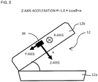
FIG. 5 is a diagram illustrating an inclination angle detected by a detection means; -
FIG. 6 is a plan view illustrating a schematic configuration of a storage portion; -
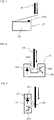
FIG. 7 is a diagram illustrating an example of an opened/closed state detection means using a micro switch; -
FIG. 8 is a diagram illustrating an example of the opened/closed state detection means using a transmissive photointerrupter; -
FIG. 9 is a diagram illustrating an example of the opened/closed state detection means using a reflective photointerrupter; -
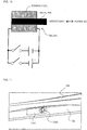
FIG. 10 is a diagram illustrating a configuration in a case where a solenoid type electronic key is employed as an unfastening mechanism; -
FIG. 11 is a diagram illustrating a closed state of a replacement cover provided in the roof box body; -
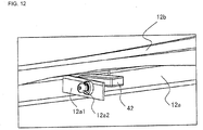
FIG. 12 is a diagram illustrating an opened state of the replacement cover provided in the roof box body; -
FIG. 13 is a diagram illustrating a configuration example of a manipulation screen in a case where a smart phone is used as a manipulation means; -
FIG. 14 is a flowchart illustrating a flow of a determination control in operations for opening, closing, and stopping the openable/closable cover using a control means; and -
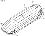
FIG. 15 is a diagram illustrating a state in which fins are provided on the openable/closable cover. - A roof box according to an embodiment of the present invention is now be described in details with reference to the accompanying drawings. First, a whole image configuration of the roof box according to an embodiment is illustrated in
FIG. 1 , and its individual components are described with reference toFIGS. 2 to 7 . Note that the embodiment described below provides one of preferable modes that the invention can be embodied, and its specific configuration is not particularly limited as long as each element exhibits its function. - The
roof box 10 according to this embodiment basically includes a roof box body 12 (refer toFIGS. 2 and3 ), opening/closing means 14a and 14b, a detection means 36, a control means 38, and a manipulation means 54. Theroof box body 12 has astorage portion 12a and an openable/closable cover 12b. - The opening/ closing means 14a and 14b are housed in the
roof box body 12 to perform an opening/closing operation of the openable/closable cover 12b described above. For example, anelectric actuator 16 having a motor or the like may be employed as the opening/closing means 14a and 14b. As illustrated inFIGS. 2 and3 , theelectric actuator 16 may have, for example, amain body 16a and arod 16b telescopable with respect to themain body 16a. In addition, theelectric actuator 16 may have shaft support portions 16a1 and 16b1 in a rear edge of the main body and a front edge of the rod, respectively. - In the
electric actuator 16 having such a configuration, alink 18 actuated in response to an operation of theelectric actuator 16 may be provided as follows. For example, as illustrated inFIGS. 2 and3 , a pantograph type link having upper andlower links electric actuator 16 may be employed. Specifically, theupper link 18b is divided in the vicinity of the center. Eachupper link 18b has an engagement portion for engagement with anupper base 20 provided in the openable/closable cover 12b, and an engagement portion for engagement with the shaft support portions 16al and 16b1 provided in themain body 16a or therod 16b of theelectric actuator 16. Similar to theupper link 18b, thelower link 18a is also divided in the vicinity of the center. In addition, eachlower link 18a has an engagement portion for engagement with alower base 22 provided in thestorage portion 12a and an engagement portion for engagement with the shaft support portions 16a1 and 16b1 provided in themain body 16a or therod 16b of theelectric actuator 16, respectively. - In this configuration of the opening/closing means 14a and 14b, as illustrated in
FIG. 3 , an opening angle between the upper andlower links rod 16b of theelectric actuator 16 is contracted. As a result, an interval between the upper andlower bases closable cover 12b has an opened state. Note that, when the opening/ closing operation is performed, any one of left and right sides of thestorage portion 12a and the openable/closable cover 12b inFIG. 2 is locked, so that it serves as a hinge (inFIG. 3 , the left side is locked). - The
roof box body 12 according to the embodiment has a pair of opening/closing means 14a and 14b provided in the front and rear sides of the vehicle travel direction as illustrated inFIG. 6 . Since the opening/closing means 14a and 14b are arranged in this manner, it is possible to suppress a distortion that may be generated when the openable/closable cover 12b is opened or closed. Alock mechanism 24 of thestorage portion 12a against the openable/closable cover 12b is illustrated inFIG. 4 . Thelock mechanism 24 basically includes a lockingmember 26 provided in the openable/closable cover 12b, and afastening portion 28 provided in thestorage portion 12a. The lockingmember 26 has alocking pin 26a. As thelocking pin 26a is locked to alock hook 28a provided in thefastening portion 28, a function of thelock mechanism 24 is exhibited. - The
lock hook 28a is pivotable around a support shaft 28a1 in the arrow direction "A". In addition, thelock hook 28a meshes with alock cam 28b, so that pivoting to the arrow direction "A" is interfered. Thelock cam 28b is pivoted around the support shaft 28b1 in the arrow direction "B" so that meshing with thelock hook 28a is released. - A
fastening release pole 30 is configured to pivot thelock cam 28b in the arrow direction "B" through thelink 30a. In this configuration, as thelocking pin 26a is engaged with thelock hook 28a, the lockingpin 26a is locked by thelock cam 28b. As a result, a locked state of thelock mechanism 24 is completed. Meanwhile, as thefastening release pole 30 is pivoted, thelock cam 28b is pivoted in the arrow direction "B" through thelink 30a, so that meshing with thelock hook 28a is released. As a result, thelock hook 28a can be freely pivoted in the arrow direction "A", so that the locked state of thelock mechanism 24 is released. - The roof box body according to the embodiment has a plurality of lock mechanisms 24 (a pair of front and
rear lock mechanisms 24 in the example ofFIG. 6 ) along each side (in each of left and right sides) of the vehicle travel direction as illustrated inFIG. 6 . Thelock hook 28a included in eachlock mechanism 24 is axially supported by a singlefastening release pole 30 in each side, so that all thelock mechanisms 24 are unlocked in each side by pivoting thefastening release pole 30. - Opened/closed state detection means 25A and 25B for detecting a closed state of the openable/
closable cover 12b are provided in the vicinity of thelock mechanism 24 of each side. The opened/closed state detection means 25A and 25B may include, for example, amicro switch 25a as illustrated inFIG. 7 or aphotointerrupter FIG. 8 or 9 . The opened/closed state detection means 25 including themicro switch 25a as illustrated inFIG. 7 can detect whether or not the openable/closable cover 12b is in a closed state as an end portion or a part of the openable/closable cover 12b presses a switch 25a1 of themicro switch 25a. In addition, thephotointerrupter 25b ofFIG. 8 can detect whether or not the openable/closable cover 12b is in a closed state as an end portion or a part of the openable/closable cover 12b is inserted into a slit 25b3 provided between a light emitting portion 25b1 and a light receiving portion 25b2, so that the light to the light receiving portion 25b2 is blocked. Furthermore, thephotointerrupter 25c ofFIG. 9 can detect whether or not the openable/closable cover 12b is in a closed state as an end portion or a part of the openable/closable cover 12b is arranged between a light emitting portion 25c1 and a light receiving portion 25c2, so that the light from the light emitting portion 25c1 is reflected on the light receiving portion 25c2. -
Unfastening mechanisms fastening release poles 30. The unfasteningmechanisms fastening release pole 30 caused by driving a motor by a motor, a gear, a wire, a belt, or the like. Since thefastening release pole 30 can be pivoted using a motor, it is possible to remotely control the operations from the fastening release operation to the opening operation of the openable/closable cover 12b. Note that, since the motor is driven in response to a fastening release signal, the motor is electrically connected to the control means 38. - A solenoid type electronic key may be employed as the unfastening mechanism as illustrated in
FIG. 10 . In the unfasteningmechanisms FIG. 10 , a metal pin disposed inside a coil may advance or retreat by switching a flow direction of the current against a solenoid coil. Therefore, the fastening release pole described above may be pivoted by virtue of movement of the metal pin, or the metal pin may function as thelock hook 28a of thelock mechanism 24 to substitute thelock mechanism 24. - The detection means 36 is a sensor for detecting acceleration for opening or closing the openable/
closable cover 12b described above. Therefore, the detection means 36 may include, for example, an acceleration sensor or the like. Note that, assuming that the acceleration of the open/close direction (Z-axis direction inFIG. 5 ) is detected by the acceleration sensor, if the acceleration of the Z-axis direction is constant, the acceleration becomes zero except for when starting and stopping the opening/closing operation. Therefore, if the acceleration is detected within a predetermined opening/closing operation time, it is possible to determine whether or not an abnormality occurs in the opening/closing operation on the basis of this acceleration signal. In addition, if the acceleration of the X-axis direction (vehicle travel direction) inFIG. 5 can be detected using the detection means 36, it is possible to detect movement of the vehicle. Therefore, it is possible to detect whether or not the openable/closable cover 12 is in the closed state when a vehicle moves on the basis of detection data of the opened/closed state detection means 25A and 25B or the unfasteningmechanisms - The control means 38 outputs a command signal for controlling opening/closing and stopping of the openable/
closable cover 12b and a notification signal for preventing a vehicle from moving while the openable/closable cover 12b is opened. The command signal from the control means 38 may include, for example, a command signal based on the opening/closing operation signal from the manipulation means 54 described below, a command signal for instructing an emergency stop of the openable/closable cover 12b, and the like. For this reason, the control means 38 is provided with aradio module 40 for transmitting or receiving a signal to or from the manipulation means 54. - The command signal for the emergency stop may be output, for example, in a case where a part of a human body or an article is nipped between the
storage portion 12a of theroof box body 12 and the openable/closable cover 12b, a case where the opening operation of the openable/closable cover 12b is interfered as the openable/closable cover 12b abuts on an obstacle that may exist thereover during its opening operation, or the like. The command signal for the emergency stop is output, for example, on the basis of the following determination. First, as the opening/closing operation signal is input from the manipulation means 54, and the command signal is output, the control means 38 detects acceleration for opening or closing the openable/closable cover 12b using the detection means 36. - In a case where the opening/closing operation of the openable/
closable cover 12b is normally performed, the acceleration except for a gravitational acceleration component detected by the detection means 36 becomes zero. In comparison, in a case where the opening/closing operation is interfered as an article is nipped between the openable/closable cover 12b and thestorage portion 12a, or the openable/closable cover 12b abuts on an obstacle, deceleration or acceleration (not zero) is detected within a predetermined opening/closing operation time. If the detection means 36 detects deceleration or acceleration within the opening/closing operation time, the control means 54 determines that nipping or abutting of an obstacle occurs and outputs the command signal for an emergency stop. - By performing such a control, it is possible to stop the opening/closing operation before a load becomes significant even when the openable/
closable cover 12b or thestorage portion 12a is distorted. Therefore, it is possible to ensure safety. Note that the command signal for the emergency stop may be a command signal for performing a reversing operation for the opening or closing operation. That is, if a command signal for the reversing operation is input during the opening operation, the openable/closable cover 12b is changed over to the closing operation. - In the
roof box 10 having such a configuration, power is consumed at least in the operation of the opening/closing means 14 and the operation of thelock mechanism 24. For this reason, a power supply means 42 such as a battery is provided in thestorage portion 12a. Since the power supply means 42 is provided, it is not necessary to provide a power line from the vehicle to theroof box body 12. As a result, it is possible to facilitate installation of theroof box body 12. - The power supply means 42 such as a battery may have a configuration in which the battery can be replaced one by one. Alternatively, for example, the power supply means 42 may be charged with power generated from a power generation means 44 such as a solar panel. In this configuration, it is possible to reduce an effort of replacing the power supply means 42 or connecting a charger and charging the battery when the power is completely consumed. In addition, a replacement cover 12a1 that allows only the power supply means 42 to be removed and replaced may be provided in the
storage portion 12a of the power supply means 42 separately from the opening and closing part of the openable/closable cover 12b as illustrated inFIGS. 11 and12 . Since only the power supply means 42 can be removed and replaced while the openable/closable cover 12b of theroof box body 12 is closed, it is possible to avoid theroof box body 12 from being closed and not opened when the power is completely consumed. Note that the replacement cover 12a1 may be provided with a mechanical key 12a2 for fastening for closing in order to prevent mischief or the like. - In a case where the power supply means 42 is arranged in the
roof box body 12, a part for supplying power to external devices such as a cigarettelighter socket 46 or aUSB charging connector 48 may be provided. This may improve convenience of theroof box body 12. Note that a chargingcontrol circuit 50 may be provided between the power supply means 42 and the power generation means 44 if the power generation means 44 is connected to the power supply means 42. In addition, naturally, apower circuit 52 for controlling supplied power is provided between the control means 38 that supplies power, the cigarettelighter socket 46, or theUSB charging connector 48 and the power supply means 42. - The manipulation means 54 serves as a remote controller for outputting an opening/closing operation signal to the control means 38 or a notification means that receives a notification signal from the control means 38. The manipulation means 54 may include, for example, a high-performance portable terminal such as a smart phone or a smart timepiece, a dedicated remote controller, or the like. In addition, a vehicle-mounted device may be used as the manipulation means. However, considering that the opening/closing operation of the
roof box body 12 is performed outside a vehicle, it is desirable that the function of the manipulation means 54 is provided in a portable terminal. -
FIG. 13 illustrates an example of a manipulation screen in a case where a smart phone is used as the manipulation means 54. On the manipulation screen, touch keys "RIGHT" and "LEFT" are displayed regarding which side of the roof box is opened. Here, the directions "RIGHT" and "LEFT" may be set to right and left sides of a vehicle along the longitudinal direction of theroof box body 12. - In addition, touch keys "OPEN" and "CLOSE" are displayed on the manipulation screen, regarding whether the openable/
closable cover 12b is opened or closed. The manipulation screen may include other display elements such as apanoramic view 54a of the roof box, abattery condition 54b of the power supply means 42 for operating theelectric actuator 16 or thelock mechanism 24, and the like. On such a manipulation screen, first, an operator selects a roof box opening/closing direction using the touch keys "RIGHT" and "LEFT", and then manipulates touch keys "OPEN" and "CLOSE" to instruct opening or closing of the openable/closable cover 12b. Note that the manipulation screen may have a function of providing an alarm or display for notifying that the openable/closable cover 12b is not closed when the notification signal is received from the control means 38. - Next, operations of the aforementioned configuration after the opening/ closing command of the
roof box 10 is issued is described. First, an operation for opening the openable/closable cover 12b is described. An operator selects an opening/closing direction of theroof box body 12 on the manipulation screen of the manipulation means 54. Then, an operator selects the touch key "OPEN" in order to open theroof box body 12. As the touch key "OPEN" is selected, an opening/closing operation signal including an opening/closing direction and an opening command of theroof box body 12 is transmitted to the control means 38. As the opening/closing operation signal is received, the control means 38 outputs a command signal for releasing the locked state of the opening side to the release-side lock mechanism 24. After thelock mechanism 24 is released in response to the output of the command signal, a command signal for performing an opening operation is output to theelectric actuator 16. - The control signal of the control means 38 in this case is output as illustrated in
FIG. 14 . First, an initialization process is performed as a preparatory process (S10). Then, detection information is acquired from the opened/closed state detection means 25A and 25B (S20). After the detection information is input from the opened/closed state detection means 25A and 25B, it is determined whether or not the opening/closing operation signal is received from the manipulation means 54 (S30). If the opening/closing operation signal is not received, the process returns to S20, and the detection information is acquired from the opened/closed state detection means 25A and 25B. Otherwise, if the opening/closing operation signal is received, a corresponding process is performed. - For example, if an opening/closing operation signal for opening the left side of the openable/
closable cover 12b is input, the process advances to S32, and it is determined whether the left and right sides of the openable/closable cover 12b are closed ("LL"), or whether only the left side is opened ("HL"). If the determination is YES, theunfastening mechanism 34b is activated to operate the opening/closing means 14a and 14b (S42). Meanwhile, if the determination of S32 is NO, an error signal is transmitted (S42a), and the process returns to S20. If an opening/closing operation signal for opening the right side of the openable/closable cover 12b is input after S30, the process advances to S36, and it is determined whether the left and right sides of the openable/closable cover 12b are closed ("LL"), or whether only the right side is opened ("LH"). If the determination is YES, theunfastening mechanism 34a is operated, and then the opening/closing means 14a and 14b are operated (S46). Otherwise, if the determination of S36 is NO, an error signal is transmitted (S46a), and the process returns to S20. - In such a control operation, the
roof box 10 is automatically opened or closed just by the manipulation performed on the manipulation means 54. Here, if the opening operation is interfered by an obstacle or the like that abuts while the openable/closable cover 12b is opened, the control means 38 outputs a command signal for stopping the opening operation to the electric actuator 16 (the opening/closing means 14a and 14b). As a result, the opening operation of the openable/closable cover 12b stops (S50). - Next, a closing operation of the openable/
closable cover 12b is described. The closing operation is for closing the openable/closable cover 12b having the opened state. Therefore, the touch key "CLOSE" is selected on the manipulation screen of the manipulation means 54. If the touch key "CLOSE" is selected, an opening/closing operation signal for closing the openable/closable cover 12b is transmitted to the control means 38. As the opening/closing operation signal is received, the control means 38 outputs a command signal for the closing operation to theelectric actuator 16. - As the control signal of the control means 38, for example, in a case where an opening/closing operation signal for closing the left side of the openable/
closable cover 12b is received, the process advances to S34, and it is determined whether or not only the left side of the openable/closable cover 12b is opened ("HL" state). If the determination is YES, the opening/closing means 14a and 14b are operated (S44). Otherwise, if the determination of S34 is NO, an error signal is transmitted (S44a), and the process returns to S20. - In a case where an opening/closing operation signal for closing the right side of the openable/
closable cover 12b is received, the process advances to S38, and it is determined whether or not only the right side of the openable/closable cover 12b is opened ("LH" state). If the determination is YES, the opening/closing means 14a and 14b are operated (S48). Otherwise, if the determination of S38 is NO, an error signal is transmitted (S48a), and the process returns to S20. - Here, in a case where the closing operation is interfered by a human body or obstacle nipped between the
storage portion 12a and the openable/closable cover 12b while the openable/closable cover 12b is closed, the control means 38 outputs a command signal for stopping the closing operation to the electric actuator 16 (the opening/closing means 14a and 14b). As a result, the closing operation of the openable/closable cover 12b stops (S50). - In the
roof box 10 according to an embodiment, when the detection means 36 detects that a vehicle moves in a state in which the closed state of the openable/closable cover 12b is not checked by the opened/closed state detection means 25a and 25b or a state in which the unfasteningmechanisms closable cover 12b is not in the closed state using an alarm or display. - In this manner, using the
roof box 10 according to this embodiment, it is possible to automatically perform operations from the lock release operation, to the opening operation, and to the closing operation just by selecting the touch key on the manipulation means 54. In addition, since whether or not an interference occurs in the opening or closing operation is determined on the basis of a change of acceleration at the time of the opening/closing operation of the openable/closable cover 12b, it is possible to stop the operation of the openable/closable cover 12b even when a load generated in theelectric actuator 16 is not increased due to a distortion generated in the openable/closable cover 12b. Therefore, it is possible to ensure safety of the opening/closing operation. - In a case where movement of a vehicle is detected while the openable/
closable cover 12b is not closed, the notification means such as the manipulation means 54 notifies an operator of this fact. Therefore, it is possible to avoid a vehicle from traveling while the openable/closable cover 12b is opened. In addition, since a portable terminal is employed as the manipulation means 54, it is possible to improve convenience of manipulation outside a vehicle. - Although a specific configuration of the
roof box body 12 is not described in the aforementioned embodiment, a fin 12b1 may be provided in the openable/closable cover 12b of theroof box body 12 as illustrated inFIG. 15 . It is possible to obtain a rectification effect by providing a plurality of fins 12b1 having a main surface along a vehicle travel direction on a surface of the openable/closable cover 12. As a result, it is possible to suppress turbulence generated in rear of theroof box body 12 and obtain effects such as improvement of fuel economy and rectilinear stability and reduction of noise. -
- 10
- roof box,
- 12
- roof box body,
- 12a
- storage portion,
- 12b
- openable/closable cover,
- 14
- opening/closing means,
- 16
- electric actuator,
- 16a
- main body,
- 16a1
- shaft support portion,
- 16b
- rod,
- 16b1
- shaft support portion,
- 18
- link,
- 18a
- lower link,
- 18b
- upper link,
- 20
- upper base,
- 22
- lower base,
- 24
- lock mechanism,
- 25
- opened/closed state detection means,
- 26
- locking member,
- 26a
- locking pin,
- 28
- fastening portion,
- 28a
- lock hook,
- 30
- fastening release pole,
- 34
- unfastening mechanism,
- 36
- detection means,
- 38
- control means,
- 40
- radio module,
- 42
- power supply means,
- 44
- power generation means,
- 46
- cigarette lighter socket,
- 48
- USB charging connector,
- 50
- charging control circuit,
- 52
- power circuit,
- 54
- manipulation means.
Claims (5)
- A roof box (10) comprising:a roof box body (12) having a storage portion (12a) and an openable/closable cover (12b);lock mechanisms (24) provided in both sides of the roof box body (12) along a travel direction to engage and fasten the storage portion (12a) and the openable/closable cover (12b) while the roof box body (12) is mounted;fastening release means (30) installed in each of the lock mechanisms (24) provided in both sides of the roof box body (12) to release the engagement and fastening;opening/closing means (14) configured to open or close the openable/closable cover (12b) with respect to any one of the lock mechanisms (24) when the engagement and fastening of the other lock mechanism (24) is released;a manipulation means (54) configured to transmit an opening/closing operation signal for selection of the lock mechanisms (24) for releasing the engagement and fastening and opening/closing of the openable/closable cover (12b) using the opening/closing means (14);characterized bya control means (38) configured to receive the opening/closing operation signal from the manipulation means (54), output an engagement release signal to the selected one of the lock mechanisms (24), and output an opening/closing signal for releasing the openable/ closable cover (12b) to the opening/closing means (14) after the engagement is released; andan opened/closed state detection means (25) that detects a side in which the openable/closable cover (12b) is released,wherein the control means (38) determines whether or not a side where engagement of the lock mechanism (24) is released matches a side detected by the opened/closed state detection means (25) as being released, anda command signal for stopping an opening/closing operation of the openable/closable cover (12b) is output to the opening/closing means (14) if the sides do not match as a result of the determination.
- The roof box (10) according to claim 1, further comprising a detection means (36) configured to detect an operation acceleration of the openable/closable cover (12b) while the opening/closing operation of the openable/closable cover (12b) using the opening/closing means (14) is performed at a constant speed,
wherein the control means (38) outputs a command signal for stopping or reversing the opening/ closing operation of the openable/ closable cover (12b) to the opening/closing means (14) when deceleration or acceleration generated by a force applied from an outside to the openable/closable cover (12b) is detected. - The roof box (10) according to any one of claims 1 to 2, wherein
the detection means (36) has an acceleration detection function in a direction along a vehicle travel direction,
the control means (38) has a function for outputting a notification signal in response to detection of the acceleration in a direction along the vehicle travel direction in at least one of a case where the opened/closed state detection means (25) detects that any one side of the openable/closable cover (12b) is released and a case where the engagement and fastening of the lock mechanism (24) is released, and
the manipulation means (54) has a notification function for receiving and notifying the notification signal from the control means (38). - The roof box (10) according to any one of claims 1 to 3, wherein the manipulation means (54) is a portable terminal having a communication unit capable of communicating with the control means (38).
- The roof box (10) according to any one of claims 1 to 4, wherein the roof box body (12) has a power supply means (42) configured to supply power necessary in the opening/closing operation, and
the roof box body (12) has an emergency opening/closing portion for extracting the power supply means (42) without opening the openable/closable cover (12b).
Applications Claiming Priority (2)
| Application Number | Priority Date | Filing Date | Title |
|---|---|---|---|
| JP2015211341A JP6562816B2 (en) | 2015-10-27 | 2015-10-27 | Roof box |
| PCT/JP2016/077020 WO2017073191A1 (en) | 2015-10-27 | 2016-09-13 | Roof box |
Publications (3)
| Publication Number | Publication Date |
|---|---|
| EP3369626A1 EP3369626A1 (en) | 2018-09-05 |
| EP3369626A4 EP3369626A4 (en) | 2018-09-26 |
| EP3369626B1 true EP3369626B1 (en) | 2019-11-06 |
Family
ID=58630226
Family Applications (1)
| Application Number | Title | Priority Date | Filing Date |
|---|---|---|---|
| EP16859428.1A Active EP3369626B1 (en) | 2015-10-27 | 2016-09-13 | Roof box |
Country Status (4)
| Country | Link |
|---|---|
| US (1) | US10464497B2 (en) |
| EP (1) | EP3369626B1 (en) |
| JP (1) | JP6562816B2 (en) |
| WO (1) | WO2017073191A1 (en) |
Families Citing this family (8)
| Publication number | Priority date | Publication date | Assignee | Title |
|---|---|---|---|---|
| US11753101B2 (en) * | 2018-04-27 | 2023-09-12 | FUELL Inc. | Electric saddle type vehicle with storage areas |
| EP3581435B1 (en) | 2018-06-13 | 2021-03-17 | Thule Sweden AB | Vehicle carrier box |
| EP3617000B1 (en) * | 2018-08-31 | 2020-10-21 | Thule Sweden AB | Cargo carrier |
| WO2020176858A2 (en) | 2019-02-28 | 2020-09-03 | FUELL Inc. | Electric saddle type vehicle |
| US10857948B2 (en) * | 2019-03-11 | 2020-12-08 | Stephen Sophorn Lim | Convertible vehicle storage container |
| CN110203142A (en) * | 2019-04-22 | 2019-09-06 | 滨州禾夏汽车用品有限公司 | A kind of automobile roof trunk |
| CN113306494A (en) * | 2021-06-29 | 2021-08-27 | 湖北省惠云电机有限公司 | Vehicle-mounted luggage case with two side doors |
| US11648886B2 (en) * | 2021-09-02 | 2023-05-16 | Ford Global Technologies, Llc | Rail mounted accessory clamping and locking system with power transmission and on/off command |
Family Cites Families (10)
| Publication number | Priority date | Publication date | Assignee | Title |
|---|---|---|---|---|
| US3640423A (en) * | 1970-07-01 | 1972-02-08 | Parker Ind Inc | Toolbox for pickup truck |
| DE4340083C2 (en) * | 1993-11-24 | 1996-05-23 | Huwil Werke Gmbh | Locking device for suitcases, in particular roof boxes for motor vehicles |
| JP3635309B2 (en) * | 1995-03-27 | 2005-04-06 | 株式会社カーメイト | Double-openable roof box |
| US5727835A (en) * | 1996-04-23 | 1998-03-17 | Douglas Dynamics, L.L.C. | Alarmed truck mounted tool box |
| JPH11129824A (en) | 1997-11-04 | 1999-05-18 | Pia Kk | Lock structure for roof box |
| US6793110B2 (en) * | 2002-12-19 | 2004-09-21 | William R. Hamilton | Motorcycle saddlebag assembly |
| US7503470B2 (en) * | 2003-01-28 | 2009-03-17 | Yakima Products, Inc. | Car top carrier |
| JP2006027475A (en) | 2004-07-16 | 2006-02-02 | Car Mate Mfg Co Ltd | Roof box with electric opening and closing mechanism |
| ES2338036T3 (en) * | 2006-11-13 | 2010-05-03 | Sau Leong Lim | KEY HOLDERS FOR A TWO-WHEEL VEHICLE. |
| DE202010012544U1 (en) | 2010-09-13 | 2010-11-18 | Hapro International B.V. | Car roof box |
-
2015
- 2015-10-27 JP JP2015211341A patent/JP6562816B2/en active Active
-
2016
- 2016-09-13 EP EP16859428.1A patent/EP3369626B1/en active Active
- 2016-09-13 WO PCT/JP2016/077020 patent/WO2017073191A1/en not_active Ceased
- 2016-09-13 US US15/769,352 patent/US10464497B2/en active Active
Non-Patent Citations (1)
| Title |
|---|
| None * |
Also Published As
| Publication number | Publication date |
|---|---|
| WO2017073191A1 (en) | 2017-05-04 |
| US10464497B2 (en) | 2019-11-05 |
| EP3369626A1 (en) | 2018-09-05 |
| EP3369626A4 (en) | 2018-09-26 |
| JP2017081403A (en) | 2017-05-18 |
| JP6562816B2 (en) | 2019-08-21 |
| US20180297536A1 (en) | 2018-10-18 |
Similar Documents
| Publication | Publication Date | Title |
|---|---|---|
| EP3369626A1 (en) | Roof box | |
| JP6981237B2 (en) | Vehicle charging system | |
| EP2980940A1 (en) | Charging cable locking device and controller | |
| EP3562172B1 (en) | Vehicle entry system and onboard device | |
| US20160076277A1 (en) | Vehicle door latch control device | |
| EP2578780B1 (en) | Power supply control device for electric actuators for door-related accessories in vehicle | |
| JP2010264847A (en) | Electric vehicle | |
| ITTO20110092A1 (en) | POWER SOCKET GROUP FOR RECHARGING ELECTRIC VEHICLE BATTERIES | |
| CN103171410A (en) | Locking mechanism for open roof construction and open roof construction with locking mechanism | |
| US10107012B2 (en) | Controller for energizing vehicle door lock indicator | |
| JP2020097816A (en) | Vehicle control device | |
| KR100719144B1 (en) | Drive device and door closer | |
| US8918249B2 (en) | Dual function electronic control unit | |
| JP6365169B2 (en) | vehicle | |
| US10704301B2 (en) | Safety exit assist system and method therefor | |
| CN101456364B (en) | vehicle seat slide | |
| KR20180072013A (en) | Switchger of tailgate for vehicle | |
| CN108621819A (en) | Vehicle | |
| EP2932950A1 (en) | Mounting device for object to be mounted | |
| JP6356593B2 (en) | Control device and control system for vehicle opening / closing body | |
| EP2685588A1 (en) | In-vehicle charger, and program therefor | |
| US9240276B2 (en) | Induction powered panels | |
| JP6056314B2 (en) | Vehicle energy supply port device | |
| US8276963B2 (en) | Storage structure having a lid | |
| KR20210082834A (en) | Apparatus for controlling door of vehicle |
Legal Events
| Date | Code | Title | Description |
|---|---|---|---|
| STAA | Information on the status of an ep patent application or granted ep patent |
Free format text: STATUS: THE INTERNATIONAL PUBLICATION HAS BEEN MADE |
|
| PUAI | Public reference made under article 153(3) epc to a published international application that has entered the european phase |
Free format text: ORIGINAL CODE: 0009012 |
|
| STAA | Information on the status of an ep patent application or granted ep patent |
Free format text: STATUS: REQUEST FOR EXAMINATION WAS MADE |
|
| 17P | Request for examination filed |
Effective date: 20180503 |
|
| AK | Designated contracting states |
Kind code of ref document: A1 Designated state(s): AL AT BE BG CH CY CZ DE DK EE ES FI FR GB GR HR HU IE IS IT LI LT LU LV MC MK MT NL NO PL PT RO RS SE SI SK SM TR |
|
| AX | Request for extension of the european patent |
Extension state: BA ME |
|
| A4 | Supplementary search report drawn up and despatched |
Effective date: 20180828 |
|
| RIC1 | Information provided on ipc code assigned before grant |
Ipc: B60R 9/055 20060101AFI20180822BHEP Ipc: B60R 16/04 20060101ALI20180822BHEP |
|
| DAV | Request for validation of the european patent (deleted) | ||
| DAX | Request for extension of the european patent (deleted) | ||
| GRAP | Despatch of communication of intention to grant a patent |
Free format text: ORIGINAL CODE: EPIDOSNIGR1 |
|
| STAA | Information on the status of an ep patent application or granted ep patent |
Free format text: STATUS: GRANT OF PATENT IS INTENDED |
|
| INTG | Intention to grant announced |
Effective date: 20190522 |
|
| GRAS | Grant fee paid |
Free format text: ORIGINAL CODE: EPIDOSNIGR3 |
|
| RIN1 | Information on inventor provided before grant (corrected) |
Inventor name: SUGIURA KEN Inventor name: TOMITA MOTOKI Inventor name: KISAKA DAISUKE Inventor name: KONDO TAKASHI Inventor name: AONO TATSUYUKI |
|
| GRAA | (expected) grant |
Free format text: ORIGINAL CODE: 0009210 |
|
| STAA | Information on the status of an ep patent application or granted ep patent |
Free format text: STATUS: THE PATENT HAS BEEN GRANTED |
|
| AK | Designated contracting states |
Kind code of ref document: B1 Designated state(s): AL AT BE BG CH CY CZ DE DK EE ES FI FR GB GR HR HU IE IS IT LI LT LU LV MC MK MT NL NO PL PT RO RS SE SI SK SM TR |
|
| REG | Reference to a national code |
Ref country code: GB Ref legal event code: FG4D |
|
| REG | Reference to a national code |
Ref country code: CH Ref legal event code: EP Ref country code: AT Ref legal event code: REF Ref document number: 1198309 Country of ref document: AT Kind code of ref document: T Effective date: 20191115 |
|
| REG | Reference to a national code |
Ref country code: DE Ref legal event code: R096 Ref document number: 602016024069 Country of ref document: DE |
|
| REG | Reference to a national code |
Ref country code: IE Ref legal event code: FG4D |
|
| REG | Reference to a national code |
Ref country code: NL Ref legal event code: MP Effective date: 20191106 |
|
| REG | Reference to a national code |
Ref country code: LT Ref legal event code: MG4D |
|
| PG25 | Lapsed in a contracting state [announced via postgrant information from national office to epo] |
Ref country code: PT Free format text: LAPSE BECAUSE OF FAILURE TO SUBMIT A TRANSLATION OF THE DESCRIPTION OR TO PAY THE FEE WITHIN THE PRESCRIBED TIME-LIMIT Effective date: 20200306 Ref country code: PL Free format text: LAPSE BECAUSE OF FAILURE TO SUBMIT A TRANSLATION OF THE DESCRIPTION OR TO PAY THE FEE WITHIN THE PRESCRIBED TIME-LIMIT Effective date: 20191106 Ref country code: LT Free format text: LAPSE BECAUSE OF FAILURE TO SUBMIT A TRANSLATION OF THE DESCRIPTION OR TO PAY THE FEE WITHIN THE PRESCRIBED TIME-LIMIT Effective date: 20191106 Ref country code: GR Free format text: LAPSE BECAUSE OF FAILURE TO SUBMIT A TRANSLATION OF THE DESCRIPTION OR TO PAY THE FEE WITHIN THE PRESCRIBED TIME-LIMIT Effective date: 20200207 Ref country code: NL Free format text: LAPSE BECAUSE OF FAILURE TO SUBMIT A TRANSLATION OF THE DESCRIPTION OR TO PAY THE FEE WITHIN THE PRESCRIBED TIME-LIMIT Effective date: 20191106 Ref country code: NO Free format text: LAPSE BECAUSE OF FAILURE TO SUBMIT A TRANSLATION OF THE DESCRIPTION OR TO PAY THE FEE WITHIN THE PRESCRIBED TIME-LIMIT Effective date: 20200206 Ref country code: SE Free format text: LAPSE BECAUSE OF FAILURE TO SUBMIT A TRANSLATION OF THE DESCRIPTION OR TO PAY THE FEE WITHIN THE PRESCRIBED TIME-LIMIT Effective date: 20191106 Ref country code: LV Free format text: LAPSE BECAUSE OF FAILURE TO SUBMIT A TRANSLATION OF THE DESCRIPTION OR TO PAY THE FEE WITHIN THE PRESCRIBED TIME-LIMIT Effective date: 20191106 Ref country code: FI Free format text: LAPSE BECAUSE OF FAILURE TO SUBMIT A TRANSLATION OF THE DESCRIPTION OR TO PAY THE FEE WITHIN THE PRESCRIBED TIME-LIMIT Effective date: 20191106 Ref country code: BG Free format text: LAPSE BECAUSE OF FAILURE TO SUBMIT A TRANSLATION OF THE DESCRIPTION OR TO PAY THE FEE WITHIN THE PRESCRIBED TIME-LIMIT Effective date: 20200206 |
|
| PG25 | Lapsed in a contracting state [announced via postgrant information from national office to epo] |
Ref country code: RS Free format text: LAPSE BECAUSE OF FAILURE TO SUBMIT A TRANSLATION OF THE DESCRIPTION OR TO PAY THE FEE WITHIN THE PRESCRIBED TIME-LIMIT Effective date: 20191106 Ref country code: IS Free format text: LAPSE BECAUSE OF FAILURE TO SUBMIT A TRANSLATION OF THE DESCRIPTION OR TO PAY THE FEE WITHIN THE PRESCRIBED TIME-LIMIT Effective date: 20200306 Ref country code: HR Free format text: LAPSE BECAUSE OF FAILURE TO SUBMIT A TRANSLATION OF THE DESCRIPTION OR TO PAY THE FEE WITHIN THE PRESCRIBED TIME-LIMIT Effective date: 20191106 |
|
| PG25 | Lapsed in a contracting state [announced via postgrant information from national office to epo] |
Ref country code: AL Free format text: LAPSE BECAUSE OF FAILURE TO SUBMIT A TRANSLATION OF THE DESCRIPTION OR TO PAY THE FEE WITHIN THE PRESCRIBED TIME-LIMIT Effective date: 20191106 |
|
| PG25 | Lapsed in a contracting state [announced via postgrant information from national office to epo] |
Ref country code: EE Free format text: LAPSE BECAUSE OF FAILURE TO SUBMIT A TRANSLATION OF THE DESCRIPTION OR TO PAY THE FEE WITHIN THE PRESCRIBED TIME-LIMIT Effective date: 20191106 Ref country code: DK Free format text: LAPSE BECAUSE OF FAILURE TO SUBMIT A TRANSLATION OF THE DESCRIPTION OR TO PAY THE FEE WITHIN THE PRESCRIBED TIME-LIMIT Effective date: 20191106 Ref country code: RO Free format text: LAPSE BECAUSE OF FAILURE TO SUBMIT A TRANSLATION OF THE DESCRIPTION OR TO PAY THE FEE WITHIN THE PRESCRIBED TIME-LIMIT Effective date: 20191106 Ref country code: ES Free format text: LAPSE BECAUSE OF FAILURE TO SUBMIT A TRANSLATION OF THE DESCRIPTION OR TO PAY THE FEE WITHIN THE PRESCRIBED TIME-LIMIT Effective date: 20191106 Ref country code: CZ Free format text: LAPSE BECAUSE OF FAILURE TO SUBMIT A TRANSLATION OF THE DESCRIPTION OR TO PAY THE FEE WITHIN THE PRESCRIBED TIME-LIMIT Effective date: 20191106 |
|
| REG | Reference to a national code |
Ref country code: DE Ref legal event code: R097 Ref document number: 602016024069 Country of ref document: DE |
|
| REG | Reference to a national code |
Ref country code: AT Ref legal event code: MK05 Ref document number: 1198309 Country of ref document: AT Kind code of ref document: T Effective date: 20191106 |
|
| PG25 | Lapsed in a contracting state [announced via postgrant information from national office to epo] |
Ref country code: SM Free format text: LAPSE BECAUSE OF FAILURE TO SUBMIT A TRANSLATION OF THE DESCRIPTION OR TO PAY THE FEE WITHIN THE PRESCRIBED TIME-LIMIT Effective date: 20191106 Ref country code: SK Free format text: LAPSE BECAUSE OF FAILURE TO SUBMIT A TRANSLATION OF THE DESCRIPTION OR TO PAY THE FEE WITHIN THE PRESCRIBED TIME-LIMIT Effective date: 20191106 |
|
| PLBE | No opposition filed within time limit |
Free format text: ORIGINAL CODE: 0009261 |
|
| STAA | Information on the status of an ep patent application or granted ep patent |
Free format text: STATUS: NO OPPOSITION FILED WITHIN TIME LIMIT |
|
| 26N | No opposition filed |
Effective date: 20200807 |
|
| PG25 | Lapsed in a contracting state [announced via postgrant information from national office to epo] |
Ref country code: SI Free format text: LAPSE BECAUSE OF FAILURE TO SUBMIT A TRANSLATION OF THE DESCRIPTION OR TO PAY THE FEE WITHIN THE PRESCRIBED TIME-LIMIT Effective date: 20191106 Ref country code: AT Free format text: LAPSE BECAUSE OF FAILURE TO SUBMIT A TRANSLATION OF THE DESCRIPTION OR TO PAY THE FEE WITHIN THE PRESCRIBED TIME-LIMIT Effective date: 20191106 |
|
| REG | Reference to a national code |
Ref country code: CH Ref legal event code: PL |
|
| REG | Reference to a national code |
Ref country code: BE Ref legal event code: MM Effective date: 20200930 |
|
| PG25 | Lapsed in a contracting state [announced via postgrant information from national office to epo] |
Ref country code: LU Free format text: LAPSE BECAUSE OF NON-PAYMENT OF DUE FEES Effective date: 20200913 |
|
| PG25 | Lapsed in a contracting state [announced via postgrant information from national office to epo] |
Ref country code: IE Free format text: LAPSE BECAUSE OF NON-PAYMENT OF DUE FEES Effective date: 20200913 Ref country code: LI Free format text: LAPSE BECAUSE OF NON-PAYMENT OF DUE FEES Effective date: 20200930 Ref country code: CH Free format text: LAPSE BECAUSE OF NON-PAYMENT OF DUE FEES Effective date: 20200930 Ref country code: BE Free format text: LAPSE BECAUSE OF NON-PAYMENT OF DUE FEES Effective date: 20200930 |
|
| PG25 | Lapsed in a contracting state [announced via postgrant information from national office to epo] |
Ref country code: TR Free format text: LAPSE BECAUSE OF FAILURE TO SUBMIT A TRANSLATION OF THE DESCRIPTION OR TO PAY THE FEE WITHIN THE PRESCRIBED TIME-LIMIT Effective date: 20191106 Ref country code: MT Free format text: LAPSE BECAUSE OF FAILURE TO SUBMIT A TRANSLATION OF THE DESCRIPTION OR TO PAY THE FEE WITHIN THE PRESCRIBED TIME-LIMIT Effective date: 20191106 Ref country code: CY Free format text: LAPSE BECAUSE OF FAILURE TO SUBMIT A TRANSLATION OF THE DESCRIPTION OR TO PAY THE FEE WITHIN THE PRESCRIBED TIME-LIMIT Effective date: 20191106 |
|
| PG25 | Lapsed in a contracting state [announced via postgrant information from national office to epo] |
Ref country code: MK Free format text: LAPSE BECAUSE OF FAILURE TO SUBMIT A TRANSLATION OF THE DESCRIPTION OR TO PAY THE FEE WITHIN THE PRESCRIBED TIME-LIMIT Effective date: 20191106 Ref country code: MC Free format text: LAPSE BECAUSE OF FAILURE TO SUBMIT A TRANSLATION OF THE DESCRIPTION OR TO PAY THE FEE WITHIN THE PRESCRIBED TIME-LIMIT Effective date: 20191106 |
|
| PGFP | Annual fee paid to national office [announced via postgrant information from national office to epo] |
Ref country code: DE Payment date: 20240829 Year of fee payment: 9 |
|
| PGFP | Annual fee paid to national office [announced via postgrant information from national office to epo] |
Ref country code: GB Payment date: 20240922 Year of fee payment: 9 |
|
| PGFP | Annual fee paid to national office [announced via postgrant information from national office to epo] |
Ref country code: FR Payment date: 20240924 Year of fee payment: 9 |
|
| PGFP | Annual fee paid to national office [announced via postgrant information from national office to epo] |
Ref country code: IT Payment date: 20240926 Year of fee payment: 9 |