EP3369600A1 - Vehicle with pivoting fuel gas tank in case of longitudinal crash - Google Patents
Vehicle with pivoting fuel gas tank in case of longitudinal crash Download PDFInfo
- Publication number
- EP3369600A1 EP3369600A1 EP18158761.9A EP18158761A EP3369600A1 EP 3369600 A1 EP3369600 A1 EP 3369600A1 EP 18158761 A EP18158761 A EP 18158761A EP 3369600 A1 EP3369600 A1 EP 3369600A1
- Authority
- EP
- European Patent Office
- Prior art keywords
- vehicle
- fuel tank
- end portion
- supporting
- supporting portion
- Prior art date
- Legal status (The legal status is an assumption and is not a legal conclusion. Google has not performed a legal analysis and makes no representation as to the accuracy of the status listed.)
- Granted
Links
- 239000002737 fuel gas Substances 0.000 title claims description 4
- 239000002828 fuel tank Substances 0.000 claims abstract description 98
- 239000000446 fuel Substances 0.000 claims description 60
- 230000002093 peripheral effect Effects 0.000 claims description 22
- 230000007246 mechanism Effects 0.000 claims description 19
- 238000006073 displacement reaction Methods 0.000 claims description 10
- 239000000463 material Substances 0.000 claims description 8
- 150000001875 compounds Chemical class 0.000 claims 1
- 239000001257 hydrogen Substances 0.000 description 108
- 229910052739 hydrogen Inorganic materials 0.000 description 108
- UFHFLCQGNIYNRP-UHFFFAOYSA-N Hydrogen Chemical compound [H][H] UFHFLCQGNIYNRP-UHFFFAOYSA-N 0.000 description 107
- 230000009467 reduction Effects 0.000 description 10
- QVGXLLKOCUKJST-UHFFFAOYSA-N atomic oxygen Chemical compound [O] QVGXLLKOCUKJST-UHFFFAOYSA-N 0.000 description 4
- VNWKTOKETHGBQD-UHFFFAOYSA-N methane Chemical compound C VNWKTOKETHGBQD-UHFFFAOYSA-N 0.000 description 4
- 239000001301 oxygen Substances 0.000 description 4
- 229910052760 oxygen Inorganic materials 0.000 description 4
- 238000006243 chemical reaction Methods 0.000 description 3
- 239000011248 coating agent Substances 0.000 description 3
- 238000000576 coating method Methods 0.000 description 3
- 230000004888 barrier function Effects 0.000 description 2
- 239000003054 catalyst Substances 0.000 description 2
- 150000002431 hydrogen Chemical class 0.000 description 2
- 239000003345 natural gas Substances 0.000 description 2
- 229920002430 Fibre-reinforced plastic Polymers 0.000 description 1
- 229910052782 aluminium Inorganic materials 0.000 description 1
- XAGFODPZIPBFFR-UHFFFAOYSA-N aluminium Chemical compound [Al] XAGFODPZIPBFFR-UHFFFAOYSA-N 0.000 description 1
- 230000008878 coupling Effects 0.000 description 1
- 238000010168 coupling process Methods 0.000 description 1
- 238000005859 coupling reaction Methods 0.000 description 1
- 238000002474 experimental method Methods 0.000 description 1
- 239000011151 fibre-reinforced plastic Substances 0.000 description 1
- 239000007789 gas Substances 0.000 description 1
- 230000012447 hatching Effects 0.000 description 1
- 239000012528 membrane Substances 0.000 description 1
- 229910052751 metal Inorganic materials 0.000 description 1
- 239000002184 metal Substances 0.000 description 1
- 238000000034 method Methods 0.000 description 1
- 230000004048 modification Effects 0.000 description 1
- 238000012986 modification Methods 0.000 description 1
- 239000007800 oxidant agent Substances 0.000 description 1
- 239000005518 polymer electrolyte Substances 0.000 description 1
- 238000010248 power generation Methods 0.000 description 1
- 239000011347 resin Substances 0.000 description 1
- 229920005989 resin Polymers 0.000 description 1
- 230000000452 restraining effect Effects 0.000 description 1
- 238000010008 shearing Methods 0.000 description 1
- 238000004088 simulation Methods 0.000 description 1
- 239000007787 solid Substances 0.000 description 1
Images


Classifications
-
- B—PERFORMING OPERATIONS; TRANSPORTING
- B60—VEHICLES IN GENERAL
- B60L—PROPULSION OF ELECTRICALLY-PROPELLED VEHICLES; SUPPLYING ELECTRIC POWER FOR AUXILIARY EQUIPMENT OF ELECTRICALLY-PROPELLED VEHICLES; ELECTRODYNAMIC BRAKE SYSTEMS FOR VEHICLES IN GENERAL; MAGNETIC SUSPENSION OR LEVITATION FOR VEHICLES; MONITORING OPERATING VARIABLES OF ELECTRICALLY-PROPELLED VEHICLES; ELECTRIC SAFETY DEVICES FOR ELECTRICALLY-PROPELLED VEHICLES
- B60L50/00—Electric propulsion with power supplied within the vehicle
- B60L50/50—Electric propulsion with power supplied within the vehicle using propulsion power supplied by batteries or fuel cells
- B60L50/70—Electric propulsion with power supplied within the vehicle using propulsion power supplied by batteries or fuel cells using power supplied by fuel cells
- B60L50/72—Constructional details of fuel cells specially adapted for electric vehicles
-
- B—PERFORMING OPERATIONS; TRANSPORTING
- B60—VEHICLES IN GENERAL
- B60K—ARRANGEMENT OR MOUNTING OF PROPULSION UNITS OR OF TRANSMISSIONS IN VEHICLES; ARRANGEMENT OR MOUNTING OF PLURAL DIVERSE PRIME-MOVERS IN VEHICLES; AUXILIARY DRIVES FOR VEHICLES; INSTRUMENTATION OR DASHBOARDS FOR VEHICLES; ARRANGEMENTS IN CONNECTION WITH COOLING, AIR INTAKE, GAS EXHAUST OR FUEL SUPPLY OF PROPULSION UNITS IN VEHICLES
- B60K1/00—Arrangement or mounting of electrical propulsion units
- B60K1/04—Arrangement or mounting of electrical propulsion units of the electric storage means for propulsion
-
- B—PERFORMING OPERATIONS; TRANSPORTING
- B60—VEHICLES IN GENERAL
- B60K—ARRANGEMENT OR MOUNTING OF PROPULSION UNITS OR OF TRANSMISSIONS IN VEHICLES; ARRANGEMENT OR MOUNTING OF PLURAL DIVERSE PRIME-MOVERS IN VEHICLES; AUXILIARY DRIVES FOR VEHICLES; INSTRUMENTATION OR DASHBOARDS FOR VEHICLES; ARRANGEMENTS IN CONNECTION WITH COOLING, AIR INTAKE, GAS EXHAUST OR FUEL SUPPLY OF PROPULSION UNITS IN VEHICLES
- B60K15/00—Arrangement in connection with fuel supply of combustion engines or other fuel consuming energy converters, e.g. fuel cells; Mounting or construction of fuel tanks
- B60K15/03—Fuel tanks
- B60K15/03006—Gas tanks
-
- B—PERFORMING OPERATIONS; TRANSPORTING
- B60—VEHICLES IN GENERAL
- B60K—ARRANGEMENT OR MOUNTING OF PROPULSION UNITS OR OF TRANSMISSIONS IN VEHICLES; ARRANGEMENT OR MOUNTING OF PLURAL DIVERSE PRIME-MOVERS IN VEHICLES; AUXILIARY DRIVES FOR VEHICLES; INSTRUMENTATION OR DASHBOARDS FOR VEHICLES; ARRANGEMENTS IN CONNECTION WITH COOLING, AIR INTAKE, GAS EXHAUST OR FUEL SUPPLY OF PROPULSION UNITS IN VEHICLES
- B60K15/00—Arrangement in connection with fuel supply of combustion engines or other fuel consuming energy converters, e.g. fuel cells; Mounting or construction of fuel tanks
- B60K15/03—Fuel tanks
- B60K15/063—Arrangement of tanks
- B60K15/067—Mounting of tanks
- B60K15/07—Mounting of tanks of gas tanks
-
- B—PERFORMING OPERATIONS; TRANSPORTING
- B60—VEHICLES IN GENERAL
- B60K—ARRANGEMENT OR MOUNTING OF PROPULSION UNITS OR OF TRANSMISSIONS IN VEHICLES; ARRANGEMENT OR MOUNTING OF PLURAL DIVERSE PRIME-MOVERS IN VEHICLES; AUXILIARY DRIVES FOR VEHICLES; INSTRUMENTATION OR DASHBOARDS FOR VEHICLES; ARRANGEMENTS IN CONNECTION WITH COOLING, AIR INTAKE, GAS EXHAUST OR FUEL SUPPLY OF PROPULSION UNITS IN VEHICLES
- B60K7/00—Disposition of motor in, or adjacent to, traction wheel
- B60K7/0007—Disposition of motor in, or adjacent to, traction wheel the motor being electric
-
- B—PERFORMING OPERATIONS; TRANSPORTING
- B60—VEHICLES IN GENERAL
- B60L—PROPULSION OF ELECTRICALLY-PROPELLED VEHICLES; SUPPLYING ELECTRIC POWER FOR AUXILIARY EQUIPMENT OF ELECTRICALLY-PROPELLED VEHICLES; ELECTRODYNAMIC BRAKE SYSTEMS FOR VEHICLES IN GENERAL; MAGNETIC SUSPENSION OR LEVITATION FOR VEHICLES; MONITORING OPERATING VARIABLES OF ELECTRICALLY-PROPELLED VEHICLES; ELECTRIC SAFETY DEVICES FOR ELECTRICALLY-PROPELLED VEHICLES
- B60L50/00—Electric propulsion with power supplied within the vehicle
- B60L50/50—Electric propulsion with power supplied within the vehicle using propulsion power supplied by batteries or fuel cells
- B60L50/60—Electric propulsion with power supplied within the vehicle using propulsion power supplied by batteries or fuel cells using power supplied by batteries
- B60L50/66—Arrangements of batteries
-
- B—PERFORMING OPERATIONS; TRANSPORTING
- B60—VEHICLES IN GENERAL
- B60L—PROPULSION OF ELECTRICALLY-PROPELLED VEHICLES; SUPPLYING ELECTRIC POWER FOR AUXILIARY EQUIPMENT OF ELECTRICALLY-PROPELLED VEHICLES; ELECTRODYNAMIC BRAKE SYSTEMS FOR VEHICLES IN GENERAL; MAGNETIC SUSPENSION OR LEVITATION FOR VEHICLES; MONITORING OPERATING VARIABLES OF ELECTRICALLY-PROPELLED VEHICLES; ELECTRIC SAFETY DEVICES FOR ELECTRICALLY-PROPELLED VEHICLES
- B60L50/00—Electric propulsion with power supplied within the vehicle
- B60L50/50—Electric propulsion with power supplied within the vehicle using propulsion power supplied by batteries or fuel cells
- B60L50/70—Electric propulsion with power supplied within the vehicle using propulsion power supplied by batteries or fuel cells using power supplied by fuel cells
- B60L50/71—Arrangement of fuel cells within vehicles specially adapted for electric vehicles
-
- B—PERFORMING OPERATIONS; TRANSPORTING
- B60—VEHICLES IN GENERAL
- B60R—VEHICLES, VEHICLE FITTINGS, OR VEHICLE PARTS, NOT OTHERWISE PROVIDED FOR
- B60R16/00—Electric or fluid circuits specially adapted for vehicles and not otherwise provided for; Arrangement of elements of electric or fluid circuits specially adapted for vehicles and not otherwise provided for
- B60R16/02—Electric or fluid circuits specially adapted for vehicles and not otherwise provided for; Arrangement of elements of electric or fluid circuits specially adapted for vehicles and not otherwise provided for electric constitutive elements
-
- B—PERFORMING OPERATIONS; TRANSPORTING
- B60—VEHICLES IN GENERAL
- B60K—ARRANGEMENT OR MOUNTING OF PROPULSION UNITS OR OF TRANSMISSIONS IN VEHICLES; ARRANGEMENT OR MOUNTING OF PLURAL DIVERSE PRIME-MOVERS IN VEHICLES; AUXILIARY DRIVES FOR VEHICLES; INSTRUMENTATION OR DASHBOARDS FOR VEHICLES; ARRANGEMENTS IN CONNECTION WITH COOLING, AIR INTAKE, GAS EXHAUST OR FUEL SUPPLY OF PROPULSION UNITS IN VEHICLES
- B60K1/00—Arrangement or mounting of electrical propulsion units
- B60K2001/001—Arrangement or mounting of electrical propulsion units one motor mounted on a propulsion axle for rotating right and left wheels of this axle
-
- B—PERFORMING OPERATIONS; TRANSPORTING
- B60—VEHICLES IN GENERAL
- B60K—ARRANGEMENT OR MOUNTING OF PROPULSION UNITS OR OF TRANSMISSIONS IN VEHICLES; ARRANGEMENT OR MOUNTING OF PLURAL DIVERSE PRIME-MOVERS IN VEHICLES; AUXILIARY DRIVES FOR VEHICLES; INSTRUMENTATION OR DASHBOARDS FOR VEHICLES; ARRANGEMENTS IN CONNECTION WITH COOLING, AIR INTAKE, GAS EXHAUST OR FUEL SUPPLY OF PROPULSION UNITS IN VEHICLES
- B60K1/00—Arrangement or mounting of electrical propulsion units
- B60K1/04—Arrangement or mounting of electrical propulsion units of the electric storage means for propulsion
- B60K2001/0405—Arrangement or mounting of electrical propulsion units of the electric storage means for propulsion characterised by their position
- B60K2001/0411—Arrangement in the front part of the vehicle
-
- B—PERFORMING OPERATIONS; TRANSPORTING
- B60—VEHICLES IN GENERAL
- B60K—ARRANGEMENT OR MOUNTING OF PROPULSION UNITS OR OF TRANSMISSIONS IN VEHICLES; ARRANGEMENT OR MOUNTING OF PLURAL DIVERSE PRIME-MOVERS IN VEHICLES; AUXILIARY DRIVES FOR VEHICLES; INSTRUMENTATION OR DASHBOARDS FOR VEHICLES; ARRANGEMENTS IN CONNECTION WITH COOLING, AIR INTAKE, GAS EXHAUST OR FUEL SUPPLY OF PROPULSION UNITS IN VEHICLES
- B60K1/00—Arrangement or mounting of electrical propulsion units
- B60K1/04—Arrangement or mounting of electrical propulsion units of the electric storage means for propulsion
- B60K2001/0405—Arrangement or mounting of electrical propulsion units of the electric storage means for propulsion characterised by their position
- B60K2001/0416—Arrangement in the rear part of the vehicle
-
- B—PERFORMING OPERATIONS; TRANSPORTING
- B60—VEHICLES IN GENERAL
- B60K—ARRANGEMENT OR MOUNTING OF PROPULSION UNITS OR OF TRANSMISSIONS IN VEHICLES; ARRANGEMENT OR MOUNTING OF PLURAL DIVERSE PRIME-MOVERS IN VEHICLES; AUXILIARY DRIVES FOR VEHICLES; INSTRUMENTATION OR DASHBOARDS FOR VEHICLES; ARRANGEMENTS IN CONNECTION WITH COOLING, AIR INTAKE, GAS EXHAUST OR FUEL SUPPLY OF PROPULSION UNITS IN VEHICLES
- B60K15/00—Arrangement in connection with fuel supply of combustion engines or other fuel consuming energy converters, e.g. fuel cells; Mounting or construction of fuel tanks
- B60K15/03—Fuel tanks
- B60K2015/03309—Tanks specially adapted for particular fuels
- B60K2015/03315—Tanks specially adapted for particular fuels for hydrogen
-
- B—PERFORMING OPERATIONS; TRANSPORTING
- B60—VEHICLES IN GENERAL
- B60K—ARRANGEMENT OR MOUNTING OF PROPULSION UNITS OR OF TRANSMISSIONS IN VEHICLES; ARRANGEMENT OR MOUNTING OF PLURAL DIVERSE PRIME-MOVERS IN VEHICLES; AUXILIARY DRIVES FOR VEHICLES; INSTRUMENTATION OR DASHBOARDS FOR VEHICLES; ARRANGEMENTS IN CONNECTION WITH COOLING, AIR INTAKE, GAS EXHAUST OR FUEL SUPPLY OF PROPULSION UNITS IN VEHICLES
- B60K15/00—Arrangement in connection with fuel supply of combustion engines or other fuel consuming energy converters, e.g. fuel cells; Mounting or construction of fuel tanks
- B60K15/03—Fuel tanks
- B60K15/063—Arrangement of tanks
- B60K2015/0637—Arrangement of tanks the fuel tank is arranged in the front of the vehicle
-
- B—PERFORMING OPERATIONS; TRANSPORTING
- B60—VEHICLES IN GENERAL
- B60K—ARRANGEMENT OR MOUNTING OF PROPULSION UNITS OR OF TRANSMISSIONS IN VEHICLES; ARRANGEMENT OR MOUNTING OF PLURAL DIVERSE PRIME-MOVERS IN VEHICLES; AUXILIARY DRIVES FOR VEHICLES; INSTRUMENTATION OR DASHBOARDS FOR VEHICLES; ARRANGEMENTS IN CONNECTION WITH COOLING, AIR INTAKE, GAS EXHAUST OR FUEL SUPPLY OF PROPULSION UNITS IN VEHICLES
- B60K15/00—Arrangement in connection with fuel supply of combustion engines or other fuel consuming energy converters, e.g. fuel cells; Mounting or construction of fuel tanks
- B60K15/03—Fuel tanks
- B60K15/063—Arrangement of tanks
- B60K2015/0638—Arrangement of tanks the fuel tank is arranged in the rear of the vehicle
-
- B—PERFORMING OPERATIONS; TRANSPORTING
- B60—VEHICLES IN GENERAL
- B60K—ARRANGEMENT OR MOUNTING OF PROPULSION UNITS OR OF TRANSMISSIONS IN VEHICLES; ARRANGEMENT OR MOUNTING OF PLURAL DIVERSE PRIME-MOVERS IN VEHICLES; AUXILIARY DRIVES FOR VEHICLES; INSTRUMENTATION OR DASHBOARDS FOR VEHICLES; ARRANGEMENTS IN CONNECTION WITH COOLING, AIR INTAKE, GAS EXHAUST OR FUEL SUPPLY OF PROPULSION UNITS IN VEHICLES
- B60K15/00—Arrangement in connection with fuel supply of combustion engines or other fuel consuming energy converters, e.g. fuel cells; Mounting or construction of fuel tanks
- B60K15/03—Fuel tanks
- B60K15/063—Arrangement of tanks
- B60K15/067—Mounting of tanks
- B60K2015/0675—Mounting of tanks allowing deflection movements of the tank in case of a crash
-
- B—PERFORMING OPERATIONS; TRANSPORTING
- B60—VEHICLES IN GENERAL
- B60Y—INDEXING SCHEME RELATING TO ASPECTS CROSS-CUTTING VEHICLE TECHNOLOGY
- B60Y2306/00—Other features of vehicle sub-units
- B60Y2306/01—Reducing damages in case of crash, e.g. by improving battery protection
-
- Y—GENERAL TAGGING OF NEW TECHNOLOGICAL DEVELOPMENTS; GENERAL TAGGING OF CROSS-SECTIONAL TECHNOLOGIES SPANNING OVER SEVERAL SECTIONS OF THE IPC; TECHNICAL SUBJECTS COVERED BY FORMER USPC CROSS-REFERENCE ART COLLECTIONS [XRACs] AND DIGESTS
- Y02—TECHNOLOGIES OR APPLICATIONS FOR MITIGATION OR ADAPTATION AGAINST CLIMATE CHANGE
- Y02T—CLIMATE CHANGE MITIGATION TECHNOLOGIES RELATED TO TRANSPORTATION
- Y02T10/00—Road transport of goods or passengers
- Y02T10/60—Other road transportation technologies with climate change mitigation effect
- Y02T10/70—Energy storage systems for electromobility, e.g. batteries
-
- Y—GENERAL TAGGING OF NEW TECHNOLOGICAL DEVELOPMENTS; GENERAL TAGGING OF CROSS-SECTIONAL TECHNOLOGIES SPANNING OVER SEVERAL SECTIONS OF THE IPC; TECHNICAL SUBJECTS COVERED BY FORMER USPC CROSS-REFERENCE ART COLLECTIONS [XRACs] AND DIGESTS
- Y02—TECHNOLOGIES OR APPLICATIONS FOR MITIGATION OR ADAPTATION AGAINST CLIMATE CHANGE
- Y02T—CLIMATE CHANGE MITIGATION TECHNOLOGIES RELATED TO TRANSPORTATION
- Y02T90/00—Enabling technologies or technologies with a potential or indirect contribution to GHG emissions mitigation
- Y02T90/40—Application of hydrogen technology to transportation, e.g. using fuel cells
Definitions
- the present invention relates to a vehicle in which an electrical device having a high-voltage part accommodated in a case, is disposed at a vehicle front portion or a vehicle rear portion.
- various electrical devices having a high-voltage part accommodated in a case are mounted.
- the various electrical devices include, for example, a battery unit in which a battery serving as a cell is accommodated in a battery case, a power control unit in which a converter or an inverter is accommodated in the case, a fuel cell in which a cell stack is accommodated in the case, and a motor drive unit in which a motor serving as a driving source is accommodated in the case.
- various fuel tanks in which fuel gas is stored are also mounted.
- the various fuel tanks include, for example, a tank that stores compressed natural gas in a natural gas vehicle, a tank that stores hydrogen gas in a hydrogen car, and a tank that stores the fuel gas to be supplied to a fuel cell in a fuel cell vehicle.
- International Publication WO2015/185184 discloses a fuel cell vehicle in which a motor drive unit is disposed at a vehicle rear portion so as to extend over rear wheel vehicle axles.
- Two fuel tanks are disposed in front of and behind the motor drive unit, respectively, such that their longitudinal directions are oriented along a vehicle width direction (i.e., perpendicular to a vehicle longitudinal direction).
- a high-voltage part for example, a motor, a terminal portion, or the like
- a coating or a cover in order to prevent an electric shock or the like may be peeled off (exposes).
- a state where the high-voltage part can be touched may occur.
- the exposed high-voltage part may be damaged by contacting a peripheral component.
- the exposure of the high-voltage part as described above is not limited to the layout disclosed in International Publication WO2015/185184 , and may occur, for example, even during a front collision in a fuel cell vehicle in which a fuel tank is disposed in front of the motor drive unit provided in the vehicle front portion. Additionally, the above described exposure is not limited to the fuel cell vehicle, and is also applicable to, for example, a front collision (or a rear collision) in other vehicles in which fuel tanks are disposed in front of (or behind) an electrical device, such as a battery unit, which is provided in the vehicle front portion (or vehicle rear portion).
- the invention provides a technique for further reducing the exposure of a high-voltage part following a front collision or a rear collision, in a vehicle having an electrical device in which the high-voltage part is accommodated in a case is disposed at a vehicle front portion or a vehicle rear portion and a fuel tank is disposed outward of the electrical device in a vehicle front-rear direction.
- displacement of the fuel tank during a front collision or a rear collision is controlled so that the fuel tank does not contact a peripheral part of the high-voltage part in the electrical device.
- aspects of the invention relate to a vehicle including an electrical device in which a high-voltage part is accommodated in a case, and a fuel tank in which fuel (e.g., gaseous fuel) is stored.
- the electrical device is disposed at a vehicle front portion or a vehicle rear portion.
- the case has a first side end in a vehicle width direction and a second side end opposite to the first side end.
- the fuel tank is disposed outward of the electrical device in a vehicle front-rear direction so as to extend in the vehicle width direction.
- the high-voltage part is disposed near the first side end of the case in the vehicle width direction within the case.
- the fuel tank has a first end portion in the vehicle width direction and a second end portion opposite to the first end portion.
- the expression “outward in a vehicle front-rear direction” refers to a position toward a front side or a rear side relative to the given positional reference, while a position toward a vehicle central portion in the vehicle front-rear direction relative to the given positional reference is defined as "inside”. Therefore, according to aspects of the invention, the expression “outward of the electrical device in the vehicle front-rear direction” refers to the front side in the vehicle front-rear direction when the electrical device is disposed at the vehicle front portion, and refers to the rear side in the vehicle front-rear direction when the electrical device is disposed at the vehicle rear portion.
- the expression “horizontally rotated” means rotation around a vertical axis, and means that, for example, the horizontally rotated fuel tank rotates in a clockwise or counterclockwise direction in a plan view.
- the fuel tank which is generally made of a high-strength component, receives a collision load before the electrical device. Therefore, exposure of the high-voltage part can be reduced by further restraining the electrical device from being damaged due to a relatively large collision load in the early stages of a collision.
- the fuel tank when a collision load equal to or greater than a predetermined value is applied to the fuel tank from the outside in the vehicle front-rear direction, the fuel tank is configured to be horizontally rotated with the first end portion of the fuel tank in the vehicle width direction forming the axis of rotation. Therefore, the second end portion of the horizontally rotated fuel tank in the vehicle width direction contacts the second side end of the electrical device in the vehicle width direction, and thereby impact is absorbed.
- the high-voltage part is disposed near the first side end of the case in the vehicle width direction within the case. Therefore, exposure of the high-voltage part can be further limited or reduced even when the second side end of the electrical device (for example, the case) in the vehicle width direction is damaged.
- the fuel tank when a collision load equal to or greater than a predetermined value is applied to the fuel tank, the fuel tank is horizontally rotated about the end portion near the high-voltage part, and the fuel tank is caused to contact a part of the electrical device away from the high-voltage part. Accordingly, at least a peripheral part of the high-voltage part is further restrained from being damaged, and thus the exposure of the high-voltage part is further limited or reduced.
- the vehicle according aspects of the invention may further include a first supporting portion and a second supporting portion respectively provided at the first end portion and the second end portion of the fuel tank in the vehicle width direction.
- the first supporting portion and the second supporting portion may be configured to support the fuel tank with respect to a vehicle body while allowing displacement of the fuel tank.
- the first supporting portion that supports the first end portion of the fuel tank in the vehicle width direction may be stronger (i.e., harder to break) than the second supporting portion that supports the second end portion of the fuel tank in the vehicle width direction, with respect to a collision load.
- the expression “supporting the fuel tank with respect to the vehicle body while allowing displacement of the fuel tank” means a flexible supporting aspect in which the fuel tank is not rigidly fixed to the vehicle body, and for example, a certain amount of displacement in the vehicle front-rear direction, for example, as a result of mounting by suspended support by supporting bands, or elastic support by vibration-proof mounts having elastic (e.g., from rubber) bodies, is allowed.
- the first supporting portion is configured to be stronger (i.e., harder to break) than the second supporting portion when acted upon by a collision load. Therefore, even when a collision load equal to or greater than a predetermined value is applied to the fuel tank and the second supporting portion breaks, the first supporting portion that does not break can support the first end portion of the fuel tank in the vehicle width direction while allowing displacement of the fuel tank. Accordingly, the second end portion of the fuel tank in the vehicle width direction can be made to contact a part located away from the high-voltage part in the electrical device by horizontally rotating the fuel tank about the first end portion.
- the vehicle according aspects of the invention may further include a pair of rear side members extending in a vehicle front-rear direction at both end portions of the vehicle in the vehicle width direction; and a pair of brackets connected to the rear side members, respectively.
- the first supporting portion and the second supporting portion may be supporting bands, each supporting band having an upper end coupled to a corresponding bracket out of the brackets and a lower end coupled to the fuel tank.
- the fuel tank can be horizontally rotated around the first end portion in the vehicle width direction when a collision load equal to or greater than a predetermined value is applied to the fuel tank from the outside in the vehicle front-rear direction.
- the vehicle according to aspects of the invention may further include a supporting unit that supports the first end portion of the fuel tank in the vehicle width direction with respect to a vehicle body.
- the supporting unit may have a rotating mechanism that horizontally rotates the fuel tank around the first end portion of the fuel tank.
- the fuel tank can be easily horizontally rotated around the first end portion of the fuel tank by the rotating mechanism when a collision load equal to or greater than a predetermined value is applied to the fuel tank from the outside in the vehicle front-rear direction.
- the rotating mechanism of the supporting unit may include a ring member attached to the first end portion of the fuel tank; an outer tube extending in an upward-downward direction of the vehicle; an arm connecting the ring member and the outer tube together; a shaft member inserted through the outer tube; an attachment member that supports the shaft member in a non-rotatable manner and is attached to the vehicle body; and an elastic (e.g., rubber) body that connects an inner peripheral surface of the outer tube and an outer peripheral surface of the shaft member together.
- an elastic e.g., rubber
- the electrical device may be at least one of a motor drive unit in which a motor serving as a driving source and a mechanism for transmitting the driving force of the motor to a vehicle axle are accommodated in a case, a battery unit, a power control unit for motor control, and a fuel cell.
- the motor corresponds to the high-voltage part.
- the electrical device is the battery unit, for example, a battery corresponds to the high-voltage part, and a battery case corresponds to the case.
- the electrical device is the power control unit, for example, a converter or an inverter corresponds to the high-voltage part.
- the electrical device is the fuel cell, for example, a cell stack corresponds to the high-voltage part.
- exposure of the high-voltage part during and after a front collision or a rear collision can be limited or even reduced.
- FIG. 1 , FIG. 4 , and FIGS. 5 , 7 , and 8 indicate a vehicle front.
- references to "right” and “left” sides shall be interpreted to be in reference to the right and left sides of the vehicle in which embodiments of the present disclosure are implemented (i.e., along a lateral axis of the vehicle in a vehicle width direction).
- references to "front” and “rear” sides shall be interpreted to be in reference to the front and rear sides of the vehicle in which embodiments of the present disclosure are implemented (i.e., along a longitudinal axis of the vehicle in a vehicle front-rear direction).
- FIG. 1 is a schematic view illustrating a fuel cell vehicle 1 related to the present embodiment.
- the fuel cell vehicle 1 is a rear wheel drive fuel cell vehicle, and as illustrated in FIG. 1 , the fuel cell vehicle 1 includes a fuel cell stack 2 disposed at a vehicle front portion 1a, first to third hydrogen tanks 3, 4, 5 serving as fuel tanks that store the fuel (e.g., gaseous fuel) to be supplied to the fuel cell stack 2, a transaxle 10 disposed at a vehicle rear portion 1b, front wheels 30 serving as driven wheels, and rear wheels 40 serving as driving wheels.
- fuel e.g., gaseous fuel
- the fuel cell stack (fuel cell) 2 is accommodated within an accommodating chamber that is partitioned from a vehicle cabin by a dash panel (not illustrated) and provided at the vehicle front portion 1a.
- the fuel cell stack 2 is a power generation device that generates electrical energy that drives the fuel cell vehicle 1 using a chemical reaction of the hydrogen supplied from the first to third hydrogen tanks 3, 4, 5, and oxygen in the air.
- the fuel cell stack 2 is formed by stacking a plurality of cells in which an electrode complex obtained by coating both surfaces of a solid polymer electrolyte membrane with a hydrogen electrode catalyst and an oxygen electrode catalyst, respectively, is sandwiched in between separators.
- the fuel cell stack 2 is electrically connected to an electric motor 11 (to be described below) via a DC/DC converter (not illustrated) and an inverter (not illustrated). Accordingly, after the voltage from the fuel cell stack 2 is increased (i.e., stepped up) by the DC/DC converter, a direct current from the DC/DC converter is changed into an alternating current by the inverter, and is supplied to the electric motor 11.
- the fuel cell vehicle 1 includes a first hydrogen tank 3 disposed so as to extend at a vehicle central portion in a vehicle front-rear direction, a second hydrogen tank 4 disposed in front of (inward of) the transaxle 10 so as to extend in a vehicle width direction, and a third hydrogen tank 5 disposed behind (outward of) the transaxle 10 so as to extend in the vehicle width direction.
- the first to third hydrogen tanks 3, 4, 5 are fluidly connected to each other by, for example, pipelines (not illustrated), and are configured to supply the hydrogen filled into the first to third hydrogen tanks 3, 4, 5 to the fuel cell stack 2.
- the first to third hydrogen tanks 3, 4, 5 comprise high-strength components (for example, including an inner wall layer formed of metal, hard resin, or the like and an outer wall layer formed by wrapping several times with fiber-reinforced plastics or the like), and have high rigidity such that the tanks are not easily deformed due to internal pressure or an external force applied during a vehicle collision.
- the first and second hydrogen tanks 3, 4 among the first to third hydrogen tanks 3, 4, 5, are suspended from a vehicle body via, for example, a supporting band (not illustrated).
- the third hydrogen tank 5 has a first end portion 5a on the right side and a second end portion 5b on the left side, and the first end portion 5a and the second end portion 5b are respectively supported by a first supporting portion RH and a second supporting portion LH with respect to the vehicle body.
- FIG. 2 is a skeleton view describing a schematic configuration of the transaxle 10.
- the transaxle (motor drive unit) 10 includes the electric motor 11 serving as a driving source, a first reduction gear pair 19, 21, a second reduction gear pair 22, 26, and a differential gear mechanism 25.
- the transaxle 10 includes a case 10a made of die cast aluminum. The case 10a accommodating the electric motor 11, the first reduction gear pair 19, 21, the second reduction gear pair 22, 26, and the differential gear mechanism 25. As illustrated in FIG.
- the transaxle 10 is disposed at the vehicle rear portion 1b at least partially overlap rear wheel vehicle axles 40a, and is configured to transmit a driving force generated in the electric motor 11 to the rear wheel vehicle axles 40a via the first reduction gear pair 19, 21, the second reduction gear pair 22, 26, and the differential gear mechanism 25.
- the electric motor 11 has a rotor shaft 12, and a stator 13 fixed to the transaxle case 10a, so as to surround an outer periphery of the rotor shaft 12.
- the rotor shaft 12 is rotatably supported by the transaxle case 10a via a pair of bearings 14, 15 mounted on both ends of the rotor shaft 12.
- An output shaft 16 connected to the rotor shaft 12 is rotatably supported by the transaxle case 10a via a pair of bearings 17, 18 mounted on both ends of the output shaft 16, and rotates integrally with the rotor shaft 12.
- the electric motor 11 is disposed at a position near the front side and near a first side end on the right side , as illustrated by a dashed line in FIG. 1 , within the transaxle case 10a.
- the first reduction gear pair 19, 21 comprises a smaller-diameter counter drive gear 19 that is provided at a first end portion (an end portion opposite to the electric motor 11) of the output shaft 16, and a larger-diameter counter driven gear 21 that is provided at a first end portion (an end portion opposite to the electric motor 11) of a counter shaft 20 parallel to the output shaft 16 and meshes with the counter drive gear 19.
- the counter shaft 20 is rotatably supported by the transaxle case 10a via a pair of bearings 23, 24 mounted on both ends of the counter shaft 20.
- the second reduction gear pair 22, 26 comprises a smaller-diameter final drive gear 22 that is provided at the second end portion (an end portion on the electric motor 11 side) of the counter shaft 20, and a larger-diameter final driven gear 26 that is integrally fixed to an outer peripheral portion of a differential case 25a and meshes with the final drive gear 22.
- the differential case 25a and the final driven gear 26 integrally fixed to the differential case 25a are rotatably supported by the transaxle case 10a via a pair of bearings 27, 28 mounted on both end portions of the differential case 25a in an axial direction.
- the differential gear mechanism 25 has the differential case 25a, and a so-called bevel gear type differential mechanism 25b accommodated within the differential case 25a, and is configured to transmit a driving force to a pair of rear wheel vehicle axles 40a while allowing a rotating speed difference.
- the fuel cell stack 2 generates electric power by hydrogen being supplied from the first to third hydrogen tanks 3, 4, 5, the electric motor 11 is driven by the electrical energy from the fuel cell stack 2, and the driving force generated in the electric motor 11 is transmitted to the differential gear mechanism 25 via the first reduction gear pair 19, 21, the second reduction gear pair 22, 26, and is transmitted from the differential gear mechanism 25 via the rear wheel vehicle axles 40a to the rear wheels 40.
- a collision load can be received by the hydrogen tank comprising a high-strength component before being received by the transaxle during a rear collision.
- the transaxle for example, the transaxle case
- the transaxle case may be damaged because the hydrogen tank that has moved to the front side due to the collision contacts the transaxle.
- a high-voltage part for example, an electric motor or the like
- a coating or a cover in order to restrain an electric shock or the like
- a state where the high-voltage part can be touched may occur, or there is a case where the exposed high-voltage part may be damaged by contacting a peripheral component.
- the displacement of the third hydrogen tank 5 during a rear collision is controlled so that the third hydrogen tank 5 does not contact a peripheral part of the electric motor 11 in the transaxle 10.
- the third hydrogen tank 5 is horizontally rotated about the first end portion 5a on the right side , and the second end portion 5b of the third hydrogen tank 5 on the left side is caused to contact a second side end of the transaxle 10 on the left side.
- the third hydrogen tank 5 when a collision load equal to or greater than a predetermined value is applied from the rear side (outside), the third hydrogen tank 5 is horizontally rotated about the end portion 5a near the electric motor 11 (i.e., a high-voltage part), and the third hydrogen tank 5 is caused to contact a part of the transaxle 10 located away from the electric motor 11. Accordingly, at least the peripheral part of the electric motor 11 is further restrained from being damaged, and thus, the electric motor 11 is not exposed.
- FIG. 3A is a view schematically illustrating a supporting structure of the third hydrogen tank 5.
- the third hydrogen tank 5 is connected to brackets 6 on the right side and the left side via the first supporting portion RH and the second supporting portion LH on the rear side of the transaxle 10.
- the brackets 6 are respectively connected to a pair of rear side members (vehicle body) 8 extending in the vehicle front-rear direction at the first end portion and the second end portion 5a, 5b, respectively, in the vehicle width direction. Therefore, the third hydrogen tank 5 is supported by the vehicle body 8 via the first supporting portion RH, the second supporting portion LH, and the brackets 6 on the rear side of the transaxle 10.
- the first supporting portion RH which supports the first end portion 5a of the third hydrogen tank 5 on the right side , comprises a supporting band connected to the bracket 6 on the right side.
- the second supporting portion LH which supports the second end portion 5b of the third hydrogen tank 5 on the left side, also comprises a supporting band connected to the bracket 6 on the left side.
- the suspended supporting structure by the supporting bands is adopted. Accordingly, even when the third hydrogen tank 5 is slightly deformed (expanded or contracted) due to heat or the like, deformation of the third hydrogen tank 5 can be compensated for by the supporting bands. Thus, it is possible to stably support the third hydrogen tank 5.
- the first supporting portion RH is configured to be stronger (i.e., harder to break) than the second supporting portion LH with respect to a collision load.
- a collision load equal to or greater than a predetermined value is applied to the third hydrogen tank 5 during a rear collision, the first supporting portion RH should not break, whereas the second supporting portion LH is configured to break and the third hydrogen tank 5 is supported solely by the first supporting portion RH. Accordingly, the third hydrogen tank 5 is horizontally rotated about the first end portion 5a on the right side.
- the first supporting portion RH being stronger than the second supporting portion LH with respect to a collision load can be realized by forming the supporting band 51 of the first supporting portion RH and the supporting band 52 of the second supporting portion LH with different materials, as illustrated in FIG. 3B , for example, when the shapes or sizes of the supporting band of the first supporting portion RH and the supporting band of the second supporting portion LH are the same.
- FIG. 3B to FIG. 3D illustrate that the materials differ by using different hatching.
- the first supporting portion RH can be made stronger than the second supporting portion LH with respect to a collision load by forming the supporting band 51 of the first supporting portion RH with a material having a yield strength higher than the yield strength of the supporting band 52 of the second supporting portion LH.
- a collision load predetermined value
- a collision load which displaces the third hydrogen tank 5 to the front side as the third hydrogen tank 5 contacts transaxle 10 may be assumed based on experiment, simulation, or the like.
- a material having a yield strength such that the supporting band 51 does not break may be selected based on the assumed collision load, the cross-sectional area of the supporting bands 51, 52, and the like, and a material having a yield strength such that the supporting band 52 breaks under the load may be selected for the supporting band 52.
- the first supporting portion RH can be made stronger than the second supporting portion LH with respect to a collision load by forming the first supporting portion RH with a supporting band 53 wider (having a larger cross-sectional area) than a supporting band 54 of the second supporting portion LH, as illustrated in FIG. 3C .
- the first supporting portion RH can be made stronger than the second supporting portion LH with respect to a collision load by forming the first supporting portion RH with additional (e.g., two or more) supporting bands 55, and forming the second supporting portion LH with only one supporting band 55, as illustrated in FIG. 3D .
- the third hydrogen tank 5 made of the high-strength component receives a collision load before the transaxle 10. Therefore, exposure of the electric motor 11 (i.e., a high-voltage part) can be reduced or prevented by further limiting damage to the transaxle 10 due to a relatively large collision load during early stages of a collision.
- the supporting bands 52, 54, 55(LH) break and the connection between the second supporting portion LH and the third hydrogen tank 5 is released (refer to mark X of FIG. 4 ).
- the first supporting portion RH in which the supporting bands 51, 53, 55(RH) are left without breaking, supports the first end portion 5a on the right side of the third hydrogen tank 5, while allowing displacement of the fuel tank, as indicated by a white arrow of FIG. 4 , the third hydrogen tank 5 is horizontally rotated in the clockwise direction about the first end portion 5a on the right side.
- the third hydrogen tank 5 when the third hydrogen tank 5 is horizontally rotated in the clockwise direction about the first end portion 5a on the right side, the second end portion 5b of the third hydrogen tank 5 on the left side contacts a part of the transaxle 10 on the left side, and the impact during a rear collision can be absorbed.
- the electric motor 11 is disposed near the right side within the transaxle case 10a, even when a part of the transaxle case 10a on the left side is damaged, exposure of the electric motor 11 (i.e., a high-voltage part) can be reduced or limited.
- the transaxle 10 in which the electric motor 11 serving as a high-voltage part and a mechanism for transmitting the driving force of the electric motor 11 to the vehicle axles are accommodated in the transaxle case 10a is an example of an "electrical device in which a high-voltage part is accommodated in the case".
- Embodiment 1 is different from Embodiment 1 in that the second hydrogen tank 4 and the third hydrogen tank 5 are coupled together via a bracing member.
- a bracing member for coupling the second hydrogen tank 4 and the third hydrogen tank 5 together via a bracing member.
- FIG. 5 is a view schematically illustrating a fuel cell vehicle 60 related to the present embodiment.
- the first end portion 5a of the third hydrogen tank 5 on the right side is coupled via a bracing member 61 to an end portion 4a, on the right side , of the second hydrogen tank (peripheral component) 4 disposed in front of (inward of) the third hydrogen tank 5.
- bracing member 61 may transmit at least a portion of the collision load to second hydrogen tank 4 without buckling.
- shape of the bracing member 61 is not particularly limited, and for example, may be a rod shape or a hollow box shape such that bracing member 61 has sufficient strength such that the collision load can be transmitted to the second hydrogen tank 4 without buckling.
- aspects of coupling between the bracing member 61, and the second hydrogen tank 4 and the third hydrogen tank 5 are not particularly limited when the bracing member 61 functions as a "barrier" between the second hydrogen tank 4 and the third hydrogen tank 5 during a rear collision and the horizontal rotation of the third hydrogen tank 5 is not hindered.
- the bracing member 61 functions as a "barrier" between the second hydrogen tank 4 and the third hydrogen tank 5 during a rear collision and the horizontal rotation of the third hydrogen tank 5 is not hindered.
- a front end portion of the bracing member 61 may be firmly fixed to a ring member 62 wound around the end portion 4a of the second hydrogen tank 4 on the right side , and rear end portion of the bracing member 61 may be applied to the first end portion 5a of the third hydrogen tank 5 on the right side , or the first end portion 5a of the third hydrogen tank 5 on the right side , and the rear end portion of the bracing member 61 may also be connected together via a hinge (not illustrated).
- first supporting portion RH and the second supporting portion LH that support both end portions of the third hydrogen tank 5, respectively may comprise, for example, vibration-proof mounts having supporting bands or elastic (e.g., rubber) bodies.
- first supporting portion RH and the second supporting portion LH that support both end portions of the third hydrogen tank 5 may comprise, for example, vibration-proof mounts having supporting bands or elastic (e.g., rubber) bodies.
- the impact during a rear collision can be absorbed by horizontally rotating the third hydrogen tank 5 in the clockwise direction about the first end portion 5a on the right side to cause the second end portion 5b of the third hydrogen tank 5 on the left side contact the part of the transaxle 10 on the left side.
- exposure of the electric motor 11 i.e., a high-voltage part
- the second hydrogen tank 4 disposed on the front side of the transaxle 10 is an example of "the peripheral component of the electrical device".
- FIG. 6 is a view schematically illustrating a supporting structure of the third hydrogen tank 5
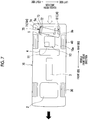
- FIG. 7 is a view schematically illustrating a fuel cell vehicle 70.
- the vibration-proof mounts 71, 81 are illustrated in a sectional view.
- the first supporting portion RH comprising the vibration-proof mount 71 connects the first end portion 5a of the third hydrogen tank 5 on the right side with the vehicle body 9
- the second supporting portion LH comprising the vibration-proof mount 81 connects the second end portion 5b of the third hydrogen tank 5 on the left side with the vehicle body 9.
- the vibration-proof mount 71 includes a ring member 72 wound around the first end portion 5a of the third hydrogen tank 5 on the right side.
- An outer tube 74 that extends in an upward-downward direction, an arm 73 that connects the ring member 72 with the outer tube 74, a shaft member 75 inserted through the outer tube 74, and an attachment member 76 that supports the shaft member 75 in a non-rotatable manner, is attached to the vehicle body 9, and has a substantially C-shaped section.
- An elastic (e.g., rubber) body 77 that connects an inner peripheral surface of the outer tube 74 with an outer peripheral surface of the shaft member 75 is also provided.
- the vibration-proof mount 81 includes a ring member 82 wound around the second end portion 5b of the third hydrogen tank 5 on the left side, a first plate 84, an arm 83 that connects the ring member 82 and the plate 84 together, a second plate 85 attached to the vehicle body 9, and an elastic (e.g., rubber) body 86 that connects the first plate 84 with the second plate 85.
- the shaft member 75 that extends up and down, and the outer tube 74 that rotates around the shaft member 75 constitute the rotating mechanism that supports the third hydrogen tank 5 in a horizontally rotatable manner with respect to the vehicle body 9 even when the elastic (e.g., rubber) body 77 breaks.
- the third hydrogen tank 5 can be horizontally rotated in the clockwise direction about the right side. Accordingly, the impact during a rear collision can be absorbed by causing the second end portion 5b of the third hydrogen tank 5 on the left side contact the part of the transaxle 10 on the left side. Additionally, exposure of the electric motor 11 (i.e., a high-voltage part) can be reduced or prevented by further limiting the damage of the peripheral part of the electric motor 11 in the transaxle 10.
- Embodiments of the present disclosure are described as applied to fuel cell vehicles 1, 60, 70. However, embodiments of the disclosure may be applied to, for example, a hydrogen car or the like.
- Embodiments of the present disclosure are applied to a case where the electrical device is the transaxle 10. However, embodiments of the present disclosure may be applied to a case where the electrical device is a battery unit, the case of a power control unit, and the case of the fuel cell stack 2. Additionally, embodiments of the present disclosure are applied to a rear collision when the electrical device is disposed at the vehicle rear portion. However, embodiments of the present disclosure are not limited to this case and may be applied to a front collision when the transaxle 10, the battery unit, the power control unit, or the fuel cell stack 2 is disposed at the vehicle front portion.
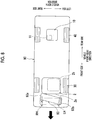
- a hydrogen tank 93 extends in the vehicle width direction
- the hydrogen tank 93 may be horizontally rotated about the first end portion 93b on the left side.
- a second end portion 93a of the hydrogen tank 93 on the right side may be caused to contact the right side of the fuel cell stack 2.
- the first supporting portion RH, the second supporting portion LH, the bracing member 61, and the rotating mechanism are disposed such that the third hydrogen tank 5 is horizontally rotated in the clockwise direction about the first end portion 5a on the right side.
- this configuration is not intended to be limiting, and the first supporting portion RH, the second supporting portion LH, the bracing member 61, and the rotating mechanism may be disposed such that the third hydrogen tank 5 is horizontally rotated in the counterclockwise direction about the second end portion 5b on the left side.
- the first supporting portion RH and the second supporting portion LH comprise the supporting bands.
- embodiments of the disclosure are not limited to the supporting bands as long as the first supporting portion RH does not break and the second supporting portion LH breaks when a collision load equal to or greater than a predetermined value is applied to the third hydrogen tank 5 during a rear collision.
- the first supporting portion RH and the second supporting portion LH may comprise the vibration-proof mounts having the elastic (e.g., rubber) bodies.
- the second hydrogen tank 4 and the third hydrogen tank 5 are coupled together via the bracing member 61.
- a peripheral member which is disposed in front of (inward of) the third hydrogen tank 5 and which has rigidity equal to or greater than the third hydrogen tank 5, is provided, embodiments of the disclosure are not limited to this configuration.
- the peripheral member other than the second hydrogen tank 4 and the third hydrogen tank 5 may be coupled together.
- Embodiments of the disclosure are applied to the fuel cell vehicle 1 including the fuel cell stack 2 that generates electric power using a chemical reaction of hydrogen and oxygen.
- embodiments of the disclosure are not limited to the fuel cell vehicle 1, and aspects of the invention may be applied to a fuel cell vehicle including fuel cells that generate electric power using a chemical reaction of fuel (e.g., gaseous fuel) other than hydrogen and oxidizer gas other than oxygen.
- fuel e.g., gaseous fuel
- the exposure of the high-voltage part at the time of a front collision or a rear collision can be further reduced or prevented.
- embodiments of the disclosure may be desirable when applied to a vehicle in which the electrical device in which the high-voltage part is accommodated in the case is disposed at the vehicle front portion or the vehicle rear portion and a fuel tank is disposed outward of the electrical device in the vehicle front-rear direction, among others.
Abstract
Description
- The present invention relates to a vehicle in which an electrical device having a high-voltage part accommodated in a case, is disposed at a vehicle front portion or a vehicle rear portion.
- In the related art, in vehicles, such as automobiles, various electrical devices having a high-voltage part accommodated in a case are mounted. The various electrical devices include, for example, a battery unit in which a battery serving as a cell is accommodated in a battery case, a power control unit in which a converter or an inverter is accommodated in the case, a fuel cell in which a cell stack is accommodated in the case, and a motor drive unit in which a motor serving as a driving source is accommodated in the case.
- Additionally, in the vehicles, such as automobiles, various fuel tanks in which fuel gas is stored are also mounted. The various fuel tanks include, for example, a tank that stores compressed natural gas in a natural gas vehicle, a tank that stores hydrogen gas in a hydrogen car, and a tank that stores the fuel gas to be supplied to a fuel cell in a fuel cell vehicle.
- In this way, regarding positional relationships between the above-described electrical devices and the above-described fuel tanks, various layouts have been suggested in the related art.
- For example, International Publication
WO2015/185184 (particularlyFIG. 4 ) discloses a fuel cell vehicle in which a motor drive unit is disposed at a vehicle rear portion so as to extend over rear wheel vehicle axles. Two fuel tanks are disposed in front of and behind the motor drive unit, respectively, such that their longitudinal directions are oriented along a vehicle width direction (i.e., perpendicular to a vehicle longitudinal direction). - In fuel cell vehicles in which a fuel tank is disposed rearward of the motor drive unit as in International Publication
WO2015/185184 , at the time of a rear collision, a collision load can be received by the fuel tank, which generally comprises a high-strength component, before being received by the motor drive unit. However, there is a possibility that the motor drive unit may be damaged because the fuel tank is pushed forward due to the collision and may impact the motor drive unit. - When a case is damaged in this way, a high-voltage part (for example, a motor, a terminal portion, or the like) within the motor drive unit that was originally protected with a coating or a cover in order to prevent an electric shock or the like may be peeled off (exposes). A state where the high-voltage part can be touched may occur. In addition, there is a possibility that the exposed high-voltage part may be damaged by contacting a peripheral component.
- The exposure of the high-voltage part as described above is not limited to the layout disclosed in International Publication
WO2015/185184 , and may occur, for example, even during a front collision in a fuel cell vehicle in which a fuel tank is disposed in front of the motor drive unit provided in the vehicle front portion. Additionally, the above described exposure is not limited to the fuel cell vehicle, and is also applicable to, for example, a front collision (or a rear collision) in other vehicles in which fuel tanks are disposed in front of (or behind) an electrical device, such as a battery unit, which is provided in the vehicle front portion (or vehicle rear portion). - The invention provides a technique for further reducing the exposure of a high-voltage part following a front collision or a rear collision, in a vehicle having an electrical device in which the high-voltage part is accommodated in a case is disposed at a vehicle front portion or a vehicle rear portion and a fuel tank is disposed outward of the electrical device in a vehicle front-rear direction.
- In the vehicle according to aspects of the invention, displacement of the fuel tank during a front collision or a rear collision is controlled so that the fuel tank does not contact a peripheral part of the high-voltage part in the electrical device.
- Aspects of the invention relate to a vehicle including an electrical device in which a high-voltage part is accommodated in a case, and a fuel tank in which fuel (e.g., gaseous fuel) is stored. The electrical device is disposed at a vehicle front portion or a vehicle rear portion. The case has a first side end in a vehicle width direction and a second side end opposite to the first side end. The fuel tank is disposed outward of the electrical device in a vehicle front-rear direction so as to extend in the vehicle width direction.
- The high-voltage part is disposed near the first side end of the case in the vehicle width direction within the case. The fuel tank has a first end portion in the vehicle width direction and a second end portion opposite to the first end portion. When a collision load equal to or more than a predetermined value is applied to the fuel tank from the outside in the vehicle front-rear direction, the fuel tank is horizontally rotated around the first end portion of the fuel tank in the vehicle width direction, and the second end portion of the fuel tank in the vehicle width direction is configured to contact the second side end of the electrical device in the vehicle width direction.
- In aspects of the invention, the expression "outward in a vehicle front-rear direction" refers to a position toward a front side or a rear side relative to the given positional reference, while a position toward a vehicle central portion in the vehicle front-rear direction relative to the given positional reference is defined as "inside". Therefore, according to aspects of the invention, the expression "outward of the electrical device in the vehicle front-rear direction" refers to the front side in the vehicle front-rear direction when the electrical device is disposed at the vehicle front portion, and refers to the rear side in the vehicle front-rear direction when the electrical device is disposed at the vehicle rear portion.
- According to aspects of the invention, the expression "horizontally rotated" means rotation around a vertical axis, and means that, for example, the horizontally rotated fuel tank rotates in a clockwise or counterclockwise direction in a plan view.
- According to aspects of the invention, during a front collision or a rear collision, the fuel tank, which is generally made of a high-strength component, receives a collision load before the electrical device. Therefore, exposure of the high-voltage part can be reduced by further restraining the electrical device from being damaged due to a relatively large collision load in the early stages of a collision.
- Additionally, when a collision load equal to or greater than a predetermined value is applied to the fuel tank from the outside in the vehicle front-rear direction, the fuel tank is configured to be horizontally rotated with the first end portion of the fuel tank in the vehicle width direction forming the axis of rotation. Therefore, the second end portion of the horizontally rotated fuel tank in the vehicle width direction contacts the second side end of the electrical device in the vehicle width direction, and thereby impact is absorbed. Here, the high-voltage part is disposed near the first side end of the case in the vehicle width direction within the case. Therefore, exposure of the high-voltage part can be further limited or reduced even when the second side end of the electrical device (for example, the case) in the vehicle width direction is damaged.
- In other words, according to aspects of the invention, when a collision load equal to or greater than a predetermined value is applied to the fuel tank, the fuel tank is horizontally rotated about the end portion near the high-voltage part, and the fuel tank is caused to contact a part of the electrical device away from the high-voltage part. Accordingly, at least a peripheral part of the high-voltage part is further restrained from being damaged, and thus the exposure of the high-voltage part is further limited or reduced.
- Next, a configuration example in which the fuel tank is horizontally rotated around the first end portion in the vehicle width direction when a collision load equal to or greater than a predetermined value is applied to the fuel tank from the outside in the vehicle front-rear direction will be described.
- The vehicle according aspects of the invention may further include a first supporting portion and a second supporting portion respectively provided at the first end portion and the second end portion of the fuel tank in the vehicle width direction. The first supporting portion and the second supporting portion may be configured to support the fuel tank with respect to a vehicle body while allowing displacement of the fuel tank. The first supporting portion that supports the first end portion of the fuel tank in the vehicle width direction may be stronger (i.e., harder to break) than the second supporting portion that supports the second end portion of the fuel tank in the vehicle width direction, with respect to a collision load.
- According to aspects of the invention, the expression "supporting the fuel tank with respect to the vehicle body while allowing displacement of the fuel tank" means a flexible supporting aspect in which the fuel tank is not rigidly fixed to the vehicle body, and for example, a certain amount of displacement in the vehicle front-rear direction, for example, as a result of mounting by suspended support by supporting bands, or elastic support by vibration-proof mounts having elastic (e.g., from rubber) bodies, is allowed.
- According to the aspect of the invention, the first supporting portion is configured to be stronger (i.e., harder to break) than the second supporting portion when acted upon by a collision load. Therefore, even when a collision load equal to or greater than a predetermined value is applied to the fuel tank and the second supporting portion breaks, the first supporting portion that does not break can support the first end portion of the fuel tank in the vehicle width direction while allowing displacement of the fuel tank. Accordingly, the second end portion of the fuel tank in the vehicle width direction can be made to contact a part located away from the high-voltage part in the electrical device by horizontally rotating the fuel tank about the first end portion.
- The vehicle according aspects of the invention may further include a pair of rear side members extending in a vehicle front-rear direction at both end portions of the vehicle in the vehicle width direction; and a pair of brackets connected to the rear side members, respectively. The first supporting portion and the second supporting portion may be supporting bands, each supporting band having an upper end coupled to a corresponding bracket out of the brackets and a lower end coupled to the fuel tank.
- The vehicle according to aspects of the invention may further include a bracing member that couples the first end portion of the fuel tank in the vehicle width direction and a peripheral component disposed inward of the fuel tank in the vehicle front-rear direction together.
- According to aspects of the invention, even when a collision load equal to or greater than a predetermined value is applied to the fuel tank, and for example, both the first supporting portion and the second supporting portion that support the first end portion and the second end portion of the fuel tank in the vehicle width direction, respectively, break, the first end portion of the fuel tank in the vehicle width direction is not displaced because the bracing member functions as a stopper, whereas the second end portion of the fuel tank in the vehicle width direction that is a free end is displaced inward in the vehicle front-rear direction. Accordingly, the fuel tank can be horizontally rotated around the first end portion in the vehicle width direction when a collision load equal to or greater than a predetermined value is applied to the fuel tank from the outside in the vehicle front-rear direction.
- The vehicle according to aspects of the invention may further include a supporting unit that supports the first end portion of the fuel tank in the vehicle width direction with respect to a vehicle body. The supporting unit may have a rotating mechanism that horizontally rotates the fuel tank around the first end portion of the fuel tank.
- According to aspects of the invention, the fuel tank can be easily horizontally rotated around the first end portion of the fuel tank by the rotating mechanism when a collision load equal to or greater than a predetermined value is applied to the fuel tank from the outside in the vehicle front-rear direction.
- In the vehicle according to aspects of the invention, the rotating mechanism of the supporting unit may include a ring member attached to the first end portion of the fuel tank; an outer tube extending in an upward-downward direction of the vehicle; an arm connecting the ring member and the outer tube together; a shaft member inserted through the outer tube; an attachment member that supports the shaft member in a non-rotatable manner and is attached to the vehicle body; and an elastic (e.g., rubber) body that connects an inner peripheral surface of the outer tube and an outer peripheral surface of the shaft member together.
- In the vehicle according to aspects of the invention, the electrical device may be at least one of a motor drive unit in which a motor serving as a driving source and a mechanism for transmitting the driving force of the motor to a vehicle axle are accommodated in a case, a battery unit, a power control unit for motor control, and a fuel cell.
- When the electrical device is the motor drive unit, for example, the motor corresponds to the high-voltage part. Additionally, when the electrical device is the battery unit, for example, a battery corresponds to the high-voltage part, and a battery case corresponds to the case. Moreover, when the electrical device is the power control unit, for example, a converter or an inverter corresponds to the high-voltage part. Additionally, when the electrical device is the fuel cell, for example, a cell stack corresponds to the high-voltage part.
- As described above, according to the vehicle related to aspects of the invention, exposure of the high-voltage part during and after a front collision or a rear collision can be limited or even reduced.
- Features, advantages, and technical and industrial significance of exemplary embodiments of the invention will be described below with reference to the accompanying drawings, in which like numerals denote like elements, and wherein:
-
FIG. 1 is a view schematically illustrating a fuel cell vehicle related toEmbodiment 1 of the invention; -
FIG. 2 is a skeleton view describing a schematic configuration of a transaxle; -
FIG. 3A is a view schematically illustrating a supporting structure of a hydrogen tank; -
FIG. 3B is a view schematically illustrating a supporting structure of the hydrogen tank; -
FIG. 3C is a view schematically illustrating a supporting structure of the hydrogen tank; -
FIG. 3D is a view schematically illustrating a supporting structure of the hydrogen tank; -
FIG. 4 is a view schematically illustrating the displacement of the hydrogen tank at the time of a rear collision; -
FIG. 5 is a view schematically illustrating a fuel cell vehicle related toEmbodiment 2; -
FIG. 6 is a view schematically illustrating a supporting structure of a hydrogen tank related toEmbodiment 3; -
FIG. 7 is a view schematically illustrating a fuel cell vehicle related toEmbodiment 3; and -
FIG. 8 is a view schematically illustrating the appearance of a vehicle related to another embodiment at the time of a front collision. - Hereinafter, embodiments for carrying out the invention will be described with reference to the drawings. Black arrows of
FIG. 1 ,FIG. 4 , andFIGS. 5 ,7 , and8 indicate a vehicle front. - Throughout the disclosure, unless otherwise specified, references to "right" and "left" sides shall be interpreted to be in reference to the right and left sides of the vehicle in which embodiments of the present disclosure are implemented (i.e., along a lateral axis of the vehicle in a vehicle width direction).
- Further, throughout the disclosure, unless otherwise specified, references to "front" and "rear" sides shall be interpreted to be in reference to the front and rear sides of the vehicle in which embodiments of the present disclosure are implemented (i.e., along a longitudinal axis of the vehicle in a vehicle front-rear direction).
-
FIG. 1 is a schematic view illustrating afuel cell vehicle 1 related to the present embodiment. Thefuel cell vehicle 1 is a rear wheel drive fuel cell vehicle, and as illustrated inFIG. 1 , thefuel cell vehicle 1 includes afuel cell stack 2 disposed at avehicle front portion 1a, first tothird hydrogen tanks fuel cell stack 2, atransaxle 10 disposed at a vehiclerear portion 1b,front wheels 30 serving as driven wheels, andrear wheels 40 serving as driving wheels. - The fuel cell stack (fuel cell) 2 is accommodated within an accommodating chamber that is partitioned from a vehicle cabin by a dash panel (not illustrated) and provided at the
vehicle front portion 1a. Thefuel cell stack 2 is a power generation device that generates electrical energy that drives thefuel cell vehicle 1 using a chemical reaction of the hydrogen supplied from the first tothird hydrogen tanks fuel cell stack 2 is formed by stacking a plurality of cells in which an electrode complex obtained by coating both surfaces of a solid polymer electrolyte membrane with a hydrogen electrode catalyst and an oxygen electrode catalyst, respectively, is sandwiched in between separators. - The
fuel cell stack 2 is electrically connected to an electric motor 11 (to be described below) via a DC/DC converter (not illustrated) and an inverter (not illustrated). Accordingly, after the voltage from thefuel cell stack 2 is increased (i.e., stepped up) by the DC/DC converter, a direct current from the DC/DC converter is changed into an alternating current by the inverter, and is supplied to theelectric motor 11. - Generally, in order to extend the range of the fuel cell vehicle (i.e., the maximum distance at which the fuel cell vehicle can travel on a single refueling or the like), there is a need for loading more fuel (e.g., gaseous fuel) into the fuel cell vehicle. However, when relatively large fuel tanks are mounted, effective use of vehicle space is hindered. For this reason, in the
fuel cell vehicle 1 of the present embodiment, three relatively small hydrogen tanks are mounted in three separate locations. Specifically, thefuel cell vehicle 1 includes afirst hydrogen tank 3 disposed so as to extend at a vehicle central portion in a vehicle front-rear direction, asecond hydrogen tank 4 disposed in front of (inward of) thetransaxle 10 so as to extend in a vehicle width direction, and athird hydrogen tank 5 disposed behind (outward of) thetransaxle 10 so as to extend in the vehicle width direction. The first tothird hydrogen tanks third hydrogen tanks fuel cell stack 2. - The first to
third hydrogen tanks second hydrogen tanks third hydrogen tanks third hydrogen tank 5 has afirst end portion 5a on the right side and asecond end portion 5b on the left side, and thefirst end portion 5a and thesecond end portion 5b are respectively supported by a first supporting portion RH and a second supporting portion LH with respect to the vehicle body. -
FIG. 2 is a skeleton view describing a schematic configuration of thetransaxle 10. As illustrated inFIG. 2 , the transaxle (motor drive unit) 10 includes theelectric motor 11 serving as a driving source, a firstreduction gear pair reduction gear pair differential gear mechanism 25. Thetransaxle 10 includes acase 10a made of die cast aluminum. Thecase 10a accommodating theelectric motor 11, the firstreduction gear pair reduction gear pair differential gear mechanism 25. As illustrated inFIG. 1 , thetransaxle 10 is disposed at the vehiclerear portion 1b at least partially overlap rearwheel vehicle axles 40a, and is configured to transmit a driving force generated in theelectric motor 11 to the rearwheel vehicle axles 40a via the firstreduction gear pair reduction gear pair differential gear mechanism 25. - The
electric motor 11 has arotor shaft 12, and astator 13 fixed to thetransaxle case 10a, so as to surround an outer periphery of therotor shaft 12. Therotor shaft 12 is rotatably supported by thetransaxle case 10a via a pair ofbearings rotor shaft 12. Anoutput shaft 16 connected to therotor shaft 12 is rotatably supported by thetransaxle case 10a via a pair ofbearings output shaft 16, and rotates integrally with therotor shaft 12. In addition, theelectric motor 11 is disposed at a position near the front side and near a first side end on the right side , as illustrated by a dashed line inFIG. 1 , within thetransaxle case 10a. - The first
reduction gear pair counter drive gear 19 that is provided at a first end portion (an end portion opposite to the electric motor 11) of theoutput shaft 16, and a larger-diameter counter drivengear 21 that is provided at a first end portion (an end portion opposite to the electric motor 11) of acounter shaft 20 parallel to theoutput shaft 16 and meshes with thecounter drive gear 19. In addition, thecounter shaft 20 is rotatably supported by thetransaxle case 10a via a pair ofbearings 23, 24 mounted on both ends of thecounter shaft 20. - The second
reduction gear pair final drive gear 22 that is provided at the second end portion (an end portion on theelectric motor 11 side) of thecounter shaft 20, and a larger-diameter final drivengear 26 that is integrally fixed to an outer peripheral portion of adifferential case 25a and meshes with thefinal drive gear 22. Thedifferential case 25a and the final drivengear 26 integrally fixed to thedifferential case 25a are rotatably supported by thetransaxle case 10a via a pair ofbearings differential case 25a in an axial direction. - The
differential gear mechanism 25 has thedifferential case 25a, and a so-called bevel geartype differential mechanism 25b accommodated within thedifferential case 25a, and is configured to transmit a driving force to a pair of rearwheel vehicle axles 40a while allowing a rotating speed difference. - In the
fuel cell vehicle 1 configured as described above, thefuel cell stack 2 generates electric power by hydrogen being supplied from the first tothird hydrogen tanks electric motor 11 is driven by the electrical energy from thefuel cell stack 2, and the driving force generated in theelectric motor 11 is transmitted to thedifferential gear mechanism 25 via the firstreduction gear pair reduction gear pair differential gear mechanism 25 via the rearwheel vehicle axles 40a to therear wheels 40. - Meanwhile, in a fuel cell vehicle in which a hydrogen tank is disposed on the rear side of the transaxle , a collision load can be received by the hydrogen tank comprising a high-strength component before being received by the transaxle during a rear collision. However, it is possible that the transaxle (for example, the transaxle case) may be damaged because the hydrogen tank that has moved to the front side due to the collision contacts the transaxle.
- In this way, for example, when the transaxle case is damaged, it is possible that a high-voltage part (for example, an electric motor or the like) within the transaxle that should originally be protected with a coating or a cover in order to restrain an electric shock or the like is exposed. A state where the high-voltage part can be touched may occur, or there is a case where the exposed high-voltage part may be damaged by contacting a peripheral component.
- In the present embodiment, the displacement of the
third hydrogen tank 5 during a rear collision is controlled so that thethird hydrogen tank 5 does not contact a peripheral part of theelectric motor 11 in thetransaxle 10. Specifically, in thefuel cell vehicle 1 of the present embodiment, when theelectric motor 11 is disposed near the first side end on the right side within thetransaxle case 10a, and a collision load equal to or more than a predetermined value is applied from the rear side (outside), thethird hydrogen tank 5 is horizontally rotated about thefirst end portion 5a on the right side , and thesecond end portion 5b of thethird hydrogen tank 5 on the left side is caused to contact a second side end of thetransaxle 10 on the left side. - That is, in the present embodiment, when a collision load equal to or greater than a predetermined value is applied from the rear side (outside), the
third hydrogen tank 5 is horizontally rotated about theend portion 5a near the electric motor 11 (i.e., a high-voltage part), and thethird hydrogen tank 5 is caused to contact a part of thetransaxle 10 located away from theelectric motor 11. Accordingly, at least the peripheral part of theelectric motor 11 is further restrained from being damaged, and thus, theelectric motor 11 is not exposed. - Hereinafter, an example in which the
third hydrogen tank 5 is horizontally rotated about thefirst end portion 5a on the right side when a collision load equal to or greater than a predetermined value is applied from the rear side will be described. -
FIG. 3A is a view schematically illustrating a supporting structure of thethird hydrogen tank 5. As illustrated inFIG. 3A , thethird hydrogen tank 5 is connected tobrackets 6 on the right side and the left side via the first supporting portion RH and the second supporting portion LH on the rear side of thetransaxle 10. Thebrackets 6 are respectively connected to a pair of rear side members (vehicle body) 8 extending in the vehicle front-rear direction at the first end portion and thesecond end portion third hydrogen tank 5 is supported by thevehicle body 8 via the first supporting portion RH, the second supporting portion LH, and thebrackets 6 on the rear side of thetransaxle 10. - The first supporting portion RH, which supports the
first end portion 5a of thethird hydrogen tank 5 on the right side , comprises a supporting band connected to thebracket 6 on the right side. Additionally, the second supporting portion LH, which supports thesecond end portion 5b of thethird hydrogen tank 5 on the left side, also comprises a supporting band connected to thebracket 6 on the left side. As described above, the suspended supporting structure by the supporting bands is adopted. Accordingly, even when thethird hydrogen tank 5 is slightly deformed (expanded or contracted) due to heat or the like, deformation of thethird hydrogen tank 5 can be compensated for by the supporting bands. Thus, it is possible to stably support thethird hydrogen tank 5. Additionally, by adopting the suspended supporting structure by the supporting bands, it is possible to allow a certain amount of displacement of thethird hydrogen tank 5 accompanying the vibration of the vehicle body, unlike when thethird hydrogen tank 5 is firmly fixed to the vehicle body with bolts (not illustrated) or the like. - In this way, the first supporting portion RH is configured to be stronger (i.e., harder to break) than the second supporting portion LH with respect to a collision load. In more detail, when a collision load equal to or greater than a predetermined value is applied to the
third hydrogen tank 5 during a rear collision, the first supporting portion RH should not break, whereas the second supporting portion LH is configured to break and thethird hydrogen tank 5 is supported solely by the first supporting portion RH. Accordingly, thethird hydrogen tank 5 is horizontally rotated about thefirst end portion 5a on the right side. - As described above, the first supporting portion RH being stronger than the second supporting portion LH with respect to a collision load can be realized by forming the supporting band 51 of the first supporting portion RH and the supporting
band 52 of the second supporting portion LH with different materials, as illustrated inFIG. 3B , for example, when the shapes or sizes of the supporting band of the first supporting portion RH and the supporting band of the second supporting portion LH are the same.FIG. 3B to FIG. 3D illustrate that the materials differ by using different hatching. - More specifically, the first supporting portion RH can be made stronger than the second supporting portion LH with respect to a collision load by forming the supporting band 51 of the first supporting portion RH with a material having a yield strength higher than the yield strength of the supporting
band 52 of the second supporting portion LH. In the above-described case, for example, a collision load (predetermined value), which displaces thethird hydrogen tank 5 to the front side as thethird hydrogen tank 5contacts transaxle 10, may be assumed based on experiment, simulation, or the like. Then, a material having a yield strength such that the supporting band 51 does not break may be selected based on the assumed collision load, the cross-sectional area of the supportingbands 51, 52, and the like, and a material having a yield strength such that the supportingband 52 breaks under the load may be selected for the supportingband 52. - Additionally, for example, when supporting bands having the same material (yield strength) are used as the first supporting portion RH and the second supporting portion LH, the first supporting portion RH can be made stronger than the second supporting portion LH with respect to a collision load by forming the first supporting portion RH with a supporting
band 53 wider (having a larger cross-sectional area) than a supportingband 54 of the second supporting portion LH, as illustrated inFIG. 3C . - Moreover, for example, when supporting
bands 55 having the same shape, size, and material (yield strength) are used as the first supporting portion RH and the second supporting portion LH, the first supporting portion RH can be made stronger than the second supporting portion LH with respect to a collision load by forming the first supporting portion RH with additional (e.g., two or more) supportingbands 55, and forming the second supporting portion LH with only one supportingband 55, as illustrated inFIG. 3D . - By virtue of the above configuration, during a rear collision as indicated by a dashed line arrow of
FIG. 4 , thethird hydrogen tank 5 made of the high-strength component receives a collision load before thetransaxle 10. Therefore, exposure of the electric motor 11 (i.e., a high-voltage part) can be reduced or prevented by further limiting damage to thetransaxle 10 due to a relatively large collision load during early stages of a collision. - Moreover, when a collision load equal to or greater than a predetermined value is applied to the
third hydrogen tank 5, the supportingbands third hydrogen tank 5 is released (refer to mark X ofFIG. 4 ). However, because the first supporting portion RH, in which the supportingbands 51, 53, 55(RH) are left without breaking, supports thefirst end portion 5a on the right side of thethird hydrogen tank 5, while allowing displacement of the fuel tank, as indicated by a white arrow ofFIG. 4 , thethird hydrogen tank 5 is horizontally rotated in the clockwise direction about thefirst end portion 5a on the right side. As described above, when thethird hydrogen tank 5 is horizontally rotated in the clockwise direction about thefirst end portion 5a on the right side, thesecond end portion 5b of thethird hydrogen tank 5 on the left side contacts a part of thetransaxle 10 on the left side, and the impact during a rear collision can be absorbed. Here, since theelectric motor 11 is disposed near the right side within thetransaxle case 10a, even when a part of thetransaxle case 10a on the left side is damaged, exposure of the electric motor 11 (i.e., a high-voltage part) can be reduced or limited. - In relation to the claims, the
transaxle 10 in which theelectric motor 11 serving as a high-voltage part and a mechanism for transmitting the driving force of theelectric motor 11 to the vehicle axles are accommodated in thetransaxle case 10a is an example of an "electrical device in which a high-voltage part is accommodated in the case". - The present embodiment is different from
Embodiment 1 in that thesecond hydrogen tank 4 and thethird hydrogen tank 5 are coupled together via a bracing member. Hereinafter, different points fromEmbodiment 1 will mainly be described. -
FIG. 5 is a view schematically illustrating afuel cell vehicle 60 related to the present embodiment. As illustrated inFIG. 5 , thefirst end portion 5a of thethird hydrogen tank 5 on the right side is coupled via a bracingmember 61 to anend portion 4a, on the right side , of the second hydrogen tank (peripheral component) 4 disposed in front of (inward of) thethird hydrogen tank 5. - When a collision load equal to or greater than a predetermined value is applied to the
third hydrogen tank 5 during a rear collision, bracingmember 61 may transmit at least a portion of the collision load tosecond hydrogen tank 4 without buckling. With this in mind, the shape of the bracingmember 61 is not particularly limited, and for example, may be a rod shape or a hollow box shape such that bracingmember 61 has sufficient strength such that the collision load can be transmitted to thesecond hydrogen tank 4 without buckling. - Additionally, aspects of coupling between the bracing
member 61, and thesecond hydrogen tank 4 and thethird hydrogen tank 5 are not particularly limited when the bracingmember 61 functions as a "barrier" between thesecond hydrogen tank 4 and thethird hydrogen tank 5 during a rear collision and the horizontal rotation of thethird hydrogen tank 5 is not hindered. For example, as illustrated inFIG. 5 , a front end portion of the bracingmember 61 may be firmly fixed to aring member 62 wound around theend portion 4a of thesecond hydrogen tank 4 on the right side , and rear end portion of the bracingmember 61 may be applied to thefirst end portion 5a of thethird hydrogen tank 5 on the right side , or thefirst end portion 5a of thethird hydrogen tank 5 on the right side , and the rear end portion of the bracingmember 61 may also be connected together via a hinge (not illustrated). - Moreover, the first supporting portion RH and the second supporting portion LH that support both end portions of the
third hydrogen tank 5, respectively, may comprise, for example, vibration-proof mounts having supporting bands or elastic (e.g., rubber) bodies. In such a case, when a collision load equal to or greater than a predetermined value is applied to thethird hydrogen tank 5 during a rear collision, only the second supporting portion LH that supports thesecond end portion 5b of thethird hydrogen tank 5 on the left side may be broken, or both the first supporting portion RH and the second supporting portion LH that support the first end portion and thesecond end portion third hydrogen tank 5 may be broken. - By virtue of this configuration, during a rear collision, as indicated by a dashed line arrow of
FIG. 5 , for example, even when both the first supporting portion RH and the second supporting portion LH break as illustrated by marks X ofFIG. 5 , thefirst end portion 5a of thethird hydrogen tank 5 on the right side is not displaced because the bracingmember 61 functions as a barrier, whereas thesecond end portion 5b of thethird hydrogen tank 5 on the left side , which is a free end, is displaced to the front side. Accordingly, as indicated by a white arrow ofFIG. 5 , the impact during a rear collision can be absorbed by horizontally rotating thethird hydrogen tank 5 in the clockwise direction about thefirst end portion 5a on the right side to cause thesecond end portion 5b of thethird hydrogen tank 5 on the left side contact the part of thetransaxle 10 on the left side. Additionally, exposure of the electric motor 11 (i.e., a high-voltage part) can be reduced or prevented by further limiting the damage of the peripheral part of theelectric motor 11 in thetransaxle 10. - In relation to the claims, the
second hydrogen tank 4 disposed on the front side of thetransaxle 10 is an example of "the peripheral component of the electrical device". - The present embodiment is different from
Embodiment 1 in that the first supporting portion RH includes a rotating mechanism. Hereinafter, different points fromEmbodiment 1 will mainly be described. -
FIG. 6 is a view schematically illustrating a supporting structure of thethird hydrogen tank 5, andFIG. 7 is a view schematically illustrating afuel cell vehicle 70. In addition, inFIG. 6 , for the convenience of description, the vibration-proof mounts 71, 81 are illustrated in a sectional view. - In the
fuel cell vehicle 70, as illustrated inFIG. 6 , the first supporting portion RH comprising the vibration-proof mount 71 connects thefirst end portion 5a of thethird hydrogen tank 5 on the right side with thevehicle body 9, and the second supporting portion LH comprising the vibration-proof mount 81 connects thesecond end portion 5b of thethird hydrogen tank 5 on the left side with thevehicle body 9. - The vibration-
proof mount 71 includes aring member 72 wound around thefirst end portion 5a of thethird hydrogen tank 5 on the right side. Anouter tube 74 that extends in an upward-downward direction, anarm 73 that connects thering member 72 with theouter tube 74, ashaft member 75 inserted through theouter tube 74, and anattachment member 76 that supports theshaft member 75 in a non-rotatable manner, is attached to thevehicle body 9, and has a substantially C-shaped section. An elastic (e.g., rubber)body 77 that connects an inner peripheral surface of theouter tube 74 with an outer peripheral surface of theshaft member 75 is also provided. - Meanwhile, the vibration-
proof mount 81 includes aring member 82 wound around thesecond end portion 5b of thethird hydrogen tank 5 on the left side, afirst plate 84, anarm 83 that connects thering member 82 and theplate 84 together, asecond plate 85 attached to thevehicle body 9, and an elastic (e.g., rubber)body 86 that connects thefirst plate 84 with thesecond plate 85. - In this way, effective sectional area and tear strength with respect to a tensile load and a shearing load, respectively, are set such that the elastic (e.g., rubber)
bodies third hydrogen tank 5 during a rear collision. - By virtue of the above configuration, when a collision load equal to or greater than a predetermined value is applied to the
transaxle 10 during a rear collision as indicated by a dashed line arrow ofFIG. 7 , the elastic (e.g., rubber)body 86 breaks, and the connection between the second supporting portion LH and thethird hydrogen tank 5 is released, as illustrated by mark X ofFIG. 7 . Meanwhile, in the first supporting portion RH, even when the elastic (e.g., rubber)body 77 breaks, a structure is left in which theouter tube 74 connected to thethird hydrogen tank 5 via thering member 72 and thearm 73 is rotatable about theshaft member 75 attached to thevehicle body 9 side in a non-rotatable manner. That is, in the first supporting portion RH, theshaft member 75 that extends up and down, and theouter tube 74 that rotates around theshaft member 75 constitute the rotating mechanism that supports thethird hydrogen tank 5 in a horizontally rotatable manner with respect to thevehicle body 9 even when the elastic (e.g., rubber)body 77 breaks. Thus, thethird hydrogen tank 5 can be horizontally rotated in the clockwise direction about the right side. Accordingly, the impact during a rear collision can be absorbed by causing thesecond end portion 5b of thethird hydrogen tank 5 on the left side contact the part of thetransaxle 10 on the left side. Additionally, exposure of the electric motor 11 (i.e., a high-voltage part) can be reduced or prevented by further limiting the damage of the peripheral part of theelectric motor 11 in thetransaxle 10. - The invention is not limited to the embodiments described, and can be carried out in other various ways without deviating from the scope of the claims.
- Embodiments of the present disclosure are described as applied to
fuel cell vehicles - Embodiments of the present disclosure are applied to a case where the electrical device is the
transaxle 10. However, embodiments of the present disclosure may be applied to a case where the electrical device is a battery unit, the case of a power control unit, and the case of thefuel cell stack 2. Additionally, embodiments of the present disclosure are applied to a rear collision when the electrical device is disposed at the vehicle rear portion. However, embodiments of the present disclosure are not limited to this case and may be applied to a front collision when thetransaxle 10, the battery unit, the power control unit, or thefuel cell stack 2 is disposed at the vehicle front portion. - For example, as illustrated in
FIG. 8 , in afuel cell vehicle 90 in which thefuel cell stack 2 is disposed at the vehicle front portion and is disposed on the front side of thefuel cell stack 2 such that ahydrogen tank 93 extends in the vehicle width direction, when a cell stack (high-voltage part) 2b is disposed on the left side within acase 2a and a collision load equal to or greater than a predetermined value is applied from the front side , thehydrogen tank 93 may be horizontally rotated about thefirst end portion 93b on the left side. Thereby, asecond end portion 93a of thehydrogen tank 93 on the right side may be caused to contact the right side of thefuel cell stack 2. - In the respective embodiments, the first supporting portion RH, the second supporting portion LH, the bracing
member 61, and the rotating mechanism are disposed such that thethird hydrogen tank 5 is horizontally rotated in the clockwise direction about thefirst end portion 5a on the right side. However, this configuration is not intended to be limiting, and the first supporting portion RH, the second supporting portion LH, the bracingmember 61, and the rotating mechanism may be disposed such that thethird hydrogen tank 5 is horizontally rotated in the counterclockwise direction about thesecond end portion 5b on the left side. - In
Embodiment 1, the first supporting portion RH and the second supporting portion LH comprise the supporting bands. However, embodiments of the disclosure are not limited to the supporting bands as long as the first supporting portion RH does not break and the second supporting portion LH breaks when a collision load equal to or greater than a predetermined value is applied to thethird hydrogen tank 5 during a rear collision. For example, the first supporting portion RH and the second supporting portion LH may comprise the vibration-proof mounts having the elastic (e.g., rubber) bodies. - In
Embodiment 2, thesecond hydrogen tank 4 and thethird hydrogen tank 5 are coupled together via the bracingmember 61. However, as long as a peripheral member, which is disposed in front of (inward of) thethird hydrogen tank 5 and which has rigidity equal to or greater than thethird hydrogen tank 5, is provided, embodiments of the disclosure are not limited to this configuration. For example, the peripheral member other than thesecond hydrogen tank 4 and thethird hydrogen tank 5 may be coupled together. - Embodiments of the disclosure are applied to the
fuel cell vehicle 1 including thefuel cell stack 2 that generates electric power using a chemical reaction of hydrogen and oxygen. However, embodiments of the disclosure are not limited to thefuel cell vehicle 1, and aspects of the invention may be applied to a fuel cell vehicle including fuel cells that generate electric power using a chemical reaction of fuel (e.g., gaseous fuel) other than hydrogen and oxidizer gas other than oxygen. - As described above, the embodiments are merely illustrative in all respects, and should not be interpreted restrictively. Moreover, all modifications or alternations belonging to the equivalent scope of the claims are within the scope of the invention.
- According to aspects of the invention, the exposure of the high-voltage part at the time of a front collision or a rear collision can be further reduced or prevented. Thus, embodiments of the disclosure may be desirable when applied to a vehicle in which the electrical device in which the high-voltage part is accommodated in the case is disposed at the vehicle front portion or the vehicle rear portion and a fuel tank is disposed outward of the electrical device in the vehicle front-rear direction, among others.
Claims (12)
- A vehicle (1, 60, 70, 90) comprising:an electrical device (10, 2) including a high-voltage part (11, 2b) accommodated in a case (10a, 2a), the electrical device (10, 2) being disposed at a vehicle front portion or a vehicle rear portion, and the case (10a, 2a) having a first side end in a vehicle width direction and a second side end opposite to the first side end; anda fuel tank (5, 93) in which fuel gas is stored, the fuel tank (5, 93) being disposed outward of the electrical device (10, 2) in a vehicle front-rear direction, the fuel tank (5, 93) extending in the vehicle width direction, wherein:the high-voltage part (11, 2b) is disposed within the case (10a, 2a) near the first side end of the case (10a, 2a) in the vehicle width direction;the fuel tank (5, 93) has a first end portion (5a, 93b) in the vehicle width direction and a second end portion (5b, 93a) opposite to the first end portion (5a, 93b); andwhen a collision load equal to or greater than a predetermined value is applied to the fuel tank from outside in the vehicle front-rear direction, the fuel tank (5, 93) is configured to horizontally rotate about the first end portion (5a, 93b) of the fuel tank (5, 93), and the second end portion (5b, 93a) of the fuel tank (5, 93) is configured to contact the second side end of the electrical device (10, 2).
- The vehicle (1, 60, 70, 90) according to claim 1, further comprising a first supporting portion (RH) and a second supporting portion (LH) respectively provided at the first end portion (5a, 93b) and the second end portion (5b, 93a) of the fuel tank (5, 93), the first supporting portion (RH) and the second supporting portion (LH) being configured to support the fuel tank (5, 93) with respect to a vehicle body while allowing displacement of the fuel tank (5, 93),
wherein the first supporting portion (RH) that supports the first end portion (5a, 93b) of the fuel tank (5, 93) is configured to be stronger than the second supporting portion (LH) that supports the second end portion (5b, 93a) of the fuel tank (5, 93) with respect to the collision load. - The vehicle (1, 60, 70, 90) according to claim 2, further comprising:a pair of rear side members (8) extending in the vehicle front-rear direction at both end portions of the vehicle in the vehicle width direction; anda pair of brackets (6) connected to the rear side members (8), respectively,wherein the first supporting portion (RH) and the second supporting portion (LH) are supporting bands, each supporting band having an upper end coupled to a corresponding bracket of the pair of brackets (6) and a lower end coupled to the fuel tank (5, 93).
- The vehicle (60) according to any one of claims 1 to 3, further comprising:a bracing member (61) that couples the first end portion (5a) of the fuel tank (5) in the vehicle width direction with a peripheral component disposed inward of the fuel tank (5) in the vehicle front-rear direction.
- The vehicle (70) according to any of claim 1 or 2, further comprising:a supporting unit (71) that supports the first end portion (5a) of the fuel tank (5) in the vehicle width direction with respect to a vehicle body,
wherein the supporting unit (71) has a rotating mechanism that horizontally rotates the fuel tank (5) around the first end portion (5a) of the fuel tank (5). - The vehicle (70) according to claim 5, wherein the rotating mechanism of the supporting unit includes
a ring member (72) attached to the first end portion (5a) of the fuel tank (5),
an outer tube (74) extending in an upward-downward direction of the vehicle,
an arm (73) connecting the ring member (72) and the outer tube (74) together,
a shaft member (75) inserted through the outer tube (74),
an attachment member (76) that supports the shaft member (75) in a non-rotatable manner and is attached to the vehicle body (9), and
an elastic body (77) that connects an inner peripheral surface of the outer tube (74) and an outer peripheral surface of the shaft member (75) together. - The vehicle (1, 60, 70, 90) according to any one of claims 1 to 6, wherein the electrical device (10, 2) is at least one of a motor drive unit in which a motor serving as a driving source and a mechanism for transmitting a driving force of the motor to a vehicle axle are accommodated in the case, a battery unit, a power control unit for motor control, and a fuel cell.
- The vehicle (1, 60, 70, 90) according to any one of claims 1-7, wherein the first supporting portion (RH) that supports the first end portion (5a, 93b) of the fuel tank (5, 93) comprises a cross-section of greater surface area than a related cross-section of the second supporting portion (LH) that supports the second end portion (5b, 93a) of the fuel tank (5, 93).
- The vehicle (1, 60, 70, 90) according to any of claims 1-7, wherein the first supporting portion (RH) that supports the first end portion (5a, 93b) of the fuel tank (5, 93) comprises a plurality of supporting bands (55), and the second supporting portion (LH) that supports the second end portion (5b, 93a) of the fuel tank (5, 93) comprises only one supporting band (55).
- The vehicle (1, 60, 70, 90) according to any one of claims 1-7, wherein the first supporting portion (RH) that supports the first end portion (5a, 93b) of the fuel tank (5, 93) comprises a material different than that of the second supporting portion (LH) that supports the second end portion (5b, 93a) of the fuel tank (5, 93).
- The vehicle (1, 60, 70, 90) according to claim 4, wherein the peripheral component is a second fuel tank (4), and wherein the fuel tank (5, 95) and the second fuel tank (4) are optionally fluidly connected.
- The vehicle (70) according to claim 6, wherein the elastic body (77) comprises a rubber compound.
Applications Claiming Priority (1)
| Application Number | Priority Date | Filing Date | Title |
|---|---|---|---|
| JP2017038297A JP6589909B2 (en) | 2017-03-01 | 2017-03-01 | vehicle |
Publications (2)
| Publication Number | Publication Date |
|---|---|
| EP3369600A1 true EP3369600A1 (en) | 2018-09-05 |
| EP3369600B1 EP3369600B1 (en) | 2019-12-04 |
Family
ID=61386754
Family Applications (1)
| Application Number | Title | Priority Date | Filing Date |
|---|---|---|---|
| EP18158761.9A Active EP3369600B1 (en) | 2017-03-01 | 2018-02-27 | Vehicle with pivoting fuel tank in case of crash |
Country Status (4)
| Country | Link |
|---|---|
| US (1) | US10300788B2 (en) |
| EP (1) | EP3369600B1 (en) |
| JP (1) | JP6589909B2 (en) |
| CN (1) | CN108528232B (en) |
Cited By (1)
| Publication number | Priority date | Publication date | Assignee | Title |
|---|---|---|---|---|
| FR3125753A1 (en) * | 2021-07-27 | 2023-02-03 | Faurecia Systemes D'echappement | Device for attaching a tank to a vehicle |
Families Citing this family (13)
| Publication number | Priority date | Publication date | Assignee | Title |
|---|---|---|---|---|
| JP6597653B2 (en) * | 2017-01-19 | 2019-10-30 | トヨタ自動車株式会社 | Fuel cell vehicle |
| JP6589909B2 (en) * | 2017-03-01 | 2019-10-16 | トヨタ自動車株式会社 | vehicle |
| JP6939040B2 (en) * | 2017-04-18 | 2021-09-22 | トヨタ自動車株式会社 | vehicle |
| JP6766745B2 (en) * | 2017-05-11 | 2020-10-14 | トヨタ自動車株式会社 | vehicle |
| US11110785B2 (en) * | 2017-08-02 | 2021-09-07 | Toyota Jidosha Kabushiki Kaisha | Vehicle rear portion structure |
| CN112776580A (en) * | 2017-09-20 | 2021-05-11 | 丰田自动车株式会社 | Electric vehicle |
| JP7056536B2 (en) * | 2018-12-06 | 2022-04-19 | トヨタ自動車株式会社 | Fuel cell vehicle |
| WO2020207581A1 (en) * | 2019-04-10 | 2020-10-15 | Volvo Truck Corporation | A vehicle comprising a battery protection structure |
| KR20210017355A (en) * | 2019-08-08 | 2021-02-17 | 현대자동차주식회사 | Battery and fuel tank arrangement structure of hybrid vehicle |
| DE102019123843A1 (en) * | 2019-09-05 | 2021-03-11 | Bayerische Motoren Werke Aktiengesellschaft | Component arrangement for a crash zone of a motor vehicle |
| FR3104505B1 (en) * | 2019-12-16 | 2021-11-12 | Airbus Operations Sas | VEHICLE EQUIPPED WITH A HYDROGEN TANK CONTAINING AT LEAST ONE ELECTRICAL CONNECTION DEVICE |
| US11325453B2 (en) * | 2019-12-18 | 2022-05-10 | Toyota Motor Engineering & Manufacturing North America, Inc. | Battery mounting bracket for heavy duty vehicle |
| JP2022029621A (en) | 2020-08-05 | 2022-02-18 | 株式会社Subaru | Container holding mechanism of fuel cell vehicle |
Citations (6)
| Publication number | Priority date | Publication date | Assignee | Title |
|---|---|---|---|---|
| WO2005035291A1 (en) * | 2003-10-07 | 2005-04-21 | Toyota Jidosha Kabushiki Kaisha | Fuel tank supporting structure |
| US20080111048A1 (en) * | 2006-11-15 | 2008-05-15 | Jin-Han Jang | Rear impact shock absorbing structure for fuel cell vehicle |
| JP2011042208A (en) * | 2009-08-20 | 2011-03-03 | Toyota Motor Corp | Tank support structure in vehicle |
| EP2439128A1 (en) * | 2009-06-05 | 2012-04-11 | Toyota Jidosha Kabushiki Kaisha | Vehicle |
| EP2441613A1 (en) * | 2009-06-09 | 2012-04-18 | Toyota Jidosha Kabushiki Kaisha | Fuel cell vehicle |
| WO2015185184A1 (en) | 2014-06-07 | 2015-12-10 | Audi Ag | Vehicle having an energy storage means |
Family Cites Families (20)
| Publication number | Priority date | Publication date | Assignee | Title |
|---|---|---|---|---|
| JP2932133B2 (en) * | 1993-03-19 | 1999-08-09 | トヨタ自動車株式会社 | Auxiliary parts arrangement structure for electric vehicles |
| JP2004122972A (en) * | 2002-10-03 | 2004-04-22 | Toyota Motor Corp | Automobile |
| JP4649849B2 (en) * | 2004-03-02 | 2011-03-16 | トヨタ自動車株式会社 | Storage mechanism mounting structure |
| US7066515B2 (en) * | 2004-10-08 | 2006-06-27 | General Motors Corporation | Deformable component carrier |
| JP5141026B2 (en) * | 2006-02-27 | 2013-02-13 | トヨタ自動車株式会社 | In-vehicle structure of power storage pack |
| JP4935112B2 (en) * | 2006-02-28 | 2012-05-23 | トヨタ自動車株式会社 | In-vehicle structure of power storage pack |
| US8932769B2 (en) * | 2009-05-28 | 2015-01-13 | Toyota Jidosha Kabushiki Kaisha | Fuel cell assembly and vehicle |
| US8393426B2 (en) * | 2009-06-25 | 2013-03-12 | Toyota Jidosha Kabushiki Kaisha | Vehicle structure of a hybrid vehicle |
| JP5270702B2 (en) * | 2011-02-14 | 2013-08-21 | トヨタ自動車株式会社 | Vehicle equipment mounting structure |
| JP5803259B2 (en) * | 2011-05-17 | 2015-11-04 | 日産自動車株式会社 | Battery pack structure for electric vehicles |
| JP5375886B2 (en) * | 2011-07-26 | 2013-12-25 | トヨタ自動車株式会社 | Battery protection structure for automobiles |
| US9199550B2 (en) * | 2011-12-05 | 2015-12-01 | Toyota Jidosha Kabushiki Kaisha | Fuel cell vehicle |
| JP6089403B2 (en) * | 2012-01-17 | 2017-03-08 | 日産自動車株式会社 | Battery system element arrangement structure of electric vehicle |
| CN103072468B (en) * | 2013-01-31 | 2016-02-03 | 重庆长安汽车股份有限公司 | A kind of collision energy-absorbing formula fuel cylinder mounting bracket |
| JP2016049862A (en) * | 2014-08-29 | 2016-04-11 | トヨタ自動車株式会社 | Inverter on-vehicle structure |
| JP2016088264A (en) * | 2014-11-04 | 2016-05-23 | トヨタ自動車株式会社 | Vehicle structure |
| JP6597653B2 (en) * | 2017-01-19 | 2019-10-30 | トヨタ自動車株式会社 | Fuel cell vehicle |
| US9963028B1 (en) * | 2017-02-21 | 2018-05-08 | Ford Global Technologies, Llc | Battery support structure for electrified vehicle |
| JP6589909B2 (en) * | 2017-03-01 | 2019-10-16 | トヨタ自動車株式会社 | vehicle |
| JP6939040B2 (en) * | 2017-04-18 | 2021-09-22 | トヨタ自動車株式会社 | vehicle |
-
2017
- 2017-03-01 JP JP2017038297A patent/JP6589909B2/en active Active
-
2018
- 2018-02-27 CN CN201810161778.9A patent/CN108528232B/en active Active
- 2018-02-27 US US15/906,735 patent/US10300788B2/en active Active
- 2018-02-27 EP EP18158761.9A patent/EP3369600B1/en active Active
Patent Citations (6)
| Publication number | Priority date | Publication date | Assignee | Title |
|---|---|---|---|---|
| WO2005035291A1 (en) * | 2003-10-07 | 2005-04-21 | Toyota Jidosha Kabushiki Kaisha | Fuel tank supporting structure |
| US20080111048A1 (en) * | 2006-11-15 | 2008-05-15 | Jin-Han Jang | Rear impact shock absorbing structure for fuel cell vehicle |
| EP2439128A1 (en) * | 2009-06-05 | 2012-04-11 | Toyota Jidosha Kabushiki Kaisha | Vehicle |
| EP2441613A1 (en) * | 2009-06-09 | 2012-04-18 | Toyota Jidosha Kabushiki Kaisha | Fuel cell vehicle |
| JP2011042208A (en) * | 2009-08-20 | 2011-03-03 | Toyota Motor Corp | Tank support structure in vehicle |
| WO2015185184A1 (en) | 2014-06-07 | 2015-12-10 | Audi Ag | Vehicle having an energy storage means |
Cited By (1)
| Publication number | Priority date | Publication date | Assignee | Title |
|---|---|---|---|---|
| FR3125753A1 (en) * | 2021-07-27 | 2023-02-03 | Faurecia Systemes D'echappement | Device for attaching a tank to a vehicle |
Also Published As
| Publication number | Publication date |
|---|---|
| JP6589909B2 (en) | 2019-10-16 |
| CN108528232B (en) | 2021-02-12 |
| US10300788B2 (en) | 2019-05-28 |
| US20180251023A1 (en) | 2018-09-06 |
| CN108528232A (en) | 2018-09-14 |
| EP3369600B1 (en) | 2019-12-04 |
| JP2018144509A (en) | 2018-09-20 |
Similar Documents
| Publication | Publication Date | Title |
|---|---|---|
| EP3369600B1 (en) | Vehicle with pivoting fuel tank in case of crash | |
| JP7127298B2 (en) | fuel cell vehicle | |
| US10518620B2 (en) | Fuel cell mounting structure | |
| CN106671761B (en) | The carrying structure of fuel cell | |
| JP6468093B2 (en) | Fuel cell vehicle | |
| JP5257718B2 (en) | vehicle | |
| JP5656032B2 (en) | Vehicle rear protection structure | |
| US8573647B2 (en) | Vehicle with traction battery capable of absorbing crash energy | |
| WO2014123040A1 (en) | Structure for securing hydrogen tank in fuel-cell-type industrial vehicle and fuel cell unit | |
| US20210053623A1 (en) | Vehicle front structure | |
| US20180056901A1 (en) | Electric device mounting structure | |
| JP2008100585A (en) | Fuel cell automobile | |
| JP6156329B2 (en) | Electrical equipment unit and vehicle | |
| JP2014113910A (en) | Vehicle | |
| EP3351411B1 (en) | Fuel cell vehicle | |
| EP2552763A2 (en) | Common underbody platform for front engine front wheel drive and rear engine rear wheel drive vehicles | |
| JP2017035956A (en) | Fuel cell vehicle | |
| JP2013219862A (en) | Electric vehicle | |
| JP2018138396A (en) | Fuel cell vehicle | |
| JP2024007745A (en) | Fuel cell vehicle | |
| JP2018122606A (en) | Fuel cell vehicle | |
| JP2020104682A (en) | vehicle | |
| JP7421333B2 (en) | car body structure | |
| US20240109588A1 (en) | Vehicle-body front structure | |
| JP2022187083A (en) | vehicle |
Legal Events
| Date | Code | Title | Description |
|---|---|---|---|
| PUAI | Public reference made under article 153(3) epc to a published international application that has entered the european phase |
Free format text: ORIGINAL CODE: 0009012 |
|
| STAA | Information on the status of an ep patent application or granted ep patent |
Free format text: STATUS: REQUEST FOR EXAMINATION WAS MADE |
|
| 17P | Request for examination filed |
Effective date: 20180227 |
|
| AK | Designated contracting states |
Kind code of ref document: A1 Designated state(s): AL AT BE BG CH CY CZ DE DK EE ES FI FR GB GR HR HU IE IS IT LI LT LU LV MC MK MT NL NO PL PT RO RS SE SI SK SM TR |
|
| AX | Request for extension of the european patent |
Extension state: BA ME |
|
| RIC1 | Information provided on ipc code assigned before grant |
Ipc: B60K 7/00 20060101ALI20190625BHEP Ipc: B60K 15/07 20060101ALI20190625BHEP Ipc: B60K 15/03 20060101AFI20190625BHEP |
|
| GRAP | Despatch of communication of intention to grant a patent |
Free format text: ORIGINAL CODE: EPIDOSNIGR1 |
|
| STAA | Information on the status of an ep patent application or granted ep patent |
Free format text: STATUS: GRANT OF PATENT IS INTENDED |
|
| INTG | Intention to grant announced |
Effective date: 20190802 |
|
| GRAS | Grant fee paid |
Free format text: ORIGINAL CODE: EPIDOSNIGR3 |
|
| GRAA | (expected) grant |
Free format text: ORIGINAL CODE: 0009210 |
|
| STAA | Information on the status of an ep patent application or granted ep patent |
Free format text: STATUS: THE PATENT HAS BEEN GRANTED |
|
| AK | Designated contracting states |
Kind code of ref document: B1 Designated state(s): AL AT BE BG CH CY CZ DE DK EE ES FI FR GB GR HR HU IE IS IT LI LT LU LV MC MK MT NL NO PL PT RO RS SE SI SK SM TR |
|
| REG | Reference to a national code |
Ref country code: GB Ref legal event code: FG4D |
|
| REG | Reference to a national code |
Ref country code: CH Ref legal event code: EP |
|
| REG | Reference to a national code |
Ref country code: AT Ref legal event code: REF Ref document number: 1208953 Country of ref document: AT Kind code of ref document: T Effective date: 20191215 |
|
| REG | Reference to a national code |
Ref country code: DE Ref legal event code: R096 Ref document number: 602018001428 Country of ref document: DE |
|
| REG | Reference to a national code |
Ref country code: IE Ref legal event code: FG4D |
|
| REG | Reference to a national code |
Ref country code: NL Ref legal event code: MP Effective date: 20191204 |
|
| REG | Reference to a national code |
Ref country code: LT Ref legal event code: MG4D |
|
| PG25 | Lapsed in a contracting state [announced via postgrant information from national office to epo] |
Ref country code: LV Free format text: LAPSE BECAUSE OF FAILURE TO SUBMIT A TRANSLATION OF THE DESCRIPTION OR TO PAY THE FEE WITHIN THE PRESCRIBED TIME-LIMIT Effective date: 20191204 Ref country code: FI Free format text: LAPSE BECAUSE OF FAILURE TO SUBMIT A TRANSLATION OF THE DESCRIPTION OR TO PAY THE FEE WITHIN THE PRESCRIBED TIME-LIMIT Effective date: 20191204 Ref country code: BG Free format text: LAPSE BECAUSE OF FAILURE TO SUBMIT A TRANSLATION OF THE DESCRIPTION OR TO PAY THE FEE WITHIN THE PRESCRIBED TIME-LIMIT Effective date: 20200304 Ref country code: SE Free format text: LAPSE BECAUSE OF FAILURE TO SUBMIT A TRANSLATION OF THE DESCRIPTION OR TO PAY THE FEE WITHIN THE PRESCRIBED TIME-LIMIT Effective date: 20191204 Ref country code: NO Free format text: LAPSE BECAUSE OF FAILURE TO SUBMIT A TRANSLATION OF THE DESCRIPTION OR TO PAY THE FEE WITHIN THE PRESCRIBED TIME-LIMIT Effective date: 20200304 Ref country code: LT Free format text: LAPSE BECAUSE OF FAILURE TO SUBMIT A TRANSLATION OF THE DESCRIPTION OR TO PAY THE FEE WITHIN THE PRESCRIBED TIME-LIMIT Effective date: 20191204 Ref country code: GR Free format text: LAPSE BECAUSE OF FAILURE TO SUBMIT A TRANSLATION OF THE DESCRIPTION OR TO PAY THE FEE WITHIN THE PRESCRIBED TIME-LIMIT Effective date: 20200305 |
|
| PG25 | Lapsed in a contracting state [announced via postgrant information from national office to epo] |
Ref country code: HR Free format text: LAPSE BECAUSE OF FAILURE TO SUBMIT A TRANSLATION OF THE DESCRIPTION OR TO PAY THE FEE WITHIN THE PRESCRIBED TIME-LIMIT Effective date: 20191204 Ref country code: RS Free format text: LAPSE BECAUSE OF FAILURE TO SUBMIT A TRANSLATION OF THE DESCRIPTION OR TO PAY THE FEE WITHIN THE PRESCRIBED TIME-LIMIT Effective date: 20191204 |
|
| PG25 | Lapsed in a contracting state [announced via postgrant information from national office to epo] |
Ref country code: AL Free format text: LAPSE BECAUSE OF FAILURE TO SUBMIT A TRANSLATION OF THE DESCRIPTION OR TO PAY THE FEE WITHIN THE PRESCRIBED TIME-LIMIT Effective date: 20191204 |
|
| PG25 | Lapsed in a contracting state [announced via postgrant information from national office to epo] |
Ref country code: CZ Free format text: LAPSE BECAUSE OF FAILURE TO SUBMIT A TRANSLATION OF THE DESCRIPTION OR TO PAY THE FEE WITHIN THE PRESCRIBED TIME-LIMIT Effective date: 20191204 Ref country code: NL Free format text: LAPSE BECAUSE OF FAILURE TO SUBMIT A TRANSLATION OF THE DESCRIPTION OR TO PAY THE FEE WITHIN THE PRESCRIBED TIME-LIMIT Effective date: 20191204 Ref country code: RO Free format text: LAPSE BECAUSE OF FAILURE TO SUBMIT A TRANSLATION OF THE DESCRIPTION OR TO PAY THE FEE WITHIN THE PRESCRIBED TIME-LIMIT Effective date: 20191204 Ref country code: EE Free format text: LAPSE BECAUSE OF FAILURE TO SUBMIT A TRANSLATION OF THE DESCRIPTION OR TO PAY THE FEE WITHIN THE PRESCRIBED TIME-LIMIT Effective date: 20191204 Ref country code: PT Free format text: LAPSE BECAUSE OF FAILURE TO SUBMIT A TRANSLATION OF THE DESCRIPTION OR TO PAY THE FEE WITHIN THE PRESCRIBED TIME-LIMIT Effective date: 20200429 Ref country code: ES Free format text: LAPSE BECAUSE OF FAILURE TO SUBMIT A TRANSLATION OF THE DESCRIPTION OR TO PAY THE FEE WITHIN THE PRESCRIBED TIME-LIMIT Effective date: 20191204 |
|
| PG25 | Lapsed in a contracting state [announced via postgrant information from national office to epo] |
Ref country code: SM Free format text: LAPSE BECAUSE OF FAILURE TO SUBMIT A TRANSLATION OF THE DESCRIPTION OR TO PAY THE FEE WITHIN THE PRESCRIBED TIME-LIMIT Effective date: 20191204 Ref country code: SK Free format text: LAPSE BECAUSE OF FAILURE TO SUBMIT A TRANSLATION OF THE DESCRIPTION OR TO PAY THE FEE WITHIN THE PRESCRIBED TIME-LIMIT Effective date: 20191204 Ref country code: IS Free format text: LAPSE BECAUSE OF FAILURE TO SUBMIT A TRANSLATION OF THE DESCRIPTION OR TO PAY THE FEE WITHIN THE PRESCRIBED TIME-LIMIT Effective date: 20200404 |
|
| REG | Reference to a national code |
Ref country code: DE Ref legal event code: R097 Ref document number: 602018001428 Country of ref document: DE |
|
| REG | Reference to a national code |
Ref country code: AT Ref legal event code: MK05 Ref document number: 1208953 Country of ref document: AT Kind code of ref document: T Effective date: 20191204 |
|
| PLBE | No opposition filed within time limit |
Free format text: ORIGINAL CODE: 0009261 |
|
| STAA | Information on the status of an ep patent application or granted ep patent |
Free format text: STATUS: NO OPPOSITION FILED WITHIN TIME LIMIT |
|
| REG | Reference to a national code |
Ref country code: BE Ref legal event code: MM Effective date: 20200229 |
|
| PG25 | Lapsed in a contracting state [announced via postgrant information from national office to epo] |
Ref country code: MC Free format text: LAPSE BECAUSE OF FAILURE TO SUBMIT A TRANSLATION OF THE DESCRIPTION OR TO PAY THE FEE WITHIN THE PRESCRIBED TIME-LIMIT Effective date: 20191204 Ref country code: DK Free format text: LAPSE BECAUSE OF FAILURE TO SUBMIT A TRANSLATION OF THE DESCRIPTION OR TO PAY THE FEE WITHIN THE PRESCRIBED TIME-LIMIT Effective date: 20191204 Ref country code: LU Free format text: LAPSE BECAUSE OF NON-PAYMENT OF DUE FEES Effective date: 20200227 |
|
| 26N | No opposition filed |
Effective date: 20200907 |
|
| PG25 | Lapsed in a contracting state [announced via postgrant information from national office to epo] |
Ref country code: AT Free format text: LAPSE BECAUSE OF FAILURE TO SUBMIT A TRANSLATION OF THE DESCRIPTION OR TO PAY THE FEE WITHIN THE PRESCRIBED TIME-LIMIT Effective date: 20191204 Ref country code: PL Free format text: LAPSE BECAUSE OF FAILURE TO SUBMIT A TRANSLATION OF THE DESCRIPTION OR TO PAY THE FEE WITHIN THE PRESCRIBED TIME-LIMIT Effective date: 20191204 Ref country code: SI Free format text: LAPSE BECAUSE OF FAILURE TO SUBMIT A TRANSLATION OF THE DESCRIPTION OR TO PAY THE FEE WITHIN THE PRESCRIBED TIME-LIMIT Effective date: 20191204 |
|
| PG25 | Lapsed in a contracting state [announced via postgrant information from national office to epo] |
Ref country code: IT Free format text: LAPSE BECAUSE OF FAILURE TO SUBMIT A TRANSLATION OF THE DESCRIPTION OR TO PAY THE FEE WITHIN THE PRESCRIBED TIME-LIMIT Effective date: 20191204 Ref country code: IE Free format text: LAPSE BECAUSE OF NON-PAYMENT OF DUE FEES Effective date: 20200227 |
|
| PG25 | Lapsed in a contracting state [announced via postgrant information from national office to epo] |
Ref country code: BE Free format text: LAPSE BECAUSE OF NON-PAYMENT OF DUE FEES Effective date: 20200229 |
|
| REG | Reference to a national code |
Ref country code: DE Ref legal event code: R084 Ref document number: 602018001428 Country of ref document: DE |
|
| PG25 | Lapsed in a contracting state [announced via postgrant information from national office to epo] |
Ref country code: CH Free format text: LAPSE BECAUSE OF NON-PAYMENT OF DUE FEES Effective date: 20210228 Ref country code: LI Free format text: LAPSE BECAUSE OF NON-PAYMENT OF DUE FEES Effective date: 20210228 |
|
| REG | Reference to a national code |
Ref country code: GB Ref legal event code: 746 Effective date: 20211130 |
|
| PGFP | Annual fee paid to national office [announced via postgrant information from national office to epo] |
Ref country code: GB Payment date: 20220106 Year of fee payment: 5 |
|
| PG25 | Lapsed in a contracting state [announced via postgrant information from national office to epo] |
Ref country code: TR Free format text: LAPSE BECAUSE OF FAILURE TO SUBMIT A TRANSLATION OF THE DESCRIPTION OR TO PAY THE FEE WITHIN THE PRESCRIBED TIME-LIMIT Effective date: 20191204 Ref country code: MT Free format text: LAPSE BECAUSE OF FAILURE TO SUBMIT A TRANSLATION OF THE DESCRIPTION OR TO PAY THE FEE WITHIN THE PRESCRIBED TIME-LIMIT Effective date: 20191204 Ref country code: CY Free format text: LAPSE BECAUSE OF FAILURE TO SUBMIT A TRANSLATION OF THE DESCRIPTION OR TO PAY THE FEE WITHIN THE PRESCRIBED TIME-LIMIT Effective date: 20191204 |
|
| PGFP | Annual fee paid to national office [announced via postgrant information from national office to epo] |
Ref country code: FR Payment date: 20220118 Year of fee payment: 5 |
|
| PG25 | Lapsed in a contracting state [announced via postgrant information from national office to epo] |
Ref country code: MK Free format text: LAPSE BECAUSE OF FAILURE TO SUBMIT A TRANSLATION OF THE DESCRIPTION OR TO PAY THE FEE WITHIN THE PRESCRIBED TIME-LIMIT Effective date: 20191204 |
|
| PGFP | Annual fee paid to national office [announced via postgrant information from national office to epo] |
Ref country code: DE Payment date: 20221230 Year of fee payment: 6 |
|
| P01 | Opt-out of the competence of the unified patent court (upc) registered |
Effective date: 20230427 |
|
| GBPC | Gb: european patent ceased through non-payment of renewal fee |
Effective date: 20230227 |
|
| PG25 | Lapsed in a contracting state [announced via postgrant information from national office to epo] |
Ref country code: GB Free format text: LAPSE BECAUSE OF NON-PAYMENT OF DUE FEES Effective date: 20230227 |
|
| PG25 | Lapsed in a contracting state [announced via postgrant information from national office to epo] |
Ref country code: GB Free format text: LAPSE BECAUSE OF NON-PAYMENT OF DUE FEES Effective date: 20230227 Ref country code: FR Free format text: LAPSE BECAUSE OF NON-PAYMENT OF DUE FEES Effective date: 20230228 |