EP3369575A1 - Liquid droplet ejecting apparatus, remote monitoring system, and method of determining replacement necessity of liquid droplet ejecting head - Google Patents
Liquid droplet ejecting apparatus, remote monitoring system, and method of determining replacement necessity of liquid droplet ejecting head Download PDFInfo
- Publication number
- EP3369575A1 EP3369575A1 EP18159325.2A EP18159325A EP3369575A1 EP 3369575 A1 EP3369575 A1 EP 3369575A1 EP 18159325 A EP18159325 A EP 18159325A EP 3369575 A1 EP3369575 A1 EP 3369575A1
- Authority
- EP
- European Patent Office
- Prior art keywords
- liquid droplet
- nozzle
- liquid
- droplet ejecting
- pressure chamber
- Prior art date
- Legal status (The legal status is an assumption and is not a legal conclusion. Google has not performed a legal analysis and makes no representation as to the accuracy of the status listed.)
- Granted
Links
Images




Classifications
-
- B—PERFORMING OPERATIONS; TRANSPORTING
- B41—PRINTING; LINING MACHINES; TYPEWRITERS; STAMPS
- B41J—TYPEWRITERS; SELECTIVE PRINTING MECHANISMS, i.e. MECHANISMS PRINTING OTHERWISE THAN FROM A FORME; CORRECTION OF TYPOGRAPHICAL ERRORS
- B41J2/00—Typewriters or selective printing mechanisms characterised by the printing or marking process for which they are designed
- B41J2/005—Typewriters or selective printing mechanisms characterised by the printing or marking process for which they are designed characterised by bringing liquid or particles selectively into contact with a printing material
- B41J2/01—Ink jet
- B41J2/015—Ink jet characterised by the jet generation process
- B41J2/04—Ink jet characterised by the jet generation process generating single droplets or particles on demand
- B41J2/045—Ink jet characterised by the jet generation process generating single droplets or particles on demand by pressure, e.g. electromechanical transducers
-
- B—PERFORMING OPERATIONS; TRANSPORTING
- B41—PRINTING; LINING MACHINES; TYPEWRITERS; STAMPS
- B41J—TYPEWRITERS; SELECTIVE PRINTING MECHANISMS, i.e. MECHANISMS PRINTING OTHERWISE THAN FROM A FORME; CORRECTION OF TYPOGRAPHICAL ERRORS
- B41J2/00—Typewriters or selective printing mechanisms characterised by the printing or marking process for which they are designed
- B41J2/005—Typewriters or selective printing mechanisms characterised by the printing or marking process for which they are designed characterised by bringing liquid or particles selectively into contact with a printing material
- B41J2/01—Ink jet
- B41J2/015—Ink jet characterised by the jet generation process
- B41J2/04—Ink jet characterised by the jet generation process generating single droplets or particles on demand
- B41J2/045—Ink jet characterised by the jet generation process generating single droplets or particles on demand by pressure, e.g. electromechanical transducers
- B41J2/04501—Control methods or devices therefor, e.g. driver circuits, control circuits
- B41J2/0451—Control methods or devices therefor, e.g. driver circuits, control circuits for detecting failure, e.g. clogging, malfunctioning actuator
-
- B—PERFORMING OPERATIONS; TRANSPORTING
- B41—PRINTING; LINING MACHINES; TYPEWRITERS; STAMPS
- B41J—TYPEWRITERS; SELECTIVE PRINTING MECHANISMS, i.e. MECHANISMS PRINTING OTHERWISE THAN FROM A FORME; CORRECTION OF TYPOGRAPHICAL ERRORS
- B41J2/00—Typewriters or selective printing mechanisms characterised by the printing or marking process for which they are designed
- B41J2/005—Typewriters or selective printing mechanisms characterised by the printing or marking process for which they are designed characterised by bringing liquid or particles selectively into contact with a printing material
- B41J2/01—Ink jet
- B41J2/015—Ink jet characterised by the jet generation process
- B41J2/04—Ink jet characterised by the jet generation process generating single droplets or particles on demand
- B41J2/045—Ink jet characterised by the jet generation process generating single droplets or particles on demand by pressure, e.g. electromechanical transducers
- B41J2/04501—Control methods or devices therefor, e.g. driver circuits, control circuits
- B41J2/04571—Control methods or devices therefor, e.g. driver circuits, control circuits detecting viscosity
-
- B—PERFORMING OPERATIONS; TRANSPORTING
- B41—PRINTING; LINING MACHINES; TYPEWRITERS; STAMPS
- B41J—TYPEWRITERS; SELECTIVE PRINTING MECHANISMS, i.e. MECHANISMS PRINTING OTHERWISE THAN FROM A FORME; CORRECTION OF TYPOGRAPHICAL ERRORS
- B41J2/00—Typewriters or selective printing mechanisms characterised by the printing or marking process for which they are designed
- B41J2/005—Typewriters or selective printing mechanisms characterised by the printing or marking process for which they are designed characterised by bringing liquid or particles selectively into contact with a printing material
- B41J2/01—Ink jet
- B41J2/015—Ink jet characterised by the jet generation process
- B41J2/04—Ink jet characterised by the jet generation process generating single droplets or particles on demand
- B41J2/045—Ink jet characterised by the jet generation process generating single droplets or particles on demand by pressure, e.g. electromechanical transducers
- B41J2/04501—Control methods or devices therefor, e.g. driver circuits, control circuits
- B41J2/04578—Control methods or devices therefor, e.g. driver circuits, control circuits controlling heads based on electrostatically-actuated membranes
-
- B—PERFORMING OPERATIONS; TRANSPORTING
- B41—PRINTING; LINING MACHINES; TYPEWRITERS; STAMPS
- B41J—TYPEWRITERS; SELECTIVE PRINTING MECHANISMS, i.e. MECHANISMS PRINTING OTHERWISE THAN FROM A FORME; CORRECTION OF TYPOGRAPHICAL ERRORS
- B41J2/00—Typewriters or selective printing mechanisms characterised by the printing or marking process for which they are designed
- B41J2/005—Typewriters or selective printing mechanisms characterised by the printing or marking process for which they are designed characterised by bringing liquid or particles selectively into contact with a printing material
- B41J2/01—Ink jet
- B41J2/135—Nozzles
- B41J2/14—Structure thereof only for on-demand ink jet heads
- B41J2/14314—Structure of ink jet print heads with electrostatically actuated membrane
-
- B—PERFORMING OPERATIONS; TRANSPORTING
- B41—PRINTING; LINING MACHINES; TYPEWRITERS; STAMPS
- B41J—TYPEWRITERS; SELECTIVE PRINTING MECHANISMS, i.e. MECHANISMS PRINTING OTHERWISE THAN FROM A FORME; CORRECTION OF TYPOGRAPHICAL ERRORS
- B41J2/00—Typewriters or selective printing mechanisms characterised by the printing or marking process for which they are designed
- B41J2/005—Typewriters or selective printing mechanisms characterised by the printing or marking process for which they are designed characterised by bringing liquid or particles selectively into contact with a printing material
- B41J2/01—Ink jet
- B41J2/135—Nozzles
- B41J2/14—Structure thereof only for on-demand ink jet heads
- B41J2/1433—Structure of nozzle plates
-
- B—PERFORMING OPERATIONS; TRANSPORTING
- B41—PRINTING; LINING MACHINES; TYPEWRITERS; STAMPS
- B41J—TYPEWRITERS; SELECTIVE PRINTING MECHANISMS, i.e. MECHANISMS PRINTING OTHERWISE THAN FROM A FORME; CORRECTION OF TYPOGRAPHICAL ERRORS
- B41J2/00—Typewriters or selective printing mechanisms characterised by the printing or marking process for which they are designed
- B41J2/005—Typewriters or selective printing mechanisms characterised by the printing or marking process for which they are designed characterised by bringing liquid or particles selectively into contact with a printing material
- B41J2/01—Ink jet
- B41J2/135—Nozzles
- B41J2/165—Prevention or detection of nozzle clogging, e.g. cleaning, capping or moistening for nozzles
-
- B—PERFORMING OPERATIONS; TRANSPORTING
- B41—PRINTING; LINING MACHINES; TYPEWRITERS; STAMPS
- B41J—TYPEWRITERS; SELECTIVE PRINTING MECHANISMS, i.e. MECHANISMS PRINTING OTHERWISE THAN FROM A FORME; CORRECTION OF TYPOGRAPHICAL ERRORS
- B41J2/00—Typewriters or selective printing mechanisms characterised by the printing or marking process for which they are designed
- B41J2/005—Typewriters or selective printing mechanisms characterised by the printing or marking process for which they are designed characterised by bringing liquid or particles selectively into contact with a printing material
- B41J2/01—Ink jet
- B41J2/135—Nozzles
- B41J2/165—Prevention or detection of nozzle clogging, e.g. cleaning, capping or moistening for nozzles
- B41J2/16505—Caps, spittoons or covers for cleaning or preventing drying out
- B41J2/16508—Caps, spittoons or covers for cleaning or preventing drying out connected with the printer frame
-
- B—PERFORMING OPERATIONS; TRANSPORTING
- B41—PRINTING; LINING MACHINES; TYPEWRITERS; STAMPS
- B41J—TYPEWRITERS; SELECTIVE PRINTING MECHANISMS, i.e. MECHANISMS PRINTING OTHERWISE THAN FROM A FORME; CORRECTION OF TYPOGRAPHICAL ERRORS
- B41J2/00—Typewriters or selective printing mechanisms characterised by the printing or marking process for which they are designed
- B41J2/005—Typewriters or selective printing mechanisms characterised by the printing or marking process for which they are designed characterised by bringing liquid or particles selectively into contact with a printing material
- B41J2/01—Ink jet
- B41J2/135—Nozzles
- B41J2/165—Prevention or detection of nozzle clogging, e.g. cleaning, capping or moistening for nozzles
- B41J2/16517—Cleaning of print head nozzles
-
- B—PERFORMING OPERATIONS; TRANSPORTING
- B41—PRINTING; LINING MACHINES; TYPEWRITERS; STAMPS
- B41J—TYPEWRITERS; SELECTIVE PRINTING MECHANISMS, i.e. MECHANISMS PRINTING OTHERWISE THAN FROM A FORME; CORRECTION OF TYPOGRAPHICAL ERRORS
- B41J2/00—Typewriters or selective printing mechanisms characterised by the printing or marking process for which they are designed
- B41J2/005—Typewriters or selective printing mechanisms characterised by the printing or marking process for which they are designed characterised by bringing liquid or particles selectively into contact with a printing material
- B41J2/01—Ink jet
- B41J2/135—Nozzles
- B41J2/165—Prevention or detection of nozzle clogging, e.g. cleaning, capping or moistening for nozzles
- B41J2/16579—Detection means therefor, e.g. for nozzle clogging
-
- B—PERFORMING OPERATIONS; TRANSPORTING
- B41—PRINTING; LINING MACHINES; TYPEWRITERS; STAMPS
- B41J—TYPEWRITERS; SELECTIVE PRINTING MECHANISMS, i.e. MECHANISMS PRINTING OTHERWISE THAN FROM A FORME; CORRECTION OF TYPOGRAPHICAL ERRORS
- B41J2/00—Typewriters or selective printing mechanisms characterised by the printing or marking process for which they are designed
- B41J2/005—Typewriters or selective printing mechanisms characterised by the printing or marking process for which they are designed characterised by bringing liquid or particles selectively into contact with a printing material
- B41J2/01—Ink jet
- B41J2/135—Nozzles
- B41J2/14—Structure thereof only for on-demand ink jet heads
- B41J2002/14354—Sensor in each pressure chamber
-
- B—PERFORMING OPERATIONS; TRANSPORTING
- B41—PRINTING; LINING MACHINES; TYPEWRITERS; STAMPS
- B41P—INDEXING SCHEME RELATING TO PRINTING, LINING MACHINES, TYPEWRITERS, AND TO STAMPS
- B41P2235/00—Cleaning
- B41P2235/10—Cleaning characterised by the methods or devices
-
- B—PERFORMING OPERATIONS; TRANSPORTING
- B41—PRINTING; LINING MACHINES; TYPEWRITERS; STAMPS
- B41P—INDEXING SCHEME RELATING TO PRINTING, LINING MACHINES, TYPEWRITERS, AND TO STAMPS
- B41P2235/00—Cleaning
- B41P2235/10—Cleaning characterised by the methods or devices
- B41P2235/27—Suction devices
Definitions
- the present invention relates to a liquid droplet ejecting apparatus, a remote monitoring system, and a method of determining a replacement necessity of a liquid droplet ejecting head.
- an ink jet-type printer (liquid droplet ejecting apparatus) that performs printing by supplying ink (liquid) contained in a liquid supply source to a liquid droplet ejecting head through a liquid supply path and discharging the ink to a recording medium from a nozzle of the liquid droplet ejecting head, and the printer becomes practically used.
- ink may not be satisfactorily discharged from a nozzle due to an influence such as bubbles in ink or thickened ink (that is, the nozzle is clogged)
- a cleaning mechanism which sucks the inside of the head through the nozzle is provided.
- a liquid droplet ejecting head which is provided with a piezoelectric element that changes a capacity of a liquid chamber storing ink, and an inspection unit that inspects a discharging state of the ink from each nozzle by acquiring information relating to residual vibration of the liquid chamber detected by the piezoelectric element while a driving signal for causing the capacity of the liquid chamber to be changed within a range in which the liquid is not discharged to the piezoelectric element from the nozzle is output (for example, see JP-A-2014-94449 ).
- a driving signal for causing the capacity of the liquid chamber to be changed within a range in which the liquid is not discharged to the piezoelectric element from the nozzle is output for example, see JP-A-2014-94449 .
- An advantage of some aspects of the invention is to provide a liquid droplet ejecting apparatus capable of maintaining an ejection state of a liquid droplet from a nozzle.
- a liquid droplet ejecting apparatus including a liquid droplet ejecting head that includes a plurality of nozzles from which a liquid supplied from a liquid supply source through a liquid supply path is ejected as a liquid droplet, and ejects the liquid droplet from the nozzle to a recording medium to perform a recording process, a first detecting section that detects a vibration waveform of the pressure chamber, which is vibrated when an actuator is driven to cause the pressure chamber communicating with the nozzle to vibrate, and detects a state inside the pressure chamber, and a second detecting section that reads a pattern formed on the recording medium by ejecting the liquid droplet from the nozzle and detects an ejection state of the liquid droplet.
- the liquid droplet ejecting apparatus capable of maintaining the ejection state of the liquid droplet from the nozzle can be provided.
- the liquid droplet ejecting apparatus is, for example, an ink jet type printer that performs printing by ejecting ink, which is an example of liquid, onto a recording medium such as a recording sheet.
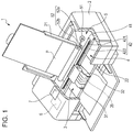
- Fig. 1 is a diagram schematically illustrating a configuration of an ink jet printer 1 (hereinafter, simply referred to as a "printer”) as a liquid droplet ejecting apparatus in a first embodiment. Also, in the description below, in Fig. 1 , an upper side in a vertical direction is referred to as an "upper portion", and a lower side in the vertical direction is referred to as a “lower portion”. Firstly, a mechanical configuration of the printer 1 is described.
- the printer 1 illustrated in Fig. 1 is provided with an apparatus main body 2, and a tray 21 to which a recording sheet P is installed is provided in the rearward upper portion, a paper discharging opening 22 that discharges the recording sheet P is provided in the forward lower portion, and an operation panel 7 is provided on the upper surface.
- the operation panel 7 is configured with, for example, a liquid crystal display, an organic EL display, and an LED lamp, and includes a display portion (not illustrated) that displays an error message or the like, and an operation portion (not illustrated) configured with various kinds of switches.
- a printing apparatus 4 including a printing section 3 which reciprocates, a paper feeding apparatus 5 that feeds and discharges the recording sheet P to and from the printing apparatus 4, and a control portion 6 that controls the printing apparatus 4 and the paper feeding apparatus 5 are included.
- the paper feeding apparatus 5 intermittently transmits the recording sheet P one by one under the control of the control portion 6.
- the recording sheet P passes through a portion near the lower portion of the printing section 3.
- the printing section 3 reciprocates in a direction substantially orthogonal to the direction of transmitting the recording sheet P, and performs printing on the recording sheet P. That is, the reciprocating of the printing section 3 and the intermittent transmission of the recording sheet P become main scanning and subscanning, to perform ink jet-type printing.
- the printing apparatus 4 includes the printing section 3, a carriage motor 41 that becomes a driving source that causes the printing section 3 to move (to reciprocate) in the main scanning direction, and a reciprocating driving mechanism 42 that receives the rotation of the carriage motor 41, and causes the printing section 3 to reciprocate.
- the printing section 3 includes a plurality of head units 35, an ink cartridge (I/C) 31 (liquid supply source) that supplies ink to the respective head units 35, and a carriage 32 to which the respective head units 35 and an ink cartridge 31 are mounted.
- I/C ink cartridge
- the ink cartridge 31 may not be mounted on the carriage 32, and instead may be installed in another location, and communicate with the head units 35 through a tube so that the ink is supplied (not illustrated).
- Such a configuration will be described in a second embodiment with reference to Fig. 21 .
- the ink cartridges 31 full color printing becomes possible by using cartridges filled with four colors of ink of yellow, cyan, magenta, and black, as the ink cartridges 31.
- the head units 35 respectively corresponding to each color are provided in the printing section 3.
- the four ink cartridges 31 corresponding to four colors of ink are illustrated in Fig. 1 , but the printing section 3 may be configured so as to further include the ink cartridges 31 including ink of other colors such as light cyan, light magenta, dark yellow, and special colors.
- the reciprocating driving mechanism 42 includes carriage guide shafts 422 supported by a frame (not illustrated) on both ends, and a timing belt 421 extending in parallel to the carriage guide shafts 422.
- the carriage 32 is supported by the carriage guide shafts 422 of the reciprocating driving mechanism 42 in a reciprocating manner, and is fixed to a part of the timing belt 421. If the timing belt 421 is forwardly and backwardly driven through a pulley by an operation of the carriage motor 41, the printing section 3 moves in a reciprocating manner, by being guided by the carriage guide shafts 422. Also, at the time of the reciprocating, ink drops are appropriately ejected from respective ink jet heads 100 of the head units 35 according to the image data to be printed (printing data), and printing on the recording sheet P is performed.
- the paper feeding apparatus 5 includes a paper feeding motor 51 as a driving source thereof, and paper feeding rollers 52 that rotate by the operation of the paper feeding motor 51.
- the paper feeding rollers 52 are configured with a driven roller 52a and a driving roller 52b that interpose a transportation route of the recording sheet P (the recording sheet P) and vertically face each other, and the driving roller 52b is connected to the paper feeding motor 51. Accordingly, the paper feeding rollers 52 transmit multiple sheets of recording sheet P installed in the tray 21 toward the printing apparatus 4 one by one, and discharge the multiple sheets of recording sheet P from the printing apparatus 4 one by one. Further, instead of the tray 21, a configuration in which a paper feeding cassette that accommodates the recording sheet P is mounted in a detachable manner is possible.
- the paper feeding motor 51 is interlocked with a reciprocating movement of the printing section 3, and transmits the recording sheet P according to a resolution of an image.
- a paper feeding movement and a paper transmitting movement may be performed by respective different motors, or may be performed by the same motor using a part that switches torque transmission such as an electromagnetic clutch.
- the control portion 6 performs a printing process on the recording sheet P by controlling the printing apparatus 4, the paper feeding apparatus 5, and the like based on data to be printed, which is input from a host computer 8 such as a personal computer (PC) or a digital camera (DC).
- a host computer 8 such as a personal computer (PC) or a digital camera (DC).
- the control portion 6 causes respective portions to perform corresponding processes based on a depression signal which is input from an operation portion, and generated by pressing various kinds of switches, together with causing a display portion of the operation panel 7 to display an error message or the like, causing an LED lamp to be turned on/off, or the like.
- the control portion 6 transmits information such as an error message or abnormal ejection to the host computer 8, if necessary.
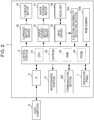
- the printer 1 includes an interface (IF) 9 that receives data relating to printing or the like which is input from the host computer 8, the control portion 6, the carriage motor 41, a carriage motor driver 43 that controls the driving of the carriage motor 41, the paper feeding motor 51, a paper feeding motor driver 53 that controls the driving of the paper feeding motor 51, the head units 35, a head driver 33 that controls the driving of the head units 35, an ejection abnormality detecting section 10A (the first detecting section), a RGB camera 10B (the second detecting section), an operation panel 7, a maintenance unit 72, and a communicating section 500. Also, the communicating section 500 will be described later with reference to Fig. 20 .
- IF interface
- the control portion 6 includes a central processing unit (CPU) 61 that performs various kinds of processes such as a printing process or an ejection abnormality detecting process, an electrically erasable programmable read-only memory (EEPROM) (storage section) 62 which is a kind of non-volatile semiconductor memory that stores the data to be printed which is input from the host computer 8 through the IF 9 in a data storage area (not illustrated), a random access memory (RAM) 63 that temporarily stores various kinds of data for performing the ejection abnormality detecting process described below, or temporarily stores an application program for the printing process or the like, and a PROM 64 that is a kind of non-volatile semiconductor memory that stores a control program that controls respective portions. Further, respective elements of the control portion 6 are electrically connected to each other through a bus (not illustrated).
- CPU central processing unit
- EEPROM electrically erasable programmable read-only memory
- storage section which is a kind of non-volatile semiconductor memory that stores the data to be
- the printing section 3 includes the plurality of head units 35 corresponding to respective colors of ink.
- the head units 35 each include a plurality of nozzles 110, and electrostatic actuators 120 respectively corresponding to the nozzles 110. That is, a head unit 35 is configured to include the plurality of ink jet heads 100 (liquid droplet ejecting heads) each of which has one set of the nozzles 110 and the electrostatic actuator 120.
- the head driver 33 is configured with a driving circuit 18 that controls ejection timings of ink by driving the electrostatic actuators 120 of the respective ink jet heads 100, and switching sections 23 (see Fig. 12 ).
- control portion 6 receives the data to be printed from the host computer 8 through the IF 9, the control portion 6 stores the data to be printed in the EEPROM 62. Also, the CPU 61 performs a predetermined process on the data to be printed, and outputs a driving signal to the respective drivers 33, 43, and 53 based on the processed data and the input data from the various kinds of sensors. If a driving signal is input through the respective drivers 33, 43, and 53, the plurality of electrostatic actuators 120 of the head units 35, the carriage motor 41 of the printing apparatus 4, and the paper feeding apparatus 5 are respectively operated. Accordingly, a printing process is performed on the recording sheet P.
- control portion 6 determines a replacement necessity of the ink jet head 100 based on the detected result from the ejection abnormality detecting section 10A and the RGB camera 10B (the detecting section). Specifically, after the maintenance unit 72 performs the maintenance operation, the control portion 6 determines that the ink jet head 100 needs to be replaced in a case in which either of whether or not the state inside the cavity 141 (to be described later) is not normal or whether or not the ejection state is not normal is detected by the detecting section a predetermined number of times. That is, the control portion 6 functions as a determination section in the present embodiment of the invention.
- control portion 6 checks whether or not the maintenance unit 72 functions normally, and then determines whether or not the ink jet head 100 is necessary to be replaced.
- the ejection abnormality detecting section 10A detects a vibration waveform of the cavity 141 before the maintenance operation, and detects the vibration waveform of the cavity 141 during the maintenance operation or after the maintenance operation.
- the control portion 6 determines that the maintenance unit 72 malfunctions in a case in which bubbles are determined to be increased inside the cavity 141 by the maintenance operation based on the vibration waveform detected by the ejection abnormality detecting section 10A.
- the control portion 6 causes the display portion of the operation panel 7 to be display an indication thereof, and notifies the indication to an operator. That is, the operation panel 7 functions as a notification unit in the invention.
- FIG. 3 is a cross-sectional view schematically illustrating the head unit 35 (the ink jet head 100) illustrated in Fig. 1
- Fig. 4 is an exploded perspective view schematically illustrating a configuration of the head unit 35 corresponding to a color of ink. Further, Figs. 3 and 4 are illustrated in a state of being turned upside down from the state of being generally used.
- the head unit 35 is connected to the ink cartridge 31 through an ink intake opening 131, a damper chamber 130, and an ink supplying tube 311.
- the damper chamber 130 includes a damper 132 made of rubber. Since the damper chamber 130 is capable of absorbing the shaking of ink and the change of ink pressure caused when the carriage 32 reciprocates, it is possible to stably supply a predetermined amount of the ink to the head unit 35.
- the head unit 35 has a three-layer structure in which a silicon substrate 140 is interposed between a nozzle plate 150 made of silicon in the same manner stacked on the upper side and a glass substrate (glass substrate) 160 made of borosilicate having a similar coefficient of thermal expansion stacked on the lower side.
- Grooves functioning as a plurality of independent cavities (pressure chambers) 141, one reservoir (common ink chamber) 143, and ink supplying openings (orifices) 142 that communicate the reservoir 143 with the cavities 141 are formed in the silicon substrate 140 in the center.
- respective grooves can be formed by performing an etching process on the surface of the silicon substrate 140.
- the nozzle plate 150, the silicon substrate 140, and the glass substrate 160 are bonded in this sequence, and the respective cavities 141, the reservoir 143, the respective ink supplying openings 142 are partitioned and formed.
- the cavities 141 are respectively formed in a strip shape (rectangular shape), the capacities thereof are changed according to vibrations (displacements) of vibration plates 121 described below, and the cavities 141 are configured so that ink (liquid material) is ejected from the nozzles 110 according to the changes of the capacities.
- the nozzle plate 150 the nozzles 110 are formed at positions corresponding to portions on the distal end sides of the respective cavities 141, and these are communicated with the respective cavities 141.
- the ink intake opening 131 is formed that is communicated with the reservoir 143 in a portion of the glass substrate 160 in which the reservoir 143 is positioned.
- the ink is supplied from the ink cartridge 31 to the reservoir 143 through the ink supplying tube 311 (the liquid supply path), the damper chamber 130, and the ink intake opening 131.
- the ink supplied to the reservoir 143 is supplied to the respective independent cavities 141 through the respective ink supplying openings 142. Further, the respective cavities 141 are partitioned and formed by the nozzle plate 150, side walls (partitions) 144, and bottom walls 121.
- the bottom walls 121 thereof are formed with thin walls, the bottom walls 121 are configured to function as vibration plates (diaphragms) that can be elastically deformed (elastically displaced) in the off-plate direction (thickness direction), that is, in the vertical direction in Fig. 3 . Accordingly, for convenience of explanation below, the portions of the bottom walls 121 are described by being called the vibration plates 121 (that is, hereinafter, both of the "bottom walls” and the “vibration plates” use the reference numeral 121).
- Shallow concave portions 161 are formed at positions corresponding to the respective cavities 141 of the silicon substrate 140 on the surface on the silicon substrate 140 side of the glass substrate 160. Accordingly, the bottom walls 121 of the respective cavities 141 are opposed to surfaces of facing walls 162 of the glass substrate 160 on which the concave portions 161 are formed with the predetermined gaps interposed therebetween. That is, apertures having a predetermined thickness (for example, about 0.2 microns) exist between the bottom walls 121 of the cavities 141 and segment electrodes 122. Further, the concave portions 161 can be formed by, for example, etching.
- the respective bottom walls (vibration plates) 121 of the cavities 141 configure a portion of common electrodes 124 on the cavities 141 side respectively for accumulating electric charges by driving signals supplied from the head driver 33. That is, the respective vibration plates 121 of the cavities 141 also function as a portion of corresponding facing electrodes (facing electrodes of capacitor) of the electrostatic actuators 120. Also, the segment electrodes 122 that are electrodes respectively facing the common electrodes 124 are formed so as to oppose the respective bottom walls 121 of the cavities 141 on the surfaces of the concave portions 161 of the glass substrate 160. In addition, as illustrated in Fig.
- the respective surfaces of the bottom walls 121 of the cavities 141 are covered with an insulation layer 123 made of a silicon oxide film (SiO2).
- SiO2 silicon oxide film
- the respective bottom walls 121 of the cavities 141 that is, the vibration plates 121 and the respective segment electrodes 122 corresponding thereto form (configure) facing electrodes (facing electrodes of capacitor) with the insulation layer 123 formed on the surface on the lower side of the bottom walls 121 of the cavities 141 in Fig. 3 and apertures in the concave portions 161.
- main portions of the electrostatic actuators 120 are configured with the vibration plates 121, the segment electrodes 122, and the insulation layer 123 and the apertures interposed therebetween.
- the head driver 33 including the driving circuit 18 for applying a driving voltage between the facing electrodes charges and discharges electricity between the facing electrodes according to a printing signal (printing data) input from the control portion 6.
- An output terminal on one side of a head driver 33 is connected to the respective segment electrodes 122, and the other output terminal is connected to input terminals 124a of the common electrodes 124 formed on the silicon substrate 140.
- impurities are injected into the silicon substrate 140, and the silicon substrate 140 itself has conductivity. Therefore, it is possible to supply a voltage from the input terminals 124a of the common electrodes 124 to the common electrodes 124 of the bottom walls 121.
- a thin film made of a conductive material such as gold or copper may be formed on one surface of the silicon substrate 140. Accordingly, it is possible to supply a voltage (charge) to the common electrodes 124 with low electric resistance (effectively).
- the thin film may be formed by, for example, evaporation or sputtering.
- a conductive film used as an electrode in the anode joining is formed on a path forming surface side of the silicon substrate 140 (upper portion of the silicon substrate 140 illustrated in Fig. 3 ).
- the conductive film is used as the input terminal 124a of the common electrode 124. Further, for example, the input terminal 124a of the common electrodes 124 may be omitted, and also the method of bonding the silicon substrate 140 and the glass substrate 160 is not limited to the anode joining.
- the head unit 35 includes the nozzle plate 150 in which the plurality of nozzles 110 are formed, the silicon substrate (ink chamber substrate) 140 in which the plurality of cavities 141, the plurality of ink supplying openings 142, and the one reservoir 143 are formed, and the insulation layer 123, and these are stored in a base body 170 including the glass substrate 160.
- the base body 170 is configured with, for example, various kinds of resin materials, and various kinds of metal materials, and the silicon substrate 140 is fixed to and supported by the base body 170.
- Figs. 5A to 5C are diagrams illustrating respective states of the cross section taken along a line V-V in Fig. 3 when a driving signal is input. If the driving voltage is applied between facing electrodes from the head driver 33, Coulomb force is generated between the facing electrodes, and the bottom wall (vibration plate) 121 bends toward the segment electrode 122 side from the initial state ( Fig. 5A ) so that the capacity of the cavity 141 increases ( Fig. 5B ).
- the respective vibration plate 121 of the cavity 141 performs damped vibrations by a series of operations (an ink ejection operation by a driving signal of the head driver 33) until a next driving signal (driving voltage) is input, and a next ink drop is ejected.
- the damped vibration is referred to as a residual vibration. It is assumed that the residual vibration of the vibration plate 121 has a natural vibration frequency determined by an acoustic resistance r determined by shapes of the nozzles 110 or the ink supplying openings 142, or a coefficient of viscosity of the ink, inertance m determined by a weight of the ink in the path, and a compliance Cm of the vibration plate 121.
- FIG. 6 is a circuit diagram illustrating a calculation model of the simple harmonic vibration assuming the residual vibration of the vibration plate 121.
- the calculation model of the residual vibration of the vibration plate 121 is expressed by an acoustic pressure P, the inertance m, the compliance Cm, and the acoustic resistance r which are described above.
- a step response with respect to a volume velocity u when the acoustic pressure P is applied to a circuit in Fig. 6 is calculated, the following expressions can be obtained.
- Fig. 7 is a graph illustrating a relationship between the experimental value and the calculated value of the residual vibration of the vibration plate 121. As can be understood from the graph illustrated in Fig. 7 , two waveforms of the experimental value and the calculated value are substantially identical to each other.
- the liquid droplet When the abnormal ejection is generated, the liquid droplet typically is not ejected from the nozzles 110 as a result, that is, the non-ejection phenomenon of the liquid droplet is performed. In this case, dot omission of pixels in an image printed (drawn) on the recording sheet P occurs. In addition, if the abnormal ejection occurs, even if the liquid droplet is ejected from the nozzles 110, since an amount of the liquid droplet is too small, or the direction of flight (trajectory) of the liquid droplet is deviated, the liquid droplet does not impact on an appropriate portion. Therefore, dot omission in the image occurs. Accordingly, in the description below, the abnormal ejection of the liquid droplet may also be referred to as "dot omission".
- values of the acoustic resistances r or the inertances m are adjusted according to causes of the dot omission (abnormal ejection) phenomenon (non-ejection phenomenon of liquid drop) in the printing processes that are generated in the nozzles 110 of the ink jet heads 100, so that the calculated values and the experimental values of the residual vibrations of the vibration plates 121 match with each other.
- FIG. 8 is a conceptual diagram illustrating a portion near the nozzle 110 when a bubble B is mixed into the cavity 141 in Fig. 3 . As illustrated in Fig. 8 , it is assumed that the generated bubble B is generated and attached on a wall surface of the cavity 141 (as an example of the attachment position of the bubble B, Fig. 8 illustrates a case in which the bubble B is attached near the nozzle 110).
- the acoustic resistance r and the inertance m match with the experimental values of the residual vibration when the bubble is mixed by setting the acoustic resistance r and the inertance m to be smaller than those in the case of Fig. 7 in which the ink is normally ejected so that the result (graph) as illustrated in Fig. 9 can be obtained.
- a characteristic residual vibration waveform in which a frequency becomes higher than in the normal ejection can be obtained.
- a damping rate of amplitude of the residual vibration is decreased by the decrease of the acoustic resistance r or the like. Therefore, it is checked that the amplitude of the residual vibration is slowly decreased.
- FIG. 10 is a conceptual diagram illustrating a portion near the nozzle 110 when the ink is dried and adhered near the nozzle 110 in Fig. 3 .
- the state becomes as if the ink in the cavity 141 is trapped in the cavity 141. In this manner, if the ink near the nozzle 110 is dried and thickened, it is considered that the acoustic resistance r increases.
- the acoustic resistance r matches with the experimental values of the residual vibration when the ink is dried, and adhered (thickened) near the nozzle 110 by setting the acoustic resistance r to be greater than that in the case of Fig. 7 in which the ink is normally ejected so that the result (graph) as illustrated in Fig. 11 can be obtained.
- the experimental value expressed in Fig. 11 is obtained by measuring the residual vibration of the vibration plate 121 in a state in which the head unit 35 without mounting a cap (not illustrated) is left for several days, and the ink near the nozzle 110 is dried and thickened so that the ink is not ejected (the ink is adhered). As can be understood from the graphs of Figs.
- the paper dust attachment near an outlet of the nozzle 110 which is still another cause of the dot omission is discussed.
- the ink leaks through the paper dust from the inside of the cavity 141, and also the ink does not eject from the nozzle 110.
- the ink in the cavity 141 and the leaked ink are more than in the normal state, so it is considered that the inertance m increases.
- the acoustic resistance r increases by the fiber of the paper dust attached near the outlet of the nozzle 110. Accordingly, a characteristic residual vibration waveform, in which when the paper dust is attached near the outlet of the nozzle 110, the frequency is lower than in the normal ejection, and the frequency of the residual vibration is higher than in the drying of the ink, can be obtained.
- Fig. 12 is a block diagram schematically illustrating the ejection abnormality detecting section 10A illustrated in Fig. 3 .
- the ejection abnormality detecting section 10A includes an oscillation circuit 11, an F/V converting circuit 12, a residual vibration detecting section 16 configured with a waveform shaping circuit 15, a measurement section 17 that measures a cycle, an amplitude, or the like from residual vibration waveform data detected by the residual vibration detecting section 16, and a determination section 20 that determines the abnormal ejection of the ink jet heads 100 based on the cycle or the like measured by the measurement section 17.
- the oscillation circuit 11 oscillates based on the residual vibrations of the vibration plate 121 of the electrostatic actuator 120, the F/V converting circuit 12 and the waveform shaping circuit 15 form vibration waveforms from the oscillation frequency, and the residual vibration detecting section 16 detects the vibration waveforms.
- the measurement section 17 measures the cycle or the like of the residual vibration based on the detected vibration waveform, and the determination section 20 detects and determines the abnormal ejection of the respective ink jet heads 100 included in the respective head units 35 of the printing section 3 based on the cycle or the like of the measured residual vibration. That is, the ejection abnormality detecting section 10A corresponds to the first detecting section in the present embodiment of the invention.
- the printer 1 is provided a supporting stand 71 which supports the recording sheet P inside the apparatus main body 2, and a maintenance unit 72 for performing a maintenance of the ink jet head 100.
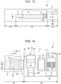
- the supporting stand 71 is arranged near the center in a scanning area that extends in the main scanning direction of the carriage 32 (in the horizontal direction in Figs. 13 and 14 ), while the maintenance unit 72 is arranged in the end portion of the same scanning area.
- a side on which the maintenance unit 72 is arranged in the main scanning direction (right side in Fig. 13 ) may be referred to as a "1-digit side”
- the other side left side in Fig. 13
- 80-digit side 80-digit side
- first scanning direction +X movement direction of the carriage 32 from the 1-digit side to the 80-digit side
- second scanning direction -X movement direction of the carriage 32 from the 80-digit side to the 1-digit side
- the supporting stand 71 may be incorporated with a heat generating body so as to function as a drying mechanism for promoting drying of the recording sheet P to which liquid droplets are received.
- the drying mechanism for promoting drying of the recording sheet P the heat generating body that heats the recording sheet P from the upper side of the carriage 32 or a blowing apparatus that blows toward the recording sheet P may be provided.
- the area in which the supporting stand 71 is arranged becomes a recording area PA in which liquid droplets are ejected from the ink jet head 100 to the recording sheet P, while the area in which the maintenance unit 72 is arranged becomes a non-recording area NA in which the recording (printing) on the recording sheet P is not performed.
- the speed of the carriage 32 is decreased in the non-recording area NA on the 80-digit side, and its direction is changed at an end portion in the main scanning direction.
- the carriage 32 that has changed the direction increases the speed in the non-recording area NA on the 80-digit side
- the carriage 32 moves inwardly of the recording area PA again in the second scanning direction -X at a substantially constant speed.
- the non-recording area NA is also an area in which the reciprocating carriage 32 changes direction.
- the ink jet head 100 reciprocates between the recording area PA in which the recording sheet P is arranged, and the non-recording area NA which is positioned outside the recording area PA.
- one scanning (movement) of the carriage 32 in the first scanning direction +X or the second scanning direction -X is referred to as one pass
- a belt-shaped area Ln area indicated with alternate long and two short dashed lines in Fig. 13
- the changing of the direction by the carriage 32 in the non-recording area NA is referred to as a return.
- the recording sheet P is arranged on the supporting stand 71, or is retreated from the supporting stand 71 by being transported in a transportation direction Y in the subscanning direction intersecting to the main scanning direction by the paper feeding apparatus 5 (see Fig. 1 ).
- the recording sheet P is transported in a predetermined distance (distance corresponding to one line) in the transportation direction Y, while the carriage 32 changes the direction in the non-recording area NA. That is, the printer 1 performs recording on the entire recording sheet P by performing the recording for one line in the recording area PA and the intermittent transportation of the recording sheet P.
- the plurality of nozzles 110 are lined up in the subscanning direction to form a nozzle array 110N, and also the plurality of nozzle arrays 110N are arranged along the main scanning direction.
- the plurality of nozzles 110 that configure the nozzle array 110N are nozzles that discharge the same kind of liquid (for example, the same color of ink), and the plurality of nozzle arrays 110N are arrays that discharge different kinds of liquid (for example, ink of different colors: cyan, magenta, yellow, black, and the like).
- the maintenance unit 72 arranged in the non-recording area NA on the 1-digit side includes a wiping unit 81, a flushing unit 74 having a liquid receiving portion 73, and a cleaning mechanism 91 which are arranged to be lined up from a position near the recording area PA in the main scanning direction.
- the wiping unit 81 includes a wiping member 82 that can absorb liquid, a holding mechanism 83 that holds the wiping member 82, and a wiping motor 84.
- the wiping member 82 can realize a configuration in which liquid is absorbed in a gap between fibers of synthetic resins, by being formed with, for example, non-woven fabric made of synthetic resins or the like.
- the wiping member 82 is detachably attached to the holding mechanism 83. Therefore, the wiping member 82 can be replaced into a new one after use or the like. If the wiping member 82 is attached to the holding mechanism 83, a portion thereof protrudes to the outside, and the wiping member 82 functions as a wiping portion 85 that can wipe a nozzle surface 36 in which the nozzles 110 of the ink jet head 100 are open.
- the holding mechanism 83 is supported by a pair of guiding shafts 86 extending in the subscanning direction, and moves in the subscanning direction along the guiding shafts 86 by the driving force of the wiping motor 84 when the wiping motor 84 is driven, so that the wiping portion 85 wipes the nozzle surface 36.
- the cleaning mechanism 91 includes at least one cap 92 for suction, a plurality of caps 93 for moisturization, a sucking pump 94, and a capping motor 95. If the capping motor 95 is driven, the caps 92 and 93 relatively move in a direction to be close to the ink jet head 100 so that a closed space in which the plurality of nozzles 110 that form the nozzle array 110N are enclosed is formed.
- the cap 92 for suction forms a closed space in which a portion (for example, the nozzles 110 that eject the same kind of liquid) of the plurality of nozzles 110 is open. Also, if the sucking pump 94 is driven in a state in which the cap 92 for suction forms the closed space, negative pressure is created within the closed space, and the suction cleaning (pump suction process) in which the ink is ejected from the nozzles 110 which are open to the closed space is performed.
- the suction cleaning is a kind of maintenance operations which is performed in order to solve the abnormal ejection of the nozzles 110, and is performed for each nozzle group enclosed with the cap 92 for suction.
- the caps 93 for moisturization suppress the nozzles 110 from being dried by forming closed spaces to which the nozzles 110 are open.
- the caps 93 for moisturization are provided for each nozzle array 110N, and form closed spaces in a shape of dividing the plurality of nozzles 110 in the nozzle array unit. Also, a configuration of the caps 93 for moisturization will be described later in detail.
- the ink jet head 100 When the recording is not performed, or the electric power is turned off, the ink jet head 100 is moved to a stand-by position HP in which the caps 93 for moisturization are arranged. Then, the caps 93 for moisturization relatively move in a direction to come close to the ink jet head 100 to form the closed spaces to which the nozzles 110 are open. In this manner, enclosing a space to which the nozzles 110 are open by the cap 92 or the caps 93 is referred to as capping. Also, when the recording is not performed, the inkjet head 100 is capped by the caps 93 for moisturization in the stand-by position HP.
- the ink jet head 100 when the ink jet head 100 is arranged in a position corresponding to the liquid receiving portion 73 (for example, upper side of the liquid receiving portion 73 in the vertical direction), the ink jet head 100 performs a flushing process for ejecting liquid droplets to the liquid receiving portion 73.
- the clogging of the nozzles 110 is prevented or solved by performing the flushing operation in which the ink jet head 100 periodically ejects the liquid droplets to the liquid receiving portion 73 when performing the recording process on the recording sheet P.
- the flushing which is periodically performed in the non-recording area NA between the recording operations in the recording area PA is distinguished from the flushing as a restoration operation (maintenance operation) when the ink is thickened, and is referred to as periodic flushing.
- the periodic flushing may be performed whenever the ink jet head 100 reciprocates once in the scanning area, and arranged in the position corresponding to the liquid receiving portion 73, or whenever the ink jet head 100 reciprocates a plurality of times.
- the liquid droplets may be ejected from a portion of the nozzles 110, and the liquid droplets may be ejected from all the nozzles 110.
- the RGB camera 10B will be described with reference to Fig. 14 .
- the RGB camera 10B is provided on one end portion (an end portion of a left side in Fig. 14 ) of the carriage 32 in the main scanning direction, and detects the ejection state of the liquid droplets by reading a pattern which is formed on the recording sheet P by ejecting the liquid droplets from the nozzle 110. That is, the RGB camera 10B corresponds to the second detecting section in the present embodiment of the invention.
- the RGB camera 10B is capable of reading a color image by RGB color separation.
- the control portion 6 determines that the ejection state of the ink is not normal in a case in which a quality of the pattern formed on the recording sheet P detected by the RGB camera 10B exceeds a predetermined allowable amount (for example, in a case in which the landing position of the ink is not in a predetermined area).
- caps 93 for moisturization will be described with reference to Figs. 15 to 19 .
- a moisturizing mechanism 361 as an example of a maintenance unit includes a cap holder 362 and a moisturizing cap 363 held by the cap holder 362.
- the moisturizing cap 363 includes the cap 93 as an example of a cap section, which comes into contact with the head unit 35 and closes the space 263 (see Fig. 18 ) which the nozzle 110 faces, and a support portion 365 that supports at least one cap 93.
- each of the caps 93 includes a frame 367 which is made of an elastic material such as an elastomer and substantially has an oblong shape in a plan view, and a rigid member 368 fitted into the frame 367.
- the rigid member 368 is configured of a hard synthetic resin having high gas barrier properties such as polypropylene (PP). Further, as a material of the rigid member 368, any hard materials having high gas barrier properties can be employed, and, for example, polyethylene (PE), polyethylene terephthalate (PET), or the like may be employed.
- PP polypropylene
- any hard materials having high gas barrier properties can be employed, and, for example, polyethylene (PE), polyethylene terephthalate (PET), or the like may be employed.
- the rigid member 368 has a main body 370 substantially having a rectangular parallelepiped shape and a protrusion section 371 which protrudes from the main body 370 and has a circular tube shape. That is, the protrusion section 371 has a hollow portion 372 inside.
- a surface of the main body 370, on which the protrusion section 371 is formed is referred to as an under surface and a surface opposite to the under surface is referred to as a top surface 370a. That is, the top surface 370a means a surface which configures an inner bottom of the cap 93 in a case in which the rigid member 368 is fitted into the frame 367.
- longitudinal and traverse directions mean directions intersecting with the vertical direction and direction of the long side and short side of the main body 370, respectively.
- one of both side surfaces in the traverse direction is referred to as a first side surface 370b and the other surface is referred to as a second side surface 370c.
- a recessed section 374 is formed in the top surface 370a of the main body 370 at the center position in the longitudinal direction across the traverse direction.
- a convex portion 375 extending in the traverse direction and a cover section 376 substantially having a rectangular plate shape in a plan view are formed on the inner bottom of the recessed section 374 to be integral to the main body 370.
- an annular concave portion 377 is formed on the boundary between the convex portion 375 and the cover section 376.
- Step portions 378 are formed on both side surfaces of the cover section 376 in the traverse direction, respectively. Further, both ends of the step portion 378 in the longitudinal direction are bent at a right angle downward and inclined to become wider obliquely downward.
- a through-hole 380 which penetrates the main body 370 from the first side surface 370b in the traverse direction is formed. Moreover, a first groove 381 which connects the through-hole 380 and the annular concave portion 377 is formed to meander on the first side surface 370b.
- the first groove 381 is configured to have first to third longitudinal grooves 381a to 381c extending in the longitudinal direction and first to third vertical grooves 381d to 381f extending in the vertical direction. Further, the first to third longitudinal grooves 381a to 381c are formed at positions different in the vertical direction and the first to third vertical grooves 381d to 381f are formed at positions different in the longitudinal direction and the vertical direction.
- first longitudinal groove 381a connects the through-hole 380 and the lower end of the first vertical groove 381d.
- second longitudinal groove 381b connects the upper end of the first vertical groove 381d and the lower end of the second vertical groove 381e
- third longitudinal groove 381c connects the upper end of the second vertical groove 381e and the lower end of the third vertical groove 381f.
- the upper end of the third vertical groove 381f faces the under surface of the cover section 376.
- a second groove 382 whose one end is connected to the through-hole 380, is formed and a connection hole 383 which connects the other end of the second groove 382 and the hollow portion 372 is formed, on the second side surface 370c. That is, the second groove 382 is formed to meander so as to connect the through-hole 380 and the connection hole 383.
- the second groove 382 is configured to have a fourth longitudinal groove 382a and a fifth longitudinal groove 382b which extend in the longitudinal direction and fourth to sixth vertical grooves 382c to 382e which extend in the vertical direction.
- the fourth longitudinal groove 382a and the fifth longitudinal groove 382b are formed at positions different in the vertical direction and the fourth to sixth vertical grooves 382c to 382e are formed at positions different in the longitudinal direction.
- the lower end of the fourth vertical groove 382c is connected to the through-hole 380.
- the fourth longitudinal groove 382a connects the upper end of the fourth vertical groove 382c and the upper end of the fifth vertical groove 382d and the fifth longitudinal groove 382b connects the lower end of the fifth vertical groove 382d and the upper end of the sixth vertical groove 382e.
- the lower end of the sixth vertical groove 382e is connected to the connection hole 383.
- the first side surface 370b and the second side surface 370c of the rigid member 368 comes into close contact with an inner surface of the frame 367. Accordingly, openings of the first groove 381, the second groove 382, the through-hole 380, and the connection hole 383 are covered with the inner surface of the frame 367 and the grooves and the hole becomes an air path. A gap between the main body 370 and the cover section 376 becomes an air path. Accordingly, the air paths and the hollow portion 372 configure an air communicating section 384 through which the airtight space 263, which the nozzle 110 faces, and air communicate with each other.
- the airtight space 263 means a space, which the nozzle 110 faces and which is closed, when the cap 93 comes into contact with the head unit 35.
- the moisturizing mechanism 361 performs a capping operation as an example of the maintenance operation of the head unit 35, with the cap 93 coming into contact with the head unit 35 and closing the space 263 which the nozzle 110 faces.
- the moisturizing cap 363, as an expendable item malfunctions and it is not possible to perform complete closing of the airtight space 263 in a state in which the airtight space 263, which the nozzle 110 faces, communicates with air.
- the moisturizing mechanism 361 includes a cam mechanism 386 which causes the cap holder 362 to be lifted and lowered and thereby enables the cap 93 to come into contact with or to be separated from the head unit 35. That is, the moisturizing cap 363 and the cap holder 362 are configured to be able to be integrally lifted and lowered by the cam mechanism 386.
- the moisturizing mechanism 361 has a regulation section 387 which comes into contact with the lifted cap holder 362 and regulates a movement thereof.
- the cam mechanism 386 has a rotating shaft 388 which rotates by rotary drive of the capping motor 95 (see Fig. 14 ) and a cam frame 389 which substantially has a triangular shape and is fixed at a base end section to the rotating shaft 388.
- a shaft 391 of a cam roller 390 is pivotally supported by a distal end portion of the cam frame 389 in a rotatable manner.
- the shaft 391 of the cam roller 390 is configured to penetrate the cam frame 389 and to protrude from both side surfaces of the cam frame 389. Accordingly, when the cam frame 389 rotates around the rotating shaft 388 along with the rotation of the rotating shaft 388, the cam roller 390 pivotally supported on the distal end portion of the cam frame 389 performs a circular motion around the rotating shaft 388.
- a cam groove 393 is formed at a position on the cap holder 362, which corresponds to the cam mechanism 386.
- the cam groove 393 has an opening 394 which opens downward and the cap holder 362 is supported by the cam mechanism 386 when the cam mechanism 386 is inserted through the opening 394.
- the cam groove 393 of the cap holder 362 has a flat surface section 395 which is positioned above the opening 394 and a first inclined surface section 396 continuous from the flat surface section 395. Further, a concave surface section 397 and a second inclined surface section 398 continuous from the concave surface section 397 are formed at positions on the cam groove 393, which can come into contact with both ends of the shaft 391. Furthermore, the first inclined surface section 396 and the second inclined surface section 398 are formed to have gradients which are substantially parallel to each other.
- the malfunction detecting process of the moisturizing cap 363 is performed on the regular basis or based on an instruction by a user.
- the control portion 6 detects the vibration waveform of the cavity 141 before the cap 93 closes a space using the ejection abnormality detecting section 10A after performing the suction cleaning. Subsequently, the control portion 6 causes the caps 93 for moisturization to come into close contact with the head unit 35. That is, the control portion 6 causes the carriage 32 to be moved by inputting a signal to the carriage motor driver 43, and so causes the nozzle 110 to move to a position which corresponds to the cap 93. Also, the control portion 6 drives the capping motor 95 to cause the rotating shaft 388 to rotate in the forward direction, the cap 93 is lifted, and thereby the capping operation is performed.
- the control portion 6 causes the cap 93 for moisturization to be opened. That is, the control portion 6 drives the capping motor 95 to cause the rotating shaft 388 to rotate in the backward direction and the cap 93 is lowered. Subsequently, the control portion 6 detects the vibration waveform of the cavity 141, after the cap 93 which closes the space opens the space, using the ejection abnormality detecting section 10A. Then, the control portion 6 determines whether or not bubbles are mixed in the nozzle 110 or the cavity 141 by comparing the two vibration waveforms. In a case where the bubbles are not increased in the nozzle 110 or in the cavity 141, the control portion 6 ends the malfunction detecting process of the cap 93.
- control portion 6 determines the air communicating section 384 malfunctions in a case in which the number of the cavities 141 in which the bubbles are mixed is increased by a test after the cap 93 which closes the space opens the space more than the number of cavities 141 in which the bubbles are mixed by a test before the cap 93 closes the space, causes the operation panel 7 as an example of the notification unit to display a notification for a replacement necessity of the caps 93 for moisturization, and ends the malfunction detecting process of the cap 93.
- the control portion 6 of the printer 1 checks that the maintenance unit 72 normally functions, and then determines the replacement necessity of the ink jet head 100.
- the control portion 6 detects the vibration waveform of the cavity 141 before the maintenance operation using the ejection abnormality detecting section 10A, detects the vibration waveform of the cavity 141 either during the maintenance operation or after the maintenance operation, based on the detected vibration waveform, and determines whether or not the bubbles inside the cavity 141 are increased by the maintenance operation (maintenance unit normality determining process: S1).
- the control portion 6 is capable of employing the malfunction detecting process of the cap 93 or the like described above.
- the control portion 6 determines that the maintenance unit 72 malfunctions, and causes the operation panel 7 to display an indication thereof (malfunction displaying process: S2).
- the control portion 6 determines whether or not an abnormality of the state inside the cavity 141 is detected by the ejection abnormality detecting section 10A a predetermined number of times (pressure chamber abnormality determining process: S3), and determines whether or not a normality of the ejection state of the ink is detected by the RGB camera 10B a predetermined number of times (landing abnormality determining process: S4).
- the control portion 6 determines replacement of the ink jet head 100 is not necessary (replacement unnecessity determining process: S5), and ends the control.
- the control portion 6 determines a replacement of the ink jet head 100 is necessary (replacement necessity determining process: S6), and causes the operation panel 7 to display an indication so as to notify the operator (replacement information displaying process: S7). After that, the control is ended.
- the printer 1 according to the embodiment will be described as an example of a remote monitoring system through a network.
- Fig. 21 is a diagram illustrating a configuration of a remote monitoring system 600.
- a centralized system of a plurality of printers 1A, 1B, and 1C using a computer of a remote monitoring center (hereinafter, referred to as an "information management device for remote-monitoring") 610 is exemplified.
- three of the printers 1A, 1B, and 1C are illustrated in Fig. 21 , but the number of printers to be monitored is not particularly limited.
- Each of the printers 1A, 1B, and 1C is communicably connected to the information management device for remote-monitoring 610 through a communication line 620.
- An aspect of the communication line 620 is not particularly limited, and may be a local LAN, or may be a wide area communication network (WAN) such as Internet, for example.
- a communication method is not particularly limited, and may for example be a wired or wireless manner or may be a combination thereof.
- Each of the printers 1A, 1B, and 1C is provided with a communicating section 500 ( Fig. 2 ) which is communicably connected to the information management device for remote-monitoring 610 as an external device, and is configured to be capable of transmitting information relating to the state inside the cavity 141 detected by the ejection abnormality detecting section 10A and information relating to the ejection state of the ink detected by the RGB camera 10B to the information management device for remote-monitoring 610 through the communication line 620.
- the information management device for remote-monitoring 610 stores information collected from each of the printers 1A, 1B, and 1C to a storage device 612, and collects and manages information relating to the state inside the cavity 141 detected by the ejection abnormality detecting section 10A and information relating to the ejection state of the ink detected by the RGB camera 10B by device and model.
- the information management device for remote-monitoring 610 calculates a time t (time taken for generating the abnormal ejection once) used for calculating prediction of generation of the abnormal ejection based on the collected information, and provides the information to each of the printers 1A, 1B, and 1C as needed. Accordingly, each of the printers 1A, 1B, and 1C is capable of predicting generation of the abnormal ejection using the newest parameter.
- the information management device for remote-monitoring 610 is communicably connected to a computer of a service center (hereinafter, referred to as a "service center device”.) 630 which provides a maintenance service.
- the information management device for remote-monitoring 610 is provided with a maintenance service request information generating section which generates information for requesting a necessity of a call for a service man or woman (i.e. a service operative), with respect to the printers 1A, 1B, and 1C which are determined to be required to replace the ink jet head 100, based on the state inside the cavity 141 detected by the ejection abnormality detecting section 10A and the ejection state of the ink detected by the RGB camera 10B.
- the information management device for remote-monitoring 610 transmits the information generated by the maintenance service request information generating section to the service center device 630.
- the service center device 630 generally manages the maintenance request information, and supports a task of dispatching a service man. In this way, the service man is dispatched from the service center to the corresponding device, and performs a required maintenance work such as a head replacement.
- the information management device for remote-monitoring 610 and the service center device 630 may be connected to each other by a local LAN, and may be connected to each other by a wide area network (WAN) such as Internet.
- WAN wide area network
- an aspect in which the information management device for remote-monitoring 610 and the service center device 630 are realized by a common computer is possible.
- the ejection abnormality detecting section 10A (the first detecting section) is capable of detecting the state inside the cavity 141
- the RGB camera 10B (the second detecting section) is capable of detecting the ejection state of the liquid droplets (amount of landing deviation).
- replacement of the ink jet head 100 can be determined to be necessary. Accordingly, with reference to the two detected results, necessity of the replacement of the ink jet head 100 can be accurately determined.
- an indication thereof can be notified to an operator (for example, a user or a service man) using the operation panel 79 (notification unit).
- the control portion 6 is capable of checking that the maintenance unit 72 normally functions, and then determining that replacement of the ink jet head 100 is necessary.
- the detecting section (the ejection abnormality detecting section 10A and the RGB camera 10B) cannot accurately detect the state of the ink jet head 100, or the nozzle 110 or the state inside the cavity 141 may be deteriorated.
- the maintenance unit 72 is checked to normally function, and then a replacement necessity of the ink jet head 100 can be determined. Thus, it is possible to perform determination based on the accurate detection result, and to prevent deterioration of the nozzle 110 or the state inside the cavity 141.
- the ejection abnormality detecting section 10A detects the vibration waveform of the cavity 141 before the cap 93 closes a space, and detects the vibration waveform of the cavity 141 after the cap 93 which closed the space opens the space; in a case in which a change of the state inside the cavity 141 indicates the increase of the bubbles inside the cavity 141, the control portion 6 is capable of determining that the air communicating section 384 malfunctions.
- the air communicating section 384 may not perform a function of communicating between a space closed with the cap 93 which is a space that the nozzle 110 faces and the air, for example, due to attachment and solidification of the liquid.
- a replacement necessity of the ink jet head 100 can be determined based on information relating to the state inside the cavity 141 detected by the ejection abnormality detecting section 10A and information relating to the ejection state of the ink detected by the RGB camera 10B (amount of landing deviation).
- the remote monitoring system 600 is provided with the maintenance service request information generating section which generates information for requesting a call for a service man with respect to the printers 1A, 1B, and 1C which are determined to require replacement of the ink jet head 100 based on the state inside the cavity 141 detected by the ejection abnormality detecting section 10A and the ejection state of the ink detected by the RGB camera 10B. Therefore, in a case in which the replacement of the ink jet head 100 is determined to be necessary, a call for a service man can be requested, and thus it is possible to provide an appropriate maintenance service.
- the printer 1 is provided with the head unit 35, and at least one supply mechanism 261 which can supply the liquid (for example, ink) contained in the ink cartridge 31 as an example of a liquid supply source, to the head unit 35. That is, the supply mechanism 261 supplies the liquid from the ink cartridge 31 through a liquid supply path 262 to the head unit 35. Also, the head unit 35 has the plurality of nozzles 110 from which the liquid supplied by the supply mechanism 261 is ejected as the liquid droplets, ejects the liquid droplets from the nozzles 110 to the recording sheet P (see Fig. 1 ) as an example of a medium, and performs a recording process.
- the supply mechanism 261 supplies the liquid from the ink cartridge 31 through a liquid supply path 262 to the head unit 35.
- the head unit 35 has the plurality of nozzles 110 from which the liquid supplied by the supply mechanism 261 is ejected as the liquid droplets, ejects the liquid droplets from the nozzles 110 to the recording sheet P (see
- the ink cartridge 31 according to the embodiment is not mounted in the carriage 32 but is disposed at a place other than the carriage 32. Also, even in a case in which a plurality of supply mechanisms 261 are provided, a configuration of each supply mechanism 261 is the same, and thus Fig. 22 illustrates one supply mechanism 261 and description of other supply mechanisms is omitted.
- the head unit 35 includes the electrostatic actuator 120 as an example of an actuator which causes the cavity 141 as an example of a pressure chamber communicating with the nozzle 110 to vibrate. That is, the head unit 35 drives the electrostatic actuator 120 to cause the cavity 141 to vibrate, and thereby causes the liquid droplets to be ejected from the nozzle 110. Also, the control portion 6 (see Fig. 2 ) detects a vibration waveform of the cavity 141 vibrated by driving of the electrostatic actuator 120, thereby making it possible to detect a state of the cavity. Further, the electrostatic actuator 120 performs the flushing operation as an example of a maintenance operation of the head unit 35 in which thickened liquid is ejected by ejecting the liquid droplets from the nozzle 110, and functions even as an example of a maintenance unit.
- the electrostatic actuator 120 performs the flushing operation as an example of a maintenance operation of the head unit 35 in which thickened liquid is ejected by ejecting the liquid droplets from the nozzle 110, and functions even as an example
- the printer 1 has the cap 92 for suction and the sucking pump 94.
- the cap 92 comes into contact with the head unit 35 and closes a space 263 which the nozzle 110 faces.
- the space 263 closed by the cap 92 coming into contact with the head unit 35 is referred to as an airtight space 263.
- the sucking pump 94 applies the negative pressure to the airtight space 263, and thereby performs suction cleaning in which the liquid is ejected from the nozzle 110.
- an air open valve 264 in which the airtight space 263 communicates or does not communicate with air, is provided in the cap 92.
- the ink cartridge 31 (the liquid supply source) is a container in which the liquid can be contained and is held so as to be attachable to and detachable from a mounting section 266.
- the liquid supply source may be a containing tank fixed to the mounting section 266.
- the containing tank may be a type provided with a port capable of replenishing liquid.
- the mounting section 266 can hold a plurality of ink cartridges 31 or containing tanks in which different types or colors of liquids are contained, respectively.
- the supply mechanism 261 has a liquid supply path 262 through which the liquid is supplied from the ink cartridge 31 on the upstream side to the nozzle 110 on the downstream side. Also, the liquid supply path 262 is provided with a supply pump 267 which causes the liquid to flow from the ink cartridge 31 toward the nozzle 110 in a supply direction A, a filter unit 268, and a pressure adjusting valve 269 which adjusts pressure of the liquid. Also, the supply pump 267 can be, for example, a gear pump or a diaphragm pump.
- a first filter 271 to a third filter 273 as an example of a function unit are respectively provided in the filter unit 268, the pressure adjusting valve 269, and the head unit 35.
- the filter 271 to the filter 273 are expendable items which collect a bubble or a foreign substance in the passing liquid and of which a function of passing the liquid is likely to deteriorate as the bubbles or foreign substances are collected.
- the filter unit 268 has the first filter 271 and is partitioned into an upstream chamber 275 and a downstream chamber 276 by the first filter 271. Also, the filter unit 268 is provided to be attachable to and detachable from the liquid supply path 262.
- the pressure adjusting valve 269 has the second filter 272, and the head unit 35 is provided with the third filter 273. Also, the pressure adjusting valve 269 and the head unit 35 are provided to be attachable to and detachable from the liquid supply path 262. That is, the filter 271 to the filter 273 are disposed in the filter unit 268, the pressure adjusting valve 269, and the head unit 35, respectively, to be attachable to and detachable from the liquid supply path 262.
- the pressure adjusting valve 269 is provided with a filter chamber 278 and a supply chamber 279 partitioned by the second filter 272. Also, the pressure adjusting valve 269 has a pressure adjusting chamber 281 communicating with the supply chamber 279 through a communication hole 280, a valve body 282 provided between the pressure adjusting chamber 281 and the supply chamber 279, and a bias member 283 which biases the valve body 282 in a valve closing direction. That is, the valve body 282 is inserted into the communication hole 280 and the valve body 282 biased by the bias member 283 is provided to close the communication hole 280.
- the pressure adjusting chamber 281 is configured to have a diaphragm 284 in which a part of a wall surface can be bent and deformed along a bias direction of the bias member 283.
- the diaphragm 284 receives the air pressure on the exterior surface side (left surface side in Fig. 22 ), and receives pressure of the liquid in the pressure adjusting chamber 281 on the interior surface side (right surface side in Fig. 22 ). Accordingly, the diaphragm 284 is bent and displaced in accordance with a change in a differential pressure between a pressure inside the pressure adjusting chamber 281 and the pressure received on the exterior surface side, and the valve body 282 is displaced in response to the displacement of the diaphragm 284 so as to be opened.
- the liquid supply path 262 includes a first connection path 286 to a fourth connection path 289.
- the first connection path 286 connects the ink cartridge 31 and the supply pump 267
- the second connection path 287 connects the supply pump 267 and the upstream chamber 275 of the filter unit 268.
- the third connection path 288 connects the downstream chamber 276 of the filter unit 268 and the filter chamber 278 of the pressure adjusting valve 269
- the fourth connection path 289 connects the pressure adjusting chamber 281 of the pressure adjusting valve 269 and the reservoir 143 of the head unit 35.
- the liquid supply path 262 overall is a path positioned between the ink cartridge 31 and the nozzle 110. That is, the liquid supply path 262 is configured to have the first connection path 286 to the fourth connection path 289, the filter unit 268, the pressure adjusting valve 269, and the head unit 35, and the first filter 271 to the third filter 273 are arranged in the liquid supply path 262.
- control portion 6 (see Fig. 2 ) according to the embodiment stores a passing amount which indicates an amount of the liquid passing through the filter 271 to the filter 273. That is, the control portion 6 counts how many times the liquid droplets are ejected from the nozzle 110 and how many times the maintenances of the head unit 35 are performed. Also, an amount of the liquid, which is supplied to the nozzle 110 from the ink cartridge 31 and is consumed, is calculated based on the times, and is stored as an amount of passing.
- the printer 1 performs the flushing operation of ejecting liquid droplets from the nozzle 110
- the liquid is supplied to the nozzle 110 from the ink cartridge 31 through the liquid supply path 262.
- the filter 271 to the filter 273 are provided, and liquid is supplied to the nozzle 110 passing through the filter 271 to the filter 273. Therefore, when the filter 271 to the filter 273 is clogged, the flow of the liquid is further inhibited, and thus an amount of liquid possible to be supplied to the nozzle 110 passing through the filter 271 to the filter 273 per unit time becomes less than an amount of liquid that the nozzle 110 is capable of ejecting per unit time.
- control portion 6 detects the vibration waveforms of the cavity 141 before and after the flushing operation, and determines whether the filter 271 to the filter 273 are clogged based on a change in the state of the cavity 141 through the flushing operation.
- the control portion 6 determines that the filter 271 to the filter 273 are clogged. Specifically, in a case in which the number of cavities 141, in which the bubbles are mixed, detected in the ejection test process after the flushing operation is further increased than that before the flushing operation, it is assumed that the bubbles are mixed according to the flushing operation. That is, the supply mechanism 261 is considered to be in a state in which the filter 271 to the filter 273 are clogged such that it is not possible to supply a sufficient amount of the liquid. Therefore, in a case in which the control portion 6 determines that the filter 271 to the filter 273 are clogged and malfunction, the control portion 6 urges replacement of the filter 271 to the filter 273 through the operation panel 7.
- the control portion 6 is capable of determining whether or not the abnormality of the state inside the cavity 141 is detected by the ejection abnormality detecting section 10A a predetermined number of times, and is capable of determining whether or not the abnormality of the ejection state of the ink is detected by the RGB camera 10B a predetermined number of times.
- control portion 6 is capable of determining that replacement of the ink jet head 100 is unnecessary.
- the control portion 6 is capable of determining that replacement of the ink jet head 100 is necessary, and causing the operation panel 7 to display an indication so as to notify the operator of the same.
- the control portion 6 in a case in which the change in the state inside the cavity 141, which is detected before and after the maintenance operation, indicates an increase of bubbles inside the cavity 141, the control portion 6 is capable of determining that the filter 271 to the filter 273 are clogged.
- the amount of flow (which means the amount of the liquid which can pass through the filters per unit time) is decreased. Accordingly, when the amount of flow of the liquid which can pass through the filter 271 to the filter 273 becomes less than the amount of liquid ejected from the nozzle 110 per unit time, the air is likely to penetrate into the nozzle 110.
- the third filter 273 described in the second embodiment can be provided in the head unit 35 of the first embodiment.
- the control portion 6 checks that both the third filter 273 and the maintenance unit 72 function normally, and then is capable of determining that replacement of the ink jet head 100 is necessary.
- the determination of whether or not the third filter 273 normally functions the above-described method can be employed. That is, the control portion 6 is capable of detecting the vibration waveform of the cavity 141 by the ejection abnormality detecting section 10A before and after the flushing operation, and is capable of determining that the filter 273 is clogged based on the change of the state of the cavity 141 through the flushing operation.
- the control portion 6 is capable of causing the operation panel 7 to display a suitable indication, in a case in which the filter 273 is determined to be clogged.
- the control portion 6 determines that replacement of the ink jet head 100 is necessary; however, a control to be described can be employed.
- the abnormality of the state inside the cavity 141 is detected a predetermined number of times by a first detecting section (ejection abnormality detecting section 10A), and an abnormality of the ejection state of the ink is not yet detected by a second detecting section (the RGB camera 10B) a predetermined number of times (in a case in which the state is determined to be normal in a detected result by the second detecting section), it is assumed that the state inside the cavity 141 becomes closer to a non-ejection state when referring to a detection history by the first detecting section in which the ejection is normal.
- a time for the replacement of the ink jet head 100 is determined to be closer, and the approach of the time for the replacement of the ink jet head 100 can be notified by using the notification unit (the operation panel 7).
- the notification unit the operation panel 7
- replacement of the ink jet head 100 is determined to be necessary, and thus it is possible to make a suitable indication by the notification unit.
- the information management device for remote-monitoring 610 may determine that replacement of the ink jet head 100 is necessary based on the state inside the cavity 141 detected by the ejection abnormality detecting section 10A and the ejection state of the ink detected by the RGB camera 10B. That is, the information management device for remote-monitoring 610 functions as the determination section of the invention. In this case, the control portion 6 may have a function as the determination section, or may not have the function as the determination section.
- control portion 6 may perform the suction cleaning operation as an example of the maintenance operation of the head unit 35 which causes the cap 92 for suction to come into contact with the head unit 35 and drives the sucking pump 94.
- the state inside the cavity 141 may be detected before the suction cleaning operation and during the suction cleaning operation.
- the vibration plate 121 is displaced in a direction in which the capacity of the cavity 141 is decreased. Therefore, when the electrostatic actuator 120 is caused to be driven in a state in which the vibration plate 121 is deformed, and, when the vibration waveform of the cavity 141 which vibrates by the driving of the electrostatic actuator 120 is performed is detected, the vibration waveform is different from the vibration waveform detected in a state in which the vibration plate 121 is not deformed.
- control portion 6 first detects the vibration waveform of the cavity 141 before the suction cleaning operation in a state in which the negative pressure is not applied. Subsequently, the control portion 6 detects the vibration waveform of the cavity 141 during the suction cleaning operation in a state in which the negative pressure is applied. Moreover, the control portion 6 determines that the maintenance unit 72 functions normally in a case in which there is a change inside the cavity 141 between the states before the suction cleaning operation and during the suction cleaning operation.
- control portion 6 causes the sucking pump 94 to be driven by causing the cap 92 for suction to come into contact with the head unit 35, and detects the state inside the cavity 141 in a state in which the air open valve 264 (see Fig. 22 ) communicates with the airtight space 263 and the air (in a state in which a negative pressure is not applied) and a state in which the air open valve does not communicate with the airtight space and the air (in a state in which the negative pressure is applied), so that the air open valve 264 may be determined to function normally.
- a valve may be provided on the upstream side of the cavity 141 and the suction cleaning operation may be performed in a state in which the valve is closed. That is, a valve may be provided, which enables the liquid to be less consumed and the vibration plate 121 to be easily deformed.
- control portion 6 may perform driving of the electrostatic actuator 120 for determining whether or not the abnormality of the state inside the cavity 141 is detected by the ejection abnormality detecting section 10A a predetermined number of times (pressure chamber abnormality determining process: S3) at a position where the ink jet head 100 corresponds to the liquid receiving portion 73, or may perform the driving at a position where the ink jet head corresponds to the recording area PA.
- control portion 6 may not perform the maintenance unit normality determining process S1.
- the control portion 6 may cause wiping with the wiping unit 81.
- the maintenance operation may be selected depending on the number of the nozzles of which the paper dust is determined to be attached to near the outlet of the nozzle 110.
- the wiping unit 81 performs wiping, and in a case in which the number of the nozzles of which the paper dust is determined to be attached to near the outlet of the nozzle 110 is equal to or more than the number of set nozzles, the suction cleaning may be performed.
- the maintenance unit 72 may be disposed in the non-recording area NA on the 80-digit side, or elements of the maintenance unit 72 may be disposed in the non-recording areas NA on both sides of the recording area PA.
- the flushing unit 74 may be disposed in the non-recording area NA on the 80-digit side. According to this configuration, it is possible to perform the detection of the abnormal ejection followed by the ejection of the liquid droplets in any one of the non-recording areas NA.
- the wiping member 82 is not limited to a belt-shaped member that can absorb liquid.
- a blade-shaped wiping member may be formed with elastomer or the like that does not absorb liquid, and a distal end portion of the wiping member that can be elastically deformed may be the wiping portion.
- the wiping member is the member that can absorb liquid, it is preferable since the liquid is not scattered by the wiping to the surroundings.
- the ejection abnormality detecting section 10A as the first detecting section and the method for detecting the abnormal ejection of the nozzles and the cause of the abnormal ejection are not limited to the method of detecting and analyzing the vibration patterns of the residual vibration in the vibration plate described above.
- Modification examples of the method of detecting the abnormal ejection are for example as follows. For example, there is a method of causing an optical sensor such as a laser sensor to perform irradiation and reflection directly on meniscuses of the ink in the nozzles, detecting a vibration state of the meniscuses by a light receiving element, and specifying the cause of the clogging from the vibration state.
- the dot omission detecting section does not have to be limited to an optical type, and a heat sensing-type detecting apparatus that detects a temperature change of a heat sensing portion by receiving the ejection of the liquid drops, a detection apparatus that detects the change of the charge amount of detection electrodes that eject and impact ink drops by charging the ink drops, or an apparatus of detecting electrostatic capacity that changes by the passage of the ink drops between electrodes may be used.
- a method of detecting the attachment of paper dust a method of detecting a state of a nozzle surface by a camera or the like as image information, and a method of detecting whether paper dust attachment exists or not by scanning a portion near a nozzle surface with an optical sensor such as a laser sensor are for example considered.
- the liquid droplet ejecting apparatus may be changed to a so-called full line-type liquid droplet ejecting apparatus that does not include the carriage 32, but includes a long and fixed liquid droplet ejecting unit corresponding to the entire width (length in main scanning direction) of the recording medium.
- the liquid droplet ejecting unit in this case may have a printing scope to range the entire width of the recording sheet P by performing the parallel arrangement of a plurality of unit heads in which the nozzles are formed, or may have a printing scope to range the entire width of the recording sheet P by arranging multiple nozzles in a single long head so as to range the entire width of the recording sheet P.
- the printing for one line by the liquid droplet ejecting unit and the intermittent transportation of the recording medium are alternately performed, it is possible to perform the maintenance operation such as the wiping, for example, while the recording medium is transported.
- a piezoelectric element may be provided as an actuator which causes the cavity 141 as an example of the pressure chamber of the head unit 35 to vibrate.
- the control portion 6 may detect the vibration waveform of the cavity 141 which vibrates by the driving of the piezoelectric element and thereby may detect the state of the cavity 141.
- a sensor for detecting the vibration waveform of the cavity 141 may be provided separately from the actuator for ejecting ink drops from the nozzle 110. Also, the control portion 6 may detect the state of the cavity 141 by detecting the vibration waveform of the cavity 141 which is vibrated by the sensor. In this case, a piezoelectric element may be employed as a sensor.
- the notification unit may be a device which emits a sound or light to urge the replacement and may be provided separately from the printer 1.
- the host computer 8 may be used as the notification unit and may display a message or an image to urge the replacement.
- the notification unit may not be provided.
Landscapes
- Ink Jet (AREA)
Abstract
Description
- The present invention relates to a liquid droplet ejecting apparatus, a remote monitoring system, and a method of determining a replacement necessity of a liquid droplet ejecting head.
- Currently, there is proposed an ink jet-type printer (liquid droplet ejecting apparatus) that performs printing by supplying ink (liquid) contained in a liquid supply source to a liquid droplet ejecting head through a liquid supply path and discharging the ink to a recording medium from a nozzle of the liquid droplet ejecting head, and the printer becomes practically used. In such a printer, since ink may not be satisfactorily discharged from a nozzle due to an influence such as bubbles in ink or thickened ink (that is, the nozzle is clogged), a cleaning mechanism which sucks the inside of the head through the nozzle is provided.
- However, for example, when thickening of ink progresses and the ink is solidified, clogging of the nozzle (discharging failure) may not be sufficiently recovered by cleaning being performed by the cleaning mechanism. Also, even when the same cleaning is repeatedly performed on such a nozzle in which the clogging is hardly recovered, it is difficult to recover the clogging, and the ink is only uselessly consumed.
- Here, in recent years, there is proposed a liquid droplet ejecting head which is provided with a piezoelectric element that changes a capacity of a liquid chamber storing ink, and an inspection unit that inspects a discharging state of the ink from each nozzle by acquiring information relating to residual vibration of the liquid chamber detected by the piezoelectric element while a driving signal for causing the capacity of the liquid chamber to be changed within a range in which the liquid is not discharged to the piezoelectric element from the nozzle is output (for example, see
JP-A-2014-94449 - However, even when a technique disclosed in
JP-A-2014-94449 - An advantage of some aspects of the invention is to provide a liquid droplet ejecting apparatus capable of maintaining an ejection state of a liquid droplet from a nozzle.
- According to an aspect of the invention, there is provided a liquid droplet ejecting apparatus including a liquid droplet ejecting head that includes a plurality of nozzles from which a liquid supplied from a liquid supply source through a liquid supply path is ejected as a liquid droplet, and ejects the liquid droplet from the nozzle to a recording medium to perform a recording process, a first detecting section that detects a vibration waveform of the pressure chamber, which is vibrated when an actuator is driven to cause the pressure chamber communicating with the nozzle to vibrate, and detects a state inside the pressure chamber, and a second detecting section that reads a pattern formed on the recording medium by ejecting the liquid droplet from the nozzle and detects an ejection state of the liquid droplet.
- According to the invention, the liquid droplet ejecting apparatus capable of maintaining the ejection state of the liquid droplet from the nozzle can be provided.
- Embodiments of the invention will now be described by way of example only with reference to the accompanying drawings, wherein like numbers reference like elements.
-
Fig. 1 is a diagram schematically illustrating a configuration of a printer according to a first embodiment of the invention. -
Fig. 2 is a block diagram schematically illustrating main portions of the printer. -
Fig. 3 is a cross-sectional view schematically illustrating a head unit (ink jet head) in the printer illustrated inFig. 1 . -
Fig. 4 is an exploded perspective view illustrating a configuration of the head unit illustrated inFig. 3 . -
Figs. 5A to 5C are diagrams illustrating respective states of the cross section taken along lines V-V inFig. 3 when a driving signal is input. -
Fig. 6 is a circuit diagram illustrating a calculation model of a simple harmonic vibration assuming residual vibration of a vibration plate inFig. 3 . -
Fig. 7 is a graph illustrating a relationship between an experimental value and a calculated value of the residual vibration of the vibration plate ofFig. 3 in the case of a normal ejection. -
Fig. 8 is a conceptual diagram illustrating a portion near a nozzle when a bubble is mixed into a cavity inFig. 3 . -
Fig. 9 is a graph illustrating a calculated value and an experimental value of the residual vibration when the ink drops cannot be ejected due to the bubble mixture into the cavity. -
Fig. 10 is a conceptual diagram illustrating a portion near the nozzle when the ink is dried and adhered near the nozzle inFig. 3 . -
Fig. 11 is a graph illustrating a calculated value and an experimental value of the residual vibration when the ink is dried and thickened near the nozzle. -
Fig. 12 is a block diagram schematically illustrating an ejection abnormality detecting section. -
Fig. 13 is a diagram schematically illustrating a configuration of a maintenance unit. -
Fig. 14 is a plan view schematically illustrating a part of the maintenance unit ofFig. 13 . -
Fig. 15 is a perspective view illustrating a moisturizing mechanism. -
Fig. 16 is a perspective view illustrating a rigid member. -
Fig. 17 is a perspective view illustrating the rigid member. -
Fig. 18 is a cross-sectional view illustrating a cap. -
Fig. 19 is a diagram schematically illustrating the moisturizing mechanism positioned on the lower side. -
Fig. 20 is a flow chart illustrating a method of determining a replacement necessity of an ink jet head according to the first embodiment of the invention. -
Fig. 21 is a diagram illustrating a configuration of a remote monitoring system. -
Fig. 22 is a diagram schematically illustrating a configuration of a printer according to a second embodiment of the invention. - Hereinafter, embodiments of a liquid droplet ejecting apparatus will be described with reference to drawings. The liquid droplet ejecting apparatus according to an embodiment is, for example, an ink jet type printer that performs printing by ejecting ink, which is an example of liquid, onto a recording medium such as a recording sheet.
-
Fig. 1 is a diagram schematically illustrating a configuration of an ink jet printer 1 (hereinafter, simply referred to as a "printer") as a liquid droplet ejecting apparatus in a first embodiment. Also, in the description below, inFig. 1 , an upper side in a vertical direction is referred to as an "upper portion", and a lower side in the vertical direction is referred to as a "lower portion". Firstly, a mechanical configuration of theprinter 1 is described. - The
printer 1 illustrated inFig. 1 is provided with an apparatusmain body 2, and atray 21 to which a recording sheet P is installed is provided in the rearward upper portion, apaper discharging opening 22 that discharges the recording sheet P is provided in the forward lower portion, and anoperation panel 7 is provided on the upper surface. - The
operation panel 7 is configured with, for example, a liquid crystal display, an organic EL display, and an LED lamp, and includes a display portion (not illustrated) that displays an error message or the like, and an operation portion (not illustrated) configured with various kinds of switches. - In addition, inside the apparatus
main body 2, mainly, aprinting apparatus 4 including aprinting section 3 which reciprocates, a paper feeding apparatus 5 that feeds and discharges the recording sheet P to and from theprinting apparatus 4, and acontrol portion 6 that controls theprinting apparatus 4 and the paper feeding apparatus 5 are included. - The paper feeding apparatus 5 intermittently transmits the recording sheet P one by one under the control of the
control portion 6. The recording sheet P passes through a portion near the lower portion of theprinting section 3. At this point, theprinting section 3 reciprocates in a direction substantially orthogonal to the direction of transmitting the recording sheet P, and performs printing on the recording sheet P. That is, the reciprocating of theprinting section 3 and the intermittent transmission of the recording sheet P become main scanning and subscanning, to perform ink jet-type printing. - The
printing apparatus 4 includes theprinting section 3, acarriage motor 41 that becomes a driving source that causes theprinting section 3 to move (to reciprocate) in the main scanning direction, and a reciprocatingdriving mechanism 42 that receives the rotation of thecarriage motor 41, and causes theprinting section 3 to reciprocate. - The
printing section 3 includes a plurality ofhead units 35, an ink cartridge (I/C) 31 (liquid supply source) that supplies ink to therespective head units 35, and acarriage 32 to which therespective head units 35 and anink cartridge 31 are mounted. Further, in the case of the ink jet printer that consumes a large amount of ink, theink cartridge 31 may not be mounted on thecarriage 32, and instead may be installed in another location, and communicate with thehead units 35 through a tube so that the ink is supplied (not illustrated). Such a configuration will be described in a second embodiment with reference toFig. 21 . - Further, full color printing becomes possible by using cartridges filled with four colors of ink of yellow, cyan, magenta, and black, as the
ink cartridges 31. In this case, thehead units 35 respectively corresponding to each color are provided in theprinting section 3. Here, the fourink cartridges 31 corresponding to four colors of ink are illustrated inFig. 1 , but theprinting section 3 may be configured so as to further include theink cartridges 31 including ink of other colors such as light cyan, light magenta, dark yellow, and special colors. - The reciprocating
driving mechanism 42 includescarriage guide shafts 422 supported by a frame (not illustrated) on both ends, and atiming belt 421 extending in parallel to thecarriage guide shafts 422. - The
carriage 32 is supported by thecarriage guide shafts 422 of the reciprocatingdriving mechanism 42 in a reciprocating manner, and is fixed to a part of thetiming belt 421. If thetiming belt 421 is forwardly and backwardly driven through a pulley by an operation of thecarriage motor 41, theprinting section 3 moves in a reciprocating manner, by being guided by thecarriage guide shafts 422. Also, at the time of the reciprocating, ink drops are appropriately ejected from respective ink jet heads 100 of thehead units 35 according to the image data to be printed (printing data), and printing on the recording sheet P is performed. - The paper feeding apparatus 5 includes a
paper feeding motor 51 as a driving source thereof, andpaper feeding rollers 52 that rotate by the operation of thepaper feeding motor 51. Thepaper feeding rollers 52 are configured with a drivenroller 52a and a drivingroller 52b that interpose a transportation route of the recording sheet P (the recording sheet P) and vertically face each other, and the drivingroller 52b is connected to thepaper feeding motor 51. Accordingly, thepaper feeding rollers 52 transmit multiple sheets of recording sheet P installed in thetray 21 toward theprinting apparatus 4 one by one, and discharge the multiple sheets of recording sheet P from theprinting apparatus 4 one by one. Further, instead of thetray 21, a configuration in which a paper feeding cassette that accommodates the recording sheet P is mounted in a detachable manner is possible. - Moreover, the
paper feeding motor 51 is interlocked with a reciprocating movement of theprinting section 3, and transmits the recording sheet P according to a resolution of an image. A paper feeding movement and a paper transmitting movement may be performed by respective different motors, or may be performed by the same motor using a part that switches torque transmission such as an electromagnetic clutch. - The
control portion 6 performs a printing process on the recording sheet P by controlling theprinting apparatus 4, the paper feeding apparatus 5, and the like based on data to be printed, which is input from ahost computer 8 such as a personal computer (PC) or a digital camera (DC). In addition, thecontrol portion 6 causes respective portions to perform corresponding processes based on a depression signal which is input from an operation portion, and generated by pressing various kinds of switches, together with causing a display portion of theoperation panel 7 to display an error message or the like, causing an LED lamp to be turned on/off, or the like. Moreover, thecontrol portion 6 transmits information such as an error message or abnormal ejection to thehost computer 8, if necessary. - Here, a functional configuration of the
printer 1 according to the embodiment will be described with reference toFig. 2 . As illustrated inFig. 2 , theprinter 1 includes an interface (IF) 9 that receives data relating to printing or the like which is input from thehost computer 8, thecontrol portion 6, thecarriage motor 41, acarriage motor driver 43 that controls the driving of thecarriage motor 41, thepaper feeding motor 51, a paper feedingmotor driver 53 that controls the driving of thepaper feeding motor 51, thehead units 35, ahead driver 33 that controls the driving of thehead units 35, an ejectionabnormality detecting section 10A (the first detecting section), aRGB camera 10B (the second detecting section), anoperation panel 7, amaintenance unit 72, and a communicatingsection 500. Also, the communicatingsection 500 will be described later with reference toFig. 20 . - In
Fig. 2 , thecontrol portion 6 includes a central processing unit (CPU) 61 that performs various kinds of processes such as a printing process or an ejection abnormality detecting process, an electrically erasable programmable read-only memory (EEPROM) (storage section) 62 which is a kind of non-volatile semiconductor memory that stores the data to be printed which is input from thehost computer 8 through theIF 9 in a data storage area (not illustrated), a random access memory (RAM) 63 that temporarily stores various kinds of data for performing the ejection abnormality detecting process described below, or temporarily stores an application program for the printing process or the like, and aPROM 64 that is a kind of non-volatile semiconductor memory that stores a control program that controls respective portions. Further, respective elements of thecontrol portion 6 are electrically connected to each other through a bus (not illustrated). - As described above, the
printing section 3 includes the plurality ofhead units 35 corresponding to respective colors of ink. In addition, thehead units 35 each include a plurality ofnozzles 110, andelectrostatic actuators 120 respectively corresponding to thenozzles 110. That is, ahead unit 35 is configured to include the plurality of ink jet heads 100 (liquid droplet ejecting heads) each of which has one set of thenozzles 110 and theelectrostatic actuator 120. Also, thehead driver 33 is configured with a drivingcircuit 18 that controls ejection timings of ink by driving theelectrostatic actuators 120 of the respective ink jet heads 100, and switching sections 23 (seeFig. 12 ). - If the
control portion 6 receives the data to be printed from thehost computer 8 through theIF 9, thecontrol portion 6 stores the data to be printed in theEEPROM 62. Also, theCPU 61 performs a predetermined process on the data to be printed, and outputs a driving signal to therespective drivers respective drivers electrostatic actuators 120 of thehead units 35, thecarriage motor 41 of theprinting apparatus 4, and the paper feeding apparatus 5 are respectively operated. Accordingly, a printing process is performed on the recording sheet P. - In addition, the
control portion 6 determines a replacement necessity of theink jet head 100 based on the detected result from the ejectionabnormality detecting section 10A and theRGB camera 10B (the detecting section). Specifically, after themaintenance unit 72 performs the maintenance operation, thecontrol portion 6 determines that theink jet head 100 needs to be replaced in a case in which either of whether or not the state inside the cavity 141 (to be described later) is not normal or whether or not the ejection state is not normal is detected by the detecting section a predetermined number of times. That is, thecontrol portion 6 functions as a determination section in the present embodiment of the invention. - In addition, the
control portion 6 checks whether or not themaintenance unit 72 functions normally, and then determines whether or not theink jet head 100 is necessary to be replaced. The ejectionabnormality detecting section 10A detects a vibration waveform of thecavity 141 before the maintenance operation, and detects the vibration waveform of thecavity 141 during the maintenance operation or after the maintenance operation. Thecontrol portion 6 determines that themaintenance unit 72 malfunctions in a case in which bubbles are determined to be increased inside thecavity 141 by the maintenance operation based on the vibration waveform detected by the ejectionabnormality detecting section 10A. - In addition, in a case in which the ink jet head 100 (to be described later) is determined to be necessary to be replaced, the
control portion 6 causes the display portion of theoperation panel 7 to be display an indication thereof, and notifies the indication to an operator. That is, theoperation panel 7 functions as a notification unit in the invention. - Next, configurations of the
respective head units 35 in theprinting section 3 are described.Fig. 3 is a cross-sectional view schematically illustrating the head unit 35 (the ink jet head 100) illustrated inFig. 1 ,Fig. 4 is an exploded perspective view schematically illustrating a configuration of thehead unit 35 corresponding to a color of ink. Further,Figs. 3 and4 are illustrated in a state of being turned upside down from the state of being generally used. - As illustrated in
Fig. 3 , thehead unit 35 is connected to theink cartridge 31 through anink intake opening 131, adamper chamber 130, and anink supplying tube 311. Here, thedamper chamber 130 includes adamper 132 made of rubber. Since thedamper chamber 130 is capable of absorbing the shaking of ink and the change of ink pressure caused when thecarriage 32 reciprocates, it is possible to stably supply a predetermined amount of the ink to thehead unit 35. - In addition, the
head unit 35 has a three-layer structure in which asilicon substrate 140 is interposed between anozzle plate 150 made of silicon in the same manner stacked on the upper side and a glass substrate (glass substrate) 160 made of borosilicate having a similar coefficient of thermal expansion stacked on the lower side. Grooves functioning as a plurality of independent cavities (pressure chambers) 141, one reservoir (common ink chamber) 143, and ink supplying openings (orifices) 142 that communicate thereservoir 143 with thecavities 141 are formed in thesilicon substrate 140 in the center. For example, respective grooves can be formed by performing an etching process on the surface of thesilicon substrate 140. Thenozzle plate 150, thesilicon substrate 140, and the glass substrate 160 are bonded in this sequence, and therespective cavities 141, thereservoir 143, the respectiveink supplying openings 142 are partitioned and formed. - The
cavities 141 are respectively formed in a strip shape (rectangular shape), the capacities thereof are changed according to vibrations (displacements) ofvibration plates 121 described below, and thecavities 141 are configured so that ink (liquid material) is ejected from thenozzles 110 according to the changes of the capacities. In thenozzle plate 150, thenozzles 110 are formed at positions corresponding to portions on the distal end sides of therespective cavities 141, and these are communicated with therespective cavities 141. In addition, theink intake opening 131 is formed that is communicated with thereservoir 143 in a portion of the glass substrate 160 in which thereservoir 143 is positioned. The ink is supplied from theink cartridge 31 to thereservoir 143 through the ink supplying tube 311 (the liquid supply path), thedamper chamber 130, and theink intake opening 131. The ink supplied to thereservoir 143 is supplied to the respectiveindependent cavities 141 through the respectiveink supplying openings 142. Further, therespective cavities 141 are partitioned and formed by thenozzle plate 150, side walls (partitions) 144, andbottom walls 121. - With respect to the respective
independent cavities 141, thebottom walls 121 thereof are formed with thin walls, thebottom walls 121 are configured to function as vibration plates (diaphragms) that can be elastically deformed (elastically displaced) in the off-plate direction (thickness direction), that is, in the vertical direction inFig. 3 . Accordingly, for convenience of explanation below, the portions of thebottom walls 121 are described by being called the vibration plates 121 (that is, hereinafter, both of the "bottom walls" and the "vibration plates" use the reference numeral 121). - Shallow concave portions 161 are formed at positions corresponding to the
respective cavities 141 of thesilicon substrate 140 on the surface on thesilicon substrate 140 side of the glass substrate 160. Accordingly, thebottom walls 121 of therespective cavities 141 are opposed to surfaces of facingwalls 162 of the glass substrate 160 on which the concave portions 161 are formed with the predetermined gaps interposed therebetween. That is, apertures having a predetermined thickness (for example, about 0.2 microns) exist between thebottom walls 121 of thecavities 141 andsegment electrodes 122. Further, the concave portions 161 can be formed by, for example, etching. - Here, the respective bottom walls (vibration plates) 121 of the
cavities 141 configure a portion ofcommon electrodes 124 on thecavities 141 side respectively for accumulating electric charges by driving signals supplied from thehead driver 33. That is, therespective vibration plates 121 of thecavities 141 also function as a portion of corresponding facing electrodes (facing electrodes of capacitor) of theelectrostatic actuators 120. Also, thesegment electrodes 122 that are electrodes respectively facing thecommon electrodes 124 are formed so as to oppose the respectivebottom walls 121 of thecavities 141 on the surfaces of the concave portions 161 of the glass substrate 160. In addition, as illustrated inFig. 3 , the respective surfaces of thebottom walls 121 of thecavities 141 are covered with aninsulation layer 123 made of a silicon oxide film (SiO2). In this manner, the respectivebottom walls 121 of thecavities 141, that is, thevibration plates 121 and therespective segment electrodes 122 corresponding thereto form (configure) facing electrodes (facing electrodes of capacitor) with theinsulation layer 123 formed on the surface on the lower side of thebottom walls 121 of thecavities 141 inFig. 3 and apertures in the concave portions 161. Accordingly, main portions of theelectrostatic actuators 120 are configured with thevibration plates 121, thesegment electrodes 122, and theinsulation layer 123 and the apertures interposed therebetween. - As illustrated in
Fig. 3 , thehead driver 33 including the drivingcircuit 18 for applying a driving voltage between the facing electrodes charges and discharges electricity between the facing electrodes according to a printing signal (printing data) input from thecontrol portion 6. An output terminal on one side of ahead driver 33 is connected to therespective segment electrodes 122, and the other output terminal is connected to inputterminals 124a of thecommon electrodes 124 formed on thesilicon substrate 140. Further, during initial manufacture, impurities are injected into thesilicon substrate 140, and thesilicon substrate 140 itself has conductivity. Therefore, it is possible to supply a voltage from theinput terminals 124a of thecommon electrodes 124 to thecommon electrodes 124 of thebottom walls 121. In addition, for example, a thin film made of a conductive material such as gold or copper may be formed on one surface of thesilicon substrate 140. Accordingly, it is possible to supply a voltage (charge) to thecommon electrodes 124 with low electric resistance (effectively). The thin film may be formed by, for example, evaporation or sputtering. Here, according to the embodiment, since thesilicon substrate 140 and the glass substrate 160 are joined (bonded), for example, by anode bonding, a conductive film used as an electrode in the anode joining is formed on a path forming surface side of the silicon substrate 140 (upper portion of thesilicon substrate 140 illustrated inFig. 3 ). Also, the conductive film is used as theinput terminal 124a of thecommon electrode 124. Further, for example, theinput terminal 124a of thecommon electrodes 124 may be omitted, and also the method of bonding thesilicon substrate 140 and the glass substrate 160 is not limited to the anode joining. - As illustrated in
Fig. 4 , thehead unit 35 includes thenozzle plate 150 in which the plurality ofnozzles 110 are formed, the silicon substrate (ink chamber substrate) 140 in which the plurality ofcavities 141, the plurality ofink supplying openings 142, and the onereservoir 143 are formed, and theinsulation layer 123, and these are stored in abase body 170 including the glass substrate 160. Thebase body 170 is configured with, for example, various kinds of resin materials, and various kinds of metal materials, and thesilicon substrate 140 is fixed to and supported by thebase body 170. -
Figs. 5A to 5C are diagrams illustrating respective states of the cross section taken along a line V-V inFig. 3 when a driving signal is input. If the driving voltage is applied between facing electrodes from thehead driver 33, Coulomb force is generated between the facing electrodes, and the bottom wall (vibration plate) 121 bends toward thesegment electrode 122 side from the initial state (Fig. 5A ) so that the capacity of thecavity 141 increases (Fig. 5B ). In this state, under the control of thehead driver 33, if charges between the facing electrode are suddenly discharged, thevibration plate 121 is restored upwardly in the drawing by the elastic restoration force, and moves to the upper portion passing a position of thevibration plate 121 in the initial state, so that the capacity of thecavity 141 rapidly shrinks (Fig. 5C ). At this point, a portion of the ink (liquid material) that fills thecavity 141 is ejected from thenozzle 110 communicating with thecavity 141 as an ink drop by the compression pressure generated in thecavity 141. - The
respective vibration plate 121 of thecavity 141 performs damped vibrations by a series of operations (an ink ejection operation by a driving signal of the head driver 33) until a next driving signal (driving voltage) is input, and a next ink drop is ejected. Hereinafter, the damped vibration is referred to as a residual vibration. It is assumed that the residual vibration of thevibration plate 121 has a natural vibration frequency determined by an acoustic resistance r determined by shapes of thenozzles 110 or theink supplying openings 142, or a coefficient of viscosity of the ink, inertance m determined by a weight of the ink in the path, and a compliance Cm of thevibration plate 121. - A calculation model of the residual vibration of the
vibration plate 121 based on the above assumption is described.Fig. 6 is a circuit diagram illustrating a calculation model of the simple harmonic vibration assuming the residual vibration of thevibration plate 121. In this manner, the calculation model of the residual vibration of thevibration plate 121 is expressed by an acoustic pressure P, the inertance m, the compliance Cm, and the acoustic resistance r which are described above. Also, if a step response with respect to a volume velocity u when the acoustic pressure P is applied to a circuit inFig. 6 is calculated, the following expressions can be obtained.


- The calculation results obtained from the expressions above and the experimental results in separately performed experiments of the residual vibrations of the
vibration plate 121 after the ejection of ink drops are compared.Fig. 7 is a graph illustrating a relationship between the experimental value and the calculated value of the residual vibration of thevibration plate 121. As can be understood from the graph illustrated inFig. 7 , two waveforms of the experimental value and the calculated value are substantially identical to each other. - However, in the respective ink jet heads 100 of the
head units 35, a phenomenon in which ink drops are not normally ejected from thenozzles 110 though the ejection operation described above is performed, that is, abnormal ejection of the liquid droplet may be generated. As a cause of the generation of the abnormal ejection, as described below, (1) the mixture of bubbles into thecavity 141, (2) the drying and the thickening (adherence) of the ink near thenozzle 110, (3) the attachment of the paper dust near the outlets of thenozzles 110, and the like are included. - When the abnormal ejection is generated, the liquid droplet typically is not ejected from the
nozzles 110 as a result, that is, the non-ejection phenomenon of the liquid droplet is performed. In this case, dot omission of pixels in an image printed (drawn) on the recording sheet P occurs. In addition, if the abnormal ejection occurs, even if the liquid droplet is ejected from thenozzles 110, since an amount of the liquid droplet is too small, or the direction of flight (trajectory) of the liquid droplet is deviated, the liquid droplet does not impact on an appropriate portion. Therefore, dot omission in the image occurs. Accordingly, in the description below, the abnormal ejection of the liquid droplet may also be referred to as "dot omission". - Hereinafter, based on the comparison results illustrated in
Fig. 7 , values of the acoustic resistances r or the inertances m are adjusted according to causes of the dot omission (abnormal ejection) phenomenon (non-ejection phenomenon of liquid drop) in the printing processes that are generated in thenozzles 110 of the ink jet heads 100, so that the calculated values and the experimental values of the residual vibrations of thevibration plates 121 match with each other. - First, the mixture of the bubbles into the
cavities 141 which is one of the causes of the dot omission is discussed.Fig. 8 is a conceptual diagram illustrating a portion near thenozzle 110 when a bubble B is mixed into thecavity 141 inFig. 3 . As illustrated inFig. 8 , it is assumed that the generated bubble B is generated and attached on a wall surface of the cavity 141 (as an example of the attachment position of the bubble B,Fig. 8 illustrates a case in which the bubble B is attached near the nozzle 110). - In this manner, it is considered that, if the bubble B is mixed into the
cavity 141, the total weight of the ink that fills thecavity 141 is reduced, and the inertance m is decreased. In addition, since the bubble B is attached to the wall surface of thecavity 141, the state becomes as if the diameter of thenozzle 110 increases by a size of the diameter thereof, so that the acoustic resistance r is decreased. - Accordingly, the acoustic resistance r and the inertance m match with the experimental values of the residual vibration when the bubble is mixed by setting the acoustic resistance r and the inertance m to be smaller than those in the case of
Fig. 7 in which the ink is normally ejected so that the result (graph) as illustrated inFig. 9 can be obtained. As can be understood from the graphs ofFigs. 7 and9 , when the bubble is mixed into thecavity 141, a characteristic residual vibration waveform in which a frequency becomes higher than in the normal ejection can be obtained. Further, a damping rate of amplitude of the residual vibration is decreased by the decrease of the acoustic resistance r or the like. Therefore, it is checked that the amplitude of the residual vibration is slowly decreased. - Next, the drying (adherence or thickening) of the ink near the
nozzle 110 which is another reason for the dot omission is discussed.Fig. 10 is a conceptual diagram illustrating a portion near thenozzle 110 when the ink is dried and adhered near thenozzle 110 inFig. 3 . As illustrated inFig. 10 , when the ink near thenozzle 110 is dried and adhered, the state becomes as if the ink in thecavity 141 is trapped in thecavity 141. In this manner, if the ink near thenozzle 110 is dried and thickened, it is considered that the acoustic resistance r increases. - Accordingly, the acoustic resistance r matches with the experimental values of the residual vibration when the ink is dried, and adhered (thickened) near the
nozzle 110 by setting the acoustic resistance r to be greater than that in the case ofFig. 7 in which the ink is normally ejected so that the result (graph) as illustrated inFig. 11 can be obtained. Further, the experimental value expressed inFig. 11 is obtained by measuring the residual vibration of thevibration plate 121 in a state in which thehead unit 35 without mounting a cap (not illustrated) is left for several days, and the ink near thenozzle 110 is dried and thickened so that the ink is not ejected (the ink is adhered). As can be understood from the graphs ofFigs. 7 and11 , when the ink near thenozzle 110 is dried and adhered, a characteristic residual vibration waveform in which the frequency is excessively lowered, and also the residual vibration is excessively decreased compared with the normal ejection can be obtained. This is because after the ink flows from thereservoir 143 into thecavity 141 by gravitating thevibration plate 121 downwardly inFig. 3 in order to eject ink drops, when thevibration plate 121 moves upwardly inFig. 3 , the ink in thecavity 141 has nowhere to go, and thus thevibration plate 121 cannot quickly vibrate (excessively damped). - Next, the paper dust attachment near an outlet of the
nozzle 110 which is still another cause of the dot omission is discussed. In a case in which the paper dust is attached near the outlet of thenozzle 110, the ink leaks through the paper dust from the inside of thecavity 141, and also the ink does not eject from thenozzle 110. In this manner, in a case in which the paper dust is attached near the outlet of thenozzle 110, and the ink leaks from thenozzle 110, when viewed from thevibration plate 121, the ink in thecavity 141 and the leaked ink are more than in the normal state, so it is considered that the inertance m increases. In addition, it is considered that the acoustic resistance r increases by the fiber of the paper dust attached near the outlet of thenozzle 110. Accordingly, a characteristic residual vibration waveform, in which when the paper dust is attached near the outlet of thenozzle 110, the frequency is lower than in the normal ejection, and the frequency of the residual vibration is higher than in the drying of the ink, can be obtained. - Next, the ejection
abnormality detecting section 10A will be described.Fig. 12 is a block diagram schematically illustrating the ejectionabnormality detecting section 10A illustrated inFig. 3 . As illustrated inFig. 12 , the ejectionabnormality detecting section 10A includes an oscillation circuit 11, an F/V converting circuit 12, a residualvibration detecting section 16 configured with awaveform shaping circuit 15, ameasurement section 17 that measures a cycle, an amplitude, or the like from residual vibration waveform data detected by the residualvibration detecting section 16, and adetermination section 20 that determines the abnormal ejection of the ink jet heads 100 based on the cycle or the like measured by themeasurement section 17. In the ejectionabnormality detecting section 10A, the oscillation circuit 11 oscillates based on the residual vibrations of thevibration plate 121 of theelectrostatic actuator 120, the F/V converting circuit 12 and thewaveform shaping circuit 15 form vibration waveforms from the oscillation frequency, and the residualvibration detecting section 16 detects the vibration waveforms. Also, themeasurement section 17 measures the cycle or the like of the residual vibration based on the detected vibration waveform, and thedetermination section 20 detects and determines the abnormal ejection of the respective ink jet heads 100 included in therespective head units 35 of theprinting section 3 based on the cycle or the like of the measured residual vibration. That is, the ejectionabnormality detecting section 10A corresponds to the first detecting section in the present embodiment of the invention. - Next, the
maintenance unit 72 which performs the maintenance operation of theink jet head 100 will be described with reference toFigs. 13 and 14 . - As illustrated in
Fig. 13 , theprinter 1 is provided a supportingstand 71 which supports the recording sheet P inside the apparatusmain body 2, and amaintenance unit 72 for performing a maintenance of theink jet head 100. - The supporting
stand 71 is arranged near the center in a scanning area that extends in the main scanning direction of the carriage 32 (in the horizontal direction inFigs. 13 and 14 ), while themaintenance unit 72 is arranged in the end portion of the same scanning area. According to the embodiment, a side on which themaintenance unit 72 is arranged in the main scanning direction (right side inFig. 13 ) may be referred to as a "1-digit side", and the other side (left side inFig. 13 ) may be referred to as an "80-digit side". In addition, the movement direction of thecarriage 32 from the 1-digit side to the 80-digit side is referred to as a first scanning direction +X, and the movement direction of thecarriage 32 from the 80-digit side to the 1-digit side is referred to as a second scanning direction -X. - The supporting
stand 71 may be incorporated with a heat generating body so as to function as a drying mechanism for promoting drying of the recording sheet P to which liquid droplets are received. In addition, as the drying mechanism for promoting drying of the recording sheet P, the heat generating body that heats the recording sheet P from the upper side of thecarriage 32 or a blowing apparatus that blows toward the recording sheet P may be provided. - The area in which the supporting
stand 71 is arranged becomes a recording area PA in which liquid droplets are ejected from theink jet head 100 to the recording sheet P, while the area in which themaintenance unit 72 is arranged becomes a non-recording area NA in which the recording (printing) on the recording sheet P is not performed. Also, after thecarriage 32 moves outwardly, for example, of the recording area PA in the first scanning direction +X at a substantially constant speed, the speed of thecarriage 32 is decreased in the non-recording area NA on the 80-digit side, and its direction is changed at an end portion in the main scanning direction. Also, after thecarriage 32 that has changed the direction increases the speed in the non-recording area NA on the 80-digit side, thecarriage 32 moves inwardly of the recording area PA again in the second scanning direction -X at a substantially constant speed. - That is, the non-recording area NA is also an area in which the
reciprocating carriage 32 changes direction. When performing a recording process, theink jet head 100 reciprocates between the recording area PA in which the recording sheet P is arranged, and the non-recording area NA which is positioned outside the recording area PA. According to the present embodiment, one scanning (movement) of thecarriage 32 in the first scanning direction +X or the second scanning direction -X is referred to as one pass, and a belt-shaped area Ln (area indicated with alternate long and two short dashed lines inFig. 13 ) in which the recording of theink jet head 100 can be performed while thecarriage 32 performs one pass on the recording sheet P is referred to as one line. In addition, the changing of the direction by thecarriage 32 in the non-recording area NA is referred to as a return. - The recording sheet P is arranged on the supporting
stand 71, or is retreated from the supportingstand 71 by being transported in a transportation direction Y in the subscanning direction intersecting to the main scanning direction by the paper feeding apparatus 5 (seeFig. 1 ). The recording sheet P is transported in a predetermined distance (distance corresponding to one line) in the transportation direction Y, while thecarriage 32 changes the direction in the non-recording area NA. That is, theprinter 1 performs recording on the entire recording sheet P by performing the recording for one line in the recording area PA and the intermittent transportation of the recording sheet P. - As illustrated in
Fig. 14 , in theink jet head 100, the plurality ofnozzles 110 are lined up in the subscanning direction to form anozzle array 110N, and also the plurality ofnozzle arrays 110N are arranged along the main scanning direction. The plurality ofnozzles 110 that configure thenozzle array 110N are nozzles that discharge the same kind of liquid (for example, the same color of ink), and the plurality ofnozzle arrays 110N are arrays that discharge different kinds of liquid (for example, ink of different colors: cyan, magenta, yellow, black, and the like). - The
maintenance unit 72 arranged in the non-recording area NA on the 1-digit side includes awiping unit 81, aflushing unit 74 having aliquid receiving portion 73, and acleaning mechanism 91 which are arranged to be lined up from a position near the recording area PA in the main scanning direction. - The wiping
unit 81 includes a wipingmember 82 that can absorb liquid, aholding mechanism 83 that holds the wipingmember 82, and a wipingmotor 84. The wipingmember 82 can realize a configuration in which liquid is absorbed in a gap between fibers of synthetic resins, by being formed with, for example, non-woven fabric made of synthetic resins or the like. - The wiping
member 82 is detachably attached to theholding mechanism 83. Therefore, the wipingmember 82 can be replaced into a new one after use or the like. If the wipingmember 82 is attached to theholding mechanism 83, a portion thereof protrudes to the outside, and the wipingmember 82 functions as a wipingportion 85 that can wipe anozzle surface 36 in which thenozzles 110 of theink jet head 100 are open. - The holding
mechanism 83 is supported by a pair of guidingshafts 86 extending in the subscanning direction, and moves in the subscanning direction along the guidingshafts 86 by the driving force of the wipingmotor 84 when the wipingmotor 84 is driven, so that the wipingportion 85 wipes thenozzle surface 36. - The
cleaning mechanism 91 includes at least onecap 92 for suction, a plurality ofcaps 93 for moisturization, a suckingpump 94, and acapping motor 95. If the cappingmotor 95 is driven, thecaps ink jet head 100 so that a closed space in which the plurality ofnozzles 110 that form thenozzle array 110N are enclosed is formed. - The
cap 92 for suction forms a closed space in which a portion (for example, thenozzles 110 that eject the same kind of liquid) of the plurality ofnozzles 110 is open. Also, if the suckingpump 94 is driven in a state in which thecap 92 for suction forms the closed space, negative pressure is created within the closed space, and the suction cleaning (pump suction process) in which the ink is ejected from thenozzles 110 which are open to the closed space is performed. The suction cleaning is a kind of maintenance operations which is performed in order to solve the abnormal ejection of thenozzles 110, and is performed for each nozzle group enclosed with thecap 92 for suction. - The
caps 93 for moisturization suppress thenozzles 110 from being dried by forming closed spaces to which thenozzles 110 are open. For example, thecaps 93 for moisturization are provided for eachnozzle array 110N, and form closed spaces in a shape of dividing the plurality ofnozzles 110 in the nozzle array unit. Also, a configuration of thecaps 93 for moisturization will be described later in detail. - When the recording is not performed, or the electric power is turned off, the
ink jet head 100 is moved to a stand-by position HP in which thecaps 93 for moisturization are arranged. Then, thecaps 93 for moisturization relatively move in a direction to come close to theink jet head 100 to form the closed spaces to which thenozzles 110 are open. In this manner, enclosing a space to which thenozzles 110 are open by thecap 92 or thecaps 93 is referred to as capping. Also, when the recording is not performed, theinkjet head 100 is capped by thecaps 93 for moisturization in the stand-by position HP. - In addition, when the
ink jet head 100 is arranged in a position corresponding to the liquid receiving portion 73 (for example, upper side of theliquid receiving portion 73 in the vertical direction), theink jet head 100 performs a flushing process for ejecting liquid droplets to theliquid receiving portion 73. - According to the present embodiment, the clogging of the
nozzles 110 is prevented or solved by performing the flushing operation in which theink jet head 100 periodically ejects the liquid droplets to theliquid receiving portion 73 when performing the recording process on the recording sheet P. In the description below, the flushing which is periodically performed in the non-recording area NA between the recording operations in the recording area PA is distinguished from the flushing as a restoration operation (maintenance operation) when the ink is thickened, and is referred to as periodic flushing. - Further, the periodic flushing may be performed whenever the
ink jet head 100 reciprocates once in the scanning area, and arranged in the position corresponding to theliquid receiving portion 73, or whenever theink jet head 100 reciprocates a plurality of times. In addition, in one time of periodic flushing, the liquid droplets may be ejected from a portion of thenozzles 110, and the liquid droplets may be ejected from all thenozzles 110. - Next, the
RGB camera 10B will be described with reference toFig. 14 . As illustrated inFig. 14 , theRGB camera 10B is provided on one end portion (an end portion of a left side inFig. 14 ) of thecarriage 32 in the main scanning direction, and detects the ejection state of the liquid droplets by reading a pattern which is formed on the recording sheet P by ejecting the liquid droplets from thenozzle 110. That is, theRGB camera 10B corresponds to the second detecting section in the present embodiment of the invention. TheRGB camera 10B is capable of reading a color image by RGB color separation. Thecontrol portion 6 determines that the ejection state of the ink is not normal in a case in which a quality of the pattern formed on the recording sheet P detected by theRGB camera 10B exceeds a predetermined allowable amount (for example, in a case in which the landing position of the ink is not in a predetermined area). - Here, the
caps 93 for moisturization will be described with reference toFigs. 15 to 19 . - As illustrated in
Fig. 15 , amoisturizing mechanism 361 as an example of a maintenance unit includes acap holder 362 and amoisturizing cap 363 held by thecap holder 362. Themoisturizing cap 363 includes thecap 93 as an example of a cap section, which comes into contact with thehead unit 35 and closes the space 263 (seeFig. 18 ) which thenozzle 110 faces, and asupport portion 365 that supports at least onecap 93. - The
caps 93 for moisturization are arranged at intervals in the scanning direction of thecarriage 32 to correspond to thenozzle arrays 110N (not illustrated inFig. 15 ) of thehead unit 35 and the number ofcaps 93 for moisturization is the same as that ofnozzle arrays 110N. Also, each of thecaps 93 includes aframe 367 which is made of an elastic material such as an elastomer and substantially has an oblong shape in a plan view, and arigid member 368 fitted into theframe 367. - As illustrated in
Figs. 16 and17 , therigid member 368 is configured of a hard synthetic resin having high gas barrier properties such as polypropylene (PP). Further, as a material of therigid member 368, any hard materials having high gas barrier properties can be employed, and, for example, polyethylene (PE), polyethylene terephthalate (PET), or the like may be employed. - The
rigid member 368 has amain body 370 substantially having a rectangular parallelepiped shape and aprotrusion section 371 which protrudes from themain body 370 and has a circular tube shape. That is, theprotrusion section 371 has ahollow portion 372 inside. - Also, in the following description, a surface of the
main body 370, on which theprotrusion section 371 is formed, is referred to as an under surface and a surface opposite to the under surface is referred to as atop surface 370a. That is, thetop surface 370a means a surface which configures an inner bottom of thecap 93 in a case in which therigid member 368 is fitted into theframe 367. Also, longitudinal and traverse directions mean directions intersecting with the vertical direction and direction of the long side and short side of themain body 370, respectively. Moreover, of the side surfaces of themain body 370, one of both side surfaces in the traverse direction is referred to as afirst side surface 370b and the other surface is referred to as asecond side surface 370c. - A recessed
section 374 is formed in thetop surface 370a of themain body 370 at the center position in the longitudinal direction across the traverse direction. Aconvex portion 375 extending in the traverse direction and acover section 376 substantially having a rectangular plate shape in a plan view are formed on the inner bottom of the recessedsection 374 to be integral to themain body 370. Further, an annularconcave portion 377 is formed on the boundary between theconvex portion 375 and thecover section 376. -
Step portions 378 are formed on both side surfaces of thecover section 376 in the traverse direction, respectively. Further, both ends of thestep portion 378 in the longitudinal direction are bent at a right angle downward and inclined to become wider obliquely downward. - As illustrated in
Fig. 16 , a through-hole 380 which penetrates themain body 370 from thefirst side surface 370b in the traverse direction is formed. Moreover, afirst groove 381 which connects the through-hole 380 and the annularconcave portion 377 is formed to meander on thefirst side surface 370b. - That is, the
first groove 381 is configured to have first to thirdlongitudinal grooves 381a to 381c extending in the longitudinal direction and first to thirdvertical grooves 381d to 381f extending in the vertical direction. Further, the first to thirdlongitudinal grooves 381a to 381c are formed at positions different in the vertical direction and the first to thirdvertical grooves 381d to 381f are formed at positions different in the longitudinal direction and the vertical direction. - Specifically, the first
longitudinal groove 381a connects the through-hole 380 and the lower end of the firstvertical groove 381d. Also, the secondlongitudinal groove 381b connects the upper end of the firstvertical groove 381d and the lower end of the secondvertical groove 381e, and the thirdlongitudinal groove 381c connects the upper end of the secondvertical groove 381e and the lower end of the thirdvertical groove 381f. Moreover, the upper end of the thirdvertical groove 381f faces the under surface of thecover section 376. - As illustrated in
Fig. 17 , asecond groove 382, whose one end is connected to the through-hole 380, is formed and aconnection hole 383 which connects the other end of thesecond groove 382 and thehollow portion 372 is formed, on thesecond side surface 370c. That is, thesecond groove 382 is formed to meander so as to connect the through-hole 380 and theconnection hole 383. - Further, the
second groove 382 is configured to have a fourthlongitudinal groove 382a and a fifthlongitudinal groove 382b which extend in the longitudinal direction and fourth to sixthvertical grooves 382c to 382e which extend in the vertical direction. The fourthlongitudinal groove 382a and the fifthlongitudinal groove 382b are formed at positions different in the vertical direction and the fourth to sixthvertical grooves 382c to 382e are formed at positions different in the longitudinal direction. - Specifically, the lower end of the fourth
vertical groove 382c is connected to the through-hole 380. Also, the fourthlongitudinal groove 382a connects the upper end of the fourthvertical groove 382c and the upper end of the fifthvertical groove 382d and the fifthlongitudinal groove 382b connects the lower end of the fifthvertical groove 382d and the upper end of the sixthvertical groove 382e. In addition, the lower end of the sixthvertical groove 382e is connected to theconnection hole 383. - As illustrated in
Fig. 18 , in a case in which therigid member 368 is mounted in theframe 367, thefirst side surface 370b and thesecond side surface 370c of therigid member 368 comes into close contact with an inner surface of theframe 367. Accordingly, openings of thefirst groove 381, thesecond groove 382, the through-hole 380, and theconnection hole 383 are covered with the inner surface of theframe 367 and the grooves and the hole becomes an air path. A gap between themain body 370 and thecover section 376 becomes an air path. Accordingly, the air paths and thehollow portion 372 configure anair communicating section 384 through which theairtight space 263, which thenozzle 110 faces, and air communicate with each other. Further, theairtight space 263 means a space, which thenozzle 110 faces and which is closed, when thecap 93 comes into contact with thehead unit 35. Also, themoisturizing mechanism 361 performs a capping operation as an example of the maintenance operation of thehead unit 35, with thecap 93 coming into contact with thehead unit 35 and closing thespace 263 which thenozzle 110 faces. In addition, when the liquid is attached and dries in theair communicating section 384, for example, themoisturizing cap 363, as an expendable item, malfunctions and it is not possible to perform complete closing of theairtight space 263 in a state in which theairtight space 263, which thenozzle 110 faces, communicates with air. - As illustrated in
Fig. 19 , themoisturizing mechanism 361 includes acam mechanism 386 which causes thecap holder 362 to be lifted and lowered and thereby enables thecap 93 to come into contact with or to be separated from thehead unit 35. That is, themoisturizing cap 363 and thecap holder 362 are configured to be able to be integrally lifted and lowered by thecam mechanism 386. In addition, themoisturizing mechanism 361 has aregulation section 387 which comes into contact with the liftedcap holder 362 and regulates a movement thereof. - The
cam mechanism 386 has arotating shaft 388 which rotates by rotary drive of the capping motor 95 (seeFig. 14 ) and acam frame 389 which substantially has a triangular shape and is fixed at a base end section to therotating shaft 388. In addition, ashaft 391 of acam roller 390 is pivotally supported by a distal end portion of thecam frame 389 in a rotatable manner. Theshaft 391 of thecam roller 390 is configured to penetrate thecam frame 389 and to protrude from both side surfaces of thecam frame 389. Accordingly, when thecam frame 389 rotates around therotating shaft 388 along with the rotation of therotating shaft 388, thecam roller 390 pivotally supported on the distal end portion of thecam frame 389 performs a circular motion around therotating shaft 388. - In addition, a
cam groove 393 is formed at a position on thecap holder 362, which corresponds to thecam mechanism 386. Thecam groove 393 has anopening 394 which opens downward and thecap holder 362 is supported by thecam mechanism 386 when thecam mechanism 386 is inserted through theopening 394. - More specifically, the
cam groove 393 of thecap holder 362 has aflat surface section 395 which is positioned above theopening 394 and a firstinclined surface section 396 continuous from theflat surface section 395. Further, aconcave surface section 397 and a secondinclined surface section 398 continuous from theconcave surface section 397 are formed at positions on thecam groove 393, which can come into contact with both ends of theshaft 391. Furthermore, the firstinclined surface section 396 and the secondinclined surface section 398 are formed to have gradients which are substantially parallel to each other. - Next, a malfunction detecting process of the
moisturizing cap 363 will be described. Also, the malfunction detecting process of themoisturizing cap 363 is performed on the regular basis or based on an instruction by a user. - Firstly, the
control portion 6 detects the vibration waveform of thecavity 141 before thecap 93 closes a space using the ejectionabnormality detecting section 10A after performing the suction cleaning. Subsequently, thecontrol portion 6 causes thecaps 93 for moisturization to come into close contact with thehead unit 35. That is, thecontrol portion 6 causes thecarriage 32 to be moved by inputting a signal to thecarriage motor driver 43, and so causes thenozzle 110 to move to a position which corresponds to thecap 93. Also, thecontrol portion 6 drives the cappingmotor 95 to cause therotating shaft 388 to rotate in the forward direction, thecap 93 is lifted, and thereby the capping operation is performed. - Subsequently, the
control portion 6 causes thecap 93 for moisturization to be opened. That is, thecontrol portion 6 drives the cappingmotor 95 to cause therotating shaft 388 to rotate in the backward direction and thecap 93 is lowered. Subsequently, thecontrol portion 6 detects the vibration waveform of thecavity 141, after thecap 93 which closes the space opens the space, using the ejectionabnormality detecting section 10A. Then, thecontrol portion 6 determines whether or not bubbles are mixed in thenozzle 110 or thecavity 141 by comparing the two vibration waveforms. In a case where the bubbles are not increased in thenozzle 110 or in thecavity 141, thecontrol portion 6 ends the malfunction detecting process of thecap 93. - Meanwhile, the
control portion 6 determines theair communicating section 384 malfunctions in a case in which the number of thecavities 141 in which the bubbles are mixed is increased by a test after thecap 93 which closes the space opens the space more than the number ofcavities 141 in which the bubbles are mixed by a test before thecap 93 closes the space, causes theoperation panel 7 as an example of the notification unit to display a notification for a replacement necessity of thecaps 93 for moisturization, and ends the malfunction detecting process of thecap 93. - Next, a method of determining a replacement necessity of the
ink jet head 100 will be described with reference to the flow chart ofFig. 20 . Thecontrol portion 6 of theprinter 1 according to the embodiment checks that themaintenance unit 72 normally functions, and then determines the replacement necessity of theink jet head 100. - That is, first, the
control portion 6 detects the vibration waveform of thecavity 141 before the maintenance operation using the ejectionabnormality detecting section 10A, detects the vibration waveform of thecavity 141 either during the maintenance operation or after the maintenance operation, based on the detected vibration waveform, and determines whether or not the bubbles inside thecavity 141 are increased by the maintenance operation (maintenance unit normality determining process: S1). In the maintenance unit normality determining process S1, thecontrol portion 6 is capable of employing the malfunction detecting process of thecap 93 or the like described above. - In the maintenance unit normality determining process S1, in a case in which the bubbles in the
cavity 141 are determined to be increased by the maintenance operation, thecontrol portion 6 determines that themaintenance unit 72 malfunctions, and causes theoperation panel 7 to display an indication thereof (malfunction displaying process: S2). Meanwhile, in the maintenance unit normality determining process S1, in a case in which the bubbles in thecavity 141 are determined not to be increased by the maintenance operation, thecontrol portion 6 determines whether or not an abnormality of the state inside thecavity 141 is detected by the ejectionabnormality detecting section 10A a predetermined number of times (pressure chamber abnormality determining process: S3), and determines whether or not a normality of the ejection state of the ink is detected by theRGB camera 10B a predetermined number of times (landing abnormality determining process: S4). - Also, in a case in which the state inside the
cavity 141 is determined to be normal (or the abnormality is detected less than the predetermined number of times) in the pressure chamber abnormality determining process S3, and the ejection state of the ink is determined to be normal (or the abnormality is detected less than the predetermined number of times) in the landing abnormality determining process S4, thecontrol portion 6 determines replacement of theink jet head 100 is not necessary (replacement unnecessity determining process: S5), and ends the control. - Meanwhile, in a case in which it is determined that the abnormality of the state inside the
cavity 141 is detected a predetermined number of times in the pressure chamber abnormality determining process S3, and/or, the abnormality of the ejection state of the ink is detected a predetermined number of times in the landing abnormality determining process S4, thecontrol portion 6 determines a replacement of theink jet head 100 is necessary (replacement necessity determining process: S6), and causes theoperation panel 7 to display an indication so as to notify the operator (replacement information displaying process: S7). After that, the control is ended. - Next, using
Fig. 21 , theprinter 1 according to the embodiment will be described as an example of a remote monitoring system through a network. -
Fig. 21 is a diagram illustrating a configuration of aremote monitoring system 600. Here, a centralized system of a plurality ofprinters printers Fig. 21 , but the number of printers to be monitored is not particularly limited. - Each of the
printers communication line 620. An aspect of thecommunication line 620 is not particularly limited, and may be a local LAN, or may be a wide area communication network (WAN) such as Internet, for example. A communication method is not particularly limited, and may for example be a wired or wireless manner or may be a combination thereof. - Each of the
printers Fig. 2 ) which is communicably connected to the information management device for remote-monitoring 610 as an external device, and is configured to be capable of transmitting information relating to the state inside thecavity 141 detected by the ejectionabnormality detecting section 10A and information relating to the ejection state of the ink detected by theRGB camera 10B to the information management device for remote-monitoring 610 through thecommunication line 620. - The information management device for remote-monitoring 610 stores information collected from each of the
printers storage device 612, and collects and manages information relating to the state inside thecavity 141 detected by the ejectionabnormality detecting section 10A and information relating to the ejection state of the ink detected by theRGB camera 10B by device and model. The information management device for remote-monitoring 610 calculates a time t (time taken for generating the abnormal ejection once) used for calculating prediction of generation of the abnormal ejection based on the collected information, and provides the information to each of theprinters printers - The information management device for remote-monitoring 610 is communicably connected to a computer of a service center (hereinafter, referred to as a "service center device".) 630 which provides a maintenance service. The information management device for remote-monitoring 610 is provided with a maintenance service request information generating section which generates information for requesting a necessity of a call for a service man or woman (i.e. a service operative), with respect to the
printers ink jet head 100, based on the state inside thecavity 141 detected by the ejectionabnormality detecting section 10A and the ejection state of the ink detected by theRGB camera 10B. The information management device for remote-monitoring 610 transmits the information generated by the maintenance service request information generating section to theservice center device 630. - The
service center device 630 generally manages the maintenance request information, and supports a task of dispatching a service man. In this way, the service man is dispatched from the service center to the corresponding device, and performs a required maintenance work such as a head replacement. - Also, the information management device for remote-monitoring 610 and the
service center device 630 may be connected to each other by a local LAN, and may be connected to each other by a wide area network (WAN) such as Internet. In addition, an aspect in which the information management device for remote-monitoring 610 and theservice center device 630 are realized by a common computer is possible. - In the
printer 1 according to the embodiment described above, the ejectionabnormality detecting section 10A (the first detecting section) is capable of detecting the state inside thecavity 141, and theRGB camera 10B (the second detecting section) is capable of detecting the ejection state of the liquid droplets (amount of landing deviation). Also, after the maintenance operation by themaintenance unit 72, in a case in which at least either of the abnormality of the state inside thecavity 141 or the abnormality of the ejection state of the liquid droplets from thenozzle 110 is detected a predetermined number of times, replacement of theink jet head 100 can be determined to be necessary. Accordingly, with reference to the two detected results, necessity of the replacement of theink jet head 100 can be accurately determined. - In addition, in the
printer 1 according to the embodiment described above, in a case in which thecontrol portion 6 determines that the replacement of theink jet head 100 is necessary, an indication thereof can be notified to an operator (for example, a user or a service man) using the operation panel 79 (notification unit). - In addition, in the
printer 1 according to the embodiment described above, thecontrol portion 6 is capable of checking that themaintenance unit 72 normally functions, and then determining that replacement of theink jet head 100 is necessary. When themaintenance unit 72 does not normally function, the detecting section (the ejectionabnormality detecting section 10A and theRGB camera 10B) cannot accurately detect the state of theink jet head 100, or thenozzle 110 or the state inside thecavity 141 may be deteriorated. When the configuration of the embodiment is employed, themaintenance unit 72 is checked to normally function, and then a replacement necessity of theink jet head 100 can be determined. Thus, it is possible to perform determination based on the accurate detection result, and to prevent deterioration of thenozzle 110 or the state inside thecavity 141. - In addition, in the
printer 1 according to the embodiment described above, in a case in which increase of the bubbles in thecavity 141 is determined by the maintenance operation based on the vibration waveform detected by the ejectionabnormality detecting section 10A, it is possible to assume that bubbles are mixed from thenozzle 110 in accordance with the maintenance operation. Accordingly, it is possible to determine that themaintenance unit 72 which performed the maintenance operation malfunctions. - In addition, in the
printer 1 according to the embodiment described above, the ejectionabnormality detecting section 10A detects the vibration waveform of thecavity 141 before thecap 93 closes a space, and detects the vibration waveform of thecavity 141 after thecap 93 which closed the space opens the space; in a case in which a change of the state inside thecavity 141 indicates the increase of the bubbles inside thecavity 141, thecontrol portion 6 is capable of determining that theair communicating section 384 malfunctions. Theair communicating section 384 may not perform a function of communicating between a space closed with thecap 93 which is a space that thenozzle 110 faces and the air, for example, due to attachment and solidification of the liquid. Also, when the space, which thenozzle 110 faces, becomes airtight with themoisturizing cap 363 in which theair communicating section 384 insufficiently functions, a pressure in the airtight space is increased and air is likely to be mixed from thenozzle 110. In this case, according to this configuration, it is possible to determine that theair communicating section 384 malfunctions, by detecting whether there is an increase in the bubbles from the state before thecap 93 comes into contact with theink jet head 100 and the space, which thenozzle 110 faces, becomes airtight, to the state after the space is opened. - In addition, in the
remote monitoring system 600 according to the embodiment described above, even when the system is positioned to be distant away from theprinters ink jet head 100 can be determined based on information relating to the state inside thecavity 141 detected by the ejectionabnormality detecting section 10A and information relating to the ejection state of the ink detected by theRGB camera 10B (amount of landing deviation). - In addition, the
remote monitoring system 600 according to the embodiment described above is provided with the maintenance service request information generating section which generates information for requesting a call for a service man with respect to theprinters ink jet head 100 based on the state inside thecavity 141 detected by the ejectionabnormality detecting section 10A and the ejection state of the ink detected by theRGB camera 10B. Therefore, in a case in which the replacement of theink jet head 100 is determined to be necessary, a call for a service man can be requested, and thus it is possible to provide an appropriate maintenance service. - Next, a
printer 1 according to a second embodiment of the invention will be described with reference toFig. 22 . - As illustrated in
Fig. 22 , theprinter 1 according to the embodiment is provided with thehead unit 35, and at least onesupply mechanism 261 which can supply the liquid (for example, ink) contained in theink cartridge 31 as an example of a liquid supply source, to thehead unit 35. That is, thesupply mechanism 261 supplies the liquid from theink cartridge 31 through aliquid supply path 262 to thehead unit 35. Also, thehead unit 35 has the plurality ofnozzles 110 from which the liquid supplied by thesupply mechanism 261 is ejected as the liquid droplets, ejects the liquid droplets from thenozzles 110 to the recording sheet P (seeFig. 1 ) as an example of a medium, and performs a recording process. - Also, the
ink cartridge 31 according to the embodiment is not mounted in thecarriage 32 but is disposed at a place other than thecarriage 32. Also, even in a case in which a plurality ofsupply mechanisms 261 are provided, a configuration of eachsupply mechanism 261 is the same, and thusFig. 22 illustrates onesupply mechanism 261 and description of other supply mechanisms is omitted. - In addition, as illustrated in
Fig. 3 , thehead unit 35 includes theelectrostatic actuator 120 as an example of an actuator which causes thecavity 141 as an example of a pressure chamber communicating with thenozzle 110 to vibrate. That is, thehead unit 35 drives theelectrostatic actuator 120 to cause thecavity 141 to vibrate, and thereby causes the liquid droplets to be ejected from thenozzle 110. Also, the control portion 6 (seeFig. 2 ) detects a vibration waveform of thecavity 141 vibrated by driving of theelectrostatic actuator 120, thereby making it possible to detect a state of the cavity. Further, theelectrostatic actuator 120 performs the flushing operation as an example of a maintenance operation of thehead unit 35 in which thickened liquid is ejected by ejecting the liquid droplets from thenozzle 110, and functions even as an example of a maintenance unit. - As illustrated in
Fig. 22 , theprinter 1 has thecap 92 for suction and the suckingpump 94. Thecap 92 comes into contact with thehead unit 35 and closes aspace 263 which thenozzle 110 faces. Hereinafter, thespace 263 closed by thecap 92 coming into contact with thehead unit 35 is referred to as anairtight space 263. In addition, the suckingpump 94 applies the negative pressure to theairtight space 263, and thereby performs suction cleaning in which the liquid is ejected from thenozzle 110. Also, an airopen valve 264, in which theairtight space 263 communicates or does not communicate with air, is provided in thecap 92. - The ink cartridge 31 (the liquid supply source) is a container in which the liquid can be contained and is held so as to be attachable to and detachable from a mounting
section 266. Also, instead of theink cartridge 31, the liquid supply source may be a containing tank fixed to the mountingsection 266. In addition, the containing tank may be a type provided with a port capable of replenishing liquid. In addition, the mountingsection 266 can hold a plurality ofink cartridges 31 or containing tanks in which different types or colors of liquids are contained, respectively. - The
supply mechanism 261 has aliquid supply path 262 through which the liquid is supplied from theink cartridge 31 on the upstream side to thenozzle 110 on the downstream side. Also, theliquid supply path 262 is provided with asupply pump 267 which causes the liquid to flow from theink cartridge 31 toward thenozzle 110 in a supply direction A, afilter unit 268, and apressure adjusting valve 269 which adjusts pressure of the liquid. Also, thesupply pump 267 can be, for example, a gear pump or a diaphragm pump. - Also, a
first filter 271 to athird filter 273 as an example of a function unit are respectively provided in thefilter unit 268, thepressure adjusting valve 269, and thehead unit 35. Also, thefilter 271 to thefilter 273 are expendable items which collect a bubble or a foreign substance in the passing liquid and of which a function of passing the liquid is likely to deteriorate as the bubbles or foreign substances are collected. - That is, the
filter unit 268 has thefirst filter 271 and is partitioned into anupstream chamber 275 and adownstream chamber 276 by thefirst filter 271. Also, thefilter unit 268 is provided to be attachable to and detachable from theliquid supply path 262. In addition, thepressure adjusting valve 269 has thesecond filter 272, and thehead unit 35 is provided with thethird filter 273. Also, thepressure adjusting valve 269 and thehead unit 35 are provided to be attachable to and detachable from theliquid supply path 262. That is, thefilter 271 to thefilter 273 are disposed in thefilter unit 268, thepressure adjusting valve 269, and thehead unit 35, respectively, to be attachable to and detachable from theliquid supply path 262. - The
pressure adjusting valve 269 is provided with afilter chamber 278 and asupply chamber 279 partitioned by thesecond filter 272. Also, thepressure adjusting valve 269 has apressure adjusting chamber 281 communicating with thesupply chamber 279 through acommunication hole 280, avalve body 282 provided between thepressure adjusting chamber 281 and thesupply chamber 279, and abias member 283 which biases thevalve body 282 in a valve closing direction. That is, thevalve body 282 is inserted into thecommunication hole 280 and thevalve body 282 biased by thebias member 283 is provided to close thecommunication hole 280. - Further, the
pressure adjusting chamber 281 is configured to have adiaphragm 284 in which a part of a wall surface can be bent and deformed along a bias direction of thebias member 283. Thediaphragm 284 receives the air pressure on the exterior surface side (left surface side inFig. 22 ), and receives pressure of the liquid in thepressure adjusting chamber 281 on the interior surface side (right surface side inFig. 22 ). Accordingly, thediaphragm 284 is bent and displaced in accordance with a change in a differential pressure between a pressure inside thepressure adjusting chamber 281 and the pressure received on the exterior surface side, and thevalve body 282 is displaced in response to the displacement of thediaphragm 284 so as to be opened. - The
liquid supply path 262 includes afirst connection path 286 to afourth connection path 289. Specifically, thefirst connection path 286 connects theink cartridge 31 and thesupply pump 267, and thesecond connection path 287 connects thesupply pump 267 and theupstream chamber 275 of thefilter unit 268. Thethird connection path 288 connects thedownstream chamber 276 of thefilter unit 268 and thefilter chamber 278 of thepressure adjusting valve 269, and thefourth connection path 289 connects thepressure adjusting chamber 281 of thepressure adjusting valve 269 and thereservoir 143 of thehead unit 35. - However, the
liquid supply path 262 overall is a path positioned between theink cartridge 31 and thenozzle 110. That is, theliquid supply path 262 is configured to have thefirst connection path 286 to thefourth connection path 289, thefilter unit 268, thepressure adjusting valve 269, and thehead unit 35, and thefirst filter 271 to thethird filter 273 are arranged in theliquid supply path 262. - Also, the control portion 6 (see
Fig. 2 ) according to the embodiment stores a passing amount which indicates an amount of the liquid passing through thefilter 271 to thefilter 273. That is, thecontrol portion 6 counts how many times the liquid droplets are ejected from thenozzle 110 and how many times the maintenances of thehead unit 35 are performed. Also, an amount of the liquid, which is supplied to thenozzle 110 from theink cartridge 31 and is consumed, is calculated based on the times, and is stored as an amount of passing. - Next, an action in a case in which clogging of the
filter 271 to thefilter 273 is detected will be described. In theprinter 1, when the suction cleaning is performed, liquid is ejected from thenozzle 110 covered by thecap 92 with bubbles or foreign substances. Therefore, when thecontrol portion 6 performs an ejection test process using the ejectionabnormality detecting section 10A after the suction cleaning, a concern that thenozzle 110 or thecavity 141 in which bubbles are mixed is detected can be reduced. - Subsequent to the ejection detecting process, when the
printer 1 performs the flushing operation of ejecting liquid droplets from thenozzle 110, the liquid is supplied to thenozzle 110 from theink cartridge 31 through theliquid supply path 262. However, in theliquid supply path 262, thefilter 271 to thefilter 273 are provided, and liquid is supplied to thenozzle 110 passing through thefilter 271 to thefilter 273. Therefore, when thefilter 271 to thefilter 273 is clogged, the flow of the liquid is further inhibited, and thus an amount of liquid possible to be supplied to thenozzle 110 passing through thefilter 271 to thefilter 273 per unit time becomes less than an amount of liquid that thenozzle 110 is capable of ejecting per unit time. - In other words, in a case in which the
filter 271 to thefilter 273 are clogged, a sufficient amount of the liquid is not supplied even when the liquid droplets are ejected from thenozzle 110. Then, there is a growing concern that a negative pressure in theliquid supply path 262 between thenozzle 110 and thefilters 271 to 273 will be increased and air will be drawn into thenozzle 110. Also, it is possible to detect thenozzle 110 or a cavity in which the bubbles are mixed by performing the ejection test process using the ejectionabnormality detecting section 10A. That is, thecontrol portion 6 detects the vibration waveforms of thecavity 141 before and after the flushing operation, and determines whether thefilter 271 to thefilter 273 are clogged based on a change in the state of thecavity 141 through the flushing operation. - Also, in a case in which the change in the state inside the
cavity 141, which is detected before and after the flushing operation, indicates the increase of the bubbles inside thecavity 141, thecontrol portion 6 determines that thefilter 271 to thefilter 273 are clogged. Specifically, in a case in which the number ofcavities 141, in which the bubbles are mixed, detected in the ejection test process after the flushing operation is further increased than that before the flushing operation, it is assumed that the bubbles are mixed according to the flushing operation. That is, thesupply mechanism 261 is considered to be in a state in which thefilter 271 to thefilter 273 are clogged such that it is not possible to supply a sufficient amount of the liquid. Therefore, in a case in which thecontrol portion 6 determines that thefilter 271 to thefilter 273 are clogged and malfunction, thecontrol portion 6 urges replacement of thefilter 271 to thefilter 273 through theoperation panel 7. - Meanwhile, in a case in which the
filter 271 to thefilter 273 are determined to function normally, in the same manner as the first embodiment, thecontrol portion 6 is capable of determining whether or not the abnormality of the state inside thecavity 141 is detected by the ejectionabnormality detecting section 10A a predetermined number of times, and is capable of determining whether or not the abnormality of the ejection state of the ink is detected by theRGB camera 10B a predetermined number of times. Also, in a case in which the state inside thecavity 141 is determined to be normal (or the abnormality is detected less than the predetermined number of times), and in a case in which the ejection state of the ink is determined to be normal (or the abnormality is detected less than the predetermined number of times), thecontrol portion 6 is capable of determining that replacement of theink jet head 100 is unnecessary. With respect to that, in a case in which it is determined that the abnormality of the state inside thecavity 141 is detected a predetermined number of times, and/or in a case in which it is determined that the abnormality of the ejection state of the ink is detected a predetermined number of times, thecontrol portion 6 is capable of determining that replacement of theink jet head 100 is necessary, and causing theoperation panel 7 to display an indication so as to notify the operator of the same. - In the
printer 1 according to the embodiment described above, in a case in which the change in the state inside thecavity 141, which is detected before and after the maintenance operation, indicates an increase of bubbles inside thecavity 141, thecontrol portion 6 is capable of determining that thefilter 271 to thefilter 273 are clogged. When thefilter 271 to thefilter 273 of the function unit disposed in theliquid supply path 262 are clogged, the amount of flow (which means the amount of the liquid which can pass through the filters per unit time) is decreased. Accordingly, when the amount of flow of the liquid which can pass through thefilter 271 to thefilter 273 becomes less than the amount of liquid ejected from thenozzle 110 per unit time, the air is likely to penetrate into thenozzle 110. In this point, according to this configuration, it is possible to determine the malfunction of thefilter 271 to thefilter 273 of collecting the foreign substance based on the change in the state inside thecavity 141 before and after the liquid droplet is ejected from thenozzle 110. - Also, the
third filter 273 described in the second embodiment can be provided in thehead unit 35 of the first embodiment. In this case, thecontrol portion 6 checks that both thethird filter 273 and themaintenance unit 72 function normally, and then is capable of determining that replacement of theink jet head 100 is necessary. Regarding the determination of whether or not thethird filter 273 normally functions, the above-described method can be employed. That is, thecontrol portion 6 is capable of detecting the vibration waveform of thecavity 141 by the ejectionabnormality detecting section 10A before and after the flushing operation, and is capable of determining that thefilter 273 is clogged based on the change of the state of thecavity 141 through the flushing operation. Thecontrol portion 6 is capable of causing theoperation panel 7 to display a suitable indication, in a case in which thefilter 273 is determined to be clogged. - In addition, in the embodiments described above, it is exemplified that in a case in which at least either of the abnormality of the state inside the
cavity 141 or the abnormality of the ejection state of the ink is detected by the detecting section (the ejectionabnormality detecting section 10A and theRGB camera 10B) a predetermined number of times, thecontrol portion 6 determines that replacement of theink jet head 100 is necessary; however, a control to be described can be employed. - For example, in a case in which the abnormality of the state inside the
cavity 141 is detected a predetermined number of times by a first detecting section (ejectionabnormality detecting section 10A), and an abnormality of the ejection state of the ink is not yet detected by a second detecting section (theRGB camera 10B) a predetermined number of times (in a case in which the state is determined to be normal in a detected result by the second detecting section), it is assumed that the state inside thecavity 141 becomes closer to a non-ejection state when referring to a detection history by the first detecting section in which the ejection is normal. In such a case, a time for the replacement of theink jet head 100 is determined to be closer, and the approach of the time for the replacement of theink jet head 100 can be notified by using the notification unit (the operation panel 7). After that, in a case in which the abnormality of the state inside thecavity 141 is detected by the first detecting section a predetermined number of times, and the abnormality of the ejection state of the ink is detected by the second detecting section a predetermined number of times, replacement of theink jet head 100 is determined to be necessary, and thus it is possible to make a suitable indication by the notification unit. - In addition, according to the respective embodiments described above, the information management device for remote-monitoring 610 may determine that replacement of the
ink jet head 100 is necessary based on the state inside thecavity 141 detected by the ejectionabnormality detecting section 10A and the ejection state of the ink detected by theRGB camera 10B. That is, the information management device for remote-monitoring 610 functions as the determination section of the invention. In this case, thecontrol portion 6 may have a function as the determination section, or may not have the function as the determination section. - In addition, according to the respective embodiments described above, the
control portion 6 may perform the suction cleaning operation as an example of the maintenance operation of thehead unit 35 which causes thecap 92 for suction to come into contact with thehead unit 35 and drives the suckingpump 94. Moreover, the state inside thecavity 141 may be detected before the suction cleaning operation and during the suction cleaning operation. - When the negative pressure is applied to the
airtight space 263 which thenozzle 110 faces, the pressure inside thenozzle 110 or thecavity 141 communicating with theairtight space 263 becomes the negative pressure. Accordingly, thevibration plate 121 is displaced in a direction in which the capacity of thecavity 141 is decreased. Therefore, when theelectrostatic actuator 120 is caused to be driven in a state in which thevibration plate 121 is deformed, and, when the vibration waveform of thecavity 141 which vibrates by the driving of theelectrostatic actuator 120 is performed is detected, the vibration waveform is different from the vibration waveform detected in a state in which thevibration plate 121 is not deformed. - Here, the
control portion 6 first detects the vibration waveform of thecavity 141 before the suction cleaning operation in a state in which the negative pressure is not applied. Subsequently, thecontrol portion 6 detects the vibration waveform of thecavity 141 during the suction cleaning operation in a state in which the negative pressure is applied. Moreover, thecontrol portion 6 determines that themaintenance unit 72 functions normally in a case in which there is a change inside thecavity 141 between the states before the suction cleaning operation and during the suction cleaning operation. - In this manner, when the negative pressure is applied to the
airtight space 263 closed with thecap 92, the negative pressure is also applied to thecavity 141 from thenozzle 110. Moreover, there is a change in the vibration waveforms of thecavity 141 between the case in which the negative pressure is applied to thecavity 141 and the case in which negative pressure is not applied thereto. Accordingly, in the case in which there is a change between the state inside thecavity 141 to which negative pressure is not applied before the suction cleaning operation, and the state inside thecavity 141 to which the negative pressure is applied during the suction cleaning operation, it is determined that the negative pressure is applied to thecavity 141 and themaintenance unit 72 functions normally. - In addition, in the same manner, the
control portion 6 causes the suckingpump 94 to be driven by causing thecap 92 for suction to come into contact with thehead unit 35, and detects the state inside thecavity 141 in a state in which the air open valve 264 (seeFig. 22 ) communicates with theairtight space 263 and the air (in a state in which a negative pressure is not applied) and a state in which the air open valve does not communicate with the airtight space and the air (in a state in which the negative pressure is applied), so that the airopen valve 264 may be determined to function normally. - In addition, in the case in which the vibration waveform of the
cavity 141 is detected during the suction cleaning operation in the same manner, a valve may be provided on the upstream side of thecavity 141 and the suction cleaning operation may be performed in a state in which the valve is closed. That is, a valve may be provided, which enables the liquid to be less consumed and thevibration plate 121 to be easily deformed. - In addition, according to the respective embodiments described above, the
control portion 6 may perform driving of theelectrostatic actuator 120 for determining whether or not the abnormality of the state inside thecavity 141 is detected by the ejectionabnormality detecting section 10A a predetermined number of times (pressure chamber abnormality determining process: S3) at a position where theink jet head 100 corresponds to theliquid receiving portion 73, or may perform the driving at a position where the ink jet head corresponds to the recording area PA. In addition, according to the respective embodiments described above, thecontrol portion 6 may not perform the maintenance unit normality determining process S1. - In addition, according to the respective embodiments described above, in a case in which it is determined that the state inside the
cavity 141 is normal in the pressure chamber abnormality determining process S3 but paper dust is attached to near the outlet of thenozzle 110, thecontrol portion 6 may cause wiping with the wipingunit 81. In addition, in this case, the maintenance operation may be selected depending on the number of the nozzles of which the paper dust is determined to be attached to near the outlet of thenozzle 110. For example, in a case in which the number of the nozzles of which the paper dust is determined to be attached to near the outlet of thenozzle 110 is less than the number of set nozzles, the wipingunit 81 performs wiping, and in a case in which the number of the nozzles of which the paper dust is determined to be attached to near the outlet of thenozzle 110 is equal to or more than the number of set nozzles, the suction cleaning may be performed. - In addition, according to each of the embodiments described above, the
maintenance unit 72 may be disposed in the non-recording area NA on the 80-digit side, or elements of themaintenance unit 72 may be disposed in the non-recording areas NA on both sides of the recording area PA. For example, while thecleaning mechanism 91 that has the cap for suction that can enclose all thenozzles 110 at the same time in the non-recording area NA on the 1-digit side is disposed, theflushing unit 74 may be disposed in the non-recording area NA on the 80-digit side. According to this configuration, it is possible to perform the detection of the abnormal ejection followed by the ejection of the liquid droplets in any one of the non-recording areas NA. - In addition, according to the embodiment described above, the wiping
member 82 is not limited to a belt-shaped member that can absorb liquid. For example, a blade-shaped wiping member (wiping member) may be formed with elastomer or the like that does not absorb liquid, and a distal end portion of the wiping member that can be elastically deformed may be the wiping portion. However, if the wiping member is the member that can absorb liquid, it is preferable since the liquid is not scattered by the wiping to the surroundings. - In addition, according to the respective embodiments described above, the ejection
abnormality detecting section 10A as the first detecting section and the method for detecting the abnormal ejection of the nozzles and the cause of the abnormal ejection are not limited to the method of detecting and analyzing the vibration patterns of the residual vibration in the vibration plate described above. Modification examples of the method of detecting the abnormal ejection are for example as follows. For example, there is a method of causing an optical sensor such as a laser sensor to perform irradiation and reflection directly on meniscuses of the ink in the nozzles, detecting a vibration state of the meniscuses by a light receiving element, and specifying the cause of the clogging from the vibration state. - Otherwise, whether the abnormal ejection exists or not is detected by using a general optical dot omission detecting apparatus that detects whether flying liquid droplets are included in the detection scope of the sensor. Also, there is a method of assuming that the abnormal ejection occurring after a predetermined drying time in which dot omission possibly occurs has passed since the ejection operation is caused by the drying, and assuming that the abnormal ejection occurring before the drying is caused by the attachment of foreign substances or the bubble mixture.
- In addition, there is a method of adding a vibration sensor to the optical dot omission detecting apparatus, determining whether the vibrations that can cause bubbles to be mixed are added before the abnormal ejection occurs, and assuming that the cause of the abnormal ejection is the bubble mixture if such vibrations are added.
- Moreover, the dot omission detecting section does not have to be limited to an optical type, and a heat sensing-type detecting apparatus that detects a temperature change of a heat sensing portion by receiving the ejection of the liquid drops, a detection apparatus that detects the change of the charge amount of detection electrodes that eject and impact ink drops by charging the ink drops, or an apparatus of detecting electrostatic capacity that changes by the passage of the ink drops between electrodes may be used. In addition, as a method of detecting the attachment of paper dust, a method of detecting a state of a nozzle surface by a camera or the like as image information, and a method of detecting whether paper dust attachment exists or not by scanning a portion near a nozzle surface with an optical sensor such as a laser sensor are for example considered.
- In addition, according to the respective embodiments described above, the liquid droplet ejecting apparatus may be changed to a so-called full line-type liquid droplet ejecting apparatus that does not include the
carriage 32, but includes a long and fixed liquid droplet ejecting unit corresponding to the entire width (length in main scanning direction) of the recording medium. The liquid droplet ejecting unit in this case may have a printing scope to range the entire width of the recording sheet P by performing the parallel arrangement of a plurality of unit heads in which the nozzles are formed, or may have a printing scope to range the entire width of the recording sheet P by arranging multiple nozzles in a single long head so as to range the entire width of the recording sheet P. In this case also, since the printing for one line by the liquid droplet ejecting unit and the intermittent transportation of the recording medium are alternately performed, it is possible to perform the maintenance operation such as the wiping, for example, while the recording medium is transported. - In addition, according to the respective embodiments described above, a piezoelectric element may be provided as an actuator which causes the
cavity 141 as an example of the pressure chamber of thehead unit 35 to vibrate. Also, thecontrol portion 6 may detect the vibration waveform of thecavity 141 which vibrates by the driving of the piezoelectric element and thereby may detect the state of thecavity 141. - In addition, according to the respective embodiments described above, a sensor for detecting the vibration waveform of the
cavity 141 may be provided separately from the actuator for ejecting ink drops from thenozzle 110. Also, thecontrol portion 6 may detect the state of thecavity 141 by detecting the vibration waveform of thecavity 141 which is vibrated by the sensor. In this case, a piezoelectric element may be employed as a sensor. - In addition, according to the respective embodiments described above, the notification unit may be a device which emits a sound or light to urge the replacement and may be provided separately from the
printer 1. For example, thehost computer 8 may be used as the notification unit and may display a message or an image to urge the replacement. In addition, the notification unit may not be provided. - The invention is not limited to the embodiments described above, and modifications of the embodiment that those skilled in the art appropriately design are also included in the scope of the invention as long as features are included. That is, elements and arrangement, materials, conditions, shapes, sizes, and the like provided in each embodiment are not limited to the examples, and can be appropriately modified. In addition, the elements included in each embodiment can be combined technically as much as possible, and combinations thereof are included in the scope of the invention as long as the features are included in the invention.
- The entire disclosure of Japanese Patent Application No.
2017-040117, filed March 3, 2017 - The foregoing description has been given by way of example only and it will be appreciated by a person skilled in the art that modifications can be made without departing from the scope of the present invention as defined by the claims.
Claims (12)
- A liquid droplet ejecting apparatus (1) comprising:a liquid droplet ejecting head (35) that includes a nozzle (110) from which a liquid supplied from a liquid supply source through a liquid supply path is ejected as a liquid droplet, and ejects the liquid droplet from the nozzle to a recording medium (P) to perform a recording process;a first detecting section (10A) that detects a vibration waveform of a pressure chamber (141), which is vibrated when an actuator (120) is driven to cause the pressure chamber communicating with the nozzle to vibrate, to detect a state inside the pressure chamber; anda second detecting section (10B) that reads a pattern formed on the recording medium by ejecting the liquid droplet from the nozzle to detect an ejection state of the liquid droplet.
- The liquid droplet ejecting apparatus according to Claim 1, further comprising:a maintenance unit (72) that performs maintenance of the liquid droplet ejecting head; anda determination section (20) that determines a replacement necessity of the liquid droplet ejecting head based on a detected result of the detecting section,wherein the determination section determines that replacement of the liquid droplet ejecting head is necessary in a case in which at least any one of an abnormality of the state inside the pressure chamber and an abnormality of the ejection state is detected by the detecting section a predetermined number of times after the maintenance unit performs a maintenance operation.
- The liquid droplet ejecting apparatus according to Claim 2, further comprising:a notification unit (79) that, in a case in which the determination section determines that replacement of the liquid droplet ejecting head is necessary, notifies an operator accordingly.
- The liquid droplet ejecting apparatus according to Claim 2 or Claim 3,
wherein the determination section checks that a function unit (268; 269; 35) disposed in the liquid supply path and the maintenance unit function normally and determines that replacement of the liquid droplet ejecting head is necessary. - The liquid droplet ejecting apparatus according to Claim 4,
wherein the first detecting section detects the vibration waveform of the pressure chamber before the maintenance operation and detects the vibration waveform of the pressure chamber at a time of at least one of during the maintenance operation and after the maintenance operation, and
wherein the determination section determines that at least one of the function unit and the maintenance unit malfunctions in a case in which bubbles inside the pressure chamber are determined to be increased through the maintenance operation based on the vibration waveform detected by the first detecting section. - The liquid droplet ejecting apparatus according to any one of claims 2 to 5,
wherein the maintenance unit includes a moisturizing cap (363), which includes a cap section that comes into contact with the liquid droplet ejecting head and closes a space which the nozzle faces and an air communicating section through which the space communicates with air, and causes the cap section to close the space as the maintenance operation,
wherein the first detecting section detects the vibration waveform of the pressure chamber before the cap section closes the space, and detects the vibration waveform of the pressure chamber after the cap section which closes the space opens the space, and
wherein the determination section determines that the air communicating section malfunctions in a case in which a change of the state inside the pressure chamber means an increase of bubbles inside the pressure chamber. - The liquid droplet ejecting apparatus according to Claim 4 or Claim 5,
wherein the function unit includes a filter (271; 272; 273) which is disposed in the liquid supply path and collects a foreign substance,
wherein the maintenance unit causes the liquid to be ejected from the nozzle as the maintenance operation, and
wherein the determination section determines that the filter is clogged in a case in which a change between states inside the pressure chamber, which are detected before and after the maintenance operation, indicates the increase of bubbles inside the pressure chamber. - The liquid droplet ejecting apparatus according to any one of the preceding claims, further comprising:a communicating section (500) that is communicably connected to an external device (610),wherein information relating to the state inside the pressure chamber detected by the first detecting section and information relating to the ejection state of the liquid droplet detected by the second detecting section are transmitted to the external device which is communicably connected through the communicating section.
- A remote monitoring system comprising:the liquid droplet ejecting apparatus (1) according to Claim 8; andan information management device for remote-monitoring (610) as the external device that collects and manages the information relating to the state inside the pressure chamber detected by the first detecting section and the information relating to the ejection state of the liquid droplet detected by the second detecting section.
- The remote monitoring system according to Claim 9, further comprising:a maintenance service request information generating section (610) that generates information for requesting a call for a service operative with respect to the liquid droplet ejecting apparatus in which replacement of the liquid droplet ejecting head is determined to be necessary based on the state inside the pressure chamber detected by the first detecting section and the ejection state of the liquid droplet detected by the second detecting section.
- A method of determining a replacement necessity of a liquid droplet ejecting head (35) of a liquid droplet ejecting apparatus (1) which includes
a liquid droplet ejecting head that includes a nozzle (110) from which liquid supplied from a liquid supply source through a liquid supply path is ejected as a liquid droplet, and ejects the liquid droplet from the nozzle to a recording medium (P)to perform a recording process,
a maintenance unit (72) that performs maintenance of the liquid droplet ejecting head, a first detecting section (10A) that detects a vibration waveform of a pressure chamber, which is vibrated when an actuator is driven to cause the pressure chamber communicating with the nozzle to vibrate, to detect a state inside the pressure chamber; and
a second detecting section (10B) that reads a pattern formed on the recording medium by ejecting the liquid droplet from the nozzle to detect an ejection state of the liquid droplet, the method comprising:determining that replacement of the liquid droplet ejecting head is necessary in a case in which at least any one of an abnormality of the state inside the pressure chamber and an abnormality of the ejection state are detected by the detecting section a predetermined number of times after the maintenance operation. - The method of determining a replacement necessity of a liquid droplet ejecting head according to claim 11, further comprising:checking that a function unit (268; 269; 35) disposed in the liquid supply path and the maintenance unit function normally, and determining a replacement necessity of the liquid droplet ejecting head.
Applications Claiming Priority (1)
| Application Number | Priority Date | Filing Date | Title |
|---|---|---|---|
| JP2017040117A JP2018144304A (en) | 2017-03-03 | 2017-03-03 | Droplet discharge device, remote monitoring system, and replacement necessity determination method for droplet discharge head |
Publications (2)
| Publication Number | Publication Date |
|---|---|
| EP3369575A1 true EP3369575A1 (en) | 2018-09-05 |
| EP3369575B1 EP3369575B1 (en) | 2021-03-10 |
Family
ID=61526678
Family Applications (1)
| Application Number | Title | Priority Date | Filing Date |
|---|---|---|---|
| EP18159325.2A Active EP3369575B1 (en) | 2017-03-03 | 2018-02-28 | Liquid droplet ejecting apparatus, remote monitoring system, and method of determining replacement necessity of liquid droplet ejecting head |
Country Status (4)
| Country | Link |
|---|---|
| US (1) | US10449770B2 (en) |
| EP (1) | EP3369575B1 (en) |
| JP (1) | JP2018144304A (en) |
| CN (1) | CN108528048B (en) |
Cited By (3)
| Publication number | Priority date | Publication date | Assignee | Title |
|---|---|---|---|---|
| EP3670188A1 (en) * | 2018-12-18 | 2020-06-24 | Canon Production Printing Holding B.V. | A method for detecting nozzle failures in an inkjet print head |
| US20210354488A1 (en) * | 2020-05-12 | 2021-11-18 | Seiko Epson Corporation | Liquid ejection apparatus and delivery system for liquid ejection head |
| DE102023136504A1 (en) | 2023-12-22 | 2025-06-26 | Neotech AMT GmbH | Printhead arrangement, printing device and method for operating a printhead arrangement |
Families Citing this family (14)
| Publication number | Priority date | Publication date | Assignee | Title |
|---|---|---|---|---|
| JP6915415B2 (en) * | 2017-07-07 | 2021-08-04 | セイコーエプソン株式会社 | How to maintain the droplet ejection device and the droplet ejection device |
| JP7047386B2 (en) * | 2018-01-10 | 2022-04-05 | セイコーエプソン株式会社 | Anomaly warning method and anomaly warning system |
| JP7112257B2 (en) * | 2018-06-11 | 2022-08-03 | 株式会社日立産機システム | Inkjet recording device management system and inkjet recording device |
| JP7107041B2 (en) * | 2018-07-10 | 2022-07-27 | セイコーエプソン株式会社 | Droplet ejection device and maintenance method for droplet ejection device |
| JP7047812B2 (en) * | 2019-05-16 | 2022-04-05 | セイコーエプソン株式会社 | Information processing equipment, printing equipment, learning equipment and information processing methods |
| JP7081565B2 (en) * | 2019-05-16 | 2022-06-07 | セイコーエプソン株式会社 | Information processing equipment, printing equipment, learning equipment and information processing methods |
| JP7446811B2 (en) * | 2019-12-25 | 2024-03-11 | キヤノン株式会社 | Liquid ejection head, recording device and recovery method |
| JP7452226B2 (en) * | 2020-04-24 | 2024-03-19 | セイコーエプソン株式会社 | Liquid ejection head unit, liquid ejection device, and liquid ejection state determination method of the liquid ejection device |
| JP2022049206A (en) * | 2020-09-16 | 2022-03-29 | セイコーエプソン株式会社 | Information processing system, learning device and information processing method |
| JP7491171B2 (en) * | 2020-09-30 | 2024-05-28 | セイコーエプソン株式会社 | 3D modeling equipment |
| JP7596814B2 (en) * | 2021-01-26 | 2024-12-10 | セイコーエプソン株式会社 | Liquid ejection device |
| US12202273B2 (en) * | 2021-10-29 | 2025-01-21 | Seiko Epson Corporation | Liquid ejection device with ejection-failure detection |
| CN116907809B (en) * | 2023-07-05 | 2024-03-08 | 滨州东方地毯有限公司 | Printing machine nozzle and its drive plate comprehensive detection device and comprehensive detection method |
| CN117087334A (en) * | 2023-10-19 | 2023-11-21 | 季华实验室 | Printing head, ink jet printing apparatus, control method, apparatus and storage medium thereof |
Citations (8)
| Publication number | Priority date | Publication date | Assignee | Title |
|---|---|---|---|---|
| US20040223027A1 (en) * | 2003-02-28 | 2004-11-11 | Osamu Shinkawa | Droplet ejection apparatus and ejection failure recovery method |
| JP2009269291A (en) * | 2008-05-08 | 2009-11-19 | Hitachi High-Technologies Corp | Inkjet apparatus |
| US20100165022A1 (en) * | 2008-12-26 | 2010-07-01 | Toshiyuki Makuta | Image forming apparatus, image forming method, remote monitoring system, and method of providing maintenance service |
| US20130141484A1 (en) * | 2011-11-25 | 2013-06-06 | Seiko Epson Corporation | Liquid ejection inspection device and liquid ejection inspection method |
| JP2013111794A (en) * | 2011-11-25 | 2013-06-10 | Seiko Epson Corp | Device, and method for inspecting liquid discharge, printing apparatus, and program |
| US20130257945A1 (en) * | 2012-04-03 | 2013-10-03 | Seiko Epson Corporation | Printing apparatus and inspection method |
| JP2014094449A (en) | 2012-11-07 | 2014-05-22 | Seiko Epson Corp | Liquid jetting apparatus and cleaning method |
| US20160039203A1 (en) * | 2014-08-06 | 2016-02-11 | Seiko Epson Corporation | Liquid discharging apparatus |
Family Cites Families (13)
| Publication number | Priority date | Publication date | Assignee | Title |
|---|---|---|---|---|
| JPS60208768A (en) | 1984-04-03 | 1985-10-21 | Fuji Xerox Co Ltd | Self-diagnosing system of copying machine and the like |
| JP3368194B2 (en) | 1997-12-24 | 2003-01-20 | キヤノン株式会社 | Recording device |
| US6565179B1 (en) | 1999-02-19 | 2003-05-20 | Hewlett-Packard Company | Method of detecting the end of life of a pen |
| JP2007021910A (en) | 2005-07-15 | 2007-02-01 | Canon Inc | Liquid ejection device and liquid ejection method |
| EP1882722A1 (en) * | 2006-07-25 | 2008-01-30 | Nederlandse Organisatie voor toegepast- natuurwetenschappelijk onderzoek TNO | A coating composition |
| JP2009178892A (en) | 2008-01-30 | 2009-08-13 | Seiko Epson Corp | Fluid ejection device |
| JP2009202337A (en) | 2008-02-26 | 2009-09-10 | Ricoh Co Ltd | Image formation device |
| JP5889639B2 (en) * | 2011-07-29 | 2016-03-22 | ローム株式会社 | Disc type analysis chip |
| JP5978744B2 (en) * | 2012-05-02 | 2016-08-24 | セイコーエプソン株式会社 | Liquid ejection device, inspection method, and program |
| JP2013248860A (en) | 2012-06-04 | 2013-12-12 | Canon Inc | Inkjet recording device |
| JP2014084449A (en) | 2012-10-26 | 2014-05-12 | Sanyo Chem Ind Ltd | Binder for printing ink and printing ink using the same |
| JP6051978B2 (en) * | 2013-03-14 | 2016-12-27 | セイコーエプソン株式会社 | Printing apparatus and nozzle inspection method |
| JP6421573B2 (en) | 2014-12-11 | 2018-11-14 | セイコーエプソン株式会社 | Droplet discharge device |
-
2017
- 2017-03-03 JP JP2017040117A patent/JP2018144304A/en active Pending
-
2018
- 2018-02-06 CN CN201810118004.8A patent/CN108528048B/en active Active
- 2018-02-28 EP EP18159325.2A patent/EP3369575B1/en active Active
- 2018-03-02 US US15/910,829 patent/US10449770B2/en active Active
Patent Citations (8)
| Publication number | Priority date | Publication date | Assignee | Title |
|---|---|---|---|---|
| US20040223027A1 (en) * | 2003-02-28 | 2004-11-11 | Osamu Shinkawa | Droplet ejection apparatus and ejection failure recovery method |
| JP2009269291A (en) * | 2008-05-08 | 2009-11-19 | Hitachi High-Technologies Corp | Inkjet apparatus |
| US20100165022A1 (en) * | 2008-12-26 | 2010-07-01 | Toshiyuki Makuta | Image forming apparatus, image forming method, remote monitoring system, and method of providing maintenance service |
| US20130141484A1 (en) * | 2011-11-25 | 2013-06-06 | Seiko Epson Corporation | Liquid ejection inspection device and liquid ejection inspection method |
| JP2013111794A (en) * | 2011-11-25 | 2013-06-10 | Seiko Epson Corp | Device, and method for inspecting liquid discharge, printing apparatus, and program |
| US20130257945A1 (en) * | 2012-04-03 | 2013-10-03 | Seiko Epson Corporation | Printing apparatus and inspection method |
| JP2014094449A (en) | 2012-11-07 | 2014-05-22 | Seiko Epson Corp | Liquid jetting apparatus and cleaning method |
| US20160039203A1 (en) * | 2014-08-06 | 2016-02-11 | Seiko Epson Corporation | Liquid discharging apparatus |
Cited By (5)
| Publication number | Priority date | Publication date | Assignee | Title |
|---|---|---|---|---|
| EP3670188A1 (en) * | 2018-12-18 | 2020-06-24 | Canon Production Printing Holding B.V. | A method for detecting nozzle failures in an inkjet print head |
| US10926534B2 (en) | 2018-12-18 | 2021-02-23 | Canon Production Printing Holding B.V. | Circuit and method for detecting nozzle failures in an inkjet print head |
| US20210354488A1 (en) * | 2020-05-12 | 2021-11-18 | Seiko Epson Corporation | Liquid ejection apparatus and delivery system for liquid ejection head |
| US11560004B2 (en) * | 2020-05-12 | 2023-01-24 | Seiko Epson Corporation | Liquid ejection apparatus and delivery system for liquid ejection head |
| DE102023136504A1 (en) | 2023-12-22 | 2025-06-26 | Neotech AMT GmbH | Printhead arrangement, printing device and method for operating a printhead arrangement |
Also Published As
| Publication number | Publication date |
|---|---|
| JP2018144304A (en) | 2018-09-20 |
| US10449770B2 (en) | 2019-10-22 |
| EP3369575B1 (en) | 2021-03-10 |
| CN108528048A (en) | 2018-09-14 |
| US20180250938A1 (en) | 2018-09-06 |
| CN108528048B (en) | 2021-06-22 |
Similar Documents
| Publication | Publication Date | Title |
|---|---|---|
| EP3369575B1 (en) | Liquid droplet ejecting apparatus, remote monitoring system, and method of determining replacement necessity of liquid droplet ejecting head | |
| US9610767B2 (en) | Liquid ejecting apparatus | |
| CN1756662B (en) | droplet ejection device | |
| JP3867787B2 (en) | Droplet discharge device and inkjet printer | |
| US7150513B2 (en) | Droplet ejection apparatus and ejection failure recovery method | |
| US9254700B2 (en) | Liquid discharge device, and discharge abnormality testing method | |
| US7232199B2 (en) | Droplet ejection apparatus and method of detecting and judging ejection failure in droplet ejection heads | |
| US9393791B2 (en) | Liquid ejecting apparatus | |
| US10252519B2 (en) | Liquid ejecting apparatus and liquid usage amount calculation method for liquid ejecting apparatus | |
| US10875308B2 (en) | Liquid droplet ejecting apparatus and maintenance method for liquid droplet ejecting apparatus | |
| US20110304678A1 (en) | Liquid ejecting apparatus | |
| JP6915415B2 (en) | How to maintain the droplet ejection device and the droplet ejection device | |
| JP2013237208A (en) | Liquid discharge device, inspection method, and program | |
| JP2021062523A (en) | Liquid jetting device, maintenance method of liquid jetting device | |
| JP7069685B2 (en) | Liquid discharge device | |
| JP6724962B2 (en) | Droplet ejector | |
| US20250033359A1 (en) | Control method of liquid ejection device and liquid ejection device | |
| JP5619361B2 (en) | Fluid ejecting apparatus and fluid ejecting apparatus cleaning method | |
| JP2009178868A (en) | Fluid ejection device and fluid ejection device cleaning method | |
| JP2006218872A (en) | Droplet ejection apparatus, inkjet printer, and ejection abnormality detection / judgment method for droplet ejection head | |
| JP2010036517A (en) | Cleaning method of liquid-jetting device and liquid-jetting device | |
| JP2005144948A (en) | Droplet discharge device | |
| JP2010194867A (en) | Fluid jetting apparatus and maintenance method for fluid jetting apparatus |
Legal Events
| Date | Code | Title | Description |
|---|---|---|---|
| PUAI | Public reference made under article 153(3) epc to a published international application that has entered the european phase |
Free format text: ORIGINAL CODE: 0009012 |
|
| STAA | Information on the status of an ep patent application or granted ep patent |
Free format text: STATUS: THE APPLICATION HAS BEEN PUBLISHED |
|
| AK | Designated contracting states |
Kind code of ref document: A1 Designated state(s): AL AT BE BG CH CY CZ DE DK EE ES FI FR GB GR HR HU IE IS IT LI LT LU LV MC MK MT NL NO PL PT RO RS SE SI SK SM TR |
|
| AX | Request for extension of the european patent |
Extension state: BA ME |
|
| STAA | Information on the status of an ep patent application or granted ep patent |
Free format text: STATUS: REQUEST FOR EXAMINATION WAS MADE |
|
| 17P | Request for examination filed |
Effective date: 20190305 |
|
| RBV | Designated contracting states (corrected) |
Designated state(s): AL AT BE BG CH CY CZ DE DK EE ES FI FR GB GR HR HU IE IS IT LI LT LU LV MC MK MT NL NO PL PT RO RS SE SI SK SM TR |
|
| STAA | Information on the status of an ep patent application or granted ep patent |
Free format text: STATUS: EXAMINATION IS IN PROGRESS |
|
| 17Q | First examination report despatched |
Effective date: 20200515 |
|
| GRAP | Despatch of communication of intention to grant a patent |
Free format text: ORIGINAL CODE: EPIDOSNIGR1 |
|
| STAA | Information on the status of an ep patent application or granted ep patent |
Free format text: STATUS: GRANT OF PATENT IS INTENDED |
|
| INTG | Intention to grant announced |
Effective date: 20201113 |
|
| GRAS | Grant fee paid |
Free format text: ORIGINAL CODE: EPIDOSNIGR3 |
|
| GRAA | (expected) grant |
Free format text: ORIGINAL CODE: 0009210 |
|
| STAA | Information on the status of an ep patent application or granted ep patent |
Free format text: STATUS: THE PATENT HAS BEEN GRANTED |
|
| AK | Designated contracting states |
Kind code of ref document: B1 Designated state(s): AL AT BE BG CH CY CZ DE DK EE ES FI FR GB GR HR HU IE IS IT LI LT LU LV MC MK MT NL NO PL PT RO RS SE SI SK SM TR |
|
| REG | Reference to a national code |
Ref country code: GB Ref legal event code: FG4D |
|
| REG | Reference to a national code |
Ref country code: AT Ref legal event code: REF Ref document number: 1369368 Country of ref document: AT Kind code of ref document: T Effective date: 20210315 Ref country code: CH Ref legal event code: EP |
|
| REG | Reference to a national code |
Ref country code: IE Ref legal event code: FG4D |
|
| REG | Reference to a national code |
Ref country code: DE Ref legal event code: R096 Ref document number: 602018013563 Country of ref document: DE |
|
| REG | Reference to a national code |
Ref country code: LT Ref legal event code: MG9D |
|
| PG25 | Lapsed in a contracting state [announced via postgrant information from national office to epo] |
Ref country code: BG Free format text: LAPSE BECAUSE OF FAILURE TO SUBMIT A TRANSLATION OF THE DESCRIPTION OR TO PAY THE FEE WITHIN THE PRESCRIBED TIME-LIMIT Effective date: 20210610 Ref country code: LT Free format text: LAPSE BECAUSE OF FAILURE TO SUBMIT A TRANSLATION OF THE DESCRIPTION OR TO PAY THE FEE WITHIN THE PRESCRIBED TIME-LIMIT Effective date: 20210310 Ref country code: NO Free format text: LAPSE BECAUSE OF FAILURE TO SUBMIT A TRANSLATION OF THE DESCRIPTION OR TO PAY THE FEE WITHIN THE PRESCRIBED TIME-LIMIT Effective date: 20210610 Ref country code: HR Free format text: LAPSE BECAUSE OF FAILURE TO SUBMIT A TRANSLATION OF THE DESCRIPTION OR TO PAY THE FEE WITHIN THE PRESCRIBED TIME-LIMIT Effective date: 20210310 Ref country code: FI Free format text: LAPSE BECAUSE OF FAILURE TO SUBMIT A TRANSLATION OF THE DESCRIPTION OR TO PAY THE FEE WITHIN THE PRESCRIBED TIME-LIMIT Effective date: 20210310 Ref country code: GR Free format text: LAPSE BECAUSE OF FAILURE TO SUBMIT A TRANSLATION OF THE DESCRIPTION OR TO PAY THE FEE WITHIN THE PRESCRIBED TIME-LIMIT Effective date: 20210611 |
|
| REG | Reference to a national code |
Ref country code: AT Ref legal event code: MK05 Ref document number: 1369368 Country of ref document: AT Kind code of ref document: T Effective date: 20210310 |
|
| REG | Reference to a national code |
Ref country code: NL Ref legal event code: MP Effective date: 20210310 |
|
| PG25 | Lapsed in a contracting state [announced via postgrant information from national office to epo] |
Ref country code: SE Free format text: LAPSE BECAUSE OF FAILURE TO SUBMIT A TRANSLATION OF THE DESCRIPTION OR TO PAY THE FEE WITHIN THE PRESCRIBED TIME-LIMIT Effective date: 20210310 Ref country code: LV Free format text: LAPSE BECAUSE OF FAILURE TO SUBMIT A TRANSLATION OF THE DESCRIPTION OR TO PAY THE FEE WITHIN THE PRESCRIBED TIME-LIMIT Effective date: 20210310 Ref country code: RS Free format text: LAPSE BECAUSE OF FAILURE TO SUBMIT A TRANSLATION OF THE DESCRIPTION OR TO PAY THE FEE WITHIN THE PRESCRIBED TIME-LIMIT Effective date: 20210310 |
|
| PG25 | Lapsed in a contracting state [announced via postgrant information from national office to epo] |
Ref country code: NL Free format text: LAPSE BECAUSE OF FAILURE TO SUBMIT A TRANSLATION OF THE DESCRIPTION OR TO PAY THE FEE WITHIN THE PRESCRIBED TIME-LIMIT Effective date: 20210310 |
|
| PG25 | Lapsed in a contracting state [announced via postgrant information from national office to epo] |
Ref country code: SM Free format text: LAPSE BECAUSE OF FAILURE TO SUBMIT A TRANSLATION OF THE DESCRIPTION OR TO PAY THE FEE WITHIN THE PRESCRIBED TIME-LIMIT Effective date: 20210310 Ref country code: AT Free format text: LAPSE BECAUSE OF FAILURE TO SUBMIT A TRANSLATION OF THE DESCRIPTION OR TO PAY THE FEE WITHIN THE PRESCRIBED TIME-LIMIT Effective date: 20210310 Ref country code: CZ Free format text: LAPSE BECAUSE OF FAILURE TO SUBMIT A TRANSLATION OF THE DESCRIPTION OR TO PAY THE FEE WITHIN THE PRESCRIBED TIME-LIMIT Effective date: 20210310 Ref country code: EE Free format text: LAPSE BECAUSE OF FAILURE TO SUBMIT A TRANSLATION OF THE DESCRIPTION OR TO PAY THE FEE WITHIN THE PRESCRIBED TIME-LIMIT Effective date: 20210310 |
|
| PG25 | Lapsed in a contracting state [announced via postgrant information from national office to epo] |
Ref country code: IS Free format text: LAPSE BECAUSE OF FAILURE TO SUBMIT A TRANSLATION OF THE DESCRIPTION OR TO PAY THE FEE WITHIN THE PRESCRIBED TIME-LIMIT Effective date: 20210710 Ref country code: PL Free format text: LAPSE BECAUSE OF FAILURE TO SUBMIT A TRANSLATION OF THE DESCRIPTION OR TO PAY THE FEE WITHIN THE PRESCRIBED TIME-LIMIT Effective date: 20210310 Ref country code: PT Free format text: LAPSE BECAUSE OF FAILURE TO SUBMIT A TRANSLATION OF THE DESCRIPTION OR TO PAY THE FEE WITHIN THE PRESCRIBED TIME-LIMIT Effective date: 20210712 Ref country code: RO Free format text: LAPSE BECAUSE OF FAILURE TO SUBMIT A TRANSLATION OF THE DESCRIPTION OR TO PAY THE FEE WITHIN THE PRESCRIBED TIME-LIMIT Effective date: 20210310 Ref country code: SK Free format text: LAPSE BECAUSE OF FAILURE TO SUBMIT A TRANSLATION OF THE DESCRIPTION OR TO PAY THE FEE WITHIN THE PRESCRIBED TIME-LIMIT Effective date: 20210310 |
|
| REG | Reference to a national code |
Ref country code: DE Ref legal event code: R097 Ref document number: 602018013563 Country of ref document: DE |
|
| PLBE | No opposition filed within time limit |
Free format text: ORIGINAL CODE: 0009261 |
|
| STAA | Information on the status of an ep patent application or granted ep patent |
Free format text: STATUS: NO OPPOSITION FILED WITHIN TIME LIMIT |
|
| PG25 | Lapsed in a contracting state [announced via postgrant information from national office to epo] |
Ref country code: DK Free format text: LAPSE BECAUSE OF FAILURE TO SUBMIT A TRANSLATION OF THE DESCRIPTION OR TO PAY THE FEE WITHIN THE PRESCRIBED TIME-LIMIT Effective date: 20210310 Ref country code: AL Free format text: LAPSE BECAUSE OF FAILURE TO SUBMIT A TRANSLATION OF THE DESCRIPTION OR TO PAY THE FEE WITHIN THE PRESCRIBED TIME-LIMIT Effective date: 20210310 Ref country code: ES Free format text: LAPSE BECAUSE OF FAILURE TO SUBMIT A TRANSLATION OF THE DESCRIPTION OR TO PAY THE FEE WITHIN THE PRESCRIBED TIME-LIMIT Effective date: 20210310 |
|
| 26N | No opposition filed |
Effective date: 20211213 |
|
| PG25 | Lapsed in a contracting state [announced via postgrant information from national office to epo] |
Ref country code: SI Free format text: LAPSE BECAUSE OF FAILURE TO SUBMIT A TRANSLATION OF THE DESCRIPTION OR TO PAY THE FEE WITHIN THE PRESCRIBED TIME-LIMIT Effective date: 20210310 |
|
| PG25 | Lapsed in a contracting state [announced via postgrant information from national office to epo] |
Ref country code: IT Free format text: LAPSE BECAUSE OF FAILURE TO SUBMIT A TRANSLATION OF THE DESCRIPTION OR TO PAY THE FEE WITHIN THE PRESCRIBED TIME-LIMIT Effective date: 20210310 |
|
| PG25 | Lapsed in a contracting state [announced via postgrant information from national office to epo] |
Ref country code: IS Free format text: LAPSE BECAUSE OF FAILURE TO SUBMIT A TRANSLATION OF THE DESCRIPTION OR TO PAY THE FEE WITHIN THE PRESCRIBED TIME-LIMIT Effective date: 20210710 |
|
| PG25 | Lapsed in a contracting state [announced via postgrant information from national office to epo] |
Ref country code: MC Free format text: LAPSE BECAUSE OF FAILURE TO SUBMIT A TRANSLATION OF THE DESCRIPTION OR TO PAY THE FEE WITHIN THE PRESCRIBED TIME-LIMIT Effective date: 20210310 |
|
| REG | Reference to a national code |
Ref country code: CH Ref legal event code: PL |
|
| REG | Reference to a national code |
Ref country code: BE Ref legal event code: MM Effective date: 20220228 |
|
| PG25 | Lapsed in a contracting state [announced via postgrant information from national office to epo] |
Ref country code: LU Free format text: LAPSE BECAUSE OF NON-PAYMENT OF DUE FEES Effective date: 20220228 |
|
| PG25 | Lapsed in a contracting state [announced via postgrant information from national office to epo] |
Ref country code: LI Free format text: LAPSE BECAUSE OF NON-PAYMENT OF DUE FEES Effective date: 20220228 Ref country code: IE Free format text: LAPSE BECAUSE OF NON-PAYMENT OF DUE FEES Effective date: 20220228 Ref country code: CH Free format text: LAPSE BECAUSE OF NON-PAYMENT OF DUE FEES Effective date: 20220228 |
|
| PG25 | Lapsed in a contracting state [announced via postgrant information from national office to epo] |
Ref country code: BE Free format text: LAPSE BECAUSE OF NON-PAYMENT OF DUE FEES Effective date: 20220228 |
|
| PG25 | Lapsed in a contracting state [announced via postgrant information from national office to epo] |
Ref country code: HU Free format text: LAPSE BECAUSE OF FAILURE TO SUBMIT A TRANSLATION OF THE DESCRIPTION OR TO PAY THE FEE WITHIN THE PRESCRIBED TIME-LIMIT; INVALID AB INITIO Effective date: 20180228 |
|
| PG25 | Lapsed in a contracting state [announced via postgrant information from national office to epo] |
Ref country code: MK Free format text: LAPSE BECAUSE OF FAILURE TO SUBMIT A TRANSLATION OF THE DESCRIPTION OR TO PAY THE FEE WITHIN THE PRESCRIBED TIME-LIMIT Effective date: 20210310 Ref country code: CY Free format text: LAPSE BECAUSE OF FAILURE TO SUBMIT A TRANSLATION OF THE DESCRIPTION OR TO PAY THE FEE WITHIN THE PRESCRIBED TIME-LIMIT Effective date: 20210310 |
|
| PG25 | Lapsed in a contracting state [announced via postgrant information from national office to epo] |
Ref country code: MT Free format text: LAPSE BECAUSE OF FAILURE TO SUBMIT A TRANSLATION OF THE DESCRIPTION OR TO PAY THE FEE WITHIN THE PRESCRIBED TIME-LIMIT Effective date: 20210310 |
|
| PG25 | Lapsed in a contracting state [announced via postgrant information from national office to epo] |
Ref country code: TR Free format text: LAPSE BECAUSE OF FAILURE TO SUBMIT A TRANSLATION OF THE DESCRIPTION OR TO PAY THE FEE WITHIN THE PRESCRIBED TIME-LIMIT Effective date: 20210310 |
|
| PGFP | Annual fee paid to national office [announced via postgrant information from national office to epo] |
Ref country code: FR Payment date: 20251231 Year of fee payment: 9 |
|
| PGFP | Annual fee paid to national office [announced via postgrant information from national office to epo] |
Ref country code: GB Payment date: 20260106 Year of fee payment: 9 |
|
| PGFP | Annual fee paid to national office [announced via postgrant information from national office to epo] |
Ref country code: DE Payment date: 20260102 Year of fee payment: 9 |