EP3369572A1 - Corrugated cardboard sheet printing apparatus and box making machine provided with same - Google Patents
Corrugated cardboard sheet printing apparatus and box making machine provided with same Download PDFInfo
- Publication number
- EP3369572A1 EP3369572A1 EP16892672.3A EP16892672A EP3369572A1 EP 3369572 A1 EP3369572 A1 EP 3369572A1 EP 16892672 A EP16892672 A EP 16892672A EP 3369572 A1 EP3369572 A1 EP 3369572A1
- Authority
- EP
- European Patent Office
- Prior art keywords
- corrugated fiberboard
- printing
- specific column
- ink coverage
- column
- Prior art date
- Legal status (The legal status is an assumption and is not a legal conclusion. Google has not performed a legal analysis and makes no representation as to the accuracy of the status listed.)
- Granted
Links
Images



Classifications
-
- B—PERFORMING OPERATIONS; TRANSPORTING
- B31—MAKING ARTICLES OF PAPER, CARDBOARD OR MATERIAL WORKED IN A MANNER ANALOGOUS TO PAPER; WORKING PAPER, CARDBOARD OR MATERIAL WORKED IN A MANNER ANALOGOUS TO PAPER
- B31B—MAKING CONTAINERS OF PAPER, CARDBOARD OR MATERIAL WORKED IN A MANNER ANALOGOUS TO PAPER
- B31B50/00—Making rigid or semi-rigid containers, e.g. boxes or cartons
- B31B50/74—Auxiliary operations
- B31B50/88—Printing; Embossing
-
- B—PERFORMING OPERATIONS; TRANSPORTING
- B41—PRINTING; LINING MACHINES; TYPEWRITERS; STAMPS
- B41F—PRINTING MACHINES OR PRESSES
- B41F13/00—Common details of rotary presses or machines
- B41F13/54—Auxiliary folding, cutting, collecting or depositing of sheets or webs
- B41F13/56—Folding or cutting
-
- B—PERFORMING OPERATIONS; TRANSPORTING
- B41—PRINTING; LINING MACHINES; TYPEWRITERS; STAMPS
- B41F—PRINTING MACHINES OR PRESSES
- B41F13/00—Common details of rotary presses or machines
- B41F13/54—Auxiliary folding, cutting, collecting or depositing of sheets or webs
- B41F13/64—Collecting
-
- B—PERFORMING OPERATIONS; TRANSPORTING
- B41—PRINTING; LINING MACHINES; TYPEWRITERS; STAMPS
- B41F—PRINTING MACHINES OR PRESSES
- B41F19/00—Apparatus or machines for carrying out printing operations combined with other operations
- B41F19/002—Apparatus or machines for carrying out printing operations combined with other operations with means for applying specific material other than ink
- B41F19/004—Apparatus or machines for carrying out printing operations combined with other operations with means for applying specific material other than ink with means for applying adhesive
-
- B—PERFORMING OPERATIONS; TRANSPORTING
- B41—PRINTING; LINING MACHINES; TYPEWRITERS; STAMPS
- B41F—PRINTING MACHINES OR PRESSES
- B41F19/00—Apparatus or machines for carrying out printing operations combined with other operations
- B41F19/007—Apparatus or machines for carrying out printing operations combined with other operations with selective printing mechanisms, e.g. ink-jet or thermal printers
-
- B—PERFORMING OPERATIONS; TRANSPORTING
- B41—PRINTING; LINING MACHINES; TYPEWRITERS; STAMPS
- B41F—PRINTING MACHINES OR PRESSES
- B41F19/00—Apparatus or machines for carrying out printing operations combined with other operations
- B41F19/008—Apparatus or machines for carrying out printing operations combined with other operations with means for stamping or cutting out
-
- B—PERFORMING OPERATIONS; TRANSPORTING
- B41—PRINTING; LINING MACHINES; TYPEWRITERS; STAMPS
- B41F—PRINTING MACHINES OR PRESSES
- B41F5/00—Rotary letterpress machines
- B41F5/24—Rotary letterpress machines for flexographic printing
-
- B—PERFORMING OPERATIONS; TRANSPORTING
- B41—PRINTING; LINING MACHINES; TYPEWRITERS; STAMPS
- B41J—TYPEWRITERS; SELECTIVE PRINTING MECHANISMS, i.e. MECHANISMS PRINTING OTHERWISE THAN FROM A FORME; CORRECTION OF TYPOGRAPHICAL ERRORS
- B41J11/00—Devices or arrangements of selective printing mechanisms, e.g. ink-jet printers or thermal printers, for supporting or handling copy material in sheet or web form
- B41J11/0045—Guides for printing material
- B41J11/005—Guides in the printing zone, e.g. guides for preventing contact of conveyed sheets with printhead
-
- B—PERFORMING OPERATIONS; TRANSPORTING
- B41—PRINTING; LINING MACHINES; TYPEWRITERS; STAMPS
- B41J—TYPEWRITERS; SELECTIVE PRINTING MECHANISMS, i.e. MECHANISMS PRINTING OTHERWISE THAN FROM A FORME; CORRECTION OF TYPOGRAPHICAL ERRORS
- B41J13/00—Devices or arrangements of selective printing mechanisms, e.g. ink-jet printers or thermal printers, specially adapted for supporting or handling copy material in short lengths, e.g. sheets
- B41J13/0063—Handling thick cut sheets, e.g. greeting cards or postcards, larger than credit cards, e.g. using means for enabling or facilitating the conveyance of thick sheets
-
- B—PERFORMING OPERATIONS; TRANSPORTING
- B41—PRINTING; LINING MACHINES; TYPEWRITERS; STAMPS
- B41J—TYPEWRITERS; SELECTIVE PRINTING MECHANISMS, i.e. MECHANISMS PRINTING OTHERWISE THAN FROM A FORME; CORRECTION OF TYPOGRAPHICAL ERRORS
- B41J13/00—Devices or arrangements of selective printing mechanisms, e.g. ink-jet printers or thermal printers, specially adapted for supporting or handling copy material in short lengths, e.g. sheets
- B41J13/10—Sheet holders, retainers, movable guides, or stationary guides
-
- B—PERFORMING OPERATIONS; TRANSPORTING
- B41—PRINTING; LINING MACHINES; TYPEWRITERS; STAMPS
- B41J—TYPEWRITERS; SELECTIVE PRINTING MECHANISMS, i.e. MECHANISMS PRINTING OTHERWISE THAN FROM A FORME; CORRECTION OF TYPOGRAPHICAL ERRORS
- B41J2/00—Typewriters or selective printing mechanisms characterised by the printing or marking process for which they are designed
- B41J2/005—Typewriters or selective printing mechanisms characterised by the printing or marking process for which they are designed characterised by bringing liquid or particles selectively into contact with a printing material
- B41J2/01—Ink jet
-
- B—PERFORMING OPERATIONS; TRANSPORTING
- B41—PRINTING; LINING MACHINES; TYPEWRITERS; STAMPS
- B41J—TYPEWRITERS; SELECTIVE PRINTING MECHANISMS, i.e. MECHANISMS PRINTING OTHERWISE THAN FROM A FORME; CORRECTION OF TYPOGRAPHICAL ERRORS
- B41J3/00—Typewriters or selective printing or marking mechanisms characterised by the purpose for which they are constructed
- B41J3/407—Typewriters or selective printing or marking mechanisms characterised by the purpose for which they are constructed for marking on special material
-
- B—PERFORMING OPERATIONS; TRANSPORTING
- B42—BOOKBINDING; ALBUMS; FILES; SPECIAL PRINTED MATTER
- B42D—BOOKS; BOOK COVERS; LOOSE LEAVES; PRINTED MATTER CHARACTERISED BY IDENTIFICATION OR SECURITY FEATURES; PRINTED MATTER OF SPECIAL FORMAT OR STYLE NOT OTHERWISE PROVIDED FOR; DEVICES FOR USE THEREWITH AND NOT OTHERWISE PROVIDED FOR; MOVABLE-STRIP WRITING OR READING APPARATUS
- B42D1/00—Books or other bound products
-
- B—PERFORMING OPERATIONS; TRANSPORTING
- B65—CONVEYING; PACKING; STORING; HANDLING THIN OR FILAMENTARY MATERIAL
- B65H—HANDLING THIN OR FILAMENTARY MATERIAL, e.g. SHEETS, WEBS, CABLES
- B65H5/00—Feeding articles separated from piles; Feeding articles to machines
- B65H5/36—Article guides or smoothers, e.g. movable in operation
- B65H5/38—Article guides or smoothers, e.g. movable in operation immovable in operation
-
- B—PERFORMING OPERATIONS; TRANSPORTING
- B31—MAKING ARTICLES OF PAPER, CARDBOARD OR MATERIAL WORKED IN A MANNER ANALOGOUS TO PAPER; WORKING PAPER, CARDBOARD OR MATERIAL WORKED IN A MANNER ANALOGOUS TO PAPER
- B31B—MAKING CONTAINERS OF PAPER, CARDBOARD OR MATERIAL WORKED IN A MANNER ANALOGOUS TO PAPER
- B31B2100/00—Rigid or semi-rigid containers made by folding single-piece sheets, blanks or webs
- B31B2100/002—Rigid or semi-rigid containers made by folding single-piece sheets, blanks or webs characterised by the shape of the blank from which they are formed
- B31B2100/0022—Rigid or semi-rigid containers made by folding single-piece sheets, blanks or webs characterised by the shape of the blank from which they are formed made from tubular webs or blanks, including by tube or bottom forming operations
-
- B—PERFORMING OPERATIONS; TRANSPORTING
- B31—MAKING ARTICLES OF PAPER, CARDBOARD OR MATERIAL WORKED IN A MANNER ANALOGOUS TO PAPER; WORKING PAPER, CARDBOARD OR MATERIAL WORKED IN A MANNER ANALOGOUS TO PAPER
- B31B—MAKING CONTAINERS OF PAPER, CARDBOARD OR MATERIAL WORKED IN A MANNER ANALOGOUS TO PAPER
- B31B2110/00—Shape of rigid or semi-rigid containers
- B31B2110/30—Shape of rigid or semi-rigid containers having a polygonal cross section
- B31B2110/35—Shape of rigid or semi-rigid containers having a polygonal cross section rectangular, e.g. square
-
- B—PERFORMING OPERATIONS; TRANSPORTING
- B31—MAKING ARTICLES OF PAPER, CARDBOARD OR MATERIAL WORKED IN A MANNER ANALOGOUS TO PAPER; WORKING PAPER, CARDBOARD OR MATERIAL WORKED IN A MANNER ANALOGOUS TO PAPER
- B31B—MAKING CONTAINERS OF PAPER, CARDBOARD OR MATERIAL WORKED IN A MANNER ANALOGOUS TO PAPER
- B31B2120/00—Construction of rigid or semi-rigid containers
- B31B2120/10—Construction of rigid or semi-rigid containers provided with covers, e.g. lids
- B31B2120/102—Construction of rigid or semi-rigid containers provided with covers, e.g. lids with a hinged cover
-
- B—PERFORMING OPERATIONS; TRANSPORTING
- B31—MAKING ARTICLES OF PAPER, CARDBOARD OR MATERIAL WORKED IN A MANNER ANALOGOUS TO PAPER; WORKING PAPER, CARDBOARD OR MATERIAL WORKED IN A MANNER ANALOGOUS TO PAPER
- B31B—MAKING CONTAINERS OF PAPER, CARDBOARD OR MATERIAL WORKED IN A MANNER ANALOGOUS TO PAPER
- B31B2120/00—Construction of rigid or semi-rigid containers
- B31B2120/30—Construction of rigid or semi-rigid containers collapsible; temporarily collapsed during manufacturing
- B31B2120/302—Construction of rigid or semi-rigid containers collapsible; temporarily collapsed during manufacturing collapsible into a flat condition
Definitions
- the present invention relates to a corrugated fiberboard printing device which prints a corrugated fiberboard by an inkjet head and a box-making machine having the same.
- the inkjet type printing device In a case where the inkjet type printing device is applied to the printing of the corrugated fiberboard, it is necessary to prevent the distance between the corrugated fiberboard and the inkjet head from being deviated from an appropriate range (including a contact between the corrugated fiberboard and the inkjet head) due to the floating.
- a box-making machine (1) of a corrugated fiberboard disclosed in PTL 1 includes an inkjet type ink head (30) which injects liquid ink to a corrugated fiberboard (S) and a sheet guide device (46) for maintaining a printing quality so as to hold a gap value between the ink head (30) and the corrugated fiberboard (S) to an optimal gap value (t).
- the sheet guide device (46) includes a sheet guide (47) which comes into surface contact with the corrugated fiberboard (S) on at least one of the upstream side and the downstream side of the ink head (30) to reduce micro vibrations of the corrugated fiberboard (S).
- the sheet guide (47) is not only displaced on the corrugated fiberboard (S) simply so as to stabilize the corrugated fiberboard (S) when the printing is performed, but the sheet guide (47) is also slightly pressed to the corrugated fiberboard (S) so as to not substantially collapse the corrugated fiberboard (S).
- PTL 1 describes that the sheet guide (47) moves in a width direction of the machine according to a printing location. However, PTL 1 does not describe how the sheet guide (47) specifically moves according to the printing location, and in PTL 1, a problem that the sheet guide (47) may pollute the printed pattern is not recognized.
- An object of the present invention is to provide a corrugated fiberboard printing device and a box-making machine in which it is possible to prevent the corrugated fiberboard from coming into contact with the inkjet head before the contact occurs while preventing a decrease in a printing quality of the corrugated fiberboard.
- the specific column in which a printing quality of the corrugated fiberboard is less influenced, is set based on the order information of the corrugated fiberboard, and approaching of the corrugated fiberboard within the predetermined distance against the inkjet head is regulated in the specific column.
- a direction in which a corrugated fiberboard is transported in a box-making machine is referred to as a transport direction F or a sheet transport direction F
- a direction orthogonal to the transport direction F is referred to as a width direction W
- a sheet width direction W is referred to as a horizontal direction W
- a side toward a center CL in the width direction of the corrugated fiberboard is referred to an inner side
- a side which is away from the center CL in the width direction is referred to an outer side.
- an upstream means the upstream in the transport direction
- a downstream means the downstream in the transport direction F.
- a front side or a front surface means the downstream side in the transport direction F
- a rear side or a rear surface means the upstream side in the transport direction F.
- a process in which a corrugated fiberboard is processed to a sheet-like corrugated box is divided according to device configurations so as to be associated with the device configurations above the device configurations of each process of the box-making machine.
- a paper feed section 1 a printing section 2, a paper discharge section 3, a die-cut section 4, a folder-gluer section 5, and a counter-ejector section 6 are provided in this order from the upstream side.
- multiple plate-shaped corrugated fiberboards 10 are carried in a state where the corrugated fiberboards 10 are stacked, and the corrugated fiberboards 10 are supplied (fed) to the printing section 2 one by one.
- a pattern is printed to the corrugated fiberboard 10 which is transported by a transport conveyor 7 one by one.
- flexographic printing unit (other printing units) 21A to 21D having a predetermined number of colors (here, four colors) are provided above a transport passage (hereinafter, referred to as a sheet transport passage) Ls of the corrugated fiberboard 10, and an inkjet printing unit 22 is provide above the sheet transport passage Ls on the downstream sides of the flexographic printing units 21A to 21D (hereinafter, the flexographic printing units 21A to 21D are collectively referred to as a flexographic printing section 21).
- the flexographic printing units 21A to 21D sequentially perform printing on the corrugated fiberboard 10 by ink of each color
- each of the flexographic printing units 21A to 21D includes a plate cylinder (print cylinder) 21a on which a printing table to which flexographic ink is transferred mounted and a receiving roll 21b which causes the corrugated fiberboard 10 to come into pressure-contact with the plate cylinder 21a, and prints a print image formed on the printing plate, that is, a fixed pattern (hereinafter, referred to as a fixed pattern) 100A on the corrugated fiberboard 10.
- a fixed pattern hereinafter, referred to as a fixed pattern
- Diameters Dc of the plate cylinders 21a of the flexographic printing units 21A to 21D are set to be the same as each other, and each of the flexographic printing units 21A to 21D rotates at the same peripheral speed as a transport speed of the corrugated fiberboard 10 during printing.
- the inkjet printing unit 22 prints a pattern (hereinafter, referred to as a variable pattern) 100B which is changed for each sheet or every a plurality of sheets on the corrugated fiberboard 10 based on a digital source.
- the inkjet printing unit 22 configures the corrugated fiberboard printing device of the present invention along with a controller 20 described below which controls the inkjet printing unit 22.
- drilling is performed on the corrugated fiberboard 10 discharged from the paper discharge section 3 or grooving or a creasing formation is further performed on the corrugated fiberboard 10.
- glue is applied to one end in a horizontal direction W of the corrugated fiberboard 10 processed by the die-cut section 4, and bending is performed such that both right and left end portion of the corrugated fiberboard 10 overlap each other on the rear side (lower side). Both right and left end portions of the corrugated fiberboard 10 processed in the folder-gluer section 5 are bonded to each other by glue, and a sheet-like corrugated box (box sheet material) 10a is formed.
- the box sheet materials 10a processed in the folder-gluer section 5 are placed on a table (stacker table) while being countered. If a predetermined number of box sheet materials 10a are stacked in the counter-ejector section 6, a sheet material group 10b is shipped as a batch of one unit.
- the inkjet printing unit 22 will be described with reference to Figs. 2A, 2B , 3A, and 3B .
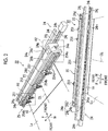
- Figs. 2A and 2B are schematic views showing the overall configuration of the inkjet printing unit according to the first embodiment of the present invention
- Fig. 2A is a perspective view when viewed from rearward (inlet side of the corrugated fiberboard 10) and right obliquely upward
- Fig. 2B is a perspective view when viewed from forward (outlet side of the corrugated fiberboard 10) and obliquely upward.
- Figs. 3A and 3B are schematic views showing a partial configuration of the inkjet printing unit of the first embodiment of the present invention
- Fig. 3A is a perspective view when an A1 portion of Fig. 2A is viewed from rearward and left obliquely
- Fig. 3B is a view when an A2 portion of Fig. 2A is viewed from the front in a state where a rear frame is removed.
- the inkjet printing unit 22 includes an inkjet head (hereinafter, referred to as a head) 23, a head movement unit 24 which moves the head 23, and a pressing unit (protection device) 25 which regulates floating of the corrugated fiberboard 10.
- a head inkjet head
- a head movement unit 24 which moves the head 23
- a pressing unit (protection device) 25 which regulates floating of the corrugated fiberboard 10.
- the head 23 includes multiple inkjet injection ports on a lower surface which faces the corrugated fiberboard 10, and can print a predetermined printing pattern on the corrugated fiberboard 10 by injecting ink from inkjet injection ports positioned at a position corresponding to a printing pattern (variable pattern).
- the head movement unit 24 can move the head 23 up/down and right/left (width direction).
- the head movement unit 24 includes a frame body 24a having open upper portion and lower portion, and the head 23 and the pressing unit 25 are fixed to the frame body 24a.
- the frame body 24a is configured of two parts such as a rear frame 24b and a front frame 24c.
- the front frame 24c is an U shaped frame in a plan view having an open rear side, and in the front frame 24c, a flat plate-shaped front wall portion 24d which extends in the width direction w and side wall portions 24e and 24e which extend from both edges of the front wall portion 24d in the width direction to the rear side are integrally configured.
- the rear frame 24b is a flat plate-shaped frame which extends in the width direction w and is assembled to the rear end surface of both side wall portions 24e of the front frame 24c so as to close the open rear side of the front frame 24c.
- the frame body 24a may be configured of four parts such as the rear frame 24b, the front wall portion 24d, the side wall portion 24e, and the side wall portion 24e.
- nut portions 24m which are positioned so as to close to the end portions of the front frame 24c in the width direction protrude from the front surface of the front frame 24c, and one screw shaft 24i which extends in the width direction W is inserted into the nut portions 24m.
- a pair of rails 24j which extends in parallel to the screw shaft 24i is provided above and below the screw shaft 24i. The rails 24j are laid between a pair of device frames (not shown) and are in contact with the front surface of the front frame 24c.
- the screw shaft 24i is connected to a motor 24k which is fixed to the device frame (not shown), and it is possible to move the head 23 in the width direction W while guiding the head 23 by the rails 24j integrally with the frame body 24a by rotationally driving the screw shaft 24i using the motor 24k.
- brackets 24f protrude from inner wall surfaces of both side wall portions 24e of the frame body 24a, and a motor 24g is fixed to the tip of each of the brackets 24f.
- the motor 24g is connected to the upper portion of a screw shaft 24h which vertically extends and rotationally drives the screw shaft 24h.
- the inkjet head 23 is disposed inside the frame body 24a, and each screw shaft 24h is screwed to each nut portion 23a which protrudes from each of both side surfaces of the inkjet head 23. It is possible to vertically move the head 23 via the nut portion 23a by rotationally driving the screw shaft 24h using the motor 24g.
- the head 23 is fixed to the frame body 24a via the nut portion 23a, the screw shaft 24h, the motor 24g, and the bracket 24f.
- the pressing unit 25 will be described.
- a gap between the ink injection port of the head 23 and a printing surface (the upper surface of the corrugated fiberboard 10, and hereinafter, referred to as a sheet printing surface) of the corrugated fiberboard 10 increases, accuracy of a position (printing position) at which ink is landed on a sheet printing surface decreases. Accordingly, a gap dimension between the lower surface of the head 23 on which the ink injection port is formed and the sheet printing surface is set to a slight dimension (for example, 1mm or more and 5 mm or less).
- the corrugated fiberboard 10 is not fully flat and is bent or corrugated. Accordingly, in the corrugated fiberboard 10, a location which slightly floats from the transport passage Ls is generated. Since the gap dimension between the head 23 and the corrugated fiberboard 10 is a slight dimension, if the floating of the corrugated fiberboard 10 increases, there is a concern that the corrugated fiberboard 10 comes into contact with the head 23 and the ink injection port of the head 23 or the head main body is damaged. Accordingly, the pressing unit 25 is provided so as to regulate approaching of the corrugated fiberboard 10 within a predetermined distance against the head 23 due to the floating of the corrugated fiberboard 10, and contact between the corrugated fiberboard 10 and the ink injection port is prevented.
- the pressing unit 25 is provided on the rear side (upstream side) of the head 23 in the sheet transport direction F in the present embodiment and is installed on the rear surface of the frame body 24a of the head movement unit 24.
- the pressing unit 25 includes multiple pressing roller units (regulation means, regulation part) 251 which are arranged in the width direction w and a mechanism which moves each of the pressing roller units 251 vertically and horizontally.
- each pressing roller unit (hereinafter, referred to as a roller unit) 251 includes a rod 251a which vertically extends, a rotation support member 251b which defines the lower surface of the rod 251a, and a pressing roller 251c which is rotationally supported by the rotation support member 251b.
- the rotation support member 251b is an approximately U-shaped member having an open lower portion, and the pressing roller 251c is rotationally supported inside the U-shaped portion.
- a bracket 251d (hereinafter, referred to as a rod bracket) which is long in the width direction is fixed to the rod 251a.
- the rod bracket 251d is a wide bracket having a width dimension which is larger than the width dimension of the rod 251a and is approximately the same width dimension as that of a movement block 252 described below, and protrudes toward one side (toward the right side in Fig. 3A ) in the width direction from the rod 251a.
- a diameter Dr of the pressing roller 251c is set to be smaller than a diameter Dc (refer to Fig. 1 ) of the plate cylinder 21a of each of the flexographic printing units 21A to 21D.
- the pressing roller 251c uses a roller which prevents the roller from being rubbed to the pattern (ink) of the corrugated fiberboard 10 to pollute the corrugated fiberboard 10 and prevents the corrugated fiberboard 10 from being damaged when the roller comes into contact with the corrugated fiberboard 10.
- the pressing roller 251c is a lightweight roller which is easily rotated according to the movement of the transported corrugated fiberboard 10 when the roller comes into contact with the corrugated fiberboard 10.
- the pressing roller 251c is a roller having the surface which is formed of a soft material, or a so-called potato roller which has an uneven surface and a small contact area even when the roller comes into contact with the corrugated fiberboard 10.
- a sheet guide which has a brush or a guide surface on a low-friction coating is provided may be installed so as to face the transport passage Ls.
- Each of the roller units 251 can move in the width direction W as shown in an arrow X, and can be lifted and lowered (can move forward and rearward against the corrugated fiberboard 10) as shown in an arrow Z. A specific configuration which moves each roller unit 251 in this way will be described.
- Each roller unit 251 is attached to the movement block 252 which can vertically move.
- the movement block 252 includes a block main body 252a having an approximately rectangular parallelepiped shape which is vertically elongated and brackets 252b to 252e which are fixed to the rear surface of the block main body 252a.
- Each of the brackets 252b to 252e is a narrow bracket which is approximately half of the width dimension of the block main body 252a.
- the brackets 252b and 252c are close to the other side (the left side in Fig. 3A ) in the width direction of the block main body 252a, and are juxtaposed above and below the rod bracket 251d. Hole portions which vertically penetrates are provided in the brackets 252b and 252c, and the rod 251a is inserted into the hole portions so as to be vertically moved.
- the brackets 252d and 252e are close to one side (the right side in Fig. 3A ) in the width direction of the block main body 252a, and are juxtaposed above and below the rod bracket 251d. Hole portions which vertically penetrates are provided in the brackets 252d and 252e, and a screw shaft 253b which vertically extends and on which screws are partially formed is rotatably inserted into the hole portions.
- the upper side of the screw shaft 253b is connected to the motor 253a connected to the block main body 252a and the lower side of the screw shaft 253b is screwed to one side (the right side in Fig. 3A ) of the rod bracket 251d in the width direction.
- the screw shaft 253b is rotated by the motor 253a, and the roller unit 251 is lifted and lowered on the screw shaft 252b via the rod bracket 251d. That is, in the movement mechanism which moves the regulation means of the present invention, the function which lifts and lowers the regulation means is configured of the motor 253a, the screw shaft 253b, and the rod bracket 251d.
- screws are partially formed on the screw shaft 253b such that the roller unit 251 can be lifted and lowered by a necessary range. Since screws are not formed on the locations of the screw shaft 253b which are inserted into the brackets 252d and 252e, even when the screw shaft 253b rotates, a force which lifts and lowers the brackets 252d and 252e does not act on the brackets 252d and 252e from the screw shaft 253b. That is, the brackets 252d and 252e are guide brackets.
- a recessed portion 252f is formed on the front surface of the block main body 252a of each movement block 252.
- a hollow motor 254e and a nut 254a which is vertically rotated and driven by the hollow motor 254e are accommodated in the recessed portion 252f.
- a common screw shaft 254b which extends in the width direction W is inserted into and screwed to respective nuts 254a.
- the hollow motor 254e is shown so as to be simplified.
- the screw shaft 254b is behind the rear frame 24b of the frame body 24a.
- a pair of brackets 254c is attached to both edges of the rear surface of the rear frame 24b in the width direction. Both ends of the screw shaft 254b are fixed to the brackets 254c.
- a pair of rails 254d which extends to be parallel to the screw shaft 254b is provided on the rear surface of the rear frame 24b above and below the screw shaft 254b.
- Each of the rails 254d is provided over the entire width of the front frame 24b.
- the rails 254d are slidingly fitted to the front surface of the block main body 252a above and below the recessed portion 252f.
- the roller unit 251 is moved on the screw shaft 254b in the width direction W while being guided on the rails 254d integrally with the movement block 252. That is, in the movement mechanism which moves the regulation means of the present invention, the function which moves the regulation means in the width direction is configured of the hollow motor 254e, the nut 254a, the screw shaft 254b, and the rails 254d.
- the movement block 252 of the roller unit 251 is attached to the frame body 24a of the head movement unit 24 via the nut 254a, the screw shaft 254b, and the bracket 254c. Accordingly, it is possible to move the roller unit 251 integrally with the inkjet head 23 in the width direction W by the head movement unit 24.
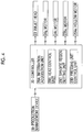
- controller 20 which controls the operation of the inkjet printing unit 22 will be described with reference to Fig. 4 .
- Fig. 4 is a block diagram showing the configuration of the controller of the inkjet printing unit according to the first embodiment of the present invention.
- the controller 20 acquires various order information such as pattern information (ink coverage, pattern, disposition of pattern, or the like) or thickness information (hereinafter, referred to as sheet thickness information) of the corrugated fiberboard 10 from a production management device 50, and controls the operation of the inkjet printing unit 22 based on various order information.
- the controller 20 is configured to include an information acquisition unit (sheet thickness acquisition unit) 20A, an inkjet head control unit (hereinafter, referred to as a head control unit) 20B, a specific column setting unit 20C, and a pressing unit control unit (movement mechanism control unit) 20D.
- the information acquisition unit 20A acquires various order information from the production management device 50.
- the head control unit 20B controls the operation of the motor 24g based on the sheet thickness information acquired from the production management device 50, and moves the head 23 such that the head 23 reaches an appropriate height which is higher than the printing surface of the corrugated fiberboard 10 by a predetermined distance (for example, 1 mm or more and 5 mm or less).
- the head control unit 20B controls the operation of the motor 24g when the inkjet printing unit 22 is stopped or at the time of maintenance of the inkjet printing unit 22 to integrally move the head 23 and the pressing unit 24 so as to be close to one end (move the head and the pressing unit 24 to standby positions).
- the head control unit 20B output a control command to the head 23 based on the pattern information (printing by the inkjet printing unit 22, or disposition of the patterns) acquired from the production management device 50, and prints a predetermined variable pattern on the corrugated fiberboard by injecting ink from the ink injection port positioned at the position corresponding to the pattern to the corrugated fiberboard 10.
- the specific column setting unit 20C acquires a distribution of ink coverage in the sheet width direction W, a creasing location, or a glue application location from the production management device 50 as the order information, and selects the specific column based on the information.
- the specific column is a column which is classified in the sheet width direction W, and is a column in which a printing quality of the corrugated fiberboard 10 is less influenced by the contact between the pressing roller 251c and the corrugated fiberboard 10 even when the pressing roller 251c of the roller unit 251 comes into contact with the corrugated fiberboard 10.
- As a typical specific column there is a margin portion in which the printing pattern does not exist.
- the "ink coverage” means an ink attachment area ratio of the sheet surface on the line in the printing direction. For example, in a case where the entire ink is not attached to a predetermine width column on the printing surface of one corrugated fiberboard 10 in the line in the printing direction, the ink coverage of the width column becomes 0%, and in a case where the entire ink is attached to a width column, the ink coverage of the width column becomes 100%.
- the specific column setting unit 20C sets the number (four locations in the present embodiment) which coincides with the number of roller unit 251 to an upper limit, and sequentially sets the specific column according to the priority level.
- a low ink coverage column (a column in which the ink coverage is 0%, that is, includes a column in which the pattern by the flexographic printing does not exist) is firstly preferentially set (priority level 1), in which the ink coverage (that is, total ink coverage of the flexographic printing units 21A to 21D) Ra_F of the flexographic printing section 21 which performs printing on the upstream of the pressing unit 25 of the inkjet printing unit 22 is a predetermined threshold Ra_Th or less, the glue application location is secondarily preferentially set (priority level 2), and the creasing location is thirdly preferentially set (priority level 3).
- the threshold Ra_Th is appropriately set to be 0% or more, and only the column in which the threshold Ra_Th is set to 0% and the pattern does not exist may be set to the low ink coverage column by the specific column setting unit 20C.
- the creasing location may be preferentially set to the specific column than the glue application location.
- the specific column is a column having a wider width than the width of the pressing roller 251c. This is because if the width of the specific column is narrower than the width of the pressing roller 251c, the pressing roller 251c comes into contact with the corrugated fiberboard 10 at a column deviated from the specific column, and the pressing roller 251c is likely to come into contact with a column having a high ink coverage outside the specific column.
- a location having lower ink coverage is preferentially set to the specific column.
- the specific column setting unit 20C selects the specific columns such that the corrugated fiberboard 10 can equally dispose the specific column in the width direction if necessary (can equally regulate the corrugated fiberboard 10 in the width direction W by the roller units 251 if necessary).
- the pressing unit control unit 20D controls the operation of the hollow motor 254e to appropriately move each roller unit 251 in the width direction W, and each roller unit 251 moves to above the specific column set by the specific column setting unit 20C.
- the pressing unit control unit 20D sets a regulation height, by which the corrugated fiberboard 10 is regulated, based on the sheet thickness information acquired from the production management device 50, and appropriately lifts and lowers each roller unit 251 such that the height of the lower end of the pressure roller becomes the regulation height.
- the regulation height is set to be positioned higher by a predetermined distance L from an ideal printing surface height (this ideal printing surface height becomes the printing surface height in a case where floating of the corrugated fiberboard 10 does not occur and is a height positioned higher by the thickness of the corrugated fiberboard from the sheet transport passage Ls) of the corrugated fiberboard 10.
- the predetermined height L (in order words, is an allowable height even when the corrugated fiberboard 10 floats from the sheet transport passage Ls) is set such that the position of ink landed on the sheet printing surface is not largely deviated, for example, the predetermined height L is 0 mm to 1 mm (0 mm or more and 1 mm or less).
- the predetermined height L is too short, since the pressing unit 25 and the corrugated fiberboard 10 come into frequent contact with each other and the corrugated fiberboard 10 is likely to be polluted or damaged, more preferably, the distance L is 0.5 mm to 1 mm (0.5 mm or more and 1 mm or less).
- the predetermined height L is not limited to the range.
- the pressing unit 25 comes into normal contact with the corrugated fiberboard.
- the pressing unit 25 approximately lightly touches the corrugated fiberboard 10 (so-called kiss touch). Accordingly, compared to the sheet guide of PTL 1 described in the Background Art in which the sheet guide presses the corrugated fiberboard 10, it is possible to prevent the corrugated fiberboard 10 from being polluted or damaged.
- Figs. 5A and 5B are schematic plan views for explaining effects of the present embodiment, and for convenience, the head 23 is indicated by two-dot chain lines, the pressing rollers 251c are indicated by solid lines, and other configurations of the inkjet printing unit 22 are omitted.
- Figs. 5A and 5B chain lines indicate creasing (including creasing which is post-processed by the paper discharge section 3 and the die-cut section 4 positioned on the downstream side of the pressing unit 25), and broken lines indicate groove portions which are formed from now in the paper discharge section 3 or the die-cut section 4.
- Reference numerals 100A-1 to 100A-4 indicate fixed printing by the flexographic printing units 21A to 21D.
- the specific column setting unit 20C virtually classifies the corrugated fiberboard 10 into multiple columns R1 to R9 in the width direction W.
- the column R1 is a column in which the fixed pattern by the flexographic printing does not exist (the ink coverage Ra_F related to the flexographic printing is 0 (zero)).
- the column R2 is a column which includes the fixed pattern 100A-1 by the flexographic printing and in which the ink coverage Ra_F related to the flexographic printing exceeds the threshold value Ra_Th.
- the column R3 is a column which is positioned between the fixed patterns 100A-1 and 100A-2 by the flexographic printing and in which the fixed pattern by the flexographic printing does not exist.
- the column R4 is a column which includes the fixed pattern 100A-2 by the flexographic printing and in which the ink coverage Ra_F related to the flexographic printing exceeds the threshold value Ra_Th.
- the column R5 is a column which is positioned between the fixed patterns 100A-2 and 100A-3 by the flexographic printing and in which the fixed pattern by the flexographic printing does not exist.
- the column R6 is a column which includes the fixed pattern 100A-3 by the flexographic printing and in which the ink coverage Ra_F by the flexographic printing is equal to or less than the threshold value Ra_Th.
- the column R7 is a column in which the fixed pattern by the flexographic printing does not exist.
- the column R8 is a column which includes the fixed pattern 100A-4 by the flexographic printing and in which the ink coverage Ra_F related to the flexographic printing exceeds the threshold Ra_Th.
- the column R9 is a column which includes the glue application location 11 of the corrugated fiberboard 10 and the fixed pattern by the flexographic printing does not exist.
- the specific column setting unit 20C sets the specific columns having the same number as the number of the roller units 251 according to the above-described priority level.
- the columns R1, R7, and R9 (the first priority level) in which the fixed pattern by the flexographic printing does not exist
- the column R6 (the fourth priority level) in which the ink coverage Ra_F by the flexographic printing is equal to or less than the threshold value Ra_Th although the fixed pattern by the flexographic printing exists are set to the specific columns.
- the column R3 is the column which is positioned between the fixed patterns 100A-1 and 100A-2 by the flexographic printing and in which the fixed pattern by the flexographic printing does not exist, the column R3 is excluded from the setting of the specific column based on the ink coverage Ra_F.
- a width dimension W3 of the column R3 is narrower than a width dimension Wr of the pressing roller 251c, and therefore, if the column R3 is set to the specific column and the pressing roller 251c is disposed above the column R3, the pressing roller 251c is disposed on not only the column R3 but also the both columns R2 and R4. That is, this is because the pressing roller 251c is likely to come into contact with the corrugated fiberboard 10 on the columns R2 and R4 in which the ink coverage Ra_F exceeds the threshold Ra_Th. Due to similar reasons, the column R5 is excluded from the setting of the specific column based on the ink coverage Ra_F.
- the pressing unit control unit 20D appropriately moves the respective pressing rollers 251c (roller unit 251) in the width direction such that four pressing rollers 251c respectively move to above the specific columns R1, R6, R7, and R9.
- a wide column in which multiple pressing rollers 251c can be disposed is set to multiple specific columns, and the multiple the pressing rollers 251c may be disposed on the multiple specific columns.
- the glue application location or the creasing location which typically has a lower priority level than that of the low image line column may be preferentially set to the specific column than the low image line column.
- a band-shaped fixed pattern 100A-5 is printed over the entire width by the flexographic printing, and the ink coverage Ra_F related to the flexographic printing exceeds the threshold value Ra_Th over the entire width of the corrugated fiberboard 10.
- the specific column setting unit 20C temporarily selects the glue application location 11 (priority level 1), and the creasing locations 12a, 12b, 12c, and 12d (priority level 2) in which the creasing is formed.
- the specific column setting unit 20C performs selection from among the creasing locations 12a, 12b, 12c, and 12d having a lower priority level such that the corrugated fiberboard 10 can be equally regulated if necessary in the width direction by the roller unit 251.
- the creasing location 12d which is closest to the glue application location 11 which is firstly preferentially set to the specific column is excluded, and the glue application location 11, and the creasing locations 12a, 12b, and 12c are set to the specific columns.
- the column is preferentially selected. Accordingly, as the specific column, that is, as the site at which the position of the corrugated fiberboard 10 is regulated by the roller unit 251, the site in which the pattern by the flexographic printing does not exist is firstly preferentially selected. Therefore, the roller unit 251 regulating the corrugated fiberboard 10 does not pollute the pattern which is not completely fixed to the printing surface of the corrugated fiberboard 10 immediately after the corrugated fiberboard 10 is printed by the flexographic printing section 21.
- the location in which the ink coverage Ra_F is low is selected. Accordingly, even when the floating corrugated fiberboard 10 comes into contact with the roller unit 251 in a case where the roller unit 251 is disposed so as to be separated from the printing surface of the corrugated fiberboard 10, a probability of the corrugated fiberboard 10 coming into contact with the roller unit 251 at the location in which the pattern exists can be decreased.
- the roller unit 251 is disposed so as to comes into constant contact with the sheet printing surface (in a case where a distance L between the sheet printing surface and the pressing roller 251c) is set to 0 mm), the contact area between the roller unit 251 and the pattern is small. Accordingly, it is possible to decrease influences with respect to the printing quality.
- the creasing locations 12a, 12b, 12c, and 12d (hereinafter, referred to as a creasing location 12 in a case of being not specifically classified) or the glue application location 11 is set to the site at which the corrugated fiberboard 10 is regulated.
- the creasing location 12 is a site which becomes a corner portion when the corrugated fiberboard 10 is assembled to form a box shape
- the glue application location 11 is a site at which the corrugated fiberboard 10 is bonded when the corrugated fiberboard 10 becomes the box sheet material 10a.
- the roller unit 251 (pressing roller 251c) is controlled so as to be positioned on the corrugated fiberboard 10. That is, the distance L between the printing surface of the corrugated fiberboard 10 and the pressing roller 251c is set to at least 0 mm. Accordingly, the roller unit 251 is separated from the corrugated fiberboard 10 or is kiss-touched to the corrugated fiberboard 10, and the roller unit 251 does not come into press-contact with corrugated fiberboard 10. Accordingly, compared to a case where the roller unit 251 positively presses the corrugated fiberboard 10, it is possible to reduce a burden imposed on the corrugated fiberboard 10, and it is possible to prevent the corrugated fiberboard 10 from being damaged.
- the pressing roller 251c is disposed so as to be separated from the printing surface of the corrugated fiberboard 10 only when the floating of the corrugated fiberboard 10 increases and the corrugated fiberboard 10 approaches the inkjet head 23 within a predetermined distance, the corrugated fiberboard 10 comes into contact with the pressing roller 251c. Accordingly, since the corrugated fiberboard 10 and the pressing roller 251c do not come into contact with each other at all times, it is possible to prevent the corrugated fiberboard 10 from being polluted or damaged due to the contact between the corrugated fiberboard 10 and the pressing roller 251c.
- roller unit 251 is lifted and lowered according to the thickness of the corrugated fiberboard 10, it is possible to set the height of the roller unit 251 to an optimal height regardless of the thickness of the corrugated fiberboard 10, it is possible to decrease an unnecessary contact between the roller unit 251 and the corrugated fiberboard 10, and it is possible to reliably prevent the corrugated fiberboard 10 from being damaged.
- a corrugated fiberboard printing device of the present embodiment further includes an inkjet printing unit 22A in addition to the flexographic printing section 21 as another printing unit which performs printing on the upstream side of the pressing unit 25.
- the inkjet printing unit 22A is disposed on immediately the upstream side (that is, between the inkjet printing unit 22 and the flexographic printing section 21) of the inkjet printing unit 22.
- the inkjet printing unit 22A performs printing using different colors from those of the inkjet printing unit 22, and the configuration of inkjet printing unit 22A is similar to that of the inkjet printing unit 22.
- the inkjet printing unit 22A is shown so as to be smaller than the inkjet printing unit 22.
- the inkjet printing unit 22A may be provided on the upstream side of the flexographic printing section 21.
- the specific column setting unit 20C (refer to Fig. 4 ) which configures the function of the controller 20 firstly preferentially sets the low ink coverage column in which a total ink coverage Ra_T is the predetermined threshold value Ra_Th or less to the specific column (priority level 1), similarly to the first embodiment, secondarily preferentially sets the glue application location to the specific column (priority level 2), and thirdly preferentially sets the creasing location to the specific column (priority level 3).
- a low ink coverage column in which the total ink coverage Ra_T is the predetermined threshold value Ra_Th or less includes a column in which the total ink coverage Ra_T is 0%, that is, a column in which the pattern by the printing of the flexographic printing section 21 and the pattern by the printing of the inkjet printing unit 22A do not exist.
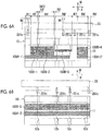
- Figs. 6A and 6B are schematic plan views for explaining effects of the present embodiment, and for convenience, the head 23 is indicated by two-dot chain lines, the pressing rollers 251c are indicated by solid lines, and other configurations of the inkjet printing unit 22 are omitted.
- Figs. 6A and 6B chain lines indicate creasing (including creasing which is post-processed by the paper discharge section 3 and the die-cut section 4 positioned on the downstream side of the pressing unit 25), and broken lines indicate groove portions which are formed from now in the paper discharge section 3 or the die-cut section 4.
- Reference numerals 100A-1' to 100A-3' indicate fixed printing by the flexographic printing units 21A to 21D.
- Reference numerals 100B-1 to 100B-5 indicate variable printing by another inkjet printing unit 22A.
- the specific column setting unit 20C virtually classifies the corrugated fiberboard 10 into multiple columns R1' to R9' in the width direction W.
- the column R1' is a column in which the variable pattern by the printing of the inkjet printing section 22A does not exist (the ink coverage Ra_I related to the inkjet printing 22A is 0 (zero)), which includes the fixed pattern 100A-1' by the flexographic printing, and in which the total ink coverage Ra_T is the threshold Ra_Th or less.
- the column R2' is a column which includes the variable pattern 100B-1 by the printing of the inkjet printing section 22A and the fixed pattern 100A-1' by the flexographic printing and in which the total ink coverage Ra_T exceeds the threshold Ra_Th.
- the column R3' is a column which includes only the fixed pattern 100A-1' by the flexographic printing and in which the total ink coverage Ra_T is the threshold value Ra_Th or less.
- the column R4' is a column which includes the variable pattern 100B-2 by the printing of the inkjet printing section 22A and the fixed pattern 100A-1' by the flexographic printing and in which the total ink coverage Ra_T exceeds the threshold value Ra_Th.
- the column R5' is a column which includes only the fixed pattern 100A-1' by the flexographic printing and in which the total ink coverage Ra_T is the threshold value Ra_Th or less.
- the column R6' is a column which includes the variable pattern 100B-3 by the printing of the inkjet printing section 22A and the fixed pattern 100A-1' by the flexographic printing and in which the total ink coverage Ra_T is the threshold value Ra_Th or less.
- the column R7' is a column in which the variable pattern by the printing of the inkjet printing section 22A and the fixed pattern by the flexographic printing do not exist and the total ink coverage Ra_T is 0 (zero).
- the column R8' is a column which includes the variable pattern 100B-4 by the printing of the inkjet printing section 22A and the fixed pattern 100A-2' by the flexographic printing and in which the total ink coverage Ra_T exceeds the threshold value Ra_Th.
- the column R9' is a column which includes the glue application location 11 of the corrugated fiberboard 10 and in which the variable pattern by the printing of the inkjet printing section 22A and the fixed pattern by the flexographic printing do not exit.
- the specific column setting unit 20C sets the specific columns having the same number as the number of the roller units 251 according to the above-described priority level.
- the columns R7' and R9' (the first priority level) in which the total ink coverage Ra_T is 0 (zero) and the columns R1' and R6' (the fourth priority level) in which the total ink coverage Ra_T is the threshold value Ra_Th or less are set to the specific columns.
- the column R3' is the column in which the total ink coverage Ra_T is the threshold value Ra_Th or less, since the width dimension W3 of the column R3' is narrower than the width dimension Wr of the pressing roller 251c, the column R3' is excluded from the setting of the specific column based on the ink coverage.
- a band-shaped variable pattern 100B-5 is printed over the entire width by the printing of the inkjet printing section 22A and a band-shaped fixed pattern 100A-3' is printed over the entire width by the flexographic printing, and the total ink coverage Ra_T exceeds the threshold value Ra_Th over the entire width of the corrugated fiberboard 10.
- the specific column setting unit 20C temporarily selects the glue application location 11 (priority level 1), and the creasing locations 12a, 12b, 12c, and 12d (priority level 2) in which the creasing is formed.
- the specific column setting unit 20C excludes the creasing location 12d closest to the glue application location 11 which is firstly preferentially set to the specific column and sets the glue application location 11 and the creasing locations 12a, 12b, and 12c to the specific columns such that the corrugated fiberboard 10 can be equally regulated if necessary in the width direction by the roller unit 251.
- correction may be performed by a degree of dryness of ink used in the printing.
- a method of the correction as expressed in the following Expression (1), a method is exemplified which uses ink coverage Ra_F1, Ra_F2, Ra_F3, and Ra_F4 of the flexographic printing units 21A, 21B, 21C, and 21D, the ink coverage Ra_I of the inkjet printing unit 22A, and weighting correction coefficients k1 to k5 which are set by the degree of dryness of ink.
- the ink coverage Ra_F1, Ra_F2, Ra_F3, and Ra_F4 of the flexographic printing units 21A, 21B, 21C, and 21D are amended using correction coefficients k1 to k4 which are set according to the degrees of dryness.
- Total ink coverage Ra_T k 1 ⁇ Ra_F 1 + k 2 ⁇ Ra_F 2 + k 3 ⁇ Ra_F 3 + k 4 ⁇ Ra_F 4 + k 5 ⁇ Ra_I
- the weighting correction coefficients k1 to K5 are set to be smaller as the degree of dryness of ink at the time when the corrugated fiberboard 10 on which the patterns are printed by the flexographic printing units 21A to 21D and the inkjet printing unit 22A reaches the pressing unit 25 increases (as dryness proceeds and a degree of fixation increases).
- the degree of dryness of ink increases as permeability (drying properties) of the ink increases, and increases as the film thickness of ink on the corrugated fiberboard 10 decreases.
- the permeability is high and drying (fixation) is fast, and in the inkjet ink used in the inkjet printing unit 22A, the drying also is fast.
- the degree of dryness of ink increases as an elapse time after the ink on the corrugated fiberboard 10 is longer (in other words, as a parameter which is in a proportional relationship with the elapse time such as the transport distance of the corrugated fiberboard 10 after the ink is attached to the corrugated fiberboard 10 is larger (longer)).
- the weighting correction coefficients k1 to K5 are set to be smaller as the permeability (dry properties) of the ink increases, and are set to be smaller as the elapse time after the ink on the corrugated fiberboard 10 is longer (or, as the parameter which is in a proportional relationship with the elapse time such as the transport distance of the corrugated fiberboard 10 after the ink is attached to the corrugated fiberboard 10 is larger (longer))
- the weighting coefficient is changed according to the kind of the corrugated fiberboard or presence or absence of a drying device in addition of the kind of ink or the elapse time.
- the flexographic ink has higher drying properties than those of the inkjet ink.
- the flexographic printing section 21 is positioned on the upstream side of the inkjet printing unit 22A, the elapse time after the flexographic ink is attached to the corrugated fiberboard 10 at the time when the corrugated fiberboard 10 reaches the pressing unit 25 is longer than the elapse time after the inkjet ink is attached to the corrugated fiberboard 10.
- the weighting correction coefficients k1 to k4 which are multiplied to the ink coverage Ra_F1 to Ra_F4 of the flexographic printing section 21 is set to be smaller than the weighting correction coefficient k5 which is multiplied to the ink coverage Ra_I of the inkjet printing unit 22A.
- the total ink coverage Ra_T of the column is corrected to be smaller, and the column is easily set to the specific column, that is, the location at which the position of the corrugate fiberboard 10 is regulated as the degree of dryness of the ink increases in the column, that is, the printing quality is less decreased in the column even when the column is pressed by the pressing unit 25. Therefore, it is possible to more effectively present the printing quality of the corrugated fiberboard 10 from decreasing.
- the weighting correction coefficients k1 to k4 are set to 0 (zero).
Landscapes
- Engineering & Computer Science (AREA)
- Mechanical Engineering (AREA)
- Business, Economics & Management (AREA)
- Educational Administration (AREA)
- Educational Technology (AREA)
- Making Paper Articles (AREA)
- Ink Jet (AREA)
- Handling Of Cut Paper (AREA)
- Feeding Of Articles By Means Other Than Belts Or Rollers (AREA)
Abstract
Description
- The present invention relates to a corrugated fiberboard printing device which prints a corrugated fiberboard by an inkjet head and a box-making machine having the same.
- In recent years, various devices which print a corrugated fiberboard using an inkjet type printing device have been developed. In the inkjet type printing device, there is a concern that an inkjet head is damaged if the corrugated fiberboard comes into contact with an inkjet head, and it is necessary to maintain a distance between the inkjet head and the printing surface of the corrugated fiberboard to an appropriate range in order to maintain a constant printing quality. However, since the corrugated fiberboard is not fully flat and is bent or corrugated, in the corrugated fiberboard, a location which slightly floats from a sheet transport passage is generated.
- In a case where the inkjet type printing device is applied to the printing of the corrugated fiberboard, it is necessary to prevent the distance between the corrugated fiberboard and the inkjet head from being deviated from an appropriate range (including a contact between the corrugated fiberboard and the inkjet head) due to the floating.
- For example, as a technology which maintains the distance between the printing surface of the corrugated fiberboard and the inkjet head to an appropriate range, there is a technology which is disclosed in
PTL 1. Hereinafter, the technology which is described inPTL 1 is explained. For reference, reference numerals used inPTL 1 are indicated in parentheses. - A box-making machine (1) of a corrugated fiberboard disclosed in PTL 1 (refer to paragraphs [0021] to [0023 and
Figs. 1 to 6 ] includes an inkjet type ink head (30) which injects liquid ink to a corrugated fiberboard (S) and a sheet guide device (46) for maintaining a printing quality so as to hold a gap value between the ink head (30) and the corrugated fiberboard (S) to an optimal gap value (t). - The sheet guide device (46) includes a sheet guide (47) which comes into surface contact with the corrugated fiberboard (S) on at least one of the upstream side and the downstream side of the ink head (30) to reduce micro vibrations of the corrugated fiberboard (S). Preferably, the sheet guide (47) is not only displaced on the corrugated fiberboard (S) simply so as to stabilize the corrugated fiberboard (S) when the printing is performed, but the sheet guide (47) is also slightly pressed to the corrugated fiberboard (S) so as to not substantially collapse the corrugated fiberboard (S).
- [PTL 1] Japanese Unexamined Patent Application Publication No.
2003-231244 - However, in the technology which is disclosed in
PTL 1, since the sheet guide (47) comes into surface contact with the corrugated fiberboard (S), ink is transferred to the sheet guide (47) according to the position of the sheet guide (47), there is a concern that a printed pattern may be polluted, and the corrugated fiberboard is likely to be damaged by the pressurized sheet guide (47). - In addition,
PTL 1 describes that the sheet guide (47) moves in a width direction of the machine according to a printing location. However,PTL 1 does not describe how the sheet guide (47) specifically moves according to the printing location, and inPTL 1, a problem that the sheet guide (47) may pollute the printed pattern is not recognized. - An object of the present invention is to provide a corrugated fiberboard printing device and a box-making machine in which it is possible to prevent the corrugated fiberboard from coming into contact with the inkjet head before the contact occurs while preventing a decrease in a printing quality of the corrugated fiberboard.
-
- (1) In order to achieve the object, according to the present invention, there is provided a corrugated fiberboard printing device which prints a pattern to a corrugated fiberboard which is transported on a transport passage, including: an inkjet head which is disposed above the transport passage and injects ink to the corrugated fiberboard; a protection device which regulates approaching of the corrugated fiberboard within a predetermined distance against the inkjet head; and a controller which acquires order information of the corrugated fiberboard from a production management device and controls the operations of the inkjet head and the protection device, in which the protection device includes multiple regulation means which are juxtaposed in a width direction of the corrugated fiberboard, and a movement mechanism which moves each of the multiple regulation means in the width direction, and the controller includes a specific column setting unit which is set to classify a specific column, in which a printing quality is less influenced even when the specific column is regulated by the regulation means, with respect to the corrugated fiberboard in a sheet width direction based on the order information, and a movement mechanism control unit which controls the operation of the movement mechanism and moves each of the regulation means so as to regulate the corrugated fiberboard in the specific column.
- (2) Preferably, the specific column setting unit sets a low ink coverage column, in which ink coverage is a threshold value or less, to the specific column.
- (3) Preferably, as a column has lower ink coverage, the specific column setting unit preferentially sets the column to the specific column.
- (4) Preferably, the specific column setting unit sets a creasing location at which creasing is formed or a glue application location at which glue is applied to the specific column in a case where the low ink coverage column does not exist or a distribution of the low ink coverage columns is biased.
- (5) Preferably, the specific column setting unit sets a creasing location at which creasing is formed to the specific column.
- (6) Preferably, the specific column setting unit sets a glue application location at which glue is applied to the specific column.
- (7) Preferably, each of the regulation means is a regulation part which is disposed above the transport passage by at least the thickness of the corrugated fiberboard and comes into contact with the corrugated fiberboard to regulate an upward displacement of the corrugated fiberboard.
- (8) Preferably, the regulation part is disposed so as to be separated from the upper surface of the corrugated fiberboard.
- (9) Preferably, the movement mechanism further includes a mechanism which moves the regulation part forward and rearward against the transport passage, the controller includes a sheet thickness acquisition unit which acquires thickness information of the corrugated fiberboard, and the movement mechanism control unit lifts and lowers the regulation part based on the thickness information which is acquired by the sheet thickness acquisition unit.
- (10) Preferably, the specific column setting unit set the specific column using total ink coverage of printing on the upstream side of the regulation part in a transport direction of the corrugated fiberboard as the ink coverage.
- (11) Preferably, the regulation part is provided on the upstream side of the inkjet head in the transport direction and the corrugated fiberboard is printed by one or more other printing units on the upstream side of the regulation part in the transport direction, the specific column setting unit obtains the total ink coverage by summing ink coverage of printing by the one or more other printing units, and when the specific column setting unit obtains the total ink coverage, the specific column setting unit corrects each ink coverage of the printing by the one or more other printing units according to a degree of dryness of each ink on the corrugated fiberboard by the printing of the one or more other printing units.
- (12) Preferably, the regulation part is provided on the downstream side of the inkjet head in the transport direction and the corrugated fiberboard is printed by one or more other printing units on the upstream side of the regulation part in the transport direction, the specific column setting unit obtains the total ink coverage by summing ink coverage of printing by the one or more other printing units and ink coverage of printing by the inkjet head, and when the specific column setting unit obtains the total ink coverage, the specific column setting unit corrects each ink coverage of the printing by the one or more other printing units according to a degree of dryness of ink on the corrugated fiberboard by the printing of the one or more other printing units, and corrects the ink coverage of the printing by the inkjet head according to a degree of dryness of ink on the corrugated fiberboard by the printing of the inkjet head.
- (13) Preferably, the corrugated fiberboard is printed by one or more other printing units on the upstream side of the regulation part in the transport direction, the one or more other printing units have a print cylinder which rotates at the same peripheral speed as a transport speed of the corrugated fiberboard, and the regulation part is a roller which is rotated to be driven by the movement of the transported corrugated fiberboard and has the same diameter as the diameter of the print cylinder.
- (14) Preferably, the inkjet head is provided to face a transport surface of the corrugated fiberboard in a box-making machine, each of the regulation means is configured of an injection device which injects air to the corrugated fiberboard from above, and the specific column setting unit sets the specific column using ink coverage of printing by the inkjet head as the ink coverage.
- (15) In order to achieve the object, according to the present invention, there is provided a box-making machine of a corrugated fiberboard includes the corrugated fiberboard printing device according to any one of (1) to (14) which is provided on the downstream side of the printing unit in a transport direction of the corrugated fiberboard.
- According to the present invention, the specific column, in which a printing quality of the corrugated fiberboard is less influenced, is set based on the order information of the corrugated fiberboard, and approaching of the corrugated fiberboard within the predetermined distance against the inkjet head is regulated in the specific column.
- Accordingly, it is possible to prevent the corrugated fiberboard from coming into contact with the inkjet head before the contact occurs while preventing a decrease in a printing quality of the corrugated fiberboard.
-
-
Fig. 1 is a schematic side view showing a configuration of a box-making machine of a corrugated fiberboard according to a first embodiment of the present invention. -
Figs. 2A and 2B are schematic views showing the overall configuration of an inkjet printing unit according to the first embodiment of the present invention,Fig. 2A is a perspective view when viewed from rearward and right obliquely upward, andFig. 2B is a perspective view when viewed from forward and obliquely upward. -
Figs. 3A and 3B are schematic views showing a partial configuration of the inkjet printing unit of the first embodiment of the present invention,Fig. 3A is a perspective view when an A1 portion ofFig. 2A is viewed from rearward and left obliquely, andFig. 3B is a view when an A2 portion ofFig. 2A is viewed from the front in a state where a rear frame is removed. -
Fig. 4 is a block diagram showing a configuration of a controller of the inkjet printing unit according to the first embodiment of the present invention. -
Figs. 5A and 5B are views for explaining effects of the first embodiment of the present invention, and are schematic plan views showing a corrugated fiberboard and a pressing roller together. -
Figs. 6A and 6B are views for explaining effects of a second embodiment of the present invention, and are schematic plan views showing a corrugated fiberboard and a pressing roller together. - Hereinafter, embodiments of the present invention will be described with reference to the drawings. In addition, each embodiment described below is only an example, and the present invention includes various modifications and technologies which are not described in the following embodiments. Each of configurations of the following embodiments can be exemplified so as to be variously modified within the scope which does not depart from the gist, and the configurations can be appropriately selected or appropriately combined.
- In the following descriptions, a direction in which a corrugated fiberboard is transported in a box-making machine is referred to as a transport direction F or a sheet transport direction F, a direction orthogonal to the transport direction F is referred to as a width direction W, a sheet width direction W, or a horizontal direction W. In addition, a side toward a center CL in the width direction of the corrugated fiberboard is referred to an inner side, and conversely, a side which is away from the center CL in the width direction is referred to an outer side.
- In a case where it is not specifically described, an upstream means the upstream in the transport direction, and similarly, in a case where it is not specifically described, a downstream means the downstream in the transport direction F.
- In a case where it is not specifically described, a front side or a front surface means the downstream side in the transport direction F, and similarly, in a case where it is not specifically described, a rear side or a rear surface means the upstream side in the transport direction F.
- First, the configuration of the box-making machine according to the present embodiment will be described.
- In
Fig. 1 , a process in which a corrugated fiberboard is processed to a sheet-like corrugated box is divided according to device configurations so as to be associated with the device configurations above the device configurations of each process of the box-making machine. As shown inFig. 1 , in the box-making machine, apaper feed section 1, aprinting section 2, apaper discharge section 3, a die-cut section 4, a folder-gluer section 5, and acounter-ejector section 6 are provided in this order from the upstream side. - In the
paper feed section 1, multiple plate-shapedcorrugated fiberboards 10 are carried in a state where thecorrugated fiberboards 10 are stacked, and thecorrugated fiberboards 10 are supplied (fed) to theprinting section 2 one by one. - In the
printing section 2, a pattern is printed to thecorrugated fiberboard 10 which is transported by atransport conveyor 7 one by one. In theprinting section 2, flexographic printing unit (other printing units) 21A to 21D having a predetermined number of colors (here, four colors) are provided above a transport passage (hereinafter, referred to as a sheet transport passage) Ls of thecorrugated fiberboard 10, and aninkjet printing unit 22 is provide above the sheet transport passage Ls on the downstream sides of theflexographic printing units 21A to 21D (hereinafter, theflexographic printing units 21A to 21D are collectively referred to as a flexographic printing section 21). - The
flexographic printing units 21A to 21D sequentially perform printing on thecorrugated fiberboard 10 by ink of each color, and each of theflexographic printing units 21A to 21D includes a plate cylinder (print cylinder) 21a on which a printing table to which flexographic ink is transferred mounted and a receivingroll 21b which causes thecorrugated fiberboard 10 to come into pressure-contact with theplate cylinder 21a, and prints a print image formed on the printing plate, that is, a fixed pattern (hereinafter, referred to as a fixed pattern) 100A on thecorrugated fiberboard 10. - Diameters Dc of the
plate cylinders 21a of theflexographic printing units 21A to 21D are set to be the same as each other, and each of theflexographic printing units 21A to 21D rotates at the same peripheral speed as a transport speed of thecorrugated fiberboard 10 during printing. - The
inkjet printing unit 22 prints a pattern (hereinafter, referred to as a variable pattern) 100B which is changed for each sheet or every a plurality of sheets on thecorrugated fiberboard 10 based on a digital source. Theinkjet printing unit 22 configures the corrugated fiberboard printing device of the present invention along with acontroller 20 described below which controls theinkjet printing unit 22. - In the
paper discharge section 3, grooving or a creasing formation is performed on thecorrugated fiberboard 10 printed by theprinting section 2, and thecorrugated fiberboard 10 is discharged. - In the die-
cut section 4, drilling is performed on thecorrugated fiberboard 10 discharged from thepaper discharge section 3 or grooving or a creasing formation is further performed on thecorrugated fiberboard 10. - In the folder-
gluer section 5, glue is applied to one end in a horizontal direction W of thecorrugated fiberboard 10 processed by the die-cut section 4, and bending is performed such that both right and left end portion of thecorrugated fiberboard 10 overlap each other on the rear side (lower side). Both right and left end portions of thecorrugated fiberboard 10 processed in the folder-gluer section 5 are bonded to each other by glue, and a sheet-like corrugated box (box sheet material) 10a is formed. - In the
counter-ejector section 6, thebox sheet materials 10a processed in the folder-gluer section 5 are placed on a table (stacker table) while being countered. If a predetermined number ofbox sheet materials 10a are stacked in thecounter-ejector section 6, asheet material group 10b is shipped as a batch of one unit. - The
inkjet printing unit 22 will be described with reference toFigs. 2A, 2B ,3A, and 3B . -
Figs. 2A and 2B are schematic views showing the overall configuration of the inkjet printing unit according to the first embodiment of the present invention,Fig. 2A is a perspective view when viewed from rearward (inlet side of the corrugated fiberboard 10) and right obliquely upward, andFig. 2B is a perspective view when viewed from forward (outlet side of the corrugated fiberboard 10) and obliquely upward. -
Figs. 3A and 3B are schematic views showing a partial configuration of the inkjet printing unit of the first embodiment of the present invention,Fig. 3A is a perspective view when an A1 portion ofFig. 2A is viewed from rearward and left obliquely, andFig. 3B is a view when an A2 portion ofFig. 2A is viewed from the front in a state where a rear frame is removed. - As shown in
Figs. 2A and 2B , theinkjet printing unit 22 includes an inkjet head (hereinafter, referred to as a head) 23, ahead movement unit 24 which moves thehead 23, and a pressing unit (protection device) 25 which regulates floating of thecorrugated fiberboard 10. - The
head 23 includes multiple inkjet injection ports on a lower surface which faces thecorrugated fiberboard 10, and can print a predetermined printing pattern on thecorrugated fiberboard 10 by injecting ink from inkjet injection ports positioned at a position corresponding to a printing pattern (variable pattern). - The
head movement unit 24 can move thehead 23 up/down and right/left (width direction). Thehead movement unit 24 includes aframe body 24a having open upper portion and lower portion, and thehead 23 and thepressing unit 25 are fixed to theframe body 24a. - The
frame body 24a is configured of two parts such as arear frame 24b and afront frame 24c. Thefront frame 24c is an U shaped frame in a plan view having an open rear side, and in thefront frame 24c, a flat plate-shapedfront wall portion 24d which extends in the width direction w andside wall portions front wall portion 24d in the width direction to the rear side are integrally configured. Therear frame 24b is a flat plate-shaped frame which extends in the width direction w and is assembled to the rear end surface of bothside wall portions 24e of thefront frame 24c so as to close the open rear side of thefront frame 24c. In addition, theframe body 24a may be configured of four parts such as therear frame 24b, thefront wall portion 24d, theside wall portion 24e, and theside wall portion 24e. - As shown in Fig. 28,
nut portions 24m which are positioned so as to close to the end portions of thefront frame 24c in the width direction protrude from the front surface of thefront frame 24c, and onescrew shaft 24i which extends in the width direction W is inserted into thenut portions 24m. A pair ofrails 24j which extends in parallel to thescrew shaft 24i is provided above and below thescrew shaft 24i. Therails 24j are laid between a pair of device frames (not shown) and are in contact with the front surface of thefront frame 24c. - The
screw shaft 24i is connected to amotor 24k which is fixed to the device frame (not shown), and it is possible to move thehead 23 in the width direction W while guiding thehead 23 by therails 24j integrally with theframe body 24a by rotationally driving thescrew shaft 24i using themotor 24k. - As shown in
Fig. 3B ,brackets 24f protrude from inner wall surfaces of bothside wall portions 24e of theframe body 24a, and amotor 24g is fixed to the tip of each of thebrackets 24f. Themotor 24g is connected to the upper portion of ascrew shaft 24h which vertically extends and rotationally drives thescrew shaft 24h. Theinkjet head 23 is disposed inside theframe body 24a, and eachscrew shaft 24h is screwed to eachnut portion 23a which protrudes from each of both side surfaces of theinkjet head 23. It is possible to vertically move thehead 23 via thenut portion 23a by rotationally driving thescrew shaft 24h using themotor 24g. - In addition, the
head 23 is fixed to theframe body 24a via thenut portion 23a, thescrew shaft 24h, themotor 24g, and thebracket 24f. - The
pressing unit 25 will be described. As a gap between the ink injection port of thehead 23 and a printing surface (the upper surface of thecorrugated fiberboard 10, and hereinafter, referred to as a sheet printing surface) of thecorrugated fiberboard 10 increases, accuracy of a position (printing position) at which ink is landed on a sheet printing surface decreases. Accordingly, a gap dimension between the lower surface of thehead 23 on which the ink injection port is formed and the sheet printing surface is set to a slight dimension (for example, 1mm or more and 5 mm or less). - As described in the Background Art, the
corrugated fiberboard 10 is not fully flat and is bent or corrugated. Accordingly, in thecorrugated fiberboard 10, a location which slightly floats from the transport passage Ls is generated. Since the gap dimension between thehead 23 and thecorrugated fiberboard 10 is a slight dimension, if the floating of thecorrugated fiberboard 10 increases, there is a concern that thecorrugated fiberboard 10 comes into contact with thehead 23 and the ink injection port of thehead 23 or the head main body is damaged. Accordingly, thepressing unit 25 is provided so as to regulate approaching of thecorrugated fiberboard 10 within a predetermined distance against thehead 23 due to the floating of thecorrugated fiberboard 10, and contact between thecorrugated fiberboard 10 and the ink injection port is prevented. - As shown in
Figs. 2A and 2B , thepressing unit 25 is provided on the rear side (upstream side) of thehead 23 in the sheet transport direction F in the present embodiment and is installed on the rear surface of theframe body 24a of thehead movement unit 24. In addition, thepressing unit 25 includes multiple pressing roller units (regulation means, regulation part) 251 which are arranged in the width direction w and a mechanism which moves each of thepressing roller units 251 vertically and horizontally. - As shown in
Fig. 3A , each pressing roller unit (hereinafter, referred to as a roller unit) 251 includes a rod 251a which vertically extends, arotation support member 251b which defines the lower surface of the rod 251a, and apressing roller 251c which is rotationally supported by therotation support member 251b. Therotation support member 251b is an approximately U-shaped member having an open lower portion, and thepressing roller 251c is rotationally supported inside the U-shaped portion. Abracket 251d (hereinafter, referred to as a rod bracket) which is long in the width direction is fixed to the rod 251a. Therod bracket 251d is a wide bracket having a width dimension which is larger than the width dimension of the rod 251a and is approximately the same width dimension as that of amovement block 252 described below, and protrudes toward one side (toward the right side inFig. 3A ) in the width direction from the rod 251a. - In a present embodiment, a diameter Dr of the
pressing roller 251c is set to be smaller than a diameter Dc (refer toFig. 1 ) of theplate cylinder 21a of each of theflexographic printing units 21A to 21D. In addition, preferably, thepressing roller 251c uses a roller which prevents the roller from being rubbed to the pattern (ink) of thecorrugated fiberboard 10 to pollute thecorrugated fiberboard 10 and prevents thecorrugated fiberboard 10 from being damaged when the roller comes into contact with thecorrugated fiberboard 10. Specifically, preferably, thepressing roller 251c is a lightweight roller which is easily rotated according to the movement of the transportedcorrugated fiberboard 10 when the roller comes into contact with thecorrugated fiberboard 10. In addition, preferably, thepressing roller 251c is a roller having the surface which is formed of a soft material, or a so-called potato roller which has an uneven surface and a small contact area even when the roller comes into contact with thecorrugated fiberboard 10. In addition, instead of thepressing roller 251c, a sheet guide which has a brush or a guide surface on a low-friction coating is provided may be installed so as to face the transport passage Ls. - Each of the
roller units 251 can move in the width direction W as shown in an arrow X, and can be lifted and lowered (can move forward and rearward against the corrugated fiberboard 10) as shown in an arrow Z. A specific configuration which moves eachroller unit 251 in this way will be described. - Each
roller unit 251 is attached to themovement block 252 which can vertically move. Themovement block 252 includes a blockmain body 252a having an approximately rectangular parallelepiped shape which is vertically elongated andbrackets 252b to 252e which are fixed to the rear surface of the blockmain body 252a. Each of thebrackets 252b to 252e is a narrow bracket which is approximately half of the width dimension of the blockmain body 252a. - The
brackets Fig. 3A ) in the width direction of the blockmain body 252a, and are juxtaposed above and below therod bracket 251d. Hole portions which vertically penetrates are provided in thebrackets - The
brackets Fig. 3A ) in the width direction of the blockmain body 252a, and are juxtaposed above and below therod bracket 251d. Hole portions which vertically penetrates are provided in thebrackets screw shaft 253b which vertically extends and on which screws are partially formed is rotatably inserted into the hole portions. - In addition, the upper side of the
screw shaft 253b is connected to themotor 253a connected to the blockmain body 252a and the lower side of thescrew shaft 253b is screwed to one side (the right side inFig. 3A ) of therod bracket 251d in the width direction. According to this configuration, if thescrew shaft 253b is rotated by themotor 253a, and theroller unit 251 is lifted and lowered on thescrew shaft 252b via therod bracket 251d. That is, in the movement mechanism which moves the regulation means of the present invention, the function which lifts and lowers the regulation means is configured of themotor 253a, thescrew shaft 253b, and therod bracket 251d. - In addition, screws are partially formed on the
screw shaft 253b such that theroller unit 251 can be lifted and lowered by a necessary range. Since screws are not formed on the locations of thescrew shaft 253b which are inserted into thebrackets screw shaft 253b rotates, a force which lifts and lowers thebrackets brackets screw shaft 253b. That is, thebrackets - A recessed
portion 252f is formed on the front surface of the blockmain body 252a of eachmovement block 252. Ahollow motor 254e and anut 254a which is vertically rotated and driven by thehollow motor 254e are accommodated in the recessedportion 252f. Acommon screw shaft 254b which extends in the width direction W is inserted into and screwed torespective nuts 254a. In addition, inFig. 3A , thehollow motor 254e is shown so as to be simplified. - The
screw shaft 254b is behind therear frame 24b of theframe body 24a. A pair ofbrackets 254c is attached to both edges of the rear surface of therear frame 24b in the width direction. Both ends of thescrew shaft 254b are fixed to thebrackets 254c. - In addition, a pair of
rails 254d which extends to be parallel to thescrew shaft 254b is provided on the rear surface of therear frame 24b above and below thescrew shaft 254b. Each of therails 254d is provided over the entire width of thefront frame 24b. Therails 254d are slidingly fitted to the front surface of the blockmain body 252a above and below the recessedportion 252f. - According to this configuration, if the
nut 254a is rotationally driven by thehollow motor 254e of themovement block 252, theroller unit 251 is moved on thescrew shaft 254b in the width direction W while being guided on therails 254d integrally with themovement block 252. That is, in the movement mechanism which moves the regulation means of the present invention, the function which moves the regulation means in the width direction is configured of thehollow motor 254e, thenut 254a, thescrew shaft 254b, and therails 254d. - In addition, the
movement block 252 of theroller unit 251 is attached to theframe body 24a of thehead movement unit 24 via thenut 254a, thescrew shaft 254b, and thebracket 254c. Accordingly, it is possible to move theroller unit 251 integrally with theinkjet head 23 in the width direction W by thehead movement unit 24. - The configuration of the
controller 20 which controls the operation of theinkjet printing unit 22 will be described with reference toFig. 4 . -
Fig. 4 is a block diagram showing the configuration of the controller of the inkjet printing unit according to the first embodiment of the present invention. - The
controller 20 acquires various order information such as pattern information (ink coverage, pattern, disposition of pattern, or the like) or thickness information (hereinafter, referred to as sheet thickness information) of thecorrugated fiberboard 10 from aproduction management device 50, and controls the operation of theinkjet printing unit 22 based on various order information. As shown inFig. 4 , thecontroller 20 is configured to include an information acquisition unit (sheet thickness acquisition unit) 20A, an inkjet head control unit (hereinafter, referred to as a head control unit) 20B, a specificcolumn setting unit 20C, and a pressing unit control unit (movement mechanism control unit) 20D. - The
information acquisition unit 20A acquires various order information from theproduction management device 50. - The
head control unit 20B controls the operation of themotor 24g based on the sheet thickness information acquired from theproduction management device 50, and moves thehead 23 such that thehead 23 reaches an appropriate height which is higher than the printing surface of thecorrugated fiberboard 10 by a predetermined distance (for example, 1 mm or more and 5 mm or less). - In addition, if an operation switch (not shown) is operated, or automatically, the
head control unit 20B controls the operation of themotor 24g when theinkjet printing unit 22 is stopped or at the time of maintenance of theinkjet printing unit 22 to integrally move thehead 23 and thepressing unit 24 so as to be close to one end (move the head and thepressing unit 24 to standby positions). - In addition, the
head control unit 20B output a control command to thehead 23 based on the pattern information (printing by theinkjet printing unit 22, or disposition of the patterns) acquired from theproduction management device 50, and prints a predetermined variable pattern on the corrugated fiberboard by injecting ink from the ink injection port positioned at the position corresponding to the pattern to thecorrugated fiberboard 10. - The specific
column setting unit 20C acquires a distribution of ink coverage in the sheet width direction W, a creasing location, or a glue application location from theproduction management device 50 as the order information, and selects the specific column based on the information. Here, the specific column is a column which is classified in the sheet width direction W, and is a column in which a printing quality of thecorrugated fiberboard 10 is less influenced by the contact between thepressing roller 251c and thecorrugated fiberboard 10 even when thepressing roller 251c of theroller unit 251 comes into contact with thecorrugated fiberboard 10. As a typical specific column, there is a margin portion in which the printing pattern does not exist. - In addition, the "ink coverage" means an ink attachment area ratio of the sheet surface on the line in the printing direction. For example, in a case where the entire ink is not attached to a predetermine width column on the printing surface of one
corrugated fiberboard 10 in the line in the printing direction, the ink coverage of the width column becomes 0%, and in a case where the entire ink is attached to a width column, the ink coverage of the width column becomes 100%. - Specifically, the specific
column setting unit 20C sets the number (four locations in the present embodiment) which coincides with the number ofroller unit 251 to an upper limit, and sequentially sets the specific column according to the priority level. In the specific column, a low ink coverage column (a column in which the ink coverage is 0%, that is, includes a column in which the pattern by the flexographic printing does not exist) is firstly preferentially set (priority level 1), in which the ink coverage (that is, total ink coverage of theflexographic printing units 21A to 21D) Ra_F of theflexographic printing section 21 which performs printing on the upstream of thepressing unit 25 of theinkjet printing unit 22 is a predetermined threshold Ra_Th or less, the glue application location is secondarily preferentially set (priority level 2), and the creasing location is thirdly preferentially set (priority level 3). - In addition, the threshold Ra_Th is appropriately set to be 0% or more, and only the column in which the threshold Ra_Th is set to 0% and the pattern does not exist may be set to the low ink coverage column by the specific
column setting unit 20C. In addition, the creasing location may be preferentially set to the specific column than the glue application location. - In a case where the low ink coverage column is set to the specific column, it is assumed that the specific column is a column having a wider width than the width of the
pressing roller 251c. This is because if the width of the specific column is narrower than the width of thepressing roller 251c, thepressing roller 251c comes into contact with thecorrugated fiberboard 10 at a column deviated from the specific column, and thepressing roller 251c is likely to come into contact with a column having a high ink coverage outside the specific column. - In a case where there are multiple low ink coverage columns, a location having lower ink coverage is preferentially set to the specific column.
- In addition, since the
corrugated fiberboard 10 include multiple locations having the same priority level as each other, in a case where the specific columns cannot be narrowed to match the number (four locations in the present embodiment) of theroller units 251 by only the priority level (for example, in a case where the number of the margin portions is five or more), the specificcolumn setting unit 20C selects the specific columns such that thecorrugated fiberboard 10 can equally dispose the specific column in the width direction if necessary (can equally regulate thecorrugated fiberboard 10 in the width direction W by theroller units 251 if necessary). - The pressing
unit control unit 20D controls the operation of thehollow motor 254e to appropriately move eachroller unit 251 in the width direction W, and eachroller unit 251 moves to above the specific column set by the specificcolumn setting unit 20C. - In addition, the pressing
unit control unit 20D sets a regulation height, by which thecorrugated fiberboard 10 is regulated, based on the sheet thickness information acquired from theproduction management device 50, and appropriately lifts and lowers eachroller unit 251 such that the height of the lower end of the pressure roller becomes the regulation height. - The regulation height is set to be positioned higher by a predetermined distance L from an ideal printing surface height (this ideal printing surface height becomes the printing surface height in a case where floating of the
corrugated fiberboard 10 does not occur and is a height positioned higher by the thickness of the corrugated fiberboard from the sheet transport passage Ls) of thecorrugated fiberboard 10. - Preferably, the predetermined height L (in order words, is an allowable height even when the
corrugated fiberboard 10 floats from the sheet transport passage Ls) is set such that the position of ink landed on the sheet printing surface is not largely deviated, for example, the predetermined height L is 0 mm to 1 mm (0 mm or more and 1 mm or less). In addition, if the predetermined height L is too short, since thepressing unit 25 and thecorrugated fiberboard 10 come into frequent contact with each other and thecorrugated fiberboard 10 is likely to be polluted or damaged, more preferably, the distance L is 0.5 mm to 1 mm (0.5 mm or more and 1 mm or less). Of course, the predetermined height L is not limited to the range. - In addition, in a case where the predetermined height L is 0 mm, the
pressing unit 25 comes into normal contact with the corrugated fiberboard. However, thepressing unit 25 approximately lightly touches the corrugated fiberboard 10 (so-called kiss touch). Accordingly, compared to the sheet guide ofPTL 1 described in the Background Art in which the sheet guide presses thecorrugated fiberboard 10, it is possible to prevent thecorrugated fiberboard 10 from being polluted or damaged. - Effects of the present embodiment will be described with reference to
Figs. 5A and 5B . -
Figs. 5A and 5B are schematic plan views for explaining effects of the present embodiment, and for convenience, thehead 23 is indicated by two-dot chain lines, thepressing rollers 251c are indicated by solid lines, and other configurations of theinkjet printing unit 22 are omitted. - In
Figs. 5A and 5B , chain lines indicate creasing (including creasing which is post-processed by thepaper discharge section 3 and the die-cut section 4 positioned on the downstream side of the pressing unit 25), and broken lines indicate groove portions which are formed from now in thepaper discharge section 3 or the die-cut section 4.Reference numerals 100A-1 to 100A-4 indicate fixed printing by theflexographic printing units 21A to 21D. - First, if the example shown in
Fig. 5A is described, the specificcolumn setting unit 20C virtually classifies thecorrugated fiberboard 10 into multiple columns R1 to R9 in the width direction W. - The column R1 is a column in which the fixed pattern by the flexographic printing does not exist (the ink coverage Ra_F related to the flexographic printing is 0 (zero)).
- The column R2 is a column which includes the fixed
pattern 100A-1 by the flexographic printing and in which the ink coverage Ra_F related to the flexographic printing exceeds the threshold value Ra_Th. - The column R3 is a column which is positioned between the
fixed patterns 100A-1 and 100A-2 by the flexographic printing and in which the fixed pattern by the flexographic printing does not exist. - The column R4 is a column which includes the fixed
pattern 100A-2 by the flexographic printing and in which the ink coverage Ra_F related to the flexographic printing exceeds the threshold value Ra_Th. - The column R5 is a column which is positioned between the
fixed patterns 100A-2 and 100A-3 by the flexographic printing and in which the fixed pattern by the flexographic printing does not exist. - The column R6 is a column which includes the fixed
pattern 100A-3 by the flexographic printing and in which the ink coverage Ra_F by the flexographic printing is equal to or less than the threshold value Ra_Th. - The column R7 is a column in which the fixed pattern by the flexographic printing does not exist.
- The column R8 is a column which includes the fixed
pattern 100A-4 by the flexographic printing and in which the ink coverage Ra_F related to the flexographic printing exceeds the threshold Ra_Th. - The column R9 is a column which includes the
glue application location 11 of thecorrugated fiberboard 10 and the fixed pattern by the flexographic printing does not exist. - In addition, the specific
column setting unit 20C sets the specific columns having the same number as the number of theroller units 251 according to the above-described priority level. In the example shown inFig. 5A , in a descending order of priority levels, the columns R1, R7, and R9 (the first priority level) in which the fixed pattern by the flexographic printing does not exist, and the column R6 (the fourth priority level) in which the ink coverage Ra_F by the flexographic printing is equal to or less than the threshold value Ra_Th although the fixed pattern by the flexographic printing exists are set to the specific columns. - In addition, although the column R3 is the column which is positioned between the
fixed patterns 100A-1 and 100A-2 by the flexographic printing and in which the fixed pattern by the flexographic printing does not exist, the column R3 is excluded from the setting of the specific column based on the ink coverage Ra_F. - This is because a width dimension W3 of the column R3 is narrower than a width dimension Wr of the
pressing roller 251c, and therefore, if the column R3 is set to the specific column and thepressing roller 251c is disposed above the column R3, thepressing roller 251c is disposed on not only the column R3 but also the both columns R2 and R4. That is, this is because thepressing roller 251c is likely to come into contact with thecorrugated fiberboard 10 on the columns R2 and R4 in which the ink coverage Ra_F exceeds the threshold Ra_Th. Due to similar reasons, the column R5 is excluded from the setting of the specific column based on the ink coverage Ra_F. - In addition, the pressing
unit control unit 20D appropriately moves the respectivepressing rollers 251c (roller unit 251) in the width direction such that fourpressing rollers 251c respectively move to above the specific columns R1, R6, R7, and R9. - In addition, like the column R6, a wide column in which multiple
pressing rollers 251c can be disposed is set to multiple specific columns, and the multiple thepressing rollers 251c may be disposed on the multiple specific columns. - Moreover, since the a low image line column is positioned on only one side of the
corrugated fiberboard 10, in a case where the specific column is set to be deviated toward one side of thecorrugated fiberboard 10, it is difficult to prevent thecorrugated fiberboard 10 from floating over the entire width. In this case, in order to equally suppress thecorrugated fiberboard 10 over the entire width, the glue application location or the creasing location which typically has a lower priority level than that of the low image line column may be preferentially set to the specific column than the low image line column. - Next, the example shown in
Fig. 5B will be described. In this example, a band-shapedfixed pattern 100A-5 is printed over the entire width by the flexographic printing, and the ink coverage Ra_F related to the flexographic printing exceeds the threshold value Ra_Th over the entire width of thecorrugated fiberboard 10. Accordingly, according to the above-described priority level, in a descending order of priority levels, the specificcolumn setting unit 20C temporarily selects the glue application location 11 (priority level 1), and thecreasing locations roller units 251, the specificcolumn setting unit 20C performs selection from among the creasinglocations corrugated fiberboard 10 can be equally regulated if necessary in the width direction by theroller unit 251. Here, the creasinglocation 12d which is closest to theglue application location 11 which is firstly preferentially set to the specific column is excluded, and theglue application location 11, and thecreasing locations - Therefore, the following advantages are obtained according to the present embodiment. As the specific column in which a printing quality of the
corrugated fiberboard 10 is less influenced, as a column has lower ink coverage Ra_F, the column is preferentially selected. Accordingly, as the specific column, that is, as the site at which the position of thecorrugated fiberboard 10 is regulated by theroller unit 251, the site in which the pattern by the flexographic printing does not exist is firstly preferentially selected. Therefore, theroller unit 251 regulating thecorrugated fiberboard 10 does not pollute the pattern which is not completely fixed to the printing surface of thecorrugated fiberboard 10 immediately after thecorrugated fiberboard 10 is printed by theflexographic printing section 21. - Accordingly, it is possible to prevent the
corrugated fiberboard 10 from coming into contact with the inkjet head by theroller unit 251 before the contact occurs while favorably maintaining the printing quality of thecorrugated fiberboard 10. - In addition, even in the case where the printing by the
flexographic printing section 21 is positioned over the entire width of thecorrugated fiberboard 10, as the specific column, the location in which the ink coverage Ra_F is low, that is, the location in which an ink attachment area ratio is low is selected. Accordingly, even when the floatingcorrugated fiberboard 10 comes into contact with theroller unit 251 in a case where theroller unit 251 is disposed so as to be separated from the printing surface of thecorrugated fiberboard 10, a probability of thecorrugated fiberboard 10 coming into contact with theroller unit 251 at the location in which the pattern exists can be decreased. In addition, even in a case where theroller unit 251 is disposed so as to comes into constant contact with the sheet printing surface (in a case where a distance L between the sheet printing surface and thepressing roller 251c) is set to 0 mm), the contact area between theroller unit 251 and the pattern is small. Accordingly, it is possible to decrease influences with respect to the printing quality. - In addition, in a case where the low ink coverage column in which the ink coverage Ra_F is lower than the threshold value Ra_Th does not exist and in a case where the distribution of the low ink coverage columns is deviated and the
corrugated fiberboard 10 cannot be uniformly regulated, the creasinglocations glue application location 11 is set to the site at which thecorrugated fiberboard 10 is regulated. The creasing location 12 is a site which becomes a corner portion when thecorrugated fiberboard 10 is assembled to form a box shape, and theglue application location 11 is a site at which thecorrugated fiberboard 10 is bonded when thecorrugated fiberboard 10 becomes thebox sheet material 10a. - Therefore, even when the creasing location 12 or the
glue application location 11 is regulated by theroller unit 251 and the pattern is polluted, since the creasing location 12 or theglue application location 11 is a site which is not seen or cannot be seen, it is possible to maintain the printing quality of thecorrugated fiberboard 10. - In addition, in general, since the creasing location 12 or the
glue application location 11 exist in thecorrugated fiberboard 10, it is possible to reliably set the specific column even in the case where the low ink coverage column does not exist. - Moreover, the following advantages are obtained by the present embodiment.
- The roller unit 251 (pressing
roller 251c) is controlled so as to be positioned on thecorrugated fiberboard 10. That is, the distance L between the printing surface of thecorrugated fiberboard 10 and thepressing roller 251c is set to at least 0 mm. Accordingly, theroller unit 251 is separated from thecorrugated fiberboard 10 or is kiss-touched to thecorrugated fiberboard 10, and theroller unit 251 does not come into press-contact withcorrugated fiberboard 10. Accordingly, compared to a case where theroller unit 251 positively presses thecorrugated fiberboard 10, it is possible to reduce a burden imposed on thecorrugated fiberboard 10, and it is possible to prevent thecorrugated fiberboard 10 from being damaged. - Particularly, in a case where the
pressing roller 251c is disposed so as to be separated from the printing surface of thecorrugated fiberboard 10, only when the floating of thecorrugated fiberboard 10 increases and thecorrugated fiberboard 10 approaches theinkjet head 23 within a predetermined distance, thecorrugated fiberboard 10 comes into contact with thepressing roller 251c. Accordingly, since thecorrugated fiberboard 10 and thepressing roller 251c do not come into contact with each other at all times, it is possible to prevent thecorrugated fiberboard 10 from being polluted or damaged due to the contact between thecorrugated fiberboard 10 and thepressing roller 251c. - Moreover, since the
roller unit 251 is lifted and lowered according to the thickness of thecorrugated fiberboard 10, it is possible to set the height of theroller unit 251 to an optimal height regardless of the thickness of thecorrugated fiberboard 10, it is possible to decrease an unnecessary contact between theroller unit 251 and thecorrugated fiberboard 10, and it is possible to reliably prevent thecorrugated fiberboard 10 from being damaged. - With respect to the first embodiment, as shown by a two-dot chain line, a corrugated fiberboard printing device of the present embodiment further includes an inkjet printing unit 22A in addition to the
flexographic printing section 21 as another printing unit which performs printing on the upstream side of thepressing unit 25. The inkjet printing unit 22A is disposed on immediately the upstream side (that is, between theinkjet printing unit 22 and the flexographic printing section 21) of theinkjet printing unit 22. - The inkjet printing unit 22A performs printing using different colors from those of the
inkjet printing unit 22, and the configuration of inkjet printing unit 22A is similar to that of theinkjet printing unit 22. InFig. 1 , for convenience, the inkjet printing unit 22A is shown so as to be smaller than theinkjet printing unit 22. In addition, the inkjet printing unit 22A may be provided on the upstream side of theflexographic printing section 21. - In the present embodiment, the specific
column setting unit 20C (refer toFig. 4 ) which configures the function of thecontroller 20 firstly preferentially sets the low ink coverage column in which a total ink coverage Ra_T is the predetermined threshold value Ra_Th or less to the specific column (priority level 1), similarly to the first embodiment, secondarily preferentially sets the glue application location to the specific column (priority level 2), and thirdly preferentially sets the creasing location to the specific column (priority level 3). - Here, the total ink coverage Ra_T is the sum of the ink coverage Ra_F of the
flexographic printing section 21 and the ink coverage Ra_I of the inkjet printing unit 22A (total ink coverage Ra_T = ink coverage Ra_F offlexographic printing section 21 + ink coverage Ra_I of inkjet printing unit 22A). - In addition, a low ink coverage column in which the total ink coverage Ra_T is the predetermined threshold value Ra_Th or less includes a column in which the total ink coverage Ra_T is 0%, that is, a column in which the pattern by the printing of the
flexographic printing section 21 and the pattern by the printing of the inkjet printing unit 22A do not exist. - Since other configurations are similar to those of the first embodiment, descriptions thereof are omitted.
-
Figs. 6A and 6B are schematic plan views for explaining effects of the present embodiment, and for convenience, thehead 23 is indicated by two-dot chain lines, thepressing rollers 251c are indicated by solid lines, and other configurations of theinkjet printing unit 22 are omitted. - In
Figs. 6A and 6B , chain lines indicate creasing (including creasing which is post-processed by thepaper discharge section 3 and the die-cut section 4 positioned on the downstream side of the pressing unit 25), and broken lines indicate groove portions which are formed from now in thepaper discharge section 3 or the die-cut section 4.Reference numerals 100A-1' to 100A-3' indicate fixed printing by theflexographic printing units 21A to 21D. Reference numerals 100B-1 to 100B-5 indicate variable printing by another inkjet printing unit 22A. - First, if the example shown in
Fig. 6A is described, the specificcolumn setting unit 20C virtually classifies thecorrugated fiberboard 10 into multiple columns R1' to R9' in the width direction W. - The column R1' is a column in which the variable pattern by the printing of the inkjet printing section 22A does not exist (the ink coverage Ra_I related to the inkjet printing 22A is 0 (zero)), which includes the fixed
pattern 100A-1' by the flexographic printing, and in which the total ink coverage Ra_T is the threshold Ra_Th or less. - The column R2' is a column which includes the
variable pattern 100B-1 by the printing of the inkjet printing section 22A and thefixed pattern 100A-1' by the flexographic printing and in which the total ink coverage Ra_T exceeds the threshold Ra_Th. - The column R3' is a column which includes only the fixed
pattern 100A-1' by the flexographic printing and in which the total ink coverage Ra_T is the threshold value Ra_Th or less. - The column R4' is a column which includes the
variable pattern 100B-2 by the printing of the inkjet printing section 22A and thefixed pattern 100A-1' by the flexographic printing and in which the total ink coverage Ra_T exceeds the threshold value Ra_Th. - The column R5' is a column which includes only the fixed
pattern 100A-1' by the flexographic printing and in which the total ink coverage Ra_T is the threshold value Ra_Th or less. - The column R6' is a column which includes the
variable pattern 100B-3 by the printing of the inkjet printing section 22A and thefixed pattern 100A-1' by the flexographic printing and in which the total ink coverage Ra_T is the threshold value Ra_Th or less. - The column R7' is a column in which the variable pattern by the printing of the inkjet printing section 22A and the fixed pattern by the flexographic printing do not exist and the total ink coverage Ra_T is 0 (zero).
- The column R8' is a column which includes the
variable pattern 100B-4 by the printing of the inkjet printing section 22A and thefixed pattern 100A-2' by the flexographic printing and in which the total ink coverage Ra_T exceeds the threshold value Ra_Th. - The column R9' is a column which includes the
glue application location 11 of thecorrugated fiberboard 10 and in which the variable pattern by the printing of the inkjet printing section 22A and the fixed pattern by the flexographic printing do not exit. - In addition, the specific
column setting unit 20C sets the specific columns having the same number as the number of theroller units 251 according to the above-described priority level. In the example shown inFig. 6A , in a descending order of priority levels, the columns R7' and R9' (the first priority level) in which the total ink coverage Ra_T is 0 (zero) and the columns R1' and R6' (the fourth priority level) in which the total ink coverage Ra_T is the threshold value Ra_Th or less are set to the specific columns. - Moreover, although the column R3' is the column in which the total ink coverage Ra_T is the threshold value Ra_Th or less, since the width dimension W3 of the column R3' is narrower than the width dimension Wr of the
pressing roller 251c, the column R3' is excluded from the setting of the specific column based on the ink coverage. - Next, the example shown in
Fig. 6B is described. In this example, in thecorrugated fiberboard 10, a band-shapedvariable pattern 100B-5 is printed over the entire width by the printing of the inkjet printing section 22A and a band-shapedfixed pattern 100A-3' is printed over the entire width by the flexographic printing, and the total ink coverage Ra_T exceeds the threshold value Ra_Th over the entire width of thecorrugated fiberboard 10. Accordingly, according to the above-described priority level, in a descending order of priority levels, the specificcolumn setting unit 20C temporarily selects the glue application location 11 (priority level 1), and thecreasing locations column setting unit 20C excludes the creasinglocation 12d closest to theglue application location 11 which is firstly preferentially set to the specific column and sets theglue application location 11 and thecreasing locations corrugated fiberboard 10 can be equally regulated if necessary in the width direction by theroller unit 251. - Therefore, according to the present embodiment, similarly to the first embodiment, since the column in which the total ink coverage Ra_T is lower is preferentially selected as the specific column, effects similar to those of the first embodiment can be obtained.
- When the total ink coverage Ra_T is obtained using the ink coverage of the
flexographic printing section 21 and the ink coverage of the inkjet printing unit 22A, correction may be performed by a degree of dryness of ink used in the printing. As the method of the correction, as expressed in the following Expression (1), a method is exemplified which uses ink coverage Ra_F1, Ra_F2, Ra_F3, and Ra_F4 of theflexographic printing units - In the
flexographic printing section 21, since the degrees of dryness are different from each other every theflexographic printing units 21A to 21D, the ink coverage Ra_F1, Ra_F2, Ra_F3, and Ra_F4 of theflexographic printing units 
- Specifically, the weighting correction coefficients k1 to K5 are set to be smaller as the degree of dryness of ink at the time when the
corrugated fiberboard 10 on which the patterns are printed by theflexographic printing units 21A to 21D and the inkjet printing unit 22A reaches thepressing unit 25 increases (as dryness proceeds and a degree of fixation increases). - The degree of dryness of ink increases as permeability (drying properties) of the ink increases, and increases as the film thickness of ink on the
corrugated fiberboard 10 decreases. In the flexographic ink used in theflexographic printing section 21, the permeability is high and drying (fixation) is fast, and in the inkjet ink used in the inkjet printing unit 22A, the drying also is fast. In addition, the degree of dryness of ink increases as an elapse time after the ink on thecorrugated fiberboard 10 is longer (in other words, as a parameter which is in a proportional relationship with the elapse time such as the transport distance of thecorrugated fiberboard 10 after the ink is attached to thecorrugated fiberboard 10 is larger (longer)). - Accordingly, the weighting correction coefficients k1 to K5 are set to be smaller as the permeability (dry properties) of the ink increases, and are set to be smaller as the elapse time after the ink on the
corrugated fiberboard 10 is longer (or, as the parameter which is in a proportional relationship with the elapse time such as the transport distance of thecorrugated fiberboard 10 after the ink is attached to thecorrugated fiberboard 10 is larger (longer)) - Moreover, the weighting coefficient is changed according to the kind of the corrugated fiberboard or presence or absence of a drying device in addition of the kind of ink or the elapse time.
- As described above, the flexographic ink has higher drying properties than those of the inkjet ink. In addition, in the second embodiment, since the
flexographic printing section 21 is positioned on the upstream side of the inkjet printing unit 22A, the elapse time after the flexographic ink is attached to thecorrugated fiberboard 10 at the time when thecorrugated fiberboard 10 reaches thepressing unit 25 is longer than the elapse time after the inkjet ink is attached to thecorrugated fiberboard 10. Therefore, in the second embodiment, in the case where the weighting correction coefficients k1 to k5 are used, the weighting correction coefficients k1 to k4 which are multiplied to the ink coverage Ra_F1 to Ra_F4 of theflexographic printing section 21 is set to be smaller than the weighting correction coefficient k5 which is multiplied to the ink coverage Ra_I of the inkjet printing unit 22A. - Accordingly, the total ink coverage Ra_T of the column is corrected to be smaller, and the column is easily set to the specific column, that is, the location at which the position of the
corrugate fiberboard 10 is regulated as the degree of dryness of the ink increases in the column, that is, the printing quality is less decreased in the column even when the column is pressed by thepressing unit 25. Therefore, it is possible to more effectively present the printing quality of thecorrugated fiberboard 10 from decreasing. - Moreover, if the flexographic ink is sufficiently dried even when the
corrugated fiberboard 10 comes into contact with thepressing roller 251c at the time of reaching thepressing unit 25 and thecorrugated fiberboard 10 is not likely to be polluted by the flexographic printing, the weighting correction coefficients k1 to k4 are set to 0 (zero). -
- (1) In the above-described embodiments, the
information acquisition unit 20A of thecontroller 20 acquires the sheet thickness information (the thickness information of the corrugated fiberboard 10) from theproduction management device 50 and adjusts the heights of thehead 23 and theroller unit 251 to be appropriate heights which are higher by the predetermined height L than the printing surface of thecorrugated fiberboard 10, based on the sheet thickness information. However, the present invention is not limited to this. For example, a displacement sensor is provided above the sheet transport passage Ls, the printing surface height of thecorrugated fiberboard 10 which has the height of the sheet transport passage Ls as a reference height is detected by the displacement sensor, and theinformation acquisition unit 20A may acquire the detection result as the sheet thickness. According to this configuration, it is possible to adjust thehead 23 and theroller unit 251 to be more appropriate heights based on the actual thickness of thecorrugated fiberboard 10. - (2) In the above-described embodiments, as the setting of the specific column, the setting based on the ink coverage is firstly preferentially performed, and the
glue application location 11 or the creasing location 12 is secondarily preferentially set to the specific column. However, the setting method of the specific column is not limited to this.
For example, the ink coverage is not used for the setting of the specific column, and at least one of the creasing location 12 and theglue application location 11 may be set to the specific column. In general, since the creasing location 12 and theglue application location 11 exist in the corrugated fiberboard, the creasing location 12 or theglue application location 11 can be constantly set to the specific column, that is, the site at which the position of the corrugated fiberboard is regulated. Accordingly, the control for setting sites except for the creasing location 12 and theglue application location 11 to the specific column is not required, and the control can be simplified. - (3) In the above-described embodiments, the
pressing unit 25 is disposed on the upstream side of theinkjet head 23 of theinkjet printing unit 22. However, the pressing unit (protection device) may be disposed on the downstream side of theinkjet head 23 instead of the upstream side of theinkjet head 23 or along with the upstream side of theinkjet head 23.
In the embodiment, since thepressing unit 25 is provided on the upstream side of theinkjet head 23, in order to prevent ink which is not completely fixed so as to attached to the sheet printing surface on the upstream side from being rubbed on the sheet printing surface and polluting the sheet printing surface, as a column has lower ink coverage of the upstream flexographic printing or a lower total ink coverage of the upstream flexographic printing and the inkjet printing, the specificcolumn setting unit 20C preferentially sets the column as the specific column.
Meanwhile, in the pressing unit which is provided on the downstream side of theinkjet head 23, the specificcolumn setting unit 20C gives weight to the ink coverage related to the printing by theinkjet head 23 immediately before being pressured by thepressing unit 25. That is, when the total ink coverage Ra_T of the pattern which is printed on the upstream side of thepressing unit 25 is calculated, a large weighting coefficient is applied to the ink coverage Ra_I by theinkjet head 23 immediately before being pressure by thepressing unit 25.
Meanwhile, since a location having the pattern by the printing of theinkjet head 23 immediately before being pressure by thepressing unit 25 is difficult to be set to the specific column, it is possible to prevent the pattern which is inkjet-printed by the contact with thepressing unit 25 from being polluted.
In a modification example of the second embodiment described with reference toFigs. 6A and 6B , the ink coverage of the inkjet printing unit 22A is used in the ink coverage Ra_I of Expression (1), and with respect to the inkjet printing unit 22A, the weighting correction coefficient k5 is set. Meanwhile, as described above, in the case where thepressing unit 25 is disposed on the downstream side of theinkjet head 23 of theinkjet printing unit 22 and only theflexographic printing units 21A to 21D are installed on the upstream side of theinkjet head 23 of theinkjet printing unit 22 as the printing unit (that is, in a case where theinkjet head 23 of theinkjet printing unit 22 itself and theflexographic printing units 21A to 21D are disposed on the upstream side of the pressing unit), the ink coverage of theinkjet head 23 of theinkjet printing unit 22 is used in the ink coverage Ra_I of Expression (1), and with respect to theinkjet head 23 of theinkjet unit 22, the weighting correction coefficient k5 is set. The setting method of the correction coefficient k5 and the setting method the correction coefficients k1 to k4 set with respect to theflexographic printing units 21A to 21D are performed as described above. - (4) In the above-described embodiments, the diameter Dr of the
pressing roller 251c is set so as to be smaller than the diameter Dc of theplate cylinder 21a of each of theflexographic printing units 21A to 21D. However, in a case where the distance L between thepressing roller 251c and thecorrugated fiberboard 10 is 0 mm and thepressing roller 251c comes into contact with the transportedcorrugated fiberboard 10 and is rotated according to the movement of thecorrugated fiberboard 10, the diameter Dr of thepressing roller 251c may be the same as the diameter Dc of theplate cylinder 21a (Dr = Dc). Accordingly, even when the ink of the flexographic printing is inversely transferred from thecorrugated fiberboard 10 to the peripheral surface of thepressing roller 251c and the inversely transferred ink is retransferred from thepressing roller 251c to thecorrugated fiberboard 10, it is possible to prevent the printing quality of thecorrugated fiberboard 10 from decreasing.
That is, since thepressing roller 251c rotates at the same peripheral speed as the transport speed of thecorrugated fiberboard 10 according to the movement of thecorrugated fiberboard 10 and theplate cylinder 21a rotates at the same peripheral speed as the transport speed of thecorrugated fiberboard 10 during the printing, in the case where thepressing roller 251c has the same diameter as that of theplate cylinder 21a, the position at which the pattern is re-transferred from thepressing roller 251c to thecorrugated fiberboard 10 corresponds to the position at which the pattern is transferred to thecorrugated fiberboard 10 by theplate cylinder 21a. That is, a pattern similar to a regular pattern is re-transferred from thepressing roller 251c without a positional deviation to the regular pattern which is transferred to thecorrugated fiberboard 10 by theplate cylinder 21a. Accordingly, the ink which is re-transferred from thepressing roller 25 to thecorrugated fiberboard 10 is not polluted. - (5) In the above-described embodiments, the regulation means for regulating approaching of the
corrugated fiberboard 10 within the predetermined distance against theinkjet head 23 is configured of the means (pressing roller unit) for coming into contact with thecorrugated fiberboard 10 to perform the regulation. However, the regulation means is not limited to this. For example, as the regulation means, an air guide (injection device) which injects gas such as air to thecorrugated fiberboard 10 from above to regulate the floating of thecorrugated fiberboard 10 may be used.
In the case where the air guide is used as the regulation means, preferably, the specificcolumn setting unit 20C sets the specific column based on the ink coverage related to the inkjet printing regardless of the regulation means being disposed on the upstream side or the downstream side of theinkjet head 23. This is because the flow of the air injected from the air guide is likely to disturb the flow of the ink injected frominkjet head 23 while the flow of the air injected from the air guide does not influence the flexographic printing.
That is, the specific column in which the floating of thecorrugated fiberboard 10 is regulated by the injection from the air guide is set to the low ink coverage column in which the ink coverage related to the inkjet printing is low (including the case where the pattern does not exist), and as a column has lower ink coverage related to the inkjet printing, the column is preferentially set to the specific column. Accordingly, it is possible to perform the regulation of the corrugated fiberboard by the injection of the air guide while decreasing influences on the inkjet printing. - (6) In the above-described embodiments, the number of the
pressing roller units 251 serving as the regulation means is four. However, the number of the regulation means is not limited to this. If the number of regulation means increases, since it is possible to effectively prevent the floating of the corrugated fiberboard, the increase in the number of the regulation means is preferable.
If the number of the regulation mean increase, the number of the specific columns set by the specific column setting unit is smaller than the number of the regulation means, an unused regulation mean may occur. In this case, the unused regulation means may move to a standby position at which the regulation means is not used to regulate thecorrugated fiberboard 10. For example, the standby position is a high position at which the floating corrugated fiberboard does not come into contact with the regulation means or a position deviated from the sheet transport passage S in the width direction W. - (7) In the above-described first embodiment, the number of the inkjet printing units is one, and in the above-described second embodiment, the number of the inkjet printing units is two. However, the number of the inkjet printing units may be any number.
- (8) In the above-described embodiments, the example in which the
flexographic printing units 21A to 21D are disposed on the upstream of theinkjet printing unit 22 is described. However, theflexographic printing units 21A to 21D may not be provided, and only the inkjet printing may be performed on thecorrugated fiberboard 10 by one or more inkjet printing units. - (9) In the above-described embodiments, the aspect is described in which the
flexographic printing units 21A to 21D or the inkjet printing unit 22A is used as the other printing units which are disposed on the upstream side of theinkjet printing unit 22. However, the other printing units which are disposed on the upstream side of theinkjet printing unit 22 are not limited to the flexographic printing unit or the inkjet printing unit and may be printing units of other types. -
- 2: printing section
- 10: corrugated fiberboard
- 11: glue application location of
corrugated fiberboard 10 - 12a, 12b, 12c, 12d: creasing location
- 20: controller
- 20A: information acquisition unit (sheet thickness acquisition means)
- 20B: inkjet head control unit
- 20C: specific column setting unit
- 20D: pressing unit control unit (movement mechanism control unit)
- 21: flexographic printing section
- 21A to 21D: flexographic printing unit (other printing units)
- 21a: plate cylinder (print cylinder) of flexographic printing unit
- 22: inkjet printing unit
- 22A: inkjet printing unit (other printing units)
- 23: inkjet head
- 24: movement unit
- 25: pressing unit (protection device)
- 50: production management device
- 100A-1 to 100A-5, 100A-1' to 100A-3': fixed pattern
- 100B-1∼100B5: variable pattern
- 251: pressing roller unit (regulation means, regulation part)
- 251c: pressing roller
- Dc: diameter of plate cylinder (print cylinder) 21a
- Dr: diameter of pressing roller251c
- k1 to k5: weighting correction coefficient
- Ls: transport passage
- R1∼R9, R1'∼R9': column
- Ra_F1∼F4: ink coverage by flexographic printing
- Ra_I: ink coverage by inkjet printing
- Ra_T: total ink coverage
- Ra_Th: threshold of ink coverage
Claims (15)
- A corrugated fiberboard printing device which prints a pattern to a corrugated fiberboard which is transported on a transport passage, comprising:an inkjet head which is disposed above the transport passage and injects ink to the corrugated fiberboard;a protection device which regulates approaching of the corrugated fiberboard within a predetermined distance against the inkjet head; anda controller which acquires order information of the corrugated fiberboard from a production management device and controls the operations of the inkjet head and the protection device,wherein the protection device includes multiple regulation means which are juxtaposed in a width direction of the corrugated fiberboard, and a movement mechanism which moves each of the multiple regulation means in the width direction,wherein the controller includesa specific column setting unit which is set to classify a specific column, in which a printing quality is less influenced even when the specific column is regulated by the regulation means, with respect to the corrugated fiberboard in a sheet width direction based on the order information, anda movement mechanism control unit which controls the operation of the movement mechanism and moves each of the regulation means so as to regulate the corrugated fiberboard in the specific column.
- The corrugated fiberboard printing device according to claim 1,
wherein the specific column setting unit sets a low ink coverage column, in which ink coverage is a threshold value or less, to the specific column. - The corrugated fiberboard printing device according to claim 2,
wherein as a column has a lower ink coverage, the specific column setting unit preferentially sets the column to the specific column. - The corrugated fiberboard printing device according to claim 2 or 3,
wherein the specific column setting unit sets a creasing location at which creasing is formed or a glue application location at which glue is applied to the specific column in a case where the low ink coverage column does not exist or a distribution of the low ink coverage columns is biased. - The corrugated fiberboard printing device according to claim 1,
wherein the specific column setting unit sets a creasing location at which creasing is formed to the specific column. - The corrugated fiberboard printing device according to claim 1 or 5,
wherein the specific column setting unit sets a glue application location at which glue is applied to the specific column. - The corrugated fiberboard printing device according to any one of claims 1 to 6,
wherein each of the regulation means is a regulation part which is disposed above the transport passage by at least the thickness of the corrugated fiberboard and comes into contact with the corrugated fiberboard to regulate an upward displacement of the corrugated fiberboard. - The corrugated fiberboard printing device according to claim 7,
wherein the regulation part is disposed so as to be separated from the upper surface of the corrugated fiberboard. - The corrugated fiberboard printing device according to claim 7 or 8,
wherein the movement mechanism further includes a mechanism which moves the regulation part forward and rearward against the transport passage,
wherein the controller includes a sheet thickness acquisition unit which acquires thickness information of the corrugated fiberboard, and
wherein the movement mechanism control unit lifts and lowers the regulation part based on the thickness information which is acquired by the sheet thickness acquisition unit. - The corrugated fiberboard printing device according to any one of claims 7 to 9 citing claim 2,
wherein the specific column setting unit sets the specific column using a total ink coverage of printing on the upstream side of the regulation part in a transport direction of the corrugated fiberboard as the ink coverage. - The corrugated fiberboard printing device according to claim 10,
wherein the regulation part is provided on the upstream side of the inkjet head in the transport direction and the corrugated fiberboard is printed by one or more other printing units on the upstream side of the regulation part in the transport direction,
wherein the specific column setting unit obtains the total ink coverage by summing ink coverage of printing by the one or more other printing units, and
wherein when the specific column setting unit obtains the total ink coverage, the specific column setting unit corrects each ink coverage of the printing by the one or more other printing units according to a degree of dryness of ink on the corrugated fiberboard by the printing of the one or more other printing units. - The corrugated fiberboard printing device according to claim 10,
wherein the regulation part is provided on the downstream side of the inkjet head in the transport direction, and the corrugated fiberboard is printed by one or more other printing units on the upstream side of the regulation part in the transport direction,
wherein the specific column setting unit obtains the total ink coverage by summing ink coverage of printing by the one or more other printing units and ink coverage of printing by the inkjet head, and
wherein when the specific column setting unit obtains the total ink coverage, the specific column setting unit corrects each ink coverage of the printing by the one or more other printing units according to a degree of dryness of each ink on the corrugated fiberboard by the printing of the one or more other printing units, and corrects the ink coverage of the printing by the inkjet head according to a degree of dryness of ink on the corrugated fiberboard by the printing of the inkjet head. - The corrugated fiberboard printing device according to any one of claims 7 to 11,
wherein the corrugated fiberboard is printed by one or more other printing units on the upstream side of the regulation part in the transport direction,
wherein the one or more other printing units have a print cylinder which rotates at the same peripheral speed as a transport speed of the corrugated fiberboard, and
wherein the regulation part is a roller which is rotated to be driven by the movement of the transported corrugated fiberboard and has the same diameter as the diameter of the print cylinder. - The corrugated fiberboard printing device according to any one of claims 1 to 6,
wherein the inkjet head is provided to face a transport surface of the corrugated fiberboard in a box-making machine,
wherein each of the regulation means is configured of an injection device which injects air to the corrugated fiberboard from above, and
wherein the specific column setting unit sets the specific column using ink coverage of printing by the inkjet head as the ink coverage. - A box-making machine of a corrugated fiberboard, comprising:
the corrugated fiberboard printing device according to any one of claims 1 to 14 which is provided on the downstream side of the printing unit in a transport direction of the corrugated fiberboard.
Applications Claiming Priority (2)
| Application Number | Priority Date | Filing Date | Title |
|---|---|---|---|
| JP2016038068A JP2017154315A (en) | 2016-02-29 | 2016-02-29 | Corrugated cardboard printing apparatus and box making machine equipped with the same |
| PCT/JP2016/081869 WO2017149836A1 (en) | 2016-02-29 | 2016-10-27 | Corrugated cardboard sheet printing apparatus and box making machine provided with same |
Publications (3)
| Publication Number | Publication Date |
|---|---|
| EP3369572A1 true EP3369572A1 (en) | 2018-09-05 |
| EP3369572A4 EP3369572A4 (en) | 2019-02-27 |
| EP3369572B1 EP3369572B1 (en) | 2019-11-27 |
Family
ID=59743718
Family Applications (1)
| Application Number | Title | Priority Date | Filing Date |
|---|---|---|---|
| EP16892672.3A Active EP3369572B1 (en) | 2016-02-29 | 2016-10-27 | Corrugated cardboard sheet printing apparatus and box making machine provided with same |
Country Status (4)
| Country | Link |
|---|---|
| US (1) | US10239275B2 (en) |
| EP (1) | EP3369572B1 (en) |
| JP (1) | JP2017154315A (en) |
| WO (1) | WO2017149836A1 (en) |
Cited By (1)
| Publication number | Priority date | Publication date | Assignee | Title |
|---|---|---|---|---|
| DE102023132968A1 (en) * | 2023-11-27 | 2025-05-28 | Koenig & Bauer Ag | Printing machine with non-impact printing unit and creasing device |
Families Citing this family (14)
| Publication number | Priority date | Publication date | Assignee | Title |
|---|---|---|---|---|
| KR20190056357A (en) * | 2017-09-27 | 2019-05-24 | 미츠비시 쥬고 기카이 시스템 가부시키가이샤 | Apparatus and method for analyzing preparation time in punch machine |
| JPWO2019208048A1 (en) * | 2018-04-27 | 2021-04-22 | 京セラドキュメントソリューションズ株式会社 | Ink ejection device, printing device, and control method of ink ejection device |
| JP2019206103A (en) * | 2018-05-28 | 2019-12-05 | 京セラドキュメントソリューションズ株式会社 | Ink discharge device and printer |
| CN109607292B (en) * | 2018-11-05 | 2023-10-20 | 苏州万国纸业包装有限公司 | Corrugated paper laminating device and laminating method |
| JP7267217B2 (en) | 2020-01-31 | 2023-05-01 | 三菱重工機械システム株式会社 | Inkjet printers, box making machines and corrugating machines |
| EP4110620B1 (en) | 2020-08-04 | 2024-06-19 | Koenig & Bauer AG | Methods for monitoring at least one adhesive point using a monitoring system and monitoring systems for monitoring at least one adhesive point |
| DE102020120511A1 (en) * | 2020-08-04 | 2022-02-10 | Koenig & Bauer Ag | Method for checking at least one splice by means of a control system and control system |
| CN113459669A (en) * | 2021-06-02 | 2021-10-01 | 江苏东宇墙纸有限公司 | Wall paper is positioner for calico printing machine processing |
| CN113352694B (en) * | 2021-06-22 | 2022-08-09 | 广东大宝祥旺纸品包装印刷有限公司 | Corrugated box printing and forming equipment |
| CN113799503A (en) * | 2021-10-12 | 2021-12-17 | 浙江中包派克包装有限公司 | A take and spout a yard upper and lower seal printing machine for carton |
| CN114055956A (en) * | 2021-11-11 | 2022-02-18 | 苏州市大象印刷包装有限公司 | Printing process of high-precision environment-friendly green paper box product |
| JP7846538B2 (en) | 2022-02-24 | 2026-04-15 | キヤノン株式会社 | Recording device, control method, storage medium, and program |
| JP7838975B2 (en) * | 2022-02-24 | 2026-04-01 | キヤノン株式会社 | Recording device |
| IT202300020544A1 (en) * | 2023-10-04 | 2025-04-04 | Eurpack Giustini Sacchetti S R L | PROCEDURE FOR MANUFACTURING MEDICINE CASES |
Family Cites Families (11)
| Publication number | Priority date | Publication date | Assignee | Title |
|---|---|---|---|---|
| US2997949A (en) * | 1958-02-19 | 1961-08-29 | Ritzerfeld Wilhelm | Machine for printing selected portions of a printing form |
| JPS60174673A (en) * | 1984-02-20 | 1985-09-07 | Sharp Corp | Paper pressor for printer |
| FR2790421A1 (en) * | 1999-03-01 | 2000-09-08 | Gemplus Card Int | GRAPHIC PRINTING MACHINE FOR CARD-TYPE STORAGE MEDIUM, GRAPHIC PRINTING METHOD OF SAID STORAGE MEDIA AND STORAGE MEDIUM |
| JP2003072055A (en) * | 2001-09-05 | 2003-03-12 | Olympus Optical Co Ltd | Inkjet printer |
| JP2003231244A (en) * | 2002-02-08 | 2003-08-19 | Isowa Corp | Corrugated sheet printing equipment |
| JP2003231340A (en) * | 2002-02-08 | 2003-08-19 | Fuji Photo Film Co Ltd | Color chart printed matter |
| ITVC20030008A1 (en) * | 2003-09-01 | 2005-03-02 | Dellavalle Graziella | DEVICE FOR DIGITAL PRINTING WITH HIGH PRODUCTIVITY |
| JP4710223B2 (en) * | 2003-12-11 | 2011-06-29 | ソニー株式会社 | Liquid discharge cartridge, liquid discharge apparatus, and liquid discharge method |
| JP2006250882A (en) * | 2005-03-14 | 2006-09-21 | Dac Engineering Co Ltd | Quality inspection apparatus |
| JP2009172842A (en) * | 2008-01-23 | 2009-08-06 | Mitsubishi Heavy Ind Ltd | Method of inspecting folding precision of cardboard and device thereof |
| US9132599B2 (en) * | 2008-09-05 | 2015-09-15 | Xerox Corporation | System and method for image registration for packaging |
-
2016
- 2016-02-29 JP JP2016038068A patent/JP2017154315A/en active Pending
- 2016-10-27 EP EP16892672.3A patent/EP3369572B1/en active Active
- 2016-10-27 WO PCT/JP2016/081869 patent/WO2017149836A1/en not_active Ceased
- 2016-10-27 US US15/506,131 patent/US10239275B2/en active Active
Cited By (2)
| Publication number | Priority date | Publication date | Assignee | Title |
|---|---|---|---|---|
| DE102023132968A1 (en) * | 2023-11-27 | 2025-05-28 | Koenig & Bauer Ag | Printing machine with non-impact printing unit and creasing device |
| WO2025113827A1 (en) | 2023-11-27 | 2025-06-05 | Koenig & Bauer Ag | Printing machine with non-impact printing unit and scoring device |
Also Published As
| Publication number | Publication date |
|---|---|
| US10239275B2 (en) | 2019-03-26 |
| US20180215119A1 (en) | 2018-08-02 |
| EP3369572B1 (en) | 2019-11-27 |
| EP3369572A4 (en) | 2019-02-27 |
| WO2017149836A1 (en) | 2017-09-08 |
| JP2017154315A (en) | 2017-09-07 |
Similar Documents
| Publication | Publication Date | Title |
|---|---|---|
| EP3369572B1 (en) | Corrugated cardboard sheet printing apparatus and box making machine provided with same | |
| US11752784B2 (en) | Printing systems and associated structures and methods having ink drop deflection compensation | |
| IL270968A (en) | Sheet-fed printing press | |
| RU2007114847A (en) | DEVICE AND METHOD FOR PRINTING ON CORRUGATED PAPERBOARDS | |
| EP3110735B1 (en) | Air shoe with roller providing lateral constraint | |
| US10625521B2 (en) | Print media support assembly and print platen assembly | |
| US11766843B2 (en) | Printing unit, printing device, box making machine | |
| CN102015275A (en) | Gluing method and device for corrugated board sheet | |
| EP3165371B1 (en) | Inkjet printing device for rigid multilayered substrates | |
| US12319051B2 (en) | Scanning inkjet printer with low friction transport belt | |
| US20150239700A1 (en) | Air shoe with integrated roller | |
| US9370945B1 (en) | Apparatus for reducing wrinkles in moving web | |
| JP2005138371A (en) | Positioning structure of image forming apparatus, and positioning adjustment method for image forming apparatus | |
| KR101473393B1 (en) | apparatus for floating substrate | |
| JP2025081729A (en) | Printer with vacuum device | |
| US20190308426A1 (en) | Feeding a print medium and printer | |
| JP7109296B2 (en) | Printing equipment and box making machine | |
| JP7143627B2 (en) | image forming device | |
| US20110181676A1 (en) | Printing paper seasoning apparatus, method of seasoning of printing paper, and inkjet recording apparatus | |
| US20070096382A1 (en) | Sheet convey apparatus | |
| US20150085010A1 (en) | Inkjet recording device | |
| US9145015B1 (en) | Method for reducing wrinkles in moving web | |
| US9216595B1 (en) | Apparatus for reducing wrinkles in moving web | |
| JP2019210140A (en) | Downstream side process apparatus of offset rotary press and offset rotary press | |
| JP6081891B2 (en) | Inkjet recording device |
Legal Events
| Date | Code | Title | Description |
|---|---|---|---|
| STAA | Information on the status of an ep patent application or granted ep patent |
Free format text: STATUS: THE INTERNATIONAL PUBLICATION HAS BEEN MADE |
|
| PUAI | Public reference made under article 153(3) epc to a published international application that has entered the european phase |
Free format text: ORIGINAL CODE: 0009012 |
|
| STAA | Information on the status of an ep patent application or granted ep patent |
Free format text: STATUS: REQUEST FOR EXAMINATION WAS MADE |
|
| 17P | Request for examination filed |
Effective date: 20180528 |
|
| AK | Designated contracting states |
Kind code of ref document: A1 Designated state(s): AL AT BE BG CH CY CZ DE DK EE ES FI FR GB GR HR HU IE IS IT LI LT LU LV MC MK MT NL NO PL PT RO RS SE SI SK SM TR |
|
| AX | Request for extension of the european patent |
Extension state: BA ME |
|
| A4 | Supplementary search report drawn up and despatched |
Effective date: 20190125 |
|
| RIC1 | Information provided on ipc code assigned before grant |
Ipc: B41F 5/24 20060101ALI20190121BHEP Ipc: B41J 13/10 20060101ALI20190121BHEP Ipc: B31B 50/88 20170101ALI20190121BHEP Ipc: B41J 3/407 20060101ALI20190121BHEP Ipc: B65H 5/38 20060101ALI20190121BHEP Ipc: B41F 13/56 20060101ALI20190121BHEP Ipc: B42D 1/00 20060101ALI20190121BHEP Ipc: B41J 11/00 20060101ALI20190121BHEP Ipc: B41F 13/64 20060101ALI20190121BHEP Ipc: B41J 2/01 20060101AFI20190121BHEP Ipc: B41F 19/00 20060101ALI20190121BHEP Ipc: B41J 13/00 20060101ALI20190121BHEP |
|
| DAV | Request for validation of the european patent (deleted) | ||
| DAX | Request for extension of the european patent (deleted) | ||
| GRAP | Despatch of communication of intention to grant a patent |
Free format text: ORIGINAL CODE: EPIDOSNIGR1 |
|
| STAA | Information on the status of an ep patent application or granted ep patent |
Free format text: STATUS: GRANT OF PATENT IS INTENDED |
|
| INTG | Intention to grant announced |
Effective date: 20190807 |
|
| RAP1 | Party data changed (applicant data changed or rights of an application transferred) |
Owner name: MITSUBISHI HEAVY INDUSTRIES MACHINERY SYSTEMS, LTD |
|
| GRAS | Grant fee paid |
Free format text: ORIGINAL CODE: EPIDOSNIGR3 |
|
| GRAA | (expected) grant |
Free format text: ORIGINAL CODE: 0009210 |
|
| STAA | Information on the status of an ep patent application or granted ep patent |
Free format text: STATUS: THE PATENT HAS BEEN GRANTED |
|
| AK | Designated contracting states |
Kind code of ref document: B1 Designated state(s): AL AT BE BG CH CY CZ DE DK EE ES FI FR GB GR HR HU IE IS IT LI LT LU LV MC MK MT NL NO PL PT RO RS SE SI SK SM TR |
|
| REG | Reference to a national code |
Ref country code: GB Ref legal event code: FG4D |
|
| REG | Reference to a national code |
Ref country code: CH Ref legal event code: EP |
|
| REG | Reference to a national code |
Ref country code: AT Ref legal event code: REF Ref document number: 1206215 Country of ref document: AT Kind code of ref document: T Effective date: 20191215 |
|
| REG | Reference to a national code |
Ref country code: DE Ref legal event code: R096 Ref document number: 602016025326 Country of ref document: DE |
|
| REG | Reference to a national code |
Ref country code: IE Ref legal event code: FG4D |
|
| REG | Reference to a national code |
Ref country code: CH Ref legal event code: NV Representative=s name: VALIPAT S.A. C/O BOVARD SA NEUCHATEL, CH |
|
| REG | Reference to a national code |
Ref country code: NL Ref legal event code: MP Effective date: 20191127 |
|
| REG | Reference to a national code |
Ref country code: LT Ref legal event code: MG4D |
|
| PG25 | Lapsed in a contracting state [announced via postgrant information from national office to epo] |
Ref country code: NL Free format text: LAPSE BECAUSE OF FAILURE TO SUBMIT A TRANSLATION OF THE DESCRIPTION OR TO PAY THE FEE WITHIN THE PRESCRIBED TIME-LIMIT Effective date: 20191127 Ref country code: LV Free format text: LAPSE BECAUSE OF FAILURE TO SUBMIT A TRANSLATION OF THE DESCRIPTION OR TO PAY THE FEE WITHIN THE PRESCRIBED TIME-LIMIT Effective date: 20191127 Ref country code: SE Free format text: LAPSE BECAUSE OF FAILURE TO SUBMIT A TRANSLATION OF THE DESCRIPTION OR TO PAY THE FEE WITHIN THE PRESCRIBED TIME-LIMIT Effective date: 20191127 Ref country code: BG Free format text: LAPSE BECAUSE OF FAILURE TO SUBMIT A TRANSLATION OF THE DESCRIPTION OR TO PAY THE FEE WITHIN THE PRESCRIBED TIME-LIMIT Effective date: 20200227 Ref country code: FI Free format text: LAPSE BECAUSE OF FAILURE TO SUBMIT A TRANSLATION OF THE DESCRIPTION OR TO PAY THE FEE WITHIN THE PRESCRIBED TIME-LIMIT Effective date: 20191127 Ref country code: NO Free format text: LAPSE BECAUSE OF FAILURE TO SUBMIT A TRANSLATION OF THE DESCRIPTION OR TO PAY THE FEE WITHIN THE PRESCRIBED TIME-LIMIT Effective date: 20200227 Ref country code: LT Free format text: LAPSE BECAUSE OF FAILURE TO SUBMIT A TRANSLATION OF THE DESCRIPTION OR TO PAY THE FEE WITHIN THE PRESCRIBED TIME-LIMIT Effective date: 20191127 Ref country code: GR Free format text: LAPSE BECAUSE OF FAILURE TO SUBMIT A TRANSLATION OF THE DESCRIPTION OR TO PAY THE FEE WITHIN THE PRESCRIBED TIME-LIMIT Effective date: 20200228 |
|
| PG25 | Lapsed in a contracting state [announced via postgrant information from national office to epo] |
Ref country code: RS Free format text: LAPSE BECAUSE OF FAILURE TO SUBMIT A TRANSLATION OF THE DESCRIPTION OR TO PAY THE FEE WITHIN THE PRESCRIBED TIME-LIMIT Effective date: 20191127 Ref country code: IS Free format text: LAPSE BECAUSE OF FAILURE TO SUBMIT A TRANSLATION OF THE DESCRIPTION OR TO PAY THE FEE WITHIN THE PRESCRIBED TIME-LIMIT Effective date: 20200327 Ref country code: HR Free format text: LAPSE BECAUSE OF FAILURE TO SUBMIT A TRANSLATION OF THE DESCRIPTION OR TO PAY THE FEE WITHIN THE PRESCRIBED TIME-LIMIT Effective date: 20191127 |
|
| PG25 | Lapsed in a contracting state [announced via postgrant information from national office to epo] |
Ref country code: AL Free format text: LAPSE BECAUSE OF FAILURE TO SUBMIT A TRANSLATION OF THE DESCRIPTION OR TO PAY THE FEE WITHIN THE PRESCRIBED TIME-LIMIT Effective date: 20191127 |
|
| PG25 | Lapsed in a contracting state [announced via postgrant information from national office to epo] |
Ref country code: CZ Free format text: LAPSE BECAUSE OF FAILURE TO SUBMIT A TRANSLATION OF THE DESCRIPTION OR TO PAY THE FEE WITHIN THE PRESCRIBED TIME-LIMIT Effective date: 20191127 Ref country code: ES Free format text: LAPSE BECAUSE OF FAILURE TO SUBMIT A TRANSLATION OF THE DESCRIPTION OR TO PAY THE FEE WITHIN THE PRESCRIBED TIME-LIMIT Effective date: 20191127 Ref country code: RO Free format text: LAPSE BECAUSE OF FAILURE TO SUBMIT A TRANSLATION OF THE DESCRIPTION OR TO PAY THE FEE WITHIN THE PRESCRIBED TIME-LIMIT Effective date: 20191127 Ref country code: DK Free format text: LAPSE BECAUSE OF FAILURE TO SUBMIT A TRANSLATION OF THE DESCRIPTION OR TO PAY THE FEE WITHIN THE PRESCRIBED TIME-LIMIT Effective date: 20191127 Ref country code: PT Free format text: LAPSE BECAUSE OF FAILURE TO SUBMIT A TRANSLATION OF THE DESCRIPTION OR TO PAY THE FEE WITHIN THE PRESCRIBED TIME-LIMIT Effective date: 20200419 Ref country code: EE Free format text: LAPSE BECAUSE OF FAILURE TO SUBMIT A TRANSLATION OF THE DESCRIPTION OR TO PAY THE FEE WITHIN THE PRESCRIBED TIME-LIMIT Effective date: 20191127 |
|
| REG | Reference to a national code |
Ref country code: DE Ref legal event code: R097 Ref document number: 602016025326 Country of ref document: DE |
|
| PG25 | Lapsed in a contracting state [announced via postgrant information from national office to epo] |
Ref country code: SK Free format text: LAPSE BECAUSE OF FAILURE TO SUBMIT A TRANSLATION OF THE DESCRIPTION OR TO PAY THE FEE WITHIN THE PRESCRIBED TIME-LIMIT Effective date: 20191127 Ref country code: SM Free format text: LAPSE BECAUSE OF FAILURE TO SUBMIT A TRANSLATION OF THE DESCRIPTION OR TO PAY THE FEE WITHIN THE PRESCRIBED TIME-LIMIT Effective date: 20191127 |
|
| REG | Reference to a national code |
Ref country code: AT Ref legal event code: MK05 Ref document number: 1206215 Country of ref document: AT Kind code of ref document: T Effective date: 20191127 |
|
| PLBE | No opposition filed within time limit |
Free format text: ORIGINAL CODE: 0009261 |
|
| STAA | Information on the status of an ep patent application or granted ep patent |
Free format text: STATUS: NO OPPOSITION FILED WITHIN TIME LIMIT |
|
| 26N | No opposition filed |
Effective date: 20200828 |
|
| PG25 | Lapsed in a contracting state [announced via postgrant information from national office to epo] |
Ref country code: SI Free format text: LAPSE BECAUSE OF FAILURE TO SUBMIT A TRANSLATION OF THE DESCRIPTION OR TO PAY THE FEE WITHIN THE PRESCRIBED TIME-LIMIT Effective date: 20191127 Ref country code: AT Free format text: LAPSE BECAUSE OF FAILURE TO SUBMIT A TRANSLATION OF THE DESCRIPTION OR TO PAY THE FEE WITHIN THE PRESCRIBED TIME-LIMIT Effective date: 20191127 Ref country code: PL Free format text: LAPSE BECAUSE OF FAILURE TO SUBMIT A TRANSLATION OF THE DESCRIPTION OR TO PAY THE FEE WITHIN THE PRESCRIBED TIME-LIMIT Effective date: 20191127 |
|
| PG25 | Lapsed in a contracting state [announced via postgrant information from national office to epo] |
Ref country code: IT Free format text: LAPSE BECAUSE OF FAILURE TO SUBMIT A TRANSLATION OF THE DESCRIPTION OR TO PAY THE FEE WITHIN THE PRESCRIBED TIME-LIMIT Effective date: 20191127 |
|
| GBPC | Gb: european patent ceased through non-payment of renewal fee |
Effective date: 20201027 |
|
| PG25 | Lapsed in a contracting state [announced via postgrant information from national office to epo] |
Ref country code: MC Free format text: LAPSE BECAUSE OF FAILURE TO SUBMIT A TRANSLATION OF THE DESCRIPTION OR TO PAY THE FEE WITHIN THE PRESCRIBED TIME-LIMIT Effective date: 20191127 Ref country code: LU Free format text: LAPSE BECAUSE OF NON-PAYMENT OF DUE FEES Effective date: 20201027 |
|
| REG | Reference to a national code |
Ref country code: BE Ref legal event code: MM Effective date: 20201031 |
|
| PG25 | Lapsed in a contracting state [announced via postgrant information from national office to epo] |
Ref country code: FR Free format text: LAPSE BECAUSE OF NON-PAYMENT OF DUE FEES Effective date: 20201031 |
|
| PG25 | Lapsed in a contracting state [announced via postgrant information from national office to epo] |
Ref country code: GB Free format text: LAPSE BECAUSE OF NON-PAYMENT OF DUE FEES Effective date: 20201027 Ref country code: BE Free format text: LAPSE BECAUSE OF NON-PAYMENT OF DUE FEES Effective date: 20201031 |
|
| PG25 | Lapsed in a contracting state [announced via postgrant information from national office to epo] |
Ref country code: IE Free format text: LAPSE BECAUSE OF NON-PAYMENT OF DUE FEES Effective date: 20201027 |
|
| PG25 | Lapsed in a contracting state [announced via postgrant information from national office to epo] |
Ref country code: TR Free format text: LAPSE BECAUSE OF FAILURE TO SUBMIT A TRANSLATION OF THE DESCRIPTION OR TO PAY THE FEE WITHIN THE PRESCRIBED TIME-LIMIT Effective date: 20191127 Ref country code: MT Free format text: LAPSE BECAUSE OF FAILURE TO SUBMIT A TRANSLATION OF THE DESCRIPTION OR TO PAY THE FEE WITHIN THE PRESCRIBED TIME-LIMIT Effective date: 20191127 Ref country code: CY Free format text: LAPSE BECAUSE OF FAILURE TO SUBMIT A TRANSLATION OF THE DESCRIPTION OR TO PAY THE FEE WITHIN THE PRESCRIBED TIME-LIMIT Effective date: 20191127 |
|
| PG25 | Lapsed in a contracting state [announced via postgrant information from national office to epo] |
Ref country code: MK Free format text: LAPSE BECAUSE OF FAILURE TO SUBMIT A TRANSLATION OF THE DESCRIPTION OR TO PAY THE FEE WITHIN THE PRESCRIBED TIME-LIMIT Effective date: 20191127 |
|
| REG | Reference to a national code |
Ref country code: CH Ref legal event code: U11 Free format text: ST27 STATUS EVENT CODE: U-0-0-U10-U11 (AS PROVIDED BY THE NATIONAL OFFICE) Effective date: 20251101 |
|
| PGFP | Annual fee paid to national office [announced via postgrant information from national office to epo] |
Ref country code: DE Payment date: 20250902 Year of fee payment: 10 |
|
| PGFP | Annual fee paid to national office [announced via postgrant information from national office to epo] |
Ref country code: CH Payment date: 20251101 Year of fee payment: 10 |