EP3369291B1 - Inbetriebnahme von laststeuerungsanlagen - Google Patents
Inbetriebnahme von laststeuerungsanlagen Download PDFInfo
- Publication number
- EP3369291B1 EP3369291B1 EP16795493.2A EP16795493A EP3369291B1 EP 3369291 B1 EP3369291 B1 EP 3369291B1 EP 16795493 A EP16795493 A EP 16795493A EP 3369291 B1 EP3369291 B1 EP 3369291B1
- Authority
- EP
- European Patent Office
- Prior art keywords
- control
- discovery
- devices
- message
- load
- Prior art date
- Legal status (The legal status is an assumption and is not a legal conclusion. Google has not performed a legal analysis and makes no representation as to the accuracy of the status listed.)
- Active
Links
Images


Classifications
-
- G—PHYSICS
- G05—CONTROLLING; REGULATING
- G05B—CONTROL OR REGULATING SYSTEMS IN GENERAL; FUNCTIONAL ELEMENTS OF SUCH SYSTEMS; MONITORING OR TESTING ARRANGEMENTS FOR SUCH SYSTEMS OR ELEMENTS
- G05B19/00—Programme-control systems
- G05B19/02—Programme-control systems electric
- G05B19/418—Total factory control, i.e. centrally controlling a plurality of machines, e.g. direct or distributed numerical control [DNC], flexible manufacturing systems [FMS], integrated manufacturing systems [IMS] or computer integrated manufacturing [CIM]
- G05B19/4185—Total factory control, i.e. centrally controlling a plurality of machines, e.g. direct or distributed numerical control [DNC], flexible manufacturing systems [FMS], integrated manufacturing systems [IMS] or computer integrated manufacturing [CIM] characterised by the network communication
-
- H—ELECTRICITY
- H04—ELECTRIC COMMUNICATION TECHNIQUE
- H04L—TRANSMISSION OF DIGITAL INFORMATION, e.g. TELEGRAPHIC COMMUNICATION
- H04L12/00—Data switching networks
- H04L12/28—Data switching networks characterised by path configuration, e.g. LAN [Local Area Networks] or WAN [Wide Area Networks]
- H04L12/46—Interconnection of networks
- H04L12/4604—LAN interconnection over a backbone network, e.g. Internet, Frame Relay
- H04L12/462—LAN interconnection over a bridge based backbone
- H04L12/4625—Single bridge functionality, e.g. connection of two networks over a single bridge
-
- H—ELECTRICITY
- H04—ELECTRIC COMMUNICATION TECHNIQUE
- H04L—TRANSMISSION OF DIGITAL INFORMATION, e.g. TELEGRAPHIC COMMUNICATION
- H04L12/00—Data switching networks
- H04L12/28—Data switching networks characterised by path configuration, e.g. LAN [Local Area Networks] or WAN [Wide Area Networks]
- H04L12/2803—Home automation networks
- H04L12/2807—Exchanging configuration information on appliance services in a home automation network
- H04L12/2809—Exchanging configuration information on appliance services in a home automation network indicating that an appliance service is present in a home automation network
-
- G—PHYSICS
- G05—CONTROLLING; REGULATING
- G05B—CONTROL OR REGULATING SYSTEMS IN GENERAL; FUNCTIONAL ELEMENTS OF SUCH SYSTEMS; MONITORING OR TESTING ARRANGEMENTS FOR SUCH SYSTEMS OR ELEMENTS
- G05B15/00—Systems controlled by a computer
- G05B15/02—Systems controlled by a computer electric
-
- G—PHYSICS
- G05—CONTROLLING; REGULATING
- G05B—CONTROL OR REGULATING SYSTEMS IN GENERAL; FUNCTIONAL ELEMENTS OF SUCH SYSTEMS; MONITORING OR TESTING ARRANGEMENTS FOR SUCH SYSTEMS OR ELEMENTS
- G05B19/00—Programme-control systems
- G05B19/02—Programme-control systems electric
- G05B19/418—Total factory control, i.e. centrally controlling a plurality of machines, e.g. direct or distributed numerical control [DNC], flexible manufacturing systems [FMS], integrated manufacturing systems [IMS] or computer integrated manufacturing [CIM]
- G05B19/4185—Total factory control, i.e. centrally controlling a plurality of machines, e.g. direct or distributed numerical control [DNC], flexible manufacturing systems [FMS], integrated manufacturing systems [IMS] or computer integrated manufacturing [CIM] characterised by the network communication
- G05B19/4186—Total factory control, i.e. centrally controlling a plurality of machines, e.g. direct or distributed numerical control [DNC], flexible manufacturing systems [FMS], integrated manufacturing systems [IMS] or computer integrated manufacturing [CIM] characterised by the network communication by protocol, e.g. MAP, TOP
-
- H—ELECTRICITY
- H05—ELECTRIC TECHNIQUES NOT OTHERWISE PROVIDED FOR
- H05B—ELECTRIC HEATING; ELECTRIC LIGHT SOURCES NOT OTHERWISE PROVIDED FOR; CIRCUIT ARRANGEMENTS FOR ELECTRIC LIGHT SOURCES, IN GENERAL
- H05B47/00—Circuit arrangements for operating light sources in general, i.e. where the type of light source is not relevant
- H05B47/10—Controlling the light source
- H05B47/175—Controlling the light source by remote control
- H05B47/19—Controlling the light source by remote control via wireless transmission
-
- H—ELECTRICITY
- H05—ELECTRIC TECHNIQUES NOT OTHERWISE PROVIDED FOR
- H05B—ELECTRIC HEATING; ELECTRIC LIGHT SOURCES NOT OTHERWISE PROVIDED FOR; CIRCUIT ARRANGEMENTS FOR ELECTRIC LIGHT SOURCES, IN GENERAL
- H05B47/00—Circuit arrangements for operating light sources in general, i.e. where the type of light source is not relevant
- H05B47/10—Controlling the light source
- H05B47/175—Controlling the light source by remote control
- H05B47/196—Controlling the light source by remote control characterised by user interface arrangements
- H05B47/1965—Controlling the light source by remote control characterised by user interface arrangements using handheld communication devices
-
- H—ELECTRICITY
- H05—ELECTRIC TECHNIQUES NOT OTHERWISE PROVIDED FOR
- H05B—ELECTRIC HEATING; ELECTRIC LIGHT SOURCES NOT OTHERWISE PROVIDED FOR; CIRCUIT ARRANGEMENTS FOR ELECTRIC LIGHT SOURCES, IN GENERAL
- H05B47/00—Circuit arrangements for operating light sources in general, i.e. where the type of light source is not relevant
- H05B47/10—Controlling the light source
- H05B47/175—Controlling the light source by remote control
- H05B47/198—Grouping of control procedures or address assignation to light sources
- H05B47/199—Commissioning of light sources
-
- G—PHYSICS
- G05—CONTROLLING; REGULATING
- G05B—CONTROL OR REGULATING SYSTEMS IN GENERAL; FUNCTIONAL ELEMENTS OF SUCH SYSTEMS; MONITORING OR TESTING ARRANGEMENTS FOR SUCH SYSTEMS OR ELEMENTS
- G05B2219/00—Program-control systems
- G05B2219/20—Pc systems
- G05B2219/23—Pc programming
- G05B2219/23312—Load program from attached device to control that device
-
- G—PHYSICS
- G05—CONTROLLING; REGULATING
- G05B—CONTROL OR REGULATING SYSTEMS IN GENERAL; FUNCTIONAL ELEMENTS OF SUCH SYSTEMS; MONITORING OR TESTING ARRANGEMENTS FOR SUCH SYSTEMS OR ELEMENTS
- G05B2219/00—Program-control systems
- G05B2219/20—Pc systems
- G05B2219/26—Pc applications
- G05B2219/2642—Domotique, domestic, home control, automation, smart house
-
- H—ELECTRICITY
- H02—GENERATION; CONVERSION OR DISTRIBUTION OF ELECTRIC POWER
- H02J—CIRCUIT ARRANGEMENTS OR SYSTEMS FOR SUPPLYING OR DISTRIBUTING ELECTRIC POWER; SYSTEMS FOR STORING ELECTRIC ENERGY
- H02J13/00—Circuit arrangements for providing remote indication of network conditions, e.g. an instantaneous record of the open or closed condition of each circuitbreaker in the network; Circuit arrangements for providing remote control of switching means in a power distribution network, e.g. switching in and out of current consumers by using a pulse code signal carried by the network
Definitions
- the system controller may define an organized dataset of the discovered control devices.
- the dataset may be organized according to the signal strengths at which the discovered control devices received the discovery message.
- the dataset may be organized according to the signal strengths at which the load control discovery device sends the discovery messages.
- Discovered control devices may be added to and/or removed from the dataset.
- discovered control devices may be added to and/or removed from the dataset by increasing and/or decreasing the transmission power and/or a threshold value (e.g., the reception power threshold value) of the message ( e . g ., the discovery message).
- Other discovery criteria may be used to filter the discovered devices and organize a subset of the control devices in the dataset.
- the system controller may send the organized dataset to a network device.
- a control-source device may be an input device that indirectly controls the amount of power provided to an electrical load by transmitting digital messages to the control-target device.
- the digital messages may include control instructions (e . g ., load control instructions) or another indication that causes the control-target device to determine load control instructions for controlling an electrical load.
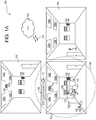
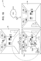
- Example control-source devices may include a remote control devices 116, 142, and 154, an occupancy sensor 112, a daylight sensor 150, a window sensor 180, and/or a network device 128.
- the control-source devices may include a wired or wireless device.
- the control-source devices may include a control device, such as a dimmer switch, an electronic switch, or the like.
- the load control system 100 may be commissioned to enable control of electrical loads based on commands communicated between control devices (e . g ., control-source devices and control-target devices) configured to control the electrical loads.
- control devices e . g ., control-source devices and control-target devices
- control devices may be associated with one another and association information may be stored thereon, or at other devices, which may be used to communicate and identify digital commands at associated devices for controlling electrical devices in the system.
- the association information may include the unique identifier of one or more of the associated devices.
- the association information may be stored at the control devices, or at other devices that may be implemented to enable communication and/or identification of digital commands between the control devices.
- the occupancy sensor 112 may be configured to detect occupancy and/or vacancy conditions in the load control environment 100 in which the load control system is installed.
- the occupancy sensor 112 may transmit digital messages to control-target devices via the RF communication signals 172 in response to detecting the occupancy or vacancy conditions.
- the occupancy sensor 112 may operate as a vacancy sensor, such that digital messages are transmitted in response to detecting a vacancy condition ( e . g ., digital messages may not be transmitted in response to detecting an occupancy condition).
- the occupancy sensor 112 may enter an association mode and may transmit association messages via the RF communication signals 172 in response to actuation of a button 114 on the occupancy sensor 112. Examples of RF load control systems having occupancy and/or vacancy sensors are described in greater detail in U.S. Patent No.
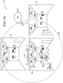
- the system controller 160 may also, or alternatively, communicate via RF communication signals 170 (e.g., NFC; BLUETOOTH®; WI-FI®; cellular; a proprietary communication channel, such as CLEAR CONNECTTM, etc. ).
- the system controller 160 may communicate over the Internet 164, or other network, using RF communication signals 170.
- the RF communication signals 170 may be transmitted using a different protocol and/or wireless band than the RF communication signals 172.
- the RF communication signals 170 may be transmitted using WI-FI® or cellular signals and the RF communication signals 172 may be transmitted using another RF communication protocol, such as BLUETOOTH®, ZIGBEE®, or a proprietary communication protocol.
- the RF communication signals 170 may be transmitted using the same protocol and/or wireless band as the RF communication signals 172.
- the RF communication signals 170 and the RF communication signals 172 may be transmitted using WI-FI® or a proprietary communication protocol.
- Example preset configurations may include bedtime preset for when a user is going to bed, a movie watching preset for when the user is watching television or a movie, an away preset for when a user is away from the building, a home preset for when the user is in the building, or other preset configurations a user may define for an occasion.
- the discovery criteria may include a load state of an electronic load controlled by a control device.
- the load state may be an on/off state of an electrical load controlled by a load control device.
- the load state may be the dimming level, or a dimming level range, of a lighting load.
- the control devices may identify a load state of an electrical load and identify when the load state has been met for discovery.
- the control devices may provide the load state to another device, such as the system controller 160 or the network device 128, which may identify when the load state for being discovered has been met.
- the load state being included in the discovery criteria may allow the user 132 to adjust the load state of electrical loads using devices the user 132 wishes to discover.
- the user 132 may select the identified device on the network device 128 for identifying the control device as the load control discovery device 190.
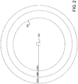
- the user 132 may identify different control devices as the load control discovery device 190 and discover different devices by moving the established discovery range 134 within a location or to different locations.
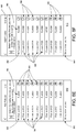
- the user may select the discovery range 606 for the load control discovery device 190, 202, 302.
- the discovery range 606 may be established using a dropdown box or other button (not shown) on the GUI 602.
- assigning the remote control device 116 as the load control discovery device 190, 202, 302 may designate that the discovery range 134 be centered on the remote control device 116.
- the load control discovery device assignment button 632 is selected that corresponds to the remote control device, the discovery range 134 may be sent to the system controller 160, 306 and/or the remote control discovery device 116 for calculating the transmission power or receive threshold for the discovery range of discovery messages transmitted from the load control discovery device 190, 202, 302.
- the GUI 602 may identify control-source devices and control-target devices and may allow association between control-source devices and control-target devices.
- the GUI 602 may disallow association between the same type of devices ( e . g ., control-source devices and control-source devices, control-target devices and control-target devices, etc.).
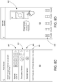
- FIG. 7 depicts an example graphical user interface (GUI) 700 that may be used to perform location association at a network device, such as the network device 128, 308 for example.
- the GUI 700 may be used to select a location 714 with which a discovered control device may be associated or disassociated.
- the GUI 700 may be displayed at the network device 128, 308 upon selecting location association button 636 (shown in FIG. 6 ).
- Different locations 714 may be displayed on the GUI 700 for being associated with control devices.
- the locations 714 may be displayed by name and/or by identifier.
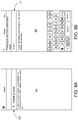
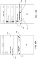
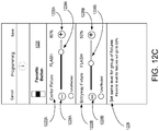
- the network device may receive and display a list (e.g., the list 842) of lighting control devices in lighting fixtures within a discovery range of the occupancy sensor.
- the network device may include an already-associated indication 850 below the fixture identifiers 844 of the load control devices of those lighting fixtures that were previously associated with an input device.
- the already-associated indication 850 may indicate that the load control devices in the lighting fixtures were previously associated with a remote control device.
- the already-associated indication 850 may identify to the user the fixture identifiers 844 of the load control devices in the lighting fixtures that may be associated with the occupancy sensor. For example, the user may wish to associate the occupancy sensor with the load control devices in the lighting fixtures that were previously associated with the remote control device.
- Such configuration may include, for each area in a building, associating one or more control-source devices in the area with one or more control-target devices in that area such that the control-source devices may control the control-target devices in that area.
- the configuration may further include configuring a system controller such that the system controller may control the devices ( e . g ., automatically through scheduled programs, through user input via a network device, etc .) in each area.
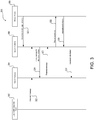
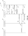
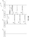
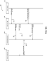
- the system controller 906 may communicate a single value (e.g ., -50dBm) and a control-target device 904 may communicate the acknowledgement message to the system controller 906 if its respective RSSI value is higher than the value.
- a single value e.g ., -50dBm
- a control-target device 904 may communicate the acknowledgement message to the system controller 906 if its respective RSSI value is higher than the value.
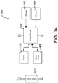
- FIG. 17 is a block diagram illustrating an example control-source device 1700 as described herein.
- the control-source device 1700 may be a remote control device, an occupancy sensor, a daylight sensor, a window sensor, a temperature sensor, and/or the like.
- the control-source device 1700 may include a control circuit 1702 for controlling the functionality of the control-source device 1700.
- the control circuit 1702 may include one or more general purpose processors, special purpose processors, conventional processors, digital signal processors (DSPs), microprocessors, integrated circuits, a programmable logic device (PLD), application specific integrated circuits (ASICs), or the like.
- the control circuit 1702 may perform signal coding, data processing, power control, input/output processing, or any other functionality that enables the control-source device 1700 to perform as described herein.
Landscapes
- Engineering & Computer Science (AREA)
- Automation & Control Theory (AREA)
- Computer Networks & Wireless Communication (AREA)
- General Engineering & Computer Science (AREA)
- Physics & Mathematics (AREA)
- General Physics & Mathematics (AREA)
- Signal Processing (AREA)
- Manufacturing & Machinery (AREA)
- Quality & Reliability (AREA)
- Selective Calling Equipment (AREA)
- Circuit Arrangement For Electric Light Sources In General (AREA)
- Power Engineering (AREA)
Claims (15)
- Anlagensteuerung (106) für eine Anlage, die eine Vielzahl von Steuervorrichtungen umfasst, wobei die Anlagensteuerung (106) Folgendes umfasst:wenigstens eine Kommunikationsschaltung (1506), wobei die wenigstens eine Kommunikationsschaltung (1506) zum Senden und Empfangen digitaler Nachrichten konfiguriert ist;eine Steuerschaltung (1402, 1502, 1604, 1702), die konfiguriert ist zum:Bestimmen einer Laststeuerungserkennungsvorrichtung, wobei die Laststeuerungserkennungsvorrichtung entweder eine Steuerquellenvorrichtung (902) oder eine Steuerzielvorrichtung (904) ist, die in der Vielzahl von Steuervorrichtungen beinhaltet ist, wobei die Steuerzielvorrichtung (904) in der Lage ist, eine Leistungsmenge zu steuern, die einer elektrischen Last an einer Position basierend auf digitalen Nachrichten, die von der Steuerquellenvorrichtung (902) empfangen werden, zugeführt wird;Erkennen von einer oder mehreren der Vielzahl von Steuervorrichtungen, die eine Erkennungsnachricht von der Laststeuerungserkennungsvorrichtung empfangen haben;Benachrichtigen einer Netzwerkvorrichtung (128, 308) der erkannten einen oder mehreren der Vielzahl von Steuervorrichtungen, die die Erkennungsnachricht empfangen haben;Empfangen, über die wenigstens eine Kommunikationsschaltung (1506), von Zuordnungsinformationen von der Netzwerkvorrichtung (128, 308), die eine Zuordnung von wenigstens einer der erkannten einen oder mehreren der Vielzahl von Steuervorrichtungen zu der Position der elektrischen Last anzeigen; undSpeichern der Zuordnungsinformationen zum Ermöglichen der Steuerung der elektrischen Last an der Position.
- Anlagensteuerung (106) nach Anspruch 1, wobei die Steuerschaltung (1402, 1502, 1604, 1702) konfiguriert ist zum:Empfangen, über die wenigstens eine Kommunikationsschaltung (1506), der Erkennungsnachricht von der Laststeuerungserkennungsvorrichtung, wobei die Laststeuerungserkennungsvorrichtung basierend auf der von der Laststeuerungserkennungsvorrichtung empfangenen Erkennungsnachricht bestimmt wird;Erkennen der einen oder der mehreren der Vielzahl von Steuervorrichtungen, die die Erkennungsnachricht empfangen haben, basierend auf einer Bestätigungsnachricht von jeder Steuervorrichtung der erkannten einen oder mehreren der Vielzahl von Steuervorrichtungen, wobei die Bestätigungsnachricht eine Vorrichtungskennung der Steuervorrichtung beinhaltet;Senden, über die Kommunikationsschaltung (1506), einer Anforderung zur Bestätigung des Empfangs der Erkennungsnachricht an die Vielzahl von Steuervorrichtungen; undEmpfangen der Bestätigungsnachricht als Reaktion auf die Anforderung zur Bestätigung des Empfangs der Erkennungsnachricht.
- Anlagensteuerung (106) nach Anspruch 2, wobei die Bestätigungsnachricht von jeder Steuervorrichtung der erkannten Steuervorrichtungen eine Signalstärke beinhaltet, bei der die Steuervorrichtung die Erkennungsnachricht empfangen hat; wobei die Steuerschaltung (1402, 1502, 1604, 1702) konfiguriert ist, um einen geordneten Datensatz für die erkannte eine oder die erkannten mehreren der Vielzahl von Steuervorrichtungen basierend auf der Signalstärke zu bestimmen, bei der jede Steuervorrichtung der erkannten einen oder mehreren der Vielzahl von Steuervorrichtungen die Erkennungsnachricht empfangen hat; und wobei der geordnete Datensatz eine vordefinierte Anzahl der erkannten einen oder mehreren der Vielzahl von Steuervorrichtungen mit einer höchsten Signalstärke oder mit der Signalstärke oberhalb einer vordefinierten Signalstärkeschwelle beinhaltet.
- Anlagensteuerung (106) nach Anspruch 1, wobei die Steuerschaltung (1402, 1502, 1604, 1702) konfiguriert ist, um eine Anzeige eines Erkennungsbereichs für die Übertragung der Erkennungsnachricht zu bestimmen und die Laststeuerungserkennungsvorrichtung über den Erkennungsbereich zu benachrichtigen.
- Anlagensteuerung (106) nach Anspruch 1, wobei die Zuordnungsinformationen wenigstens eine Vorrichtung anzeigen, der die erkannte eine oder die erkannten mehreren der Vielzahl von Steuervorrichtungen zugeordnet sind.
- Anlagensteuerung (106) nach Anspruch 1, wobei die Steuerschaltung (1402, 1502, 1604, 1702) ferner konfiguriert ist, um Steuerungskonfigurationsinformationen von der Netzwerkvorrichtung (128, 308) zu empfangen.
- Anlagensteuerung (106) nach Anspruch 1, wobei die wenigstens eine Kommunikationsschaltung (1506) eine erste Kommunikationsschaltung (1506) umfasst, die konfiguriert ist, um mit der Vielzahl von Steuervorrichtungen über einen ersten Kommunikationskanal zu kommunizieren, und eine zweite Kommunikationsschaltung (1506) umfasst, die konfiguriert ist, um mit der Netzwerkvorrichtung (128, 308) über einen zweiten Kommunikationskanal zu kommunizieren.
- Anlagensteuerung (106) nach Anspruch 1, wobei die Steuerschaltung (1402, 1502, 1604, 1702) konfiguriert ist zum:Senden, über die Kommunikationsschaltung (1506), einer Erkennungsauslösernachricht an die Laststeuerungserkennungsvorrichtung; undEmpfangen der Erkennungsnachricht als Reaktion auf die Erkennungsauslösernachricht.
- Verfahren zum Verwenden bei der Inbetriebnahme einer Laststeuerungsanlage, wobei das Verfahren Folgendes umfasst:Bestimmen einer Laststeuerungserkennungsvorrichtung, wobei die Laststeuerungserkennungsvorrichtung entweder eine Steuerquellenvorrichtung (902) oder eine Steuerzielvorrichtung (904) ist, die in einer Vielzahl von Steuervorrichtungen beinhaltet ist, wobei die Steuerzielvorrichtung (904) in der Lage ist, eine Leistungsmenge zu steuern, die einer elektrischen Last an einer Position basierend auf digitalen Nachrichten, die von der Steuerquellenvorrichtung (902) empfangen werden, zugeführt wird;Erkennen einer oder mehrerer der Vielzahl von Steuervorrichtungen, die eine Erkennungsnachricht von der Laststeuerungserkennungsvorrichtung empfangen haben;Benachrichtigen einer Netzwerkvorrichtung (128, 308) der erkannten einen oder mehreren der Vielzahl von Steuervorrichtungen, die die Erkennungsnachricht empfangen haben;Empfangen von Zuordnungsinformationen von der Netzwerkvorrichtung (128, 308), die eine Zuordnung von wenigstens einer der erkannten einen oder mehreren der Vielzahl von Steuervorrichtungen zu der Position der elektrischen Last anzeigen; undSpeichern der Zuordnungsinformationen zum Ermöglichen der Steuerung der elektrischen Last an der Position.
- Verfahren nach Anspruch 9, ferner Folgendes umfassend:Empfangen der Erkennungsnachricht von der Laststeuerungserkennungsvorrichtung, wobei die Laststeuerungserkennungsvorrichtung basierend auf der von der Laststeuerungserkennungsvorrichtung empfangenen Erkennungsnachricht bestimmt wird;Erkennen der einen oder mehreren der Vielzahl von Steuervorrichtungen, die die Erkennungsnachricht empfangen haben, basierend auf einer Bestätigungsnachricht von jeder Steuervorrichtung der erkannten einen oder mehreren der Vielzahl von Steuervorrichtungen, wobei die Bestätigungsnachricht eine Vorrichtungskennung der Steuervorrichtung beinhaltet;Senden einer Anforderung zum Bestätigen des Empfangs der Erkennungsnachricht an die Vielzahl von Steuervorrichtungen; undEmpfangen der Bestätigungsnachricht als Reaktion auf die Anforderung zum Bestätigen des Empfangs der Erkennungsnachricht.
- Verfahren nach Anspruch 10, wobei die Bestätigungsnachricht von jeder Steuervorrichtung der erkannten Steuervorrichtungen eine Signalstärke beinhaltet, bei der die Steuervorrichtung die Erkennungsnachricht empfangen hat; wobei das Verfahren ferner das Bestimmen eines geordneten Datensatzes für die erkannte eine oder erkannten mehreren der Vielzahl von Steuervorrichtungen basierend auf der Signalstärke, bei der jede Steuervorrichtung der erkannten einen oder mehreren der Vielzahl von Steuervorrichtungen die Erkennungsnachricht empfangen hat, umfasst; und wobei der geordnete Datensatz eine vordefinierte Anzahl der erkannten einen oder mehreren der Vielzahl von Steuervorrichtungen mit einer höchsten Signalstärke oder mit der Signalstärke oberhalb einer vordefinierten Signalstärkeschwelle beinhaltet.
- Verfahren nach Anspruch 9, ferner Folgendes umfassend:Bestimmen einer Anzeige eines Erkennungsbereichs für die Übertragung der Erkennungsmeldung undBenachrichtigen der Laststeuerungserkennungsvorrichtung über den Erkennungsbereich.
- Verfahren nach Anspruch 9, wobei die Zuordnungsinformationen wenigstens eine Vorrichtung anzeigen, der die erkannte eine oder die erkannten mehreren der Vielzahl von Steuervorrichtungen zugeordnet sind.
- Verfahren nach Anspruch 9, ferner umfassend das Empfangen von Steuerungskonfigurationsinformationen von der Netzwerkvorrichtung (128, 308).
- Verfahren nach Anspruch 9, ferner Folgendes umfassend:Senden einer Erkennungsauslösernachricht an die Laststeuerungserkennungsvorrichtung; undEmpfangen der Erkennungsnachricht als Reaktion auf die Erkennungsauslösernachricht.
Priority Applications (1)
| Application Number | Priority Date | Filing Date | Title |
|---|---|---|---|
| EP20182486.9A EP3740044B1 (de) | 2015-10-30 | 2016-10-28 | Inbetriebnahme von laststeuerungsanlagen |
Applications Claiming Priority (4)
| Application Number | Priority Date | Filing Date | Title |
|---|---|---|---|
| US201562249117P | 2015-10-30 | 2015-10-30 | |
| US201662279409P | 2016-01-15 | 2016-01-15 | |
| US201662326466P | 2016-04-22 | 2016-04-22 | |
| PCT/US2016/059590 WO2017075542A2 (en) | 2015-10-30 | 2016-10-28 | Commissioning load control systems |
Related Child Applications (1)
| Application Number | Title | Priority Date | Filing Date |
|---|---|---|---|
| EP20182486.9A Division EP3740044B1 (de) | 2015-10-30 | 2016-10-28 | Inbetriebnahme von laststeuerungsanlagen |
Publications (2)
| Publication Number | Publication Date |
|---|---|
| EP3369291A2 EP3369291A2 (de) | 2018-09-05 |
| EP3369291B1 true EP3369291B1 (de) | 2020-07-22 |
Family
ID=57321429
Family Applications (2)
| Application Number | Title | Priority Date | Filing Date |
|---|---|---|---|
| EP20182486.9A Active EP3740044B1 (de) | 2015-10-30 | 2016-10-28 | Inbetriebnahme von laststeuerungsanlagen |
| EP16795493.2A Active EP3369291B1 (de) | 2015-10-30 | 2016-10-28 | Inbetriebnahme von laststeuerungsanlagen |
Family Applications Before (1)
| Application Number | Title | Priority Date | Filing Date |
|---|---|---|---|
| EP20182486.9A Active EP3740044B1 (de) | 2015-10-30 | 2016-10-28 | Inbetriebnahme von laststeuerungsanlagen |
Country Status (6)
| Country | Link |
|---|---|
| US (6) | US10379505B2 (de) |
| EP (2) | EP3740044B1 (de) |
| CN (2) | CN112764402B (de) |
| CA (3) | CA3003146C (de) |
| MX (2) | MX394420B (de) |
| WO (1) | WO2017075542A2 (de) |
Families Citing this family (72)
| Publication number | Priority date | Publication date | Assignee | Title |
|---|---|---|---|---|
| US9495708B2 (en) | 2012-06-11 | 2016-11-15 | Acorns Grow Incorporated | Systems and methods for managing electronic interactive gaming-based investments |
| US9174085B2 (en) | 2012-07-31 | 2015-11-03 | John Paul Foley | Exercise system and method |
| US11610664B2 (en) | 2012-07-31 | 2023-03-21 | Peloton Interactive, Inc. | Exercise system and method |
| US10339795B2 (en) * | 2013-12-24 | 2019-07-02 | Lutron Technology Company Llc | Wireless communication diagnostics |
| USD780785S1 (en) | 2015-03-27 | 2017-03-07 | Twitter, Inc. | Display screen with graphical user interface for live video sharing |
| US20160348879A1 (en) | 2015-05-29 | 2016-12-01 | Black & Decker Inc. | Work Light |
| WO2017025854A1 (en) * | 2015-08-07 | 2017-02-16 | Tridonic Gmbh & Co Kg | Commissioning device for commissioning installed building technology devices |
| WO2017075542A2 (en) * | 2015-10-30 | 2017-05-04 | Lutron Electronics Co., Inc | Commissioning load control systems |
| DE102016203530A1 (de) * | 2016-03-03 | 2017-09-07 | Osram Gmbh | Leuchte mit eingebauten Netzwerkzugangspunkt und Beleuchtungsanlage mit einem drahtlosen Netzwerk |
| USD822692S1 (en) * | 2016-06-14 | 2018-07-10 | Itt Manufacturing Enterprises Llc. | Display screen or portion thereof with graphical user interface |
| US10205606B2 (en) * | 2016-06-15 | 2019-02-12 | Abl Ip Holding Llc | Mesh over-the-air (OTA) luminaire firmware update |
| CA3114088C (en) | 2016-07-22 | 2024-01-09 | Lutron Technology Company Llc | Modular lighting panel |
| USD849765S1 (en) * | 2016-07-29 | 2019-05-28 | Samsung Electronics Co., Ltd. | Display screen or portion thereof with graphical user interface |
| USD832870S1 (en) * | 2016-08-16 | 2018-11-06 | Beijing Kingsoft Internet Security Software Co., Ltd. | Mobile communication terminal display screen with graphical user interface |
| CN109565456B (zh) * | 2016-08-19 | 2022-02-08 | Pcms控股公司 | 在智能家居环境中利用设备独立场景的系统和方法 |
| US10506688B2 (en) | 2016-08-24 | 2019-12-10 | Lutron Technology Company Llc | Method of identifying a lighting fixture |
| WO2018044721A1 (en) * | 2016-08-27 | 2018-03-08 | Peloton Interactive, Inc. | Exercise system and method |
| USD802622S1 (en) * | 2016-08-29 | 2017-11-14 | Lutron Electronics Co., Inc. | Display screen or portion thereof with graphical user interface |
| US10348514B2 (en) | 2016-10-26 | 2019-07-09 | Abl Ip Holding Llc | Mesh over-the-air (OTA) driver update using site profile based multiple platform image |
| CA3155434C (en) | 2017-02-07 | 2024-07-02 | Lutron Technology Company Llc | Audio-based load control system |
| CN115755687B (zh) * | 2017-02-20 | 2025-07-01 | 路创技术有限责任公司 | 集成和控制多个负载控制系统 |
| US10715354B2 (en) | 2017-02-20 | 2020-07-14 | Lutron Technology Company Llc | Integrating and controlling multiple load control systems |
| USD837240S1 (en) * | 2017-03-02 | 2019-01-01 | The Procter & Gamble Company | Display screen with graphical user interface |
| US20180313558A1 (en) * | 2017-04-27 | 2018-11-01 | Cisco Technology, Inc. | Smart ceiling and floor tiles |
| CN115379617A (zh) * | 2017-06-15 | 2022-11-22 | 路创技术有限责任公司 | 与负载控制系统通信以及控制负载控制系统 |
| GB2564396B (en) * | 2017-07-06 | 2020-12-02 | Advanced Risc Mach Ltd | Light animation service |
| JP6945159B2 (ja) * | 2017-08-09 | 2021-10-06 | パナソニックIpマネジメント株式会社 | 照明システム、無線コントローラ、制御方法及びプログラム |
| USD890792S1 (en) * | 2017-08-10 | 2020-07-21 | Jpmorgan Chase Bank, N.A. | Display screen or portion thereof with a graphical user interface |
| USD903700S1 (en) * | 2017-08-10 | 2020-12-01 | Jpmorgan Chase Bank, N.A. | Display screen or portion thereof with a graphical user interface |
| US11430022B1 (en) * | 2017-08-16 | 2022-08-30 | Energy Hub, Inc. | Enrollment verification in energy management |
| USD887437S1 (en) | 2017-11-09 | 2020-06-16 | Siemens Schweiz Ag | Display screen or portion thereof with graphical user interface |
| USD934266S1 (en) | 2017-11-12 | 2021-10-26 | Peloton Interactive, Inc. | Display screen having a graphical user interface or portion thereof |
| USD859460S1 (en) | 2017-12-01 | 2019-09-10 | Delos Living Llc | Display screen or portion thereof with graphical user interface |
| USD862494S1 (en) | 2017-12-01 | 2019-10-08 | Delos Living Llc | Display screen or portion thereof with graphical user interface |
| WO2019157390A1 (en) | 2018-02-09 | 2019-08-15 | Lutron Technology Company Llc | Self-test procedure for a control device |
| CN110959260B (zh) * | 2018-03-09 | 2023-02-17 | 松下电器(美国)知识产权公司 | 设备以及方法 |
| EP3541150B1 (de) * | 2018-03-16 | 2020-11-25 | Helvar Oy Ab | Leuchtendetektion |
| US11522732B2 (en) | 2018-08-02 | 2022-12-06 | Lutron Technology Company Llc | Camera-based commissioning |
| USD915418S1 (en) * | 2018-08-22 | 2021-04-06 | Honeywell International Inc. | Display screen or portion thereof with graphical user interface |
| USD902952S1 (en) | 2018-09-04 | 2020-11-24 | Lutron Technology Company Llc | Display screen or portion thereof with set of animated graphical user interfaces |
| USD876449S1 (en) * | 2018-09-12 | 2020-02-25 | Apple Inc. | Electronic device or portion thereof with animated graphical user interface |
| USD917501S1 (en) * | 2018-10-05 | 2021-04-27 | Pear Therapeutics, Inc. | Display screen or portion thereof with an animated graphical user interface |
| USD918959S1 (en) * | 2018-11-06 | 2021-05-11 | Samsung Electronics Co., Ltd. | Display screen or portion thereof with graphical user interface |
| USD932513S1 (en) | 2018-11-07 | 2021-10-05 | Promontory MortgagePath LLC | Computer display panel with graphic user interface comprising a group of interest rate icons for a mortgage application |
| USD902230S1 (en) | 2018-11-07 | 2020-11-17 | Promontory MortgagePath LLC | Computer display panel with a transitional graphical user interface |
| USD902957S1 (en) | 2018-11-07 | 2020-11-24 | Promontory MortgagePath LLC | Computer display panel with a transitional graphical user interface |
| USD906361S1 (en) * | 2018-11-07 | 2020-12-29 | Promontory Fulfillment Services Llc | Computer display panel with a graphical user interface for a mortgage application |
| USD902231S1 (en) | 2018-11-07 | 2020-11-17 | Promontory MortgagePath LLC | Computer display panel with a transitional graphical user interface |
| USD955423S1 (en) | 2018-11-07 | 2022-06-21 | Promontory MortgagePath LLC | Computer display panel with graphical user interface for a mortgage application providing a factory list view |
| WO2020181011A1 (en) | 2019-03-04 | 2020-09-10 | Lutron Technology Company Llc | Direct-current power distribution in a control system |
| CA3132922A1 (en) * | 2019-03-08 | 2020-10-29 | Lutron Technology Company Llc | Commissioning and controlling load control devices |
| US11683235B2 (en) | 2019-06-21 | 2023-06-20 | Lutron Technology Company Llc | Network formation for a load control system |
| USD909402S1 (en) | 2019-09-03 | 2021-02-02 | Lutron Technology Company Llc | Display screen or portion thereof with animated graphical user interface |
| US10932349B1 (en) * | 2019-09-16 | 2021-02-23 | Abl Ip Holding Llc | Lighting control system commissioning using lighting control system sensors |
| USD916840S1 (en) * | 2019-09-23 | 2021-04-20 | eCU Technology, LLC | Display screen or portion thereof with a graphical user interface |
| USD956086S1 (en) * | 2019-09-23 | 2022-06-28 | Beijing Xiaomi Mobile Software Co., Ltd. | Mobile phone with animated graphical user interface |
| US11770324B1 (en) | 2019-12-02 | 2023-09-26 | Lutron Technology Company Llc | Processing advertisement messages in a mesh network |
| EP4070484B1 (de) | 2019-12-02 | 2025-10-15 | Lutron Technology Company LLC | Perzentil-bodenverbindungsqualifikation |
| WO2021127458A1 (en) | 2019-12-20 | 2021-06-24 | Lutron Technology Company Llc | Handling loss or removal of devices in a mesh network |
| USD949163S1 (en) | 2019-12-30 | 2022-04-19 | Twitter, Inc. | Display screen with graphical user interface for video conferencing |
| US11469916B2 (en) * | 2020-01-05 | 2022-10-11 | Brilliant Home Technology, Inc. | Bridging mesh device controller for implementing a scene |
| CN115104298B (zh) | 2020-02-11 | 2025-09-12 | 昕诺飞控股有限公司 | 用于在网络中选择性地调试节点设备的方法和协调器设备 |
| CN112703823B (zh) * | 2020-03-26 | 2023-10-10 | 松下知识产权经营株式会社 | 照明装置的快速调试 |
| CN115735414A (zh) * | 2020-05-01 | 2023-03-03 | 路创技术有限责任公司 | 自动调整用于发现无线控制装置的发现范围 |
| WO2021226526A1 (en) * | 2020-05-08 | 2021-11-11 | Lutron Technology Company, LLC | Assigning router devices in a mesh network |
| USD959462S1 (en) * | 2020-07-15 | 2022-08-02 | Vyaire Medical, Inc. | Computing device with graphical user interface for communicating health-related messages regarding ventilated patients |
| MX2022016416A (es) | 2020-09-16 | 2023-03-06 | Lutron Tech Co Llc | Distribución de energía de corriente continua en un sistema de control. |
| US11743996B1 (en) | 2020-09-18 | 2023-08-29 | Lutron Technology Company Llc | Load control system comprising linear lighting fixtures |
| CN115868173A (zh) | 2020-09-22 | 2023-03-28 | 路创技术有限责任公司 | 聚合传感器数据的发射 |
| US20230138490A1 (en) * | 2021-10-29 | 2023-05-04 | Beth Ann Wexell | Roof Sunshade Device |
| CN115248561A (zh) * | 2022-08-26 | 2022-10-28 | 珠海格力电器股份有限公司 | 一种设备跨区域联动切换方法及系统 |
| USD1059391S1 (en) * | 2022-12-19 | 2025-01-28 | Meta Platforms, Inc. | Display screen or portion thereof with a graphical user interface |
Citations (3)
| Publication number | Priority date | Publication date | Assignee | Title |
|---|---|---|---|---|
| US20120082062A1 (en) * | 2009-06-10 | 2012-04-05 | Koninklijke Philips Electronics N.V. | Advanced commissioning of wireless network systems |
| US20140265568A1 (en) * | 2013-03-14 | 2014-09-18 | Lutron Electronics Co., Inc. | Comissioning load control systems |
| US20150223152A1 (en) * | 2012-08-22 | 2015-08-06 | Koninklijke Philips N.V. | Network discovery with touchlink option |
Family Cites Families (39)
| Publication number | Priority date | Publication date | Assignee | Title |
|---|---|---|---|---|
| US5248919A (en) | 1992-03-31 | 1993-09-28 | Lutron Electronics Co., Inc. | Lighting control device |
| US6791467B1 (en) * | 2000-03-23 | 2004-09-14 | Flextronics Semiconductor, Inc. | Adaptive remote controller |
| WO2003055512A1 (en) | 2001-12-21 | 2003-07-10 | Novo Nordisk Health Care Ag | Liquid composition of factor vii polypeptides |
| US20040255029A1 (en) * | 2003-06-16 | 2004-12-16 | Microsoft Corporation | Discovery and control protocol for intelligent displays |
| US7363028B2 (en) * | 2003-11-04 | 2008-04-22 | Universal Electronics, Inc. | System and method for controlling device location determination |
| US7155305B2 (en) * | 2003-11-04 | 2006-12-26 | Universal Electronics Inc. | System and methods for home appliance identification and control in a networked environment |
| US7656308B2 (en) * | 2004-10-28 | 2010-02-02 | Heathco Llc | AC powered wireless control 3-way light switch transmitter |
| US8994276B2 (en) * | 2006-03-28 | 2015-03-31 | Wireless Environment, Llc | Grid shifting system for a lighting circuit |
| ES2629609T3 (es) * | 2006-06-29 | 2017-08-11 | Philips Lighting Holding B.V. | Implementación y puesta en marcha de red limitada autónoma |
| JP5027642B2 (ja) * | 2007-12-25 | 2012-09-19 | パナソニック株式会社 | 照明制御システム |
| EP2319255B1 (de) * | 2008-08-27 | 2015-12-23 | Koninklijke Philips N.V. | Inbetriebnahme eines netzwerksystems |
| US8228184B2 (en) | 2008-09-03 | 2012-07-24 | Lutron Electronics Co., Inc. | Battery-powered occupancy sensor |
| US8009042B2 (en) | 2008-09-03 | 2011-08-30 | Lutron Electronics Co., Inc. | Radio-frequency lighting control system with occupancy sensing |
| US9363855B2 (en) * | 2009-01-06 | 2016-06-07 | Koninklijke Philips N.V. | Control system for controlling one or more controllable devices sources and method for enabling such control |
| US8199010B2 (en) | 2009-02-13 | 2012-06-12 | Lutron Electronics Co., Inc. | Method and apparatus for configuring a wireless sensor |
| US8451116B2 (en) | 2009-03-27 | 2013-05-28 | Lutron Electronics Co., Inc. | Wireless battery-powered daylight sensor |
| US8410706B2 (en) | 2009-03-27 | 2013-04-02 | Lutron Electronics Co., Inc. | Method of calibrating a daylight sensor |
| US8400258B2 (en) * | 2009-04-30 | 2013-03-19 | Echoflex Solutions, Inc. | Method of remotely configuring a controller responsive to wireless signals |
| US8581707B2 (en) * | 2009-12-16 | 2013-11-12 | Pyramid Meriden Inc. | Methods and apparatus for identifying and categorizing distributed devices |
| US8471779B2 (en) | 2010-05-17 | 2013-06-25 | Lutron Electronics Co., Inc. | Wireless battery-powered remote control with label serving as antenna element |
| KR20120087635A (ko) * | 2011-01-28 | 2012-08-07 | 삼성전자주식회사 | 무선 pan 프록시 장치를 이용하여 원격으로 가전 기기를 제어하는 방법 및 장치 |
| US20120306621A1 (en) * | 2011-06-03 | 2012-12-06 | Leviton Manufacturing Co., Inc. | Lighting control network configuration with rfid devices |
| US10271407B2 (en) * | 2011-06-30 | 2019-04-23 | Lutron Electronics Co., Inc. | Load control device having Internet connectivity |
| US9553451B2 (en) * | 2011-12-28 | 2017-01-24 | Lutron Electronics Co., Inc. | Load control system having independently-controlled units responsive to a broadcast controller |
| CN102542768B (zh) * | 2012-02-10 | 2013-10-09 | 华为终端有限公司 | 一种射频设备的配对方法、设备及系统 |
| US9489005B2 (en) * | 2012-03-28 | 2016-11-08 | Lutron Electronics Co., Inc. | Method and apparatus for phase-controlling a load |
| US9679696B2 (en) | 2012-11-14 | 2017-06-13 | Lutron Electronics Co., Inc. | Wireless load control device |
| US9413171B2 (en) * | 2012-12-21 | 2016-08-09 | Lutron Electronics Co., Inc. | Network access coordination of load control devices |
| US9585226B2 (en) * | 2013-03-12 | 2017-02-28 | Lutron Electronics Co., Inc. | Identification of load control devices |
| EP2974553B1 (de) * | 2013-03-15 | 2019-08-14 | Cooper Technologies Company | Systeme und verfahren zur selbstinbetriebnahme und ortung eines beleuchtungssystems |
| US11426325B2 (en) * | 2013-03-15 | 2022-08-30 | Hayward Industries, Inc. | System and method for dynamic device discovery and address assignment |
| CN104105155B (zh) * | 2013-04-01 | 2019-07-16 | 中兴通讯股份有限公司 | 接收设备发现信息、发送设备发现信息的方法和用户设备 |
| EP3039824A1 (de) * | 2013-08-30 | 2016-07-06 | Convida Wireless, LLC | Intelligente objektidentifikation in einem digitalen haushalt |
| US10149369B2 (en) * | 2013-11-21 | 2018-12-04 | Lutron Electronics Co., Inc. | Method of associating wireless control devices |
| US20150178421A1 (en) * | 2013-12-20 | 2015-06-25 | BrightBox Technologies, Inc. | Systems for and methods of modeling, step-testing, and adaptively controlling in-situ building components |
| DE102014202445A1 (de) * | 2014-02-11 | 2015-08-13 | Zumtobel Lighting Gmbh | Beleuchtungssystem und Verfahren zum Betrieb eines Beleuchtungssystems mit integriertem Sicherheitskonzept |
| EP3130203B1 (de) * | 2014-04-05 | 2021-09-08 | Enlighted Inc. | Konfigurierung einer vielzahl von sensorvorrichtungen einer struktur |
| US9741244B2 (en) * | 2014-05-30 | 2017-08-22 | Qualcomm Incorporated | Methods, smart objects, and systems for naming and interacting with smart objects |
| WO2017075542A2 (en) * | 2015-10-30 | 2017-05-04 | Lutron Electronics Co., Inc | Commissioning load control systems |
-
2016
- 2016-10-28 WO PCT/US2016/059590 patent/WO2017075542A2/en not_active Ceased
- 2016-10-28 EP EP20182486.9A patent/EP3740044B1/de active Active
- 2016-10-28 CA CA3003146A patent/CA3003146C/en active Active
- 2016-10-28 CA CA3220198A patent/CA3220198A1/en active Pending
- 2016-10-28 CN CN202110029524.3A patent/CN112764402B/zh active Active
- 2016-10-28 US US15/338,029 patent/US10379505B2/en active Active
- 2016-10-28 EP EP16795493.2A patent/EP3369291B1/de active Active
- 2016-10-28 CA CA3083189A patent/CA3083189C/en active Active
- 2016-10-28 CN CN201680070358.9A patent/CN108476575B/zh active Active
- 2016-10-28 MX MX2018005079A patent/MX394420B/es unknown
-
2018
- 2018-04-25 MX MX2022009481A patent/MX2022009481A/es unknown
-
2019
- 2019-06-28 US US16/457,126 patent/US10705495B2/en active Active
-
2020
- 2020-06-16 US US16/902,945 patent/US11303471B2/en active Active
-
2022
- 2022-04-11 US US17/717,221 patent/US11700147B2/en active Active
-
2023
- 2023-05-30 US US18/325,227 patent/US12301378B2/en active Active
-
2025
- 2025-05-09 US US19/203,975 patent/US20250337610A1/en active Pending
Patent Citations (3)
| Publication number | Priority date | Publication date | Assignee | Title |
|---|---|---|---|---|
| US20120082062A1 (en) * | 2009-06-10 | 2012-04-05 | Koninklijke Philips Electronics N.V. | Advanced commissioning of wireless network systems |
| US20150223152A1 (en) * | 2012-08-22 | 2015-08-06 | Koninklijke Philips N.V. | Network discovery with touchlink option |
| US20140265568A1 (en) * | 2013-03-14 | 2014-09-18 | Lutron Electronics Co., Inc. | Comissioning load control systems |
Also Published As
| Publication number | Publication date |
|---|---|
| US20250337610A1 (en) | 2025-10-30 |
| US10705495B2 (en) | 2020-07-07 |
| US20230308311A1 (en) | 2023-09-28 |
| US11303471B2 (en) | 2022-04-12 |
| CN112764402B (zh) | 2025-06-03 |
| US11700147B2 (en) | 2023-07-11 |
| CA3003146C (en) | 2020-08-25 |
| CA3083189A1 (en) | 2017-05-04 |
| CN112764402A (zh) | 2021-05-07 |
| CA3003146A1 (en) | 2017-05-04 |
| EP3369291A2 (de) | 2018-09-05 |
| CA3083189C (en) | 2024-01-02 |
| MX2018005079A (es) | 2018-08-23 |
| MX2022009481A (es) | 2022-08-25 |
| US20170123390A1 (en) | 2017-05-04 |
| US20190324412A1 (en) | 2019-10-24 |
| CA3220198A1 (en) | 2017-05-04 |
| US20200310371A1 (en) | 2020-10-01 |
| US12301378B2 (en) | 2025-05-13 |
| EP3740044B1 (de) | 2023-05-31 |
| CN108476575B (zh) | 2021-02-02 |
| EP3740044A1 (de) | 2020-11-18 |
| WO2017075542A2 (en) | 2017-05-04 |
| US20220239529A1 (en) | 2022-07-28 |
| CN108476575A (zh) | 2018-08-31 |
| US10379505B2 (en) | 2019-08-13 |
| MX394420B (es) | 2025-03-11 |
Similar Documents
| Publication | Publication Date | Title |
|---|---|---|
| US12301378B2 (en) | Commissioning load control systems | |
| US12153790B2 (en) | Communicating with and controlling load control systems | |
| US20240288842A1 (en) | Method of Identifying a Lighting Fixture | |
| CA3092068C (en) | Backing up a load control system | |
| HK40048306A (zh) | 调试负载控制系统 | |
| HK1259546A1 (zh) | 调试负载控制系统 | |
| HK1259546B (zh) | 调试负载控制系统 |
Legal Events
| Date | Code | Title | Description |
|---|---|---|---|
| STAA | Information on the status of an ep patent application or granted ep patent |
Free format text: STATUS: UNKNOWN |
|
| STAA | Information on the status of an ep patent application or granted ep patent |
Free format text: STATUS: THE INTERNATIONAL PUBLICATION HAS BEEN MADE |
|
| PUAI | Public reference made under article 153(3) epc to a published international application that has entered the european phase |
Free format text: ORIGINAL CODE: 0009012 |
|
| STAA | Information on the status of an ep patent application or granted ep patent |
Free format text: STATUS: REQUEST FOR EXAMINATION WAS MADE |
|
| 17P | Request for examination filed |
Effective date: 20180529 |
|
| AK | Designated contracting states |
Kind code of ref document: A2 Designated state(s): AL AT BE BG CH CY CZ DE DK EE ES FI FR GB GR HR HU IE IS IT LI LT LU LV MC MK MT NL NO PL PT RO RS SE SI SK SM TR |
|
| AX | Request for extension of the european patent |
Extension state: BA ME |
|
| RIN1 | Information on inventor provided before grant (corrected) |
Inventor name: FRICKE, WILLIAM BRYCE Inventor name: CLYMER, ERICA L. Inventor name: COURTNEY, BRIAN MICHAEL Inventor name: LUDWIG, JR., STEPHEN M. Inventor name: CRAFTS, JORDAN H. Inventor name: RAGHURAM, SANDEEP MUDABAIL Inventor name: WALSH, III, RICHARD, M. Inventor name: BARCO, KYLE THOMAS Inventor name: LENZ, JONATHAN T. Inventor name: KUMAR, SANJEEV Inventor name: KNODE, GALEN EDGAR Inventor name: BARNES, BRYAN ROBERT |
|
| DAV | Request for validation of the european patent (deleted) | ||
| DAX | Request for extension of the european patent (deleted) | ||
| STAA | Information on the status of an ep patent application or granted ep patent |
Free format text: STATUS: EXAMINATION IS IN PROGRESS |
|
| 17Q | First examination report despatched |
Effective date: 20190821 |
|
| GRAP | Despatch of communication of intention to grant a patent |
Free format text: ORIGINAL CODE: EPIDOSNIGR1 |
|
| STAA | Information on the status of an ep patent application or granted ep patent |
Free format text: STATUS: GRANT OF PATENT IS INTENDED |
|
| INTG | Intention to grant announced |
Effective date: 20191204 |
|
| RAP1 | Party data changed (applicant data changed or rights of an application transferred) |
Owner name: LUTRON TECHNOLOGY COMPANY LLC |
|
| GRAJ | Information related to disapproval of communication of intention to grant by the applicant or resumption of examination proceedings by the epo deleted |
Free format text: ORIGINAL CODE: EPIDOSDIGR1 |
|
| STAA | Information on the status of an ep patent application or granted ep patent |
Free format text: STATUS: EXAMINATION IS IN PROGRESS |
|
| REG | Reference to a national code |
Ref country code: DE Ref legal event code: R079 Ref document number: 602016040504 Country of ref document: DE Free format text: PREVIOUS MAIN CLASS: H05B0037020000 Ipc: H05B0047190000 |
|
| INTC | Intention to grant announced (deleted) | ||
| GRAP | Despatch of communication of intention to grant a patent |
Free format text: ORIGINAL CODE: EPIDOSNIGR1 |
|
| STAA | Information on the status of an ep patent application or granted ep patent |
Free format text: STATUS: GRANT OF PATENT IS INTENDED |
|
| RIC1 | Information provided on ipc code assigned before grant |
Ipc: H05B 47/19 20200101AFI20200430BHEP |
|
| GRAS | Grant fee paid |
Free format text: ORIGINAL CODE: EPIDOSNIGR3 |
|
| INTG | Intention to grant announced |
Effective date: 20200519 |
|
| GRAA | (expected) grant |
Free format text: ORIGINAL CODE: 0009210 |
|
| STAA | Information on the status of an ep patent application or granted ep patent |
Free format text: STATUS: THE PATENT HAS BEEN GRANTED |
|
| AK | Designated contracting states |
Kind code of ref document: B1 Designated state(s): AL AT BE BG CH CY CZ DE DK EE ES FI FR GB GR HR HU IE IS IT LI LT LU LV MC MK MT NL NO PL PT RO RS SE SI SK SM TR |
|
| REG | Reference to a national code |
Ref country code: GB Ref legal event code: FG4D |
|
| REG | Reference to a national code |
Ref country code: CH Ref legal event code: EP |
|
| REG | Reference to a national code |
Ref country code: DE Ref legal event code: R096 Ref document number: 602016040504 Country of ref document: DE |
|
| REG | Reference to a national code |
Ref country code: AT Ref legal event code: REF Ref document number: 1294687 Country of ref document: AT Kind code of ref document: T Effective date: 20200815 |
|
| REG | Reference to a national code |
Ref country code: IE Ref legal event code: FG4D |
|
| REG | Reference to a national code |
Ref country code: NL Ref legal event code: FP |
|
| REG | Reference to a national code |
Ref country code: LT Ref legal event code: MG4D |
|
| REG | Reference to a national code |
Ref country code: AT Ref legal event code: MK05 Ref document number: 1294687 Country of ref document: AT Kind code of ref document: T Effective date: 20200722 |
|
| PG25 | Lapsed in a contracting state [announced via postgrant information from national office to epo] |
Ref country code: NO Free format text: LAPSE BECAUSE OF FAILURE TO SUBMIT A TRANSLATION OF THE DESCRIPTION OR TO PAY THE FEE WITHIN THE PRESCRIBED TIME-LIMIT Effective date: 20201022 Ref country code: BG Free format text: LAPSE BECAUSE OF FAILURE TO SUBMIT A TRANSLATION OF THE DESCRIPTION OR TO PAY THE FEE WITHIN THE PRESCRIBED TIME-LIMIT Effective date: 20201022 Ref country code: GR Free format text: LAPSE BECAUSE OF FAILURE TO SUBMIT A TRANSLATION OF THE DESCRIPTION OR TO PAY THE FEE WITHIN THE PRESCRIBED TIME-LIMIT Effective date: 20201023 Ref country code: ES Free format text: LAPSE BECAUSE OF FAILURE TO SUBMIT A TRANSLATION OF THE DESCRIPTION OR TO PAY THE FEE WITHIN THE PRESCRIBED TIME-LIMIT Effective date: 20200722 Ref country code: HR Free format text: LAPSE BECAUSE OF FAILURE TO SUBMIT A TRANSLATION OF THE DESCRIPTION OR TO PAY THE FEE WITHIN THE PRESCRIBED TIME-LIMIT Effective date: 20200722 Ref country code: SE Free format text: LAPSE BECAUSE OF FAILURE TO SUBMIT A TRANSLATION OF THE DESCRIPTION OR TO PAY THE FEE WITHIN THE PRESCRIBED TIME-LIMIT Effective date: 20200722 Ref country code: FI Free format text: LAPSE BECAUSE OF FAILURE TO SUBMIT A TRANSLATION OF THE DESCRIPTION OR TO PAY THE FEE WITHIN THE PRESCRIBED TIME-LIMIT Effective date: 20200722 Ref country code: LT Free format text: LAPSE BECAUSE OF FAILURE TO SUBMIT A TRANSLATION OF THE DESCRIPTION OR TO PAY THE FEE WITHIN THE PRESCRIBED TIME-LIMIT Effective date: 20200722 Ref country code: PT Free format text: LAPSE BECAUSE OF FAILURE TO SUBMIT A TRANSLATION OF THE DESCRIPTION OR TO PAY THE FEE WITHIN THE PRESCRIBED TIME-LIMIT Effective date: 20201123 Ref country code: AT Free format text: LAPSE BECAUSE OF FAILURE TO SUBMIT A TRANSLATION OF THE DESCRIPTION OR TO PAY THE FEE WITHIN THE PRESCRIBED TIME-LIMIT Effective date: 20200722 |
|
| PG25 | Lapsed in a contracting state [announced via postgrant information from national office to epo] |
Ref country code: PL Free format text: LAPSE BECAUSE OF FAILURE TO SUBMIT A TRANSLATION OF THE DESCRIPTION OR TO PAY THE FEE WITHIN THE PRESCRIBED TIME-LIMIT Effective date: 20200722 Ref country code: RS Free format text: LAPSE BECAUSE OF FAILURE TO SUBMIT A TRANSLATION OF THE DESCRIPTION OR TO PAY THE FEE WITHIN THE PRESCRIBED TIME-LIMIT Effective date: 20200722 Ref country code: LV Free format text: LAPSE BECAUSE OF FAILURE TO SUBMIT A TRANSLATION OF THE DESCRIPTION OR TO PAY THE FEE WITHIN THE PRESCRIBED TIME-LIMIT Effective date: 20200722 Ref country code: IS Free format text: LAPSE BECAUSE OF FAILURE TO SUBMIT A TRANSLATION OF THE DESCRIPTION OR TO PAY THE FEE WITHIN THE PRESCRIBED TIME-LIMIT Effective date: 20201122 |
|
| REG | Reference to a national code |
Ref country code: DE Ref legal event code: R097 Ref document number: 602016040504 Country of ref document: DE |
|
| PG25 | Lapsed in a contracting state [announced via postgrant information from national office to epo] |
Ref country code: CZ Free format text: LAPSE BECAUSE OF FAILURE TO SUBMIT A TRANSLATION OF THE DESCRIPTION OR TO PAY THE FEE WITHIN THE PRESCRIBED TIME-LIMIT Effective date: 20200722 Ref country code: DK Free format text: LAPSE BECAUSE OF FAILURE TO SUBMIT A TRANSLATION OF THE DESCRIPTION OR TO PAY THE FEE WITHIN THE PRESCRIBED TIME-LIMIT Effective date: 20200722 Ref country code: RO Free format text: LAPSE BECAUSE OF FAILURE TO SUBMIT A TRANSLATION OF THE DESCRIPTION OR TO PAY THE FEE WITHIN THE PRESCRIBED TIME-LIMIT Effective date: 20200722 Ref country code: EE Free format text: LAPSE BECAUSE OF FAILURE TO SUBMIT A TRANSLATION OF THE DESCRIPTION OR TO PAY THE FEE WITHIN THE PRESCRIBED TIME-LIMIT Effective date: 20200722 Ref country code: IT Free format text: LAPSE BECAUSE OF FAILURE TO SUBMIT A TRANSLATION OF THE DESCRIPTION OR TO PAY THE FEE WITHIN THE PRESCRIBED TIME-LIMIT Effective date: 20200722 Ref country code: SM Free format text: LAPSE BECAUSE OF FAILURE TO SUBMIT A TRANSLATION OF THE DESCRIPTION OR TO PAY THE FEE WITHIN THE PRESCRIBED TIME-LIMIT Effective date: 20200722 |
|
| PLBE | No opposition filed within time limit |
Free format text: ORIGINAL CODE: 0009261 |
|
| STAA | Information on the status of an ep patent application or granted ep patent |
Free format text: STATUS: NO OPPOSITION FILED WITHIN TIME LIMIT |
|
| PG25 | Lapsed in a contracting state [announced via postgrant information from national office to epo] |
Ref country code: AL Free format text: LAPSE BECAUSE OF FAILURE TO SUBMIT A TRANSLATION OF THE DESCRIPTION OR TO PAY THE FEE WITHIN THE PRESCRIBED TIME-LIMIT Effective date: 20200722 |
|
| REG | Reference to a national code |
Ref country code: CH Ref legal event code: PL |
|
| 26N | No opposition filed |
Effective date: 20210423 |
|
| PG25 | Lapsed in a contracting state [announced via postgrant information from national office to epo] |
Ref country code: LU Free format text: LAPSE BECAUSE OF NON-PAYMENT OF DUE FEES Effective date: 20201028 Ref country code: MC Free format text: LAPSE BECAUSE OF FAILURE TO SUBMIT A TRANSLATION OF THE DESCRIPTION OR TO PAY THE FEE WITHIN THE PRESCRIBED TIME-LIMIT Effective date: 20200722 Ref country code: SK Free format text: LAPSE BECAUSE OF FAILURE TO SUBMIT A TRANSLATION OF THE DESCRIPTION OR TO PAY THE FEE WITHIN THE PRESCRIBED TIME-LIMIT Effective date: 20200722 |
|
| REG | Reference to a national code |
Ref country code: BE Ref legal event code: MM Effective date: 20201031 |
|
| PG25 | Lapsed in a contracting state [announced via postgrant information from national office to epo] |
Ref country code: SI Free format text: LAPSE BECAUSE OF FAILURE TO SUBMIT A TRANSLATION OF THE DESCRIPTION OR TO PAY THE FEE WITHIN THE PRESCRIBED TIME-LIMIT Effective date: 20200722 Ref country code: LI Free format text: LAPSE BECAUSE OF NON-PAYMENT OF DUE FEES Effective date: 20201031 Ref country code: BE Free format text: LAPSE BECAUSE OF NON-PAYMENT OF DUE FEES Effective date: 20201031 Ref country code: CH Free format text: LAPSE BECAUSE OF NON-PAYMENT OF DUE FEES Effective date: 20201031 |
|
| PG25 | Lapsed in a contracting state [announced via postgrant information from national office to epo] |
Ref country code: IE Free format text: LAPSE BECAUSE OF NON-PAYMENT OF DUE FEES Effective date: 20201028 |
|
| PG25 | Lapsed in a contracting state [announced via postgrant information from national office to epo] |
Ref country code: TR Free format text: LAPSE BECAUSE OF FAILURE TO SUBMIT A TRANSLATION OF THE DESCRIPTION OR TO PAY THE FEE WITHIN THE PRESCRIBED TIME-LIMIT Effective date: 20200722 Ref country code: MT Free format text: LAPSE BECAUSE OF FAILURE TO SUBMIT A TRANSLATION OF THE DESCRIPTION OR TO PAY THE FEE WITHIN THE PRESCRIBED TIME-LIMIT Effective date: 20200722 Ref country code: CY Free format text: LAPSE BECAUSE OF FAILURE TO SUBMIT A TRANSLATION OF THE DESCRIPTION OR TO PAY THE FEE WITHIN THE PRESCRIBED TIME-LIMIT Effective date: 20200722 |
|
| PG25 | Lapsed in a contracting state [announced via postgrant information from national office to epo] |
Ref country code: MK Free format text: LAPSE BECAUSE OF FAILURE TO SUBMIT A TRANSLATION OF THE DESCRIPTION OR TO PAY THE FEE WITHIN THE PRESCRIBED TIME-LIMIT Effective date: 20200722 |
|
| P01 | Opt-out of the competence of the unified patent court (upc) registered |
Effective date: 20230529 |
|
| PGFP | Annual fee paid to national office [announced via postgrant information from national office to epo] |
Ref country code: NL Payment date: 20250916 Year of fee payment: 10 |
|
| PGFP | Annual fee paid to national office [announced via postgrant information from national office to epo] |
Ref country code: GB Payment date: 20250911 Year of fee payment: 10 |
|
| PGFP | Annual fee paid to national office [announced via postgrant information from national office to epo] |
Ref country code: FR Payment date: 20250912 Year of fee payment: 10 |
|
| PGFP | Annual fee paid to national office [announced via postgrant information from national office to epo] |
Ref country code: DE Payment date: 20250912 Year of fee payment: 10 |