EP3368954B1 - Method, control system, and movement setting means for controlling the movements of articulated arms of an industrial robot - Google Patents
Method, control system, and movement setting means for controlling the movements of articulated arms of an industrial robot Download PDFInfo
- Publication number
- EP3368954B1 EP3368954B1 EP16788112.7A EP16788112A EP3368954B1 EP 3368954 B1 EP3368954 B1 EP 3368954B1 EP 16788112 A EP16788112 A EP 16788112A EP 3368954 B1 EP3368954 B1 EP 3368954B1
- Authority
- EP
- European Patent Office
- Prior art keywords
- movement
- setting means
- industrial robot
- reference mark
- movement setting
- Prior art date
- Legal status (The legal status is an assumption and is not a legal conclusion. Google has not performed a legal analysis and makes no representation as to the accuracy of the status listed.)
- Active
Links
- 230000033001 locomotion Effects 0.000 title claims description 389
- 238000000034 method Methods 0.000 title claims description 63
- 230000008878 coupling Effects 0.000 claims description 62
- 238000010168 coupling process Methods 0.000 claims description 55
- 238000005859 coupling reaction Methods 0.000 claims description 55
- 238000003384 imaging method Methods 0.000 claims description 38
- 230000008859 change Effects 0.000 claims description 13
- 238000001514 detection method Methods 0.000 claims description 13
- 238000005516 engineering process Methods 0.000 claims description 13
- 230000005540 biological transmission Effects 0.000 claims description 7
- 230000004913 activation Effects 0.000 claims description 6
- 238000006073 displacement reaction Methods 0.000 claims description 4
- 230000011664 signaling Effects 0.000 claims description 4
- 230000009849 deactivation Effects 0.000 claims description 3
- 230000003213 activating effect Effects 0.000 claims 1
- 238000002604 ultrasonography Methods 0.000 claims 1
- 230000008569 process Effects 0.000 description 20
- 230000001133 acceleration Effects 0.000 description 13
- 239000012636 effector Substances 0.000 description 11
- 238000011156 evaluation Methods 0.000 description 9
- 238000013461 design Methods 0.000 description 8
- 230000008901 benefit Effects 0.000 description 7
- 230000009471 action Effects 0.000 description 5
- 230000000694 effects Effects 0.000 description 5
- 230000003993 interaction Effects 0.000 description 5
- 238000003825 pressing Methods 0.000 description 5
- 239000000523 sample Substances 0.000 description 5
- 206010044565 Tremor Diseases 0.000 description 4
- 230000006399 behavior Effects 0.000 description 4
- 230000015572 biosynthetic process Effects 0.000 description 4
- 238000004364 calculation method Methods 0.000 description 4
- 230000003287 optical effect Effects 0.000 description 4
- 238000012545 processing Methods 0.000 description 4
- 238000005259 measurement Methods 0.000 description 3
- 230000001953 sensory effect Effects 0.000 description 3
- 238000013519 translation Methods 0.000 description 3
- 230000000007 visual effect Effects 0.000 description 3
- 238000005094 computer simulation Methods 0.000 description 2
- 230000000977 initiatory effect Effects 0.000 description 2
- 238000005304 joining Methods 0.000 description 2
- 238000004519 manufacturing process Methods 0.000 description 2
- 239000002184 metal Substances 0.000 description 2
- 238000010422 painting Methods 0.000 description 2
- 238000007639 printing Methods 0.000 description 2
- 238000003466 welding Methods 0.000 description 2
- 230000001070 adhesive effect Effects 0.000 description 1
- 239000011324 bead Substances 0.000 description 1
- 238000006243 chemical reaction Methods 0.000 description 1
- 230000006835 compression Effects 0.000 description 1
- 238000007906 compression Methods 0.000 description 1
- 238000010276 construction Methods 0.000 description 1
- 230000006378 damage Effects 0.000 description 1
- 238000013079 data visualisation Methods 0.000 description 1
- 238000010586 diagram Methods 0.000 description 1
- 239000013536 elastomeric material Substances 0.000 description 1
- 210000002310 elbow joint Anatomy 0.000 description 1
- 230000007613 environmental effect Effects 0.000 description 1
- 238000001914 filtration Methods 0.000 description 1
- 239000003292 glue Substances 0.000 description 1
- 210000001503 joint Anatomy 0.000 description 1
- 210000000629 knee joint Anatomy 0.000 description 1
- 230000007257 malfunction Effects 0.000 description 1
- 238000003032 molecular docking Methods 0.000 description 1
- 238000012806 monitoring device Methods 0.000 description 1
- 238000012544 monitoring process Methods 0.000 description 1
- 238000007591 painting process Methods 0.000 description 1
- 230000003252 repetitive effect Effects 0.000 description 1
- 238000000926 separation method Methods 0.000 description 1
- 230000001629 suppression Effects 0.000 description 1
- 230000001960 triggered effect Effects 0.000 description 1
- 238000011144 upstream manufacturing Methods 0.000 description 1
Images

Classifications
-
- B—PERFORMING OPERATIONS; TRANSPORTING
- B25—HAND TOOLS; PORTABLE POWER-DRIVEN TOOLS; MANIPULATORS
- B25J—MANIPULATORS; CHAMBERS PROVIDED WITH MANIPULATION DEVICES
- B25J9/00—Programme-controlled manipulators
- B25J9/16—Programme controls
- B25J9/1656—Programme controls characterised by programming, planning systems for manipulators
- B25J9/1664—Programme controls characterised by programming, planning systems for manipulators characterised by motion, path, trajectory planning
-
- B—PERFORMING OPERATIONS; TRANSPORTING
- B25—HAND TOOLS; PORTABLE POWER-DRIVEN TOOLS; MANIPULATORS
- B25J—MANIPULATORS; CHAMBERS PROVIDED WITH MANIPULATION DEVICES
- B25J9/00—Programme-controlled manipulators
- B25J9/16—Programme controls
- B25J9/1656—Programme controls characterised by programming, planning systems for manipulators
-
- B—PERFORMING OPERATIONS; TRANSPORTING
- B25—HAND TOOLS; PORTABLE POWER-DRIVEN TOOLS; MANIPULATORS
- B25J—MANIPULATORS; CHAMBERS PROVIDED WITH MANIPULATION DEVICES
- B25J9/00—Programme-controlled manipulators
- B25J9/16—Programme controls
- B25J9/1694—Programme controls characterised by use of sensors other than normal servo-feedback from position, speed or acceleration sensors, perception control, multi-sensor controlled systems, sensor fusion
-
- G—PHYSICS
- G05—CONTROLLING; REGULATING
- G05B—CONTROL OR REGULATING SYSTEMS IN GENERAL; FUNCTIONAL ELEMENTS OF SUCH SYSTEMS; MONITORING OR TESTING ARRANGEMENTS FOR SUCH SYSTEMS OR ELEMENTS
- G05B19/00—Programme-control systems
- G05B19/02—Programme-control systems electric
- G05B19/18—Numerical control [NC], i.e. automatically operating machines, in particular machine tools, e.g. in a manufacturing environment, so as to execute positioning, movement or co-ordinated operations by means of programme data in numerical form
- G05B19/409—Numerical control [NC], i.e. automatically operating machines, in particular machine tools, e.g. in a manufacturing environment, so as to execute positioning, movement or co-ordinated operations by means of programme data in numerical form characterised by using manual data input [MDI] or by using control panel, e.g. controlling functions with the panel; characterised by control panel details or by setting parameters
-
- G—PHYSICS
- G05—CONTROLLING; REGULATING
- G05B—CONTROL OR REGULATING SYSTEMS IN GENERAL; FUNCTIONAL ELEMENTS OF SUCH SYSTEMS; MONITORING OR TESTING ARRANGEMENTS FOR SUCH SYSTEMS OR ELEMENTS
- G05B19/00—Programme-control systems
- G05B19/02—Programme-control systems electric
- G05B19/42—Recording and playback systems, i.e. in which the programme is recorded from a cycle of operations, e.g. the cycle of operations being manually controlled, after which this record is played back on the same machine
- G05B19/423—Teaching successive positions by walk-through, i.e. the tool head or end effector being grasped and guided directly, with or without servo-assistance, to follow a path
-
- G—PHYSICS
- G05—CONTROLLING; REGULATING
- G05B—CONTROL OR REGULATING SYSTEMS IN GENERAL; FUNCTIONAL ELEMENTS OF SUCH SYSTEMS; MONITORING OR TESTING ARRANGEMENTS FOR SUCH SYSTEMS OR ELEMENTS
- G05B19/00—Programme-control systems
- G05B19/02—Programme-control systems electric
- G05B19/42—Recording and playback systems, i.e. in which the programme is recorded from a cycle of operations, e.g. the cycle of operations being manually controlled, after which this record is played back on the same machine
- G05B19/427—Teaching successive positions by tracking the position of a joystick or handle to control the positioning servo of the tool head, master-slave control
-
- G—PHYSICS
- G05—CONTROLLING; REGULATING
- G05B—CONTROL OR REGULATING SYSTEMS IN GENERAL; FUNCTIONAL ELEMENTS OF SUCH SYSTEMS; MONITORING OR TESTING ARRANGEMENTS FOR SUCH SYSTEMS OR ELEMENTS
- G05B2219/00—Program-control systems
- G05B2219/30—Nc systems
- G05B2219/36—Nc in input of data, input key till input tape
- G05B2219/36436—Arm follows movement of handheld device, camera detects, analyses motion
-
- G—PHYSICS
- G05—CONTROLLING; REGULATING
- G05B—CONTROL OR REGULATING SYSTEMS IN GENERAL; FUNCTIONAL ELEMENTS OF SUCH SYSTEMS; MONITORING OR TESTING ARRANGEMENTS FOR SUCH SYSTEMS OR ELEMENTS
- G05B2219/00—Program-control systems
- G05B2219/30—Nc systems
- G05B2219/36—Nc in input of data, input key till input tape
- G05B2219/36452—Touch points with handheld probe, camera detects position and orientation probe
Definitions
- the invention relates to a method for controlling the movements of articulated arms of an industrial robot, a control system for implementing the corresponding control method, and a movement specification means that can be used in such a control system, as is specified in claims 1, 24 and 25.
- Another possibility for teaching in or programming robot movements is direct manual control of the robot.
- the end effector of the robot is simply gripped by hand and moved to the desired position.
- handles are mechanically coupled directly to the robot and, for example, the operating force of the operator is evaluated via a highly accurate force or torque measurement and used to control or regulate the position of the robot.
- the EP2055446A1 describes a hand-held control device with integrated inertial sensors, with which linear and rotational accelerations of the hand-held control device are recorded, linear and rotary relative movements can be calculated from them and such changes in movement of the hand-held control device while pressing a release button either 1: 1 or scaled, as well as in real time, ie essentially instantaneously, converted into a corresponding robot movement.
- the movements of the hand-held control device always influence the movements of the end effector or the gripper or the tool of the robot.
- Another known publication is DE102012010721A1 .
- the embodiment disclosed therein is not limited to use in robots, but is generally intended for moving machines or machine parts, such as a printing machine or a printing roller, for example.
- a wirelessly connected device in the form of a tablet or smartphone is proposed as the hand-held control device.
- a virtual movement coupling between the hand-held control device and the machine can take place for one or more degrees of freedom. How such a concept can be implemented as practically as possible cannot be inferred from this publication.
- the US6385508B1 describes an electromechanically designed guide handle for guiding a robot.
- a two-hand grip is provided via which a mechanically fixed connection with the robot is established and via which two-hand grip the robot or its end effector can be brought into a desired position and orientation by an operator.
- the mechanical connection between this two-handed handle and the robot includes, on the one hand, a fixed connection point to the robot and also an articulated connection point between this fixed connection point and the two-hand grip for the operator. In this way, relative changes in the orientation and position of the two-hand grip can be compensated for while the robot is being taught.
- the articulated connection point is designed in such a way that only forces corresponding to three degrees of freedom can be transmitted, in particular only forces in the x / y / z direction and no torques. Therefore, a simpler sensor system compared to a 6D force or torque sensor system is cited as an advantage, and that by switching the Robot control or the movement mode, either the position of the TCP with the same tool orientation, or in the other case only the tool orientation with the same position, can be changed.
- the guide handle can be attached to different positions on the robot and the respective attachment position can be changed in the course of the teaching process. For this purpose, a magnetic fastening of the guide handle with respect to the robot is taught in particular.
- the object of the present invention was to overcome the disadvantages of the prior art and to provide a method and a device with which a user is able to easily and intuitively program or execute adjusting movements of a machine, in particular one Industrial robots.
- a movement specification means to be performed manually by an operator whose movements are used to generate at least part of the Movement control data for the machine to be controlled or the industrial robot to be controlled are provided.
- Manual guidance of the movement specification means is understood to mean free guidance in space as well as a relative adjustment or deflection of a section of the movement specification means relative to a fixed or detachable section of the movement specification means.
- the movement specification means is data-technically coupled to at least one stationary control device and the at least one control device is at least for Activation and deactivation of motion drives of the machine or the industrial robot.
- At least one of several reference marks is arranged or formed at least on individual machine parts or articulated arms that can be adjusted in a controlled manner by the operator.
- the movement specification means has at least one imaging and / or at least one distance-sensitive sensor, which at least one sensor with at least one of the plurality of reference marks can be moved into a spatial relative position selected by the operator.
- a rigid coupling condition or a coupling condition that is imagined to be articulated around certain degrees of freedom is defined or established.
- the machine part carrying the selected reference mark, in particular the respective articulated arm or the respectively required articulated arms of the industrial robot is tracked by the control system in such a way that within the technical limits of the machine or the machine part, in particular within the framework of the technical limits of the connected industrial robot, the coupling condition specified in the first step is complied with or at least approximately complied with.
- the gripping means or the corresponding movement specification means can have a gripping or activation button and possibly a short rod for extending the distance.
- the robot or some of its articulated arms can be operated virtually couple to the movement specification means. With every further movement carried out, the corresponding point of attack of the robot or the industrial robot per se can then automatically follow the movements of the movement specification means, as if a fixed mechanical coupling to the industrial robot had been established.
- the industrial robot tries, with the help of its control device, to keep the distance or the orientation between the point of attack or the contact point and the movement specification means constant or to track it as best as possible, for example with respect to its end point or detection point.
- This tracking can take place in accordance with an expedient embodiment as long as the gripping or activation key is actuated by the operator.
- the measures according to the invention promote simple and intuitive programming or execution of movements of a machine, in particular of an industrial robot.
- thinking in coordinate systems or spatial directions and taking into account the viewing direction of the operator on the industrial robot, in particular with regard to views from the front, back or side can be dispensed with.
- a particular advantage is that the very simple and intuitive selection option of individual, respectively movable machine parts or articulated arms enables rapid familiarization with the control system. Incorrect operation with regard to the desired direction of movement or erroneous activation of movements of an unneeded or undesired articulated arm of the industrial robot can thereby be prevented.
- the number of control buttons or the number of multi-axis control elements, such as joysticks, for initiating the respective movement commands can be reduced, which improves the clarity and size of the corresponding control systems.
- the measures according to claim 2 are also expedient, since this enables the detection of the respective spatial position and / or orientation or the so-called pose of the movement specification means in the room to be carried out particularly precisely and reliably depending on the ambient conditions or the required detection dynamics.
- a combination of internal sensors and external sensors with respect to the movement specification means enables a highly precise determination of the pose that is largely free of drift influences to be achieved.
- an operator-side change in the pose of the movement specification means or its grip portion relative to the known position of the respectively selected or assigned reference mark can be determined with sufficient accuracy and reliability in a simple and reliable manner .
- the extent of such deflections in the form of translational and / or rotational adjustment movements of the movement specification means relative to the respectively selected reference mark can also be optimally detected by distance-sensitive or imaging sensors.
- the measures according to claim 3 are also advantageous, since this results in a movement coupling that is clearly comprehensible for the operator between the movement specification means and the machine to be controlled or the machine part that is virtually coupled in each case. In particular, this enables a clear visual comparison to be made between the specified movement and the execution of the movement by the correspondingly controlled machine.
- Such rigid coupling conditions are of course subject to certain limits, including with regard to the respective kinematics and movement dynamics of the controlled machine or the controlled industrial robot.
- An embodiment according to claim 4 is also expedient, since this creates an embodiment which is improved with regard to the achievable ergonomic guidance of the movement specification means. For example, in the case of relatively far-reaching linear adjustment movements of a machine part or of the end effector of an industrial robot, the operator can still remain at one location while the end effector performs relatively far-reaching adjustment movements.
- a diverse intervention or control behavior can be selectively preset and, moreover, the discrepancy between the operator's specifications and the final execution of the movement on the part of the control device or the industrial robot can be kept as low as possible.
- the measures according to claim 6 are also advantageous, since this allows an industrial robot, for example, to be guided in such a way that its end effector or the respectively selected articulated arm either only executes translational movements or only rotary movements, for example around the TCP. Or the end effector stops at all, while only the position of one elbow joint of the industrial robot is changed.
- the guidance of the movement specification means can be made considerably easier for the operator, since absolutely precise guidance of the movement specification means is not necessary.
- the separation into effective directions or the filtering with regard to translational or rotational movements can also be avoided by unwanted adjustment movements of the industrial robot.
- the security of the control system can be increased in a simple and effective manner by the measures according to claim 7. In particular, unintentional triggering of traversing movements of the industrial robot can thereby be prevented.
- the measures according to claim 8 are also advantageous, since they provide or provide a simple and extremely intuitive way of selecting a machine part or articulated arm provided for a movement or change of position.
- the virtual point of application of the movement specification means can be set up, so that an intuitive adjustment movement of the previously selected machine part or articulated arm can ultimately also be executed or carried out.
- the respective measures with regard to the required components can be implemented relatively easily and inexpensively.
- the corresponding selection process can include a preceding or concluding operating action in the manner of pressing a button on the movement specification means. However, this is not absolutely necessary, because basically the mere detection of a selected reference mark on the respectively desired machine part or articulated arm provided for movement is sufficient.
- the measures according to claim 9 are also expedient, since the respective reference mark thereby functions as a data carrier and / or as a link to a data record in order to be able to simplify the respective control processes or to be able to optimize the usage processes.
- the operator ergonomics can be increased and, on the other hand, errors or incorrect assumptions on the part of the operator can be reliably avoided.
- the measures according to claim 11 are also advantageous, since information or data are available as a result which make it easier for the operator to evaluate the control processes or the respective current states.
- the measures according to claim 12 are also expedient, since as a result the establishment of a coupling condition has to take place consciously or user-initiated and thus errors or incorrect operations can be excluded.
- the measures according to claim 13 are also expedient, since as a result impractical or unfavorable relative positions with regard to the virtual couplings can be filtered out or suppressed. This ensures that the control accuracy or operating ergonomics that can be achieved in each case is kept as high as possible. The assumption of positions by the operator that is disadvantageous for safety reasons can also be counteracted in this way.
- the measures according to claim 14 can also help to ensure that coupling conditions or virtual coupling conditions that are as ideal as possible are established and that unfavorable or critical coupling conditions can be prevented or at least displayed.
- a camera unit as an imaging sensor, as indicated in claim 15, it is achieved in an advantageous manner that a large amount of information can be recorded or recorded in a relatively short time and through appropriate object recognition or through standard Evaluation algorithms enable reliable information or data acquisition.
- angular adjustments and also translational relative adjustments with respect to an aimed or detected reference mark can be recognized well and evaluated with a relatively high resolution.
- Distance-based or distance-based sensors limited in terms of the detection range, as specified in claim 16, have the advantage that all those distances can be automatically masked out which are outside a defined distance range or above a defined distance limit value.
- distance-sensitive sensors are inexpensive and can be implemented relatively easily.
- Reference marks that can be produced easily and inexpensively are specified in claim 17.
- Measures according to claim 18 are also expedient, since this creates three-dimensional objects with which the respective movement control, in particular the detection of the respective spatial relative position, can be simplified or facilitated.
- the measure according to claim 19 is also expedient, since this makes aiming at or selecting a reference mark from a plurality of basically available reference marks easier or as intuitive as possible.
- the control-related selection of a respectively desired reference mark or the associated machine part can be carried out relatively easily and quickly, and with a high level of error security.
- one-handed operation can thereby be made possible for the operator.
- the measures according to claim 20 are also of particular advantage, since they can significantly increase the personal safety that can be achieved.
- the distance-related, virtual coupling of the movable machine part enables a sufficient distance between the operator and the correspondingly moved machine part. As a result, injuries due to inattentiveness on the part of the operator or also due to any malfunction or incorrect calculations on the part of the control devices can be prevented.
- An embodiment according to claim 22 is also advantageous, since this can promote the accuracy of the operator-side machine or robot guidance.
- trembling movements of the operator can thereby be prevented due to the movement specification means supported in relation to the machine or the industrial robot.
- This effective suppression of trembling movements is also achieved with slow movements of the movement specification means, after the movement specification means is or can be supported at least temporarily or at least partially on the correspondingly moved machine part.
- the haptic feedback proceeding from the machine part via the movement specification means in the direction of the operator, enables movement guidance that is as harmonious and intuitive as possible.
- a type of control loop can thus be set up between the industrial robot or its control device and the operator.
- the measures according to claim 23 are also of particular advantage, since this provides haptic feedback to the operator while the corresponding articulated arm is moving according to the movement specifications of the movement specification means or while several articulated arms of the industrial robot are moving according to the movement specifications of the movement specification means.
- the corresponding virtual coupling between the movement specification means and the industrial robot or the desired articulated arm can be established in an intuitive and relatively fail-safe manner.
- the relative adjustments of the movement specification means initiated by the operator with respect to the selected reference mark can be converted clearly and unmistakably into corresponding control or movement commands for the industrial robot or the respective articulated arm.
- the invention further relates to a control system and a movement specification means as specified in claims 24 and 25.
- the corresponding explanations also solve the problem mentioned in the introduction. The technical advantages and advantageous effects that can be achieved with these solutions according to the invention can be found in the preceding and following parts of the description.
- the exemplary embodiments show possible design variants of the claimed method or system, whereby it should be noted at this point that the invention is not restricted to the specifically illustrated design variants of the same, but rather various combinations of the individual design variants with one another are possible and this possible variation is based on the teaching on technical action by means of an objective invention is within the ability of a person skilled in the art in this technical field. All conceivable design variants that are possible through combinations of individual details of the design variants shown and described are also included in the protection request.
- machine is to be understood as a synonym or umbrella term for an industrial robot and the term “machine part” can primarily represent an articulated arm of such an industrial robot.
- Such an articulated arm of a multi-axis industrial or articulated robot - sometimes also referred to as an articulated arm robot - has at least one joint via which the respective articulated arm is rotatably or rotatably mounted.
- the corresponding mechanical joints thus define rotational axes of movement or axes of rotation to which movement drives are assigned.
- the term “machine part” also includes workpieces for those time spans in which they enter into a frictional or form-fitting connection with the machine, for example, are held by a robot gripper, and can execute movements influenced by control technology as part of this machine.
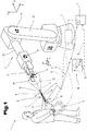
- FIG. 1 an embodiment of a control system 1 for an industrial robot 2 is illustrated schematically and by way of example.
- a control system 1 in which a manually guided movement specification means 3 is used to generate control instructions for the industrial robot 2, a programming or specification of movements or processes of the industrial robot 2 is made possible.
- This industrial robot 2 can be formed by a multi-axis manipulator unit known from the prior art or by some other handling unit with which technical processes, for example welding or painting processes or handling processes for workpieces, can be carried out in an automated or partially automated manner.
- Such an industrial robot 2 represents a preferred embodiment of a machine to be controlled according to the invention.
- At least one integrated and / or external control device 4, 4 ′ is assigned to the at least one industrial robot 2 within the control system 1.
- the control system 1 can be formed by any electrotechnical control devices 4, 4 ′ known from the prior art, it being possible for central and / or decentralized control architectures to be used depending on the technological requirements.
- a distributed control system 1 can be set up in order to be able to implement the respective control sequences for a multi-axis industrial robot 2.
- a mobile hand-held terminal 5 shown in dashed lines can be provided.
- Such a mobile hand-held terminal 5 has a high functional density or variety of functions and represents a relatively highly developed, portable operating and monitoring device for the respective control processes in the control system 1.
- the manually operated movement specification means 3 can have at least one safety switching device 6, in particular at least one consent button or a corresponding input or actuation means, which is provided for signaling the operator's consent to the execution of potentially dangerous movements or sequence changes.
- the movement specification means 3 to be guided manually in the room is constructed as light and compact as possible, preferably designed like a pen or also like a pistol in order to be intuitive and to achieve the most convenient possible motion specification with respect to the industrial robot 2.
- the movement specification means 3 can have various input and output elements, for example buttons, switches, light-emitting diodes and / or a small display 7.
- at least one manually operated control element 8 for example in the form of at least one pushbutton switch, a 4-quadrant pushbutton element, an adjusting wheel, a rocker switch, a miniaturized joystick or the like, can be implemented on the manually guided movement specification means 3.
- This operating element 8 enables the operator to interact with the control system 1 or to influence movements or processes of the industrial robot 2 or of another multi-axis controllable machine.
- the movement specification means 3 is basically freely movable in space, in particular held in the hand of the operator during the control-related movement specification and thus implemented as a whole in a position-variable manner.
- the movement specification means 3 can have an integrated sensor system 9 and / or the manually guided movement specification means 3 can be assigned an external sensor system 10 via which the orientation and / or the position of the manually guided movement specification means 3 in space is determined or evaluated will.
- the information or data of the integrated and / or external sensor system 9, 10 then represent at least some of the data or control commands that are used or required for the motion control or sequence programming of the industrial robot 2.
- the movement specification means 3 can exclusively comprise an integrated sensor system 9 and thus quasi as an active movement specification means 3 act.
- the movement specification means 3 can also be designed to be passive, with the corresponding orientation and / or position data being determined via an external sensor system 10 or their change over time being recorded.
- a combination of integrated and external sensors 9, 10 is also possible in order to achieve, for example, a particularly reliable or highly accurate determination of orientation or position data of the movement specification means 3 in relation to the three-dimensional space.
- sensor system 9, 10 is to be understood as meaning, in addition to the actual sensor-based detection means, also a corresponding evaluation means, in particular an electronic processing and evaluation device, which converts the signals or information detected by sensors into data that can be used or further processed by the control components of the control system 1. Interface protocols transferred.
- the respective sensor system 9, 10 can be formed by any detection and evaluation means known from the prior art in order to determine or determine the orientation and / or the position of objects in space using data or control technology.
- inertial sensor systems can be provided for this purpose, which preferably define the sensor system 9 integrated in the movement specification means 3.
- these inertial sensors which can consist of inertial encoders, in particular acceleration sensors and rotary angle encoders, and possibly magnetic field sensors, a computer-aided determination of orientation or position data and their change can be undertaken.
- the sensor system 9, 10 can also include triangulation methods known from the prior art for transmitted signals with a specific transit time, optical image data acquisition with the aid of video cameras, and other position acquisition systems, such as GPS or local position acquisition systems. It is important that the sensor system 9 and / or 10 embodied in each case enables a sufficiently precise and reliable determination of the orientation and / or position of the movement specification means 3 to be guided manually.
- the movement specification means 3 is more or less like a virtual handle for the end effector of the industrial robot 2 acts and the changes in position and direction of the movement specification means 3 are transformed into similar movements of the industrial robot 2.
- control commands which are based on a specification by the manually guided movement specification means 3, are converted by the industrial robot 2 essentially without delay, in particular in real time, into corresponding movements or process changes.
- One of the prerequisites for the implementation of the operator-side movement specifications by the industrial robot 2 is that the movement or sequence change specified by the operator, taking into account predefined technical restrictions of the industrial robot 2, such as a structural or environmental-related accessibility of positions or orientations, or a technically achievable, or a safety-technically permissible, maximum speed of axes or control elements of the industrial robot 2 is technically feasible.
- the executed movement of the industrial robot 2 should also largely correspond to the actual will of the operator in all situations and it is therefore an aspect of the specified measures that identifiable interference or discrepancies are checked automatically or with the aid of automation and, if necessary, compensated.
- the sensor system 9 integrated in the manually guided movement specification means 3 or the movement specification means 3 per se and / or the external sensor system 10 has at least one data interface 11, 12, via which at least data for motion control or sequence programming via at least one associated Data connection 13, 14, 15 are transmitted directly or indirectly to the control device 4, 4 ', which control device 4, 4' is used to change states of the industrial robot 2, as shown in FIG Fig. 1 has been illustrated schematically, is formed.
- the data connection 13 can be designed as a direct connection between the sensor system 9 or the movement specification means 3 and the control device 4, or - as shown schematically - as an indirect data connection 14 via an intermediate or base station or control device 4 'connected upstream of the control device 4 being.
- an indirect data connection 15 can also be provided, which, starting from the external sensor system 10, runs via one or more electronic intermediate or base stations or control devices 4 ′ to the control device 4 of the industrial robot 2.
- the data connections 13, 14 and 15 can be wired or wireless, in particular on a radio basis. It is essential that the acceleration and / or angle of rotation values determined by the sensor system 9 and / or the orientation or position data of the movement specification means 3 determined by the sensor system 10 via a suitable data connection 13, 14 or 15 to the control device 4, 4 ' are transmitted and are at least partially used or further processed by this before the corresponding control commands or control commands of the movement specification means 3 are executed by the industrial robot 2.
- control commands emanating from the manually guided movement specification means 3 are only implemented by the industrial robot 2 if, at the same time, the safety switching device 6, in particular at least one enabling button or a functionally corresponding input or actuation means, is activated on the movement specification means 3 by a Operator is manually operated in such a way that consent to the execution of potentially dangerous movements or consent to change of potentially safety-critical processes of the industrial robot 2 is signaled.
- This signaling is triggered by the operator by actuating the safety switching device 6 and recognized by the control system 1 or by the movement specification means 3 or the control device 4, 4 'as active or conscious consent to the execution of potentially dangerous actions. In this way, above all, unintentional or unintentional triggering of actions or unintentional initiation of movements of the industrial robot 2 are avoided to a large extent.
- the data connection 14 between the sensor system 9 integrated in the movement specification means 3 and the control device 4 or 4 ' can be implemented by a radio connection.
- These transmitting and / or receiving devices can be formed by devices corresponding to the Bluetooth, WLAN or ZigBee standard and by similar wireless data transmission systems known from the prior art.
- the data interface 11 is provided in or on the movement specification means 3 for establishing a wired or wired data connection.
- the data interface 11 and the further data interface corresponding therewith are formed by electrical line interfaces, between which a cable connection is established, as indicated by dash-dotted lines.
- a movement specification means 3 thus has at least one means or at least one means, in particular the internal and / or external sensors 9 or 10, is assigned to the movement specification means 3, which means for determining the orientation and / or position of the Movement specification means 3 is formed in space.
- This information can be used to design the effect of a previously mentioned operating element 8 for the positioning of an industrial robot 2 or a machine tool as a function of the orientation and / or position of the movement specification means 3.
- a movement of the movement specification means 3 or the deflection of an operating element 8 on the movement specification means 3 in a certain direction leads to an axis movement in the same direction according to the deflection.
- movements of the movement specification means 3 can also be converted directly or in scaled form into a corresponding movement of the industrial robot 2. This is comparable to guiding the industrial robot 2 with a handle virtually attached to it.
- Such movement specification means 3 enable a very simple and intuitive positioning of the axes or effectors of industrial robots 2 and can save the user from thinking and operating in different, switchable coordinate systems. This is of particular benefit to people who only have to carry out occasional or very simple adjustments.
- the robot paths for assembly or painting work on vehicle parts are often precalculated or created in advance and offline with appropriate CAD software, so that only simple adjustments for a few reference points need to be made directly on the production line.
- a safety switching device 6 in the form of at least one so-called consent button is provided on the movement specification means 3, which consent button is to be actuated during an operating process to trigger or release a potentially dangerous movement in order to thereby initiate the movement or to activate the drives.
- an electromechanically designed consent button is to be transferred by the operator from its rest position to a first actuation stage and held there during the movement. If the enabling button is used again, for example in a dangerous situation released so that it returns to the non-actuated state, or transferred by the operator to a second actuation stage or into a second actuation state by means of convulsively increased pressure, the movement is stopped immediately.
- the sensor system 9 used in the movement specification means 3 is formed by what is known as an inertial sensor system
- discrepancies between the specified values via the movement specification means 3 and the actual values of the industrial robot 2 can gradually arise in the spatial orientation of the movement specification means 3 determined by the control system 1.
- inertial sensors detect acceleration forces, i.e. function as acceleration detectors, and based on the detected acceleration values, conclusions are drawn about the distance covered or the movement and / or orientation in space.
- the orientation information to be determined relating to the movement specification means 3 can therefore be generated by the control system 1 or by at least one of its control devices 4, 4 ′ from sensory inputs of the sensors 9 integrated in the movement specification means 3 and their computational further processing.
- Intertial sensors which may be used in the movement specification means 3 are used to measure translational and rotational acceleration forces. By combining several inertial sensors to form an inertial measurement unit (IMU; Inertial Measurement Unit), the accelerations can be measured in relation to the six freedoms or degrees of freedom.
- the sensor system 9 is expediently designed as an inertial measuring unit (IMU), which usually comprises translation sensors for detecting the linear acceleration and rotation rate sensors for measuring the angular velocity.
- IMU inertial measuring unit
- the translational movement or change in movement can be calculated by means of the acceleration sensors while the respective rotational movement of the movement specification means 3 can be calculated via the rotation rate sensors.
- the translation sensors and / or the yaw rate sensors can be arranged orthogonally so that they can detect the respective accelerations in the direction of the x, y or z axes or around the x, y or z axes.
- magnetic field sensors in particular compass sensors, can additionally be used.
- the possibly provided external sensor system 10 can in particular comprise a camera system with downstream image evaluation and / or a detection system based on runtime calculations for determining the position and / or orientation of the movement specification means 3 in space, in particular its so-called pose or spatial location.
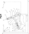
- the movement specification means 3 has at least one imaging sensor 16 and / or at least one distance-sensitive sensor 17. In particular, it can be provided that either only at least one imaging sensor 16 or only one distance-sensitive sensor 17 is provided. According to the execution according to Fig. 2 Both at least one imaging sensor 16 and at least one distance-sensitive sensor 17 are implemented.
- the imaging sensor 16 in or on the movement specification means 3 is typically formed by a camera unit 18 or a so-called CCD module.
- the at least one distance-sensitive sensor 17 can expediently be formed by a short-distance distance sensor in the form of an ultrasonic sensor, a light reflection sensor, a magnetic field sensor or an RFID sensor or transponder reader. In order to be able to determine 3D coordinates or three-dimensional relative positions, it can be useful if such a distance-sensitive sensor 17 has at least three individual sensors spaced apart from one another, as shown in FIG Fig. 2 was illustrated schematically.
- a plurality of individual sensors spaced apart from one another can form such a distance-sensitive sensor 17, the individual sensors being provided for jointly detecting a relative position with respect to at least one reference mark 19, 19 ', 19 ".
- at least one distance-sensitive sensor 17 for the data acquisition of the characteristic or the identifier or the data of such reference marks 19, 19 ', 19 ′′ being provided
- the imaging sensor 16 can, however, also be provided for the data acquisition of the characteristic or the identifier or the data of such reference marks 19, 19 ', 19 ".
- the at least one imaging and / or distance-sensitive sensor 16, 17 is provided for detecting at least one reference mark 19, 19 ', 19 "on the industrial robot 2 or on a machine to be moved or its machine part
- the reference mark 19, 19 ', 19 "to be detected in each case used sensor 16, 17 can be understood in the form of a data-technical identifier or a machine-readable information carrier.
- such a reference mark 19, 19 ', 19 "to be detected by the respectively used sensor 16, 17 can be designed as a two-dimensional marking, for example as a barcode or QR code Alternatively or in combination with this, such a reference mark 19, 19 ', 19 ′′ can also be used as a 3D marking, in particular as a three-dimensional body, such as a cuboid or a tetrahedron 20 - Fig. 2 - be executed.
- a plurality of such reference marks 19, 19 ′, 19 ′′ are preferably arranged or fastened in a distributed manner on the machine to be controlled or on the industrial robot 2 to be controlled an optically or otherwise sensorially detectable reference marking 19, 19 ', 19 "is assigned.
- Fig. 1 it is illustrated to assign one or more reference marks to the end effector 24, in particular to the respective tool, such as a welding torch, a gripping instrument, a painting device or the like. It is expedient to have at least one, in particular all of the machine parts or articulated arms 21, 22, 23 of the industrial robot 2 (and, if necessary, a workpiece not shown in the figure and moved by the industrial robot 2) that can move in rotation or in translation, each have a reference mark 19, 19 '. .
- a coupling condition 25 is defined in a first or initial method step using image-based and / or distance-based data from the relative position between the movement specification means 3 and the respective reference mark 19, 19 ', 19 ′′.
- Such a coupling condition 25 is exemplified in FIG Fig.
- Such a coupling condition 25 between the movement specification means 3 and the selected reference mark 19, 19 ', 19 ′′ can be defined as a rigid coupling condition 25 or by a coupling condition 25 that is articulated by certain degrees of freedom no mechanically rigid coupling or no physical connection is provided between the movement specification means 3 and the respective machine part or industrial robot 2.
- a defined coupling condition 25 is established in a first or initial step the machine part carrying the corresponding reference mark 19 or 19 'or 19 "or a respective articulated arm 21, 22, 23 is then tracked during a movement of the movement specification means 3 in such a way that, within the technical limits of the machine or the machine part, the in the first Verfa
- the coupling condition 25 specified in the second step is adhered to or adhered to as best as possible.
- industrial robots 2 or their articulated arms 21, 22, 23 are subject to technical limits with regard to their kinematics, dynamics and permissibility of the movements.
- control-technical tracking of the machine part or articulated arm 21, 22, 23 carrying the respective reference mark 19, 19 ', 19 "according to the following or second method step using image-based or distance-based data and / or from Data from the sensor system 9 integrated in the movement specification means 3, in particular from inertial or acceleration sensors, and / or from data from the external sensor system 10 for determining the Position or change of position of the movement specification means 3 takes place.
- This control-technical tracking of the industrial robot 2 or of at least one of its articulated arms 21, 22, 23 based on data from the internal sensor system 9 and / or the external sensor system 10 has already been explained in detail above.
- the already mentioned, motion-rigidly coupled, virtual connection 26 can also be provided, as shown in FIG Fig. 2 was symbolized with a dash-dotted line.
- additional secondary conditions either automatically, or through a user input on the movement specification means 3 or on the mobile handheld terminal 5, or on a stationary control panel can be set.
- a secondary condition can be defined by the fact that the orientation of a certain movable machine part in space is to be maintained during the tracking, or that the position of a point in space linked to a movable machine part is to be unchanged, or that both the position and the orientation of a moving machine part is to be kept constant.
- Such secondary conditions can be selected or preset, for example, via the operating elements 8 on the movement specification means 3.
- Such secondary conditions can, however, also be permanently linked to the identity of a coded reference mark 19, 19 ', 19 "and several markings that can be clearly distinguished by the user, e.g. by color or by symbols, can be arranged on a dedicated machine part, so that by the selection of a specific reference mark 19, 19 ', 19 "from this
- a plurality of reference marks 19, 19 ′, 19 ′′ on a dedicated machine part or articulated arm 21, 22, 23 can automatically be used to select the corresponding secondary conditions. This enables control elements to be saved and can also be used to work quickly and intuitively.
- the tracking of the movable machine part in the course of the second or subsequent method step only takes place during or after a release command by the operator, in particular only during the actuation of a movement coupling command button or a safety switching device 6 in the manner of a release or consent button.
- a reference mark 19, 19 ′, 19 ′′ can be selectively selected by the user in the course of reading in for the definition of the coupling condition 25 by an operator positioning the movement specification means 3 in such a way that the imaging or distance-sensitive sensor 16, 17 encodes the respective required reference mark or the respectively desired reference mark 19, 19 ', 19 "detected or can detect.
- reference marks 19, 19 ′, 19 ′′ are designed to be distinguishable in terms of sensors and control technology in order to draw control-related conclusions about the respective attachment position on the machine or on the machine part make possible.
- the reference marks can include machine-readable information, in particular encoded information such as barcodes.
- plain text information which can be read via the imaging sensor 16 and a downstream OCR acquisition or OCR evaluation.
- the information of the reference marks 19, 19 ', 19 "can per se include the relevant data and / or represent technical data links to underlying data records.
- a reference mark 19, 19 ', 19 is linked to properties and information in terms of data technology.
- the operator is signaled via an output means of the movement specification means 3, in particular via its display 7 or some other visually perceptible output means, when the imaging or distance-sensitive sensor 16, 17 has a reference mark 19, 19 ', 19 ".
- This makes it possible to indicate whether the reading in of a reference mark 19, 19 ', 19" aimed at by the operator or provided for selection was actually successful.
- Coupling condition 25 can expediently take place via a subsequent actuation of an input or actuation means, in particular a specific operating element 8 on the movement specification means 3.
- the relative position from which the coupling condition 25 is or can be established is limited in a technically defined manner. This can be done in particular by a defined limited distance between the reference mark 19, 19 ', 19 "and the movement specification means 3, or by a direction specification within a certain spatial segment with respect to the reference mark 19, 19', 19" and / or with respect to the Movement specification means 3 be defined.
- the reference mark 19 or at least one of multiple reference marks 19, 19 ', 19 is formed by a 2D marking in the form of a barcode, a symbol, a graphic or a unique, random pattern.
- the reference mark 19 or at least one of multiple reference marks by a 3D marking in the form of a cuboid, a tetrahedron 20, in the form of Cartesian pointer axes, or in the form of another 3D object on the controlled machine to be moved is formed.
- the movement specification means 3 is designed in the form of a rod or strip, wherein it can have a length 28 between 10 cm and 100 cm.
- the at least one imaging sensor 16 or the at least one distance-sensitive sensor 17 is expediently arranged at an end of the movement specification means 3 facing away from a handle end or handle section 36, as shown in FIG Fig. 2 was indicated schematically.
- the movement specification means 3 is designed for contactless, distance-affected movement coupling with respect to the machine to be controlled or a selected machine part, with a distance 29 between the movement specification means 3 and the machine and the machine part can have a distance value selected from a range between 20 cm and 200 cm.
- the virtual coupling or the initially established coupling condition 25 is computationally modeled as an elastically flexible, mechanical connection 26, 27.
- This computational model formation is preferably carried out within the control device 4, 4 '.
- the respective computational modeling can use the previously explained rigidly coupled connection 26 - Fig. 2 - or, above all, adjust or calculate the articulated connection 27 explained above on the basis of a model.
- the external sensor system 10 can be defined by a plurality of spatially distributed cameras 30, 31, 32. At least three cameras 30, 31, 32 are preferably provided, the relative position of which is defined to one another or whose respective position and orientation in space are defined and known from the control side. Using the respective image data of these cameras 30, 31, 32 recording the work area of the industrial robot 2 and the operator, or via the respective image sequences, the respective actual position or orientation and position of the movement specification means 3 in space can then be determined in a manner known per se can be calculated. These calculations can in principle be carried out by means of the internal and / or external control device 4, 4 ′ of the robot control system 1.
- the movement specification means 3 can be formed by a standard available, commercially available smartphone or by a tablet PC, on which components the corresponding software for implementing the specified method is executed.
- FIG. 3 a further embodiment of a control-technical movement specification means 3 to be guided by an operator for influencing movement or for so-called teaching of an industrial robot 2 or a similar machine is schematically illustrated.
- movements of the movement specification means 3 are converted into corresponding movements of the industrial robot 2.
- the movement specification means 3 can be supported on the machine to be controlled, in particular on moving parts or on the parts to be moved or articulated arms 21, 22, 23.
- the corresponding movement specification means 3 has at least one elastically flexible contacting and spacing element 33.
- This contacting and spacing element 33 is for contacting or touching a machine part that is coupled by control technology, for example according to the articulated arm 22 of the industrial robot 2, in the vicinity of or in the vicinity of the respective reference mark 19, 19 ', 19 ", for example in the vicinity or detection area of the reference mark 19'
- this power transmission or the mechanical contact or the load-transferring support of the movement specification means 3 on the machine part to be moved for example according to the articulated arm 22, the operator, i.e. the person who does the movement
- the control device 3 guides or maintains a haptic feedback in relation to the machine movement ultimately carried out by the control device 4, 4 '.
- This touch or support and contacting of the motion specification means 3 on a surface of the selected machine part or articulated arm 21, 22, 23 can expediently be non-conductive, in particular electrical be made insulating. In any case, an electrically conductive connection between the movement specification means 3 or between its contacting and spacing element 33 or the sensor head 37 and the respective machine part, for example the articulated arm 22, is not absolutely necessary or not necessary.
- the elastically flexible contacting and spacing element 33 can comprise a telescopic or variable-length coupling rod 34 and / or a buffer element 35, which buffer element 35 has a contact surface 38 that increases friction compared to metal or plastic surfaces of the industrial robot 2, for example made of an elastomeric plastic can.
- variable-length coupling rod 34 this can be defined by rod elements which can be adjusted telescopically with respect to one another.
- a buffer element 35 or a corresponding sensor head 37 is formed, an elastically resilient or a mechanical coupling and force transmission with a certain mechanical interaction between the user or the operator and the respectively executed movements of the industrial robot 2 can be established. In particular, this ensures haptic feedback for the operator, so that the operator ergonomics and the achievable precision of the movement in connection with the correspondingly executed movement specification means 3 are promoted.
- the probe or sensor head 37 which is mounted either resiliently or elastically resiliently at an end opposite a handle section 36 of the movement specification means and / or is linearly adjustable or telescopically adjustable and / or resiliently resetting in some other way or relative to the handle section 36 of the movement specification means 3 is adjustable, can have or carry the at least one imaging sensor 16 and / or the at least one distance-sensitive sensor 17.
- the distance-sensitive sensor 17 can in particular be defined by an RFID reader, by a magnetic field sensor, or by another distance-sensitive sensor. It is essential that the respective distance-sensitive sensor 17 in the movement specification means 3 detects or can detect the corresponding reference mark 19, 19 ', 19 ", for example the reference mark 19' on the articulated arm 22 to be moved.
- the sensor head 37 comprises an imaging sensor 16 in the manner of a CCD module or a miniature video camera in order to be able to detect or record the optical information or properties of an optical reference mark 19, 19 ', 19 ".
- the imaging sensor 16 or the distance-sensitive sensor 17 in the sensor head 37 is expediently connected to an electronic evaluation device 39 in the movement specification means 3, in particular by a line.
- the electronic evaluation device the respective signals of the sensors 16 and 17 are either preprocessed or processed and evaluated for the most part.
- the industrial robot 2 are transmitted.
- an output means in the form of a display 7 can be provided on the movement specification means 3.
- at least one input element for example in the form of an operating element 8 and / or a safety switching device 6, can be formed on the movement specification means 3.
- one or more miniaturized cameras that is to say imaging sensors 16, are formed in particular at the end of a rod, for example at the end of a telescopic or variable-length coupling rod 34.
- machine-readable reference marks 19, 19 ', 19 " are formed from one another in terms of data technology. Codes or the like can be formed and glued directly to the respective machine components.
- the control software By pressing a command button, for example an operating element 8 on the movement specification means 3, the control software records an image of the reference marking 19 'and then the distance and the position to the camera or to the imaging Sensor 16, in particular to the probe or sensor head 37. These data are used as a reference for the further target positions or target poses of the industrial robot 2.
- the respective image or reference marks 19, 19 ', 19 can also Contain information about the point or position at which the industrial robot 2 is virtually is held or coupled so that the control software of the control device 4, 4 '- Fig. 1 , 2 - Calculate the kinematic movements of the industrial robot 2 and then carry out or track them accordingly.
- At least one Light source 40 in particular a lighting device for improving the image recordings of the camera or the imaging sensor 16, is formed.
- the industrial robot 2 or its articulated arm 2 executes those movements that are carried out by means of the movement specification means 3.
- the industrial robot 2 or its control device 4, 4 maintains the mechanical contact or the contact between the probe or sensor head 37 and the respective machine part or is brought about that a mutual Support or contact force is maintained or is maintained as best as possible.
- the initially selected and recorded reference mark 19, 19 'or 19 "can be used as an additional control aid or the reference mark 19' selected in the introductory step functions - as in the exemplary embodiment according to FIG. Fig. 3 has been illustrated schematically - at least for the simple selection or selection of that machine part of the industrial robot 2, for example the articulated arm 22, with which an interaction with the operator or the movement specification means 3 is desired.
- the respective reference marks 19, 19 ′, 19 ′′ can effect additional control functions, such as switching modes, performing an axle lock function, and the like and also be designed to be more fail-safe.
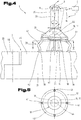
- FIG. 4 is a further embodiment of a practicable control method or a subcomponent of the control system 1 for implementation in the specified Control system 1 illustrates.
- an expedient embodiment of a movement specification means 3 to be guided or adjusted manually by an operator schematically illustrates which movement specification means 3 can advantageously be used or implemented as a subcomponent for implementing the specified control method and control system 1.
- the corresponding movement specification means 3 comprises a contacting and spacing element 33 which is formed by at least two, in particular three or four, elastically flexible support elements 41.
- these support elements 41 are designed to be foot-shaped or columnar, these support elements 41 having an elastically flexible mobility or a resiliently resilient adjustability.
- these support elements 41 can be defined by an elastomeric plastic with fold-like or film hinge-like shapes or by at least one knee joint.
- the support elements 41 can also be designed in the form of helical or leaf springs. It is essential that the respective support elements 41 as a whole have an elastically flexible or resiliently resilient contacting and spacing element 33 for the movement specification means 3 in relation to a surface of the articulated arm 21 to be moved, 22, 23 define.
- the respective support elements 41 have arcuate bulges or hinge-like joint sections which allow a relative adjustment of the movement specification means 3, in particular of its at least one sensor 16, 17 with respect to the reference mark 19, 19 ', 19 "which is fixedly moved on the respective joint arm 21, 22, 23" make possible.
- the corresponding support arms or support elements 41 can be formed from an elastomeric material that increases friction with respect to the surface of the industrial robot 2.
- the respective support elements 41 can also have contact feet 42, which enable mechanical contacting of the movement specification means 3 on the industrial robot 2 or at the respectively desired position of the articulated arms 21, 22, 23 with the most slip-proof possible.
- these contact feet 42 can also be defined by suction cups, which on the one hand can provide a particularly non-slip support, but on the other hand also an easily detachable and reactivatable coupling between the movement specification means 3 and the respective articulated arm 21, 22, 23. It is useful if the movement specification means 3 is at least approximately is positioned axially central or centric to the respective reference mark 19, 19 ', 19 ". An absolutely axially aligned centering or alignment of the movement specification means 3 with respect to the reference mark 19, 19', 19" to be read in or referenced is not necessary.
- FIG Fig. 5 it is alternatively also possible to provide an annular or tubular, elastically flexible support body 43, as shown in FIG Fig. 5 was indicated schematically with dashed lines.
- the sensor system in the movement specification means 3 is also positioned in a supported manner in a certain relative position with respect to the reference mark 19, 19 ', 19 ′′ to be read or detected, and is basically supported largely without tremors 43 can include defined areas of weakness, breakthroughs and / or expansion or compression folds in its jacket section to achieve sufficient elastic resilience, which allow a spatial relative adjustment of the at least one sensor 16, 17 of the movement specification means 3 relative to the respective reference mark 19, 19 ', 19 " on the respective articulated arm 21, 22, 23.
- this ring-shaped or tubular support body 43 which is adjustable in a plurality of spatial directions, surrounds or at least partially delimits the reference mark 19, 19 ', 19 "to be detected when the movement specification means 3 for control purposes on the respectively selected articulated arm 21 , 22, 23.
- Such an annular or tubular support body 43 can also preferably have a friction-increasing adhesive effect on its contacting surface 38 with respect to the typically metallic surfaces of the industrial robot 2 or its articulated arms 21, 22, 23.
- the at least one distance-sensitive or imaging sensor 16, 17 of the movement specification means 3 is in different relative positions compared to that of the operator as a result of the application of a positioning force on the part of the operator
- the reference mark 19, 19 ', 19 "attached to the respective articulated arm 21, 22, 23 can be moved.
- These relative adjustments are such that preferably in each of the relative adjustment positions that can be assumed, at least a section of the reference mark 19, 19', 19" to be detected by the sensor 16 or 17 is detectable or remains detectable.
- Fig. 4 is a rotationally deflected adjustment position of the movement specification means 3 has been indicated in dashed lines.
- the movement specification means 3 In addition to or in combination with such rotary or tilting adjustment movements of the movement specification means 3 relative to the reference mark 19 to be detected, it is also possible for the movement specification means 3 to carry out translational relative adjustments or to be able to be carried out by the operator.
- the movement specification means 3 enables rotational adjustment movements about its longitudinal center axis 44 and / or axial adjustment movements with regard to its longitudinal center axis 44 and / or radial adjustment movements with regard to its longitudinal center axis 44 and / or tilting movements with regard to its longitudinal center axis 44, such as this in Fig. 4 was indicated with the various double arrows.
- the at least one sensor 16, 17 of the movement specification means 3 can detect the respective relative displacements or relative displacements with respect to the reference mark 19, 19 ', 19 ′′ to be detected
- the reference mark 19, 19 ', 19 is an optically detectable identifier or reference mark, such as a graphic pattern in the form of a QR code or the like, relative adjustments or travel ranges in recorded in a simple manner and then converted into corresponding actuating movements or control commands for the industrial robot 2.
- the corresponding conversions of the sensory values of the movement specification means 3 into corresponding adjusting movements of the industrial robot 2 are expediently carried out via the control device 4, 4 '.
- the elasticity of the foot-like support elements 41 or of the hollow-profile-like support body 43 is preferably selected such that the movement specification means 3 returns to its original starting or rest position, in particular axially aligned or at least approximately centric, after the operator has lost the actuating or adjusting forces is aligned to the respectively assigned reference mark 19, 19 ', 19 ".
- the annular or tubular support body 43 can be formed in the manner of a corrugated pipe with a plurality of beads or movement ribs, which on the outer surface of the support body 43 in the circumferential direction the lateral surface run.
- the position data that are recorded by the at least one sensor 16, 17 of the movement specification means 3 in relation to the reference mark 19, 19 ', 19 ′′ are optionally processed within the movement specification means 3 and via the at least one data interface 11, which, as previously, has already been carried out , can be wired or wireless, transmitted to the control device 4, 4 'and converted by this into corresponding control commands or movement movements for the industrial robot 2 or the respective articulated arm 21, 22, 23.
- an articulated arm 21, 22, 23 of an industrial robot 2 has a mechanical support structure 45, in particular at least one mechanical arm.
- the articulated arm 21 is via at least one axis of rotation 46 relative to the adjacent articulated arm 22 or relative to another mechanical component of the industrial robot 2 with adjustable angles.
- servomotors or other drive elements such as, for example, hydraulic actuating cylinders, are provided in or on the industrial robot 2, as is known per se.
- the support structure 45 of an articulated arm 21, 22, 23 is typically made of metal, but can also be made of plastic, the respective surface of the support structure 45 optionally having friction-increasing sections in order to support the movement specification means 3 or its contacting and contacting means as non-slip as possible To achieve spacing element 33.
- the reference marks 19, 19 ', 19 ′′ are formed by stickers with printed identifications or codes or structures "and the movement specification means 3 can be achieved and the change in the relative position over time can also be determined.
- the use of RFID tags is also conceivable in order to be able to record relative positions or to be able to detect changes in relative positions.
- An advantageous property of the specified movement specification means 3 is that it enables a simple selection of those articulated arms 21, 22, 23 which are to be changed by the operator in their position or orientation, that is, in their pose.
- an adjustment process of the respectively involved articulated arm 21, 22, 23 or a plurality of for the desired adjustment movement of the required articulated arms 21, 22, 23 can be carried out by simply adjusting or moving the movement specification means 3 in the desired direction.
- the movement drive of the articulated arm 21 is activated by rotating the movement specification means 3 about its longitudinal center axis 44, and then an angular adjustment with respect to the axis of rotation 46 is initiated.
- the industrial robot 2 can be adjusted very easily and intuitively thanks to the particularly simple and practicable selection option of the respective articulated arm 21, 22, 23 by means of the reference marks 19, 19 ', 19 "attached to the articulated arms 21, 22, 23, without having to operate of complex input means, such as a so-called 6D mouse, a large number of traversing keys, etc.
- the mechanical support or direct contact between the movement specification means 3 and the respectively selected articulated arm 21, 22, 23, which is the respective reference mark 21, 22, 23 supports the operating and control behavior considerably.
- the industrial robot 2 can automatically execute the correspondingly programmed motion sequences in numerous repetitive cycles with other, similar workpieces
- robot-assisted manufacturing and joining processes for example when assembling vehicles, the joining processes including guidance of the respective components by an operator under visual control, but the components being held and moved at the same time by an assembly robot in order to carry their weight and for to enable the person to use the parts in a way that saves effort.
- the measures or procedures described above are mapped in the control system 1 or in the movement specification means 3 or can be carried out by means of these devices.
- the functions and behaviors of the control system 1 or of the movement specification means 3 are largely software-controlled, electronic ones Components determined.
- the appropriate implementation of the measures according to the invention by means of software technology is familiar to the person skilled in the art and can be carried out using standard available electronic components in conjunction with customary input and output means.
Landscapes
- Engineering & Computer Science (AREA)
- Robotics (AREA)
- Physics & Mathematics (AREA)
- General Physics & Mathematics (AREA)
- Automation & Control Theory (AREA)
- Mechanical Engineering (AREA)
- Human Computer Interaction (AREA)
- Manufacturing & Machinery (AREA)
- Manipulator (AREA)
- Numerical Control (AREA)
Description
Die Erfindung betrifft ein Verfahren zum Steuern der Bewegungen von Gelenkarmen eines Industrieroboters, ein Steuerungssystem zur Umsetzung des entsprechenden Steuerungsverfahrens, sowie ein in einem solchen Steuerungssystem einsetzbares Bewegungsvorgabemittel, wie dies in den Ansprüchen 1, 24 und 25 angegeben ist.The invention relates to a method for controlling the movements of articulated arms of an industrial robot, a control system for implementing the corresponding control method, and a movement specification means that can be used in such a control system, as is specified in
Ein verbreiteter Stand der Technik beim Teachen der Positionen von Robotern, insbesondere von Industrierobotern, sind Handbediengeräte mit Tasten oder einem Joystick, mit welchen der Roboter selbst, oder einzelne Achsen seiner Gelenksarme, verfahren werden können. Dabei können einzelne Punkte auf der entsprechenden Bewegungsbahn abgespeichert werden, um in einem nachfolgenden Automatikbetrieb die jeweilige Bewegungsbahn oftmals wiederholen zu können.A widespread state of the art when teaching the positions of robots, in particular industrial robots, are hand-held operating devices with buttons or a joystick, with which the robot itself or individual axes of its articulated arms can be moved. Individual points on the corresponding trajectory can be saved in order to be able to repeat the respective trajectory many times in a subsequent automatic mode.
Eine weitere Möglichkeit zum Einlernen bzw. Programmieren von Roboterbewegungen ist eine unmittelbare Handführung des Roboters. Entsprechend einer ersten Ausführungsform wird dabei der Endeffektor des Roboters einfach mit der Hand ergriffen und an die gewünschte Position bewegt. Entsprechend einer zweiten Ausführungsform ist vorgesehen, dass Griffe direkt an den Roboter mechanisch angekoppelt werden und zum Beispiel über eine hochgenaue Kraft- bzw. Momentenmessung die Betätigungskraft des Bedieners ausgewertet und zur Steuerung bzw. Regelung der Position des Roboters verwendet wird. Diese Ausführungen haben den sicherheitstechnischen Nachteil, dass der Benutzer sehr nahe am Roboter stehen muss, oder sich teilweise sogar unterhalb der Bewegungsarme des Roboters befindet. Bei einem Fahrfehler des Roboters bzw. bei einem Berechnungsfehler oder einem sonstigen Fehler seiner Steuervorrichtung kann der Roboter noch einen relativ großen Weg mit durchaus hoher Geschwindigkeit zurücklegen, bis ihn eine Sicherheitsüberwachung normalerweise zum Stillstand bringt. Dies kann aber ausreichend sein, um eine sich nahe befindliche Person zu verletzen. Zudem muss bei der zweitgenannten Ausführungsform die Schwierigkeit der ausreichend stabilen mechanischen Ankopplung an den Roboter überwunden werden, was Eingriffe in die Mechanik bzw. Tragstruktur des Roboters erfordert. Ein häufiges und rasches Umkoppeln des Angriffspunktes am Roboter ist damit ebenfalls kaum möglich bzw. wenig benutzerfreundlich.Another possibility for teaching in or programming robot movements is direct manual control of the robot. According to a first embodiment, the end effector of the robot is simply gripped by hand and moved to the desired position. According to a second embodiment, it is provided that handles are mechanically coupled directly to the robot and, for example, the operating force of the operator is evaluated via a highly accurate force or torque measurement and used to control or regulate the position of the robot. These designs have the safety disadvantage that the user has to stand very close to the robot, or in some cases even be below the robot's moving arms. In the event of a driving error by the robot or in the event of a calculation error or some other error in its control device, the robot can still cover a relatively long distance at a very high speed until a safety monitoring system normally brings it to a standstill. However, this can be enough to injure someone close by. In addition, in the second-mentioned embodiment, the difficulty of the sufficiently stable mechanical coupling to the robot must be overcome, which requires interventions in the mechanics or support structure of the robot. Frequent and rapid recoupling of the point of attack on the robot is therefore also hardly possible or not very user-friendly.
Die
Eine weitere bekannte Druckschrift ist die
Die
Ein Steuerungsverfahren, ein Steuerungssystem und ein Bewegungsvorgabemittel entsprechend dem einleitenden Teil der unabhängigen Ansprüche ist in der
Weitere Ausführungsformen zur möglichst einfachen Handsteuerung bzw. zur möglichst intuitiven, handgeführten Programmierung von Industrierobotern sind aus der
Aufgabe der vorliegenden Erfindung war es, die Nachteile des Standes der Technik zu überwinden und ein Verfahren bzw. eine Vorrichtung zur Verfügung zu stellen, mit welchen ein Benutzer in der Lage ist, eine einfache und intuitive Programmierung oder Ausführung von Stellbewegungen einer Maschine, insbesondere eines Industrieroboters, vornehmen zu können.The object of the present invention was to overcome the disadvantages of the prior art and to provide a method and a device with which a user is able to easily and intuitively program or execute adjusting movements of a machine, in particular one Industrial robots.
Diese Aufgabe wird durch ein Steuerungsverfahren, durch ein Steuerungssystem und ein Bewegungsvorgabemittel gemäß den Ansprüchen gelöst.This object is achieved by a control method, a control system and a movement specification means according to the claims.
Bei dem erfindungsgemäßen Verfahren bzw. System zum Steuern der Bewegungen der Gelenkarme eines Industrieroboters bzw. zum Steuern der Bewegungen von verstellbaren Maschinenteilen einer sonstigen, mehrachsigen Maschine, ist ein durch eine Bedienperson händisch zu führendes Bewegungsvorgabemittel vorgesehen, dessen Bewegungen zur Generierung von wenigstens einem Teil der Bewegungssteuerdaten für die zu steuernde Maschine bzw. den zu steuernden Industrieroboter vorgesehen sind. Unter einer händischen Führung des Bewegungsvorgabemittels ist dabei sowohl eine freie Führung im Raum, als auch eine Relativverstellung bzw. Auslenkung eines Teilabschnittes des Bewegungsvorgabemittels relativ zu einem fest bzw. lösbar montierten Teilabschnitt des Bewegungsvorgabemittels zu verstehen. Das Bewegungsvorgabemittel ist dabei mit wenigstens einer stationären Steuervorrichtung datentechnisch gekoppelt und die wenigstens eine Steuervorrichtung ist zumindest zur Aktivierung und Deaktivierung von Bewegungsantrieben der Maschine bzw. des Industrieroboters ausgebildet. Zumindest an einzelnen von der Bedienperson gesteuert verstellbaren Maschinenteilen bzw. Gelenkarmen ist dabei wenigstens eine von mehreren Referenzmarken angeordnet oder ausgebildet. Das Bewegungsvorgabemittel weist zumindest einen bildgebenden und/oder zumindest einen abstandssensitiven Sensor auf, welcher zumindest eine Sensor mit wenigstens einer der mehreren Referenzmarken in eine von der Bedienperson ausgewählte räumliche Relativposition versetzbar ist. In einem ersten bzw. initialen Schritt wird dabei unter Verwendung bildbasierender und/oder abstandsbasierender Daten aus der relativen Lage zwischen dem Bewegungsvorgabemittel und der jeweiligen Referenzmarke eine starre Koppelbedingung, oder eine um bestimmte Freiheitsgrade gelenkig gedachte Koppelbedingung definiert bzw. festgelegt. In einem nachfolgenden Schritt wird während einer Bewegung des Bewegungsvorgabemittels das die selektierte Referenzmarke tragende Maschinenteil, insbesondere der jeweilige Gelenkarm bzw. die jeweils erforderlichen Gelenkarme des Industrieroboters, steuerungstechnisch derart nachgeführt, dass im Rahmen der technischen Grenzen der Maschine oder des Maschinenteils, insbesondere im Rahmen der technischen Grenzen des angebundenen Industrieroboters, die im ersten Schritt festgelegte Koppelbedingung eingehalten oder zumindest annähernd eingehalten wird.In the method and system according to the invention for controlling the movements of the articulated arms of an industrial robot or for controlling the movements of adjustable machine parts of another multi-axis machine, a movement specification means to be performed manually by an operator is provided whose movements are used to generate at least part of the Movement control data for the machine to be controlled or the industrial robot to be controlled are provided. Manual guidance of the movement specification means is understood to mean free guidance in space as well as a relative adjustment or deflection of a section of the movement specification means relative to a fixed or detachable section of the movement specification means. The movement specification means is data-technically coupled to at least one stationary control device and the at least one control device is at least for Activation and deactivation of motion drives of the machine or the industrial robot. At least one of several reference marks is arranged or formed at least on individual machine parts or articulated arms that can be adjusted in a controlled manner by the operator. The movement specification means has at least one imaging and / or at least one distance-sensitive sensor, which at least one sensor with at least one of the plurality of reference marks can be moved into a spatial relative position selected by the operator. In a first or initial step, using image-based and / or distance-based data from the relative position between the movement specification means and the respective reference mark, a rigid coupling condition or a coupling condition that is imagined to be articulated around certain degrees of freedom is defined or established. In a subsequent step, during a movement of the movement specification means, the machine part carrying the selected reference mark, in particular the respective articulated arm or the respectively required articulated arms of the industrial robot, is tracked by the control system in such a way that within the technical limits of the machine or the machine part, in particular within the framework of the technical limits of the connected industrial robot, the coupling condition specified in the first step is complied with or at least approximately complied with.
Erfindungsgemäß ist somit eine Art virtuell bzw. semimechanisch ankoppelbares Greif- bzw. Bewegungsvorgabemittel zur Handführung von Industrierobotern geschaffen. Das Greifmittel bzw. das dementsprechende Bewegungsvorgabemittel kann dabei eine Greif- bzw. Aktivierungstaste aufweisen, sowie eventuell einen kurzen Stab zur Distanzverlängerung umfassen. Indem man das Ende des Stabes bzw. Bewegungsvorgabemittel an dafür vorgesehene Stellen des Industrieroboters oder auch des Werkstücks hält oder daran abstützt, wobei dies innerhalb einer bestimmten Toleranz zu erfolgen hat, und zudem die Greiftaste betätigt wird, kann man den Roboter bzw. einzelne seiner Gelenkarme virtuell an das Bewegungsvorgabemittel koppeln. Mit jeder weiteren durchgeführten Bewegung kann dann der entsprechende Angriffspunkt des Roboters bzw. der Industrieroboter per se automatisch den Bewegungen des Bewegungsvorgabemittels folgen, als ob man eine feste mechanische Kopplung gegenüber dem Industrieroboter hergestellt hätte. Der Industrieroboter versucht dabei, mit Hilfe seiner Steuerungsvorrichtung den Abstand bzw. die Orientierung zwischen dem Angriffs- bzw. dem Kontaktpunkt und dem Bewegungsvorgabemittel, beispielsweise gegenüber dessen End- oder Erfassungspunkt, konstant zu halten bzw. bestmöglich nachzuführen. Diese Nachführung kann dabei entsprechend einer zweckmäßigen Ausführungsform so lange erfolgen, solange die Greif- bzw. Aktivierungstaste durch die Bedienperson betätigt wird.According to the invention, a type of virtually or semi-mechanically connectable gripping or movement specification means for manual guidance of industrial robots is thus created. The gripping means or the corresponding movement specification means can have a gripping or activation button and possibly a short rod for extending the distance. By holding or supporting the end of the rod or movement specification means at designated points on the industrial robot or the workpiece, this being done within a certain tolerance, and also pressing the pushbutton, the robot or some of its articulated arms can be operated virtually couple to the movement specification means. With every further movement carried out, the corresponding point of attack of the robot or the industrial robot per se can then automatically follow the movements of the movement specification means, as if a fixed mechanical coupling to the industrial robot had been established. The industrial robot tries, with the help of its control device, to keep the distance or the orientation between the point of attack or the contact point and the movement specification means constant or to track it as best as possible, for example with respect to its end point or detection point. This tracking can take place in accordance with an expedient embodiment as long as the gripping or activation key is actuated by the operator.
Die erfindungsgemäßen Maßnahmen begünstigen eine einfache und intuitive Programmierung oder Ausführung von Bewegungen einer Maschine, insbesondere eines Industrieroboters. Insbesondere kann dadurch das Denken in Koordinatensystemen bzw. Raumrichtungen und die Berücksichtigung der Blickrichtung der Bedienperson auf den Industrieroboter, insbesondere in Bezug auf Ansichten von vorne, hinten oder seitlich, entfallen. Ein besonderer Vorteil liegt auch darin, dass durch die sehr einfache und intuitive Selektionsmöglichkeit von einzelnen, jeweils bewegbaren Maschinenteilen bzw. Gelenkarmen eine rasche Einarbeitung in die Steuerungssystematik ermöglicht ist. Auch Fehlbedienungen hinsichtlich der gewollten Bewegungsrichtung bzw. irrtümliche Aktivierungen von Bewegungen eines nicht benötigten bzw. nicht gewünschten Gelenkarms des Industrieroboters können dadurch hintan gehalten werden. Zudem kann die Anzahl der Bedientasten bzw. die Anzahl von mehrachsigen Bedienelementen, wie z.B. Joysticks, für die Einleitung der jeweiligen Bewegungskommandos reduziert werden, was die Übersichtlichkeit und Baugröße der entsprechenden Steuerungssysteme begünstigt.The measures according to the invention promote simple and intuitive programming or execution of movements of a machine, in particular of an industrial robot. In particular, thinking in coordinate systems or spatial directions and taking into account the viewing direction of the operator on the industrial robot, in particular with regard to views from the front, back or side, can be dispensed with. A particular advantage is that the very simple and intuitive selection option of individual, respectively movable machine parts or articulated arms enables rapid familiarization with the control system. Incorrect operation with regard to the desired direction of movement or erroneous activation of movements of an unneeded or undesired articulated arm of the industrial robot can thereby be prevented. In addition, the number of control buttons or the number of multi-axis control elements, such as joysticks, for initiating the respective movement commands can be reduced, which improves the clarity and size of the corresponding control systems.
Zweckmäßig sind auch die Maßnahmen gemäß Anspruch 2, da dadurch die Erfassung der jeweiligen räumlichen Position und/oder Orientierung bzw. der sogenannten Pose des Bewegungsvorgabemittels im Raum je nach Umgebungsbedingungen bzw. je nach geforderter Erfassungsdynamik besonders präzise und zuverlässig vorgenommen werden kann. Dabei ist beispielsweise durch eine Kombination von interner Sensorik und von externer Sensorik in Bezug auf das Bewegungsvorgabemittel eine hochgenaue und von Drifteinflüssen weitgehend befreite Posenermittlung erzielbar. Durch Verwendung der Daten des bildgebenden und/oder abstandssensitiven Sensors am Bewegungsvorgabemittel kann in einfacher und zuverlässiger Art und Weise eine bedienerseitige Veränderung der Pose des Bewegungsvorgabemittels bzw. von dessen Griffabschnitt relativ zur bekannten Position der jeweils selektierten bzw. zugeordneten Referenzmarke ausreichend exakt und zuverlässig festgestellt werden. Auch das Ausmaß solcher Auslenkungen in Form von translatorischen und/oder rotatorischen Verstellbewegungen des Bewegungsvorgabemittels relativ zur jeweils selektierten Referenzmarke kann durch abstandssensitive bzw. bildgebende Sensoren optimal detektiert werden.The measures according to
Vorteilhaft sind auch die Maßnahmen gemäß Anspruch 3, da dadurch eine für die Bedienperson klar nachvollziehbare Bewegungskopplung zwischen dem Bewegungsvorgabemittel und der zu steuernden Maschine bzw. dem virtuell jeweils angekoppelten Maschinenteil vorliegt. Insbesondere kann dadurch ein eindeutiger visueller Vergleich zwischen Bewegungsvorgabe und Bewegungsausführung durch die entsprechend gesteuerte Maschine vorgenommen werden. Derartige starre Koppelbedingungen unterliegen dabei natürlich gewissen Grenzen, unter anderem hinsichtlich der jeweiligen Kinematik und Bewegungsdynamik der angesteuerten Maschine bzw. des angesteuerten Industrieroboters.The measures according to
Zweckmäßig ist auch eine Ausführung gemäß Anspruch 4, da dadurch eine in Bezug auf die erzielbare ergonomische Führung des Bewegungsvorgabemittels verbesserte Ausführung geschaffen ist. Beispielsweise bei relativ weitreichenden linearen Verstellbewegungen eines Maschinenteils bzw. des Endeffektors eines Industrieroboters kann die Bedienperson dennoch an einem Standort verbleiben, während der Endeffektor relativ weitreichende Verstellbewegungen ausführt.An embodiment according to
Durch die Maßnahmen gemäß Anspruch 5 kann ein vielfältiges Eingriffs- bzw. Steuerungsverhalten selektiv voreingestellt werden und kann darüber hinaus die Diskrepanz zwischen den Vorgaben der Bedienperson und der letztendlichen Bewegungsausführung von Seiten der Steuervorrichtung bzw. des Industrieroboters möglichst gering gehalten werden.By means of the measures according to
Von Vorteil sind auch die Maßnahmen nach Anspruch 6, da dadurch ein Industrieroboter beispielsweise derart geführt werden kann, dass dessen Endeffektor bzw. der jeweils ausgewählte Gelenkarm entweder nur translatorische Bewegungen ausführt, oder nur rotatorische Bewegungen, beispielsweise um den TCP. Oder der Endeffektor bleibt überhaupt stehen, während nur die Lage eines Ellenbogengelenks des Industrieroboters verändert wird. Dadurch kann die Führung des Bewegungsvorgabemittels für die Bedienperson erheblich erleichtert werden, nachdem eine absolut exakte Führung des Bewegungsvorgabemittels nicht notwendig ist. Die Auftrennung in Wirkrichtungen bzw. die Filterung in Bezug auf translatorische oder rotatorische Bewegungen können auch ungewollte Verstellbewegungen des Industrieroboters vermieden werden.The measures according to
Durch die Maßnahmen gemäß Anspruch 7 kann in einfacher und effektiver Art und Weise die Sicherheit des Steuerungssystems gesteigert werden. Insbesondere können dadurch unbeabsichtigte Auslösungen von Verfahrbewegungen des Industrieroboters hintan gehalten werden.The security of the control system can be increased in a simple and effective manner by the measures according to
Von Vorteil sind auch die Maßnahmen nach Anspruch 8, da dadurch eine einfache und überaus intuitive Art und Weise zur Auswahl einer für eine Bewegung bzw. Positionsveränderung vorgesehenen Maschinenteils bzw. Gelenkarms bewerkstelligt bzw. angeboten ist. Zusätzlich zur einfachen Selektion des für eine Verstellung bzw. Positionsveränderung vorgesehenen Maschinenteils kann quasi der virtuelle Angriffspunkt des Bewegungsvorgabemittels aufgebaut werden, um eine intuitive Verstellbewegung des zuvor ausgewählten Maschinenteils bzw. Gelenkarms letztendlich auch aus- bzw. durchführen zu können. Darüber hinaus sind die jeweiligen Maßnahmen hinsichtlich der erforderlichen Komponenten relativ einfach bzw. kostengünstig implementierbar. Der entsprechende Auswahlvorgang kann dabei eine vorausgehende oder abschließende Bedienhandlung in Art eines Tastendrucks am Bewegungsvorgabemittel umfassen. Dies ist aber nicht zwingend erforderlich, denn grundsätzlich genügt die bloße Erfassung einer selektierten Referenzmarke am jeweils gewünschten, zur Bewegung vorgesehenen Maschinenteil bzw. Gelenkarm.The measures according to
Zweckmäßig sind auch die Maßnahmen gemäß Anspruch 9, da dadurch die jeweilige Referenzmarke als Datenträger und/oder als Verlinkungsmittel zu einem Datensatz fungiert, um so die jeweiligen Steuerungsabläufe vereinfacht bzw. hinsichtlich der Nutzungsabläufe optimiert ausführen zu können.The measures according to
Durch die Maßnahmen gemäß Anspruch 10 können einerseits die Bedienergonomie gesteigert und andererseits auch Irrtümer bzw. fehlerhafte Annahmen seitens der Bedienperson zuverlässig hintan gehalten werden.By means of the measures according to
Von Vorteil sind auch die Maßnahmen gemäß Anspruch 11, da dadurch Informationen bzw. Daten zur Verfügung stehen, welche der Bedienperson die Evaluierung der Steuerungsabläufe bzw. der jeweils aktuellen Zustände deutlich erleichtern.The measures according to
Zweckmäßig sind auch die Maßnahmen gemäß Anspruch 12, da dadurch der Aufbau einer Koppelbedingung bewusst bzw. benutzerinitiiert zu erfolgen hat und somit Irrtümer bzw. Fehlbedienungen ausgeschlossen werden können.The measures according to
Zweckmäßig sind auch die Maßnahmen gemäß Anspruch 13, da dadurch unpraktikable bzw. hinsichtlich der virtuellen Kopplungen ungünstige Relativpositionen ausgefiltert bzw. unterdrückt werden können. Somit wird erreicht, dass die jeweils erzielbare Steuerungsgenauigkeit bzw. Bedienungsergonomie möglichst hoch gehalten wird. Auch der Einnahme von aus Sicherheitsüberlegungen nachteiligen Positionen der Bedienperson kann auf diese Weise entgegengewirkt werden.The measures according to
Auch durch die Maßnahmen gemäß Anspruch 14 kann unterstützend dazu beigetragen werden, dass möglichst ideale Koppelbedingungen bzw. virtuelle Koppelungsverhältnisse aufgebaut werden und ungünstige bzw. kritische Koppelbedingungen verwehrt oder zumindest angezeigt werden können.The measures according to
Bei der Verwendung einer Kameraeinheit als bildgebender Sensor, wie dies in Anspruch 15 angegeben ist, wird in vorteilhafter Art und Weise erreicht, dass damit in relativ kurzer Zeit eine hohe Menge an Informationen aufgenommen bzw. erfasst werden kann und durch entsprechende Objekterkennungen bzw. durch standardmäßige Auswertungsalgorithmen eine zuverlässige Informations- bzw. Datenerfassung ermöglicht ist. Insbesondere können dadurch Winkelverstellungen und auch translatorische Relativverstellungen gegenüber einer anvisierten bzw. erfassten Referenzmarke gut erkannt und relativ hochauflösend bewertet werden.When using a camera unit as an imaging sensor, as indicated in
Abstandsbasierende bzw. distanzbasierende und hinsichtlich des Erfassungsbereiches beschränkte Sensoren, wie sie in Anspruch 16 angegeben sind, haben den Vorteil, dass all jene Distanzen automatisch ausgeblendet werden können, welche außerhalb eines definierten Distanzbereiches bzw. über einem definierten Distanzgrenzwert liegen. Darüber hinaus sind derartige abstandssensitive Sensoren kostengünstig und relativ einfach implementierbar.Distance-based or distance-based sensors limited in terms of the detection range, as specified in
Einfach und kostengünstig produzierbare Referenzmarken sind in Anspruch 17 angegeben. Insbesondere ist es in einfacher Art und Weise möglich, derartige Referenzmarken an den jeweiligen zur Bewegung bzw. Relativverstellung vorgesehenen Maschinenteilen bzw. Gelenkarmen eines Industrieroboters anzubringen, beispielsweise anzukleben, oder anderweitig zu befestigen.Reference marks that can be produced easily and inexpensively are specified in
Zweckmäßig sind auch Maßnahmen gemäß Anspruch 18, da dadurch dreidimensionale Objekte geschaffen sind, mit welchen die jeweilige Bewegungssteuerung, insbesondere die Erfassung der jeweiligen räumlichen Relativlage vereinfacht bzw. begünstigt werden kann.Measures according to claim 18 are also expedient, since this creates three-dimensional objects with which the respective movement control, in particular the detection of the respective spatial relative position, can be simplified or facilitated.
Zweckmäßig ist auch die Maßnahme nach Anspruch 19, da dadurch ein anvisieren bzw. selektieren einer Referenzmarke aus einer Mehrzahl von grundsätzlich verfügbaren Referenzmarken erleichtert bzw. möglichst intuitiv gestaltet werden kann. Insbesondere kann dadurch in Art einer Zeigeoperation die steuerungstechnische Auswahl einer jeweils gewünschten Referenzmarke bzw. des damit verbundenen Maschinenteils relativ einfach und rasch, sowie mit hoher Fehlersicherheit vorgenommen werden. Außerdem kann dadurch der Bedienperson eine Einhand-Bedienung ermöglicht werden.The measure according to
Von besonderem Vorteil sind auch die Maßnahmen gemäß Anspruch 20, da dadurch die erzielbare Personensicherheit deutlich gesteigert werden kann. Insbesondere wird durch die distanzbehaftete, virtuelle Ankopplung des beweglichen Maschinenteils eine ausreichende Distanz zwischen der Bedienperson und dem entsprechend bewegten Maschinenteil ermöglicht. Dadurch können Verletzungen aufgrund von Unachtsamkeiten der Bedienperson oder auch aufgrund allfälliger Fehlfunktion bzw. Fehlberechnungen seitens der Steuervorrichtungen hintan gehalten werden.The measures according to
Durch die Maßnahmen gemäß Anspruch 21 können diverse Systemverhalten in einfacher Art und Weise modelliert werden und kann so die Interaktion zwischen einem Benutzer und dem jeweiligen Maschinenteil verbessert bzw. begünstigt werden. Insbesondere kann dadurch trotz virtueller Kopplung bzw. Verbindung zwischen dem Bewegungsvorgabemittel und dem entsprechend bewegten Maschinenteil eine möglichst natürlich empfundene Bewegungsumsetzung bzw. Bewegungsführung unterstützt bzw. begünstigt werden. Insbesondere können durch eine derartige Modellierung eventuelle Zitterbewegungen oder ruckartige Bewegungen des Bewegungsvorgabemittels hinsichtlich ihrer Auswirkung auf die Roboterbewegung gedämpft werden, sodass eine entsprechend feinfühlige und genaue Positionierung ermöglicht wird.By means of the measures according to
Von Vorteil ist auch eine Ausführung gemäß Anspruch 22, da dadurch die Exaktheit der bedienerseitigen Maschinen- bzw. Roboterführung begünstigt werden kann. Beispielsweise können dadurch Zitterbewegungen der Bedienperson aufgrund des gegenüber der Maschine bzw. dem Industrieroboter abgestützten Bewegungsvorgabemittels hintan gehalten werden. Diese effektive Unterdrückung von Zitterbewegungen wird auch bei langsamen Bewegungen des Bewegungsvorgabemittels erzielt, nachdem das Bewegungsvorgabemittel zumindest zeitweise bzw. zumindest teilweise am entsprechend bewegten Maschinenteil abgestützt wird bzw. abgestützt werden kann. Zudem wird durch das haptische Feedback ausgehend vom Maschinenteil über das Bewegungsvorgabemittel in Richtung zur Bedienperson eine möglichst harmonische bzw. intuitiv begünstigte Bewegungsführung ermöglicht. Insbesondere kann durch den direkten Bewegungskontakt zwischen dem Bewegungsvorgabemittel bzw. der Bedienperson und dem Industrieroboter relativ rasch auf unerwünschte Bewegungen reagiert werden, bzw. kann so eine Art Regelkreis zwischen dem Industrieroboter bzw. dessen Steuervorrichtung und der Bedienperson aufgebaut werden.An embodiment according to
Von besonderem Vorteil sind auch die Maßnahmen gemäß Anspruch 23, da dadurch ein haptisches Feedback gegenüber der Bedienperson erzielt wird, während sich die der entsprechende Gelenkarm entsprechend den Bewegungsvorgaben des Bewegungsvorgabemittels bewegt bzw. während sich mehrere Gelenkarme des Industrieroboters entsprechend den Bewegungsvorgaben des Bewegungsvorgabemittels bewegen. Dabei kann durch Auslesen bzw. Erfassen einer Referenzmarke, welche am entsprechenden Maschinenteil bzw. Gelenkarm angebracht ist, in intuitiver und relativ fehlersicherer Art und Weise die entsprechende virtuelle Ankopplung zwischen dem Bewegungsvorgabemittel und dem Industrieroboter bzw. dem gewünschten Gelenkarm aufgebaut werden. Zudem können dabei die von der Bedienperson initiierten Relativverstellungen des Bewegungsvorgabemittels gegenüber der ausgewählten Referenzmarke klar und unmissverständlich in entsprechende Steuer- bzw. Bewegungskommandos für den Industrieroboter bzw. den jeweiligen Gelenkarm umgewandelt werden.The measures according to
Die Erfindung betrifft weiters ein Steuerungssystem und ein Bewegungsvorgabemittel, wie dies in den Ansprüchen 24 und 25 angegeben ist. Die entsprechenden Ausführungen lösen die einleitend genannte Aufgabe ebenso. Die mit diesen erfindungsgemäßen Lösungen erzielbaren technischen Vorteile und vorteilhaften Wirkungen sind den vorhergehenden und nachstehenden Beschreibungsteilen zu entnehmen.The invention further relates to a control system and a movement specification means as specified in
Zum besseren Verständnis der Erfindung wird diese anhand der nachfolgenden, in den Figuren dargestellten Ausführungsbeispiele näher erläutert.For a better understanding of the invention, it is explained in more detail with reference to the following exemplary embodiments shown in the figures.
Es zeigen jeweils in stark vereinfachter, schematischer Darstellung:
- Fig. 1
- ein Ausführungsbeispiel eines Steuerungssystems für einen Industrieroboter, in welchem ein händisch zu führendes Bewegungsvorgabemittel zur Generierung von Steuerungsanweisungen für den Industrieroboter eingesetzt wird;
- Fig. 2
- ein Schemabild zur Veranschaulichung eines weiteren Ausführungsbeispiels einer virtuellen Kopplung zwischen einem händisch zu führenden Bewegungsvorgabemittel und einem mehrachsigen Industrieroboter mit mehreren, unabhängig voneinander verstell- bzw. bewegbaren Gelenkarmen;
- Fig. 3
- eine weitere Ausführungsform eines durch eine Bedienperson händisch zu führenden Bewegungsvorgabemittels zur selektiven, steuerungstechnischen Ankopplung von Gelenkarmen eines Industrieroboters, welches Bewegungsvorgabemittel zur lastübertragenden Abstützung bzw. zur mechanischen Kontaktierung gegenüber den gesteuert bewegbaren Gelenkarmen des Industrieroboters vorgesehen ist;
- Fig. 4
- eine zusätzliche Ausführungsform eines händisch zu führenden Bewegungsvorgabemittels zur selektiven, steuerungstechnischen Ankopplung von Gelenkarmen eines Industrieroboters, welches Bewegungsvorgabemittel zur lastübertragenden Abstützung bzw. zur mechanischen Kontaktierung gegenüber den gesteuert bewegbaren Gelenkarmen des Industrieroboters vorgesehen ist;
- Fig. 5
- eine Schnittdarstellung des Bewegungsvorgabemittels nach
Fig. 4 , geschnitten gemäß den Linien V-V inFig. 4 .
- Fig. 1
- an embodiment of a control system for an industrial robot, in which a manually guided movement specification means is used to generate control instructions for the industrial robot;
- Fig. 2
- a schematic diagram to illustrate a further exemplary embodiment of a virtual coupling between a manually guided movement specification means and a multi-axis industrial robot with a plurality of articulated arms that can be adjusted or moved independently of one another;
- Fig. 3
- a further embodiment of a movement specification means to be guided manually by an operator for the selective, control-technical coupling of articulated arms of an industrial robot, which motion specification means is provided for load-transferring support or for mechanical contact with the controlled, movable articulated arms of the industrial robot;
- Fig. 4
- an additional embodiment of a manually guided movement specification means for the selective, control-technical coupling of articulated arms of an industrial robot, which motion specification means is provided for load-transferring support or for mechanical contact with the controlled movable articulated arms of the industrial robot;
- Fig. 5
- a sectional view of the movement specification means according to
Fig. 4 , cut according to the lines VV inFig. 4 .
Einführend sei festgehalten, dass in den unterschiedlich beschriebenen Ausführungsformen gleiche Teile mit gleichen Bezugszeichen bzw. gleichen Bauteilbezeichnungen versehen werden, wobei die in der gesamten Beschreibung enthaltenen Offenbarungen sinngemäß auf gleiche Teile mit gleichen Bezugszeichen bzw. gleichen Bauteilbezeichnungen übertragen werden können. Auch sind die in der Beschreibung gewählten Lageangaben, wie z.B. oben, unten, seitlich usw. auf die unmittelbar beschriebene sowie dargestellte Figur bezogen und sind diese Lageangaben bei einer Lageänderung sinngemäß auf die neue Lage zu übertragen.By way of introduction, it should be noted that in the differently described embodiments, the same parts are provided with the same reference symbols or the same component designations, it being possible for the disclosures contained in the entire description to be transferred accordingly to the same parts with the same reference symbols or the same component designations. The position details selected in the description, such as above, below, to the side, etc., also relate to the figure immediately described and shown and these position details are to be transferred accordingly to the new position in the event of a change in position.
Die Ausführungsbeispiele zeigen mögliche Ausführungsvarianten des beanspruchten Verfahrens bzw. Systems, wobei an dieser Stelle bemerkt sei, dass die Erfindung nicht auf die speziell dargestellten Ausführungsvarianten derselben eingeschränkt ist, sondern vielmehr auch diverse Kombinationen der einzelnen Ausführungsvarianten untereinander möglich sind und diese Variationsmöglichkeit aufgrund der Lehre zum technischen Handeln durch gegenständliche Erfindung im Können des auf diesem technischen Gebiet tätigen Fachmannes liegt. Es sind also auch sämtliche denkbaren Ausführungsvarianten, die durch Kombinationen einzelner Details der dargestellten und beschriebenen Ausführungsvarianten möglich sind, vom Schutzbegehren mit umfasst.The exemplary embodiments show possible design variants of the claimed method or system, whereby it should be noted at this point that the invention is not restricted to the specifically illustrated design variants of the same, but rather various combinations of the individual design variants with one another are possible and this possible variation is based on the teaching on technical action by means of an objective invention is within the ability of a person skilled in the art in this technical field. All conceivable design variants that are possible through combinations of individual details of the design variants shown and described are also included in the protection request.
Zudem wird darauf hingewiesen dass der Begriff "Maschine" als Synonym oder Überbegriff für einen Industrieroboter zu verstehen ist und der Ausdruck "Maschinenteil" vor allem einen Gelenkarm eines solchen Industrieroboters darstellen kann. Ein solcher Gelenkarm eines mehrachsigen Industrie- bzw. Gelenkroboters - fallweise auch Knickarm-Roboter bezeichnet - weist dabei zumindest ein Gelenk auf, über welches der jeweilige Gelenkarm rotatorisch bzw. drehbeweglich gelagert ist. Die entsprechenden mechanischen Gelenke definieren somit rotatorische Bewegungsachsen bzw. Drehachsen, welchen jeweils Bewegungsantriebe zugeordnet sind. Der Ausdruck "Maschinenteil" umfasst darüber hinaus auch Werkstücke für jene Zeitspannen, in denen sie mit der Maschine eine reib- oder formschlüssige Verbindung eingehen, also beispielsweise von einem Robotergreifer gehalten werden, und quasi als Teil dieser Maschine steuerungstechnisch beeinflusst Bewegungen ausführen können.It is also pointed out that the term “machine” is to be understood as a synonym or umbrella term for an industrial robot and the term “machine part” can primarily represent an articulated arm of such an industrial robot. Such an articulated arm of a multi-axis industrial or articulated robot - sometimes also referred to as an articulated arm robot - has at least one joint via which the respective articulated arm is rotatably or rotatably mounted. The corresponding mechanical joints thus define rotational axes of movement or axes of rotation to which movement drives are assigned. The term "machine part" also includes workpieces for those time spans in which they enter into a frictional or form-fitting connection with the machine, for example, are held by a robot gripper, and can execute movements influenced by control technology as part of this machine.
In
Dem zumindest einen Industrieroboter 2 innerhalb des Steuerungssystems 1 ist zumindest eine integrierte und/oder externe Steuervorrichtung 4, 4' zugeordnet. Das Steuerungssystem 1 kann durch beliebige aus dem Stand der Technik bekannte, elektrotechnische Steuervorrichtungen 4, 4' gebildet werden, wobei je nach technologischem Bedarf zentrale und/oder dezentrale Steuerungsarchitekturen eingesetzt sein können. Insbesondere kann durch ein Zusammenwirken mehrerer integrierter und/oder externer Steuervorrichtungen 4, 4' ein verteiltes Steuerungssystem 1 aufgebaut werden, um die jeweiligen Steuerungsabläufe für einen mehrachsigen Industrieroboter 2 bewerkstelligen zu können.At least one integrated and / or
Zusätzlich zu diesem händisch zu führenden Bewegungsvorgabemittel 3 kann ein in strichlierten Linien dargestelltes, mobiles Handterminal 5 vorgesehen sein. Ein solches mobiles Handterminal 5 weist eine hohe Funktionsdichte bzw. Funktionsvielfalt auf und stellt ein relativ hochentwickeltes, tragbares Bedien- und Beobachtungsgerät für die jeweiligen Steuerungsabläufe im Steuerungssystem 1 dar.In addition to this manually guided movement specification means 3, a mobile hand-held
Das händisch zu führende Bewegungsvorgabemittel 3 kann zumindest eine Sicherheitsschalteinrichtung 6, insbesondere wenigstens einen Zustimmtaster oder ein dementsprechendes Eingabe- bzw. Betätigungsmittel aufweisen, welches zur bedienerseitigen Signalisierung einer Zustimmung zur Ausführung potentiell gefahrbringender Bewegungen oder Ablaufveränderungen vorgesehen ist.The manually operated movement specification means 3 can have at least one
Das händisch im Raum zu führende Bewegungsvorgabemittel 3 ist möglichst leicht und kompakt aufgebaut, bevorzugt stiftartig oder auch pistolenartig ausgeführt, um eine intuitive und möglichst bequeme Bewegungsvorgabe gegenüber dem Industrieroboter 2 zu erreichen. Zur Interaktion zwischen der Bedienperson und dem Steuerungssystem 1 kann das Bewegungsvorgabemittel 3 diverse Ein- und Ausgabeelemente, beispielsweise Tasten, Schalter, Leuchtdioden und/oder ein kleines Display 7 aufweisen. Insbesondere kann am händisch zu führenden Bewegungsvorgabemittel 3 wenigstens ein manuell zu betätigendes Bedienelement 8, beispielsweise in Form wenigstens eines Tastschalters, eines 4-Quadranten-Tasterelementes, eines Stellrades, einer Schaltwippe, eines miniaturisierten Joysticks oder dgl., ausgeführt sein. Mit diesem Bedienelement 8 ist es der Bedienperson ermöglicht, mit dem Steuerungssystem 1 zu interagieren bzw. Bewegungen oder Abläufe des Industrieroboters 2 bzw. einer sonstigen mehrachsig steuerbaren Maschine zu beeinflussen. Bei der Ausführungsform gemäß
Wesentlich ist, dass mit dem von der Bedienperson händisch zu führenden Bewegungsvorgabemittel 3 zumindest ein Teil der Daten für die Bewegungsteuerung oder Ablaufprogrammierung des Industrieroboters 2 bzw. einer sonstigen Maschine generiert wird. Hierzu gibt die Bedienperson mittels dem Bewegungsvorgabemittel 3 quasi eine Sollbewegung und/oder eine Sollposition bzw. Sollorientierung vor, welche vom Steuerungssystem 1 derart umgesetzt wird, dass der zu steuernde bzw. zu bedienende Industrieroboter 2 vorgabegemäße Bewegungen oder Sollpositionen einnimmt bzw. vorgabegemäße Veränderungen im jeweiligen technischen Ablauf bzw. Prozessablauf umgesetzt werden. Das händisch zu führende Bewegungsvorgabemittel 3 kann eine integrierte Sensorik 9 aufweisen und/oder es kann dem händisch zu führenden Bewegungsvorgabemittel 3 eine externe Sensorik 10 zugeordnet sein, über welche die Orientierung und/oder die Position des händisch geführten Bewegungsvorgabemittels 3 im Raum ermittelt bzw. ausgewertet wird. Die Informationen bzw. Daten der integrierten und/oder externen Sensorik 9, 10 stellen sodann zumindest einen Teil jener Daten bzw. Steuerbefehle dar, welche für die Bewegungssteuerung oder Ablaufprogrammierung des Industrieroboters 2 verwendet bzw. benötigt werden.It is essential that at least part of the data for the movement control or sequence programming of the
Das Bewegungsvorgabemittel 3 kann entsprechend einer möglichen Ausführungsform ausschließlich eine integrierte Sensorik 9 umfassen und somit quasi als aktives Bewegungsvorgabemittel 3 fungieren. Alternativ dazu kann das Bewegungsvorgabemittel 3 auch passiv ausgeführt sein, wobei über eine externe Sensorik 10 die entsprechenden Orientierungs- und/oder Positionsdaten ermittelt werden bzw. deren zeitliche Veränderung aufgezeichnet wird. Selbstverständlich ist auch eine Kombination aus integrierter und externer Sensorik 9, 10 möglich, um beispielsweise eine besonders zuverlässige bzw. hochgenaue Ermittlung von Orientierungs- bzw. Positionsdaten des Bewegungsvorgabemittels 3 in Bezug auf den dreidimensionalen Raum zu erzielen. Unter dem Begriff Sensorik 9, 10 ist neben den eigentlichen sensorischen Erfassungsmitteln auch ein entsprechendes Auswertungsmittel, insbesondere eine elektronische Aufbereitungs- und Auswertungsvorrichtung zu verstehen, welche die sensorisch erfassten Signale bzw. Informationen in von den Steuerungskomponenten des Steuerungssystems 1 verwertbare bzw. weiterverarbeitbare Daten bzw. Schnittstellenprotokolle transferiert.According to a possible embodiment, the movement specification means 3 can exclusively comprise an
Die jeweilige Sensorik 9, 10 kann dabei durch beliebige aus dem Stand der Technik bekannte Erfassungs- und Auswertemittel gebildet sein, um die Orientierung und/oder die Position von Objekten im Raum daten- bzw. steuerungstechnisch ermitteln bzw. bestimmen zu können. Insbesondere können hierfür sogenannte Inertial-Sensoriken vorgesehen sein, welche vorzugsweise die im Bewegungsvorgabemittel 3 integrierte Sensorik 9 definieren. Mittels diesen Inertial-Sensoren, welche aus Intertial-Gebern, insbesondere aus Beschleunigungsaufnehmern und Drehwinkelgebern, sowie gegebenenfalls Magnetfeldsensoren bestehen können, kann eine rechnergestützte Ermittlung von Orientierungs- bzw. Positionsdaten und deren Veränderung vorgenommen werden.The
Die Umsetzung der Ausführung nach
Gemäß einer vorteilhaften Ausführungsform kann vorgesehen sein, dass das Bewegungsvorgabemittel 3 quasi wie ein virtueller Handgriff für den Endeffektor des Industrieroboters 2 wirkt und die Positions- und Richtungsänderungen des Bewegungsvorgabemittels 3 in gleichartige Bewegungen des Industrieroboters 2 transformiert werden.According to an advantageous embodiment, it can be provided that the movement specification means 3 is more or less like a virtual handle for the end effector of the
Zweckmäßig kann es sein, wenn die Steuerbefehle, die auf einer Vorgabe durch das händisch zu führende Bewegungsvorgabemittel 3 basieren, vom Industrieroboter 2 im wesentlichen unverzögert, insbesondere in Echtzeit, in korrespondierende Bewegungen oder Ablaufveränderungen umgesetzt werden. Eine der Voraussetzungen für die Umsetzung der bedienerseitigen Bewegungsvorgaben durch den Industrieroboter 2 besteht dabei darin, dass die von der Bedienperson vorgegebene Bewegung oder Ablaufveränderung unter Berücksichtigung von vordefinierten technischen Beschränkungen des Industrieroboters 2, wie beispielsweise einer aufbau- oder umgebungsbedingten Erreichbarkeit von Positionen oder Orientierungen, oder einer technisch erreichbaren, oder einer sicherheitstechnisch zulässigen, maximalen Geschwindigkeit von Achsen oder Stellelementen des Industrieroboters 2, technisch ausführbar ist. Neben der technischen Ausführbarkeit soll die ausgeführte Bewegung des Industrieroboters 2 aber auch dem tatsächlichen Willen der Bedienperson in allen Situationen weitestgehend entsprechen und ist es daher ein Aspekt der angegebenen Maßnahmen, dass identifizierbare Störeinflüsse oder Diskrepanzen automatisiert oder automationsunterstützt überprüft und gegebenenfalls kompensiert werden.It can be expedient if the control commands, which are based on a specification by the manually guided movement specification means 3, are converted by the
Die im händisch zu führenden Bewegungsvorgabemittel 3 integrierte Sensorik 9 bzw. das Bewegungsvorgabemittel 3 per se und/oder die externe Sensorik 10 weist entsprechend einer zweckmäßigen Ausgestaltung zumindest eine Datenschnittstelle 11, 12 auf, über welche zumindest Daten für die Bewegungssteuerung oder Ablaufprogrammierung über zumindest eine dazugehörige Datenverbindung 13, 14, 15 direkt oder indirekt an die Steuervorrichtung 4, 4' übermittelt werden, welche Steuervorrichtung 4, 4' zur Veränderung von Zuständen des Industrieroboters 2, wie dies in
Die Datenverbindungen 13, 14 bzw. 15 können dabei drahtgebunden oder kabellos, insbesondere auf Funkbasis ausgeführt sein. Wesentlich ist, dass die von der Sensorik 9 ermittelten Beschleunigungs- und/oder Drehwinkelwerte und/oder die von der Sensorik 10 ermittelten Orientierungs- bzw. Positionsdaten des Bewegungsvorgabemittels 3 via eine geeignete Datenverbindung 13, 14 bzw. 15 an die Steuervorrichtung 4, 4' übermittelt werden und von dieser zumindest teilweise verwertet bzw. weiterverarbeitet werden, bevor die entsprechenden Steuerkommandos bzw. Steuerbefehle des Bewegungsvorgabemittels 3 vom Industrieroboter 2 ausgeführt werden.The
Entsprechend einer zweckmäßigen Maßnahme kann vorgesehen sein, dass vom händisch zu führenden Bewegungsvorgabemittel 3 ausgehende Steuerbefehle vom Industrieroboter 2 nur dann umgesetzt werden, wenn gleichzeitig die Sicherheitsschalteinrichtung 6, insbesondere wenigstens ein Zustimmtaster oder ein funktional entsprechendes Eingabe- bzw. Betätigungsmittel, am Bewegungsvorgabemittel 3 durch eine Bedienperson manuell derart betätigt wird, dass eine Zustimmung zur Ausführung von potentiell gefährdenden Bewegungen, oder eine Zustimmung zur Veränderung von potentiell sicherheitskritischen Abläufen des Industrieroboters 2 signalisiert wird. Diese Signalisierung wird von der Bedienperson durch Betätigung der Sicherheitsschalteinrichtung 6 ausgelöst und vom Steuerungssystem 1 bzw. vom Bewegungsvorgabemittel 3 oder der Steuervorrichtung 4, 4' als aktive bzw. bewusste Zustimmung zur Ausführung potentiell gefahrbringender Aktionen erkannt. Damit werden vor allem unbeabsichtigte bzw. ungewollte Auslösungen von Aktionen bzw. unabsichtliche Einleitungen von Bewegungen des Industrieroboters 2 in hohem Ausmaß vermieden.According to an expedient measure, it can be provided that control commands emanating from the manually guided movement specification means 3 are only implemented by the
Wie in
Die Datenschnittstelle 11 und die damit korrespondierende, weitere Datenschnittstelle an der Steuervorrichtung 4 bzw. 4' können also durch funktechnische Sende- und/oder Empfangsvorrichtungen zum Senden und/oder Empfangen elektromagnetischer Wellen gebildet sein. Diese Sende- und/oder Empfangsvorrichtungen können dabei durch Vorrichtungen entsprechend dem Bluetooth-, WLAN- oder ZigBee-Standard und durch ähnliche aus dem Stand der Technik bekannte, drahtlose Datenübertragungssysteme gebildet sein.The
Alternativ ist es auch möglich, dass die Datenschnittstelle 11 im bzw. am Bewegungsvorgabemittel 3 zum Aufbau einer draht- oder kabelgebundenen Datenverbindung vorgesehen ist. Hierfür ist die Datenschnittstelle 11 und die damit korrespondierende, weitere Datenschnittstelle durch elektrische Leitungsschnittstellen gebildet, zwischen welchen eine Kabelverbindung aufgebaut ist, wie dies mit strichpunktierten Linien angedeutet wurde.Alternatively, it is also possible that the
Entsprechend einer vorteilhaften Maßnahme ist vorgesehen, dass über die Datenverbindung 13 bzw. 13, 14 zwischen dem händisch geführten Bewegungsvorgabemittel 3 und der Steuervorrichtung 4, 4' zusätzlich zu Informationen über den jeweiligen Betätigungszustand des Bedienelementes 8, welches zum bedienerseitigen Starten oder Auslösen der entsprechenden Bewegungen oder Abläufe des Industrieroboters 2 vorgesehen ist, auch Daten betreffend die Orientierung und/oder die Position des händisch zu führenden Bewegungsvorgabemittels 3 in Bezug auf den dreidimensionalen Raum an die Steuervorrichtung 4, 4' übertragen werden.According to an advantageous measure, it is provided that via the
Ein Bewegungsvorgabemittel 3 gemäß der zuvor beschriebenen Art weist also wenigstens ein Mittel auf bzw. ist dem Bewegungsvorgabemittel 3 wenigstens ein Mittel, insbesondere die interne und/oder die externe Sensorik 9 bzw. 10 zugeordnet, welches Mittel zur Bestimmung der Orientierung und/oder Lage des Bewegungsvorgabemittels 3 im Raum ausgebildet ist. Diese Informationen können dazu genutzt werden, um die Wirkung eines vorhergehend genannten Bedienelementes 8 für die Positionierung eines Industrieroboters 2 oder einer Werkzeugmaschine abhängig von der Orientierung und/oder Lage des Bewegungsvorgabemittels 3 zu gestalten. Insbesondere kann vorgesehen sein, dass eine Bewegung des Bewegungsvorgabemittels 3 oder die Auslenkung eines Bedienelementes 8 am Bewegungsvorgabemittel 3 in eine bestimmte Richtung zu einer Achsenbewegung in der gleichen Richtung gemäß der Auslenkung führt. Alternativ oder ergänzend dazu können Bewegungen des Bewegungsvorgabemittels 3 auch direkt oder in skalierter Form in eine korrespondierende Bewegung des Industrieroboters 2 umgesetzt werden. Dies ist vergleichbar zu einer Führung des Industrieroboters 2 mit einem virtuell daran befestigten Handgriff.A movement specification means 3 according to the type described above thus has at least one means or at least one means, in particular the internal and / or
Das typische Umfeld, diverse Situationen, Problemstellungen und Effekte des gattungsgemäßen Systems werden in den nachfolgenden Absätzen beispielhaft erläutert und zusammengefasst. Derartige Bewegungsvorgabemittel 3 ermöglichen eine sehr einfache und intuitive Positionierung der Achsen bzw. Effektoren von Industrierobotern 2 und können dem Benutzer das Denken und Bedienen in verschiedenen, umschaltbaren Koordinatensystemen ersparen. Dies kommt vor allem auch solchen Personen zugute, welche nur gelegentliche oder sehr einfache Einstellvorgänge vorzunehmen haben. Beispielsweise werden vielfach die Roboterbahnen für Montage- oder Lackierarbeiten an Fahrzeugteilen in wesentlichen Teilen bereits vorab und offline mit entsprechender CAD-Software vorberechnet bzw. erstellt, sodass direkt an der Fertigungsstraße nur mehr einfache Justierungen für einige wenige Referenzpunkte vorgenommen werden müssen. Im Zuge eines solchen Steuerungs- bzw. Programmierungsablaufes gibt es Rückkopplungsschleifen, insbesondere ein sensorisches Feedback ausgehend vom Industrieroboter 2 zur Betriebssteuerung bzw. zur Steuervorrichtung 4 des Industrieroboters 2 und auch ein rein visuelles Feedback, welches sich die Bedienperson durch Beobachtung der Bewegungsabläufe des Industrieroboters 2 holt, wie dies in
Wie vorhergehend bereits angedeutet, kann es zweckmäßig sein, wenn am Bewegungsvorgabemittel 3 eine Sicherheitsschalteinrichtung 6 in Form von wenigstens einem sogenannten Zustimmtaster vorgesehen ist, welcher Zustimmtaster während eines Bedienvorganges zum Auslösen oder Freigeben einer potenziell gefahrbringenden Verfahrbewegung zu betätigen ist, um dadurch die Verfahrbewegung bzw. die Antriebe freizuschalten. Dazu ist ein solcher elektromechanisch ausgeführter Zustimmtaster von der Bedienperson ausgehend von seiner Ruheposition in eine erste Betätigungsstufe zu überführen und dort während der Verfahrbewegung zu halten. Wird der Zustimmtaster, beispielsweise in einer Gefahrensituation, wieder losgelassen, sodass dieser in den unbetätigten Zustand zurückkehrt, oder von der Bedienperson durch krampfhaft verstärktes Zudrücken in eine zweite Betätigungsstufe bzw. in einen zweiten Betätigungszustand übergeführt, so wird die Verfahrbewegung umgehend gestoppt.As already indicated above, it can be expedient if a
Insbesondere dann, wenn die im Bewegungsvorgabemittel 3 eingesetzte Sensorik 9 durch eine sogenannte Inertialsensorik gebildet ist, kann es bei der vom Steuerungssystem 1 ermittelten Orientierung des Bewegungsvorgabemittels 3 im Raum allmählich zu Diskrepanzen zwischen den Vorgabewerten via das Bewegungsvorgabemittel 3 und den Istwerten des Industrieroboters 2 kommen. Dies ist insbesondere darauf zurückzuführen, dass Intertialsensoren Beschleunigungskräfte erfassen, also als Beschleunigungsdetektoren fungieren, und basierend auf den detektierten Beschleunigungswerten rechnerisch auf den zurückgelegten Weg bzw. auf die absolvierte Bewegung und/oder Orientierung im Raum Rückschluss gezogen wird. Die zu ermittelnde Orientierungsinformation betreffend das Bewegungsvorgabemittel 3 kann also vom Steuerungssystem 1 bzw. von wenigstens einer ihrer Steuervorrichtungen 4, 4'aus sensorischen Inputs der im Bewegungsvorgabemittel 3 integrierten Sensorik 9 und deren rechnerische Weiterverarbeitung generiert werden. Potentielle Fehler bzw. Ungenauigkeiten in der ermittelten Positions- bzw. Orientierungsinformation beruhen dabei sowohl auf Fehlern in den Sensordaten als auch auf numerischen Fehlern bei der Weiterverarbeitung. Aus den Beschleunigungsdaten der Sensorik 9 im bzw. am Bewegungsvorgabemittel 3 entsprechende Geschwindigkeits-, Positions- und/oder Orientierungsinformationen bezüglich des Bewegungsvorgabemittels 3 zu ermitteln, zählt zum Wissen des im betreffenden Sachgebiet tätigen Fachmannes, weshalb darauf nicht näher eingegangen wird. Darüber hinaus sind die notwendigen Signalverarbeitungen bzw. Rechenoperationen der entsprechenden Literatur in zahlreichen Ausführungen zu entnehmen.In particular, if the
Im Bewegungsvorgabemittel 3 gegebenenfalls eingesetzte Intertialsensoren dienen der Messung translatorischer und rotatorischer Beschleunigungskräfte. Durch Kombination mehrere Intertialsensoren zu einer inertialen Messeinheit (IMU; Inertial Measurement Unit) können die Beschleunigungen in Bezug auf die sechs Freiheiten bzw. Freiheitsgrade gemessen werden. Zweckmäßigerweise ist die Sensorik 9 als inertiale Messeinheit (IMU) ausgeführt, welche üblicherweise Translationssensoren zur Detektierung der linearen Beschleunigung und Drehratensensoren zur Messung der Winkelgeschwindigkeit umfasst. Mittels der Beschleunigungssensoren kann dabei die translatorische Bewegung bzw. Bewegungsänderung berechnet werden, während via die Drehratensensoren die jeweilige Rotationsbewegung des Bewegungsvorgabemittels 3 berechnet werden kann.Intertial sensors which may be used in the movement specification means 3 are used to measure translational and rotational acceleration forces. By combining several inertial sensors to form an inertial measurement unit (IMU; Inertial Measurement Unit), the accelerations can be measured in relation to the six freedoms or degrees of freedom. The
Die Translationssensoren und/oder die Drehratensensoren können dabei orthogonal angeordnet sein, sodass sie die jeweiligen Beschleunigungen in Richtung der x- bzw. y- bzw. z-Achse beziehungsweise um die x- bzw. y- bzw. z-Achse erfassen können. Zur Verbesserung der Genauigkeit bzw. um die Drift der genannten Sensoren zu korrigieren, können zusätzlich Magnetfeldsensoren, insbesondere Kompasssensoren, verwendet werden.The translation sensors and / or the yaw rate sensors can be arranged orthogonally so that they can detect the respective accelerations in the direction of the x, y or z axes or around the x, y or z axes. To improve the accuracy or to correct the drift of the sensors mentioned, magnetic field sensors, in particular compass sensors, can additionally be used.
Die gegebenenfalls vorgesehene externe Sensorik 10 kann insbesondere ein Kamerasystem mit nachgeschalteter Bildauswertung und/oder eine auf Laufzeitberechnungen basierendes Erfassungssystem zur Ermittlung der Position und/oder Orientierung des Bewegungsvorgabemittels 3 im Raum, insbesondere von dessen sogenannter Pose oder räumlichen Lage, umfassen.The possibly provided
Wie aus den
Der bildgebende Sensor 16 im bzw. am Bewegungsvorgabemittel 3 ist typischerweise durch eine Kameraeinheit 18 bzw. ein sogenanntes CCD-Modul gebildet. Der zumindest eine abstandssensitive Sensor 17 kann zweckmäßigerweise durch einen Kurzstrecken-Abstandssensor in Art eines Ultraschallsensors, eines Lichtreflexionssensors, eines Magnetfeldsensors oder eines RFID-Sensors bzw. Transponder-Lesegerätes gebildet sein. Um 3D-Koordinaten bzw. dreidimensionale Relativpositionen ermitteln zu können, kann es zweckmäßig sein, wenn ein solcher abstandssensitiver Sensor 17 zumindest drei voneinander beabstandete Einzelsensoren aufweist, wie dies in
Wie vorstehend bereits erwähnt, ist der zumindest eine bildgebende und/oder abstandssensitive Sensor 16, 17 zur Erfassung von wenigstens einer Referenzmarke 19, 19', 19" am Industrieroboter 2 bzw. an einer zu bewegenden Maschine bzw. dessen Maschinenteil vorgesehen. Eine solche vom jeweils eingesetzten Sensor 16, 17 zu erfassende Referenzmarke 19, 19', 19" kann in Art einer datentechnischen Kennung bzw. eines maschinenlesbaren Informationsträgers verstanden werden. Insbesondere kann eine solche vom jeweils eingesetzten Sensor 16, 17 zu erfassende Referenzmarke 19, 19', 19" als zweidimensionale Markierung, beispielsweise als Barcode oder QR-Code ausgeführt sein. Aber auch ein unverkennbares bzw. datentechnisch eindeutiges Muster kann als zweidimensionale Markierung verstanden werden. Alternativ oder in Kombination dazu kann eine solche Referenzmarke 19, 19', 19" auch als 3D-Markierung, insbesondere als räumlicher Körper, wie zum Beispiel als Quader oder als Tetraeder 20 -
Entsprechend einer zweckmäßigen Maßnahme ist im Steuerungsablauf vorgesehen, dass der zumindest eine Sensor 16, 17 mit wenigstens einer Referenzmarke 19, 19', 19" an einem zu bewegenden Maschinenteil bzw. einem entsprechenden Gelenkarm 21, 22, 23, insbesondere mit einer vom Benutzer bewusst selektierten Referenzmarke, in eine ausgewählte räumliche Relativposition versetzt wird. Insbesondere ist vorgesehen, einen räumlichen Konnex zwischen zumindest einer Referenzmarke 19, 19', 19" und dem Bewegungsvorgabemittel 3 aufzubauen, indem dessen bildgebender und/oder abstandssensitiver Sensor 16, 17 genutzt bzw. eingesetzt wird. Insbesondere wird dabei in einem ersten bzw. initialen Verfahrensschritt unter Verwendung bildbasierender und/oder abstandsbasierender Daten aus der relativen Lage zwischen dem Bewegungsvorgabemittel 3 und der jeweiligen Referenzmarke 19, 19', 19" eine Koppelbedingung 25 festgelegt. Eine derartige Koppelbedingung 25 ist beispielsartig in
Entsprechend einer zweckmäßigen Maßnahme ist dabei vorgesehen, dass die steuerungstechnische Nachführung des die jeweilige Referenzmarke 19, 19', 19" tragenden Maschinenteils bzw. Gelenkarms 21, 22, 23 entsprechend dem nachfolgenden bzw. zweiten Verfahrensschritt unter Verwendung bildbasierender oder abstandsbasierender Daten und/oder von Daten von der im Bewegungsvorgabemittel 3 integrierten Sensorik 9, insbesondere von Inertial- bzw. Beschleunigungssensoren, und/oder von Daten der externen Sensorik 10 zur Bestimmung der Position oder Positionsveränderung des Bewegungsvorgabemittels 3 erfolgt. Diese steuerungstechnische Nachführung des Industrieroboters 2 bzw. von zumindest einem seiner Gelenkarme 21, 22, 23 basierend auf Daten der internen Sensorik 9 und/oder der externen Sensorik 10 wurde im Vorhergehenden bereits ausführlich erläutert.According to an expedient measure, it is provided that the control-technical tracking of the machine part or articulated
Wie ebenso bereits dargelegt, kann die festgelegte Koppelbedingung 25 zwischen dem Bewegungsvorgabemittel 3 und dem jeweiligen, eine Referenzmarke 19, 19', 19" tragenden Maschinenteil eine starr gekoppelte, virtuelle Verbindung beschreiben. Das heißt, dass die sich zeitlich verändernde Ausrichtung und Position des Bewegungsvorgabemittels 3 auf die Bewegung des Maschinenteils bzw. Gelenkarmes 21, 22, 23 übertragen wird, als ob das Bewegungsvorgabemittel 3 und das Maschinenteil eine baulich starre Einheit bilden würden. Entsprechend einer Ausführungsform ist es auch möglich, dass die festgelegte Koppelbedingung 25 eine um zumindest eine Achse gelenkige, virtuelle Verbindung 27 - in
Zweckmäßig kann es auch sein, dass für jene Freiheitsgrade der Maschinenbewegung, welche nicht bereits durch die Koppelbedingung 25 und die Bewegung des Bewegungsvorgabemittels 3 festgelegt sind, zusätzliche Nebenbedingungen entweder automatisch, oder durch eine Benutzereingabe am Bewegungsvorgabemittel 3 bzw. am mobilen Handterminal 5, oder an einer stationären Bedienpult festlegbar sind. Eine solche Nebenbedingung kann dadurch festgelegt sein, dass während der Nachführung die Orientierung eines bestimmten beweglichen Maschinenteils im Raum beibehalten werden soll, oder dass die Position eines mit einem beweglichen Maschinenteil verknüpften Punktes im Raum unverändert sein soll, oder dass sowohl die Lage als auch die Orientierung eines beweglichen Maschinenteils konstant gehalten werden soll. Solche Nebenbedingungen können beispielsweise via die Bedienelemente 8 am Bewegungsvorgabemittel 3 ausgewählt bzw. voreingestellt werden. Solche Nebenbedingungen können aber auch fix an die Identität einer kodierten Referenzmarke 19, 19', 19" gekoppelt sein und es können an einem dezidierten Maschinenteil mehrere, auch für den Benutzer augenscheinlich, z.B. farblich oder durch Symbole, unterscheidbare Markierungen angeordnet sein, so dass durch die Auswahl einer bestimmten Referenzmarke 19, 19', 19" aus dieser Mehrzahl von Referenzmarken 19, 19', 19" an einem dezidierten Maschinenteil bzw. Gelenkarm 21, 22, 23 automatisch die entsprechenden Nebenbedingungen benutzerseitig ausgewählt werden. Dies ermöglicht die Einsparung von Bedienelementen und kann auch ein rasches und intuitives Arbeiten ermöglicht werden.It can also be expedient that for those degrees of freedom of the machine movement which are not already defined by the
Zweckmäßig ist es auch, wenn verfahrensgemäß die Nachführung des beweglichen Maschinenteils im Zuge des zweiten bzw. nachfolgenden Verfahrensschrittes nur während oder nach einem Freigabebefehl durch die Bedienperson erfolgt, insbesondere nur während der Betätigung eines Bewegungskopplungs-Befehlstasters oder einer Sicherheitsschalteinrichtung 6 in der Art einer Freigabe- oder Zustimmtaste.It is also expedient if, according to the method, the tracking of the movable machine part in the course of the second or subsequent method step only takes place during or after a release command by the operator, in particular only during the actuation of a movement coupling command button or a
Entsprechend einer besonders zweckmäßigen Maßnahme ist vorgesehen, dass eine Mehrzahl von jeweils unterscheidbar codierten Referenzmarken 19, 19', 19" an verschiedenen Positionen an einem beweglichen Teil oder an mehreren beweglichen Teilen der Maschine bzw. des Industrieroboters 2 vorgesehen ist. Mittels dem bildgebenden und/oder abstandssensitiven Sensor 16, 17 des Bewegungsvorgabemittels 3 ist dabei seitens des Benutzers die Kodierung oder Eigenart der jeweiligen Referenzmarke 19, 19', 19" erfassbar. Insbesondere ist eine solche Referenzmarke 19, 19', 19" im Zuge des Einlesens für die Festlegung der Koppelbedingung 25 seitens des Benutzers selektiv auswählbar, indem eine Bedienperson das Bewegungsvorgabemittel 3 derart positioniert, dass der bildgebende oder abstandssensitive Sensor 16, 17 die Kodierung der jeweils benötigten Referenzmarke bzw. der jeweils gewünschten Referenzmarke 19, 19', 19" erfasst bzw. erfassen kann. Insbesondere ist vorgesehen, dass mittels dem wenigstens einen bildgebenden bzw. abstandssensitiven Sensor 16, 17 des Bewegungsvorgabemittels 3 eine an verschiedenen Maschinenteilen bzw. Gelenkarmen 21, 22, 23 des Industrieroboters 2 jeweils angeordnete Referenzmarkierung 19, 19', 19" selektiv eingelesen bzw. detektiert und erfasst werden kann. Dieser Auswahlvorgang kann auch eine vorausgehende oder abschließende Bedienhandlung in der Art eines Tastendrucks am Bewegungsvorgabemittel 3 umfassen. Dies ist aber nicht zwingend, da die bloße Erfassung prinzipiell ausreichend ist.According to a particularly expedient measure, it is provided that a plurality of respectively distinguishably coded reference marks 19, 19 ', 19 "are provided at different positions on a movable part or on several movable parts of the machine or of the
Wie bereits erläutert, sind zumindest einzelne der Referenzmarken 19, 19', 19" sensorisch und steuerungstechnisch unterscheidbar ausgebildet, um so steuerungstechnische Rückschlüsse auf die jeweilige Anbringungsposition an der Maschine bzw. am Maschinenteil zu ermöglichen. Die Referenzmarken können dabei maschinenlesbare Informationen, insbesondere codierte Informationen wie Barcodes umfassen. Es ist aber auch möglich, Klartextinformationen vorzusehen, welche via den bildgebenden Sensor 16 und eine nachgeschaltete OCR-Erfassung bzw. OCR-Auswertung gelesen werden können. Die entsprechend maschinencodierten und/oder in Klartext dargestellten Informationen der Referenzmarken 19, 19', 19" können dabei unter anderem über die jeweilige Anbringungsposition an der Maschine oder am jeweiligen Maschinenteil Auskunft geben, um so den weiteren handgeführten Steuerungsablauf mittels dem Bewegungsvorgabemittel 3 für die Bedienperson zu begünstigen bzw. möglichst intuitiv und einfach zu gestalten. Die Informationen der Referenzmarken 19, 19', 19" können dabei per se die jeweils relevanten Daten umfassen und/oder datentechnische Links zu dahinterliegenden Datensätzen darstellen.As already explained, at least some of the reference marks 19, 19 ′, 19 ″ are designed to be distinguishable in terms of sensors and control technology in order to draw control-related conclusions about the respective attachment position on the machine or on the machine part make possible. The reference marks can include machine-readable information, in particular encoded information such as barcodes. However, it is also possible to provide plain text information which can be read via the
Insbesondere kann es zweckmäßig sein, wenn mit der Kodierung einer Referenzmarke 19, 19', 19" Eigenschaften und Informationen datentechnisch verknüpft sind. Dies begünstigt die Flexibilität bzw. Variabilität des Steuerungssystems 1. Dabei können diese Eigenschaften und Informationen die Befestigungsposition der Referenzmarke 19, 19', 19" an der Maschine darstellen, einen beschreibenden Namen der Referenzmarke darstellen, eine Kennung oder Bezeichnung des die Referenzmarke tragenden Maschinenteils bzw. Gelenkarms 21, 22, 23 darstellen, oder zusätzliche Bedingungen zur Festlegung von nicht durch die Koppelbedingung 25 festgelegten Freiheitsgraden für die virtuell gekoppelte Bewegung darstellen.In particular, it can be expedient if the coding of a
Entsprechend einer zweckmäßigen Maßnahme ist vorgesehen, dass der Bedienperson über ein Ausgabemittel des Bewegungsvorgabemittels 3, insbesondere über dessen Display 7 bzw. über ein sonstiges visuell wahrnehmbares Ausgabemittel signalisiert wird, wenn der bildgebende oder abstandssensitive Sensor 16, 17 eine Referenzmarke 19, 19', 19" erfasst hat. Dadurch kann angezeigt werden, ob das Einlesen einer von der Bedienperson anvisierten bzw. zur Auswahl vorgesehenen Referenzmarke 19, 19', 19" tatsächlich Erfolg gehabt hatte. Ferner kann vorgesehen sein, dass der Bedienperson über ein Ausgabemittel des Bewegungsvorgabemittels 3, insbesondere über dessen Display 7, zumindest Teile der mit der Referenzmarke 19, 19', 19" datentechnisch verknüpften bzw. ausgelesenen Eigenschaften und Informationen ausgegeben werden.According to an expedient measure, it is provided that the operator is signaled via an output means of the movement specification means 3, in particular via its
Zweckmäßig kann es auch sein, wenn die Koppelbedingung 25 durch Verbringen des Bewegungsvorgabemittels 3 durch eine Bedienperson in eine von ihr gewünschte Relativposition zur Referenzmarke 19, 19', 19" vordefiniert bzw. quasi voreingestellt wird. Die anschließende Festlegung oder Aktivierung der von der Bedienperson beabsichtigten Koppelbedingung 25 kann zweckmäßigerweise über eine anschließende Betätigung eines Eingabe- bzw. Betätigungsmittels, insbesondere eines bestimmten Bedienelementes 8 am Bewegungsvorgabemittel 3 erfolgen.It can also be expedient if the
Ferner kann es zweckmäßig sein, wenn die Relativposition, aus der die Koppelbdingung 25 festgelegt wird bzw. festgelegt werden kann, technisch definiert begrenzt ist. Dies kann insbesondere durch eine definiert begrenzte Distanz zwischen der Referenzmarke 19, 19', 19" und dem Bewegungsvorgabemittel 3, oder durch eine Richtungsvorgabe innerhalb eines bestimmten Raumsegments in Bezug auf die Referenzmarke 19, 19', 19" und/oder in Bezug auf das Bewegungsvorgabemittel 3 definiert sein.Furthermore, it can be expedient if the relative position from which the
Entsprechend einer praktikablen Maßnahme kann vorgesehen sein, dass die Referenzmarke 19 oder wenigstens eine von mehrfach angeordneten Referenzmarken 19, 19', 19" durch eine 2D-Markierung in Art eines Barcodes, eines Symbols, einer Grafik oder eines eindeutigen, zufallsartigen Musters gebildet ist. Alternativ oder in Kombination dazu kann vorgesehen sein, dass die Referenzmarke 19 oder wenigstens eine von mehrfach angeordneten Referenzmarken durch eine 3D-Markierung in Art eines Quaders, eines Tetraeders 20, in Art von kartesischen Zeigerachsen, oder in Art eines sonstigen 3D-Objektes an der gesteuert zu bewegenden Maschine gebildet ist.According to a practicable measure it can be provided that the
Entsprechend einer vorteilhaften Ausführungsform ist das Bewegungsvorgabemittel 3 stabförmig bzw. leistenartig ausgeführt, wobei es eine Länge 28 zwischen 10 cm und 100 cm aufweisen kann. Der zumindest eine bildgebende Sensor 16 bzw. der zumindest eine abstandssensitive Sensor 17 ist dabei zweckmäßigerweise an einem von einem Griffende bzw. Griffabschnitt 36 abgewandten Ende des Bewegungsvorgabemittels 3 angeordnet, wie dies in
Gemäß einer zweckmäßigen Ausführung kann auch vorgesehen sein, dass die virtuelle Kopplung bzw. die initial aufgebaute Koppelbedingung 25 als eine elastisch nachgiebige, mechanische Verbindung 26, 27 rechnerisch modelliert wird. Diese rechnerische Modellbildung wird dabei bevorzugt innerhalb der Steuervorrichtung 4, 4' ausgeführt. Die jeweilige rechnerische Modellierung kann dabei die vorhergehend erläuterte starr gekoppelte Verbindung 26 -
Wie weiters am besten aus
Entsprechend einer praktikablen Maßnahme kann das Bewegungsvorgabemittel 3 durch ein standardmäßig verfügbares, marktübliches Smartphone oder durch einen Tablet-PC gebildet sein, auf welchen Komponenten die entsprechende Software zur Umsetzung des angegebenen Verfahrens ausgeführt wird.According to a practicable measure, the movement specification means 3 can be formed by a standard available, commercially available smartphone or by a tablet PC, on which components the corresponding software for implementing the specified method is executed.
In
Auch hierbei werden Bewegungen des Bewegungsvorgabemittels 3 in korrespondierende Bewegungen des Industrieroboters 2 umgesetzt. Ein Unterschied zu der vorhergehend beschrieben Ausführungsform besteht darin, dass hierbei das Bewegungsvorgabemittel 3 an der zu steuernden Maschine, insbesondere an beweglichen Teilen bzw. an den zu bewegenden Teilen bzw. Gelenkarmen 21, 22, 23 abgestützt werden kann bzw. abgestützt wird.Here too, movements of the movement specification means 3 are converted into corresponding movements of the
Das entsprechende Bewegungsvorgabemittel 3 weist dabei zumindest ein elastisch nachgiebiges Kontaktierungs- und Beabstandungselement 33 auf. Dieses Kontaktierungs- und Beabstandungselement 33 ist zum Kontaktieren bzw. Berühren eines steuerungstechnisch angekoppelten Maschinenteils, beispielsgemäß des Gelenkarms 22 des Industrieroboters 2, im Nahbereich der bzw. im Nahbereich um die jeweilige Referenzmarke 19, 19', 19", beispielsgemäß im Nah- bzw. Erfassungsbereich der Referenzmarke 19', vorgesehen. Insbesondere stellt dieses Bewegungsvorgabemittel 3 mit seinem Kontaktierungs- und Beabstandungselement 33 im Nahbereich der Referenzmarke 19' oder alternativ irgendwo am zu verstellenden Maschinenteil, welches die ausgewählte Referenzmarke 19' trägt, eine reib- oder formschlüssige Kraftübertragung zwischen dem bewegten Maschinenteil, beispielsgemäß dem Gelenkarm 22, und dem Bewegungsvorgabemittel 3 her. Insbesondere wird durch diese Kraftübertragung bzw. durch das mechanische Anliegen bzw. durch das lastübertragende Abstützen des Bewegungsvorgabemittels 3 am zu bewegenden Maschinenteil, beispielsgemäß dem Gelenkarm 22, der Bedienperson, also jener Person welche das Bewegungsvorgabemittel 3 führt bzw. haltert, ein haptisches Feedback in Bezug auf die von der Steuervorrichtung 4, 4' letztendlich ausgeführte Maschinenbewegung vermittelt. Dies begünstigt die Ergonomie bzw. Intuitivität der Maschinenbedienung, insbesondere der Bewegungsführung des Industrieroboters 2. Diese Berührung bzw. Abstützung und Kontaktierung des Bewegungsvorgabemittels 3 an einer Oberfläche des ausgewählten Maschinenteils bzw. Gelenkarms 21, 22, 23 kann dabei zweckmäßigerweise nicht-leitend, insbesondere elektrisch isolierend ausgeführt sein. Jedenfalls ist eine elektrisch leitende Verbindung zwischen dem Bewegungsvorgabemittel 3 bzw. zwischen dessen Kontaktierungs- und Beabstandungselement 33 oder dem Sensorkopf 37 und dem jeweiligen Maschinenteil, beispielsgemäß dem Gelenkarm 22, nicht zwingend erforderlich bzw. nicht notwendig.The corresponding movement specification means 3 has at least one elastically flexible contacting and
Das elastisch nachgiebige Kontaktierungs- und Beabstandungselement 33 kann dabei eine teleskopische bzw. längenveränderliche Kopplungsstange 34 und/oder ein Pufferelement 35 umfassen, welches Pufferelement 35 eine gegenüber Metall- oder Kunststoff-Oberflächen des Industrieroboters 2 reibungserhöhende Kontaktierungsfläche 38, beispielsweise aus einem elastomeren Kunststoff, aufweisen kann.The elastically flexible contacting and
Im Falle der Ausbildung einer längenvariablen Kopplungsstange 34 kann diese durch teleskopisch zueinander verstellbare Stangenelemente definiert sein. Für den Fall, dass an einem von einem Griffabschnitt 36 abgewandten Ende des Bewegungsvorgabemittels 3 ein Pufferelement 35 bzw. ein dementsprechender Sensorkopf 37 ausgebildet ist, kann eine elastisch nachgiebige bzw. eine unter gewisser mechanischer Wechselwirkung stehende mechanische Kopplung und Kraftübertragung zwischen dem Benutzer bzw. der Bedienperson und den jeweils ausgeführten Bewegungen des Industrieroboters 2 aufgebaut werden. Insbesondere wird dadurch ein haptisches Feedback für die Bedienperson gewährleistet, sodass die Bedienergonomie und die erzielbare Präzision der Bewegung in Verbindung mit dem entsprechend ausgeführten Bewegungsvorgabemittel 3 begünstigt werden.In the case of the formation of a variable-
Der Tast- bzw. Sensorkopf 37, welcher entweder nachgiebig oder elastisch nachgiebig an einem gegenüber einem Griffabschnitt 36 des Bewegungsvorgabemittels gegenüberliegenden Ende gelagert ist und/oder linear verstellbar bzw. teleskopisch verstellbar gelagert ist und/oder auf sonstige Weise elastisch rückstellend bzw. relativ zum Griffabschnitt 36 des Bewegungsvorgabemittels 3 einstellbar gehaltert ist, kann den wenigstens einen bildgebenden Sensor 16 und/oder den wenigstens einen abstandssensitiven Sensor 17 aufweisen bzw. tragen. Der abstandssensitive Sensor 17 kann insbesondere durch ein RFID-Lesegerät, durch einen Magnetfeldsensor, oder durch einen sonstigen abstandssensitiven Sensor definiert sein. Wesentlich ist, dass der jeweilige abstandssensitive Sensor 17 im Bewegungsvorgabemittel 3 die entsprechende Referenzmarke 19, 19', 19", beispielsgemäß die Referenzmarke 19' am zu bewegenden Gelenkarm 22, detektierten bzw. erfassen kann. Alternativ oder in Kombination dazu ist es auch möglich, dass der Sensorkopf 37 einen bildgebenden Sensor 16 in Art eines CCD-Moduls bzw. einer Miniatur-Videokamera umfasst, um so die optischen Informationen bzw. Eigenschaften einer optischen Referenzmarke 19, 19', 19" erfassen bzw. aufnehmen zu können.The probe or
Zweckmäßigerweise ist der bildgebende Sensor 16 bzw. der abstandssensitive Sensor 17 im Sensorkopf 37 mit einer elektronischen Auswertungsvorrichtung 39 im Bewegungsvorgabemittel 3 verbunden, insbesondere leitungsverbunden. In der elektronischen Auswertungsvorrichtung werden die jeweiligen Signale der Sensoren 16 bzw. 17 entweder vorverarbeitet, oder zu einem überwiegenden Anteil verarbeitet und ausgewertet. Via die datentechnische Schnittstelle 11 des Bewegungsvorgabemittels 3 kann - wie vorhergehend bereits beschrieben - eine leitungsgebundene und/oder drahtlose Übertragung der jeweils systemrelevanten Informationen bzw. Daten an die Steuervorrichtung 4 bzw. 4' -
Zur Daten-Visualisierung bzw. zur optischen Signalisierung systemrelevanter Zustände und/oder zur Darstellung von Auswahl- bzw. Eingabemenüs kann am Bewegungsvorgabemittel 3 ein Ausgabemittel in Form eines Displays 7 vorgesehen sein. Zudem kann, wie vorhergehend ebenso bereits beschrieben, am Bewegungsvorgabemittel 3 wenigstens ein Eingabeelement, beispielsweise in Form eines Bedienelementes 8 und/oder einer Sicherheitsschalteinrichtung 6 ausgebildet sein.For data visualization or for optical signaling of system-relevant states and / or for displaying selection or input menus, an output means in the form of a
Bei der Ausführungsform gemäß
Anstelle der Ausbildung von optisch erfassbaren Referenzmarken 19, 19', 19" ist es auch möglich, die Referenzmarken 19, 19', 19" durch eindeutige, voneinander unterscheidbare RFID-Tags zu bilden und die Sensorik 17 im Bewegungsvorgabemittel durch eine RFID-Lesevorrichtung zu definieren.Instead of the formation of optically detectable reference marks 19, 19 ', 19 ", it is also possible to form the reference marks 19, 19', 19" by unique, mutually distinguishable RFID tags and to assign the
Entsprechend einer vorteilhaften Ausführungsform kann vorgesehen sein, dass am Tast- bzw. Sensorkopf 37, insbesondere in der Nähe des bildgebenden Sensors 16, wenigstens eine Lichtquelle 40, insbesondere eine Beleuchtungsvorrichtung zur Verbesserung der Bildaufnahmen der Kamera bzw. des bildgebenden Sensors 16 ausgebildet ist.According to an advantageous embodiment, it can be provided that on the probe or
Nachdem die gewünschte Bewegungskopplung zwischen dem Bewegungsvorgabemittel 3 und dem zu bewegenden Maschinenteil, beispielsgemäß dem Gelenkarm 22, aufgebaut wurde, führt der Industrieroboter 2 bzw. dessen Gelenkarm 2 jene Bewegungen aus, welche mittels dem Bewegungsvorgabemittel 3 ausgeführt werden. Im Zuge der Bewegungsnachführung wird dabei erreicht, dass der Industrieroboter 2 bzw. dessen Steuervorrichtung 4, 4' den mechanischen Kontakt bzw. die Berührung zwischen dem Tast- bzw. Sensorkopf 37 und dem jeweiligen Maschinenteil aufrecht hält bzw. wird dabei bewerkstelligt, dass eine gegenseitige Abstütz- bzw. Anlagekraft aufrecht erhalten wird bzw. bestmöglich aufrecht erhalten wird. Insbesondere erfolgt zumindest phasenweise bzw. zumindest abschnittsweise eine lastübertragende Abstützung zwischen dem Tast- bzw. Sensorkopf 37, insbesondere zwischen dem Kontaktierungs- und Beabstandungselement 33 des Bewegungsvorgabemittel 3, und der jeweiligen Gehäuse- bzw. Gelenkarm-Oberfläche des Industrieroboters 2, während die Steuervorrichtung 4, 4' -
Die initial ausgewählte und erfasste Referenzmarke 19, 19' bzw. 19" kann dabei als zusätzliches steuerungstechnisches Hilfsmittel eingesetzt werden bzw. fungiert die im einleitenden Schritt selektierte Referenzmarke 19' - wie dies im Ausführungsbeispiel gem.
In den
Das entsprechende Bewegungsvorgabemittel 3 umfasst ein Kontaktierungs- und Beabstandungselement 33, welches durch zumindest zwei, insbesondere durch drei oder vier, elastisch nachgiebige Abstützelemente 41 gebildet ist. Darstellungsgemäß sind diese Abstützelemente 41 fußförmig bzw. säulenartig ausgeführt, wobei diese Abstützelemente 41 eine elastisch nachgiebige Beweglichkeit bzw. eine federelastisch rückstellende Verstellbarkeit aufweisen. Beispielsgemäß können diese Abstützelemente 41 durch einen elastomeren Kunststoff mit falten- bzw. filmscharnierartigen Formgebungen oder durch wenigstens ein Kniegelenk definiert sein. Ebenso können die Abstützelemente 41 in Form von Schrauben- oder Blattfedern ausgebildet sein Wesentlich ist, dass die jeweiligen Abstützelemente 41 insgesamt ein elastisch nachgiebiges bzw. federelastisch rückstellendes Kontaktierungs- und Beabstandungselement 33 für das Bewegungsvorgabemittel 3 in Bezug auf eine Oberfläche des zu bewegenden Gelenkarms 21, 22, 23 definieren. Beispielsgemäß weisen die jeweiligen Abstützelemente 41 bogenförmige Ausbuchtungen bzw. scharnierähnliche Gelenksabschnitte auf, welche eine Relativverstellung des Bewegungsvorgabemittels 3, insbesondere von dessen zumindest einen Sensor 16, 17 gegenüber der fest am jeweiligen Gelenkarm 21, 22, 23 bewegten Referenzmarke 19, 19', 19" ermöglichen.The corresponding movement specification means 3 comprises a contacting and
Die entsprechenden Abstützarme bzw. Abstützelemente 41 können aus einem elastomeren, gegenüber der Oberfläche des Industrieroboters 2 reibungserhöhenden Werkstoffen gebildet sein. Die jeweiligen Abstützelemente 41 können dabei auch Kontaktfüße 42 aufweisen, welche eine möglichst rutschsichere, mechanische Kontaktierung des Bewegungsvorgabemittels 3 am Industrieroboter 2 bzw. an der jeweils gewünschten Position der Gelenksarme 21, 22, 23 ermöglichen. Entsprechend einer Ausgestaltungsform können diese Kontaktfüße 42 auch durch Saugnäpfe definiert sein, welche einerseits eine besonders rutschsichere Abstützung, andererseits aber auch eine einfach lösbare und erneut aktivierbare Kopplung zwischen dem Bewegungsvorgabemittel 3 und dem jeweiligen Gelenkarm 21, 22, 23 bewerkstelligen können. Zweckmäßig ist es dabei, wenn das Bewegungsvorgabemittel 3 zumindest annähernd achszentral bzw. zentrisch zur jeweiligen Referenzmarke 19, 19', 19" positioniert wird. Eine absolut achsfluchtende Zentrierung bzw. Ausrichtung des Bewegungsvorgabemittels 3 gegenüber einzulesenden bzw. zu referenzierenden Referenzmarke 19, 19', 19" ist dabei jedoch nicht erforderlich.The corresponding support arms or support
Anstelle der Ausbildung von zumindest zwei fußartigen Abstützelementen 41 ist es alternativ auch möglich, einen ring- oder rohrförmigen, elastisch nachgiebigen Abstützkörper 43 vorzusehen, wie dies in
Via die zumindest zwei elastisch nachgiebigen Abstützelemente 41 bzw. via den zumindest einen ring- oder rohrförmigen Abstützkörper 43 ist der wenigstens eine abstandssensitive oder bildgebende Sensor 16, 17 des Bewegungsvorgabemittels 3 in Folge der Aufbringung einer Stellkraft von Seiten der Bedienperson in unterschiedliche Relativpositionen gegenüber der am jeweiligen Gelenkarm 21, 22, 23 befestigten Referenzmarkierung 19, 19', 19" verbringbar. Diese Relativverstellungen sind dabei derart, dass vorzugsweise in jeder der einnehmbaren Relativverstellungspositionen zumindest ein Teilabschnitt der zu erfassenden Referenzmarke 19, 19', 19" vom Sensor 16 bzw. 17 erfassbar ist bzw. detektierbar bleibt. In
Wesentlich ist, dass der zumindest eine Sensor 16, 17 des Bewegungsvorgabemittels 3 die jeweiligen Relativverschiebungen bzw. Relativverstellungen gegenüber der zu detektierenden Referenzmarke 19, 19', 19" erfassen kann. Derartige Relativverstellungen sind vorzugsweise über einen optischen bzw. bildgebenden Sensor 16 in optimierter bzw. zweckmäßiger Art und Weise erfassbar. Insbesondere dann, wenn die Referenzmarke 19, 19', 19" eine optisch erfassbare Kennung bzw. Referenzmarke ist, wie zum Beispiel ein grafisches Muster in Art eines QR-Codes oder dergleichen, können Relativverstellungen bzw. Stellwege in einfacher Art und Weise erfasst und sodann in entsprechende Stellbewegungen bzw. Steuerkommandos für den Industrieroboter 2 umgesetzt werden. Die entsprechenden Umsetzungen der sensorischen Werte des Bewegungsvorgabemittels 3 in entsprechende Stellbewegungen des Industrieroboters 2 werden zweckmäßigerweise via die Steuervorrichtung 4, 4' vorgenommen. Zweckmäßig ist es, die Konstruktion des Bewegungsvorgabemittels 3 derart zu wählen, dass in allen plangemäß vorgesehenen Stellpositionen bzw. Relativstellungen gegenüber der Referenzmarke zumindest noch Teilabschnitte der jeweiligen Referenzmarke 19, 19', 19" von dem zumindest einen Sensor 16, 17 erfass- bzw. detektierbar sind. Damit ist gewährleistet, dass die rotatorischen und/oder linearen Relativverschiebungen von dem zumindest einen bildgebenden oder abstandssensitiven Sensors 16, 17 detektiert werden können und von der Steuervorrichtung 4, 4' -
Die Elastizität der fußartigen Abstützelemente 41 bzw. des hohlprofilartigen Abstützkörpers 43 ist bevorzugt derart gewählt, dass das Bewegungsvorgabemittel 3 nach Wegfall der Betätigungs- bzw. Stellkräfte von Seiten der Bedienperson wieder in seine ursprüngliche Ausgangs- bzw. Ruheposition zurückkehrt, insbesondere achsfluchtend oder zumindest annähernd zentrisch zur jeweils zugeordneten Referenzmarke 19, 19', 19" ausgerichtet wird. Entsprechend einer zweckmäßigen Ausgestaltung kann der ring- oder rohrförmige Abstützkörper 43 in Art eines Wellrohres mit einer Vielzahl von Sicken bzw. Bewegungsrippen gebildet sein, welche an der Mantelfläche des Abstützkörpers 43 in Umfangsrichtung der Mantelfläche verlaufen.The elasticity of the foot-
Die Positionsdaten, welche von dem zumindest einen Sensor 16, 17 des Bewegungsvorgabemittels 3 in Bezug auf die Referenzmarke 19, 19', 19" aufgenommen werden, werden gegebenenfalls innerhalb des Bewegungsvorgabemittels 3 aufbereitet und via die wenigstens eine Datenschnittstelle 11, welche wie vorhergehend bereits ausgeführt, kabelgebunden oder drahtlos ausgeführt sein kann, an die Steuervorrichtung 4, 4' übermittelt und von dieser in entsprechende Stellkommandos bzw. Verfahrbewegungen für den Industrieroboter 2 bzw. den jeweiligen Gelenkarm 21, 22, 23 umgesetzt.The position data that are recorded by the at least one
Wie in
Im einfachsten Fall sind die Referenzmarken 19, 19', 19" durch Aufkleber mit aufgedruckten Kennzeichnungen bzw. Codes oder Strukturen gebildet. Dadurch kann in einfacher Art und Weise eine Wegmessung bzw. eine Feststellung der Relativposition zwischen der ausgewählten Referenzmarke 19, 19', 19" und dem Bewegungsvorgabemittel 3 erzielt werden und auch die zeitliche Veränderung der Relativposition ermittelt werden. Alternativ ist es auch möglich, die Referenzmarken 19, 19', 19" durch geometrische Strukturen bzw. Erhebungen bzw. Vertiefungen zu definieren und auf diese Weise die unterschiedlichen Relativpositionen zwischen Bewegungsvorgabemittel 3 und Referenzmarke 19, 19', 19" detektieren zu können. Aber auch die Verwendung von RFID-Tags ist denkbar, um Relativpositionen erfassen bzw. die Veränderung von Relativpositionen detektieren zu können.In the simplest case, the reference marks 19, 19 ', 19 ″ are formed by stickers with printed identifications or codes or structures "and the movement specification means 3 can be achieved and the change in the relative position over time can also be determined. Alternatively, it is also possible to define the reference marks 19, 19 ', 19 "by geometric structures or elevations or depressions and in this way to be able to detect the different relative positions between the movement specification means 3 and the
Eine vorteilhafte Eigenschaft des angegebenen Bewegungsvorgabemittels 3 liegt darin, dass dieses eine einfache Auswahl jener Gelenkarme 21, 22, 23 ermöglicht, welche von der Bedienperson in ihrer Lage bzw. Orientierung, das heißt in ihrer Pose, verändert werden sollen. Durch einfaches Andocken bzw. Abstützen des Bewegungsvorgabemittels 3 und durch entsprechendes Einlesen der jeweiligen Referenzmarke 19, 19', 19" kann sodann in besonders einfacher, rascher und intuitiver Weise ein Verstellvorgang des jeweils involvierten Gelenkarmes 21, 22, 23 bzw. einer Mehrzahl von für die gewünschte Verstellbewegung benötigter Gelenkarme 21, 22, 23 vorgenommen werden, indem das Bewegungsvorgabemittel 3 einfach in die gewünschte Richtung verstellt bzw. bewegt wird.An advantageous property of the specified movement specification means 3 is that it enables a simple selection of those articulated
Beispielsweise ist es denkbar, dass durch eine Drehung des Bewegungsvorgabemittels 3 um dessen Längsmittelachse 44 der Bewegungsantrieb des Gelenkarmes 21 aktiviert wird und sodann eine Winkelverstellung bezogen auf die Drehachse 46 eingeleitet wird. Durch die besonders einfache und praktikable Auswahlmöglichkeit des jeweiligen Gelenkarmes 21, 22, 23 mittels der an den Gelenkarmen 21, 22, 23 jeweils angebrachten Referenzmarken 19, 19', 19" kann der Industrieroboter 2 sehr einfach und intuitiv verstellt werden, ohne dass die Bedienung von komplexen Eingabemitteln, wie zum Beispiel einer sogenannten 6D-Maus, einer Vielzahl von Verfahrtasten, oder dergleichen erforderlich wäre. Die mechanische Abstützung bzw. der direkte Kontakt zwischen dem Bewegungsvorgabemittel 3 und dem jeweils ausgewählten Gelenkarm 21, 22, 23, welcher die jeweilige Referenzmarke 21, 22, 23 trägt, begünstigt dabei das Bedien- bzw. Steuerverhalten erheblich.For example, it is conceivable that the movement drive of the articulated
Es wird ausdrücklich darauf hingewiesen, dass alternativ oder in Kombination zur vorhergehend beschriebenen Anbringung der Referenzmarken 19, 19', 19" an zumindest einzelnen der Gelenkarme 21, 22, 23 des Industrieroboters 2, eine Anbringung von zumindest einer Referenzmarke 19, 19', 19" an einem Werkstück, welches vom Industrieroboter 2 zu bewegen bzw. zu handhaben ist, ebenso möglich ist. So ist es auch möglich, dass zumindest eines der zu manipulierenden Werkstücke eine solche Referenzmarke 19, 19', 19" trägt und das Bewegungsvorgabemittel 3 somit auf die jeweilige Referenzmarke 19, 19', 19" am Werkstück Bezug nimmt, sodass quasi das Werkstück wunsch- bzw. bedarfsgemäß im Raum bewegt werden kann. Nachdem ein entsprechender Teach- bzw. Programmiervorgang mit einem exemplarischen Werkstück und zumindest einer entsprechenden Referenzmarkierung 19, 19', 19" vorgenommen wurde, kann der Industrieroboter 2 die entsprechend programmierten Bewegungsabläufe automatisch in zahlreichen Wiederholungszyklen mit weiteren, gleichartigen Werkstücken ausführen. Ein alternatives Einsatzszenario sind beispielsweise Roboter-unterstützte Fertigungs- und Fügeprozesse, etwa beim Zusammenbau von Fahrzeugen, wobei die Fügeprozesse eine Führung der jeweiligen Komponenten durch eine Bedienperson unter visueller Kontrolle umfassen, die Komponenten jedoch gleichzeitig von einem Montageroboter gehalten und bewegt werden, um deren Gewicht zu tragen und für die Person eine kräftesparende Handhabung der Teile zu ermöglichen.It is expressly pointed out that, as an alternative or in combination with the previously described attachment of the reference marks 19, 19 ', 19 ″ on at least individual ones of the articulated
Die vorhergehend beschriebenen Maßnahmen bzw. Verfahrensweisen sind im Steuerungssystem 1 bzw. im Bewegungsvorgabemittel 3 abgebildet bzw. mittels dieser Vorrichtungen ausführbar. Insbesondere sind die Funktionen und die Verhaltensweisen des Steuerungssystems 1 bzw. des Bewegungsvorgabemittels 3 zum Großteil durch softwaregesteuerte, elektronische Komponenten bestimmt. Die entsprechende Umsetzung der erfindungsgemäßen Maßnahmen durch softwaretechnische Mittel ist dem Fachmann geläufig und kann unter Beiziehung von standardmäßig verfügbaren elektronischen Komponenten in Verbindung mit üblichen Ein- und Ausgabemitteln erfolgen.The measures or procedures described above are mapped in the
Der Ordnung halber sei abschließend darauf hingewiesen, dass zum besseren Verständnis des angegebenen Steuerungsverfahrens bzw. des Aufbaus des Steuerungssystems 1 und des Bewegungsvorgabemittels 3 dieses bzw. dessen Bestandteile teilweise unmaßstäblich und/oder vergrößert und/oder verkleinert dargestellt wurden.For the sake of clarity, it should finally be pointed out that for a better understanding of the specified control method or the structure of the
Die den eigenständigen erfinderischen Lösungen zugrundeliegende Aufgabe kann der Beschreibung entnommen werden.The task on which the independent inventive solutions are based can be found in the description.
Vor allem können die einzelnen, in Zusammenhang mit den
Claims (25)
- A method for controlling the movements of articulated arms (21, 22, 23) of an industrial robot (2), comprising a movement setting means (3) to be guided by hand by an operator, the movements of which are provided for generating at least a portion of movement control data for the industrial robot (2) to be controlled, wherein the movement setting means (3) is coupled by data technology to at least one stationary control device (4, 4') and the at least one control device (4, 4') is designed at least for the activation and deactivation of movement drives of the industrial robot (2), characterized in that at least one of a plurality of reference marks (19, 19', 19") is arranged or formed at least on individual articulated arms (21, 22, 23) adjustable by the operator in a controlled manner, and that the movement setting means (3) comprises at least one imaging and/or at least one distance-sensitive sensor (16, 17), which at least one sensor (16, 17) of the movement setting means (3) can be set with at least one of the plurality of reference marks (19, 19', 19") into a spatial relative position selected by the operator, wherein in an initial step using image-based and/or distance-based data from the relative position between the movement setting means (3) and the respectively selected reference mark (19, 19', 19"), a fixed coupling condition (25) or an articulated coupling condition (25) with specific degrees of freedom is defined and/or determined, and that in a following step during a movement of the movement setting means (3), at least the articulated arm (21, 22, 23) bearing the respectively selected reference mark (19, 19', 19") tracks the movements of the movement setting means (3) by control technology such that within the technical limits of the industrial robot (2) or of the at least one articulated arm (21, 22, 23), the coupling condition (25) set in the initial step is adhered to at least approximately.
- The method according to claim 1, characterized in that the control technological tracking of the articulated arm (21, 22, 23) bearing the respectively selected reference mark (19, 19', 19") is performed by using image-based or distance-based data of the at least one imaging or distance-sensitive sensor (16, 17) and/or data from a sensor system (9) integrated into the movement setting means (3) and/or data from an external sensor system (10), by the spatial position or orientation or change of the spatial position or orientation of the movement setting means (3) being calculated from said data.
- The method according to claim 1 or 2, characterized in that the coupling condition (25) set in the initial step describes a fixed connection (26) between the movement setting means (3) and the articulated arm (21, 22, 23) bearing the selected reference mark (19, 19', 19").
- The method according to claim 1 or 2, characterized in that the coupling condition (25) set in the initial step describes an articulated connection (27) about at least one axis, wherein the virtual joint has a constant relative position to the movement setting means (3) and a constant relative position to the articulated arm (21, 22, 23) bearing the selected reference mark (19, 19', 19").
- The method according to one of the preceding claims, characterized in that for the degrees of freedom of the robot movement which are not already determined by the coupling condition (25) and the movement of the movement setting means (3), additional secondary conditions can be determined automatically or by means of user input.
- The method according to claim 5, characterized in that a secondary condition is set according to which during the tracking, the orientation of a movable articulated arm (21, 22, 23) selected via the reference marks (19, 19', 19") is maintained in space, or that the position of a point in space linked to a movable articulated arm (21, 22, 23) is maintained unchangeably, or that both the position and orientation of a movable articulated arm (21, 22, 23) is kept constant.
- The method according to one of the preceding claims, characterized in that the tracking of a selected, movable articulated arm (21, 22, 23) is only performed during or after a release command by the operator, in particular only during the actuation of a movement coupling command button or a safety switching device (6) in the form of a release or permissive button.
- The method according to one of the preceding claims, characterized in that a plurality of respectively distinguishably coded reference marks (19, 19', 19") is provided at different positions on a movable articulated arm (21, 22, 23) or on a plurality of movable articulated arms (21, 22, 23), that the imaging or distance-sensitive sensor (16, 17) can detect the coding or specific character of such a reference mark (19, 19', 19"), and that a reference mark (19, 19', 19") selected by the operator and detected or read by the movement setting means (3) is used or is relevant for determining the coupling condition (25) by the operator positioning the movement setting means (3) such that the respective reference mark (19, 19', 19") is in the detection area of the imaging or distance-sensitive sensor (16, 17) and the imaging or distance-sensitive sensor (16, 17) detects the coding or specific character of the desired or suitably selected reference mark (19, 19', 19") by signaling.
- The method according to claim 8, characterized in that properties and information are linked by data technology to the coding of a reference mark (19, 19', 19"), or that the respective coding contains the corresponding data, relating in particular to an attachment position of the respective reference mark (19, 19', 19") on the industrial robot or relating to its articulated arms (21, 22, 23) or relating to the position on a workpiece held by the industrial robot (2) or relating to a descriptive name of the respective reference mark (19, 19', 19") or relating to an identifier or name of the respective articulated arm (21, 22, 23) bearing the reference mark (19, 19', 19") or relating to additional conditions for setting degrees of freedom not set by the coupling condition (25) for the tracking movement of the industrial robot (2).
- The method according to one of the preceding claims, characterized in that the operator is informed via an output means of the movement setting means (3) when the imaging or distance-sensitive sensor (16, 17) can actually detect a reference mark (19, 19', 19") or when such a reference mark (19, 19', 19") is within its detection area, or that the operator is informed via an output means of the movement setting means (3) when the imaging or distance-sensitive sensor (16, 17) has successfully detected one of the reference marks (19, 19', 19").
- The method according to one of the preceding claims, characterized in that the operator is provided via an output means of the movement setting means (3) with at least portions of the properties and information linked by data technology to a detected reference mark (19, 19', 19") or at least portions of the properties and information read from a detected reference mark (19, 19', 19").
- The method according to one of the preceding claims, characterized in that the setting of the coupling condition (25) is performed in the initial step by the operator moving the movement setting means (3) into a desired relative position to the reference mark (19, 19', 19") and by subsequently setting or activating the coupling condition (25) via an input or actuation means on the movement setting means (3).
- The method according to claim 12, characterized in that the relative position, from which the coupling condition (25) is determined, is limited in a technically defined manner, by a defined limited distance between the respective reference mark (19, 19', 19") and the movement setting means (3), or by a direction setting within a specific space segment with reference to the respective reference mark (19, 19', 19") and/or with reference to the movement setting means (3).
- The method according to claim 13, characterized in that the operator is informed by an output means on the movement setting means (3) whether a coupling condition (25) is permissible and/or can be set for the adopted relative position.
- The method according to one of the preceding claims, characterized in that the at least one imaging sensor (16) is formed on the movement setting means (3) by a camera unit (18), by means of which image data is generated from the respectively selected and targeted reference mark (19, 19', 19").
- The method according to one of the preceding claims, characterized in that the at least one distance-sensitive sensor (17) is formed by a short-range distance sensor in the form of an ultrasound sensor, light-reflection sensor, magnetic field sensor or RFID sensor, wherein such a distance-sensitive sensor (17) comprises at least three individual sensors spaced apart from each other, which are provided for the joint detection of a selected reference mark (19, 19', 19").
- The method according to one of the preceding claims, characterized in that the reference marks (19, 19', 19") or at least one of plurally arranged reference marks (19, 19', 19") are formed by a 2D marking in the form of a barcode, a symbol or a graphic.
- The method according to one of the preceding claims, characterized in that the reference marks (19, 19', 19") or at least one of plurally arranged reference marks (19, 19', 19") are formed by a 3D marking in the form of a cuboid, a tetrahedron (20), or in the form of Cartesian pointer axes on the industrial robot (2) to be moved in a controlled manner.
- The method according to one of the preceding claims, characterized in that the movement setting means (3) is designed to be rod-like and has a length (28) of between 10 cm and 100 cm, wherein the at least one imaging sensor (16) or the at least one distance-sensitive sensor (17) is arranged at an end of the movement setting means (3) facing away from a gripping section (36) of the movement setting means (3).
- The method according to one of the preceding claims, characterized in that the movement setting means (3) is designed for the contactless, distance-associated movement coupling relative to the industrial robot (2) or its articulated arms (21, 22, 23), wherein a distance (29) between the movement setting means (3) and the industrial robot (2) or the respective articulated arm (21, 22, 23) has a distance value selected from a range between 20 cm and 200 cm.
- The method according to one of the preceding claims, characterized in that the coupling condition (25) is modeled by computer as a resilient, mechanical connection (26, 27), and/or that for at least one articulated arm (21, 22, 23) bearing a reference mark (19, 19', 19"), the influence of inertia and/or friction is mathematically modelled with reference to the subsequently executed movement.
- The method according to one of the preceding claims, characterized in that the movement setting means (3) comprises at least one contacting and spacing element (33), which contacting and spacing element (33) contacts an articulated arm (21, 22, 23) selected by the operator during the movement of the industrial robot (2) or the selected articulated arm (21, 22, 23) and with a coupling condition (25) adhered to by control technology in the vicinity of its reference mark (19, 19' 19"), or alternatively the selected articulated arm (21, 22, 23) is contacted at a suitable position on its surface, and causes a frictional or positive transmission of force or load-transmitting support between the movement setting means (3) and the at least one articulated arm (21, 22, 23) controlled and moved by the control device (4, 4'), so that the operator is given haptic feedback about the performed robot movement.
- The method according to one of the preceding claims, characterized in that the contacting and spacing element (33) on the movement setting means (3) is formed by at least two, in particular by three or four resilient support elements (41), or by an annular or tubular, resilient support body (43), by means of which support elements (41) or which support body (43) the at least one distance-sensitive or imaging sensor (16, 17) can be moved into different relative positions with respect to the reference marking (19, 19', 19") attached to the respective articulated arm (21, 22, 23) by the operator applying an adjusting force with respect to the movement setting means (3), wherein rotary and/or linear relative displacements of the at least one imaging or distance-sensitive sensor (16, 17) are detected and converted by the control device (4, 4') into corresponding adjusting movements of the respectively mechanically contacted and suitably selected articulated arm (21, 22, 23), or are converted into corresponding adjustment movements by a plurality of the articulated arms (21, 22, 23).
- A movement setting means (3) for controlling the movements of articulated arms (21, 22, 23) of an industrial robot (2),
wherein the movement setting means (3) is configured to be guided by hand by an operator and for generating at least a part of movement control data for the industrial robot (2) to be controlled,
wherein the movement setting means (3) is configured to be coupled by data technology to at least one stationary control device (4, 4'),
characterized in that
the movement setting means (3) comprises at least one imaging and/or at least one distance-sensitive sensor (16, 17), which at least one sensor (16, 17) of the movement setting means (3) can be set with at least one of the plurality of reference marks (19, 19', 19") into a spatial relative position selected by the operator,
and that the movement setting means (3) is configured to perform the method according to one of claims 1 to 23. - A control system (1) for controlling the movements of articulated arms (21, 22, 23) of an industrial robot (2),
the control system (1) comprising an industrial robot (2) with articulated arms (21, 22, 23), a stationary control device (4, 4') and a movement setting means (3) according to claim 24,
wherein the movement setting means (3) is coupled by data technology to at least the stationary control device (4, 4'), and the at least one control device (4, 4') is designed at least for the activation and deactivation of movement drives of the industrial robot (2), characterized in that
at least one of a plurality of reference marks (19, 19', 19") is arranged or formed at least on individual articulated arms (21, 22, 23) adjustable by the operator in a controlled manner,
and that the control system (1) is configured to perform the method according to one of claims 1 to 23.
Applications Claiming Priority (2)
| Application Number | Priority Date | Filing Date | Title |
|---|---|---|---|
| DE102015221337.4A DE102015221337A1 (en) | 2015-10-30 | 2015-10-30 | Method and control system for controlling the movements of articulated arms of an industrial robot as well as motion specification means used thereby |
| PCT/EP2016/076042 WO2017072281A1 (en) | 2015-10-30 | 2016-10-28 | Method, control system, and movement setting means for controlling the movements of articulated arms of an industrial robot |
Publications (2)
| Publication Number | Publication Date |
|---|---|
| EP3368954A1 EP3368954A1 (en) | 2018-09-05 |
| EP3368954B1 true EP3368954B1 (en) | 2021-08-04 |
Family
ID=57209478
Family Applications (1)
| Application Number | Title | Priority Date | Filing Date |
|---|---|---|---|
| EP16788112.7A Active EP3368954B1 (en) | 2015-10-30 | 2016-10-28 | Method, control system, and movement setting means for controlling the movements of articulated arms of an industrial robot |
Country Status (5)
| Country | Link |
|---|---|
| US (1) | US10814484B2 (en) |
| EP (1) | EP3368954B1 (en) |
| CN (1) | CN108369406B (en) |
| DE (1) | DE102015221337A1 (en) |
| WO (1) | WO2017072281A1 (en) |
Families Citing this family (50)
| Publication number | Priority date | Publication date | Assignee | Title |
|---|---|---|---|---|
| CN107580690B (en) * | 2015-06-15 | 2022-03-22 | 康茂股份公司 | Portable safety control device for an industrial machine, in particular a robot |
| US10427305B2 (en) * | 2016-07-21 | 2019-10-01 | Autodesk, Inc. | Robotic camera control via motion capture |
| DE102016213965A1 (en) * | 2016-07-28 | 2018-02-01 | Kuka Roboter Gmbh | Plug-in adapter, adjustment instrument and associated robot |
| DE202016005540U1 (en) * | 2016-09-09 | 2017-12-18 | Kuka Roboter Gmbh | Manipulator system for controlling a manipulator |
| USD871473S1 (en) | 2016-11-21 | 2019-12-31 | Nitta Corporation | Gripper for industrial robot |
| JP6840530B2 (en) | 2016-12-22 | 2021-03-10 | 東芝テック株式会社 | Image processing device and image processing method |
| JP1603222S (en) * | 2017-04-23 | 2018-05-07 | ||
| US20180330325A1 (en) | 2017-05-12 | 2018-11-15 | Zippy Inc. | Method for indicating delivery location and software for same |
| DE102017110715A1 (en) | 2017-05-17 | 2018-11-22 | Konecranes Global Corporation | Control switch, control system and method of operating a crane |
| CN107030699B (en) * | 2017-05-18 | 2020-03-10 | 广州视源电子科技股份有限公司 | Pose error correction method and device, robot and storage medium |
| DE102017113615A1 (en) | 2017-06-20 | 2018-12-20 | Carl Zeiss Smt Gmbh | System, method and marker for determining the position of a moving object in space |
| EP3428754B1 (en) * | 2017-07-13 | 2023-02-15 | Siemens Aktiengesellschaft | Method for setting up a kinetic device and setup assembly |
| JP1609071S (en) * | 2017-07-14 | 2018-07-17 | ||
| JP1602781S (en) * | 2017-07-14 | 2018-04-23 | ||
| USD869532S1 (en) * | 2017-07-14 | 2019-12-10 | Nitta Corporation | Gripper for industrial robot |
| EP3444079B1 (en) * | 2017-08-17 | 2022-02-16 | Siemens Healthcare GmbH | Method and robotic system for operating a hand-guided robot |
| JP1604719S (en) * | 2017-09-11 | 2018-05-28 | ||
| US10786901B2 (en) * | 2018-02-09 | 2020-09-29 | Quanta Storage Inc. | Method for programming robot in vision base coordinate |
| US11103994B2 (en) * | 2018-07-02 | 2021-08-31 | Teradyne, Inc. | System and method for natural tasking of one or more robots |
| DE102018124595B4 (en) * | 2018-10-05 | 2022-02-17 | Carl Zeiss Industrielle Messtechnik Gmbh | Device for detecting a position and attitude of an end effector of a robot |
| JP6997068B2 (en) * | 2018-12-19 | 2022-01-17 | ファナック株式会社 | Robot control device, robot control system, and robot control method |
| JP2020108038A (en) * | 2018-12-27 | 2020-07-09 | キヤノン株式会社 | Control device, control method of the same, industrial automation system, program, and storage medium |
| WO2020195928A1 (en) * | 2019-03-22 | 2020-10-01 | 川崎重工業株式会社 | Robot system |
| JP2020157467A (en) * | 2019-03-22 | 2020-10-01 | 川崎重工業株式会社 | Robot system |
| CN112677146A (en) * | 2019-10-18 | 2021-04-20 | 牧今科技 | Method for verifying and updating calibration information for robot control and control system |
| US10906184B2 (en) | 2019-03-29 | 2021-02-02 | Mujin, Inc. | Method and control system for verifying and updating camera calibration for robot control |
| US10399227B1 (en) | 2019-03-29 | 2019-09-03 | Mujin, Inc. | Method and control system for verifying and updating camera calibration for robot control |
| US11358282B2 (en) * | 2019-04-08 | 2022-06-14 | Teradyne, Inc. | System and method for constraint management of one or more robots |
| CN110142769B (en) * | 2019-04-11 | 2021-10-15 | 浙江工业大学 | ROS platform online mechanical arm demonstration system based on human body posture recognition |
| CN110193816B (en) * | 2019-05-09 | 2023-08-11 | 清能精控机器人技术(佛山)有限公司 | Industrial robot teaching method, handle and system |
| DE102019113013A1 (en) * | 2019-05-16 | 2020-11-19 | Mack Rides Gmbh & Co. Kg | Event system |
| DE102019113764A1 (en) | 2019-05-23 | 2020-11-26 | Bayerische Motoren Werke Aktiengesellschaft | Method for the configuration of a workpiece-related workpiece holding device for press automation |
| DE102019208314A1 (en) * | 2019-06-07 | 2020-12-10 | Kuka Deutschland Gmbh | Method and system for the automatic safeguarding of an operation of a robot system controlled by means of a mobile operating device |
| CN114364494B (en) * | 2019-09-13 | 2023-09-19 | 株式会社富士 | Workpiece carrying robot |
| JP1667721S (en) * | 2019-11-15 | 2020-09-07 | ||
| FI20196022A1 (en) * | 2019-11-27 | 2021-05-28 | Novatron Oy | Method and positioning system for determining location and orientation of machine |
| CN111687866A (en) * | 2019-12-17 | 2020-09-22 | 成都博恩思医学机器人有限公司 | Induction handle and detection method of using state of handle |
| US20230032982A1 (en) * | 2020-01-22 | 2023-02-02 | Abb Schweiz Ag | System and method for operating the robot, electronic device and computer readable medium |
| DE102020105759A1 (en) | 2020-03-04 | 2021-09-09 | Ewellix AB | Sensor system for an actuator, actuator and method for moving an actuator part |
| USD1039578S1 (en) * | 2020-04-19 | 2024-08-20 | Tata Consultancy Services Limited | Robot gripper |
| CN111590619B (en) * | 2020-06-19 | 2024-08-30 | 昆山华恒机器人有限公司 | Multifunctional robot end effector |
| WO2022006297A2 (en) * | 2020-06-30 | 2022-01-06 | Canon Virginia, Inc. | Method and system for automated wax mold assembly |
| USD967220S1 (en) * | 2020-09-18 | 2022-10-18 | Tata Consultancy Services Limited | Robotic gripper for picking and grouping of objects |
| WO2022100648A1 (en) * | 2020-11-13 | 2022-05-19 | 苏州艾利特机器人有限公司 | Industrial robot system, teaching method and storage medium |
| USD1009111S1 (en) * | 2020-12-15 | 2023-12-26 | Deutsches Zentrum für Luft- und Raumfahrt e.V. | Gripper jaw |
| BR102021012724A2 (en) * | 2021-06-25 | 2022-12-27 | Petróleo Brasileiro S.A. - Petrobras | MOBILE ROBOTIC FORCE AMPLIFICATION SYSTEM |
| IT202100017033A1 (en) * | 2021-06-29 | 2022-12-29 | Comau Spa | "Processing equipment and associated marking device for generating process trajectories" |
| CN113463492B (en) * | 2021-07-09 | 2024-06-14 | 广东开放大学(广东理工职业学院) | Automatic marking-out vehicle |
| CN113721554A (en) * | 2021-09-07 | 2021-11-30 | 东莞全职数控科技有限公司 | Motion control system |
| TWI825499B (en) * | 2021-10-21 | 2023-12-11 | 財團法人金屬工業研究發展中心 | Surgical robotic arm control system and control method thereof |
Family Cites Families (34)
| Publication number | Priority date | Publication date | Assignee | Title |
|---|---|---|---|---|
| US4283764A (en) | 1979-10-12 | 1981-08-11 | Nordson Corporation | Manually programmable robot with power-assisted motion during programming |
| JPH02262988A (en) * | 1989-03-31 | 1990-10-25 | Kobe Steel Ltd | Industrial robot system |
| JPH02279289A (en) * | 1989-04-20 | 1990-11-15 | Tokico Ltd | Industrial robot |
| US5742136A (en) * | 1994-09-20 | 1998-04-21 | Yokogawa Electric Corporation | Linear motor drive system |
| US5768125A (en) | 1995-12-08 | 1998-06-16 | Asm International N.V. | Apparatus for transferring a substantially circular article |
| AT412196B (en) * | 2000-03-17 | 2004-11-25 | Keba Ag | METHOD FOR ASSIGNING A MOBILE OPERATING AND / OR OBSERVATION DEVICE TO A MACHINE AND OPERATING AND / OR OBSERVATION DEVICE THEREFOR |
| WO2002034478A1 (en) | 2000-10-23 | 2002-05-02 | Sony Corporation | Legged robot, legged robot behavior control method, and storage medium |
| US6385508B1 (en) | 2000-10-31 | 2002-05-07 | Fanuc Robotics North America, Inc. | Lead-through teach handle assembly and method of teaching a robot assembly |
| WO2002095517A1 (en) | 2001-05-25 | 2002-11-28 | Lego A/S | Toy robot programming |
| TW542739B (en) | 2001-05-25 | 2003-07-21 | Interlego Ag | System for transmitting and receiving information about the orientation of a robot and information about the distance between the system and a robot |
| US20020192075A1 (en) | 2001-06-13 | 2002-12-19 | Volker Block | Fan |
| JP2003231078A (en) | 2002-02-14 | 2003-08-19 | Denso Wave Inc | Position control method for robot arm and robot device |
| US8010180B2 (en) * | 2002-03-06 | 2011-08-30 | Mako Surgical Corp. | Haptic guidance system and method |
| JP4587738B2 (en) * | 2003-08-25 | 2010-11-24 | ソニー株式会社 | Robot apparatus and robot posture control method |
| JP4864725B2 (en) * | 2004-02-05 | 2012-02-01 | モトリカ リミテッド | Rehabilitation system and rehabilitation device |
| US20060293617A1 (en) * | 2004-02-05 | 2006-12-28 | Reability Inc. | Methods and apparatuses for rehabilitation and training |
| DE102004020099A1 (en) * | 2004-04-24 | 2005-11-17 | Kuka Roboter Gmbh | Method and device for influencing a multi-axis handling device |
| AT501688B1 (en) * | 2005-04-08 | 2008-02-15 | Keba Ag | METHOD AND DEVICE FOR THE SAFE, UNLIMITED AND EXCLUSIVE ALLOCATION OF COMMAND POWER FOR A CONTROLLER TO A CONTROLLABLE TECHNICAL EQUIPMENT |
| EP2289452A3 (en) | 2005-06-06 | 2015-12-30 | Intuitive Surgical Operations, Inc. | Laparoscopic ultrasound robotic surgical system |
| US7713205B2 (en) | 2005-06-29 | 2010-05-11 | Accuray Incorporated | Dynamic tracking of soft tissue targets with ultrasound images, without using fiducial markers |
| DE102007014497B4 (en) | 2007-03-27 | 2008-12-24 | Kuka Roboter Gmbh | Robot teach pendant |
| DE102007029335B4 (en) * | 2007-06-26 | 2009-02-12 | Kuka Roboter Gmbh | Teach pendant |
| EP2055446A1 (en) | 2007-10-31 | 2009-05-06 | Abb As | A portable robot control apparatus and a method for controlling a movement of a robot |
| US8167793B2 (en) | 2008-04-26 | 2012-05-01 | Intuitive Surgical Operations, Inc. | Augmented stereoscopic visualization for a surgical robot using time duplexing |
| AT10676U1 (en) * | 2008-07-21 | 2009-08-15 | Keba Ag | METHOD FOR OPERATING A MOBILE HAND CONTROL DEVICE FOR DISTRIBUTING OR RELEASING POTENTIALLY DANGEROUS CONTROL COMMANDS AND CORRESPONDING HAND CONTROL DEVICE |
| FR2950559B1 (en) | 2009-09-29 | 2011-11-25 | Artistic Robot Event | SYSTEM AND METHOD FOR SYNCHRONOUS RESTITUTION BY A ROBOT OF MOVEMENTS OF A HAND OR END BODY |
| AT509932A3 (en) | 2010-05-31 | 2015-04-15 | Keba Ag | METHOD AND CONTROL SYSTEM FOR PROGRAMMING OR PRESENTING MOVEMENTS OR RUNS OF AN INDUSTRIAL ROBOT |
| AT509927B1 (en) | 2010-06-08 | 2015-05-15 | Keba Ag | METHOD FOR PROGRAMMING OR PRESENTING MOVEMENTS OR RUNS OF AN INDUSTRIAL ROBOT |
| BE1019786A3 (en) | 2011-01-31 | 2012-12-04 | Robojob Bv Met Beperkte Aansprakelijkheid | METHOD FOR MANIPULATING A SERIES OF IDENTICAL WORKS IN FOLLOWING THROUGH A ROBOT, AS WELL AS AN APPARATUS AND A GRIPER THEREOF. |
| KR20130000496A (en) * | 2011-06-23 | 2013-01-03 | 현대중공업 주식회사 | Teaching apparatus of robot having acceleration sensor and gyro-sensor and teaching method for robot using the same |
| AT12208U3 (en) | 2011-09-06 | 2013-07-15 | Keba Ag | METHOD, CONTROL SYSTEM AND MOTOR DEVICE FOR PROGRAMMING OR PRESENTING MOVEMENTS OR RUNNING OF AN INDUSTRIAL ROBOT |
| DE102012010721A1 (en) | 2012-05-30 | 2013-12-05 | Robert Bosch Gmbh | Engine control apparatus for controlling movement of machine, has coupling device that is provided for virtual coupling of movement of mechanical component with movement of portable operation unit, based on movement signal |
| DE102014200066A1 (en) * | 2014-01-07 | 2015-07-09 | Spinner Werkzeugmaschinenfabrik Gmbh | Operating device for a machine tool with position-dependent assignment of operating commands to individual axes of movement of the machine tool |
| US9958862B2 (en) * | 2014-05-08 | 2018-05-01 | Yaskawa America, Inc. | Intuitive motion coordinate system for controlling an industrial robot |
-
2015
- 2015-10-30 DE DE102015221337.4A patent/DE102015221337A1/en not_active Withdrawn
-
2016
- 2016-10-28 US US15/771,461 patent/US10814484B2/en active Active
- 2016-10-28 EP EP16788112.7A patent/EP3368954B1/en active Active
- 2016-10-28 CN CN201680073454.9A patent/CN108369406B/en active Active
- 2016-10-28 WO PCT/EP2016/076042 patent/WO2017072281A1/en active Application Filing
Also Published As
| Publication number | Publication date |
|---|---|
| US10814484B2 (en) | 2020-10-27 |
| DE102015221337A1 (en) | 2017-05-04 |
| CN108369406B (en) | 2020-10-23 |
| EP3368954A1 (en) | 2018-09-05 |
| CN108369406A (en) | 2018-08-03 |
| WO2017072281A1 (en) | 2017-05-04 |
| US20180354130A1 (en) | 2018-12-13 |
Similar Documents
| Publication | Publication Date | Title |
|---|---|---|
| EP3368954B1 (en) | Method, control system, and movement setting means for controlling the movements of articulated arms of an industrial robot | |
| EP2580027B1 (en) | Method for programming or setting movements or sequences of an industrial robot | |
| EP3359348B1 (en) | Robot system and method for controlling a robot system | |
| DE102013109753B4 (en) | Haptic programming pendant | |
| DE102016222675B4 (en) | Robot handheld device, associated coupling device, robot and method | |
| EP2753460B1 (en) | Method, control system and movement presetting means for programming or presetting movements or processes by an industrial robot | |
| EP2323815B1 (en) | Robot and method for controlling a robot | |
| EP2709803B2 (en) | Method for influencing movements of a machine or facility in a manually controlled manner and corresponding machine control system | |
| EP1588806B1 (en) | Process and hand-operated device for teaching a multiaxial manipulator | |
| DE112017002639T5 (en) | Robot control device | |
| DE102018219920B4 (en) | Robot actuator | |
| EP2392435A2 (en) | Tool handling system and method for manipulating workpieces by means of cooperating manipulators | |
| JP4534015B2 (en) | Master / slave robot control information confirmation method | |
| AT509932A2 (en) | METHOD AND CONTROL SYSTEM FOR PROGRAMMING OR PRESENTING MOVEMENTS OR RUNS OF AN INDUSTRIAL ROBOT | |
| WO2010049101A1 (en) | Industrial robot and method for programming an industrial robot | |
| EP3427112B1 (en) | System and method for spatially moving an object by means of a manipulator | |
| EP2920657B1 (en) | Operating device for a machine tool with position-dependent assignment of operating commands to individual movement axes of the machine tool | |
| CN205600738U (en) | A operating equipment and executor system for being directed at executor is controlled or is programmed | |
| DE19901334A1 (en) | Computer-assisted device for detecting position of hand-held tool | |
| DE102015217396A1 (en) | System, in particular input control system for a work aid | |
| DE202019005591U1 (en) | System comprising a hand-held device for training at least one movement and at least one activity of a machine | |
| WO2017157513A1 (en) | Programmable manipulator system comprising a function switch apparatus |
Legal Events
| Date | Code | Title | Description |
|---|---|---|---|
| STAA | Information on the status of an ep patent application or granted ep patent |
Free format text: STATUS: UNKNOWN |
|
| STAA | Information on the status of an ep patent application or granted ep patent |
Free format text: STATUS: THE INTERNATIONAL PUBLICATION HAS BEEN MADE |
|
| PUAI | Public reference made under article 153(3) epc to a published international application that has entered the european phase |
Free format text: ORIGINAL CODE: 0009012 |
|
| STAA | Information on the status of an ep patent application or granted ep patent |
Free format text: STATUS: REQUEST FOR EXAMINATION WAS MADE |
|
| 17P | Request for examination filed |
Effective date: 20180528 |
|
| AK | Designated contracting states |
Kind code of ref document: A1 Designated state(s): AL AT BE BG CH CY CZ DE DK EE ES FI FR GB GR HR HU IE IS IT LI LT LU LV MC MK MT NL NO PL PT RO RS SE SI SK SM TR |
|
| AX | Request for extension of the european patent |
Extension state: BA ME |
|
| DAV | Request for validation of the european patent (deleted) | ||
| DAX | Request for extension of the european patent (deleted) | ||
| GRAP | Despatch of communication of intention to grant a patent |
Free format text: ORIGINAL CODE: EPIDOSNIGR1 |
|
| STAA | Information on the status of an ep patent application or granted ep patent |
Free format text: STATUS: GRANT OF PATENT IS INTENDED |
|
| INTG | Intention to grant announced |
Effective date: 20210317 |
|
| GRAS | Grant fee paid |
Free format text: ORIGINAL CODE: EPIDOSNIGR3 |
|
| GRAA | (expected) grant |
Free format text: ORIGINAL CODE: 0009210 |
|
| STAA | Information on the status of an ep patent application or granted ep patent |
Free format text: STATUS: THE PATENT HAS BEEN GRANTED |
|
| AK | Designated contracting states |
Kind code of ref document: B1 Designated state(s): AL AT BE BG CH CY CZ DE DK EE ES FI FR GB GR HR HU IE IS IT LI LT LU LV MC MK MT NL NO PL PT RO RS SE SI SK SM TR |
|
| REG | Reference to a national code |
Ref country code: GB Ref legal event code: FG4D Free format text: NOT ENGLISH |
|
| REG | Reference to a national code |
Ref country code: AT Ref legal event code: REF Ref document number: 1417613 Country of ref document: AT Kind code of ref document: T Effective date: 20210815 |
|
| REG | Reference to a national code |
Ref country code: CH Ref legal event code: EP |
|
| REG | Reference to a national code |
Ref country code: DE Ref legal event code: R096 Ref document number: 502016013560 Country of ref document: DE |
|
| REG | Reference to a national code |
Ref country code: IE Ref legal event code: FG4D Free format text: LANGUAGE OF EP DOCUMENT: GERMAN |
|
| REG | Reference to a national code |
Ref country code: LT Ref legal event code: MG9D |
|
| REG | Reference to a national code |
Ref country code: NL Ref legal event code: MP Effective date: 20210804 |
|
| PG25 | Lapsed in a contracting state [announced via postgrant information from national office to epo] |
Ref country code: SE Free format text: LAPSE BECAUSE OF FAILURE TO SUBMIT A TRANSLATION OF THE DESCRIPTION OR TO PAY THE FEE WITHIN THE PRESCRIBED TIME-LIMIT Effective date: 20210804 Ref country code: RS Free format text: LAPSE BECAUSE OF FAILURE TO SUBMIT A TRANSLATION OF THE DESCRIPTION OR TO PAY THE FEE WITHIN THE PRESCRIBED TIME-LIMIT Effective date: 20210804 Ref country code: ES Free format text: LAPSE BECAUSE OF FAILURE TO SUBMIT A TRANSLATION OF THE DESCRIPTION OR TO PAY THE FEE WITHIN THE PRESCRIBED TIME-LIMIT Effective date: 20210804 Ref country code: FI Free format text: LAPSE BECAUSE OF FAILURE TO SUBMIT A TRANSLATION OF THE DESCRIPTION OR TO PAY THE FEE WITHIN THE PRESCRIBED TIME-LIMIT Effective date: 20210804 Ref country code: HR Free format text: LAPSE BECAUSE OF FAILURE TO SUBMIT A TRANSLATION OF THE DESCRIPTION OR TO PAY THE FEE WITHIN THE PRESCRIBED TIME-LIMIT Effective date: 20210804 Ref country code: PT Free format text: LAPSE BECAUSE OF FAILURE TO SUBMIT A TRANSLATION OF THE DESCRIPTION OR TO PAY THE FEE WITHIN THE PRESCRIBED TIME-LIMIT Effective date: 20211206 Ref country code: NO Free format text: LAPSE BECAUSE OF FAILURE TO SUBMIT A TRANSLATION OF THE DESCRIPTION OR TO PAY THE FEE WITHIN THE PRESCRIBED TIME-LIMIT Effective date: 20211104 Ref country code: LT Free format text: LAPSE BECAUSE OF FAILURE TO SUBMIT A TRANSLATION OF THE DESCRIPTION OR TO PAY THE FEE WITHIN THE PRESCRIBED TIME-LIMIT Effective date: 20210804 Ref country code: BG Free format text: LAPSE BECAUSE OF FAILURE TO SUBMIT A TRANSLATION OF THE DESCRIPTION OR TO PAY THE FEE WITHIN THE PRESCRIBED TIME-LIMIT Effective date: 20211104 |
|
| PG25 | Lapsed in a contracting state [announced via postgrant information from national office to epo] |
Ref country code: PL Free format text: LAPSE BECAUSE OF FAILURE TO SUBMIT A TRANSLATION OF THE DESCRIPTION OR TO PAY THE FEE WITHIN THE PRESCRIBED TIME-LIMIT Effective date: 20210804 Ref country code: LV Free format text: LAPSE BECAUSE OF FAILURE TO SUBMIT A TRANSLATION OF THE DESCRIPTION OR TO PAY THE FEE WITHIN THE PRESCRIBED TIME-LIMIT Effective date: 20210804 Ref country code: GR Free format text: LAPSE BECAUSE OF FAILURE TO SUBMIT A TRANSLATION OF THE DESCRIPTION OR TO PAY THE FEE WITHIN THE PRESCRIBED TIME-LIMIT Effective date: 20211105 |
|
| PG25 | Lapsed in a contracting state [announced via postgrant information from national office to epo] |
Ref country code: NL Free format text: LAPSE BECAUSE OF FAILURE TO SUBMIT A TRANSLATION OF THE DESCRIPTION OR TO PAY THE FEE WITHIN THE PRESCRIBED TIME-LIMIT Effective date: 20210804 |
|
| PG25 | Lapsed in a contracting state [announced via postgrant information from national office to epo] |
Ref country code: DK Free format text: LAPSE BECAUSE OF FAILURE TO SUBMIT A TRANSLATION OF THE DESCRIPTION OR TO PAY THE FEE WITHIN THE PRESCRIBED TIME-LIMIT Effective date: 20210804 |
|
| REG | Reference to a national code |
Ref country code: DE Ref legal event code: R097 Ref document number: 502016013560 Country of ref document: DE |
|
| REG | Reference to a national code |
Ref country code: CH Ref legal event code: PL |
|
| PG25 | Lapsed in a contracting state [announced via postgrant information from national office to epo] |
Ref country code: SM Free format text: LAPSE BECAUSE OF FAILURE TO SUBMIT A TRANSLATION OF THE DESCRIPTION OR TO PAY THE FEE WITHIN THE PRESCRIBED TIME-LIMIT Effective date: 20210804 Ref country code: SK Free format text: LAPSE BECAUSE OF FAILURE TO SUBMIT A TRANSLATION OF THE DESCRIPTION OR TO PAY THE FEE WITHIN THE PRESCRIBED TIME-LIMIT Effective date: 20210804 Ref country code: RO Free format text: LAPSE BECAUSE OF FAILURE TO SUBMIT A TRANSLATION OF THE DESCRIPTION OR TO PAY THE FEE WITHIN THE PRESCRIBED TIME-LIMIT Effective date: 20210804 Ref country code: EE Free format text: LAPSE BECAUSE OF FAILURE TO SUBMIT A TRANSLATION OF THE DESCRIPTION OR TO PAY THE FEE WITHIN THE PRESCRIBED TIME-LIMIT Effective date: 20210804 Ref country code: CZ Free format text: LAPSE BECAUSE OF FAILURE TO SUBMIT A TRANSLATION OF THE DESCRIPTION OR TO PAY THE FEE WITHIN THE PRESCRIBED TIME-LIMIT Effective date: 20210804 Ref country code: AL Free format text: LAPSE BECAUSE OF FAILURE TO SUBMIT A TRANSLATION OF THE DESCRIPTION OR TO PAY THE FEE WITHIN THE PRESCRIBED TIME-LIMIT Effective date: 20210804 |
|
| PLBE | No opposition filed within time limit |
Free format text: ORIGINAL CODE: 0009261 |
|
| STAA | Information on the status of an ep patent application or granted ep patent |
Free format text: STATUS: NO OPPOSITION FILED WITHIN TIME LIMIT |
|
| REG | Reference to a national code |
Ref country code: BE Ref legal event code: MM Effective date: 20211031 |
|
| PG25 | Lapsed in a contracting state [announced via postgrant information from national office to epo] |
Ref country code: MC Free format text: LAPSE BECAUSE OF FAILURE TO SUBMIT A TRANSLATION OF THE DESCRIPTION OR TO PAY THE FEE WITHIN THE PRESCRIBED TIME-LIMIT Effective date: 20210804 |
|
| 26N | No opposition filed |
Effective date: 20220506 |
|
| GBPC | Gb: european patent ceased through non-payment of renewal fee |
Effective date: 20211104 |
|
| PG25 | Lapsed in a contracting state [announced via postgrant information from national office to epo] |
Ref country code: LU Free format text: LAPSE BECAUSE OF NON-PAYMENT OF DUE FEES Effective date: 20211028 Ref country code: IT Free format text: LAPSE BECAUSE OF FAILURE TO SUBMIT A TRANSLATION OF THE DESCRIPTION OR TO PAY THE FEE WITHIN THE PRESCRIBED TIME-LIMIT Effective date: 20210804 Ref country code: BE Free format text: LAPSE BECAUSE OF NON-PAYMENT OF DUE FEES Effective date: 20211031 |
|
| PG25 | Lapsed in a contracting state [announced via postgrant information from national office to epo] |
Ref country code: SI Free format text: LAPSE BECAUSE OF FAILURE TO SUBMIT A TRANSLATION OF THE DESCRIPTION OR TO PAY THE FEE WITHIN THE PRESCRIBED TIME-LIMIT Effective date: 20210804 Ref country code: LI Free format text: LAPSE BECAUSE OF NON-PAYMENT OF DUE FEES Effective date: 20211031 Ref country code: CH Free format text: LAPSE BECAUSE OF NON-PAYMENT OF DUE FEES Effective date: 20211031 |
|
| PG25 | Lapsed in a contracting state [announced via postgrant information from national office to epo] |
Ref country code: IE Free format text: LAPSE BECAUSE OF NON-PAYMENT OF DUE FEES Effective date: 20211028 Ref country code: GB Free format text: LAPSE BECAUSE OF NON-PAYMENT OF DUE FEES Effective date: 20211104 |
|
| REG | Reference to a national code |
Ref country code: AT Ref legal event code: MM01 Ref document number: 1417613 Country of ref document: AT Kind code of ref document: T Effective date: 20211028 |
|
| PG25 | Lapsed in a contracting state [announced via postgrant information from national office to epo] |
Ref country code: AT Free format text: LAPSE BECAUSE OF NON-PAYMENT OF DUE FEES Effective date: 20211028 |
|
| PG25 | Lapsed in a contracting state [announced via postgrant information from national office to epo] |
Ref country code: HU Free format text: LAPSE BECAUSE OF FAILURE TO SUBMIT A TRANSLATION OF THE DESCRIPTION OR TO PAY THE FEE WITHIN THE PRESCRIBED TIME-LIMIT; INVALID AB INITIO Effective date: 20161028 |
|
| PG25 | Lapsed in a contracting state [announced via postgrant information from national office to epo] |
Ref country code: CY Free format text: LAPSE BECAUSE OF FAILURE TO SUBMIT A TRANSLATION OF THE DESCRIPTION OR TO PAY THE FEE WITHIN THE PRESCRIBED TIME-LIMIT Effective date: 20210804 |
|
| PGFP | Annual fee paid to national office [announced via postgrant information from national office to epo] |
Ref country code: FR Payment date: 20230907 Year of fee payment: 8 |
|
| PGFP | Annual fee paid to national office [announced via postgrant information from national office to epo] |
Ref country code: DE Payment date: 20230912 Year of fee payment: 8 |
|
| PG25 | Lapsed in a contracting state [announced via postgrant information from national office to epo] |
Ref country code: MK Free format text: LAPSE BECAUSE OF FAILURE TO SUBMIT A TRANSLATION OF THE DESCRIPTION OR TO PAY THE FEE WITHIN THE PRESCRIBED TIME-LIMIT Effective date: 20210804 |
|
| PG25 | Lapsed in a contracting state [announced via postgrant information from national office to epo] |
Ref country code: TR Free format text: LAPSE BECAUSE OF FAILURE TO SUBMIT A TRANSLATION OF THE DESCRIPTION OR TO PAY THE FEE WITHIN THE PRESCRIBED TIME-LIMIT Effective date: 20210804 |