EP3368385B1 - Bremsvorrichtung für anhänger von landwirtschaftlichen maschinen - Google Patents
Bremsvorrichtung für anhänger von landwirtschaftlichen maschinen Download PDFInfo
- Publication number
- EP3368385B1 EP3368385B1 EP16809169.2A EP16809169A EP3368385B1 EP 3368385 B1 EP3368385 B1 EP 3368385B1 EP 16809169 A EP16809169 A EP 16809169A EP 3368385 B1 EP3368385 B1 EP 3368385B1
- Authority
- EP
- European Patent Office
- Prior art keywords
- line
- valve
- chamber
- automatic
- elastic means
- Prior art date
- Legal status (The legal status is an assumption and is not a legal conclusion. Google has not performed a legal analysis and makes no representation as to the accuracy of the status listed.)
- Active
Links
- 230000008878 coupling Effects 0.000 claims description 41
- 238000010168 coupling process Methods 0.000 claims description 41
- 238000005859 coupling reaction Methods 0.000 claims description 41
- 239000012530 fluid Substances 0.000 claims description 21
- 238000005086 pumping Methods 0.000 claims description 9
- 230000009471 action Effects 0.000 claims description 7
- 230000004913 activation Effects 0.000 claims description 7
- 230000009849 deactivation Effects 0.000 description 3
- 230000006835 compression Effects 0.000 description 2
- 238000007906 compression Methods 0.000 description 2
- 230000000694 effects Effects 0.000 description 2
- 230000003213 activating effect Effects 0.000 description 1
- 230000008859 change Effects 0.000 description 1
- 238000006073 displacement reaction Methods 0.000 description 1
- 230000007935 neutral effect Effects 0.000 description 1
Images


Classifications
-
- B—PERFORMING OPERATIONS; TRANSPORTING
- B60—VEHICLES IN GENERAL
- B60T—VEHICLE BRAKE CONTROL SYSTEMS OR PARTS THEREOF; BRAKE CONTROL SYSTEMS OR PARTS THEREOF, IN GENERAL; ARRANGEMENT OF BRAKING ELEMENTS ON VEHICLES IN GENERAL; PORTABLE DEVICES FOR PREVENTING UNWANTED MOVEMENT OF VEHICLES; VEHICLE MODIFICATIONS TO FACILITATE COOLING OF BRAKES
- B60T7/00—Brake-action initiating means
- B60T7/12—Brake-action initiating means for automatic initiation; for initiation not subject to will of driver or passenger
- B60T7/20—Brake-action initiating means for automatic initiation; for initiation not subject to will of driver or passenger specially for trailers, e.g. in case of uncoupling of or overrunning by trailer
-
- B—PERFORMING OPERATIONS; TRANSPORTING
- B60—VEHICLES IN GENERAL
- B60T—VEHICLE BRAKE CONTROL SYSTEMS OR PARTS THEREOF; BRAKE CONTROL SYSTEMS OR PARTS THEREOF, IN GENERAL; ARRANGEMENT OF BRAKING ELEMENTS ON VEHICLES IN GENERAL; PORTABLE DEVICES FOR PREVENTING UNWANTED MOVEMENT OF VEHICLES; VEHICLE MODIFICATIONS TO FACILITATE COOLING OF BRAKES
- B60T17/00—Component parts, details, or accessories of power brake systems not covered by groups B60T8/00, B60T13/00 or B60T15/00, or presenting other characteristic features
- B60T17/18—Safety devices; Monitoring
Definitions
- the present invention relates to a braking device for trailers of agricultural machines.
- the towing vehicles are connected to their respective trailer by means of a connection device that allows placing the respective braking systems in communication to one another, in such a way that the braking of the towing vehicle operated by the operator also causes the braking of the towed trailer.
- the braking system of the trailer is therefore driven by the braking system of the tractor in order to synchronize the braking forces acting on the same.
- GB 2 492 124 A discloses a vehicle braking system having an electrically operable emergency braking override valve for avoiding the emergency brake applying valve from being vented.
- connection device between the towing vehicle and its trailer must comprise a portion connectable to the trailer and having a pair of female couplings intended to receive the corresponding male couplings connectable to the towing vehicle.
- first female coupling communicating with a control line connectable to the braking system of the trailer and a second female coupling communicating with an additional line connectable to the parking and/or automatic brake of the trailer itself.
- the additional line is therefore the line that allows applying the on-off braking of the trailer in the case of an emergency, or in the case of detachment of the trailer from the towing vehicle.
- the main aim of the present invention is to provide a braking device for trailers of agricultural machines, which allows the use of automatic and/or parking brakes with springs on any type of trailer and irrespectively of the connections present on the corresponding towing vehicle.
- one object of the present invention is to permit the manual release of the automatic and/or parking brake even when the towing vehicle is not connected to the corresponding trailer.
- Another object of the present invention is to provide a braking device for trailers of agricultural machines which allows to overcome the mentioned drawbacks of the prior art within the ambit of a simple, rational, easy, effective to use and affordable solution.
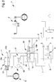
- reference numeral 1 globally indicates a braking device for trailers of agricultural machines.
- the device 1 connectable to the trailer of an agricultural machine or other operating machine, comprises a first and a second female coupling, schematized in the figures by the reference numbers 2 and 3, associable with a trailer and adapted to receive related male couplings, schematized in the figures by the reference numbers 4 and 5, associable with a towing vehicle and adapted to send a pressurized fluid inside the respective female couplings.
- the device 1 then comprises at least one control line 6 communicating with the first female coupling 2 and connectable to the braking system F of the trailer, at least one additional line 7 communicating with the second female coupling 3 and connectable to the automatic and/or parking brake G of the trailer.
- the device 1 also comprises at least one auxiliary line 8 connectable to the additional line 7 following the detachment of the second female coupling 3 from its male coupling 5.
- first valve means 9 are adapted to isolate and place in communication the additional line 7 with the auxiliary line 8 following the coupling and the uncoupling, respectively, of the second female coupling 3 from its male coupling 5.
- the auxiliary line 8 is connected to the control line 6 by means of second one-way valve means 10 adapted to allow only the outflow of the working fluid from the auxiliary line 8 to the control line 6 following a pressure difference between them.
- the device 1 comprises, therefore, also a command device 11 of the automatic and/or parking brake G.
- the command device 11 comprises first elastic means 12 adapted to activate the automatic and/or parking brake G and at least one fluid-operated cylinder 13 adapted to interact with the first elastic means themselves.
- the first elastic means 12 are adapted to actuate the command of the automatic and/or parking brake G for the activation of the same.
- the cylinder 13 in turn comprises a body 13a inside which is housed in a sliding manner one rod 13b, which interacts with the first elastic means 12 and on which at least a first chamber 14 operates in contrast to the action of first elastic means 12 to cause the release of the automatic and/or parking brake G.
- the cylinder 13 also comprises a second chamber 15, which operates on the rod 13b on the opposite side of the first chamber 14, or in the same direction as the action of the first elastic means 12.
- the cylinder 13 is of the double-acting type and the operational surfaces of the rod 13b facing the chambers 14 and 15 are substantially equal to each other.
- the cylinder 13 is connected in a fluid-operated manner to the service braking system F of the trailer.
- the automatic and/or parking brake G also performs the service brake function.
- the rod 13b comprises a first and a second portion, respectively identified with the reference numbers 13b' and 13b", movable reciprocally between them.
- the first portion 13b' is adapted to interact with the first elastic means 12 depending on the pressure present in the chambers 14, 15, and a second portion 13b" is adapted to interact with the automatic and/or parking brake G to command the activation/deactivation thereof and activate also the service braking.
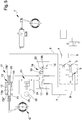
- a third chamber 22 communicating with the control line 6 and adapted to move the second portion 13b" to command the activation of the automatic and/or parking brake G (which, as mentioned above, operates in this embodiment also as a service brake) following the increase in pressure along said control line 6.
- the third chamber 22 is placed in communication with the control line 6 through a canal 23 formed in the first portion 13b'. It follows, therefore, that in this second embodiment, the automatic and/or parking brake G, which also operates as a service brake, is activated following the increase in pressure along the control line 6 irrespective of the pressure present in the chambers 14 and 15.
- a valve 16 which has a spool 17 movable between a normal operation configuration, in which it places the first chamber 14 in communication with the additional line 7 and the second chamber 15 with a lower pressure line so as to allow draining the working fluid contained in it and permit the deactivation of the automatic and/or parking brake G, and a braking configuration, in which it places the first and the second chamber 14, 15 in communication between them, so as to make ineffective the action of the rod 13b (which is therefore floating) on the first elastic means 12 which by expanding activate the automatic and/or parking brake G.
- the second chamber 15 in the normal operation configuration, is placed in communication with the auxiliary line 8, so that the working fluid contained therein drains along the control line 6, via the second valve means 10, when this is at a lower pressure, while in the braking configuration, both chambers 14, 15 are placed in communication with the auxiliary line 8.
- valve 16 comprises a body 18 which defines a seat 19 inside which the spool 17 is housed in a sliding manner.
- the seat 19 has four openings communicating with the additional line 7, with the auxiliary line 8, with the first chamber 14 and with the second chamber 15, respectively.
- spool 17 On the spool 17 operate two compartments, opposite to one another, for example defined inside the seat 19 between the ending parts of the spool itself and the body 18, of which a first compartment 19a placed in communication with the additional line 7 and adapted to push the spool 17 towards the normal operation configuration and a second compartment 19b, inside which are housed second elastic means 20, operating in a direction opposite to the first compartment 19a.
- the second compartment 19b is placed in communication with the auxiliary line 8, to drain and receive the working fluid, which operates therefore on the spool 17 in the same direction as the action exerted by the second elastic means 20.
- the spool 17 is therefore adapted to move towards the normal operation configuration following the connection of the female couplings 2, 3 to the corresponding male couplings 4, 5 and the pressurization of the additional line 7 and to move towards the braking configuration following the uncoupling between them, in such case the connection occurring between the additional line 7 and the auxiliary line 8 by means of the first valve means 9 and, therefore, the connection between the compartments 19a and 19b.
- the spool 17 is adapted to substantially move the same volume of working fluid in both directions.
- the device 1 comprises pumping means 21 interposed between the command device 11 and the valve 16, which are manually operable to supply the first chamber 14 of the cylinder 13 so as to release the automatic and/or parking brake G even when the trailer is detached from the towing vehicle.
- the pumping means 21 are of the double acting type, while in the embodiments of Figures 4 and 5 , the pumping means 21 are of the single acting type.
- a supply/drain channel 25 interposed between the valve 16 and the command device 11 and arranged in parallel to the pumping means 21.
- the supply/drain channel 25 allows the inflow and outflow of the working fluid from the first chamber 14 towards the valve 16 following the attachment and the detachment, respectively, of the trailer from the towing vehicle and, therefore, the connection between the additional line 7 and the auxiliary line 8.
- a valve device 26 manually operable to move it from an open configuration, in which it allows the passage of the working fluid, to a closed configuration, in which it prevents the passage of the working fluid.
- valve device 26 is brought to the closed configuration when the second female coupling 3 is separated from its male coupling 5 and there is the need to pressurize the first chamber 14 to compress the first elastic means 12 and thus release the automatic and/or parking brake G.
- the valve device 26 By bringing the valve device 26 to the closed configuration it is in fact possible to supply the first chamber 14 by means of the pumping means 21.
- the valve device 26 comprises opening means, e.g. of the spring type, (not visible in detail in the figures) operatively connected to the additional line 7 and adapted to return the valve device itself from the closed configuration to the open configuration upon reaching a predefined pressure of the working fluid along the additional line 7.
- opening means e.g. of the spring type, (not visible in detail in the figures) operatively connected to the additional line 7 and adapted to return the valve device itself from the closed configuration to the open configuration upon reaching a predefined pressure of the working fluid along the additional line 7.
- valve device 26 can be operable automatically following the accidental detachment of the trailer from the towing vehicle, or following the detachment of the female couplings 2, 3 from the relative male couplings 4, 5.
- the operation of the present invention is as follows.
- the additional line 7 receives the working fluid under pressure, between 15 bar and 35 bar, and the first valve means 9 isolate the additional line itself from the auxiliary line 8.
- the working fluid coming from the additional line 7 enters therefore the first chamber 14 of the cylinder 13 so as to cause it to move in contrast to the first elastic means 12.
- the compression of the first elastic means 12 causes the deactivation of the automatic and/or parking brake G.
- the working fluid in the second chamber 15 of the cylinder 13 and in the second compartment 19b flows out through the auxiliary line 8 and drains, via the second valve means 10, on the control line 6 following a pressure difference between the two lines. This pressure difference occurs at least when the pressure of the working fluid that supplies the service braking system F drops to zero.
- the first valve means 9 change their state by placing the additional line 7 in mutual communication with the auxiliary line 8.
- the automatic and/or parking brake G is activated following the pressurization of the control line 6, thus operating also as a service brake.
- the pressurized working fluid present along the control line 6 enters the third chamber 22 by exerting a force on the second portion 13b" so as to push it away from the first portion 13b' and actuate the automatic and/or parking brake G.
- Figure 5 shows the operation configuration in which the automatic and/or parking brake G which, as discussed above, also performs the function of service brake, is activated due to the effect of the pressure present along the control line 6 despite the valve 16 is in the normal operation configuration and the first elastic means are, therefore, compressed.
- the described invention achieves the intended objects and in particular the fact is underlined that the braking device making the subject of the present invention allows the use of automatic and/or parking brakes with springs on any trailer, and irrespectively of the type of dual-line braking system of its towing vehicle.
Landscapes
- Engineering & Computer Science (AREA)
- Transportation (AREA)
- Mechanical Engineering (AREA)
- Braking Systems And Boosters (AREA)
- Regulating Braking Force (AREA)
- Sowing (AREA)
- Soil Working Implements (AREA)
- Control Of Driving Devices And Active Controlling Of Vehicle (AREA)
Claims (14)
- Bremsvorrichtung (1) für Anhänger von landwirtschaftlichen Maschinen, umfassend:- eine erste und eine zweite Kupplungsbuchse (2, 3), die einem Anhänger zuordenbar und in der Lage sind, entsprechende Kupplungsstecker (4, 5) aufzunehmen, die einem Zugfahrzeug zuordenbar sind, um ein druckbeaufschlagtes Fluid in jeweilige Kupplungsbuchsen (2, 3) zu senden;- mindestens eine Steuerleitung (6), die mit der ersten Kupplungsbuchse (2) in Verbindung steht und mit dem Betriebsbremssystem (F) des Anhängers verbindbar ist, mindestens eine zusätzliche Leitung (7), die mit der zweiten Kupplungsbuchse (3) in Verbindung steht und mit der automatischen Bremse und/oder Feststellbremse (G) des Anhängers verbindbar ist;- eine Steuerungsvorrichtung (11) der automatischen Bremse und/oder Feststellbremse (G) des Anhängers, umfassend erste elastische Mittel (12), die in der Lage sind, die automatische Bremse und/oder Feststellbremse selbst zu aktivieren, und mindestens einen fluidbetriebenen Zylinder (13), der in der Lage ist, mit den ersten elastischen Mitteln selbst zu interagieren; wobei der fluidbetriebene Zylinder (13) mindestens eine erste Kammer (14) aufweist, die in der Lage ist, die entsprechende Stange (13b) in der entgegengesetzten Richtung zur Wirkung der ersten elastischen Mittel (12) zu bewegen;dadurch gekennzeichnet, dass der Zylinder (13) mindestens eine zweite Kammer (15) aufweist, die auf der gegenüberliegenden Seite der ersten Kammer (14) wirkt und in der Lage ist, die entsprechende Stange (13b) in der gleichen Richtung wie die Wirkung der ersten elastischen Mittel (12) zu bewegen;
und dadurch, dass es umfasst
mindestens ein Ventil (16), das zwischen den Kupplungsbuchsen (2, 3) und der Steuerungsvorrichtung (11) zwischengeschaltet ist und eine Spule (17) aufweist, die beweglich ist zwischen einer Bremskonfiguration, in der die erste und die zweite Kammer (14, 15) wechselseitig in Verbindung gebracht sind, wodurch sich die ersten elastischen Mittel (12) frei ausdehnen können, und eine Normalbetriebskonfiguration, bei der die erste Kammer (14) mit der zusätzlichen Leitung (7) in Verbindung gebracht ist und die zweite Kammer (15) mit einer Niederdruckleitung verbindbar ist, um die ersten elastischen Mittel (12) zum Lösen der automatischen Bremse und/oder Feststellbremse (G) zusammenzudrücken. - Vorrichtung (1) nach Anspruch 1, dadurch gekennzeichnet, dass auf die Spule (17) von gegenüberliegenden Seiten ein erster Raum (19a), der mit der zusätzlichen Leitung (7) in Verbindung steht und in der Lage ist, sie in Richtung der Normalbetriebskonfiguration zu schieben, und ein zweiter Raum (19b), in dem zweite elastische Mittel (20) untergebracht sind, wirken.
- Vorrichtung (1) nach Anspruch 1 oder 2, dadurch gekennzeichnet, dass sie mindestens eine Hilfsleitung (8) umfasst, die mit der zusätzlichen Leitung (7) auf das Lösen der zweiten Kupplungsbuchse (3) von dem entsprechenden Kupplungsstecker (5) folgend verbindbar ist, wobei die erste und zweite Kammer (14, 15) in der Bremskonfiguration mit der Hilfsleitung (8) mit dem Ventil (16) in Verbindung stehen und in der Normalbetriebskonfiguration mit der zusätzlichen Leitung (7) bzw. mit der Hilfsleitung (8) mit dem Ventil (16) in Verbindung stehen.
- Vorrichtung (1) nach Anspruch 3, dadurch gekennzeichnet, dass die Hilfsleitung (8) mit dem zweiten Raum (19b) in Verbindung steht, sich die Spule (17) auf die Verbindung der zweiten Kupplungsbuchse (3) mit dem entsprechenden Kupplungsstecker (5) folgend mit der zusätzlichen Leitung (7) unter Druck in Richtung der Normalbetriebskonfiguration bewegt und auf deren Abkuppeln folgend in Richtung der Bremskonfiguration bewegt, wobei die Hilfsleitung (8) mit der zusätzlichen Leitung (7) in Verbindung steht.
- Vorrichtung (1) nach Anspruch 3 oder 4, dadurch gekennzeichnet, dass sie erste Ventilmittel (9) umfasst, die in der Lage sind, die zusätzliche Leitung (7) bzw. die Hilfsleitung (8) auf das An- und Abkuppeln der zweiten Kupplungsbuchse (3) von dem entsprechenden Kupplungsstecker (5) folgend zu isolieren und in Verbindung zu setzen.
- Vorrichtung (1) nach einem oder mehreren der Ansprüche 2 bis 5, dadurch gekennzeichnet, dass die Hilfsleitung (8) mit der Steuerleitung (6) über ein zweites Einwegventil (10) verbunden ist.
- Vorrichtung (1) nach einem oder mehreren der vorstehenden Ansprüche, dadurch gekennzeichnet, dass der fluidbetriebene Zylinder (13) vom doppeltwirkenden Typ ist und dass die den Kammern (14, 15) zugewandten Betriebsflächen der Stange (13b) im Wesentlichen gleich sind.
- Vorrichtung (1) nach einem oder mehreren der vorstehenden Ansprüche, dadurch gekennzeichnet, dass sie Pumpmittel (21) umfasst, die zwischen der Steuerungsvorrichtung (11) und dem Ventil (16) zwischengeschaltet und manuell betreibbar sind, um die erste Kammer (14) des fluidbetriebenen Zylinders (13) zu versorgen, und dass sie mindestens einen Zu-/Ableitungskanal (25) umfasst, der zwischen dem Ventil (16) und der Steuerungsvorrichtung (11) zwischengeschaltet und parallel zu den Pumpmitteln (21) angeordnet ist.
- Vorrichtung (1) nach Anspruch 8, dadurch gekennzeichnet, dass die Pumpmittel (21) vom doppeltwirkenden Typ sind.
- Vorrichtung (1) nach Anspruch 8 oder 9, dadurch gekennzeichnet, dass sie mindestens eine Ventilvorrichtung (26) umfasst, die entlang des Zu-/Ableitungskanals (25) angeordnet und manuell bedienbar ist, um sie von einer offenen Konfiguration in eine geschlossene Konfiguration zu bewegen.
- Vorrichtung (1) nach Anspruch 10, dadurch gekennzeichnet, dass die Ventilvorrichtung (26) Öffnungsmittel umfasst, die wirksam mit der zusätzlichen Leitung (7) verbunden sind und in der Lage sind, die Ventilvorrichtung selbst aus der geschlossenen Konfiguration in die offene Konfiguration zurückzubringen, wenn ein vordefinierter Druck des Arbeitsfluids entlang der zusätzlichen Leitung (7) erreicht ist.
- Vorrichtung (1) nach Anspruch 10 oder 11, dadurch gekennzeichnet, dass die Ventilvorrichtung (26) als Folge des versehentlichen Lösens der Kupplungsbuchsen (2, 3) von den jeweiligen Kupplungssteckern (4, 5) betreibbar ist.
- Vorrichtung (1) nach einem oder mehreren der vorstehenden Ansprüche, dadurch gekennzeichnet, dass der Zylinder (13) in fluidbetriebener Weise mit der Betriebsbremsanlage (F) des Anhängers verbunden ist.
- Vorrichtung (1) nach Anspruch 13, dadurch gekennzeichnet, dass die Stange (13b) einen ersten Abschnitt (13b'), der mit den ersten elastischen Mitteln (12) wechselwirkt, und einen zweiten Abschnitt (13b"), der mit der automatischen Bremse und/oder Feststellbremse (G) wechselwirkt und in Bezug auf den ersten Abschnitt selbst beweglich ist, umfasst; zwischen dem ersten und dem zweiten Abschnitt (13b', 13b") eine dritte Kammer (22) definiert ist, die mit der Steuerleitung (6) verbunden ist und in der Lage ist, den zweiten Abschnitt (13b") zu bewegen, um die Aktivierung der automatischen Bremse und/oder Feststellbremse (G) auf den Druckanstieg entlang der Steuerleitung (6) folgend zu steuern.
Applications Claiming Priority (2)
| Application Number | Priority Date | Filing Date | Title |
|---|---|---|---|
| ITUB2015A005308A ITUB20155308A1 (it) | 2015-10-30 | 2015-10-30 | Dispositivo di frenatura per rimorchi di macchine agricole |
| PCT/IB2016/056434 WO2017072672A1 (en) | 2015-10-30 | 2016-10-26 | Braking device for trailers of agricultural machines |
Publications (2)
| Publication Number | Publication Date |
|---|---|
| EP3368385A1 EP3368385A1 (de) | 2018-09-05 |
| EP3368385B1 true EP3368385B1 (de) | 2019-08-28 |
Family
ID=55410080
Family Applications (1)
| Application Number | Title | Priority Date | Filing Date |
|---|---|---|---|
| EP16809169.2A Active EP3368385B1 (de) | 2015-10-30 | 2016-10-26 | Bremsvorrichtung für anhänger von landwirtschaftlichen maschinen |
Country Status (3)
| Country | Link |
|---|---|
| EP (1) | EP3368385B1 (de) |
| IT (1) | ITUB20155308A1 (de) |
| WO (1) | WO2017072672A1 (de) |
Families Citing this family (2)
| Publication number | Priority date | Publication date | Assignee | Title |
|---|---|---|---|---|
| IT201700052010A1 (it) * | 2017-05-12 | 2018-11-12 | Safim S P A | Dispositivo di controllo di una valvola freno-rimorchio, collegabile all’impianto di frenatura di un rimorchio, per veicoli di traino con trasmissione idrostatica provvista di almeno una pompa a cilindrata variabile |
| IT201800010083A1 (it) * | 2018-11-06 | 2020-05-06 | Safim S P A | Dispositivo per il controllo della frenatura di un rimorchio |
Family Cites Families (2)
| Publication number | Priority date | Publication date | Assignee | Title |
|---|---|---|---|---|
| DE102007047691A1 (de) * | 2007-10-05 | 2009-04-09 | Wabco Gmbh | Elektropneumatischer Feststellbremsmodulator zur Steuerung einer Feststellbremsfunktion von Bremsen eines Anhängefahrzeugs in einem Fahrzeugzug |
| GB2492124B (en) * | 2011-06-22 | 2017-08-09 | Haldex Brake Prod Ab | Vehicle braking system |
-
2015
- 2015-10-30 IT ITUB2015A005308A patent/ITUB20155308A1/it unknown
-
2016
- 2016-10-26 EP EP16809169.2A patent/EP3368385B1/de active Active
- 2016-10-26 WO PCT/IB2016/056434 patent/WO2017072672A1/en active Application Filing
Non-Patent Citations (1)
| Title |
|---|
| None * |
Also Published As
| Publication number | Publication date |
|---|---|
| EP3368385A1 (de) | 2018-09-05 |
| WO2017072672A1 (en) | 2017-05-04 |
| ITUB20155308A1 (it) | 2017-04-30 |
Similar Documents
| Publication | Publication Date | Title |
|---|---|---|
| CN108082158B (zh) | 车辆选挡、停车制动联合控制系统 | |
| EP2426021B1 (de) | Parkventil für einen Nutzfahrzeug-Anhänger | |
| EP3368385B1 (de) | Bremsvorrichtung für anhänger von landwirtschaftlichen maschinen | |
| AU2016401332A1 (en) | Vehicle coupling lines storage and control arrangement | |
| US3650570A (en) | Hydraulically actuated braking system for unitary control of driven and towed vehicles | |
| US3944286A (en) | Brake system including means for ensuring parking brake release | |
| EP3225473B1 (de) | Vorrichtung zur anhängerbremssteuerung | |
| EP2952398B1 (de) | Ventilvorrichtung | |
| PL71949B1 (en) | Relay valve arrangement for a two-circuit pneumatic breaking system of a twin vehicle[su682114a3] | |
| EP3000631B1 (de) | Verbindungssystem für zugfahrzeug-anhänger | |
| EP3650293B1 (de) | Vorrichtung zur steuerung der bremsung eines anhängers | |
| US2814363A (en) | Safety hitch for trailers | |
| EP3000672B1 (de) | Anhängerventilanordnung | |
| EP3319848B1 (de) | Betätigungsvorrichtung eines ventils zum bremsen eines anhängers | |
| EP3085589B1 (de) | Ventilanordnung | |
| EP4054907B1 (de) | Gerät zum steuern der bremsung eines anhängers | |
| EP3064408B1 (de) | Anhängerbremssteuergerät | |
| EP3711982B1 (de) | Pneumatisches gerät zum verbinden eines schleppfahrzeugs mit einem anhänger | |
| US3910641A (en) | Brake system for an articulated carrier | |
| EP3165385B1 (de) | Vorrichtung für eine verbindung zwischen fahrzeug und anhänger | |
| EP2955073B1 (de) | Anordnung zur Verbindung Zugfahrzeug-Anhängerfahrzeug | |
| US3447835A (en) | Vehicle brake system and valve | |
| US2986153A (en) | Control valve for pneumatic braking systems | |
| GB2114245A (en) | A pneumatic braking system for trailers | |
| EP3231677B1 (de) | Bremssteuervorrichtung für kraftfahrzeug |
Legal Events
| Date | Code | Title | Description |
|---|---|---|---|
| STAA | Information on the status of an ep patent application or granted ep patent |
Free format text: STATUS: UNKNOWN |
|
| STAA | Information on the status of an ep patent application or granted ep patent |
Free format text: STATUS: THE INTERNATIONAL PUBLICATION HAS BEEN MADE |
|
| PUAI | Public reference made under article 153(3) epc to a published international application that has entered the european phase |
Free format text: ORIGINAL CODE: 0009012 |
|
| STAA | Information on the status of an ep patent application or granted ep patent |
Free format text: STATUS: REQUEST FOR EXAMINATION WAS MADE |
|
| 17P | Request for examination filed |
Effective date: 20180529 |
|
| AK | Designated contracting states |
Kind code of ref document: A1 Designated state(s): AL AT BE BG CH CY CZ DE DK EE ES FI FR GB GR HR HU IE IS IT LI LT LU LV MC MK MT NL NO PL PT RO RS SE SI SK SM TR |
|
| AX | Request for extension of the european patent |
Extension state: BA ME |
|
| DAV | Request for validation of the european patent (deleted) | ||
| DAX | Request for extension of the european patent (deleted) | ||
| GRAP | Despatch of communication of intention to grant a patent |
Free format text: ORIGINAL CODE: EPIDOSNIGR1 |
|
| STAA | Information on the status of an ep patent application or granted ep patent |
Free format text: STATUS: GRANT OF PATENT IS INTENDED |
|
| INTG | Intention to grant announced |
Effective date: 20190321 |
|
| GRAS | Grant fee paid |
Free format text: ORIGINAL CODE: EPIDOSNIGR3 |
|
| GRAA | (expected) grant |
Free format text: ORIGINAL CODE: 0009210 |
|
| STAA | Information on the status of an ep patent application or granted ep patent |
Free format text: STATUS: THE PATENT HAS BEEN GRANTED |
|
| AK | Designated contracting states |
Kind code of ref document: B1 Designated state(s): AL AT BE BG CH CY CZ DE DK EE ES FI FR GB GR HR HU IE IS IT LI LT LU LV MC MK MT NL NO PL PT RO RS SE SI SK SM TR |
|
| REG | Reference to a national code |
Ref country code: GB Ref legal event code: FG4D |
|
| RIN1 | Information on inventor provided before grant (corrected) |
Inventor name: MAMEI, ENRICO Inventor name: MAMEI, ANDREA Inventor name: MAMEI, ERONNE |
|
| REG | Reference to a national code |
Ref country code: CH Ref legal event code: EP |
|
| REG | Reference to a national code |
Ref country code: AT Ref legal event code: REF Ref document number: 1172015 Country of ref document: AT Kind code of ref document: T Effective date: 20190915 |
|
| REG | Reference to a national code |
Ref country code: IE Ref legal event code: FG4D |
|
| REG | Reference to a national code |
Ref country code: DE Ref legal event code: R096 Ref document number: 602016019639 Country of ref document: DE |
|
| REG | Reference to a national code |
Ref country code: NL Ref legal event code: MP Effective date: 20190828 |
|
| REG | Reference to a national code |
Ref country code: LT Ref legal event code: MG4D |
|
| PG25 | Lapsed in a contracting state [announced via postgrant information from national office to epo] |
Ref country code: BG Free format text: LAPSE BECAUSE OF FAILURE TO SUBMIT A TRANSLATION OF THE DESCRIPTION OR TO PAY THE FEE WITHIN THE PRESCRIBED TIME-LIMIT Effective date: 20191128 Ref country code: SE Free format text: LAPSE BECAUSE OF FAILURE TO SUBMIT A TRANSLATION OF THE DESCRIPTION OR TO PAY THE FEE WITHIN THE PRESCRIBED TIME-LIMIT Effective date: 20190828 Ref country code: NL Free format text: LAPSE BECAUSE OF FAILURE TO SUBMIT A TRANSLATION OF THE DESCRIPTION OR TO PAY THE FEE WITHIN THE PRESCRIBED TIME-LIMIT Effective date: 20190828 Ref country code: LT Free format text: LAPSE BECAUSE OF FAILURE TO SUBMIT A TRANSLATION OF THE DESCRIPTION OR TO PAY THE FEE WITHIN THE PRESCRIBED TIME-LIMIT Effective date: 20190828 Ref country code: HR Free format text: LAPSE BECAUSE OF FAILURE TO SUBMIT A TRANSLATION OF THE DESCRIPTION OR TO PAY THE FEE WITHIN THE PRESCRIBED TIME-LIMIT Effective date: 20190828 Ref country code: FI Free format text: LAPSE BECAUSE OF FAILURE TO SUBMIT A TRANSLATION OF THE DESCRIPTION OR TO PAY THE FEE WITHIN THE PRESCRIBED TIME-LIMIT Effective date: 20190828 Ref country code: PT Free format text: LAPSE BECAUSE OF FAILURE TO SUBMIT A TRANSLATION OF THE DESCRIPTION OR TO PAY THE FEE WITHIN THE PRESCRIBED TIME-LIMIT Effective date: 20191230 Ref country code: NO Free format text: LAPSE BECAUSE OF FAILURE TO SUBMIT A TRANSLATION OF THE DESCRIPTION OR TO PAY THE FEE WITHIN THE PRESCRIBED TIME-LIMIT Effective date: 20191128 |
|
| PG25 | Lapsed in a contracting state [announced via postgrant information from national office to epo] |
Ref country code: ES Free format text: LAPSE BECAUSE OF FAILURE TO SUBMIT A TRANSLATION OF THE DESCRIPTION OR TO PAY THE FEE WITHIN THE PRESCRIBED TIME-LIMIT Effective date: 20190828 Ref country code: GR Free format text: LAPSE BECAUSE OF FAILURE TO SUBMIT A TRANSLATION OF THE DESCRIPTION OR TO PAY THE FEE WITHIN THE PRESCRIBED TIME-LIMIT Effective date: 20191129 Ref country code: IS Free format text: LAPSE BECAUSE OF FAILURE TO SUBMIT A TRANSLATION OF THE DESCRIPTION OR TO PAY THE FEE WITHIN THE PRESCRIBED TIME-LIMIT Effective date: 20191228 Ref country code: RS Free format text: LAPSE BECAUSE OF FAILURE TO SUBMIT A TRANSLATION OF THE DESCRIPTION OR TO PAY THE FEE WITHIN THE PRESCRIBED TIME-LIMIT Effective date: 20190828 Ref country code: LV Free format text: LAPSE BECAUSE OF FAILURE TO SUBMIT A TRANSLATION OF THE DESCRIPTION OR TO PAY THE FEE WITHIN THE PRESCRIBED TIME-LIMIT Effective date: 20190828 Ref country code: AL Free format text: LAPSE BECAUSE OF FAILURE TO SUBMIT A TRANSLATION OF THE DESCRIPTION OR TO PAY THE FEE WITHIN THE PRESCRIBED TIME-LIMIT Effective date: 20190828 |
|
| REG | Reference to a national code |
Ref country code: AT Ref legal event code: MK05 Ref document number: 1172015 Country of ref document: AT Kind code of ref document: T Effective date: 20190828 |
|
| PG25 | Lapsed in a contracting state [announced via postgrant information from national office to epo] |
Ref country code: TR Free format text: LAPSE BECAUSE OF FAILURE TO SUBMIT A TRANSLATION OF THE DESCRIPTION OR TO PAY THE FEE WITHIN THE PRESCRIBED TIME-LIMIT Effective date: 20190828 |
|
| PG25 | Lapsed in a contracting state [announced via postgrant information from national office to epo] |
Ref country code: RO Free format text: LAPSE BECAUSE OF FAILURE TO SUBMIT A TRANSLATION OF THE DESCRIPTION OR TO PAY THE FEE WITHIN THE PRESCRIBED TIME-LIMIT Effective date: 20190828 Ref country code: AT Free format text: LAPSE BECAUSE OF FAILURE TO SUBMIT A TRANSLATION OF THE DESCRIPTION OR TO PAY THE FEE WITHIN THE PRESCRIBED TIME-LIMIT Effective date: 20190828 Ref country code: EE Free format text: LAPSE BECAUSE OF FAILURE TO SUBMIT A TRANSLATION OF THE DESCRIPTION OR TO PAY THE FEE WITHIN THE PRESCRIBED TIME-LIMIT Effective date: 20190828 Ref country code: PL Free format text: LAPSE BECAUSE OF FAILURE TO SUBMIT A TRANSLATION OF THE DESCRIPTION OR TO PAY THE FEE WITHIN THE PRESCRIBED TIME-LIMIT Effective date: 20190828 Ref country code: DK Free format text: LAPSE BECAUSE OF FAILURE TO SUBMIT A TRANSLATION OF THE DESCRIPTION OR TO PAY THE FEE WITHIN THE PRESCRIBED TIME-LIMIT Effective date: 20190828 |
|
| REG | Reference to a national code |
Ref country code: DE Ref legal event code: R119 Ref document number: 602016019639 Country of ref document: DE |
|
| PG25 | Lapsed in a contracting state [announced via postgrant information from national office to epo] |
Ref country code: MC Free format text: LAPSE BECAUSE OF FAILURE TO SUBMIT A TRANSLATION OF THE DESCRIPTION OR TO PAY THE FEE WITHIN THE PRESCRIBED TIME-LIMIT Effective date: 20190828 Ref country code: IS Free format text: LAPSE BECAUSE OF FAILURE TO SUBMIT A TRANSLATION OF THE DESCRIPTION OR TO PAY THE FEE WITHIN THE PRESCRIBED TIME-LIMIT Effective date: 20200224 Ref country code: SK Free format text: LAPSE BECAUSE OF FAILURE TO SUBMIT A TRANSLATION OF THE DESCRIPTION OR TO PAY THE FEE WITHIN THE PRESCRIBED TIME-LIMIT Effective date: 20190828 Ref country code: SM Free format text: LAPSE BECAUSE OF FAILURE TO SUBMIT A TRANSLATION OF THE DESCRIPTION OR TO PAY THE FEE WITHIN THE PRESCRIBED TIME-LIMIT Effective date: 20190828 Ref country code: CZ Free format text: LAPSE BECAUSE OF FAILURE TO SUBMIT A TRANSLATION OF THE DESCRIPTION OR TO PAY THE FEE WITHIN THE PRESCRIBED TIME-LIMIT Effective date: 20190828 |
|
| REG | Reference to a national code |
Ref country code: CH Ref legal event code: PL |
|
| PLBE | No opposition filed within time limit |
Free format text: ORIGINAL CODE: 0009261 |
|
| STAA | Information on the status of an ep patent application or granted ep patent |
Free format text: STATUS: NO OPPOSITION FILED WITHIN TIME LIMIT |
|
| PG2D | Information on lapse in contracting state deleted |
Ref country code: IS |
|
| PG25 | Lapsed in a contracting state [announced via postgrant information from national office to epo] |
Ref country code: LU Free format text: LAPSE BECAUSE OF NON-PAYMENT OF DUE FEES Effective date: 20191026 Ref country code: CH Free format text: LAPSE BECAUSE OF NON-PAYMENT OF DUE FEES Effective date: 20191031 Ref country code: LI Free format text: LAPSE BECAUSE OF NON-PAYMENT OF DUE FEES Effective date: 20191031 Ref country code: DE Free format text: LAPSE BECAUSE OF NON-PAYMENT OF DUE FEES Effective date: 20200501 |
|
| 26N | No opposition filed |
Effective date: 20200603 |
|
| REG | Reference to a national code |
Ref country code: BE Ref legal event code: MM Effective date: 20191031 |
|
| PG25 | Lapsed in a contracting state [announced via postgrant information from national office to epo] |
Ref country code: SI Free format text: LAPSE BECAUSE OF FAILURE TO SUBMIT A TRANSLATION OF THE DESCRIPTION OR TO PAY THE FEE WITHIN THE PRESCRIBED TIME-LIMIT Effective date: 20190828 Ref country code: BE Free format text: LAPSE BECAUSE OF NON-PAYMENT OF DUE FEES Effective date: 20191031 |
|
| PG25 | Lapsed in a contracting state [announced via postgrant information from national office to epo] |
Ref country code: IE Free format text: LAPSE BECAUSE OF NON-PAYMENT OF DUE FEES Effective date: 20191026 |
|
| PG25 | Lapsed in a contracting state [announced via postgrant information from national office to epo] |
Ref country code: CY Free format text: LAPSE BECAUSE OF FAILURE TO SUBMIT A TRANSLATION OF THE DESCRIPTION OR TO PAY THE FEE WITHIN THE PRESCRIBED TIME-LIMIT Effective date: 20190828 |
|
| GBPC | Gb: european patent ceased through non-payment of renewal fee |
Effective date: 20201026 |
|
| PG25 | Lapsed in a contracting state [announced via postgrant information from national office to epo] |
Ref country code: MT Free format text: LAPSE BECAUSE OF FAILURE TO SUBMIT A TRANSLATION OF THE DESCRIPTION OR TO PAY THE FEE WITHIN THE PRESCRIBED TIME-LIMIT Effective date: 20190828 Ref country code: HU Free format text: LAPSE BECAUSE OF FAILURE TO SUBMIT A TRANSLATION OF THE DESCRIPTION OR TO PAY THE FEE WITHIN THE PRESCRIBED TIME-LIMIT; INVALID AB INITIO Effective date: 20161026 |
|
| PG25 | Lapsed in a contracting state [announced via postgrant information from national office to epo] |
Ref country code: GB Free format text: LAPSE BECAUSE OF NON-PAYMENT OF DUE FEES Effective date: 20201026 |
|
| PG25 | Lapsed in a contracting state [announced via postgrant information from national office to epo] |
Ref country code: MK Free format text: LAPSE BECAUSE OF FAILURE TO SUBMIT A TRANSLATION OF THE DESCRIPTION OR TO PAY THE FEE WITHIN THE PRESCRIBED TIME-LIMIT Effective date: 20190828 |
|
| P01 | Opt-out of the competence of the unified patent court (upc) registered |
Effective date: 20230527 |
|
| PGFP | Annual fee paid to national office [announced via postgrant information from national office to epo] |
Ref country code: IT Payment date: 20231024 Year of fee payment: 8 Ref country code: FR Payment date: 20231025 Year of fee payment: 8 |