EP3368164B1 - Fall-prevention device - Google Patents
Fall-prevention device Download PDFInfo
- Publication number
- EP3368164B1 EP3368164B1 EP16809522.2A EP16809522A EP3368164B1 EP 3368164 B1 EP3368164 B1 EP 3368164B1 EP 16809522 A EP16809522 A EP 16809522A EP 3368164 B1 EP3368164 B1 EP 3368164B1
- Authority
- EP
- European Patent Office
- Prior art keywords
- stop
- lever
- fall
- prevention device
- release position
- Prior art date
- Legal status (The legal status is an assumption and is not a legal conclusion. Google has not performed a legal analysis and makes no representation as to the accuracy of the status listed.)
- Active
Links
- 230000003213 activating effect Effects 0.000 claims description 32
- 238000003780 insertion Methods 0.000 claims description 14
- 230000037431 insertion Effects 0.000 claims description 14
- 238000000034 method Methods 0.000 claims description 12
- 230000000452 restraining effect Effects 0.000 claims description 7
- 230000000295 complement effect Effects 0.000 claims description 6
- 230000004913 activation Effects 0.000 description 4
- 230000009471 action Effects 0.000 description 3
- 230000000903 blocking effect Effects 0.000 description 3
- 230000001154 acute effect Effects 0.000 description 2
- 238000006073 displacement reaction Methods 0.000 description 2
- 230000000694 effects Effects 0.000 description 2
- 230000008569 process Effects 0.000 description 2
- 125000006850 spacer group Chemical group 0.000 description 2
- 238000004873 anchoring Methods 0.000 description 1
- 230000008878 coupling Effects 0.000 description 1
- 238000010168 coupling process Methods 0.000 description 1
- 238000005859 coupling reaction Methods 0.000 description 1
- 230000001419 dependent effect Effects 0.000 description 1
- 238000009434 installation Methods 0.000 description 1
- 230000002452 interceptive effect Effects 0.000 description 1
- 230000002093 peripheral effect Effects 0.000 description 1
- 238000012800 visualization Methods 0.000 description 1
Images


Classifications
-
- A—HUMAN NECESSITIES
- A62—LIFE-SAVING; FIRE-FIGHTING
- A62B—DEVICES, APPARATUS OR METHODS FOR LIFE-SAVING
- A62B1/00—Devices for lowering persons from buildings or the like
- A62B1/06—Devices for lowering persons from buildings or the like by making use of rope-lowering devices
- A62B1/14—Devices for lowering persons from buildings or the like by making use of rope-lowering devices with brakes sliding on the rope
-
- A—HUMAN NECESSITIES
- A62—LIFE-SAVING; FIRE-FIGHTING
- A62B—DEVICES, APPARATUS OR METHODS FOR LIFE-SAVING
- A62B35/00—Safety belts or body harnesses; Similar equipment for limiting displacement of the human body, especially in case of sudden changes of motion
- A62B35/0043—Lifelines, lanyards, and anchors therefore
- A62B35/005—Vertical lifelines
Definitions
- the present invention concerns an individual safety device against falls during working at height. More in detail, the present invention concerns a movable fall-prevention device for a securing support and, in particular, flexible and vertical securing supports, such as cables and ropes.
- Fall-prevention devices are known in the art, to which the user can connect by a harness.
- Such fall-prevention devices comprise a restraining groove in which a securing support is held, such as a cable or rope.
- a securing support such as a cable or rope.
- the device In case of fall, the device is prevented from sliding by a lever that, through a locking cam, engages the rope thus locking the sliding thereof inside the device.
- the lever rotates between an open position, in which the cable can be inserted/removed in/to from the device, and a closed position in which the lever, and in particular the locking cam thereof, is engaged with the cable to prevent the sliding thereof as a consequence of the user's fall.
- Known fall-prevention devices such as that described in EP1359980 , further comprise a stop limiting the rotation of the lever in an intermediate position, when moving from the closed position to the open position, thus guaranteeing the device movement along the securing support and, at the same time, preventing the securing support from coming out from the device.
- this kind of fall-prevention devices has a stop for the lever contact and allows the stopping thereof in the intermediate position, the user might inadvertently release the fall-prevention device from the securing support constituting the "lifeline".
- the stop in the intermediate position the stop is in contact with a lever surface not allowing to effectively prevent the stop movement and, therefore, the user can inadvertently move the stop from its operative position, in which the lever rotation is limited.
- the movement of the stop from its operative position allows the lever to move to its open position and then allows the fall-prevention device to be removed from the securing cable or rope.
- the device described in US5265696 is provided with a stop and, in particular, with a locking lever (sleeve lock).
- a locking lever lever lock
- the lever does not allow to prevent effectively the stop from moving and, therefore, the user can inadvertently move the stop from its operative position in which it limits the lever rotation.
- Object of the present invention is to increase the safety level given by known fall-prevention devices.
- object of the present invention to provide a movable fall-prevention device which is particularly safe, reliable and simple to use and implement.
- object of the present invention is to provide a movable fall-prevention device able to be used very safely without possibility for the user, in case of distraction, to inadvertently handle the device so that the latter is unintentionally opened and therefore comes out from the lifeline (securing supporting).
- One of the lever ends comprises a locking cam and the other free end comprises a hole intended to receive a karabiner, or similar connecting elements.
- the device further comprises a stop movable between an operative position, in which it limits the rotation of the lever in an intermediate position, when the lever is moved from the closed position to the open position, and a release position in which it allows the rotation of the lever in the open position.
- the limit can be retracted, i.e. moved from the operative position and therefore not interfere with the lever movement towards its own open position.
- the lever comprises at least one abutment surface cooperating, in the intermediate position, with at least one corresponding engaging surface of the stop to lock the stop to its own operative position (that is to prevent its movement to the release position).
- the abutment surface is tilted by an angle substantially comprised between 90° and 135° with respect to the movement path of the stop (and in particular of its engaging surface) from the operative position towards the release position.
- the angle is measured from the path to the lever anticlockwise.
- the expression "tilted by an angle substantially comprised between 90° and 135°” is herein and in the following used to denote the abutment surface being substantially perpendicular to the stop path (and therefore directed substantially perpendicular to the path), otherwise it is tilted with respect to the perpendicular of an angle up to about 45°.
- the abutment surface is substantially perpendicular to the path or is tilted by an angle substantially up to 45° with respect to the path perpendicular.
- the presence of an abutment surface having the afore said arrangement with respect to the limit movement and in the intermediate position being intended to cooperate, i.e. to intercept a corresponding engaging position of the stop, allows to effectively hamper the stop movement from its operative position to the release position, thus allowing the safety level given by the fall-prevention device to be considerably increased.
- the at least one abutment surface interferes with the stop and hampers the movement thereof to the release position.
- the stop movement is hampered due to the presence of the abutment surface interfering with the stop (by intercepting the path of its movement towards the release position), which constitutes a surface blocking the stop movement to the release position.
- the stop is rotationally movable.
- the arrangement of the abutment surface of the lever with respect to the circular path, and therefore the angular values mentioned before, can be referred to the tangent to the stop movement path.
- the rotation movement of the stop allows its simple activation between the operative position and the release position and the arrangement of the abutment surface substantially perpendicular to the tangent to the path in the intermediate position (or tilted by an angle up to about 45° with respect to the perpendicularity condition) allows to obtain an efficient and safe locking of the stop in its operative position.
- the abutment surface is designed substantially complementary to the engaging surface of the stop.
- substantially complementary is meant that the abutment and engaging surfaces intended to cooperate one with another, have such shape to determine an effective reciprocal engagement and thus avoid undesired sliding effects one to another.
- the lever comprises at least one second abutment surface.
- the lever comprises at least two abutment surfaces, and in particular a first and a second abutment surfaces cooperating with at least two engaging surfaces of the stop.
- the presence of two or more abutment surfaces allows to improve the effectiveness in locking the stop in the operative position and thus to prevent it from moving towards the release position.
- a first abutment surface can be intended to limit the lever rotation in the intermediate position and a second abutment surface is intended to limit the stop rotation towards the release position.
- the at least two abutment surfaces are tilted one to another. More in detail, according to an aspect of the present invention, at least one first abutment surface is arranged in accordance with the afore discussed angular arrangement with respect to the path, and at least one second abutment surface is tilted with respect to the first abutment surface.
- the presence of two or more reciprocally tilted abutment surfaces allows to effectively prevent the stop from moving from its operative position to the release position, thus allowing to considerably increase the safety level the fall-prevention device provides.
- the lever comprises at least two abutment surfaces, for example a first abutment surface and a second abutment surface, which are perpendicular to one another, so that to take a substantially stepped shape.
- the perpendicularity between the two abutment surfaces and in particular the substantially stepped shape allows both to stop the lever rotation towards its open position (by an abutment surface) and to prevent effectively any movement of the stop when the lever is in the intermediate position (by another abutment surface).
- the at least two abutment surfaces are substantially wedge-shaped.
- the two or more surfaces can be tilted by an inner acute angle, and thus to form a wedge intended to cooperate with two or more engaging surfaces of the stop, for example which are arranged to form a seat substantially complementary to the wedge.
- other relative tilts of the first and second abutment surfaces are not excluded from being used, provided that at least one abutment surface is arranged with respect to the stop movement path discussed above.
- the shape of the two or more surfaces herein described referring to the lever can be applied to the two or more engaging surfaces of the stop, and vice versa.
- the engaging surfaces of the stop can be wedge-shaped and the abutment surfaces of the lever can be seat-shaped to accommodate at least part of the wedge.
- the two or more abutment surfaces and/or the two or more engaging surfaces can be blent to one another, for example by a curvature radius or one or more straight line segments.
- the stop comprises an activating arm to drive the movement of the stop from the operative position towards the release position.
- the activating arm is preferably activated manually by the user.
- the activating arm is arranged outside of the device body when the stop is in the operative position thus allowing it to be manually driven, and the body of the device is shaped to house the activating arm for at least part of the movement between the operative position and the release position.
- the activating arm can be activated by the user only for a portion of its movement from the operative position to the release position. It follows that the complete movement of the stop in its release position can be completed by the contact with another device element and preferably by the lever.
- the profile of the activating arm is at the edge of the device body before the release position is reached.
- the activating arm is still housed inside the device body.
- At least part of the lever is contacting the stop, preferably a back surface of the stop, to guide at least part of the movement thereof towards the release position.
- the stop comprises a lower arm, said at least one engaging surface being arranged on said lower arm, preferably at an end thereof.
- the stop comprises a safety arm preventing the insertion/removal of the securing support in/from the passage when said stop is in the operative position and allowing the insertion/removal of the securing support in/from the passage when said stop is in said release position.
- Another aspect of the present invention further relates to a use method of the fall-prevention device and, in particular, to a method for installing/removing the fall-prevention device to the securing support.
- the method according to the invention can be applied to a fall-prevention device comprising a main body having a passage for the insertion/removal of the securing support in/from a restraining groove, wherein the securing support is restrained through a lever rotating between an open position and a closed position.
- One of the lever ends comprises a locking cam and the other free end comprises a hole intended to receive a karabiner, or similar connecting elements.
- the device further comprises a stop movable between an operative position, in which it limits the rotation of the lever in an intermediate position, when the lever is moved from the closed position to the open position, and a release position in which it allows the rotation of the lever in the open position.
- the method provides the step of moving the stop from its operative position towards the release position in order to rotate the lever from the closed position to the open position, thus allowing the insertion/removal of the securing support in/from the groove of the device.
- the user carries out the step of moving (preferably by rotating) the stop towards the release position only partially by directly activating the stop, and particularly an activating arm of the stop.
- the step of moving the stop towards the release position provides for guiding the stop at least for part of the travel by the device lever.
- the activating arm of the stop can be activated by the user only for a portion of its movement from the operative position to the release position. It follows that the complete movement of the stop in its release position can be completed by the contact with another device element and preferably by the lever.
- a step follows wherein the movement of the stop towards the release position is guided by at least part of the lever rotated towards its own open position.
- the lever is contacting the stop, preferably a back surface of the stop, and is rotated to the open position to guide at least part of the movement of the stop towards the release position.
- the step of moving the stop from its operative position towards the release position is carried out before rotating the lever from the closed position to the open position.
- said stop in the step of moving the stop from its operative position towards the release position, said stop is clockwise rotated from the operative position towards said release position.
- said lever in the step of rotating the lever from the closed position towards the open position, said lever is anticlockwise rotated from said closed position towards said open position.
- the user carries out the step of moving, preferably by rotating, the stop towards the release position only partially by directly activating the stop, preferably by acting on an activating arm of the stop.
- the step of moving the stop towards the release position provides for guiding the stop at least for part of the travel by the device lever.
- a step follows wherein the movement of the stop towards the release position is guided by at least part of the lever rotated towards its own open position.
- the method thus allows to increase the safety the device provides, by preventing the user from moving it to the release position only through the stop activation.
- the method needs also the subsequent activation of the lever that guides the stop to the release position.
- the movable fall-prevention device 1 is generally part of individual equipment protecting against high falls and denoted with numeral reference 2 which comprises, in addition to said fall-prevention device 1, a harness 3 comprising at least one anchoring ring 4 with a hooking karabiner 5, or similar connecting elements.
- the fall-prevention device 1 is then intended to be removably connected to a vertical securing support 6 fastened, for example, to a service post 7.
- the movable fall-prevention device 1, hereinafter also referred only as fall-prevention device, in its use position, i.e. connected to the harness 3, can be voluntarily moved upwards HA or downwards BA by normally sliding (i.e. at the user's climb or descent speed) along a cable or rope 6 (preferably substantially vertical), which constitutes the securing support.
- the movable fall-prevention device blocks on the cable 6. It will be understood that the user 8 will be therefore able to climb or descend along a post 7 by leaving the fall-prevention device to slide upwards HA or downwards BA along the safety cable 6, while he/she will be assured against falls since the fall-prevention device 1 is blocked on the cable 6 constituting the securing support.
- the fall-prevention device 1 comprises a main body 1a comprising a passage 40 for the insertion/removal of the securing support 6 in/from a groove or hollow profile 9, preferably straight having axis YY' and intended to receive the securing cable 6.
- a securing cable 6 preferably straight having axis YY' and intended to receive the securing cable 6.
- the securing cable 6 is restrained in the groove 9 by a lever 16 provided with a locking cam 10 designed to engage the cable 6 and prevent the sliding thereof inside the groove, de facto determining the blocking of the fall-prevention device on the cable 6, in case of fall.
- the body 1a of the device comprises a main plate 12a and a secondary plate 12b facing to one another.
- the two plates 12a, 12b can be constrained to one another as known, or be made in one piece.
- the hollow profile 9 is constituted by the wall 11a of the main plate 12a, whose first side edge 13a is bent parallel to said wall, so that to form a preferably semicircular groove 9, whereas the second side edge 14a is in the wall plane and curved.
- the groove preferably has semicircular profile with vertical axis (YY') and substantially has the size of the cable or rope 6 both intended to be housed in its inside.
- the lever 16 comprising the locking cam 10 is constrained to the device 1 so that to be rotationally movable with respect to a transversal axis XX'.
- the lever 16 is preferably rotatable around a pivot constrained to the body 1a of the device.
- the second side edge 14a of the main wall 12a can be shape to be a substantially circular lower ramp having radius R1 centered on the axis XX'.
- the body of the movable fall-prevention device comprises, in addition to the main plate 12a described before and forming the groove 9, a secondary plate 12b.
- the latter is integral with the main body to be parallel thereto and is spaced out of a distance (d) in order to constitute a space (e) between the two plates intended to move the lever 16, in addition to the longitudinal passage 40 for the insertion/removal of the cable 6.
- the secondary plate is configured substantially identical to the wall 11a of the main plate 12a.
- it is constituted by a wall 11b and comprises a first straight side wedge 13b, whereas the second side edge 14b is in the wall plane and curved to constitute a lower ramp.
- the passage 40 is limited laterally by the first edge 13b of the main plate 12a and the first edge 13a of the secondary plate 12b. Obviously, the passage width is larger than the diameter of the cable or rope 6, both intended to be engaged therein. According to a possible embodiment, it has to be noticed that the passage 40 extends parallel to the axis YY' of the groove 9.
- the above mentioned lever 16 is arranged so as to be rotationally movable around the transversal axis XX', preferably at a pivot allowing such rotation. It is arranged so that to move inside the body 1a between the two plates 12a, 12b in the space (e) formed between the main plate 12a and the secondary plate 12b.
- the lever 16 is rotatably assembled around an axis or pivot 21 extending between the two plates so that its hooking end 16" protrudes outside of the ramps 14a, 14b of the two plates 12a, 12b.
- the lever 16 substantially comprises the locking cam 10 substantially at one of the ends (locking end 16') and a hooking hole 23, substantially at the other free end (hooking end 16"), intended to receive a karabiner 5 or similar means connecting to the user and, in particular, to the user's harness.
- the hooking hole 23 is cylindrical and its axis QQ' is arranged at a distance L1 from the axis XX' greater than the value of the radius R1 of the ramp summed to radius of the hole 23, so that its peripheral wall 24 is at a distance L2 from the axis XX' greater than the radius R1.
- the lever 16 comprises a cam 10, for example comprising a locking ramp 25, to guarantee the locking of the fall-prevention device 1 on the securing device 6.
- the lever 16 can then take, by rotation around the XX' axis, two limit positions: an open position as depicted in figures 5 , 6d , 8d , and a closed position as depicted in figures 2 , 6a , 8e .
- the locking cam 10 In the closed position, the locking cam 10 is in contact with the securing cable 10 thus determining the locking thereof due to the friction generated thereon.
- the fall-prevention device 1 comprises two stops 28, 29 to limit the angular displacement of the lever 16, downwards by a lower stop 28, and upwards by an upper stop 29.
- the lower stop 28 can be made through a cylindrical spacer extending between the two plates 12a, 12b in the lower area, whereas the upper stop 29 can be made through another upper cylindrical spacer connecting the upper portion of the two plates 12a, 12b.
- the lever 16 is continuously biased towards its closed position by a spring, preferably a torsion spring 27 (visible in figures 3 and 4 ).
- a spring preferably a torsion spring 27 (visible in figures 3 and 4 ).
- the latter is useful, on the one hand, to keep the fall-prevention device 1 in position on the securing cable 6 when the karabiner 5 is positioned and removed and, on the other hand, it is useful to guarantee the locking of the device 1 in case of fall even before the karabiner 5 secures in turn the lever rotation downwards, i.e. towards its closed position.
- the fall-prevention device 1 comprises a stop 50, preferably a rotationally movable stop, movable between an operative position, in which it limits the rotation of the lever 16 in an intermediate position, when the lever 16 is moved from the closed position to the open position, and a release position in which it allows the rotation of the lever 16 in the open position.
- a stop 50 preferably a rotationally movable stop, movable between an operative position, in which it limits the rotation of the lever 16 in an intermediate position, when the lever 16 is moved from the closed position to the open position, and a release position in which it allows the rotation of the lever 16 in the open position.
- the device 1 comprises a movable and retractable stop 50 for the lever 16, which is intended to limit the rotation of the latter upwards in an intermediate position.
- the stop 50 is constituted by a rotating by a rotating pawl 50.
- the stop 50 is biased in its operative position by the spring 27. It has to be noticed that, although only one spring 27 acting on the limit 50 and the lever 16 is provided for biasing these components respectively in their operative position and closed position, distinct elastic elements can be used to bias the two components independently.
- the stop 50 is intended both to limit the rotation of the lever 16 in an intermediate position and to prevent, due to its shape, the securing support 6 from disengaging inconveniently through the passage 40.
- the stop 50 (or pawl) further comprises a safety arm 51 preventing the insertion/removal of the securing support 6 in/from the passage 40 when the stop 50 is in the operative position and allowing the insertion/removal of the securing support 6 in/from the passage 40 when the stop 50 is in the release position.
- the pawl thanks to its lateral safety arm 51, constitutes an obstacle locking the undesirable disengagement of the securing support 6 through the passage 40.
- the operative position of the stop 50 corresponds to a closed position of the passage 40, whereas the release position of the stop allows the insertion/removal of the securing support 6 in/from the passage 40.
- the pawl constituting a further safety system of the device is biased in its operative and closed stop position by a spring 27, which can advantageously be the same spring biasing the lever 16 in the closed position.
- the stop 50 further comprises an activating arm 55.
- the arm 55 is designed so that to protrude outside of the body 1a of the device when the stop 50 is in the operative position.
- the stop 50 comprises an engaging portion 53 comprising at least one engaging surface 53a, 53b that, as better detailed in the following, is intended to engage the lever 16 and, in particular, an abutment portion 80 of the lever 16 in the intermediate position.
- the abutment portion 80 of the lever 16 comprises at least one abutment surface 80a intended to cooperate, in the intermediate position, with at least one corresponding engaging surface 53a of the stop 50 to lock the stop 50 in its operative position.
- the engaging surface 53 and in particular the at least one engaging surface 53a, is preferably arranged on a lower arm 52 of the stop 50, preferably at one end of the lower arm.
- the pawl (stop) is constituted by three arms, i.e. a lateral safety arm 51 intended to lock the undesirable disengagement of the securing support 6 through the passage 40, a lower arm 52 comprising the engaging portion 53 that engages the lever 16 and is intended to limit the lever rotation in an intermediate position (when the lever is rotated from the operative position towards the closed position), as well as an activating arm 55.
- the pawl (stop) is assembled as rotationally movable around a transversal axis (pivot) 58 arranged between the main plate and the secondary plate in the upper part of the fall-prevention device, substantially in the extension of the first edge 13b of the secondary plate.
- the lateral safety arm 51 goes beyond the edge 13b until it reaches the edge 13a, thereby blocking the passage 40 when the pawl is in the operative position and acting as stop for the lever 16.
- the stop is rotated to the release position, the safety arm 51 clears the passage 40.
- the stop 50 is movable and retractable between an operative position named “safety position", which blocks the passage 40 and limits the lever rotation in its intermediate position, and an idle release position.
- safety position which blocks the passage 40 and limits the lever rotation in its intermediate position
- idle release position an operative position
- the user by simply acting on the stop and in particular on the activating arm 55 to move it from its operative position to the release position and allow the lever 16 to pass from its intermediate position to its open position.
- the body of the device 1a is shaped to house the activating arm for at least part of the movement between the operative position and the release position.
- the activating arm can be activated by the user only for a portion of its movement from the operative position to the release position. It follows that the complete movement of the stop in its release position can be completed only by the contact with the lever 16 at its own back surface 52b.
- the movement driven by the user on the outside of the device of the activating arm can be carried out only until the profile P of the arm 55 is at the side walls 15a, 15b of the device (see figures 6b, 6c and figures 8b, 8c ).
- the activating arm 55 is housed inside the body 1a of the device.
- the stop can be advantageously provided with a roll 56, or similar element to aid the sliding, at its safety arm 51 to guarantee a better guide of the securing support 6 at the upper end of the groove 9.
- the stop 50 limits the rotation of the lever 16 in such position by an abutment portion 80 of the lever cooperating with the engaging portion 53 of the stop 50 that, as mentioned, is preferably arranged at a lower arm 52 of the stop.
- the lever 16 comprises at least one abutment surface 80a for an engaging surface 53a of the stop 50.
- the abutment surface 80a limits the rotation of the stop 50 away from its own operative position towards the release position.
- the presence of the abutment surface 80a allows to prevent the rotation movement of the stop towards the release portion when the intermediate position of the lever 16 has been reached.
- the lever 16 and in particular its abutment portion 80 comprises a first abutment surface 80a and a second abutment surface 80b.
- the first abutment surface 80a is adapted to limit the rotation of the stop 50 away from its own operative position towards the release position.
- the first abutment surface 80a and a second abutment surface 80b are substantially perpendicular to one another.
- the first abutment surface 80a is adapted to limit the rotation of the stop 50 towards the release position
- the second abutment surface 80b is adapted to limit the rotation of the lever 16 in the intermediate position when the latter is rotated from the open position to the closed position.
- the abutment portion 80 of the lever 16 takes a substantially stepped form allowing to effectively avoid any movement of the stop 50 when the lever 16 is in the intermediate position in engagement with the engaging portion 53 of the stop 50.
- the two abutment surfaces 80a, 80b substantially are wedge-shaped and are intended to cooperate with the engaging surfaces 53a, 53b of the stop 50.
- the at least two abutment surfaces 80a, 80b are tilted one to another.
- the abutment surface 80a in the intermediate position of the lever 16, is arranged substantially perpendicular to the movement path T of the stop 50 from the operative position to the release position.
- the abutment surface 80a is tilted by an angle ⁇ substantially equal to 90° with respect to the movement path T of the stop 50.
- the abutment surface 80a provides an effective obstacle for the undesirable movement of the stop 50, for example as a consequence of an unintentional activation of the activating arm 55 by the user.
- substantially perpendicular to the path herein means that the abutment surface 80a is arranged substantially perpendicular to the movement direction, and in particular substantially perpendicular to the tangent T' to the path, or perpendicular to the direction of the velocity vector, the engaging portion 53 of the stop and in particular the engaging portion 53a intended to cooperate with the abutment surface 80a.
- the movement path will be circular.
- substantially perpendicular to the circular path means that the abutment surface 80a is substantially perpendicular to the tangent T' to the path, or to the direction of the velocity vector (tangential velocity) of the engaging surface 53a of the stop.
- the abutment surface 80a can be arranged as tilted by an angle substantially comprised between 90° and 135° with respect to the movement path T of the stop (and in particular of its engaging surface) from the operative position towards the release position.
- the abutment surface 80a can be arranged substantially perpendicular to the path T of the stop (and therefore substantially directed along the perpendicular to the path), as in the embodiment of figures 1-9 , or it is tilted with respect to the perpendicular to the path by an angle up to about 45° (as in the embodiment of figure 10 ). In other words, the abutment surface 80a is substantially perpendicular to the path or is tilted by an angle up to 45° with respect to the path perpendicular.
- the abutment surface 80a in the intermediate position of the lever 16, is arranged as tilted by an angle ⁇ substantially equal to 135° with respect to the movement path T of the stop 50 from the operative position to the release position.
- the abutment surface 80a in the intermediate position of the lever 16, is arranged as tilted by an angle equal to 135° with respect to the tangent of the movement path T of the stop 50 from the operative position to the release position.
- the lever comprises a second abutment surface 80b intended to cooperate with a second engaging surface 53b of the stop 50.
- the first and the second abutment surfaces 80a, 80b are tilted to one another to form an inner acute angle and thus to form a wedge intended to cooperate with two engaging surfaces 53a, 53b of the stop.
- the abutment portion 80 is designed substantially complementary to the engaging surface 53 of the stop 50.
- the abutment portion 80 and the engaging portion 53 both intended to contact one another in the intermediate position can be, for example, both step-shaped and complementary to one another, or can be wedge-shaped and intended to cooperate with a corresponding seat, in order to achieve the effect of efficiently prevent the undesirable movement of the stop towards the release position.
- the engaging portion 53 arranged at the end of the lower arm 52 has a substantially stepped-shape able to couple with the abutment portion 80 also substantially stepped, through the two abutment surfaces 80a,80b substantially perpendicular to one another.
- the abutment portion 80 is arranged on a lateral arm 16a of the lever 16.
- the abutment portion 80 and in particular the at least one abutment surface 80a is arranged at the end of the arm 16a.
- the arm 16a extends laterally from the lever 16, preferably in a portion comprised between the rotation axis of the lever and the hooking hole 23.
- the lateral arm 16a of the lever 16 has a substantially curved shape, preferably substantially circular, that follows the profile of the body 1a of the device at the edges 14a, 14b of the plates.
- the lever 16 comprises a seat 16b designed to accommodate at least part of the stop 50 (as visible in figures 6c and 8c ) and, in particular, the lower arm 52 when the latter is rotated towards the release position.
- the seat 16b is arranged under the lateral arm 16a of the lever 16 and, in particular, between the rotation axis of the lever and the point from which the lateral arm 16a extends from the profile of the lever 16.
- the device 1, during the use, can be in three different possible positions, which will be better detailed in the following.
- the figures 6a , 8a show the open position in which the cable 6 can be inserted/removed in/from the device.
- the lever 16 In such a position, the lever 16 is in its open position and the stop 50 is in the release position.
- the intermediate position of the lever 16 is, for example, visible in figures 7 , 9 and 10 in which the stop 50 is in its own operative position.
- the abutment portion 80 provided with the at least one abutment surface 80a allows to effectively prevent the undesirable movement of the stop away from its own operative position.
- the locking position is, for example, visible in figure 6e in which the lever 16 is in its own closed position with the locking cam 10 in contact with the cable, and the stop 50 is in its own operative position.
- the fall-prevention device 1 is in the open position while the cable is inserted and removed.
- the fall-prevention device when used as connected to the cable, can be used during climb or descent.
- the user rotates the lever 16 upwards (HA) in accordance with R1b (anticlockwise rotation).
- R1b anticlockwise rotation
- the lever 16 reaches the intermediate position, i.e. the portion 80 abuts on the end 53 of the arm 52.
- the lever 16 prevents the cable from releasing the groove 9 and, when the lever 16 is released, the latter rotates again downwards in accordance with (R2), thus causing the fall-prevention device to lock on the cable.
- Figures 6a-e depict the various steps of connecting (assembling) the fall-prevention device according to the present invention to the securing cable.
- a karabiner 5 is advantageously connected to the hole 23 and connects the device to the user's harness, so that the tool is constrained to the user and cannot be lost.
- the user operates, for example by leaning the first plate 12a of the fall-prevention device 1 in the palm of the right hand, the activating arm 55 of the stop downwards according to R1a (clockwise) to disengage the passage 40 for the cable.
- the body 1a of the device 1 is shaped so that the upper surface of the activating arm 55 (and in particular the upper profile (edge) P of the activating arm) is arranged at the upper profile (edge) 15a, 15b of the device body before reaching the release position.
- the lateral arm 16a of the lever 16 is designed so that, in the open position of the lever 16, it contacts the stop and, in particular, the lower arm 52 to move it to the release position, as shown in figure 6d .
- the stop 50 and in particular the safety arm 51 disengages the passage 40 completely, the coupling of the fall-prevention device with the cable 6 is thus possible.
- the user then engages the cable 6 in the groove 9 and releases the lever 16 and the stop 50 that, due to the spring 27, will move to the close position and the operative position, respectively, as depicted in figure 6e .
- the method of connecting the fall-prevention device 1 to the cable therefore comprises the user's action both onto the stop 50 and the lever 16.
- the lever 16 before raising the lever 16 it is necessary to rotate the activating arm 55 of the stop 50 in accordance with (R1a) to move the stop away from its operative position, otherwise the lever, during the movement towards the open position, would reach the intermediate contact position of the abutment portion 80 with the engaging portion 53 of the stop (for example as shown in figure 7 ).
- the lever 16 is biased by the spring 27 and turns downwards in accordance with (R2) until the locking cam 25 tightens the cable 6 by restraining it in the groove 9, while the stop blocks the passage 40 by means of its safety arm 51.
- the fall-prevention device 1 In the position depicted in figures 6e , 8a , the fall-prevention device 1 is locked so that to avoid any undesirable descent downwards (BA) and prevent the user's fall, but it might be moved upwards (HA) up to its intermediate position of engagement with the stop, by the rotation of the lever 16 upwards in accordance with (R1b).
- Figures 8a-e depict the various steps of removing the fall-prevention device according to the present invention from the cable.
- the user rotates the stop 50 in accordance with (R1a) towards the release position, as shown in figure 1b.
- the lever 16 can be rotated in accordance with (R1b), as shown for example in figure 8c , until the abutment portion 80 of the lever 16 engages the back surface 52b (or back) of the arm 52 of the stop 50 and the stop 50 is involved in completing its rotation and then the open position of the lever is reached.
- the movement of the lever 16 to its own open position terminates the movement of the stop to its own release position, as shown in figure 8d .
- the fall-prevention device can be disengaged from the cable 6 and the stop and the lever 16 can be both released, as shown in figure 8e .
- the process of removing the fall-prevention device from the cable according to the present invention is particularly safe thanks to a necessary sequential and consecutive action on the arm 55 of the stop 50 and on the lever 16, to cause the removal of the fall-prevention device.
- the only rotation of the lever 16 is not sufficient to unlock the fall-prevention device.
Description
- The present invention concerns an individual safety device against falls during working at height. More in detail, the present invention concerns a movable fall-prevention device for a securing support and, in particular, flexible and vertical securing supports, such as cables and ropes.
- In the art it is known that the personnel having to intervene on high installations and, for this purpose, to climb or descend on pylons or posts, must be secured against dangerous falls. For example, it is the case of installers or system repairers such as, for example, cableway or chair lift systems and similar. It is therefore necessary to secure these operators so that they can climb and descend freely, with no fall risks. Devices constituted by a vertically arranged securing rope or cable are already known, named "lifeline", to which the user is connected so that to move upwardly and downwardly. For this purpose, he/she is provided with individual protecting equipment connecting him/her to the "lifeline" and comprising a harness fastened to a movable fall-prevention device.
- However, known devices are not completely satisfactory about their use comfort and reliability. In particular, it is possible for the user to inadvertently release the movable fall-prevention device from the "lifeline" during its use.
- Such possibility constitutes a high risk for the user's safety, in particular if the user is inexperienced. Fall-prevention devices are known in the art, to which the user can connect by a harness. Such fall-prevention devices comprise a restraining groove in which a securing support is held, such as a cable or rope. In case of fall, the device is prevented from sliding by a lever that, through a locking cam, engages the rope thus locking the sliding thereof inside the device.
- In particular, the lever rotates between an open position, in which the cable can be inserted/removed in/to from the device, and a closed position in which the lever, and in particular the locking cam thereof, is engaged with the cable to prevent the sliding thereof as a consequence of the user's fall.
- Known fall-prevention devices, such as that described in
EP1359980 , further comprise a stop limiting the rotation of the lever in an intermediate position, when moving from the closed position to the open position, thus guaranteeing the device movement along the securing support and, at the same time, preventing the securing support from coming out from the device. However, also if this kind of fall-prevention devices has a stop for the lever contact and allows the stopping thereof in the intermediate position, the user might inadvertently release the fall-prevention device from the securing support constituting the "lifeline". - Indeed, in the intermediate position of the lever, i.e. when the lever is contacting the stop in its intermediate position, there is the condition of possible removal of the fall-prevention device by forcing the stop rotation.
- This is possible because, by acting on the stop, the user can transmit rotation on the lever in contact with the stop itself. In fact, the contact between the stop and the lever happens at a lever surface tilted with respect to the stop and therefore not preventing effectively the stop rotation.
- In other words, in the intermediate position the stop is in contact with a lever surface not allowing to effectively prevent the stop movement and, therefore, the user can inadvertently move the stop from its operative position, in which the lever rotation is limited. The movement of the stop from its operative position allows the lever to move to its open position and then allows the fall-prevention device to be removed from the securing cable or rope.
- Also the device described in
US5265696 is provided with a stop and, in particular, with a locking lever (sleeve lock). However, also in this device, when the lever is in contact with the stop, the rotation of the stop is not prevented. In fact, also in the device according toUS5265696 , the lever does not allow to prevent effectively the stop from moving and, therefore, the user can inadvertently move the stop from its operative position in which it limits the lever rotation. Object of the present invention is to increase the safety level given by known fall-prevention devices. In particular, object of the present invention to provide a movable fall-prevention device which is particularly safe, reliable and simple to use and implement. - Moreover, object of the present invention is to provide a movable fall-prevention device able to be used very safely without possibility for the user, in case of distraction, to inadvertently handle the device so that the latter is unintentionally opened and therefore comes out from the lifeline (securing supporting).
- These and other objects are achieved by a fall-prevention device according to
claim 1. Further aspects and features of the device are set forth in the dependent claims. - The movable fall-prevention device for a securing support (such as cable or ropes) according to the invention comprises a main body having a passage for the insertion/removal of the securing support in/from a restraining groove, wherein the securing support is restrained through a lever rotating between an open position and a closed position. One of the lever ends comprises a locking cam and the other free end comprises a hole intended to receive a karabiner, or similar connecting elements. The device further comprises a stop movable between an operative position, in which it limits the rotation of the lever in an intermediate position, when the lever is moved from the closed position to the open position, and a release position in which it allows the rotation of the lever in the open position. In other words, according to an aspect of the invention, the limit can be retracted, i.e. moved from the operative position and therefore not interfere with the lever movement towards its own open position.
- According to an aspect of the invention, the lever comprises at least one abutment surface cooperating, in the intermediate position, with at least one corresponding engaging surface of the stop to lock the stop to its own operative position (that is to prevent its movement to the release position).
- The abutment surface is tilted by an angle substantially comprised between 90° and 135° with respect to the movement path of the stop (and in particular of its engaging surface) from the operative position towards the release position. The angle is measured from the path to the lever anticlockwise.
- It has to be noticed that the expression "tilted by an angle substantially comprised between 90° and 135°" is herein and in the following used to denote the abutment surface being substantially perpendicular to the stop path (and therefore directed substantially perpendicular to the path), otherwise it is tilted with respect to the perpendicular of an angle up to about 45°. In other words, the abutment surface is substantially perpendicular to the path or is tilted by an angle substantially up to 45° with respect to the path perpendicular.
- What described above applies both to flat abutment surfaces and/or to flat engaging surfaces and also to curved surfaces. In this case, angular relations discussed above can be defined in relation to the path, by referring to a plane or line lying on the surface, or tangent to the surface.
- Advantageously, the presence of an abutment surface having the afore said arrangement with respect to the limit movement and in the intermediate position being intended to cooperate, i.e. to intercept a corresponding engaging position of the stop, allows to effectively hamper the stop movement from its operative position to the release position, thus allowing the safety level given by the fall-prevention device to be considerably increased. In fact, contrary to what happens in devices known in the art in which the stop movement is not intercepted and thus not hampered (prevented) by the lever, in the device according to the present invention, in the intermediate position the at least one abutment surface interferes with the stop and hampers the movement thereof to the release position. In other words, the stop movement is hampered due to the presence of the abutment surface interfering with the stop (by intercepting the path of its movement towards the release position), which constitutes a surface blocking the stop movement to the release position. According to an aspect of the present invention, the stop is rotationally movable. In this case, it has to be noticed that the arrangement of the abutment surface of the lever with respect to the circular path, and therefore the angular values mentioned before, can be referred to the tangent to the stop movement path.
- Advantageously, the rotation movement of the stop allows its simple activation between the operative position and the release position and the arrangement of the abutment surface substantially perpendicular to the tangent to the path in the intermediate position (or tilted by an angle up to about 45° with respect to the perpendicularity condition) allows to obtain an efficient and safe locking of the stop in its operative position.
- In fact, in the intermediate position, the user cannot inadvertently move the stop from its operative position, just because of the obstacle the abutment surface of the lever provides.
- According to an aspect of the present invention, the abutment surface is designed substantially complementary to the engaging surface of the stop. With the expression "substantially complementary" is meant that the abutment and engaging surfaces intended to cooperate one with another, have such shape to determine an effective reciprocal engagement and thus avoid undesired sliding effects one to another. According to an aspect of the present invention, the lever comprises at least one second abutment surface. In other words, the lever comprises at least two abutment surfaces, and in particular a first and a second abutment surfaces cooperating with at least two engaging surfaces of the stop.
- Advantageously, the presence of two or more abutment surfaces allows to improve the effectiveness in locking the stop in the operative position and thus to prevent it from moving towards the release position.
- According to different possible embodiments, a first abutment surface can be intended to limit the lever rotation in the intermediate position and a second abutment surface is intended to limit the stop rotation towards the release position. According to an aspect of the present invention, the at least two abutment surfaces are tilted one to another. More in detail, according to an aspect of the present invention, at least one first abutment surface is arranged in accordance with the afore discussed angular arrangement with respect to the path, and at least one second abutment surface is tilted with respect to the first abutment surface. Advantageously, the presence of two or more reciprocally tilted abutment surfaces, for example the presence of a first abutment surface and a second abutment surface tilted one to another, allows to effectively prevent the stop from moving from its operative position to the release position, thus allowing to considerably increase the safety level the fall-prevention device provides.
- According to a possible embodiment, the lever comprises at least two abutment surfaces, for example a first abutment surface and a second abutment surface, which are perpendicular to one another, so that to take a substantially stepped shape.
- Advantageously, the perpendicularity between the two abutment surfaces and in particular the substantially stepped shape, allows both to stop the lever rotation towards its open position (by an abutment surface) and to prevent effectively any movement of the stop when the lever is in the intermediate position (by another abutment surface).
- According to an aspect of the present invention, the at least two abutment surfaces are substantially wedge-shaped. For example, the two or more surfaces can be tilted by an inner acute angle, and thus to form a wedge intended to cooperate with two or more engaging surfaces of the stop, for example which are arranged to form a seat substantially complementary to the wedge. Obviously, other relative tilts of the first and second abutment surfaces are not excluded from being used, provided that at least one abutment surface is arranged with respect to the stop movement path discussed above.
- Obviously, the shape of the two or more surfaces herein described referring to the lever can be applied to the two or more engaging surfaces of the stop, and vice versa. For example, the engaging surfaces of the stop can be wedge-shaped and the abutment surfaces of the lever can be seat-shaped to accommodate at least part of the wedge.
- In general, it has to be noticed that the two or more abutment surfaces and/or the two or more engaging surfaces can be blent to one another, for example by a curvature radius or one or more straight line segments.
- According to an aspect of the present invention, the stop comprises an activating arm to drive the movement of the stop from the operative position towards the release position. The activating arm is preferably activated manually by the user.
- According to an aspect of the present invention, the activating arm is arranged outside of the device body when the stop is in the operative position thus allowing it to be manually driven, and the body of the device is shaped to house the activating arm for at least part of the movement between the operative position and the release position. By doing so, the activating arm can be activated by the user only for a portion of its movement from the operative position to the release position. It follows that the complete movement of the stop in its release position can be completed by the contact with another device element and preferably by the lever.
- According to an aspect of the present invention, the profile of the activating arm is at the edge of the device body before the release position is reached.
- In other words, after a portion of the movement driven by the user from the outside of the device body, the activating arm is still housed inside the device body.
- According to an aspect of the present invention, at least part of the lever is contacting the stop, preferably a back surface of the stop, to guide at least part of the movement thereof towards the release position. By doing so, when the activating arm is housed inside the device and cannot be driven directly by the user, the rotation of the lever to its own open position allows the stop to contemporaneously move to the release position thanks to the contact of the lever (and preferably of the end of one of the lateral arm thereof) with the stop and, preferably, the back of the stop.
- According to an aspect, the stop comprises a lower arm, said at least one engaging surface being arranged on said lower arm, preferably at an end thereof.
- According to an aspect, the stop comprises a safety arm preventing the insertion/removal of the securing support in/from the passage when said stop is in the operative position and allowing the insertion/removal of the securing support in/from the passage when said stop is in said release position.
- Another aspect of the present invention further relates to a use method of the fall-prevention device and, in particular, to a method for installing/removing the fall-prevention device to the securing support.
- It has to be noticed that what herein described and/or claimed, with reference to the fall-prevention device, can be applied to the method according to the present invention.
- The method according to the invention, and in particular the installing/removing steps on/from the securing supporting according to the invention, can be applied to a fall-prevention device comprising a main body having a passage for the insertion/removal of the securing support in/from a restraining groove, wherein the securing support is restrained through a lever rotating between an open position and a closed position. One of the lever ends comprises a locking cam and the other free end comprises a hole intended to receive a karabiner, or similar connecting elements. The device further comprises a stop movable between an operative position, in which it limits the rotation of the lever in an intermediate position, when the lever is moved from the closed position to the open position, and a release position in which it allows the rotation of the lever in the open position.
- Therefore, the method provides the step of moving the stop from its operative position towards the release position in order to rotate the lever from the closed position to the open position, thus allowing the insertion/removal of the securing support in/from the groove of the device.
- According to an aspect of the present invention, the user carries out the step of moving (preferably by rotating) the stop towards the release position only partially by directly activating the stop, and particularly an activating arm of the stop.
- In fact, according to an aspect of the present invention, the step of moving the stop towards the release position provides for guiding the stop at least for part of the travel by the device lever.
- According to an aspect of the present invention, the activating arm of the stop can be activated by the user only for a portion of its movement from the operative position to the release position. It follows that the complete movement of the stop in its release position can be completed by the contact with another device element and preferably by the lever.
- In fact, after the user manually carried out a first step of moving directly the stop from the operative position towards the release position by acting directly on the activating arm of the stop arranged outside of the device body, a step follows wherein the movement of the stop towards the release position is guided by at least part of the lever rotated towards its own open position.
- In detail, as discussed before, according to an aspect of the present invention, the lever is contacting the stop, preferably a back surface of the stop, and is rotated to the open position to guide at least part of the movement of the stop towards the release position.
- According to an aspect, the step of moving the stop from its operative position towards the release position is carried out before rotating the lever from the closed position to the open position.
- According to an aspect, in the step of moving the stop from its operative position towards the release position, said stop is clockwise rotated from the operative position towards said release position.
- According to an aspect, in the step of rotating the lever from the closed position towards the open position, said lever is anticlockwise rotated from said closed position towards said open position.
- According to an aspect, the user carries out the step of moving, preferably by rotating, the stop towards the release position only partially by directly activating the stop, preferably by acting on an activating arm of the stop.
- According to an aspect, the step of moving the stop towards the release position provides for guiding the stop at least for part of the travel by the device lever.
- According to an aspect, after the user manually carried out a first step of moving directly the stop from the operative position towards the release position, a step follows wherein the movement of the stop towards the release position is guided by at least part of the lever rotated towards its own open position. Advantageously, the method thus allows to increase the safety the device provides, by preventing the user from moving it to the release position only through the stop activation. In fact, as described before and better explained in the following, the method needs also the subsequent activation of the lever that guides the stop to the release position.
- Other characteristics and advantages of the invention will emerge from the following description, in relation to the accompanying drawings provided for illustration purposes only and without limitation, in which:
-
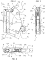
Figure 1 is an overall view depicting the use of the fall-prevention device according to the invention; -
Figures 2, 3 and 4 are some views of a possible embodiment of the fall-prevention device according to the invention, in whichfigure 2 is a plant view,figure 3 is a side view from the top of the lever, whereasfigure 4 is a top view; -
Figure 5 is another plant view depicting the fall-prevention device in the open position of the lever and in the release position of the stop, in which the secondary plate has been omitted for a better visualization; -
Figures 6a-e depict the various steps of connecting the fall-prevention device according to the invention to the securing cable; -
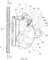
Figure 7 shows the fall-prevention device before its connection to the cable in an intermediate position; -
Figure 7a is an enlarged view of the lever and stop in the intermediate position, in which the part of the spring has been omitted for ease of illustration; -
Figures 8a-e depict the various steps of removing the fall-prevention device according to the invention from the securing cable; -
Figure 9 shows the fall-prevention device connected to the cable in an intermediate position; -
Figure 10 shows another possible embodiment of the fall-prevention device according to the present invention; -
Figure 10a is an enlarged view of the lever and stop in the intermediate position, in which the part of the spring has been omitted for ease of illustration. - Referring to the attached
figures 1 - 9 , a possible embodiment of the fall-prevention device 1 according to the present invention will be described hereinafter. What described referring to these figures applies also to an embodiment depicted infigure 10 , different from the embodiment offigures 1-9 only for the different shape of the abutment surfaces 80a, 80b of thelever 16 and for the respective engagingsurfaces - For example, as visible in
figure 1 , the movable fall-prevention device 1 is generally part of individual equipment protecting against high falls and denoted withnumeral reference 2 which comprises, in addition to said fall-prevention device 1, aharness 3 comprising at least oneanchoring ring 4 with a hooking karabiner 5, or similar connecting elements. The fall-prevention device 1 is then intended to be removably connected to avertical securing support 6 fastened, for example, to aservice post 7. The movable fall-prevention device 1, hereinafter also referred only as fall-prevention device, in its use position, i.e. connected to theharness 3, can be voluntarily moved upwards HA or downwards BA by normally sliding (i.e. at the user's climb or descent speed) along a cable or rope 6 (preferably substantially vertical), which constitutes the securing support. - In case of fall, corresponding to an accelerated descent speed, the movable fall-prevention device blocks on the
cable 6. It will be understood that theuser 8 will be therefore able to climb or descend along apost 7 by leaving the fall-prevention device to slide upwards HA or downwards BA along thesafety cable 6, while he/she will be assured against falls since the fall-prevention device 1 is blocked on thecable 6 constituting the securing support. - The fall-
prevention device 1 comprises amain body 1a comprising apassage 40 for the insertion/removal of the securingsupport 6 in/from a groove orhollow profile 9, preferably straight having axis YY' and intended to receive the securingcable 6. In the following it will be referred particularly to a securingcable 6, however the possibility of using the fall-prevention device 1 on different securing support is not excluded. - As better detailed in the following, the securing
cable 6 is restrained in thegroove 9 by alever 16 provided with a lockingcam 10 designed to engage thecable 6 and prevent the sliding thereof inside the groove, de facto determining the blocking of the fall-prevention device on thecable 6, in case of fall. - According to an aspect of the present invention, the
body 1a of the device comprises amain plate 12a and asecondary plate 12b facing to one another. The twoplates hollow profile 9 is constituted by thewall 11a of themain plate 12a, whosefirst side edge 13a is bent parallel to said wall, so that to form a preferablysemicircular groove 9, whereas thesecond side edge 14a is in the wall plane and curved. It has to be noticed that the groove preferably has semicircular profile with vertical axis (YY') and substantially has the size of the cable orrope 6 both intended to be housed in its inside. - The
lever 16 comprising the lockingcam 10 is constrained to thedevice 1 so that to be rotationally movable with respect to a transversal axis XX'. Thelever 16 is preferably rotatable around a pivot constrained to thebody 1a of the device. - It has to be noticed that the
second side edge 14a of themain wall 12a can be shape to be a substantially circular lower ramp having radius R1 centered on the axis XX'. - As mentioned, the body of the movable fall-prevention device comprises, in addition to the
main plate 12a described before and forming thegroove 9, asecondary plate 12b. The latter is integral with the main body to be parallel thereto and is spaced out of a distance (d) in order to constitute a space (e) between the two plates intended to move thelever 16, in addition to thelongitudinal passage 40 for the insertion/removal of thecable 6. - According to a possible embodiment, the secondary plate is configured substantially identical to the
wall 11a of themain plate 12a. In this way, it is constituted by a wall 11b and comprises a firststraight side wedge 13b, whereas thesecond side edge 14b is in the wall plane and curved to constitute a lower ramp. - The
passage 40 is limited laterally by thefirst edge 13b of themain plate 12a and thefirst edge 13a of thesecondary plate 12b. Obviously, the passage width is larger than the diameter of the cable orrope 6, both intended to be engaged therein. According to a possible embodiment, it has to be noticed that thepassage 40 extends parallel to the axis YY' of thegroove 9. - The above mentioned
lever 16 is arranged so as to be rotationally movable around the transversal axis XX', preferably at a pivot allowing such rotation. It is arranged so that to move inside thebody 1a between the twoplates main plate 12a and thesecondary plate 12b. - The
lever 16 is rotatably assembled around an axis or pivot 21 extending between the two plates so that its hookingend 16" protrudes outside of theramps plates - In fact, the
lever 16 substantially comprises the lockingcam 10 substantially at one of the ends (locking end 16') and a hookinghole 23, substantially at the other free end (hookingend 16"), intended to receive a karabiner 5 or similar means connecting to the user and, in particular, to the user's harness. - The hooking
hole 23 is cylindrical and its axis QQ' is arranged at a distance L1 from the axis XX' greater than the value of the radius R1 of the ramp summed to radius of thehole 23, so that itsperipheral wall 24 is at a distance L2 from the axis XX' greater than the radius R1. - As mentioned, at the side opposite to the hooking
hole 23, thelever 16 comprises acam 10, for example comprising alocking ramp 25, to guarantee the locking of the fall-prevention device 1 on the securingdevice 6. - The
lever 16 can then take, by rotation around the XX' axis, two limit positions: an open position as depicted infigures 5 ,6d ,8d , and a closed position as depicted infigures 2 ,6a ,8e . - In the closed position, the locking
cam 10 is in contact with the securingcable 10 thus determining the locking thereof due to the friction generated thereon. - It should also be noted that in the closed position, part of the
lever 16 extends at thepassage 40 and prevents the securingcable 6 from being inserted/removed in/from the restraininggroove 9 through thepassage 40. On the contrary, in the open position thelever 16 does not extend at thepassage 40, and then the securingcable 6 can be inserted/removed in/from thegroove 9. - It has to be further noticed that the fall-
prevention device 1 comprises twostops lever 16, downwards by alower stop 28, and upwards by anupper stop 29. - The
lower stop 28 can be made through a cylindrical spacer extending between the twoplates upper stop 29 can be made through another upper cylindrical spacer connecting the upper portion of the twoplates - According to an aspect of the present invention, the
lever 16 is continuously biased towards its closed position by a spring, preferably a torsion spring 27 (visible infigures 3 and 4 ). The latter is useful, on the one hand, to keep the fall-prevention device 1 in position on the securingcable 6 when the karabiner 5 is positioned and removed and, on the other hand, it is useful to guarantee the locking of thedevice 1 in case of fall even before the karabiner 5 secures in turn the lever rotation downwards, i.e. towards its closed position. - According to an aspect of the present invention, the fall-
prevention device 1 comprises astop 50, preferably a rotationally movable stop, movable between an operative position, in which it limits the rotation of thelever 16 in an intermediate position, when thelever 16 is moved from the closed position to the open position, and a release position in which it allows the rotation of thelever 16 in the open position. - In other words, the
device 1 comprises a movable andretractable stop 50 for thelever 16, which is intended to limit the rotation of the latter upwards in an intermediate position. - More in detail, in the intermediate position part of the
lever 16, and in particular of its locking end 16', is placed at thepassage 40 de facto preventing the securingsupport 6 from being removed from the fall-prevention device. - According to a possible embodiment, the
stop 50 is constituted by a rotating by a rotatingpawl 50. - It has to be noticed that the
stop 50 is biased in its operative position by thespring 27. It has to be noticed that, although only onespring 27 acting on thelimit 50 and thelever 16 is provided for biasing these components respectively in their operative position and closed position, distinct elastic elements can be used to bias the two components independently. - The
stop 50 is intended both to limit the rotation of thelever 16 in an intermediate position and to prevent, due to its shape, the securingsupport 6 from disengaging inconveniently through thepassage 40. - In fact, the stop 50 (or pawl) further comprises a
safety arm 51 preventing the insertion/removal of the securingsupport 6 in/from thepassage 40 when thestop 50 is in the operative position and allowing the insertion/removal of the securingsupport 6 in/from thepassage 40 when thestop 50 is in the release position. - More in detail the pawl, thanks to its
lateral safety arm 51, constitutes an obstacle locking the undesirable disengagement of the securingsupport 6 through thepassage 40. - Advantageously, it follows that the operative position of the
stop 50 corresponds to a closed position of thepassage 40, whereas the release position of the stop allows the insertion/removal of the securingsupport 6 in/from thepassage 40. - Advantageously, as mentioned, the pawl constituting a further safety system of the device, is biased in its operative and closed stop position by a
spring 27, which can advantageously be the same spring biasing thelever 16 in the closed position. According to an aspect of the present invention, thestop 50 further comprises an activatingarm 55. Thearm 55 is designed so that to protrude outside of thebody 1a of the device when thestop 50 is in the operative position. - Moreover, the
stop 50 comprises an engagingportion 53 comprising at least oneengaging surface lever 16 and, in particular, anabutment portion 80 of thelever 16 in the intermediate position. Theabutment portion 80 of thelever 16 comprises at least oneabutment surface 80a intended to cooperate, in the intermediate position, with at least one corresponding engagingsurface 53a of thestop 50 to lock thestop 50 in its operative position. - The engaging
surface 53, and in particular the at least oneengaging surface 53a, is preferably arranged on alower arm 52 of thestop 50, preferably at one end of the lower arm. - According to a possible embodiment, the pawl (stop) is constituted by three arms, i.e. a
lateral safety arm 51 intended to lock the undesirable disengagement of the securingsupport 6 through thepassage 40, alower arm 52 comprising the engagingportion 53 that engages thelever 16 and is intended to limit the lever rotation in an intermediate position (when the lever is rotated from the operative position towards the closed position), as well as an activatingarm 55. - According to a possible embodiment, the pawl (stop) is assembled as rotationally movable around a transversal axis (pivot) 58 arranged between the main plate and the secondary plate in the upper part of the fall-prevention device, substantially in the extension of the
first edge 13b of the secondary plate. By doing so, thelateral safety arm 51 goes beyond theedge 13b until it reaches theedge 13a, thereby blocking thepassage 40 when the pawl is in the operative position and acting as stop for thelever 16. On the contrary, when the stop is rotated to the release position, thesafety arm 51 clears thepassage 40. - In other words, the
stop 50 is movable and retractable between an operative position named "safety position", which blocks thepassage 40 and limits the lever rotation in its intermediate position, and an idle release position. The user, by simply acting on the stop and in particular on the activatingarm 55 to move it from its operative position to the release position and allow thelever 16 to pass from its intermediate position to its open position. - As afore said, the body of the
device 1a is shaped to house the activating arm for at least part of the movement between the operative position and the release position. In fact, the activating arm can be activated by the user only for a portion of its movement from the operative position to the release position. It follows that the complete movement of the stop in its release position can be completed only by the contact with thelever 16 at itsown back surface 52b. - In fact, the movement driven by the user on the outside of the device of the activating arm can be carried out only until the profile P of the
arm 55 is at theside walls figures 6b, 6c andfigures 8b, 8c ). For the remaining part of the movement towards the release position, the activatingarm 55 is housed inside thebody 1a of the device. - The contact of the
abutment portion 80 of thelever 16 with theback surface 52b of the stop will cause the displacement of the latter to the release position (see the movement fromfigure 6c to figure 6d and fromfigure 8c to figure 8d ). It has to be further noticed that the stop can be advantageously provided with aroll 56, or similar element to aid the sliding, at itssafety arm 51 to guarantee a better guide of the securingsupport 6 at the upper end of thegroove 9. - Returning to the intermediate position of the
lever 16, thestop 50 limits the rotation of thelever 16 in such position by anabutment portion 80 of the lever cooperating with the engagingportion 53 of thestop 50 that, as mentioned, is preferably arranged at alower arm 52 of the stop. - More in detail, according to an aspect of the present invention, the
lever 16 comprises at least oneabutment surface 80a for anengaging surface 53a of thestop 50. In particular, theabutment surface 80a limits the rotation of thestop 50 away from its own operative position towards the release position. - Advantageously, the presence of the
abutment surface 80a allows to prevent the rotation movement of the stop towards the release portion when the intermediate position of thelever 16 has been reached. - In fact, if in the intermediate position (visible for example in
figures 7 ,7a ,9 ,10 and10a ) the user acts on the activatingarm 55 of the stop, the rotation is effectively countered by the presence of theabutment surface 80a. - According to an aspect of the present invention, for example visible in the figures, the
lever 16 and in particular itsabutment portion 80 comprises afirst abutment surface 80a and asecond abutment surface 80b. - As mentioned, the
first abutment surface 80a is adapted to limit the rotation of thestop 50 away from its own operative position towards the release position. According to a possible embodiment, such as for example visible infigures 1 - 9 , thefirst abutment surface 80a and asecond abutment surface 80b are substantially perpendicular to one another. - In particular, the
first abutment surface 80a is adapted to limit the rotation of thestop 50 towards the release position, whereas thesecond abutment surface 80b is adapted to limit the rotation of thelever 16 in the intermediate position when the latter is rotated from the open position to the closed position. By doing so, theabutment portion 80 of thelever 16 takes a substantially stepped form allowing to effectively avoid any movement of thestop 50 when thelever 16 is in the intermediate position in engagement with the engagingportion 53 of thestop 50. - According to a further possible embodiment visible in
figure 10 , the twoabutment surfaces surfaces stop 50. - In general, it has to be noticed that the at least two
abutment surfaces - It has to be further noticed that, according to a possible embodiment (such as for example in
figures 1 - 9 ) in the intermediate position of thelever 16, theabutment surface 80a is arranged substantially perpendicular to the movement path T of thestop 50 from the operative position to the release position. In other words, according to this embodiment, theabutment surface 80a is tilted by an angle α substantially equal to 90° with respect to the movement path T of thestop 50. - Advantageously, the
abutment surface 80a provides an effective obstacle for the undesirable movement of thestop 50, for example as a consequence of an unintentional activation of the activatingarm 55 by the user. - It has to be noticed that the expression "substantially perpendicular to the path" herein means that the
abutment surface 80a is arranged substantially perpendicular to the movement direction, and in particular substantially perpendicular to the tangent T' to the path, or perpendicular to the direction of the velocity vector, the engagingportion 53 of the stop and in particular the engagingportion 53a intended to cooperate with theabutment surface 80a. - Since the stop is preferably rotationally movable, in this case (such as for example visible in the figure), the movement path will be circular. The expression "substantially perpendicular to the circular path" means that the
abutment surface 80a is substantially perpendicular to the tangent T' to the path, or to the direction of the velocity vector (tangential velocity) of theengaging surface 53a of the stop. - As previously mentioned, the
abutment surface 80a can be arranged as tilted by an angle substantially comprised between 90° and 135° with respect to the movement path T of the stop (and in particular of its engaging surface) from the operative position towards the release position. - In other words, the
abutment surface 80a can be arranged substantially perpendicular to the path T of the stop (and therefore substantially directed along the perpendicular to the path), as in the embodiment offigures 1-9 , or it is tilted with respect to the perpendicular to the path by an angle up to about 45° (as in the embodiment offigure 10 ). In other words, theabutment surface 80a is substantially perpendicular to the path or is tilted by an angle up to 45° with respect to the path perpendicular. - In the embodiment depicted in
figure 10 , in the intermediate position of thelever 16, theabutment surface 80a is arranged as tilted by an angle α substantially equal to 135° with respect to the movement path T of thestop 50 from the operative position to the release position. In particular, in the intermediate position of thelever 16, theabutment surface 80a is arranged as tilted by an angle equal to 135° with respect to the tangent of the movement path T of thestop 50 from the operative position to the release position. - According to the embodiment depicted in
figure 10 , the lever comprises asecond abutment surface 80b intended to cooperate with a secondengaging surface 53b of thestop 50. - The first and the
second abutment surfaces engaging surfaces - According to an aspect of the present invention, the
abutment portion 80 is designed substantially complementary to the engagingsurface 53 of thestop 50. For example, theabutment portion 80 and the engagingportion 53 both intended to contact one another in the intermediate position can be, for example, both step-shaped and complementary to one another, or can be wedge-shaped and intended to cooperate with a corresponding seat, in order to achieve the effect of efficiently prevent the undesirable movement of the stop towards the release position. - For example, as visible in the attached
figures 1-9 , the engagingportion 53 arranged at the end of thelower arm 52 has a substantially stepped-shape able to couple with theabutment portion 80 also substantially stepped, through the twoabutment surfaces - It has to be further noticed that, according to an aspect of the present invention, the
abutment portion 80 is arranged on alateral arm 16a of thelever 16. - Preferably, the
abutment portion 80 and in particular the at least oneabutment surface 80a, is arranged at the end of thearm 16a. - The
arm 16a extends laterally from thelever 16, preferably in a portion comprised between the rotation axis of the lever and the hookinghole 23. - According to a possible embodiment, the
lateral arm 16a of thelever 16 has a substantially curved shape, preferably substantially circular, that follows the profile of thebody 1a of the device at theedges - It has to be further noticed that, according to an aspect of the present invention, the
lever 16 comprises aseat 16b designed to accommodate at least part of the stop 50 (as visible infigures 6c and8c ) and, in particular, thelower arm 52 when the latter is rotated towards the release position. - Preferably, the
seat 16b is arranged under thelateral arm 16a of thelever 16 and, in particular, between the rotation axis of the lever and the point from which thelateral arm 16a extends from the profile of thelever 16. - The
device 1, during the use, can be in three different possible positions, which will be better detailed in the following. In particular, thefigures 6a ,8a show the open position in which thecable 6 can be inserted/removed in/from the device. In such a position, thelever 16 is in its open position and thestop 50 is in the release position. The intermediate position of thelever 16 is, for example, visible infigures 7 ,9 and10 in which thestop 50 is in its own operative position. In such a position, as described above, theabutment portion 80 provided with the at least oneabutment surface 80a, allows to effectively prevent the undesirable movement of the stop away from its own operative position. - The locking position is, for example, visible in
figure 6e in which thelever 16 is in its own closed position with the lockingcam 10 in contact with the cable, and thestop 50 is in its own operative position. It has to be noticed that the fall-prevention device 1 is in the open position while the cable is inserted and removed. The fall-prevention device, when used as connected to the cable, can be used during climb or descent. During the climb, the user rotates thelever 16 upwards (HA) in accordance with R1b (anticlockwise rotation). By doing so, thelever 16 reaches the intermediate position, i.e. theportion 80 abuts on theend 53 of thearm 52. As mentioned, in this position thelever 16 prevents the cable from releasing thegroove 9 and, when thelever 16 is released, the latter rotates again downwards in accordance with (R2), thus causing the fall-prevention device to lock on the cable. - During the descent, the weight of the fall-
prevention device 1 and thespring 27 allow thelever 16 to stay in the intermediate position. - In this way, the user can descend without intervening on the fall-
prevention device 1. In case of fall or sudden descent, thelever 16 turns downwards (BA) in accordance with (R2), whereas the lockingcam 25 tightens the cable (6). - In the intermediate position, between the cable and the
cam 10 there is some play allowing the free sliding upwards (HA) and downwards (BA) at the same time. However, as soon as a fall happens, the fall-prevention device 1 returns immediately in its locking position, as depicted infigure 8a . -
Figures 6a-e depict the various steps of connecting (assembling) the fall-prevention device according to the present invention to the securing cable. - It has to be noticed that, according to a preferred use mode, during insertion and removal operations of the
cable 6 in the device, a karabiner 5 is advantageously connected to thehole 23 and connects the device to the user's harness, so that the tool is constrained to the user and cannot be lost. - Returning back to the steps of connecting the
device 1 to thecable 6, the user operates, for example by leaning thefirst plate 12a of the fall-prevention device 1 in the palm of the right hand, the activatingarm 55 of the stop downwards according to R1a (clockwise) to disengage thepassage 40 for the cable. - It has to be noticed that, according to an aspect of the present invention, the
body 1a of thedevice 1 is shaped so that the upper surface of the activating arm 55 (and in particular the upper profile (edge) P of the activating arm) is arranged at the upper profile (edge) 15a, 15b of the device body before reaching the release position. - In other words when the user activates the activating
arm 55 from the operative position of the stop towards the release position, at one point it will encounter the profile (edge stop 50 has not reached yet its release position. - In fact, in such position (intermediate position of the stop), the
stop 50 and in particular thesafety arm 51 does not disengage thepassage 40 completely, as shown infigure 6b . At this point, the user rotates thelever 16 to the open position in accordance with (R1b), as shown infigure 6c . The movement of thelever 16 towards the open position determines the contact of theabutment portion 80 with theback surface 52b of the stop and moves it to its release position. - In particular, the
lateral arm 16a of thelever 16 is designed so that, in the open position of thelever 16, it contacts the stop and, in particular, thelower arm 52 to move it to the release position, as shown infigure 6d . In such a position, thestop 50 and in particular thesafety arm 51 disengages thepassage 40 completely, the coupling of the fall-prevention device with thecable 6 is thus possible. The user then engages thecable 6 in thegroove 9 and releases thelever 16 and thestop 50 that, due to thespring 27, will move to the close position and the operative position, respectively, as depicted infigure 6e . - The method of connecting the fall-
prevention device 1 to the cable therefore comprises the user's action both onto thestop 50 and thelever 16. As shown infigure 6b , before raising thelever 16 it is necessary to rotate the activatingarm 55 of thestop 50 in accordance with (R1a) to move the stop away from its operative position, otherwise the lever, during the movement towards the open position, would reach the intermediate contact position of theabutment portion 80 with the engagingportion 53 of the stop (for example as shown infigure 7 ). - Once the process of connecting the fall-prevention device to the cable is ended, the
lever 16 is biased by thespring 27 and turns downwards in accordance with (R2) until the lockingcam 25 tightens thecable 6 by restraining it in thegroove 9, while the stop blocks thepassage 40 by means of itssafety arm 51. - In the position depicted in
figures 6e ,8a , the fall-prevention device 1 is locked so that to avoid any undesirable descent downwards (BA) and prevent the user's fall, but it might be moved upwards (HA) up to its intermediate position of engagement with the stop, by the rotation of thelever 16 upwards in accordance with (R1b).Figures 8a-e depict the various steps of removing the fall-prevention device according to the present invention from the cable. - Starting from a position in which the
lever 16 is not in the intermediate position of engagement with the stop (figure 8a ), the user rotates thestop 50 in accordance with (R1a) towards the release position, as shown in figure 1b. At this point, thelever 16 can be rotated in accordance with (R1b), as shown for example infigure 8c , until theabutment portion 80 of thelever 16 engages theback surface 52b (or back) of thearm 52 of thestop 50 and thestop 50 is involved in completing its rotation and then the open position of the lever is reached. As mentioned above referring to the assembling, the movement of thelever 16 to its own open position terminates the movement of the stop to its own release position, as shown infigure 8d . At this point, the fall-prevention device can be disengaged from thecable 6 and the stop and thelever 16 can be both released, as shown infigure 8e . - The process of removing the fall-prevention device from the cable according to the present invention is particularly safe thanks to a necessary sequential and consecutive action on the
arm 55 of thestop 50 and on thelever 16, to cause the removal of the fall-prevention device. As shown infigure 9 , as a matter of fact, the only rotation of thelever 16 is not sufficient to unlock the fall-prevention device. Once the fall-prevention device is in the intermediate position engaging thelever 16 with the stop, such as for example visible infigure 9 , even an action onto thearm 55 of thestop 50 cannot cause the rotation of the stop towards the release position, just thanks to the engagement with the abuttingportion 80. In fact, thanks particularly to the presence of theabutment surface 80a, the rotation of the stop from its operative position to the release position can be effectively hampered. This arrangement according to the present invention guarantees high safety allowing involuntary removals of the fall-prevention device from the cable during use.
Claims (15)
- Movable fall-prevention device (1) for a securing support (6), comprising a main body (1a) having a passage (40) for the insertion/removal of the securing support in/from a restraining groove (9), wherein said securing support (6) is restrained through a lever (16) rotating between an open position and a closed position, and wherein one of the lever ends comprises a locking cam (10, 25) and the other free end comprises a hole (23) intended to receive a karabiner (5), the device further comprising a stop (50) movable between an operative position, in which it limits the rotation of the lever (16) in an intermediate position when the lever is moved from the closed position to the open position, and a release position in which it allows the rotation of the lever (16) in the open position, characterized in that said lever (16) comprises at least one abutment surface (80a) cooperating, in said intermediate position, with at least one corresponding engaging surface (53a) of the stop (50) to lock the stop (50) to the operative position, wherein said abutment surface (80a) is tilted by an angle (α) substantially comprised between 90° and 135° with respect to the movement path (T) of the stop (50) from the operative position towards the release position.
- Fall-prevention device according to claim 1, wherein said at least one abutment surface (80a) in said intermediate position intercepts said at least one corresponding engaging surface (53a) of the stop (50) to hamper the movement of the stop (50) from its operative position towards the release position.
- Fall-prevention device according to claim 1 or 2, wherein said stop (50) is rotationally movable and the abutment surface (80a) is tilted by an angle (α) substantially comprised between 90° and 135° with respect to the tangent (T1) to the movement path (T) of the stop (50).
- Fall-prevention device (1) according to any one of the preceding claims, wherein said abutment surface (80a) is configured substantially complementary to said engaging surface (53a).
- Fall-prevention device (1) according to any one of the preceding claims, wherein said at least one abutment surface (80a) is arranged on a lateral arm (16a) of said lever (16).
- Fall-prevention device (1) according to any one of the preceding claims, characterized in that said lever (16) comprises a seat (16b) to receive at least part of said stop (50) when the latter is rotated towards said release position.
- Fall-prevention device (1) according to any one of the preceding claims, characterized in that said lever (16) comprises at least two abutment surfaces (80a, 80b) cooperating with at least two engaging surfaces (53a, 53b) of the stop (50), preferably
said at least two abutment surfaces (80a, 80b) are tilted one to another. - Fall-prevention device according to claim 7, wherein said at least two abutment surfaces (80a, 80b) are substantially perpendicular one to another, or
said at least two abutment surfaces (80a, 80b) are substantially wedge shaped. - Fall-prevention device (1) according to any one of preceding claims 7 or 8, wherein a first abutment surface (80b) limits the rotation of the lever in the intermediate position and a second abutment surface (80a) limits the rotation of the stop (50) towards the release position.
- Fall-prevention device (1) according to any one of the preceding claims, wherein said stop (50) is clockwise rotatable (R1a) from said operative position towards said release position.
- Fall-prevention device (1) according to any one of the preceding claims, wherein said lever (16) is anticlockwise rotatable (R1b) from said closed position towards said open position.
- Fall-prevention device (1) according to any one of the preceding claims, wherein the stop (50) comprises an activating arm (55) to drive the movement of the stop from said operative position towards said release position, preferably said activating arm (55) is arranged outside of said main body (1a) when said stop is in the operative position to be manually driven, the body (1a) of the device being shaped to house the activating arm (55) for at least part of the movement from said operative position to said release position.
- Fall-prevention device (1) according to claim 12, wherein the activating arm (55) comprises a profile (P), the profile (P) is arranged at an edge (15a, 15b) of the body (1a) of the device, before reaching said release position.
- Fall-prevention device (1) according to any one of the preceding claims, wherein at least part of the lever (16) is contacting the stop (50), preferably a back surface (52b) of the stop (50), to guide at least part of the movement thereof towards said release position.
- Method of installing/removing a fall-prevention device (1) according to claims 1 - 14 to a securing support (6), wherein said fall-prevention device comprises a main body (1a) having a passage (40) for the insertion/removal of the securing support in/from a restraining groove (9), wherein said securing support (6) is restrained through a lever (16) rotating between an open position and a closed position, and wherein one of the lever ends comprises a locking cam (10, 25) and the other free end comprises a hole (23) intended to receive a karabiner (5), the device further comprising a stop (50) movable between an operative position, in which it limits the rotation of the lever (16) in an intermediate position when the lever is moved from the closed position to the open position, and a release position in which it allows the rotation of the lever (16) in the open position, the method comprising the step of moving the stop (50) from its operative position towards the release position in order to rotate the lever (16) from the closed position to the open position, thus allowing the insertion/removal of the securing support (6) in/from the groove (9) of the device.
Applications Claiming Priority (2)
| Application Number | Priority Date | Filing Date | Title |
|---|---|---|---|
| ITUB2015A004778A ITUB20154778A1 (en) | 2015-10-27 | 2015-10-27 | FALL ARREST DEVICE. |
| PCT/IB2016/056428 WO2017072667A1 (en) | 2015-10-27 | 2016-10-26 | Fall-prevention device |
Publications (2)
| Publication Number | Publication Date |
|---|---|
| EP3368164A1 EP3368164A1 (en) | 2018-09-05 |
| EP3368164B1 true EP3368164B1 (en) | 2022-11-30 |
Family
ID=55359573
Family Applications (1)
| Application Number | Title | Priority Date | Filing Date |
|---|---|---|---|
| EP16809522.2A Active EP3368164B1 (en) | 2015-10-27 | 2016-10-26 | Fall-prevention device |
Country Status (5)
| Country | Link |
|---|---|
| EP (1) | EP3368164B1 (en) |
| ES (1) | ES2940474T3 (en) |
| IT (1) | ITUB20154778A1 (en) |
| PL (1) | PL3368164T3 (en) |
| WO (1) | WO2017072667A1 (en) |
Families Citing this family (2)
| Publication number | Priority date | Publication date | Assignee | Title |
|---|---|---|---|---|
| CN109529218B (en) * | 2018-12-27 | 2023-11-21 | 济南奔速超伦机械设备有限公司 | Rope grab |
| FR3141350A1 (en) | 2022-10-27 | 2024-05-03 | Reflet | Mobile fall arrest device |
Family Cites Families (3)
| Publication number | Priority date | Publication date | Assignee | Title |
|---|---|---|---|---|
| US5265696A (en) * | 1992-01-31 | 1993-11-30 | D B Industries, Inc. | Ladder climbing safety clamp |
| FR2736273A1 (en) * | 1995-07-03 | 1997-01-10 | Sk Sarl | MOBILE FALL PROTECTION FOR LOCKING SUPPORT |
| FR2820641B1 (en) * | 2001-02-14 | 2003-04-04 | Sk | MOBILE FALL PROTECTION FOR LOCKING SUPPORT |
-
2015
- 2015-10-27 IT ITUB2015A004778A patent/ITUB20154778A1/en unknown
-
2016
- 2016-10-26 ES ES16809522T patent/ES2940474T3/en active Active
- 2016-10-26 WO PCT/IB2016/056428 patent/WO2017072667A1/en unknown
- 2016-10-26 PL PL16809522.2T patent/PL3368164T3/en unknown
- 2016-10-26 EP EP16809522.2A patent/EP3368164B1/en active Active
Also Published As
| Publication number | Publication date |
|---|---|
| EP3368164A1 (en) | 2018-09-05 |
| ES2940474T3 (en) | 2023-05-08 |
| WO2017072667A1 (en) | 2017-05-04 |
| PL3368164T3 (en) | 2023-05-02 |
| ITUB20154778A1 (en) | 2017-04-27 |
Similar Documents
| Publication | Publication Date | Title |
|---|---|---|
| TWI630941B (en) | Fall arrest safety apparatus on a rope with clamping function | |
| US8225905B2 (en) | Ascender device with cam for belaying on a fixed rope | |
| US7080716B2 (en) | Movable fall prevention device for a belay support | |
| ES2153947T5 (en) | MOBILE ANTI-DEVICE DEVICE FOR FLEXIBLE INSURANCE SUPPORT. | |
| US6530454B1 (en) | Two-way locking device for height safety apparatus | |
| EP2796172B1 (en) | Fall arrest device | |
| EP3368164B1 (en) | Fall-prevention device | |
| EP3341085B1 (en) | Shuttle device | |
| US20140196989A1 (en) | Fall arrest safety apparatus with blocking on a rope | |
| US20140262610A1 (en) | Systems for Assisted Braking Belay with a Lever Disengagement Mechanism | |
| JPH09511165A (en) | Detachable vertical fall prevention device | |
| US10619417B2 (en) | Pass-through cable grab system | |
| WO2004075993A1 (en) | Safety devices | |
| WO2013053685A2 (en) | Fall arrest device | |
| GB2517675A (en) | Fall arrest device and a restraining device therefor | |
| ES2643212T3 (en) | Safety system for a sloping roof | |
| JP2020193461A (en) | Hook device and fall prevention tool for scaffold | |
| GB2522721A (en) | Fall arrest device | |
| US20050061588A1 (en) | Safe auto-locking belay override mechanism | |
| EP4360716A1 (en) | Mobile fall protection device | |
| GB2566574A (en) | Fall arrest device | |
| KR200477605Y1 (en) | Safety Device for Entry Scene of Fire |
Legal Events
| Date | Code | Title | Description |
|---|---|---|---|
| STAA | Information on the status of an ep patent application or granted ep patent |
Free format text: STATUS: UNKNOWN |
|
| STAA | Information on the status of an ep patent application or granted ep patent |
Free format text: STATUS: THE INTERNATIONAL PUBLICATION HAS BEEN MADE |
|
| PUAI | Public reference made under article 153(3) epc to a published international application that has entered the european phase |
Free format text: ORIGINAL CODE: 0009012 |
|
| STAA | Information on the status of an ep patent application or granted ep patent |
Free format text: STATUS: REQUEST FOR EXAMINATION WAS MADE |
|
| 17P | Request for examination filed |
Effective date: 20180320 |
|
| AK | Designated contracting states |
Kind code of ref document: A1 Designated state(s): AL AT BE BG CH CY CZ DE DK EE ES FI FR GB GR HR HU IE IS IT LI LT LU LV MC MK MT NL NO PL PT RO RS SE SI SK SM TR |
|
| AX | Request for extension of the european patent |
Extension state: BA ME |
|
| DAV | Request for validation of the european patent (deleted) | ||
| DAX | Request for extension of the european patent (deleted) | ||
| REG | Reference to a national code |
Ref country code: HK Ref legal event code: DE Ref document number: 1259676 Country of ref document: HK |
|
| GRAP | Despatch of communication of intention to grant a patent |
Free format text: ORIGINAL CODE: EPIDOSNIGR1 |
|
| STAA | Information on the status of an ep patent application or granted ep patent |
Free format text: STATUS: GRANT OF PATENT IS INTENDED |
|
| INTG | Intention to grant announced |
Effective date: 20220512 |
|
| RIN1 | Information on inventor provided before grant (corrected) |
Inventor name: PAGLIOLI, CARLO |
|
| GRAS | Grant fee paid |
Free format text: ORIGINAL CODE: EPIDOSNIGR3 |
|
| RIN1 | Information on inventor provided before grant (corrected) |
Inventor name: PAGLIOLI, CARLO |
|
| RAP3 | Party data changed (applicant data changed or rights of an application transferred) |
Owner name: ALUDESIGN S.P.A. |
|
| GRAA | (expected) grant |
Free format text: ORIGINAL CODE: 0009210 |
|
| STAA | Information on the status of an ep patent application or granted ep patent |
Free format text: STATUS: THE PATENT HAS BEEN GRANTED |
|
| AK | Designated contracting states |
Kind code of ref document: B1 Designated state(s): AL AT BE BG CH CY CZ DE DK EE ES FI FR GB GR HR HU IE IS IT LI LT LU LV MC MK MT NL NO PL PT RO RS SE SI SK SM TR |
|
| REG | Reference to a national code |
Ref country code: CH Ref legal event code: EP Ref country code: GB Ref legal event code: FG4D |
|
| REG | Reference to a national code |
Ref country code: AT Ref legal event code: REF Ref document number: 1534213 Country of ref document: AT Kind code of ref document: T Effective date: 20221215 Ref country code: DE Ref legal event code: R096 Ref document number: 602016076650 Country of ref document: DE |
|
| REG | Reference to a national code |
Ref country code: IE Ref legal event code: FG4D |
|
| REG | Reference to a national code |
Ref country code: NL Ref legal event code: FP |
|
| REG | Reference to a national code |
Ref country code: LT Ref legal event code: MG9D |
|
| PG25 | Lapsed in a contracting state [announced via postgrant information from national office to epo] |
Ref country code: SE Free format text: LAPSE BECAUSE OF FAILURE TO SUBMIT A TRANSLATION OF THE DESCRIPTION OR TO PAY THE FEE WITHIN THE PRESCRIBED TIME-LIMIT Effective date: 20221130 Ref country code: PT Free format text: LAPSE BECAUSE OF FAILURE TO SUBMIT A TRANSLATION OF THE DESCRIPTION OR TO PAY THE FEE WITHIN THE PRESCRIBED TIME-LIMIT Effective date: 20230331 Ref country code: NO Free format text: LAPSE BECAUSE OF FAILURE TO SUBMIT A TRANSLATION OF THE DESCRIPTION OR TO PAY THE FEE WITHIN THE PRESCRIBED TIME-LIMIT Effective date: 20230228 Ref country code: LT Free format text: LAPSE BECAUSE OF FAILURE TO SUBMIT A TRANSLATION OF THE DESCRIPTION OR TO PAY THE FEE WITHIN THE PRESCRIBED TIME-LIMIT Effective date: 20221130 Ref country code: FI Free format text: LAPSE BECAUSE OF FAILURE TO SUBMIT A TRANSLATION OF THE DESCRIPTION OR TO PAY THE FEE WITHIN THE PRESCRIBED TIME-LIMIT Effective date: 20221130 |
|
| REG | Reference to a national code |
Ref country code: ES Ref legal event code: FG2A Ref document number: 2940474 Country of ref document: ES Kind code of ref document: T3 Effective date: 20230508 |
|
| PG25 | Lapsed in a contracting state [announced via postgrant information from national office to epo] |
Ref country code: RS Free format text: LAPSE BECAUSE OF FAILURE TO SUBMIT A TRANSLATION OF THE DESCRIPTION OR TO PAY THE FEE WITHIN THE PRESCRIBED TIME-LIMIT Effective date: 20221130 Ref country code: LV Free format text: LAPSE BECAUSE OF FAILURE TO SUBMIT A TRANSLATION OF THE DESCRIPTION OR TO PAY THE FEE WITHIN THE PRESCRIBED TIME-LIMIT Effective date: 20221130 Ref country code: IS Free format text: LAPSE BECAUSE OF FAILURE TO SUBMIT A TRANSLATION OF THE DESCRIPTION OR TO PAY THE FEE WITHIN THE PRESCRIBED TIME-LIMIT Effective date: 20230330 Ref country code: HR Free format text: LAPSE BECAUSE OF FAILURE TO SUBMIT A TRANSLATION OF THE DESCRIPTION OR TO PAY THE FEE WITHIN THE PRESCRIBED TIME-LIMIT Effective date: 20221130 Ref country code: GR Free format text: LAPSE BECAUSE OF FAILURE TO SUBMIT A TRANSLATION OF THE DESCRIPTION OR TO PAY THE FEE WITHIN THE PRESCRIBED TIME-LIMIT Effective date: 20230301 |
|
| PG25 | Lapsed in a contracting state [announced via postgrant information from national office to epo] |
Ref country code: SM Free format text: LAPSE BECAUSE OF FAILURE TO SUBMIT A TRANSLATION OF THE DESCRIPTION OR TO PAY THE FEE WITHIN THE PRESCRIBED TIME-LIMIT Effective date: 20221130 Ref country code: RO Free format text: LAPSE BECAUSE OF FAILURE TO SUBMIT A TRANSLATION OF THE DESCRIPTION OR TO PAY THE FEE WITHIN THE PRESCRIBED TIME-LIMIT Effective date: 20221130 Ref country code: EE Free format text: LAPSE BECAUSE OF FAILURE TO SUBMIT A TRANSLATION OF THE DESCRIPTION OR TO PAY THE FEE WITHIN THE PRESCRIBED TIME-LIMIT Effective date: 20221130 Ref country code: DK Free format text: LAPSE BECAUSE OF FAILURE TO SUBMIT A TRANSLATION OF THE DESCRIPTION OR TO PAY THE FEE WITHIN THE PRESCRIBED TIME-LIMIT Effective date: 20221130 Ref country code: CZ Free format text: LAPSE BECAUSE OF FAILURE TO SUBMIT A TRANSLATION OF THE DESCRIPTION OR TO PAY THE FEE WITHIN THE PRESCRIBED TIME-LIMIT Effective date: 20221130 |
|
| PG25 | Lapsed in a contracting state [announced via postgrant information from national office to epo] |
Ref country code: SK Free format text: LAPSE BECAUSE OF FAILURE TO SUBMIT A TRANSLATION OF THE DESCRIPTION OR TO PAY THE FEE WITHIN THE PRESCRIBED TIME-LIMIT Effective date: 20221130 Ref country code: AL Free format text: LAPSE BECAUSE OF FAILURE TO SUBMIT A TRANSLATION OF THE DESCRIPTION OR TO PAY THE FEE WITHIN THE PRESCRIBED TIME-LIMIT Effective date: 20221130 |
|
| REG | Reference to a national code |
Ref country code: DE Ref legal event code: R097 Ref document number: 602016076650 Country of ref document: DE |
|
| PLBE | No opposition filed within time limit |
Free format text: ORIGINAL CODE: 0009261 |
|
| STAA | Information on the status of an ep patent application or granted ep patent |
Free format text: STATUS: NO OPPOSITION FILED WITHIN TIME LIMIT |
|
| 26N | No opposition filed |
Effective date: 20230831 |
|
| PG25 | Lapsed in a contracting state [announced via postgrant information from national office to epo] |
Ref country code: SI Free format text: LAPSE BECAUSE OF FAILURE TO SUBMIT A TRANSLATION OF THE DESCRIPTION OR TO PAY THE FEE WITHIN THE PRESCRIBED TIME-LIMIT Effective date: 20221130 |
|
| PGFP | Annual fee paid to national office [announced via postgrant information from national office to epo] |
Ref country code: NL Payment date: 20231018 Year of fee payment: 8 |
|
| PGFP | Annual fee paid to national office [announced via postgrant information from national office to epo] |
Ref country code: GB Payment date: 20231011 Year of fee payment: 8 |
|
| PGFP | Annual fee paid to national office [announced via postgrant information from national office to epo] |
Ref country code: ES Payment date: 20231109 Year of fee payment: 8 |
|
| PGFP | Annual fee paid to national office [announced via postgrant information from national office to epo] |
Ref country code: IT Payment date: 20231004 Year of fee payment: 8 Ref country code: FR Payment date: 20231013 Year of fee payment: 8 Ref country code: DE Payment date: 20231009 Year of fee payment: 8 Ref country code: CH Payment date: 20231102 Year of fee payment: 8 Ref country code: AT Payment date: 20231019 Year of fee payment: 8 |
|
| PGFP | Annual fee paid to national office [announced via postgrant information from national office to epo] |
Ref country code: PL Payment date: 20231005 Year of fee payment: 8 |