EP3367728B1 - Vorrichtung im zusammenhang mit der steuerung eines festen breitbandzugangsnetzes - Google Patents
Vorrichtung im zusammenhang mit der steuerung eines festen breitbandzugangsnetzes Download PDFInfo
- Publication number
- EP3367728B1 EP3367728B1 EP16857233.7A EP16857233A EP3367728B1 EP 3367728 B1 EP3367728 B1 EP 3367728B1 EP 16857233 A EP16857233 A EP 16857233A EP 3367728 B1 EP3367728 B1 EP 3367728B1
- Authority
- EP
- European Patent Office
- Prior art keywords
- senb
- hnb
- enb
- message
- address
- Prior art date
- Legal status (The legal status is an assumption and is not a legal conclusion. Google has not performed a legal analysis and makes no representation as to the accuracy of the status listed.)
- Active
Links
- 238000000034 method Methods 0.000 claims description 57
- 230000004048 modification Effects 0.000 claims description 37
- 238000012986 modification Methods 0.000 claims description 37
- 238000004891 communication Methods 0.000 description 260
- 238000012545 processing Methods 0.000 description 190
- 238000010586 diagram Methods 0.000 description 73
- 238000012546 transfer Methods 0.000 description 41
- 239000000470 constituent Substances 0.000 description 31
- 238000003860 storage Methods 0.000 description 28
- 230000006870 function Effects 0.000 description 25
- 230000008859 change Effects 0.000 description 24
- 230000009977 dual effect Effects 0.000 description 24
- 230000004044 response Effects 0.000 description 19
- 238000005516 engineering process Methods 0.000 description 13
- 210000004754 hybrid cell Anatomy 0.000 description 13
- 210000004027 cell Anatomy 0.000 description 12
- 230000002776 aggregation Effects 0.000 description 10
- 238000004220 aggregation Methods 0.000 description 10
- 230000006872 improvement Effects 0.000 description 8
- 238000012423 maintenance Methods 0.000 description 8
- 238000005457 optimization Methods 0.000 description 8
- 230000005540 biological transmission Effects 0.000 description 4
- 230000000694 effects Effects 0.000 description 4
- 230000008569 process Effects 0.000 description 4
- 230000001413 cellular effect Effects 0.000 description 3
- 230000001960 triggered effect Effects 0.000 description 3
- 238000012508 change request Methods 0.000 description 2
- NRNCYVBFPDDJNE-UHFFFAOYSA-N pemoline Chemical compound O1C(N)=NC(=O)C1C1=CC=CC=C1 NRNCYVBFPDDJNE-UHFFFAOYSA-N 0.000 description 2
- 241001484445 Disconectes Species 0.000 description 1
- 230000003247 decreasing effect Effects 0.000 description 1
- 230000007774 longterm Effects 0.000 description 1
- 238000010295 mobile communication Methods 0.000 description 1
- 238000002360 preparation method Methods 0.000 description 1
- 230000011664 signaling Effects 0.000 description 1
- 239000013589 supplement Substances 0.000 description 1
- 238000013519 translation Methods 0.000 description 1
Images


Classifications
-
- H—ELECTRICITY
- H04—ELECTRIC COMMUNICATION TECHNIQUE
- H04L—TRANSMISSION OF DIGITAL INFORMATION, e.g. TELEGRAPHIC COMMUNICATION
- H04L45/00—Routing or path finding of packets in data switching networks
- H04L45/74—Address processing for routing
-
- H—ELECTRICITY
- H04—ELECTRIC COMMUNICATION TECHNIQUE
- H04W—WIRELESS COMMUNICATION NETWORKS
- H04W16/00—Network planning, e.g. coverage or traffic planning tools; Network deployment, e.g. resource partitioning or cells structures
- H04W16/24—Cell structures
- H04W16/32—Hierarchical cell structures
-
- H—ELECTRICITY
- H04—ELECTRIC COMMUNICATION TECHNIQUE
- H04W—WIRELESS COMMUNICATION NETWORKS
- H04W92/00—Interfaces specially adapted for wireless communication networks
- H04W92/04—Interfaces between hierarchically different network devices
- H04W92/14—Interfaces between hierarchically different network devices between access point controllers and backbone network device
-
- H—ELECTRICITY
- H04—ELECTRIC COMMUNICATION TECHNIQUE
- H04W—WIRELESS COMMUNICATION NETWORKS
- H04W36/00—Hand-off or reselection arrangements
- H04W36/0005—Control or signalling for completing the hand-off
- H04W36/0055—Transmission or use of information for re-establishing the radio link
- H04W36/0077—Transmission or use of information for re-establishing the radio link of access information of target access point
-
- H—ELECTRICITY
- H04—ELECTRIC COMMUNICATION TECHNIQUE
- H04L—TRANSMISSION OF DIGITAL INFORMATION, e.g. TELEGRAPHIC COMMUNICATION
- H04L61/00—Network arrangements, protocols or services for addressing or naming
- H04L61/50—Address allocation
- H04L61/5007—Internet protocol [IP] addresses
-
- H—ELECTRICITY
- H04—ELECTRIC COMMUNICATION TECHNIQUE
- H04L—TRANSMISSION OF DIGITAL INFORMATION, e.g. TELEGRAPHIC COMMUNICATION
- H04L69/00—Network arrangements, protocols or services independent of the application payload and not provided for in the other groups of this subclass
- H04L69/16—Implementation or adaptation of Internet protocol [IP], of transmission control protocol [TCP] or of user datagram protocol [UDP]
-
- H—ELECTRICITY
- H04—ELECTRIC COMMUNICATION TECHNIQUE
- H04W—WIRELESS COMMUNICATION NETWORKS
- H04W36/00—Hand-off or reselection arrangements
- H04W36/0005—Control or signalling for completing the hand-off
- H04W36/0055—Transmission or use of information for re-establishing the radio link
- H04W36/0069—Transmission or use of information for re-establishing the radio link in case of dual connectivity, e.g. decoupled uplink/downlink
-
- H—ELECTRICITY
- H04—ELECTRIC COMMUNICATION TECHNIQUE
- H04W—WIRELESS COMMUNICATION NETWORKS
- H04W72/00—Local resource management
- H04W72/04—Wireless resource allocation
-
- H—ELECTRICITY
- H04—ELECTRIC COMMUNICATION TECHNIQUE
- H04W—WIRELESS COMMUNICATION NETWORKS
- H04W8/00—Network data management
- H04W8/02—Processing of mobility data, e.g. registration information at HLR [Home Location Register] or VLR [Visitor Location Register]; Transfer of mobility data, e.g. between HLR, VLR or external networks
-
- H—ELECTRICITY
- H04—ELECTRIC COMMUNICATION TECHNIQUE
- H04W—WIRELESS COMMUNICATION NETWORKS
- H04W84/00—Network topologies
- H04W84/02—Hierarchically pre-organised networks, e.g. paging networks, cellular networks, WLAN [Wireless Local Area Network] or WLL [Wireless Local Loop]
- H04W84/10—Small scale networks; Flat hierarchical networks
- H04W84/16—WPBX [Wireless Private Branch Exchange]
-
- H—ELECTRICITY
- H04—ELECTRIC COMMUNICATION TECHNIQUE
- H04W—WIRELESS COMMUNICATION NETWORKS
- H04W88/00—Devices specially adapted for wireless communication networks, e.g. terminals, base stations or access point devices
- H04W88/08—Access point devices
Definitions
- the present invention relates to control of a fixed broadband access (FBA) network.
- FBA fixed broadband access
- a policy and charging rules function transmits, to the fixed broadband access network, the local IP address (i.e., the outer IP address of an IPsec tunnel, the public IP address, or the global IP address) and the UDP port number of a base station received from a packet data network gateway (P-GW), together with quality of service (QoS) information of the PCRF.
- the local IP address i.e., the outer IP address of an IPsec tunnel, the public IP address, or the global IP address
- QoS quality of service
- the fixed broadband access network converts the QoS information into a differentiated service code point (DSCP), applies the DSCP to a line associated with the local IP address and the UDP port number received from the PCRF, and performs control on the band for 3GPP system users.
- DSCP differentiated service code point
- NPL 1 e.g., Figure 9.1.5 and Figure 9.3.4-1 discloses processes as those described above.
- NPL 2 (e.g., Figure 5.7.2.1-1 and Figure A.3-1) discloses a procedure for handover in a home access network.
- NPL 3 (e.g., Figure 10.1.2.8.4-1) discloses a procedure for change of an SeNB in dual connectivity.
- NPL 4 and NPL 5 disclose procedures for a case of using a hybrid cell.
- EP2894903A1 discloses a method for bearer offload from a RAN node referred to as Master RAN node such as Master eNB (MeNB) for E-UTRAN, to a RAN node referred to as Secondary RAN node such as Secondary eNB (SeNB) for E-UTRAN, in dual connectivity operation, wherein before said offload said bearer is or had been handled by said Master RAN node and involves a Local Gateway LGW collocated with said Master RAN node, said method including: providing that after said offload said bearer is handled by said Secondary RAN node and involves said Local Gateway LGW collocated with said Master RAN node.
- Master RAN node such as Master eNB (MeNB) for E-UTRAN
- Secondary RAN node such as Secondary eNB (SeNB) for E-UTRAN
- said method including: providing that after said offload said bearer is handled by said Secondary RAN node and involves said Local Gateway LGW collocated with said Master RAN no
- the present invention provides an eNB, a method, and a Mobility Management Entity, as set out in the appended claims.
- An eNB is configured to transmit, to a Mobility Management Entity, MME, an E-RAB MODIFICATION INDICATION message when an SeNB that communicates with a User Equipment, UE, is changed from a source SeNB to a target SeNB, characterized in that the E-RAB MODIFICATION INDICATION message includes public IP address information and UDP port information of the target SeNB.
- MME Mobility Management Entity
- E-RAB MODIFICATION INDICATION message includes public IP address information and UDP port information of the target SeNB.
- a Mobility Management Entity, MME is configured to receive, from an MeNB, an E-RAB MODIFICATION INDICATION message when an SeNB that communicates with a User Equipment, UE, is changed from a source SeNB to a target SeNB characterized in that the E-RAB MODIFICATION INDICATION message includes public IP address information and UDP port information of the target SeNB.
- a third apparatus not falling within the claims, that is configured to transmit, after receiving SENB ADDITION REQUEST from an MeNB, SENB ADDITION REQUEST ACKNOWLEDGE including address information and UDP port information to the MeNB.
- a fourth apparatus not falling within the claims, that is configured to transmit, when receiving SENB ADDITION REQUEST ACKNOWLEDGE including address information and UDP port information from an SeNB, an E-RAB MODIFICATION INDICATION message including the address information and the UDP port information to a core network node.
- a fifth apparatus configured to receive, after transmitting SENB ADDITION REQUEST to an SeNB, SENB ADDITION REQUEST ACKNOWLEDGE including address information and UDP port information from the SeNB.
- a sixth apparatus configured to transmit, when an SeNB that communicates with a terminal apparatus is changed from a source SeNB to a target SeNB, an E-RAB MODIFICATION INDICATION message including a local IP address of the target SeNB to a core network node.
- a core network node can acquire, for example, information necessary for control of a fixed broadband access network in more cases.
- the present invention may exert other advantageous effect instead of the above advantageous effects or together with the above advantageous effect.
- a policy and charging rules function (PCRF) of the 3GPP system transmits, to the fixed broadband access network, the local IP address (i.e., the outer IP address of an IPsec tunnel) and the UDP port number of a base station received from a packet data network gateway (P-GW), together with quality of service (QoS) information of the PCRF.
- the local IP address i.e., the outer IP address of an IPsec tunnel
- P-GW packet data network gateway
- the fixed broadband access network converts the QoS information into a differentiated service code point (DSCP), applies the DSCP to a line associated with the local IP address and the UDP port number received from the PCRF, and performs control on the band for 3GPP system users.
- DSCP differentiated service code point
- Fig. 1 to Fig. 3 are explanatory diagrams for describing examples of band control.
- a band 91, a band 93, a band 95, and a band 97 before band control and after band control are illustrated.
- the band 91 is the entire band of a line accommodating the base stations used by 3GPP system users.
- the band 93 is a band secured for the base stations used by the 3GPP system users.
- the band 95 is a band capable of newly accepting a 3GPP system user(s).
- the band 97 is a band that is actually being used.
- the upper limit of the band 93 (band secured for the base stations used by the 3GPP system users) may be adjusted.
- the band 95 (band capable of newly accepting a 3GPP system user(s)) may be reduced.
- the band 95 (band capable of newly accepting a 3GPP system user(s)) may be increased.
- 3GPP TS 23.139 V12.2.0 describes such a band control technique.
- each base station performs not only maintenance/improvement of communication quality for the 3GPP system users but also admission control on the basis of the upper limit of the band 93 (band secured for the base stations used by the 3GPP system users) and/or the band 95 (band capable of newly accepting a 3GPP system user(s)).
- the admission control includes determination about whether or not to be able to accept a radio access bearer (RAB) of a user equipment (UE) to be handed over. With this configuration, the capacity of RABs for each base station may be adjusted appropriately.
- RAB radio access bearer
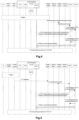
- Fig. 4 is a sequence diagram for describing a first example of a procedure for the fixed broadband access network.
- Fig. 4 illustrates an example of a case in which wideband code-division multiple access (WCDMA) (registered trademark) is used as a communication scheme and corresponds to Figure 9.3.4-1 in 3GPP TS 23.139 V12.2.0.
- WCDMA wideband code-division multiple access
- a target HNB transmits the target HNB local IP address and the UDP port number to a target serving general packet radio service (GPRS) support node (SGSN).
- GPRS general packet radio service
- Step 2a the target SGSN transmits the target HNB local IP address and the UDP port number to a serving gateway (S-GW), and in Step 2b, the S-GW transmits the target HNB local IP address and the UDP port number to a P-GW.
- S-GW serving gateway
- Step 3 the P-GW transmits the target HNB local IP address and the UDP port number to the PCRF.
- Step 4 the PCRF transmits the target HNB local IP address and the UDP port number to the fixed broadband access network.
- Step 2a in Fig. 4 is triggered by the following processes being performed in Step 1.
- Fig. 5 is a sequence diagram for describing another example of the procedure for the fixed broadband access network.
- Fig. 5 illustrates an example of a case that long term evolution (LTE) is used as a communication scheme and corresponds to Figure 9.1.5 in 3GPP TS 23.139 V12.2.0.
- LTE long term evolution
- a target HeNB transmits the target HeNB local IP address and the UDP port number to a MME.
- Step 3 the MME transmits the target HeNB local IP address and the UDP port number to an S-GW, and the S-GW transmits the target HeNB local IP address and the UDP port number to a P-GW.
- Step 4 the P-GW transmits the target HeNB local IP address and the UDP port number to the PCRF.
- Step 5 the PCRF transmits the target HeNB local IP address and the UDP port number to the fixed broadband access network.
- Step 2 in Fig. 5 is triggered by the following processes being performed in Step 1.
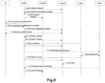
- Fig. 6 is an explanatory diagram for describing a first example of a procedure for handover in a home access network.
- Fig. 6 corresponds to Figure 5.7.2.1-1 in 3GPP TS 25.467 V12.3.0.
- handover of a UE from a source HNB to a target HNB is performed.
- HNB-GW home node B gateway
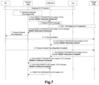
- Fig. 7 is an explanatory diagram for describing a second example of the procedure for handover in a home access network.
- Fig. 7 corresponds to Figure A. 3-1 in 3GPP TS 25.467 V12.3.0.
- handover of a UE from a source HNB to a target HNB is performed.
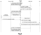
- Fig. 8 is an explanatory diagram for describing an example of a procedure for change of an SeNB.
- Fig. 8 corresponds to Figure 10.1.2.8.4-1 in 3GPP TS 36.300 V13.0.0.
- the SeNB is changed from a source secondary eNB (S-SeNB) to a target secondary eNB (T-SeNB).
- S-SeNB source secondary eNB
- T-SeNB target secondary eNB
- the MeNB transmits an SlAP: E-RAB MODIFICATION INDICATION message to a MME in Step 10.
- the MME makes a request to an S-GW for Bearer Modification.
- the SlAP: E-RAB MODIFICATION INDICATION message includes neither the T-SeNB local IP address nor the UDP port number, the MME is not capable of notifying the S-GW that a SCG bearer has relocated from the S-SeNB to the T-SeNB.
- the PCRF is notified of neither the T-SeNB local IP address nor the UDP port number, and hence control of the fixed broadband access network (e.g., band control) is not performed.
- control of the fixed broadband access network e.g., band control
- maintenance/improvement of communication quality for the 3GPP system users and/or optimization of the capacity of RABs for each base station may be prevented.
- Step 10 is not performed.
- Step 10 maintenance/improvement of communication quality for the 3GPP system users and/or optimization of the capacity of RABs for each base station may be prevented.
- an eNB can configure a hybrid cell.
- a hybrid cell users belonging to a CSG identified with an identifier called CSG ID use the hybrid cell as a CSG cell, and users not belonging to the CSG use the hybrid cell as a normal cell.
- the eNB configuring the hybrid cell may give preference for the users using the hybrid cell as a CSG cell over the users using the hybrid cell as a normal cell, at the time of determining whether or not to accept a UE to be handed over and the time of determining which bearer(s) to accept and which bearer(s) to reject in a case of accepting the UE to be handed over.
- an SeNB configures a hybrid cell.
- an MeNB receives, from a UE, CSG ID notified through the hybrid cell configured by the SeNB and notifies a MME of the CSG ID.
- the MME determines whether the UE uses the hybrid cell configured by the SeNB as a CSG cell or a normal cell.
- 3GPP R3-151949 and 3GPP R3-151995 disclose candidates for a procedure for this determination.
- the MeNB transmits, to the MME, an SlAP: E-RAB MODIFICATION INDICATION message including the CSG ID (CSG ID notified through the hybrid cell configured by the SeNB).
- the MeNB transmits, to the MME, an SlAP: UE CONTEXT MODIFICATION INDICATION message (new message) including the CSG ID.
- the MeNB transmits, to the MME, an SlAP: E-RAB MODIFICATION INDICATION message including the CSG ID (CSG ID notified through the hybrid cell configured by the SeNB) irrespective of whether or not the SCG bearer option is configured.
- the message transmitted from the MeNB to the MME includes neither the local IP address nor the UDP port number of the SeNB.
- band control of the fixed broadband access network is not performed.
- maintenance/improvement of communication quality for the 3GPP system users and/or optimization of the capacity of RABs for each base station may be prevented.
- the PCRF of the 3GPP system transmits, to the fixed broadband access network, the local IP address of the base station (i.e., the outer IP address of the IPsec tunnel, the public IP address, or the global IP address) and the UDP port number received from the P-GW, together with the QoS information in the PCRF.
- the local IP address of the base station i.e., the outer IP address of the IPsec tunnel, the public IP address, or the global IP address
- the UDP port number received from the P-GW together with the QoS information in the PCRF.
- the fixed broadband access network converts the QoS information into the DSCP, applies the DSCP to a line associated with the local IP address and the UDP port number received from the PCRF, and performs control on the band for the 3GPP system users.
- An example object of the example embodiments of the present invention is to enable a core network node to acquire, for example, information necessary for control of a fixed broadband access network in more cases.
- an SeNB is changed from a source SeNB to a target SeNB.
- an MeNB transmits, to an MME, a message including address information (e.g., IP address) and transport identification information (e.g., UDP port number) of the target SeNB.
- address information e.g., IP address
- transport identification information e.g., UDP port number
- the core network node can acquire information necessary for control of the fixed broadband access network in a case with dual connectivity (specifically, a case with change of SeNB).
- a case with change of SeNB a case with change of SeNB
- communication quality for the 3GPP system users may be maintained/improved, and the capacity of RABs for each base station may be adjusted appropriately.
- an HNB communicating with a UE is changed from a source HNB to a target HNB.
- an HNB-GW transmits, to an SGSN core network node, a message including the address information (e.g., IP address) and the transport identification information (e.g., UDP port number) of the target HNB.
- the SGSN receives the message.
- the core network node can acquire information necessary for control of the fixed broadband access network in a case with a home access network (specifically, a case with a handover between HNBs serviced by the same HNB-GW).
- a case with a handover between HNBs serviced by the same HNB-GW can acquire information necessary for control of the fixed broadband access network in a case with a home access network (specifically, a case with a handover between HNBs serviced by the same HNB-GW).
- communication quality for the 3GPP system users may be maintained/improved, and the capacity of RABs for each base station may be adjusted appropriately.
- Fig. 9 is an explanatory diagram illustrating an example of a schematic configuration of the system 1 according to the first example embodiment.
- the system 1 includes a UE 10, an eNB 100, an eNB 200A, an eNB 200B, an MME 300, an S-GW 20, a P-GW 30, a PCRF 40, and a fixed broadband access (FBA) 50.
- FBA fixed broadband access
- the UE 10 can support dual connectivity and communicate with an MeNB and an SeNB.
- the eNB 100 is an eNB capable of operating as the MeNB and the eNB 200 is an eNB capable of operating as the SeNB.
- the eNB 100 is an eNB (macro eNB) for a macro cell
- the eNB 200 is an eNB (small eNB) for a small cell (e.g., a micro cell, a pico cell, a femtocell, or the like).
- the eNB 200 is a home eNB. Note that the eNB 100 and the eNB 200 are not limited to these examples.
- the eNB 100 operates as the MeNB for the UE 10
- the eNB 200A operates as the SeNB for the UE 10
- the UE 10 communicates with the eNB 100 (MeNB) and the eNB 200A (SeNB).
- the SeNB is changed from the eNB 200A (S-SeNB) to the eNB 200B (T-SeNB) due to movement of the UE 10.
- the UE 10 communicates with the eNB 100 (MeNB) and the eNB 200B (SeNB).
- the eNB 100 is connected with each of the eNB 200A and the eNB 200B via an X2 interface.
- An X2 gateway (X2 GW) may be provided between the eNB 100 and the eNB 200.
- each of the eNB 100, the eNB 200A, and the eNB 200B is connected with the MME via an S1 interface.
- the MME 300 is connected with the S-GW 20 via an S11 interface.
- the S-GW 20 is connected with the P-GW 30 via an S5 interface.
- the PCRF is a node configuring a policy to a network, and the PCRF is connected with the P-GW 30 via a Gx interface and with the FBA 50 via an S9a interface.
- Fig. 10 is a block diagram illustrating an example of a schematic configuration of the eNB 100 according to the first example embodiment.
- the eNB 100 includes a wireless communication unit 110, a network communication unit 120, a storage unit 130, and a processing unit 140.
- the wireless communication unit 110 transmits and/or receives a signal wirelessly.
- the wireless communication unit 110 receives a signal from the UE and transmits a signal to the UE.
- the network communication unit 120 receives a signal from a network (e.g., backhaul), and transmits a signal to the network.
- a network e.g., backhaul
- the storage unit 130 temporarily or permanently stores programs and parameters for operations of the eNB 100 as well as various data.
- the processing unit 140 provides various functions of the eNB 100.
- the processing unit 140 includes a first communication processing unit 141, a second communication processing unit 143, and a generation unit 145.
- the processing unit 140 may further include constituent components other than these constituent components. In other words, the processing unit 140 may also perform operations other than the operations of these constituent components.
- the processing unit 140 (first communication processing unit 141) communicates with the UE via the wireless communication unit 110.
- the processing unit 140 (second communication processing unit 143) communicates with another network node(s) (e.g., eNB 200, MME 300, or the like) via the network communication unit 120.
- another network node(s) e.g., eNB 200, MME 300, or the like
- the wireless communication unit 110 may include an antenna, a radio frequency (RF) circuit, and the like.
- the network communication unit 120 may include a network adapter, a network interface card, or the like.
- the storage unit 130 may include a memory (e.g., a nonvolatile memory and/or volatile memory) and/or a hard disk, and the like.
- the processing unit 140 may include a baseband (BB) processor and/or other processors, and the like.
- BB baseband
- the SeNB for the UE 10 i.e., SeNB providing additional radio resources to the UE 10 in dual connectivity
- the eNB 100 (second communication processing unit 143) transmits a first message including the address information and the transport identification information of the eNB 200B (i.e., target SeNB) to a core network node.
- the eNB 100 (generation unit 145) generates the first message.
- the core network node can acquire information necessary for control of the fixed broadband access network in a case with dual connectivity (specifically, a case with change of SeNB).
- a case with change of SeNB a case with change of SeNB
- communication quality for the 3GPP system users may be maintained/improved, and the capacity of RABs for each base station may be adjusted appropriately.
- the core network node is the MME 300.
- the first message includes tunnel information including the address information and the transport identification information.
- the tunnel information is Tunnel Information for BBF IE, for example.
- the Tunnel Information for BBF IE includes an IP address (address information) and a UDP port number (transport identification information).
- the first message is an SlAP: E-RAB MODIFICATION INDICATION message.
- the eNB 100 transmits the SlAP: E-RAB MODIFICATION INDICATION message to the core network node.
- the eNB 100 transmits the SlAP: E-RAB MODIFICATION INDICATION message to the core network node. This enables forwarding of the address information and the transport identification information by using the same message regardless of the presence/absence of the SCG bearer.
- Fig. 11 is an explanatory diagram for describing an example of the SlAP: E-RAB MODIFICATION INDICATION message according to the first example embodiment.
- information elements (IEs) included in the SlAP: E-RAB MODIFICATION INDICATION message are illustrated.
- the SlAP: E-RAB MODIFICATION INDICATION message includes the Tunnel Information for BBF IE including the IP address (address information) and the UDP port number (transport identification information).
- the eNB 100 may transmit other types of message to the core network node.
- the example of the first message transmitted by the eNB 100 has been described, but the first message transmitted by the eNB 100 is, of course, not limited to this example.
- the first message transmitted by the eNB 100 may be other types of message.
- the eNB 100 (generation unit 145) may acquire the first message from another node instead of generating the first message by the eNB 100 itself.
- the eNB 100 receives a second message including the address information and the transport identification information.
- the second message is a message transmitted by the eNB 200. This point is described below in relation to the eNB 200. This enables the eNB 100 to acquire the address information and the transport identification information of the eNB 200, for example.
- the address information is identification information (address) of the network layer (in open system interconnection (OSI) reference model) or the Internet layer (in transmission control protocol/Internet protocol (TCP/IP)).
- the address information is an IP address, for example.
- the IP address is a public IP address (or a global IP address).
- the IP address is a public IP address assigned to the eNB 200B (i.e., target SeNB) by a BBF domain in a no network-address-translation (no-NAT) case, or a public IP address assigned by the BBF domain to a residential gateway (RG) with NAT (i.e., NATed RG), the public IP addresses being used for the eNB 200B.
- the IP address may be called as a "local IP address" in 3GPP specifications.
- the transport identification information is identification information of the transport layer (in OSI reference model or TCP/IP).
- the transport identification information is the UDP port number, for example.
- the address information and the transport identification information are information provided to the FBA 50. More specifically, the address information and the transport identification information are information provided to the FBA 50 from the PCRF 40, for example. With this configuration, bandwidth control may be performed, for example.
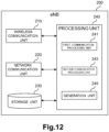
- Fig. 12 is a block diagram illustrating an example of a schematic configuration of the eNB 200 according to the first example embodiment.
- the eNB 200 includes a wireless communication unit 210, a network communication unit 220, a storage unit 230, and a processing unit 240.
- the wireless communication unit 210 transmits and/or receives a signal wirelessly.
- the wireless communication unit 210 receives a signal from the UE and transmits a signal to the UE.
- the network communication unit 220 receives a signal from a network (e.g., backhaul), and transmits a signal to the network.
- a network e.g., backhaul
- the storage unit 230 temporarily or permanently stores programs and parameters for operations of the eNB 200 as well as various data.
- the processing unit 240 provides various functions of the eNB 200.
- the processing unit 240 includes a first communication processing unit 241, a second communication processing unit 243, and a generation unit 245.
- the processing unit 240 may further include constituent components other than these constituent components. In other words, the processing unit 240 may also perform operations other than the operations of these constituent components.
- the processing unit 240 (first communication processing unit 241) communicates with the UE via the wireless communication unit 210.
- the processing unit 240 (second communication processing unit 243) communicates with another network node(s) (e.g., eNB 100, MME 300, or the like) via the network communication unit 220.
- another network node(s) e.g., eNB 100, MME 300, or the like
- the wireless communication unit 210 may include an antenna, a radio frequency (RF) circuit, and the like.
- the network communication unit 220 may include a network adapter, a network interface card, or the like.
- the storage unit 230 may include a memory (e.g., a nonvolatile memory and/or volatile memory) and/or a hard disk, and the like.
- the processing unit 240 may include a baseband (BB) processor and/or other processors, and the like.
- BB baseband
- the eNB 200 can operate as the SeNB (i.e., SeNB providing additional radio resources to the UE 10 in dual connectivity), and the eNB 100 can operate as the MeNB.
- SeNB i.e., SeNB providing additional radio resources to the UE 10 in dual connectivity
- MeNB MeNB
- the eNB 200 (second communication processing unit 243) transmits a message including the address information and the transport identification information of the eNB 200 to a core network node that transfers the address information and the transport identification information to the eNB 100, or the eNB 100.
- the eNB 200 (generation unit 245) generates the above-described message.
- control of the fixed broadband access network may be performed in a case with dual connectivity (specifically, a case with change of SeNB).
- the above-described message includes tunnel information including the address information and the transport identification information.
- the tunnel information is Tunnel Information for BBF IE, for example.
- the Tunnel Information for BBF IE includes the IP address (address information) and the UDP port number (transport identification information).
- the eNB 200 (second communication processing unit 243) transmits the above-described message to the core network node.
- the core network node is the MME 300.
- the message is an SlAP: ENB CONFIGURATION TRANSFER message.
- the core network node MME300 is a node that transmits, to the eNB 100, an SlAP: MME CONFIGURATION TRANSFER message including the address information (IP address) and the transport identification information (UDP port number).
- the SlAP: ENB CONFIGURATION TRANSFER message and the SlAP: MME CONFIGURATION TRANSFER message include a SON Configuration Transfer IE
- the SON Configuration Transfer IE includes an X2 TNL Configuration Info IE.
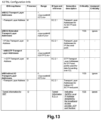
- the X2 TNL Configuration Info IE includes information elements as illustrated in Fig. 13 , and especially includes Tunnel Information for BBF IE.
- the Tunnel Information for BBF IE includes information elements as illustrated in Fig. 14 .
- the Tunnel Information for BBF IE includes a transport layer address and the UDP port number.
- the transport layer address is an IP address.
- the eNB 200 (second communication processing unit 243) transmits the above-described message to the eNB 100.
- the eNB 200 (second communication processing unit 243) may transmit the message to the eNB 100 directly or may transmit the message to the eNB 100 via the X2 GW.
- the message is an X2AP: X2 SETUP REQUEST message or an X2AP: X2 SETUP RESPONSE message.
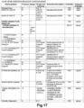
- the X2AP:X2 SETUP REQUEST message includes information elements as illustrated in Fig. 15 , and especially includes the Tunnel Information for BBF IE.
- the Tunnel Information for BBF IE includes information elements as illustrated in Fig. 14 .
- the Tunnel Information for BBF IE includes the transport layer address (i.e., IP address) and the UDP port number.
- the X2AP: X2 SETUP RESPONSE message includes information elements as illustrated in Fig. 16 , and especially includes the Tunnel Information for BBF IE.
- the Tunnel Information for BBF IE includes information elements as illustrated in Fig. 14 .
- the Tunnel Information for BBF IE includes the transport layer address (i.e., IP address) and the UDP port number.
- the eNB 200 may transmit the above-described message to the eNB 100.
- the eNB 200 may transmit the message to the eNB 100 directly, or may transmit the message to the eNB 100 via the X2 gateway (X2 GW).
- the message may be an X2AP: SENB ADDITION REQUEST ACKNOWLEDGE message.
- the eNB 200B (second communication processing unit 243) may transmit the message when the SeNB is changed from the eNB 200A (source SeNB) to the eNB 200B (target SeNB).
- the X2AP: SENB ADDITION REQUEST ACKNOWLEDGE message may include information elements as illustrated in Fig. 17 , and may especially include the Tunnel Information for BBF IE. Furthermore, the Tunnel Information for BBF IE may include information elements as illustrated in Fig. 14 . In other words, the Tunnel Information for BBF IE may include the transport layer address (i.e., IP address) and the UDP port number.
- the examples of the message transmitted by the eNB 200 have been described, but the message transmitted by the eNB 200 is, of course, not limited to these examples.
- the message transmitted by the eNB 200 may be other types of message.
- the address information is an IP address
- the transport identification information is a UDP port number
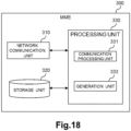
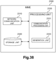
- Fig. 18 is a block diagram illustrating an example of a schematic configuration of the MME 300 according to the first example embodiment.
- the MME 300 includes a network communication unit 310, a storage unit 320, and a processing unit 330.
- the network communication unit 310 receives a signal from a network and transmits a signal to the network.
- the storage unit 320 temporarily or permanently stores programs and parameters for operations of the MME 300 as well as various data.
- the processing unit 330 provides various functions of the MME 300.
- the processing unit 330 includes a communication processing unit 331 and a generation unit 333.
- the processing unit 330 may further include constituent components other than these constituent components. In other words, the processing unit 330 may also perform operations other than the operations of these constituent components.
- the processing unit 330 communicates with each eNB via the network communication unit 310.
- the network communication unit 310 may include a network adapter, a network interface card, or the like.
- the storage unit 320 may include a memory (e.g., a nonvolatile memory and/or volatile memory) and/or a hard disk, and the like.
- the processing unit 330 may include a processor or the like.
- the SeNB for the UE 10 i.e., SeNB providing additional radio resources to the UE 10 in dual connectivity
- the MME 300 receives the first message including the address information and the transport identification information of the eNB 200B (target SeNB) from the eNB 100 (MeNB).
- the MME 300 transmits a second message including the address information and the transport identification information to the core network node.
- the MME 300 generation unit 333
- the core network node can acquire information necessary for control of the fixed broadband access network in a case with dual connectivity (specifically, a case with change of SeNB).
- a case with change of SeNB a case with change of SeNB
- communication quality for the 3GPP system users may be maintained/improved, and the capacity of RABs for each base station may be adjusted appropriately.
- the core network node is the S-GW 20.
- the first message received from the eNB 100 has been described above in relation to the configuration example of the eNB 100.
- the second message transmitted to the core network node is a MODIFY BEARER REQUEST message, for example.
- the second message transmitted by the MME 300 is, of course, not limited to this example.
- the second message transmitted by the MME 300 may be other types of message.
- the address information is an IP address
- the transport identification information is a UDP port number
- FIG. 19 is a sequence diagram illustrating an example of a schematic flow of processing according to the first example embodiment.
- the SeNB for the UE 10 is changed from the eNB 200A (source SeNB) to the eNB 200B (target SeNB). Accordingly, the eNB 100, the eNB 200A, and the eNB 200B are respectively written as an MeNB 100, an S-SeNB 200A, and a T-SeNB 200B, here.
- an X2 link is established between eNBs.
- the X2 link is established between the MeNB 100 and the T-SeNB 200B.
- the X2 link is directly established between the eNBs or is indirectly established via the X2 GW.
- the X2 link can be manually established by an operator.
- the X2 link can be automatically established by self-organization network (SON) specified in Chapter 22 of 3GPP TS 36.300.
- SON is a network automated optimization algorithm.
- both the MeNB 100 and the T-SeNB 200B can initiate the processing for establishing the X2 link, but it is assumed here that the MeNB 100 initiates the processing.
- the X2 link between the MeNB 100 and the S-SeNB 200A and the X2 link between the S-SeNB 200A and the T-SeNB 200B are also established by one of the four techniques described above, but description thereof is omitted here.
- the MeNB 100 transmits an SlAP: ENB CONFIGURATION TRANSFER message defined by 3GPP TS 36.413 V13.0.0 to the MME 300.
- the SlAP: ENB CONFIGURATION TRANSFER message includes a SON Configuration Transfer IE
- the SON Configuration Transfer IE includes an X2 TNL Configuration Info IE (refer to Fig. 13 ).
- the X2 TNL Configuration Info IE includes Tunnel Information for BBF IE (refer to Fig. 14 ).
- the Tunnel Information for BBF IE includes the local IP address (i.e., public IP address, or global IP address) and the UDP port number of the MeNB 100.
- the MME 300 transmits an SlAP: MME CONFIGURATION TRANSFER message to the T-SeNB 200B.
- the SlAP: MME CONFIGURATION TRANSFER message includes the SON Configuration Transfer IE included in the SlAP: ENB CONFIGURATION TRANSFER message.
- the SON Configuration Transfer IE is transmitted to the T-SeNB 200B from the MeNB 100 via the MME 300. This enables the T-SeNB 200B to acquire the local IP address and the UDP port number of the MeNB 100.
- the T-SeNB 200B transmits an SlAP: ENB CONFIGURATION TRANSFER message to the MME 300.
- the SlAP: ENB CONFIGURATION TRANSFER message includes the information element (IE) as described above, and especially includes the local IP address and the UDP port number of the T-SeNB here.
- IE information element
- the MME 300 transmits an SlAP: MME CONFIGURATION TRANSFER message to the MeNB 100.
- the SlAP: MME CONFIGURATION TRANSFER message includes the SON Configuration Transfer IE included in the SlAP: ENB CONFIGURATION TRANSFER message.
- the SON Configuration Transfer IE is transmitted to the MeNB 100B from the T-SeNB 200B via the MME 300. This enables the MeNB 100 to acquire the local IP address and the UDP port number of the T-SeNB 200B.
- the MeNB 100 transmits an X2AP: X2 SETUP REQUEST message (refer to Fig. 15 ) defined by 3GPP TS 36.423 V13.0.0 to the T-SeNB 200B, on the basis of the configuration by an operator (e.g., configuration of the local IP address and the UDP port number of the T-SeNB 200B (as a destination)).
- the X2AP: X2 SETUP REQUEST message includes the local IP address and the UDP port number of the MeNB. This enables the T-SeNB 200B to acquire the local IP address and the UDP port number of the MeNB 100.
- the T-SeNB 200B transmits an X2AP: X2 SETUP RESPONSE message (refer to Fig. 16 ) defined by 3GPP TS 36.423 V13.0.0 to the MeNB 100.
- the X2AP: X2 SETUP RESPONSE message includes the local IP address and the UDP port number of the T-SeNB 200B. This enables the MeNB 100 to acquire the local IP address and the UDP port number of the T-SeNB 200B.
- the T-SeNB 200B may transmit the X2AP: X2 SETUP REQUEST message (refer to Fig. 15 ) to the MeNB 100, and the MeNB 100 may transmit the X2AP: X2 SETUP RESPONSE message (refer to Fig. 16 ) to the T-SeNB 200B.
- Step S401C is the same as step S401A except for processing for the X2AP messages between the MeNB 100 and the X2 GW, and processing for the X2AP messages between the X2 GW and the T-SeNB 200B (i.e., processing added to the procedure in Chapter 22.3.6.1 of 3GPP TS 36.300 V13.0.0). Hence, overlapping descriptions are omitted here.
- the MeNB 100 transmits an X2AP: X2AP MESSAGE TRANSFER message defined by 3GPP TS 36.423 V13.0.0 to the X2 GW (T-SeNB 200B).
- the X2AP MESSAGE TRANSFER message includes the X2AP: X2 SETUP REQUEST message (refer to Fig. 15 ).
- the MeNB 100 transmits the X2AP: X2 SETUP REQUEST message to the T-SeNB 200B via the X2 GW.
- the X2AP: X2 SETUP REQUEST message includes the local IP address and the UDP port number of the MeNB 100. This enables the T-SeNB 200B to acquire the local IP address and the UDP port number of the MeNB 100.
- the T-SeNB 200B transmits an X2AP: X2AP MESSAGE TRANSFER message defined by 3GPP TS 36.423 V13.0.0 to the X2 GW (MeNB 100).
- the X2AP MESSAGE TRANSFER message includes the X2AP: X2 SETUP RESPONSE message (refer to Fig. 16 ).
- the T-SeNB 200B transmits the X2AP: X2 SETUP RESPONSE message to the MeNB 100 via the X2 GW.
- the X2AP: X2 SETUP RESPONSE message includes the local IP address and the UDP port number of the T-SeNB 200B. This enables the MeNB 100 to acquire the local IP address and the UDP port number of the T-SeNB 200B.
- the T-SeNB 200B may transmit the X2AP: X2 SETUP REQUEST message (refer to Fig. 15 ) to the MeNB 100, and the MeNB 100 may transmit the X2AP: X2 SETUP RESPONSE message (refer to Fig. 16 ) to the T-SeNB 200B.
- Dual connectivity for the UE 10 is initiated at arbitrary timing after completion of step S401. More specifically, the UE 10 initiates communication with both the MeNB 100 and the S-SeNB 200A.
- the MeNB 100 transmits an X2AP: SENB ADDITION REQUEST message to the T-SeNB 200B. With this operation, the MeNB 100 requests the T-SeNB 200B to allocate resources for the UE 10.
- the T-SeNB 200B transmits an X2AP: SENB ADDITION REQUEST ACKNOWLEDGE message to the MeNB 100. With this operation, the T-SeNB 200B notifies the MeNB 100 that the resources have been allocated for the UE 10.
- the X2AP: SENB ADDITION REQUEST ACKNOWLEDGE message may include information elements as illustrated in Fig. 17 , and may especially include the Tunnel Information for BBF IE. Furthermore, the Tunnel Information for BBF IE may include information elements as illustrated in Fig. 14 .
- the MeNB 100 transmits an X2AP: SENB RELEASE REQUEST message to the S-SeNB 200A. With this operation, the S-SeNB 200A releases resources for the UE 10.
- the MeNB 100 instructs the UE 10 to apply a new configuration.
- the UE 10 notifies the MeNB 100 that the new configuration has been applied.
- the MeNB 100 transmits an X2AP: SENB RECONFIGURATION COMPLETE message to the T-SeNB 200B. With this operation, the MeNB 100 notifies the T-SeNB 200B that an RRC connection reconfiguration procedure has been completed successfully.
- the UE 10 performs synchronisation towards the T-SeNB 200B.
- Data is transferred to the T-SeNB 200B from the S-SeNB 200A.
- the MeNB 100 transmits an SlAP: E-RAB MODIFICATION INDICATION message (refer to Fig. 11 ) to the MME 300.
- the SlAP: E-RAB MODIFICATION INDICATION message includes Tunnel Information for BBF IE. Furthermore, the Tunnel Information for BBF IE includes the local IP address and the UDP port number of the T-SeNB 200B.
- the MeNB 100 When there is no SCG bearer for the UE 10 and the S-SeNB 200A and there is only a split bearer (i.e., when a SCG bearer option is not configured), the MeNB 100 does not transmit the SlAP: E-RAB MODIFICATION INDICATION message to the MME 300 according to 3GPP TS 36.300 v13.0.0. However, in the first example embodiment, the MeNB 100 transmits the SlAP: E-RAB MODIFICATION INDICATION message to the MME 300, for example.
- the SlAP: E-RAB MODIFICATION INDICATION message includes Tunnel Information for BBF IE. Furthermore, the Tunnel Information for BBF IE includes the local IP address and the UDP port number of the T-SeNB 200B.
- the MME 100 transmits a MODIFY BEARER REQUEST message to the S-GW 20.
- the S-GW 20 updates a data path when there is the SCG bearer, and the S-GW 20 does not update the data path when there is no SCG bearer (i.e., when there is only a split bearer).
- the S-GW 20 transmits a Modify Bearer Request message (including the local IP address and the UDP port number of the T-SeNB 200B) to the P-GW 30.
- the P-GW30 transmits an IP-CAN session modification request message (including the local IP address and the UDP port number of the T-SeNB 200B) to the PCRF 40.
- the PCRF 40 performs, with the FBA 50, a Gateway control and QoS Rule provisioning procedure (including transmission and reception of the local IP address and the UDP port number of the T-SeNB 200B).
- the FBA 50 applies the QoS information converted into DSCP to a line associated with the local IP address and the UDP port number of the T-SeNB 200B, the local IP address and the UDP port number being received from the PCRF 40.
- the FBA 50 performs bandwidth control on the line connected with the T-SeNB 200B.
- the upper limit value of the band (band 93) that is secured for the base station used by a user of a 3GPP system may be adjusted as illustrated in Fig. 1 .
- a band (band 95) capable of newly accepting a 3GPP system user(s) may be reduced as illustrated in Fig. 2 .
- the PCRF 40 transmits an IP-CAN session modification Acknowledge message to the P-GW 30.
- the P-GW 30 transmits Modify Bearer Response to the S-GW 20.
- the S-GW 20 transmits a Modify Bearer Response message to the MME 300.
- the MME 300 transmits an SlAP: E-RAB MODIFICATION CONFIRM message to the MeNB 100.
- the MeNB 100 transmits an X2AP: UE CONTEXT RELEASE message to the S-SeNB 200A. With this operation, the S-SeNB 200A releases a UE context.
- step S447 is performed after step S445, but step S447 may be performed at arbitrary timing after step S433.
- the X2AP SETUP REQUEST message
- the X2AP: X2 SETUP RESPONSE message the X2AP: SENB ADDITION REQUEST ACKNOWLEDGE message
- the SlAP: ENB CONFIGURATION TRANSFER message the SlAP: MME CONFIGURATION TRANSFER message
- the SlAP: E-RAB MODIFICATION INDICATION message which include the Tunnel Information for BBF IE as a new information element.
- these messages are only exemplifications, and other messages including the IP address and the UDP port number (e.g., Tunnel Information for BBF IE) may be used.
- Each network node may not be constituted by individual hardware, but may operate on a virtual machine as a virtualized network function (VNF).
- VNF virtualized network function
- NFV network function virtualization
- the network node which operates on the virtual machine as VFN may be managed and arranged by a function called management and orchestration (MANO).
- MANO management and orchestration
- MANO which manages the VNF of each network node (e.g., eNB 100, eNB 200, MME 300, S-GW 20, P-GW 30, and/or PCRF 40) of a cellular network also manages a software-defined network (SDN) controller which is a constituent element of the FBA 50.
- SDN software-defined network
- bandwidth control of the FBA 50 may be performed by the MANO, instead of the PCRF 50 that is the VFN.
- the function corresponding to the PCRF 40 may be provided in a radio access network (RAN).
- the RAN may control (e.g., perform bandwidth control of) a fixed broadband access network (FBA 50).
- FBA 50 fixed broadband access network
- the eNB 100 may transmit the above-described first message to the node having the above-described functions instead of the MME 300.
- the MME 300 may transmit the above-described second message to the node having the above-described functions instead of the S-GW 20.
- LTE-wireless local area network (LTE-WLAN) aggregation LWA
- LTE-WLAN LTE-wireless local area network
- the UE communicates using both LTE and WLAN.
- an MCG bearer on which data is transmitted only by LTE a split bearer on which data is transmitted by both LTE and WLAN, and a switched bearer on which data is transmitted only by WLAN are provided.
- the eNB transmits data via an Xw interface to the WLAN.
- the technique that is the same as or similar to the above-described example (i.e., the example of dual connectivity) in the first example embodiment may be applied also to the LWA case.
- communication quality for the 3GPP system users may be maintained/improved, and/or the capacity of UEs for each base station may be adjusted appropriately.
- Fig. 20 is an explanatory diagram illustrating an example of a schematic configuration of a system according to a third modified example of the first example embodiment.
- the system includes the eNB 100, a WLAN Termination (WT) 201A, a WT 201B, a WLAN AP 203A, a WLAN AP 203B, and the MME 300.
- the system further includes the UE 10, the S-GW 20, the P-GW 30, the PCRF 40, and the FBA 50.
- each of the WT 201A and the WT 201B may be simply referred to as a WT 201.
- each of the WLAN AP 203A and the WLAN AP 203B may be simply referred to as a WLAN AP 203.
- the WT 201 terminates an Xw interface.
- the WLAN AP 203 belongs to a WLAN mobility set (i.e., set of one or more WLAN APs).
- the WLAN mobility set shares the common WT 201.
- the WLAN AP 203A belongs to a first WLAN mobility set, and the first WLAN mobility set shares the WT 201A.
- the WLAN AP 203B belongs to a second WLAN mobility set, and the second WLAN mobility set shares the WT 201B.
- the UE 10 supports LWA, and can communicate with the eNB 100 and the WLAN AP 203. Particularly in this example, first, the UE 10 is in communication with the eNB 100 and the WLAN AP 203A by LWA. After that, for example, the AP with which the UE 10 communicates is changed from the WLAN AP 203A (S-AP) to the WLAN AP 203B (T-AP) due to movement of the UE 10. As a result, the UE 10 communicates with the eNB 100 and the WLAN AP 203B.
- S-AP WLAN AP 203A
- T-AP WLAN AP 203B
- the WLAN AP i.e., WLAN AP of LTE-WLAN aggregation
- the eNB 100 transmits a first message including address information and transport identification information of the WLAN AP 203B to the core network node (e.g., MME 300).
- the eNB 100 generation unit 145) generates the first message.
- the MME 300 receives the first message from the eNB 100.
- the MME 300 transmits a second message including the address information and the transport identification information to the core network node (e.g., S-GW 20).
- the MME 300 generation unit 333
- the WLAN AP 203B (communication processing unit) transmits a third message including address information and transport identification information of the WLAN AP 203B to the eNB 100 (e.g., via WT 201B).
- the WLAN AP 203B (generation unit) generates the third message.
- the WT 201B (communication processing unit) may transmit the third message including the address information and the transport identification information of the WLAN AP 203B to the eNB 100.
- the WT 201B (generation unit) may generate the third message.
- the core network node can acquire information necessary for control of the fixed broadband access network in a case with LTE-WLAN aggregation (specifically, a case with change of WLAN AP).
- LTE-WLAN aggregation specifically, a case with change of WLAN AP.
- communication quality for the 3GPP system users may be maintained/improved, and the capacity of RABs for each base station may be adjusted appropriately.
- Fig. 21 is an explanatory diagram illustrating an example of a schematic configuration of the system 2 according to the second example embodiment.
- the system 2 includes a terminal apparatus 11, a base station 500, a wireless communication apparatus 600A, a wireless communication apparatus 600B, a first core network node 700, and a second core network node 60.
- each of the wireless communication apparatus 600A and the wireless communication apparatus 600B may be simply referred to as a wireless communication apparatus 600.
- the terminal apparatus 11 is a UE
- the base station 500 is an eNB
- the first core network node 700 is an MME
- the second core network node 60 is an S-GW.
- the terminal apparatus 11 can communicate with the base station 500 and the wireless communication apparatus 600.
- the wireless communication apparatus 600 can communicate with the terminal apparatus 11 communicating with the base station 500.
- the wireless communication apparatus communicating with the terminal apparatus 11 which communicates with the base station 500 may be changed from the wireless communication apparatus 600A to the wireless communication apparatus 600B due to movement of the terminal apparatus 11.
- the terminal apparatus 11 supports dual connectivity.
- the wireless communication apparatus 600 is a base station capable of operating as a secondary base station which provides additional radio resources to the terminal apparatus 11 in dual connectivity.
- the wireless communication apparatus 600 is an eNB capable of operating as an SeNB.
- the wireless communication apparatus 600 is a home eNB, but is not limited to this example.
- the base station 500 can operate as a master base station associated with the secondary base station.
- the base station 500 is an eNB capable of operating as an MeNB.
- the secondary base station for the terminal apparatus 11 may be changed from the wireless communication apparatus 600A to the wireless communication apparatus 600B due to movement of the terminal apparatus 11.
- the terminal apparatus 11 may support aggregation of radio access technologies different from each other.
- the aggregation may be LTE-WLAN aggregation (LWA).
- the wireless communication apparatus 600 may be an access point (AP) using a radio access technology different from a radio access technology in the base station 500.
- the wireless communication apparatus 600 may be a WLAN AP.
- the wireless communication apparatus 600 may communicate with the base station 500 via a WLAN Termination (WT).
- WT WLAN Termination
- the wireless communication apparatus 600A may be a first AP belonging to a first mobility set, and the wireless communication apparatus 600B may be a second AP belonging to a second mobility set which is different from the first mobility set.
- the first mobility set may share a first WT
- the second mobility set may share a second WT.
- the AP communicating with the terminal apparatus 11 which communicates with the base station 500 may be changed from the wireless communication apparatus 600A to the wireless communication apparatus 600B due to movement of the terminal apparatus 11.
- FIG. 22 is a block diagram illustrating an example of a schematic configuration of the base station 500 according to the second example embodiment.
- the base station 500 includes a communication processing unit 503.
- the communication processing unit 503 may be implemented by a processor and the like.
- the wireless communication apparatus communicating with the terminal apparatus 11 which communicates with the base station 500 is changed from the wireless communication apparatus 600A to the wireless communication apparatus 600B.
- the base station 500 (communication processing unit 503) transmits a first message including address information and transport identification information of the wireless communication apparatus 600B to the first core network node 700.
- the core network node can acquire information necessary for control of the fixed broadband access network in more cases.
- communication quality for the 3GPP system users may be maintained/improved, and the capacity of RABs for each base station may be adjusted appropriately in more cases.
- the wireless communication apparatus 600 is a base station capable of operating as the secondary base station (e.g., SeNB) which provides additional radio resources to the terminal apparatus 11 in dual connectivity, and the base station 500 can operate as the master base station (e.g., MeNB) associated with the secondary base station.
- the secondary base station e.g., SeNB
- MeNB master base station
- Control of the fixed broadband access network may be performed in such a case with dual connectivity (specifically, a case with change of secondary base station).
- dual connectivity specifically, a case with change of secondary base station.
- communication quality for the 3GPP system users may be maintained/improved, and the capacity of RABs for each base station may be adjusted appropriately.
- the wireless communication apparatus 600 may be an AP (e.g., WLAN AP) using a radio access technology different from a radio access technology in the base station 500.
- AP e.g., WLAN AP
- Control of the fixed broadband access network may be performed in such a case with aggregation of radio access technologies different from each other (e.g., LTE-WLAN aggregation) (e.g., a case with change of WLAN AP).
- LTE-WLAN aggregation e.g., a case with change of WLAN AP.
- FIG. 23 is a block diagram illustrating an example of a schematic configuration of the wireless communication apparatus 600 according to the second example embodiment.
- the wireless communication apparatus 600 includes a communication processing unit 603.
- the communication processing unit 603 may be implemented by a processor and the like.
- the wireless communication apparatus 600 (communication processing unit 603) transmits a message including address information and transport identification information of the wireless communication apparatus 600, for example, to the base station 500.
- the wireless communication apparatus 600 (communication processing unit 603) may transmit the message to the core network node (e.g., first core network node 700) which transfers the address information and the transport identification information to the base station 500.
- the core network node e.g., first core network node 700
- the wireless communication apparatus 600 is a base station capable of operating as the secondary base station (e.g., SeNB) which provides additional radio resources to the terminal apparatus 11 in dual connectivity, and the base station 500 can operate as the master base station (e.g., MeNB) associated with the secondary base station.
- the secondary base station e.g., SeNB
- MeNB master base station
- the wireless communication apparatus 600 may be an AP (e.g., WLAN AP) using a radio access technology different from a radio access technology in the base station 500.
- AP e.g., WLAN AP
- FIG. 24 is a block diagram illustrating an example of a schematic configuration of the first core network node 700 according to the second example embodiment.
- the first core network node 700 includes a communication processing unit 701.
- the communication processing unit 701 may be implemented by a processor and the like.
- the wireless communication apparatus communicating with the terminal apparatus 11 which communicates with the base station 500 is changed from the wireless communication apparatus 600A to the wireless communication apparatus 600B.
- the first core network node 700 receives the first message including the address information and the transport identification information of the wireless communication apparatus 600B from the base station 500.
- the first core network node 700 transmits a second message including the address information and the transport identification information to the second core network node 60.
- the core network node can acquire information necessary for control of the fixed broadband access network in more cases.
- communication quality for the 3GPP system users may be maintained/improved, and the capacity of RABs for each base station may be adjusted appropriately in more cases.
- the wireless communication apparatus 600 is a base station capable of operating as the secondary base station (e.g., SeNB) which provides additional radio resources to the terminal apparatus 11 in dual connectivity, and the base station 500 can operate as the master base station (e.g., MeNB) associated with the secondary base station.
- the secondary base station e.g., SeNB
- MeNB master base station
- Control of the fixed broadband access network may be performed in such a case with dual connectivity (specifically, a case with change of secondary base station).
- dual connectivity specifically, a case with change of secondary base station.
- communication quality for the 3GPP system users may be maintained/improved, and the capacity of RABs for each base station may be adjusted appropriately.
- the wireless communication apparatus 600 may be an AP (e.g., WLAN AP) using a radio access technology different from a radio access technology in the base station 500.
- AP e.g., WLAN AP
- Control of the fixed broadband access network may be performed in such a case with aggregation of radio access technologies different from each other (e.g., LTE-WLAN aggregation) (specifically, a case with change of access point).
- LTE-WLAN aggregation e.g., LTE-WLAN aggregation
- control of the fixed broadband access network may be performed in such a case with aggregation of radio access technologies different from each other (e.g., LTE-WLAN aggregation) (specifically, a case with change of access point).
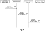
- FIG. 25 is a sequence diagram illustrating an example of a schematic flow of processing according to the second example embodiment.
- the wireless communication apparatus 600 transmits a message including the address information and the transport identification information of the wireless communication apparatus 600 to the base station 500.
- the wireless communication apparatus communicating with the terminal apparatus 11 which communicates with the base station 500 is changed from the wireless communication apparatus 600A to the wireless communication apparatus 600B.
- the base station 500 transmits the first message including the address information and the transport identification information of the wireless communication apparatus 600B to the first core network node 700.
- the first core network node 700 receives the first message from the base station 500.
- the first core network node 700 transmits the second message including the address information and the transport identification information to the second core network node 60.
- the wireless communication apparatus 600 (e.g., WLAN AP) transmits the message including the address information and the transport identification information of the wireless communication apparatus 600 to the base station 500 in the second case.
- a terminating apparatus e.g., WT
- WT wireless communication apparatus
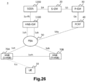
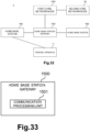
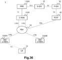
- Fig. 26 is an explanatory diagram illustrating an example of a schematic configuration of the system 3 according to the third example embodiment.
- the system 3 includes a UE 10, an HNB 70A, an HNB 70B, an HNB-GW 1100, an SGSN 1200, an S-GW 20, a P-GW 30, a PCRF 40, and an FBA 50.
- HNB 70A and HNB 70B each of the HNB 70A and the HNB 70B may be simply referred to as an HNB 70.
- the UE 10 communicates with the SGSN 1200 via the HNB 70 and the HNB-GW 1100.
- the UE 10 is in communication with the HNB 70A.
- the HNB communicating with the UE 10 is changed from the HNB 70A (Serving Home Node B (S-HNB)) to the HNB 70B (Target Home Node B (T-HNB)) due to movement of the UE 10.
- S-HNB Serving Home Node B
- T-HNB Target Home Node B
- a handover of the UE 10 from the HNB 70A to the HNB 70B is performed.
- the HNB 70 is connected with the HNB-GW 1100 through the FBA 50.
- the HNB 70 is connected with the HNB-GW 1100 via an Iuh interface.
- the HNB 70 is serviced by the HNB-GW 1100.
- the HNB 70A and the HNB 70B are connected to each other via an Iurh interface, and directly communicate with each other via the Iurh interface when performing the handover (as illustrated in Fig. 6 and Fig. 7 , for example).
- the Iurh interface may not be provided, and the HNB 70A and the HNB 70B may indirectly communicate with each other via the HNB-GW 1100 when performing the handover (as illustrated in Fig. 6 and Fig. 7 , for example).
- the HNB-GW 1100 is connected with the SGSN 1200 via an Iu-PS interface.
- the SGSN 1200 is connected with the S-GW 20 via an S4 interface.
- the S-GW 20 is connected with the P-GW 30 via an S5 interface.
- the PCRF is a node configuring a policy to a network, and the PCRF is connected with the P-GW 30 via a Gx interface and with the FBA 50 via an S9a interface.
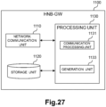
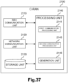
- Fig. 27 is a block diagram illustrating an example of a schematic configuration of the HNB-GW 1100 according to the third example embodiment.
- the HNB-GW 1100 includes a network communication unit 1110, a storage unit 1120, and a processing unit 1130.
- the network communication unit 1110 receives a signal from a network and transmits a signal to the network.
- the storage unit 1120 temporarily or permanently stores programs and parameters for operations of the HNB-GW 1100 as well as various data.
- the processing unit 1130 provides various functions of the HNB-GW 1100.
- the processing unit 1130 includes a communication processing unit 1131 and a generation unit 1133.
- the processing unit 1130 may further include constituent components other than these constituent components. In other words, the processing unit 1130 may also perform operations other than the operations of these constituent components.
- the processing unit 1130 communicates with another network node(s) (e.g., HNB 70, SGSN 1200, and the like) via the network communication unit 1110.
- another network node(s) e.g., HNB 70, SGSN 1200, and the like
- the network communication unit 1110 may include a network adapter, a network interface card, or the like.
- the storage unit 1120 may include a memory (e.g., a nonvolatile memory and/or volatile memory) and/or a hard disk, and the like.
- the processing unit 1130 may include a processor or the like.
- the HNB communicating with the UE 10 is changed from the HNB 70A to the HNB 70B.
- the HNB-GW 1100 (communication processing unit 1131) transmits a message including address information and transport identification information of the HNB 70B to a core network node.
- the HNB-GW 1100 (generation unit 1133) generates the above-described message.
- the core network node can acquire information necessary for control of the fixed broadband access network in a case with a home access network (specifically, a case with a handover between HNBs serviced by the same HNB-GW).
- a case with a handover between HNBs serviced by the same HNB-GW can acquire information necessary for control of the fixed broadband access network in a case with a home access network (specifically, a case with a handover between HNBs serviced by the same HNB-GW).
- communication quality for the 3GPP system users may be maintained/improved, and the capacity of RABs for each base station may be adjusted appropriately.
- the core network node is the SGSN 1200.
- the above-described message includes tunnel information including the address information and the transport identification information.
- the tunnel information is Tunnel Information for BBF IE, for example.
- the Tunnel Information for BBF IE includes the IP address (address information) and the UDP port number (transport identification information).
- the above-described message is a RANAP: RELOCATION COMPLETE message.
- Fig. 28 is an explanatory diagram for describing an example of the RANAP: RELOCATION COMPLETE message according to the third example embodiment.
- information elements (IEs) included in the RANAP: RELOCATION COMPLETE message are illustrated.
- the RANAP: RELOCATION COMPLETE message includes Tunnel Information for BBF IE including the IP address (address information) and the UDP port number (transport identification information).
- the HNB-GW 1100 (generation unit 1133) may acquire the message from another node (e.g., HNB 70 or the like), instead of generating the message by the HNB-GW 1100 itself.
- another node e.g., HNB 70 or the like
- the address information is identification information (address) of the network layer (in OSI reference model) or the Internet layer (in TCP/IP).
- the above-described address information is an IP address, for example.
- the IP address is a public IP address (or a global IP address).
- the IP address is a public IP address assigned to the HNB 70B (i.e., target HNB) by a BBF domain in a no-NAT case, or a public IP address assigned by the BBF domain to the RG with NAT (i.e., NATed RG), the public IP address being used for the HNB 70B.
- the IP address may be called as a "local IP address" or an "H(e)NB local IP address" in 3GPP specifications.
- the transport identification information is identification information of the transport layer (in OSI reference model or TCP/IP).
- the transport identification information is the UDP port number, for example.
- the address information and the transport identification information are information provided to the FBA 50. More specifically, the address information and the transport identification information are information provided to the FBA 50 from the PCRF 40, for example. With this configuration, bandwidth control may be performed, for example.
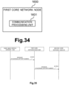
- Fig. 29 is a block diagram illustrating an example of a schematic configuration of the SGSN 1200 according to the third example embodiment.
- the SGSN 1200 includes a network communication unit 1210, a storage unit 1220, and a processing unit 1230.
- the network communication unit 1210 receives a signal from a network and transmits a signal to the network.
- the storage unit 1220 temporarily or permanently stores programs and parameters for operations of the SGSN 1200 as well as various data.
- the processing unit 1230 provides various functions of the SGSN 1200.
- the processing unit 1230 includes a communication processing unit 1231 and a generation unit 1233. Note that the processing unit 1230 may further include constituent components other than these constituent components. In other words, the processing unit 1230 may also perform operations other than the operations of these constituent components.
- the processing unit 1230 communicates with another network node(s) (e.g., HNB-GW 1100, S-GW 20, and the like) via the network communication unit 1210.
- another network node(s) e.g., HNB-GW 1100, S-GW 20, and the like
- the network communication unit 1210 may include a network adapter, a network interface card, or the like.
- the storage unit 1220 may include a memory (e.g., a nonvolatile memory and/or volatile memory) and/or a hard disk, and the like.
- the processing unit 1230 may include a processor or the like.
- the HNB communicating with the UE 10 is changed from the HNB 70A to the HNB 70B.
- a handover of the UE 10 from the HNB 70A to the HNB 70B is performed.
- the SGSN 1200 receives the first message including the address information and the transport identification information of the HNB 70B from the HNB-GW 1100.
- the SGSN 1200 transmits a second message including the address information and the transport identification information to the core network node.
- the SGSN 1200 (generation unit 1233) generates the second message.
- the core network node can acquire information necessary for control of the fixed broadband access network in a case with a home access network (specifically, a case with a handover between HNBs serviced by the same HNB-GW).
- a case with a handover between HNBs serviced by the same HNB-GW can acquire information necessary for control of the fixed broadband access network in a case with a home access network (specifically, a case with a handover between HNBs serviced by the same HNB-GW).
- communication quality for the 3GPP system users may be maintained/improved, and the capacity of RABs for each base station may be adjusted appropriately.
- the core network node is the S-GW 20.
- the first message received from the HNB-GW 1100 has been described above in relation to the configuration example of the HNB-GW 1100.
- the second message transmitted to the core network node is a MODIFY BEARER REQUEST message, for example.
- the address information is an IP address
- the transport identification information is a UDP port number
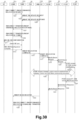
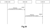
- Fig. 30 is a sequence diagram illustrating a first example of a schematic flow of processing according to the third example embodiment.
- the first example is an example of a case in which an Iurh interface is provided between the HNB 70A and the HNB 70B.
- the UE 10 is in communication with the HNB 70A, and the HNB communicating with the UE 10 is changed from the HNB 70A to the HNB 70B.
- a handover of the UE 10 from the HNB 70A to the HNB 70B is performed.
- the HNB 70A and the HNB 70B are respectively written as an S-HNB 70A and a T-HNB 70B, here. Note that it is assumed that RAB release does not occur after the handover.
- the S-HNB 70A checks (or evaluates) access rights of the UE 10.
- the S-HNB 70A transmits an RNA: CONNECT message (including an RNSAP: ENHANCED RELOCATION REQUEST message) to the T-HNB 70B.
- the T-HNB 70B transmits an HNBAP: TNL UPDATE REQUEST message to the HNB-GW 1100. With this operation, transport network layer information for any RABs that are to be relocated from the S-HNB 70A to the T-HNB 70B is updated.
- the HNB-GW 1100 transmits an HNBAP: TNL UPDATE RESPONSE message to the T-HNB 70B.
- the T-HNB 70B transmits an RNA: DIRECT TRANSFER message (including an RNSAP: ENHANCED RELOCATION RESPONSE message) to the S-HNB 70A. With this operation, the T-HNB 70B notifies the S-HNB 70A that preparation of the handover of the UE 10 is completed.
- the S-HNB 70A transmits an RNA: DIRECT TRANSFER message (including an RNSAP: RELOCATION COMMIT message). This causes the handover of the UE 10 to the T-HNB 70B to be performed.
- the UE 10 performs synchronisation towards the T-HNB 70B in Layer 1.
- the UE 10 transmits an RRC: RADIO BEARER RECONFIGURATION COMPLETE message to the T-HNB 70B. With these operations, an RRC Reconfiguration procedure is terminated.
- the T-HNB 70B transmits an HNBAP: RELOCATION COMPLETE message to the HNB-GW 1100. With this operation, the T-HNB 70B notifies the HNB-GW 1100 that the handover of the UE 10 is successfully performed. The HNB-GW 1100 switches U-plane to the T-HNB 70B.
- the HNB-GW 1100 receives the HNBAP: RELOCATION COMPLETE message from the T-HNB 70B, thereby acquiring that the handover of the UE 10 from the S-HNB 70A to the T-HNB 70B is performed.
- the HNB-GW 1100 transmits a RANAP: RELOCATION COMPLETE message (refer to Fig. 28 ) to the SGSN 1200.
- the RANAP: RELOCATION COMPLETE message includes Tunnel Information for BBF IE. Furthermore, the Tunnel Information for BBF IE includes the local IP address and the UDP port number of the T-HNB 70B.
- the SGSN transmits a RANAP: RELOCATION COMMAND message to the S-HNB (i.e., instructs the S-HNB to perform a handover), and after that, receives a RANAP: RELOCATION COMPLETE message from the T-HNB 70B.
- the RANAP: RELOCATION COMPLETE message is transmitted and received in such a series of processing.
- the HNB-GW 1100 transmits the RANAP: RELOCATION COMPLETE message to the SGSN 1200 without preceding processing, for the notification of the local IP address and the UDP port number of the T-HNB 70B.
- the RANAP: RELOCATION COMPLETE message is only an example, and other types of message (e.g., other types of RANAP message) including the local IP address and the UDP port number of the T-HNB 70B may be transmitted.
- the SGSN 1200 receives the RANAP: RELOCATION COMPLETE message (refer to Fig. 28 ) from the T-HNB 70B, thereby acquiring that the handover of the UE 10 from the S-HNB 70A to the T-HNB 70B is performed. Moreover, the SGSN 1200 acquires the local IP address and the UDP port number of the T-HNB 70B which are included in the RANAP: RELOCATION COMPLETE message. The SGSN 1200 transmits a Modify Bearer Request message including the IP address and the UDP port number to the S-GW 20.
- the SGSN transmits a RANAP: RELOCATION COMMAND message to the S-HNB (i.e., instructs the S-HNB to perform a handover), and after that, receives a RANAP: RELOCATION COMPLETE message from the T-HNB 70B.
- the SGSN 1200 receives the RANAP: RELOCATION COMPLETE message without transmitting the RANAP: RELOCATION COMMAND message, and transmits the Modify Bearer Request message.
- the S-GW 20 transmits the Modify Bearer Request message (including the local IP address and the UDP port number of the T-HNB 70B) to the P-GW 30.
- the P-GW30 transmits an IP-CAN session modification request message (including the local IP address and the UDP port number of the T-HNB 70B) to the PCRF 40.
- the PCRF 40 performs, with the FBA 50, a Gateway control and QoS Rule provisioning procedure (including transmission and reception of the local IP address and the UDP port number of the T-SeNB 200B).
- the FBA 50 applies the QoS information converted into DSCP to a line associated with the local IP address and the UDP port number of the T-SeNB 200B, the local IP address and the UDP port number being received from the PCRF 40.
- the FBA 50 performs bandwidth control on the line connected with the T-SeNB 200B.
- the upper limit value of the band (band 93) that is secured for the base station used by a user of a 3GPP system may be adjusted as illustrated in Fig. 1 .
- a band (band 95) capable of newly accepting a 3GPP system user(s) may be reduced as illustrated in Fig. 2 .
- the PCRF 40 transmits an IP-CAN session modification Acknowledge message to the P-GW 30.
- the P-GW 30 transmits Modify Bearer Response to the S-GW 20.
- the S-GW 20 transmits a Modify Bearer Response message to the SGSN 1200.
- the HNB-GW 1100 transmits an HNBAP: UE-DEREGISTER message to the S-HNB 70A. With this operation, the HNB-GW 1100 notifies the S-HNB 70A of success of the handover.
- the S-HNB 70A transmits an RNA: DISCONNECT message (including an RNSAP: ENHANCED RELOCATION SIGNALLING TRANSFER message) to the T-HNB 70B.
- step S1333 is performed after step S1331, but step S1333 may be performed at arbitrary timing after step S1315.
- Fig. 31 is a sequence diagram illustrating a second example of a schematic flow of processing according to the third example embodiment.
- the second example is an example of a case in which no Iurh interface is provided between the HNB 70A and the HNB 70B.
- the UE 10 is in communication with the HNB 70A, and the HNB communicating with the UE 10 is changed from the HNB 70A to the HNB 70B.
- a handover of the UE 10 from the HNB 70A to the HNB 70B is performed.
- the HNB 70A and the HNB 70B are respectively written as an S-HNB 70A and a T-HNB 70B, here. Note that it is assumed that RAB release does not occur after the handover.
- the UE 10 has established an active packet switched (PS) session to the SGSN 1200 via the S-HNB 70A and the HNB-GW 1100.
- PS packet switched
- the S-HNB 70A makes a decision to relocate the session of the UE 10 to the T-HNB 70B.
- the S-HNB 70A transmits an RNA: DIRECT TRANSFER message (including a RANAP: RELOCATION REQUIRED message) to the HNB-GW 1100.
- the HNB-GW 1100 generates a RANAP: RELOCATION REQUEST message.
- the HNB-GW 1100 transmits the RANAP: RELOCATION REQUEST message to the T-HNB 70B.
- the T-HNB 70B allocates resources for a handover. After that, the T-HNB 70B transmits a RANAP: RELOCATION REQUEST ACKNOWLEDGE message.
- the HNB-GW 1100 transmits a RUA: DIRECT TRANSFER (including RANAP: RELOCATION COMMAND) to the S-HNB 70A.
- the S-HNB 70A causes the UE 10 to perform Physical Channel Reconfiguration.
- the UE 10 performs synchronisation towards the T-HNB 70B in Layer 1.
- the T-HNB 70B transmits a RUA: DIRECT TRANSFER message (including a RANAP: RELOCATION DETECT message) to the HNB-GW 1100.
- the T-HNB 70B transmits a RUA: DIRECT TRANSFER message (including a RANAP: RELOCATION COMPLETE message) to the HNB-GW 1100.
- the HNB-GW 1100 receives the RUA: DIRECT TRANSFER message from the T-HNB 70B, thereby acquiring that the handover of the UE 10 from the S-HNB 70A to the T-HNB 70B is performed.
- the HNB-GW 1100 transmits a RANAP: RELOCATION COMPLETE message (refer to Fig. 28 ) to the SGSN 1200.
- step S1317 More concrete description of this step is the same as, for example, the description of step S1317 described above. Hence, overlapping descriptions are omitted here.
- steps S1425 to S1437 is the same as, for example, the description of steps S1319 to S1331 described above. Hence, overlapping descriptions are omitted here.
- the HNB-GW 1100 When the HNB-GW 1100 acquires that the handover of the UE 10 to the T-HNB 70B has been performed, the HNB-GW 1100 transmits a RUA: DIRECT TRANSFER message (including a RANAP: IU RELEASE COMMAND message) to the S-HNB 70A. With this operation, an Iu release procedure is performed.
- the S-HNB 70A transmits RUA: DISCONECT (RANAP: IU RELEASE COMPLETE message) to the HNB-GW 1100. With this operation, the S-HNB 70A acknowledges the Iu release procedure by the HNB-GW 1100.
- the HNB-GW 1100 transmits an HNBAP: UE DE-REGISGER message to the S-HNB 70A.
- the S-HNB 70A releases the resources allocated to the UE 10, and deletes all context information associated with the UE 10.
- step S1439 is performed after step S1437, but step S1439 may be performed at arbitrary timing after step S1421.
- Each network node may not be constituted by individual hardware, but may operate on a virtual machine as a VNF. In other words, NFV may be used.
- the network node which operates on the virtual machine as VFN may be managed and arranged by a function called MANO.
- MANO which manages the VNF of each network node (e.g., HNB-GW 1100, SGSN 1200, S-GW 20, P-GW 30, and/or PCRF 40) of a cellular network also manages a SDN controller which is a constituent element of the FBA 50.
- SDN controller which is a constituent element of the FBA 50.
- bandwidth control of the FBA 50 may be performed by the MANO, instead of the PCRF 50 that is the VFN.
- Functions corresponding to the PCRF 40 may be provided in the RAN.
- the RAN may control (e.g., perform bandwidth control of) a fixed broadband access network (FBA 50).
- FBA 50 fixed broadband access network
- the HNB-GW 1100 may transmit the above-described (first) message to the node having the above-described functions instead of the SGSN 1200.
- the SGSN 1200 may transmit the above-described second message to the node having the above-described functions instead of the S-GW 20.
- the system 3 according to the third example embodiment includes the HNB 70, the HNB-GW 1100, and the SGSN 1200, but the third example embodiment is not limited to this example.
- the system 3 may include a HeNB instead of the HNB 70, and the HeNB may perform operations that are the same as or similar to the above-described operations of the HNB 70.
- the system 3 may include a HeNB-GW instead of the HNB-GW 1100, and the HeNB-GW may perform operations that are the same as or similar to the above-described operations of the HNB-GW 1100.
- the system 3 may include an MME instead of the SGSN 1200, and the MME may perform the operations that are the same as or similar to the above-described operations of the SGSN 1200.
- the core network node can acquire information necessary for control of the fixed broadband access network in a case with LTE/LTE-Advanced (specifically, a case with change of HeNB).
- FIG. 32 is an explanatory diagram illustrating an example of a schematic configuration of the system 4 according to the fourth example embodiment.
- the system 4 includes a terminal apparatus 11, a home base station 80A, a home base station 80B, a home base station gateway 1500, a first core network node 1600, and a second core network node 60.
- the home base station 80A and the home base station 80B may be simply referred to as the home base station 80.
- the home base station 80 is an HNB
- the home base station gateway 1500 is an HNB-GW
- the first core network node 1600 is an SGSN.
- the home base station 80 may be a HeNB
- the home base station gateway 1500 may be a HeNB-GW
- the first core network node 1600 may be an MME.
- the terminal apparatus 11 is a UE and the second core network node 60 is an S-GW.
- the home base station 80A and the home base station 80B are serviced by the home base station gateway 1500.
- the home base station communicating with the terminal apparatus 11 may be changed to the home base station 80B from the home base station 80A due to movement of the terminal apparatus 11.
- FIG. 33 is a block diagram illustrating an example of a schematic configuration of the home base station gateway 1500 according to the fourth example embodiment.
- the home base station gateway 1500 includes a communication processing unit 1501.
- the communication processing unit 1501 may be implemented by a processor and the like.
- the home base station communicating with the terminal apparatus 11 is changed from the home base station 80A to the home base station 80B.
- the home base station gateway 1500 (communication processing unit 1501) transmits a message including address information and transport identification information of the home base station 80B to the first core network node 1200.
- the core network node can acquire information necessary for control of the fixed broadband access network in a case with a home access network (specifically, a case with a handover between home base stations serviced by the same home base station gateway).
- a home access network specifically, a case with a handover between home base stations serviced by the same home base station gateway.
- communication quality for the 3GPP system users may be maintained/improved, and the capacity of RABs for each base station may be adjusted appropriately.
- Fig. 34 is a block diagram illustrating an example of a schematic configuration of the first core network node 1600 according to the fourth example embodiment.
- the first core network node 1600 includes a communication processing unit 1601.
- the communication processing unit 1601 may be implemented by a processor and the like.
- the home base station communicating with the terminal apparatus 11 is changed from the home base station 80A to the home base station 80B.
- the first core network node 1600 receives the first message including the address information and the transport identification information of the home base station 80B from the home base station gateway 1500.
- the first core network node 1600 transmits the second message including the address information and the transport identification information to the second core network node 60.
- the core network node can acquire information necessary for control of the fixed broadband access network in a case with a home access network (specifically, a case with a handover between home base stations serviced by the same home base station gateway).
- a home access network specifically, a case with a handover between home base stations serviced by the same home base station gateway.
- communication quality for the 3GPP system users may be maintained/improved, and the capacity of RABs for each base station may be adjusted appropriately.
- the technical features of the SGSN 1200 described in the third example embodiment may be applied as the technical features of the first core network node 1600.
- FIG. 35 is a sequence diagram illustrating an example of a schematic flow of processing according to the fourth example embodiment.
- the home base station communicating with the terminal apparatus 11 is changed from the home base station 80A to the home base station 80B.
- the home base station gateway 1500 transmits a (first) message including address information and transport identification information of the home base station 80B to the first core network node 1600.
- the first core network node 1600 receives the (first) message from the home base station gateway 1500.
- the first core network node 1600 transmits the second message including the address information and the transport identification information to the second core network node 60.
- Fig. 36 is an explanatory diagram illustrating an example of a schematic configuration of the system 5 according to the fifth example embodiment.
- the system 5 includes a UE 10, a centralized/ coordinated/ collaborative/ cloud radio access network (C-RAN) 2100, a remote radio head (RRH) 2200A, a RRH 2200B, an MME 2300, an S-GW 20, a P-GW 30, a PCRF 40, and FBA 50.
- C-RAN centralized/ coordinated/ collaborative/ cloud radio access network
- RRH remote radio head
- MME 2300 an S-GW 20
- P-GW 30 a PCRF 40
- FBA 50 FBA 50.
- each of the RRH 2200A and the RRH 2200B may be simply referred to as a RRH 2200.
- a radio access network includes the C-RAN 2100 and the RRH(s) 2200, instead of the eNB.
- An eNB handles processing of all layers of RAN, but the C-RAN 2100 and the RRH 2200 handle the processing by sharing the processing of respective layers.
- the RRH 2200 handles processing of a lower layer(s) (e.g., Layer 1)
- the C-RAN 2100 handles processing of a higher layer(s) (e.g., Layer 2 and Layer 3).
- the C-RAN 2100 and the RRH 2200 communicate with the UE 10.
- the C-RAN 2100 is connected to a plurality of RRHs 2200 (e.g., RRH 2200A and RRH 2200B), and unitarily manages the plurality of RRHs 2200.
- RRHs 2200 e.g., RRH 2200A and RRH 2200B
- This enables processing of Layer 1 and/or 2 to be performed more effectively, for example, when performing self-organization network (SON), coordinated multi point (CoMP) transmission and reception, centralized scheduling (CS), and/or enhanced inter-cell interference coordination (eICIC) etc.
- SON self-organization network
- CoMP coordinated multi point
- CS centralized scheduling
- eICIC enhanced inter-cell interference coordination
- the C-RAN 2100 communicates with the RRH 2200 through the FBA 50.
- the PCRF 40 and the FBA 50 operate similarly to those in the first example embodiment and/or the third example embodiment, for example.
- the S-GW 20 and the P-GW 30 operate similarly to those in the first example embodiment and/or the third example embodiment.
- the UE 10 is in communication with the RRH 2200A. After that, for example, the RRH communicating with the UE 10 is changed from the RRH 2200A to the RRH 2200B due to movement of the UE 10. In other words, a handover of the UE 10 from the RRH 2200A to the RRH 2200B is performed.
- the C-RAN 2100 may be a first RAN node with another name
- the RRH 2200 may be a second RAN node with another name
- the MME 2300 may be a core network node (node in a control plane) with another name
- the S-GW 20 may also be a core network node (node in a user plane) with another name.
- another node controlling the FBA 50 may be provided instead of the PCRF 40.
- Fig. 37 is a block diagram illustrating an example of a schematic configuration of the C-RAN 2100 according to the fifth example embodiment.
- the C-RAN 2100 includes a RRH communication unit 2110, a network communication unit 2120, a storage unit 2130, and a processing unit 2140.
- the RRH Communication Unit 2110 transmits a signal to the RRH 2200 and receives a signal from the RRH 2200.
- the network communication unit 2120 receives a signal from a network (e.g., backhaul), and transmits a signal to the network.
- a network e.g., backhaul
- the storage unit 2130 temporarily or permanently stores programs and parameters for operations of the C-RAN 2100 as well as various data.
- the processing unit 2140 provides various functions of the C-RAN 2100.
- the processing unit 2140 includes a first communication processing unit 2141, a second communication processing unit 2143, and a generation unit 2145.
- the processing unit 2140 may further include constituent components other than these constituent components.
- the processing unit 140 may also perform operations other than the operations of these constituent components.
- the processing unit 2140 (first communication processing unit 2141) communicates with the RRH 2200 via the RRH communication unit 2110, and communicates with the UE 10 via the RRH 2200 (and the RRH communication unit 2110).
- the processing unit 2140 (second communication processing unit 2143) communicates with another network node(s) (e.g., MME 2300 or the like) via the network communication unit 2120.
- Each of the RRH communication unit 2110 and the network communication unit 2120 may include a network adapter, a network interface card, or the like.
- the storage unit 2130 may include a memory (e.g., a nonvolatile memory and/or volatile memory) and/or a hard disk, and the like.
- the processing unit 2140 may include a baseband (BB) processor and/or other processors, and the like.
- BB baseband
- the RRH communicating with the UE 10 is changed from the RRH 2200A to the RRH 2200B.
- the C-RAN 2100 (second communication processing unit 2143) transmits a message including communication identification information of the RRH 2200B (i.e., target RRH) to a core network node (e.g., MME 2300).
- the C-RAN 2100 (generation unit 2145) generates the above-described message.
- the core network node can acquire information necessary for control of the fixed broadband access network in a case with C-RAN (specifically, a case with change of RRH).
- a case with change of RRH a case with change of RRH.
- the core network node is the MME 2300.
- the core network node may be a core network node (node in the control plane) with another name.
- the communication identification information is an address and/or a port number of the RRH 2200B.
- the C-RAN2100 acquires the communication identification information via a CPRI interface (or another interface having functions equivalent to the CPRI interface).
- the communication identification information is information provided to the FBA 50. More specifically, the communication identification information is information provided to the FBA 50 from the PCRF 40 (or another node controlling the FBA 50), for example. With this configuration, bandwidth control may be performed, for example.
- Fig. 38 is a block diagram illustrating an example of a schematic configuration of the MME 2300 according to the fifth example embodiment.
- the MME 2300 includes a network communication unit 2310, a storage unit 2320, and a processing unit 2330.
- the network communication unit 2310 receives a signal from a network and transmits a signal to the network.
- the storage unit 2320 temporarily or permanently stores programs and parameters for operations of the MME 2300 as well as various data.
- the processing unit 2330 provides various functions of the MME 2300.
- the processing unit 2330 includes a communication processing unit 2331 and a generation unit 2333.
- the processing unit 2330 may further include constituent components other than these constituent components. In other words, the processing unit 2330 may also perform operations other than the operations of these constituent components.
- the processing unit 2330 communicates with another network node(s) (e.g., C-RAN 2100, S-GW 20, and the like) via the network communication unit 2310.
- another network node(s) e.g., C-RAN 2100, S-GW 20, and the like
- the network communication unit 2310 may include a network adapter, a network interface card, or the like.
- the storage unit 2320 may include a memory (e.g., a nonvolatile memory and/or volatile memory) and/or a hard disk, and the like.
- the processing unit 2330 may include a processor or the like.
- the RRH communicating with the UE 10 is changed from the RRH 2200A to the RRH 2200B.
- the MME 2300 receives the message including the communication identification information of the RRH 2200B (target RRH) from the C-RAN 2100.
- the MME 2300 transmits another message including the communication identification information to the core network node.
- the MME 2300 generation unit 2333) generates the above-described another message.
- the core network node can acquire information necessary for control of the fixed broadband access network in a case with C-RAN (specifically, a case with change of RRH).
- a case with change of RRH a case with change of RRH.
- the core network node is the S-GW 20.
- the communication identification information has been described above in relation to the configuration example of the C-RAN 2100.
- FIG. 39 is a sequence diagram illustrating an example of a schematic flow of processing according to the fifth example embodiment.
- the RRH communicating with the UE 10 is changed from the RRH 2200A to the RRH 2200B.
- the C-RAN 2100 transmits a message including communication identification information of the RRH 2200B to the MME 2300.
- the MME 2300 transmits another message including the communication identification information to another core network node (e.g., S-GW 20).
- another core network node e.g., S-GW 20.
- Each network node may not be constituted by individual hardware, but may operate on a virtual machine as a VNF. In other words, NFV may be used.
- the network node which operates on the virtual machine as VFN may be managed and arranged by a function called MANO.
- MANO which manages the VNF of each network node (e.g., C-RAN 2100, MME 2300, S-GW 20, P-GW 30, and/or PCRF 40) of a cellular network also manages a SDN controller which is a constituent element of the FBA 50.
- bandwidth control of the FBA 50 may be performed by the MANO, instead of the PCRF 50 that is the VFN.
- Functions corresponding to the PCRF 40 may be provided in the RAN.
- the RAN may control (e.g., perform bandwidth control of) a fixed broadband access network (FBA 50).
- FBA 50 fixed broadband access network
- the C-RAN 2100 may transmit the above-described message to the node having the above-described functions instead of the MME 2300.
- the MME 2300 may transmit the above-described another message to the node having the above-described functions instead of the S-GW 20.
- the example embodiments of the present invention are not limited to the first to fifth example embodiments described above.
- the system may include a terminal apparatus, a first wireless communication apparatus, a second wireless communication apparatus, a management apparatus, and a core network node.
- the management apparatus may be an apparatus associated with the first wireless communication apparatus and the second wireless communication apparatus, and may be possible to communicate with the core network node.
- the core network node may be a node in the control plane.
- the wireless communication apparatus communicating with the terminal apparatus may be changed to the second wireless communication apparatus from the first wireless communication apparatus.
- the management apparatus (communication processing unit) may transmit a message including address information (e.g., IP address) and transport identification information (e.g., UDP port number) (or communication identification information) of the second wireless communication apparatus to the core network node.
- the management apparatus (generation unit) may generate the above-described message.
- the core network node may receive the message from the management apparatus. Then, the core network node (communication processing unit) may transmit another message including the address information (e.g., IP address) and the transport identification information (e.g., UDP port number) (or the communication identification information) to another core network node (for example, node of the user plane). For example, the core network node (generation unit) may generate the above-described another message.
- the core network node may receive the message from the management apparatus. Then, the core network node (communication processing unit) may transmit another message including the address information (e.g., IP address) and the transport identification information (e.g., UDP port number) (or the communication identification information) to another core network node (for example, node of the user plane).
- the core network node generation unit may generate the above-described another message.
- each of the first wireless communication apparatus and the second wireless communication apparatus may be a base station which can operate as a secondary base station providing additional radio resources to the terminal apparatus in dual connectivity.
- the management apparatus may be a base station which can operate as a master base station associated with the secondary base station.
- the management apparatus may be a base station, and each of the first wireless communication apparatus and the second wireless communication apparatus may be an access point using a different radio access technology from a radio access technology of the base station.
- the access point (the first wireless communication apparatus and the second wireless communication apparatus) may be possible to communicate with the terminal apparatus with which the base station (the management apparatus) communicates.
- each of the first wireless communication apparatus and the second wireless communication apparatus may be a home base station
- the management apparatus may be a home base station gateway providing services to the home base station.
- any processing described herein need not be performed chronologically in the order illustrated in the corresponding sequence diagram.
- the steps of the processing may be performed in a different order from the order illustrated as the corresponding sequence diagram or may be performed in parallel.
- base station apparatuses e.g., an apparatus including a base band unit (BBU) or the BBU
- BBU base band unit
- the BBU base band unit
- modules e.g., BBU or module of BBU
- modules including at least one constituent element of another node described herein may be provided.
- the MME of the first example embodiment, the wireless communication apparatus or the first core network node of the second example embodiment, the HNB-GW or the MME of the third example embodiment, the home base station gateway or the first core network node of the fourth example embodiment, or the MME of the fifth example embodiment may be provided.
- methods including processing of the at least one constituent element may be provided, and programs for causing processors to execute processing of the at least one constituent element may be provided.
- recording media recording the programs may be provided. It is apparent that such base station apparatuses, modules, methods, programs, and recording media are also included in the present invention.
- a core network node can acquire, for example, information necessary for control of a fixed broadband access network in more cases.
Landscapes
- Engineering & Computer Science (AREA)
- Computer Networks & Wireless Communication (AREA)
- Signal Processing (AREA)
- Computer Security & Cryptography (AREA)
- Databases & Information Systems (AREA)
- Mobile Radio Communication Systems (AREA)
- Data Exchanges In Wide-Area Networks (AREA)
Claims (11)
- E-NodeB, eNB, (100), der dafür konfiguriert ist, an eine Mobility Management Entity, MME, (300) eine E-RAB-Modifikationsanzeigenachricht in einem Fall zu übertragen, in dem ein mit einem Benutzergerät, UE, (10) kommunizierender SeNB von einem Quellen-SeNB (200A) auf einen Ziel-SeNB (200B) geändert wird,
dadurch gekennzeichnet, dass
die E-RAB-Modifikationsanzeigenachricht öffentliche IP-Adresseninformation und UDP-Portinformation des Ziel-SeNB (200B) aufweist. - E-NodeB (100) nach Anspruch 1, wobei die öffentliche IP-Adresseninformation durch eine BBF-Domäne in einem Fall ohne NAT zugewiesen wird.
- E-NodeB (100) nach Anspruch 1, wobei die öffentliche IP-Adresseninformation durch eine BBF-Domäne einem RG mit NAT zugewiesen wird.
- E-NodeB (100) nach einem der Ansprüche 1 bis 3, wobei der eNB (100) eine SENB-ADDITION-REQUEST-ACKNOWLEDGE-Nachricht vom Ziel-SeNB (200B) empfängt, und die öffentliche IP-Adresseninformation und die UDP-Portinformation in der SENB-ADDITION-REQUEST-ACKNOWLEDGE-Nachricht enthalten sind.
- E-NodeB (100) nach Anspruch 4, wobei der eNB (100) nach dem Empfang der SENB-ADDITION-REQUEST-ACKNOWLEDGE-Nachricht die E-RAB-Modifikationsanzeigenachricht an die MME (300) überträgt.
- E-NodeB (100) nach Anspruch 4 oder 5, wobei der eNB (100) nach dem Übertragen einer SENB-ADDITION-REQUEST-Nachricht an den Ziel-SeNB (200B) die SENB-ADDITION-REQUEST-ACKNOWLEDGE-Nachricht vom Ziel-SeNB (200B) empfängt.
- E-NodeB (100) nach einem der Ansprüche 1 bis 6, wobei der eNB (100) ein MeNB ist.
- Verfahren, das das Übertragen einer E-RAB-Modifikationsanzeigenachricht durch einen eNB (100) an eine Mobility Management Entity, MME, (300) in einem Fall aufweist, in dem ein mit einem Benutzergerät, UE, (10) kommunizierender SeNB von einem Quellen-SeNB (200A) auf einen Ziel-SeNB (200B) geändert wird,
dadurch gekennzeichnet, dass
die E-RAB-Modifikationsanzeigenachricht öffentliche IP-Adresseninformation und UDP-Portinformation des Ziel-SeNB (200B) aufweist. - Verfahren nach Anspruch 8, wobei die öffentliche IP-Adresseninformation von einer BBF-Domäne in einem Fall ohne NAT zugewiesen wird.
- Mobility Management Entity, MME (300), die dafür konfiguriert ist, von einem MeNB (100) eine E-RAB-Modifikationsanzeigenachricht in einem Fall zu empfangen, in dem ein mit einem Benutzergerät, UE, (10) kommunizierender SeNB von einem Quellen-SeNB (200A) auf einen Ziel-SeNB (200B) geändert wird,
dadurch gekennzeichnet, dass die E-RAB-Modifikationsanzeigenachricht öffentliche IP-Adresseninformation und UDP-Portinformation des Ziel-SeNB (200B) aufweist. - MME (300) nach Anspruch 10, wobei die öffentliche IP-Adresseninformation durch eine BBF-Domäne in einem Fall ohne NAT zugewiesen wird.
Applications Claiming Priority (2)
| Application Number | Priority Date | Filing Date | Title |
|---|---|---|---|
| JP2015208866 | 2015-10-23 | ||
| PCT/JP2016/078223 WO2017068915A1 (ja) | 2015-10-23 | 2016-09-26 | 固定ブロードバンドアクセスネットワークの制御に関連する装置 |
Publications (3)
| Publication Number | Publication Date |
|---|---|
| EP3367728A1 EP3367728A1 (de) | 2018-08-29 |
| EP3367728A4 EP3367728A4 (de) | 2019-05-01 |
| EP3367728B1 true EP3367728B1 (de) | 2024-05-01 |
Family
ID=58557275
Family Applications (1)
| Application Number | Title | Priority Date | Filing Date |
|---|---|---|---|
| EP16857233.7A Active EP3367728B1 (de) | 2015-10-23 | 2016-09-26 | Vorrichtung im zusammenhang mit der steuerung eines festen breitbandzugangsnetzes |
Country Status (10)
| Country | Link |
|---|---|
| US (1) | US10958573B2 (de) |
| EP (1) | EP3367728B1 (de) |
| JP (3) | JP6497444B2 (de) |
| KR (1) | KR102115683B1 (de) |
| CN (2) | CN116193524A (de) |
| BR (1) | BR112018007762A2 (de) |
| MX (1) | MX2018004745A (de) |
| RU (3) | RU2704246C2 (de) |
| TW (2) | TWI718438B (de) |
| WO (1) | WO2017068915A1 (de) |
Families Citing this family (4)
| Publication number | Priority date | Publication date | Assignee | Title |
|---|---|---|---|---|
| US11165669B2 (en) * | 2017-05-28 | 2021-11-02 | Drivenets Ltd. | Provisioning of services in a communication network |
| US11889366B2 (en) * | 2019-02-08 | 2024-01-30 | Ntt Docomo, Inc. | Base station for transmission of message between base stations and communication method performed by base station |
| JP7313423B2 (ja) * | 2019-03-06 | 2023-07-24 | 株式会社Nttドコモ | 基地局、通信方法、及び無線通信システム |
| US11665077B2 (en) * | 2020-01-06 | 2023-05-30 | Zyxel Communications Corporation | Network device, speed test method therefor and speed test system |
Citations (2)
| Publication number | Priority date | Publication date | Assignee | Title |
|---|---|---|---|---|
| WO2013024666A1 (en) * | 2011-08-12 | 2013-02-21 | Nec Corporation | Communication system |
| EP2894903A1 (de) * | 2014-01-13 | 2015-07-15 | Alcatel Lucent | Trägerentlastung bei Betrieb mit dualer Konnektivität |
Family Cites Families (16)
| Publication number | Priority date | Publication date | Assignee | Title |
|---|---|---|---|---|
| US20040203640A1 (en) * | 2002-05-10 | 2004-10-14 | Anders Molander | Providing RNC internet protocol address to circuit switched domain |
| US20090061877A1 (en) * | 2006-07-14 | 2009-03-05 | Gallagher Michael D | Generic Access to the Iu Interface |
| CN101115286A (zh) * | 2006-07-26 | 2008-01-30 | 华为技术有限公司 | 一种基站到核心网的通信方法及系统 |
| CN102223691B (zh) * | 2010-04-15 | 2015-08-12 | 北京三星通信技术研究有限公司 | 移动通信系统中的切换方法 |
| WO2011129070A1 (en) | 2010-04-16 | 2011-10-20 | Panasonic Corporation | Handover method, handover system, and apparatus for a ue attaching to a local ip network |
| GB2488167A (en) * | 2011-02-18 | 2012-08-22 | Nec Corp | Handover procedure in a home base station connected to a home base station gateway |
| US10390231B2 (en) * | 2013-05-29 | 2019-08-20 | Rivada Networks, Llc | Methods and systems for using location based service information to enable self-realized leases |
| CN104469869B (zh) | 2013-09-23 | 2019-08-13 | 中兴通讯股份有限公司 | 一种小小区切换方法和基站 |
| KR101685319B1 (ko) * | 2013-10-28 | 2016-12-09 | 엘지전자 주식회사 | 이종 네트워크에서 이중 연결 동작을 수행하기 위한 방법 및 장치 |
| KR20180008911A (ko) * | 2013-11-29 | 2018-01-24 | 후지쯔 가부시끼가이샤 | 정보 인터랙션 장치, 기지국 및 통신 시스템 |
| US20160338130A1 (en) | 2014-01-17 | 2016-11-17 | Lg Electronics Inc. | Bearer setup method and apparatus in wireless communication system supporting dual connectivity |
| US10182382B2 (en) | 2014-03-13 | 2019-01-15 | Interdigital Patent Holdings, Inc. | Local offload and small cell architecture (SCA) |
| WO2015142078A1 (en) | 2014-03-19 | 2015-09-24 | Lg Electronics Inc. | Method and apparatus for transmitting information on serving gateway for supporting small cell mobility in wireless communication system |
| EP3241385B1 (de) * | 2014-12-30 | 2019-08-21 | LG Electronics Inc. | Verfahren zur durchführung eines inter-menb-handovers ohne senb-wechsel in drahtloskommunikationssystem |
| US20160262059A1 (en) * | 2015-03-06 | 2016-09-08 | Luminate Wireless, Inc. | Methods and apparatus for transitioning a ue between base stations |
| KR101954495B1 (ko) * | 2015-09-23 | 2019-03-07 | 주식회사 케이티 | 단말의 이동성 제어 방법 및 그 장치 |
-
2016
- 2016-09-26 WO PCT/JP2016/078223 patent/WO2017068915A1/ja active Application Filing
- 2016-09-26 RU RU2019108248A patent/RU2704246C2/ru active
- 2016-09-26 EP EP16857233.7A patent/EP3367728B1/de active Active
- 2016-09-26 JP JP2017546463A patent/JP6497444B2/ja active Active
- 2016-09-26 BR BR112018007762-3A patent/BR112018007762A2/pt active Search and Examination
- 2016-09-26 US US15/766,559 patent/US10958573B2/en active Active
- 2016-09-26 RU RU2018113693A patent/RU2683958C1/ru active
- 2016-09-26 CN CN202310202364.7A patent/CN116193524A/zh active Pending
- 2016-09-26 KR KR1020187010949A patent/KR102115683B1/ko active IP Right Grant
- 2016-09-26 CN CN201680061062.0A patent/CN108141806A/zh active Pending
- 2016-09-26 MX MX2018004745A patent/MX2018004745A/es unknown
- 2016-10-17 TW TW107140135A patent/TWI718438B/zh active
- 2016-10-17 TW TW105133365A patent/TWI683564B/zh active
-
2019
- 2019-03-13 JP JP2019045917A patent/JP6819710B2/ja active Active
- 2019-10-16 RU RU2019132814A patent/RU2714924C1/ru active
-
2020
- 2020-12-24 JP JP2020215088A patent/JP7147833B2/ja active Active
Patent Citations (2)
| Publication number | Priority date | Publication date | Assignee | Title |
|---|---|---|---|---|
| WO2013024666A1 (en) * | 2011-08-12 | 2013-02-21 | Nec Corporation | Communication system |
| EP2894903A1 (de) * | 2014-01-13 | 2015-07-15 | Alcatel Lucent | Trägerentlastung bei Betrieb mit dualer Konnektivität |
Non-Patent Citations (1)
| Title |
|---|
| "3 Generation Partnership Project; Technical Specification Group Radio Access Network; Evolved Universal Terrestrial Radio Access Network (E-UTRAN); S1 Application Protocol (S1AP) (Release 13)", 3GPP STANDARD; 3GPP TS 36.413, 3RD GENERATION PARTNERSHIP PROJECT (3GPP), MOBILE COMPETENCE CENTRE ; 650, ROUTE DES LUCIOLES ; F-06921 SOPHIA-ANTIPOLIS CEDEX ; FRANCE, vol. RAN WG3, no. V13.0.0, 30 June 2015 (2015-06-30), pages 1 - 302, XP050965924 * |
Also Published As
| Publication number | Publication date |
|---|---|
| TW201720124A (zh) | 2017-06-01 |
| TW201907693A (zh) | 2019-02-16 |
| BR112018007762A2 (pt) | 2018-10-23 |
| WO2017068915A1 (ja) | 2017-04-27 |
| RU2704246C2 (ru) | 2019-10-25 |
| EP3367728A1 (de) | 2018-08-29 |
| JP7147833B2 (ja) | 2022-10-05 |
| RU2714924C1 (ru) | 2020-02-21 |
| JP2021052432A (ja) | 2021-04-01 |
| JP2019115064A (ja) | 2019-07-11 |
| US20190068497A1 (en) | 2019-02-28 |
| MX2018004745A (es) | 2018-08-01 |
| US10958573B2 (en) | 2021-03-23 |
| JP6497444B2 (ja) | 2019-04-10 |
| TWI683564B (zh) | 2020-01-21 |
| EP3367728A4 (de) | 2019-05-01 |
| RU2683958C1 (ru) | 2019-04-03 |
| RU2019108248A3 (de) | 2019-08-22 |
| CN116193524A (zh) | 2023-05-30 |
| KR102115683B1 (ko) | 2020-05-26 |
| JPWO2017068915A1 (ja) | 2018-07-26 |
| JP6819710B2 (ja) | 2021-01-27 |
| TWI718438B (zh) | 2021-02-11 |
| KR20180055870A (ko) | 2018-05-25 |
| RU2019108248A (ru) | 2019-04-03 |
| CN108141806A (zh) | 2018-06-08 |
Similar Documents
| Publication | Publication Date | Title |
|---|---|---|
| US10812987B2 (en) | System and method for virtual radio cell | |
| EP3430731B1 (de) | Iugw-architektur | |
| US9775073B2 (en) | Gateway configured to provide a handover, converting and routing function | |
| RU2714924C1 (ru) | Устройство, относящееся к управлению сетью фиксированного широкополосного доступа | |
| US8532661B2 (en) | Network gateway configured to provide a handover, converting and routing function | |
| US9277456B2 (en) | Gateway device for handling UE context and a method thereof | |
| US11665597B2 (en) | UE mobility across super-cells | |
| KR20160042007A (ko) | 데이터 흐름들의 셋업 또는 수정을 위한 방법 및 시스템, 일차 노드, 이차 노드, ue 및 컴퓨터 프로그램 제품 | |
| US20230300684A1 (en) | UE Mobility Across Super-Cells |
Legal Events
| Date | Code | Title | Description |
|---|---|---|---|
| STAA | Information on the status of an ep patent application or granted ep patent |
Free format text: STATUS: THE INTERNATIONAL PUBLICATION HAS BEEN MADE |
|
| PUAI | Public reference made under article 153(3) epc to a published international application that has entered the european phase |
Free format text: ORIGINAL CODE: 0009012 |
|
| STAA | Information on the status of an ep patent application or granted ep patent |
Free format text: STATUS: REQUEST FOR EXAMINATION WAS MADE |
|
| 17P | Request for examination filed |
Effective date: 20180417 |
|
| AK | Designated contracting states |
Kind code of ref document: A1 Designated state(s): AL AT BE BG CH CY CZ DE DK EE ES FI FR GB GR HR HU IE IS IT LI LT LU LV MC MK MT NL NO PL PT RO RS SE SI SK SM TR |
|
| AX | Request for extension of the european patent |
Extension state: BA ME |
|
| DAV | Request for validation of the european patent (deleted) | ||
| DAX | Request for extension of the european patent (deleted) | ||
| A4 | Supplementary search report drawn up and despatched |
Effective date: 20190403 |
|
| RIC1 | Information provided on ipc code assigned before grant |
Ipc: H04W 88/08 20090101ALN20190328BHEP Ipc: H04W 36/00 20090101AFI20190328BHEP Ipc: H04W 92/14 20090101ALI20190328BHEP |
|
| STAA | Information on the status of an ep patent application or granted ep patent |
Free format text: STATUS: EXAMINATION IS IN PROGRESS |
|
| STAA | Information on the status of an ep patent application or granted ep patent |
Free format text: STATUS: EXAMINATION IS IN PROGRESS |
|
| 17Q | First examination report despatched |
Effective date: 20201014 |
|
| STAA | Information on the status of an ep patent application or granted ep patent |
Free format text: STATUS: EXAMINATION IS IN PROGRESS |
|
| REG | Reference to a national code |
Ref country code: DE Ref legal event code: R079 Free format text: PREVIOUS MAIN CLASS: H04W0036280000 Ipc: H04W0092140000 Ref country code: DE Ref legal event code: R079 Ref document number: 602016087328 Country of ref document: DE Free format text: PREVIOUS MAIN CLASS: H04W0036280000 Ipc: H04W0092140000 |
|
| GRAP | Despatch of communication of intention to grant a patent |
Free format text: ORIGINAL CODE: EPIDOSNIGR1 |
|
| STAA | Information on the status of an ep patent application or granted ep patent |
Free format text: STATUS: GRANT OF PATENT IS INTENDED |
|
| RIC1 | Information provided on ipc code assigned before grant |
Ipc: H04W 88/08 20090101ALN20230821BHEP Ipc: H04W 36/00 20090101ALI20230821BHEP Ipc: H04W 92/14 20090101AFI20230821BHEP |
|
| INTG | Intention to grant announced |
Effective date: 20230913 |
|
| GRAJ | Information related to disapproval of communication of intention to grant by the applicant or resumption of examination proceedings by the epo deleted |
Free format text: ORIGINAL CODE: EPIDOSDIGR1 |
|
| STAA | Information on the status of an ep patent application or granted ep patent |
Free format text: STATUS: EXAMINATION IS IN PROGRESS |
|
| GRAP | Despatch of communication of intention to grant a patent |
Free format text: ORIGINAL CODE: EPIDOSNIGR1 |
|
| STAA | Information on the status of an ep patent application or granted ep patent |
Free format text: STATUS: GRANT OF PATENT IS INTENDED |
|
| INTC | Intention to grant announced (deleted) | ||
| RIC1 | Information provided on ipc code assigned before grant |
Ipc: H04W 88/08 20090101ALN20240111BHEP Ipc: H04W 36/00 20090101ALI20240111BHEP Ipc: H04W 92/14 20090101AFI20240111BHEP |
|
| INTG | Intention to grant announced |
Effective date: 20240124 |
|
| GRAS | Grant fee paid |
Free format text: ORIGINAL CODE: EPIDOSNIGR3 |
|
| GRAA | (expected) grant |
Free format text: ORIGINAL CODE: 0009210 |
|
| STAA | Information on the status of an ep patent application or granted ep patent |
Free format text: STATUS: THE PATENT HAS BEEN GRANTED |
|
| AK | Designated contracting states |
Kind code of ref document: B1 Designated state(s): AL AT BE BG CH CY CZ DE DK EE ES FI FR GB GR HR HU IE IS IT LI LT LU LV MC MK MT NL NO PL PT RO RS SE SI SK SM TR |
|
| REG | Reference to a national code |
Ref country code: GB Ref legal event code: FG4D |
|
| REG | Reference to a national code |
Ref country code: CH Ref legal event code: EP |
|
| REG | Reference to a national code |
Ref country code: IE Ref legal event code: FG4D |
|
| REG | Reference to a national code |
Ref country code: DE Ref legal event code: R096 Ref document number: 602016087328 Country of ref document: DE |