EP3367006A1 - Multienergie-klimatisierungssystem - Google Patents
Multienergie-klimatisierungssystem Download PDFInfo
- Publication number
- EP3367006A1 EP3367006A1 EP18156343.8A EP18156343A EP3367006A1 EP 3367006 A1 EP3367006 A1 EP 3367006A1 EP 18156343 A EP18156343 A EP 18156343A EP 3367006 A1 EP3367006 A1 EP 3367006A1
- Authority
- EP
- European Patent Office
- Prior art keywords
- conditioning system
- air conditioning
- air
- heat
- transfer fluid
- Prior art date
- Legal status (The legal status is an assumption and is not a legal conclusion. Google has not performed a legal analysis and makes no representation as to the accuracy of the status listed.)
- Withdrawn
Links
- 238000004378 air conditioning Methods 0.000 title claims abstract description 54
- 239000013529 heat transfer fluid Substances 0.000 claims abstract description 34
- 238000010438 heat treatment Methods 0.000 claims abstract description 24
- 239000000446 fuel Substances 0.000 claims abstract description 18
- 231100000331 toxic Toxicity 0.000 claims abstract description 7
- 230000002588 toxic effect Effects 0.000 claims abstract description 7
- 231100000252 nontoxic Toxicity 0.000 claims abstract description 5
- 230000003000 nontoxic effect Effects 0.000 claims abstract description 5
- 230000002441 reversible effect Effects 0.000 claims description 24
- XLYOFNOQVPJJNP-UHFFFAOYSA-N water Substances O XLYOFNOQVPJJNP-UHFFFAOYSA-N 0.000 claims description 14
- 230000001105 regulatory effect Effects 0.000 claims description 13
- 238000009423 ventilation Methods 0.000 claims description 12
- 239000000523 sample Substances 0.000 claims description 10
- 238000001816 cooling Methods 0.000 claims description 6
- 230000001276 controlling effect Effects 0.000 claims description 4
- 239000003507 refrigerant Substances 0.000 claims description 3
- 239000004449 solid propellant Substances 0.000 claims description 3
- 238000012544 monitoring process Methods 0.000 description 4
- 239000002826 coolant Substances 0.000 description 3
- 238000009434 installation Methods 0.000 description 3
- 230000033228 biological regulation Effects 0.000 description 2
- 238000004891 communication Methods 0.000 description 2
- 239000012530 fluid Substances 0.000 description 2
- 238000005057 refrigeration Methods 0.000 description 2
- 239000002023 wood Substances 0.000 description 2
- 230000002528 anti-freeze Effects 0.000 description 1
- 239000000567 combustion gas Substances 0.000 description 1
- 239000002360 explosive Substances 0.000 description 1
- 239000003517 fume Substances 0.000 description 1
- 239000011521 glass Substances 0.000 description 1
- 238000012423 maintenance Methods 0.000 description 1
- 238000000034 method Methods 0.000 description 1
- 238000005457 optimization Methods 0.000 description 1
- 239000008188 pellet Substances 0.000 description 1
- 238000011144 upstream manufacturing Methods 0.000 description 1
Images

Classifications
-
- F—MECHANICAL ENGINEERING; LIGHTING; HEATING; WEAPONS; BLASTING
- F24—HEATING; RANGES; VENTILATING
- F24D—DOMESTIC- OR SPACE-HEATING SYSTEMS, e.g. CENTRAL HEATING SYSTEMS; DOMESTIC HOT-WATER SUPPLY SYSTEMS; ELEMENTS OR COMPONENTS THEREFOR
- F24D19/00—Details
- F24D19/10—Arrangement or mounting of control or safety devices
- F24D19/1006—Arrangement or mounting of control or safety devices for water heating systems
- F24D19/1066—Arrangement or mounting of control or safety devices for water heating systems for the combination of central heating and domestic hot water
- F24D19/1072—Arrangement or mounting of control or safety devices for water heating systems for the combination of central heating and domestic hot water the system uses a heat pump
-
- F—MECHANICAL ENGINEERING; LIGHTING; HEATING; WEAPONS; BLASTING
- F24—HEATING; RANGES; VENTILATING
- F24D—DOMESTIC- OR SPACE-HEATING SYSTEMS, e.g. CENTRAL HEATING SYSTEMS; DOMESTIC HOT-WATER SUPPLY SYSTEMS; ELEMENTS OR COMPONENTS THEREFOR
- F24D19/00—Details
- F24D19/10—Arrangement or mounting of control or safety devices
- F24D19/1084—Arrangement or mounting of control or safety devices for air heating systems
- F24D19/1087—Arrangement or mounting of control or safety devices for air heating systems system using a heat pump
-
- F—MECHANICAL ENGINEERING; LIGHTING; HEATING; WEAPONS; BLASTING
- F24—HEATING; RANGES; VENTILATING
- F24D—DOMESTIC- OR SPACE-HEATING SYSTEMS, e.g. CENTRAL HEATING SYSTEMS; DOMESTIC HOT-WATER SUPPLY SYSTEMS; ELEMENTS OR COMPONENTS THEREFOR
- F24D5/00—Hot-air central heating systems; Exhaust gas central heating systems
- F24D5/02—Hot-air central heating systems; Exhaust gas central heating systems operating with discharge of hot air into the space or area to be heated
-
- F—MECHANICAL ENGINEERING; LIGHTING; HEATING; WEAPONS; BLASTING
- F24—HEATING; RANGES; VENTILATING
- F24D—DOMESTIC- OR SPACE-HEATING SYSTEMS, e.g. CENTRAL HEATING SYSTEMS; DOMESTIC HOT-WATER SUPPLY SYSTEMS; ELEMENTS OR COMPONENTS THEREFOR
- F24D5/00—Hot-air central heating systems; Exhaust gas central heating systems
- F24D5/12—Hot-air central heating systems; Exhaust gas central heating systems using heat pumps
-
- F—MECHANICAL ENGINEERING; LIGHTING; HEATING; WEAPONS; BLASTING
- F24—HEATING; RANGES; VENTILATING
- F24F—AIR-CONDITIONING; AIR-HUMIDIFICATION; VENTILATION; USE OF AIR CURRENTS FOR SCREENING
- F24F5/00—Air-conditioning systems or apparatus not covered by F24F1/00 or F24F3/00, e.g. using solar heat or combined with household units such as an oven or water heater
- F24F5/0096—Air-conditioning systems or apparatus not covered by F24F1/00 or F24F3/00, e.g. using solar heat or combined with household units such as an oven or water heater combined with domestic apparatus
-
- F—MECHANICAL ENGINEERING; LIGHTING; HEATING; WEAPONS; BLASTING
- F24—HEATING; RANGES; VENTILATING
- F24D—DOMESTIC- OR SPACE-HEATING SYSTEMS, e.g. CENTRAL HEATING SYSTEMS; DOMESTIC HOT-WATER SUPPLY SYSTEMS; ELEMENTS OR COMPONENTS THEREFOR
- F24D17/00—Domestic hot-water supply systems
- F24D17/02—Domestic hot-water supply systems using heat pumps
-
- F—MECHANICAL ENGINEERING; LIGHTING; HEATING; WEAPONS; BLASTING
- F24—HEATING; RANGES; VENTILATING
- F24D—DOMESTIC- OR SPACE-HEATING SYSTEMS, e.g. CENTRAL HEATING SYSTEMS; DOMESTIC HOT-WATER SUPPLY SYSTEMS; ELEMENTS OR COMPONENTS THEREFOR
- F24D2200/00—Heat sources or energy sources
- F24D2200/10—Fire place
-
- F—MECHANICAL ENGINEERING; LIGHTING; HEATING; WEAPONS; BLASTING
- F24—HEATING; RANGES; VENTILATING
- F24D—DOMESTIC- OR SPACE-HEATING SYSTEMS, e.g. CENTRAL HEATING SYSTEMS; DOMESTIC HOT-WATER SUPPLY SYSTEMS; ELEMENTS OR COMPONENTS THEREFOR
- F24D2200/00—Heat sources or energy sources
- F24D2200/12—Heat pump
-
- G—PHYSICS
- G05—CONTROLLING; REGULATING
- G05B—CONTROL OR REGULATING SYSTEMS IN GENERAL; FUNCTIONAL ELEMENTS OF SUCH SYSTEMS; MONITORING OR TESTING ARRANGEMENTS FOR SUCH SYSTEMS OR ELEMENTS
- G05B2219/00—Program-control systems
- G05B2219/20—Pc systems
- G05B2219/26—Pc applications
- G05B2219/2614—HVAC, heating, ventillation, climate control
-
- Y—GENERAL TAGGING OF NEW TECHNOLOGICAL DEVELOPMENTS; GENERAL TAGGING OF CROSS-SECTIONAL TECHNOLOGIES SPANNING OVER SEVERAL SECTIONS OF THE IPC; TECHNICAL SUBJECTS COVERED BY FORMER USPC CROSS-REFERENCE ART COLLECTIONS [XRACs] AND DIGESTS
- Y02—TECHNOLOGIES OR APPLICATIONS FOR MITIGATION OR ADAPTATION AGAINST CLIMATE CHANGE
- Y02B—CLIMATE CHANGE MITIGATION TECHNOLOGIES RELATED TO BUILDINGS, e.g. HOUSING, HOUSE APPLIANCES OR RELATED END-USER APPLICATIONS
- Y02B30/00—Energy efficient heating, ventilation or air conditioning [HVAC]
- Y02B30/13—Hot air central heating systems using heat pumps
Definitions
- the present invention relates to a multi-energy air conditioning system based on the joint use of a fireplace or stove type fuel heating device, and a heat pump.
- the invention more particularly relates to a multi-energy reversible air conditioning system in which the fuel heating device is located in a dwelling while the heat pump is located outside.
- the object of the present invention is therefore to overcome the drawbacks of the prior art by proposing a new type of control system. multi-energy reversible air conditioning.
- the combination of a heat pump and a fuel heating device not only allows to combine two separate heating sources in winter, for a better overall heating efficiency, but also allows to have a source of cold in summer when the heat becomes difficult to support.
- the heat pump located outside can operate with a high-performance and potentially toxic heat transfer fluid and / or flammable, while another non-toxic and non-flammable heat transfer fluid is used for the transport of calories or frigories between the heat pump and the devices located in the home.
- the fuel heating device is a hearth fireplace or a solid fuel stove.
- the first heat transfer fluid is a type R refrigerant.
- the second heat transfer fluid is water.
- the air circulation device comprises a fan or a turbine that sucks air from the house and breath in the house after having passed through the first heat exchanger .
- the multi-energy air conditioning system comprises a recirculation pump circulating the second heat transfer fluid loop between the two heat exchangers.
- the regulating device also controls the operation of the recirculation pump.
- the regulating device further comprises a remote control device provided for remote consultation and control of the regulating device.
- This remote control device advantageously makes it possible to consult, control and / or optimize remotely the operation of the reversible multi-energy air conditioning system of the invention.
- the reversible multi-energy air conditioning system (1) of the invention is provided to allow either heating or cooling of a dwelling (2).
- dwelling (2) is meant any type of building that can accommodate people, whether it is for example a house, an apartment, a commercial space, an industrial workshop, a hall, a gym, etc. It can also be any type of building for which the regulation prohibits the circulation of toxic and / or flammable fluids.
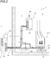
- This air conditioning system (1) comprises a heat pump (3) located outside the dwelling (2) to be equipped with it and a heating device (4) for fuel to be placed inside. of said dwelling (2).
- the fuel heater (4) is preferably a hearth chimney (5) or a solid fuel stove, for example a wood burning fireplace or a pellet stove.
- a hearth fireplace (5) the latter comprises a fireplace (6), for example closed by a glass door (7).
- This fireplace (6) is placed in a hearth (7) and has a duct (8) for combustion gases and fumes.
- the fuel heater (4) is equipped with an air circulation device (9) which draws air from the house (2) to pass through a first heat exchanger (10) and then to diffuse it in the dwelling (2).
- the air circulation device (9) comprises a ventilation network (11) for distributing temperature-conditioned air.
- This ventilation network (11) comprises at least one duct (12) or similar air passage connected to at least one air inlet (13) which opens into the dwelling (2), preferably in the lower part of the house. 'a living room.
- the at least one duct (12) or similar air passage is also connected to at least one air outlet (14) which opens into the dwelling (2), preferably in the upper part of a room residential.
- the air circulation device (9) also comprises a fan (15) or a turbine which draws air from the dwelling (2) at the level of the at least one air inlet (13) and blows in the dwelling (2) at the level of the at least one air outlet (14) after having made it pass through the at least one duct (12) of the ventilation network (11).
- This air flow is represented by white arrows bearing the reference 16 on the figure 1 .
- the first heat exchanger (10) is placed in the air network (11), preferably in the lower part thereof, between the at least one air inlet (13) and the at least one outlet of air (14) so that the air flowing in the aeraulic network (11) also passes through the first heat exchanger (10).
- the fuel heater (4) When the fuel heater (4) is in operation, it heats the air flowing in the air network (11) of the air circulation device (9).
- the aeraulic network (11) is preferably in the immediate vicinity of a hot part of the heating device (4).
- at least one duct (12) is in the immediate vicinity of the hearth (6) when the heating device (4) is a hearth chimney (5).
- the heat pump (3) is preferably reversible and operates by means of a first heat transfer fluid.
- the heat pump (3) has a device for exchanging calories or frigories (17) with the outside.
- its caloric or frigory exchange device (17) exchanges calories or frigories with the outside air to heat or cool a second heat exchanger (18). to which it is connected.
- the principle of the invention is based on the use of the second heat exchanger heat pump (18) for heating or cooling at least part of the dwelling according to whether the heat pump (3) is operating as a heating or cooling device.
- the first heat transfer fluid that it uses is preferably a type R410 refrigerant.
- the first heat transfer fluid is usually a toxic fluid and / or flammable or highly flammable or explosive and its use in a home is generally not tolerated by the regulations in force and its use incompatible with a fireplace or stove.
- the invention is characterized in that the first heat exchanger (10) exchanges its calories or its frigories with the second heat exchanger (18) via a circulation device (19) loop of a second coolant.
- This second heat transfer fluid is intended to be used in the house (2), it is a heat transfer fluid non-toxic and non-flammable.
- the second heat transfer fluid is preferably water, optionally supplemented with antifreeze.
- the circulation device (19) in loop of the second heat transfer fluid connects the first heat exchanger (10) to the second heat exchanger (18) and allows the exchange of calories or frigories between these two heat exchangers (10, 18). ).
- the circulation device (19) usually comprises a recirculation pump (20) circulating the second heat transfer fluid in a loop between the two heat exchangers (10, 18).
- the heat pump (3) takes heat from outside the house (2) via its heating device. exchange of calories or frigories (17), which cools the outside air and warms the second heat exchanger (18).
- the second heat exchanger (18) in turn heats the first heat exchanger (10) via the second heat transfer fluid.
- the air flowing through the first heat exchanger (10) through the air circulation device (9) is then heated by the first heat exchanger (10), and possibly by the heating device (4). it is functioning, in order to heat the dwelling (2).
- the heat pump (3) supplies frigories outside the house (2) via its cooling device. exchange of calories or frigories (17), which warms the outside air and cools the second heat exchanger (18).
- the second heat exchanger (18) in turn cools the first heat exchanger (10) through the second heat transfer fluid.
- the air flowing through the first heat exchanger (10) through the air circulation device (9) is then cooled by the first heat exchanger (10) to cool the house (2).
- the multi-energy reversible air conditioning system (1) of the invention also comprises a control device designed to control at least the operation of the heat pump (3) and the control device.
- This regulating device is intended to provide an additional comfort by a temperature of air as constant as possible corresponding to a temperature displayed, controlled or programmed for a living room.
- the multi-energy reversible air conditioning system (1) of the invention comprises at least a first temperature sensor (21) which measures the outside temperature, a second temperature sensor (22) which measures the temperature of the second heat transfer fluid and a third temperature sensor (23) which measures the temperature in the dwelling (2).
- the regulating device comprises a control box (25), for example in the form of a PLC, connected to said temperature sensors (21, 22, 23) and which is connected to the heat pump (3), to the fan (15) or the turbine of the air circulation device (9) and the recirculation pump (20) of the circulation device (19) to control its operation.
- a control box for example in the form of a PLC, connected to said temperature sensors (21, 22, 23) and which is connected to the heat pump (3), to the fan (15) or the turbine of the air circulation device (9) and the recirculation pump (20) of the circulation device (19) to control its operation.
- the multi-energy reversible air conditioning system (1) of the invention also comprises a fourth temperature sensor (24) which measures the temperature at the outlet of the at least one duct (12) of the invention. a somehowlic network (11).
- the control device is also connected to this fourth temperature sensor (21) and control the operation of the fan (15) or the turbine as a function of the temperature measured by said probe. So, for example, when the hearth fireplace is running and As wood is burned, the regulating device manages an appropriate speed of the fan (15) or the turbine.
- the multi-energy reversible air conditioning system (1) also comprises an air filter (36) which purifies the air entering the at least one duct (12) of the ventilation network. (11) at the air inlet (13). Between this air filter (36) and the fan (15) or the turbine, it can be provided a pressure sensor (37) which measures the pressure in the at least one duct (12) of the ventilation network (11) and which can for example be connected to the control box (25). Thus, in the event of even partial clogging of the air filter (36), the pressure sensor (37) can detect an unusual decrease in the pressure in the at least one duct (12) of the ventilation network (11) and transmit this information to the control box (25), which can for example signal to the user a need for maintenance for the air filter (36).
- an air filter (36) which purifies the air entering the at least one duct (12) of the ventilation network. (11) at the air inlet (13).
- a pressure sensor (37) which measures the pressure in the at least one duct (12) of the ventilation network (11) and which can for example be connected to
- the multi-energy reversible air conditioning system (1) may comprise an air filter (36) which purifies the air circulating at the outlet of the at least one duct (12) of the network. a crizlic (11), upstream of the air outlet (14).
- the pressure sensor (37) can detect an unusual overpressure in the at least one duct (12) of the ventilation network (11).
- the control box (25) is preferably located outside and integrated with the heat pump (3).
- the user may consult and modify the operating state of the multi-energy reversible air conditioning system (1) of the invention, it may comprise a control and display device (26), for example under the form of a display which reports to the user the operating parameters of the air conditioning system (1) and which also allows him to control the latter, namely to switch on, switch off and adjust the set temperature of the air conditioning system (1 ). These elements are then transmitted to the control box (25).
- a control and display device for example under the form of a display which reports to the user the operating parameters of the air conditioning system (1) and which also allows him to control the latter, namely to switch on, switch off and adjust the set temperature of the air conditioning system (1 ).
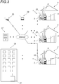
- the reversible multi-energy air conditioning system controller (1) of the invention is connected to a remote monitoring and control system.
- This monitoring and remote control system is provided to allow an operator and / or a user to remotely consult and control the control device.
- the remote monitoring and control system comprises a connection preferentially of the internet type, for example by wifi, or radio-frequency type, allowing the control device to transmit all the operating parameters of the reversible multi-energy air conditioning system (1). of the invention to a remote server (27), where this information is stored.
- This remote server (27) is preferably reserved for use by a manager (28) of the different air conditioning systems (1) connected to this remote server.
- This manager (28) can for example be the installer of air conditioning systems (1) or one of its partners.
- the operation of the multi-energy reversible air conditioning system (1) of the invention can be accessed, controlled and / or optimized remotely by the user and / or the manager ( 28) different air conditioning systems (1).
- control and / or remote optimization can be carried out for example by means of a computer (29), a tablet or a mobile phone (30) provided with a suitable application, or for example at the means of a remote installation (31) provided for this purpose and managed by the manufacturer and / or installer of the reversible multi-energy air conditioning system (1) of the invention, these different communication means being connected to the remote server (27), preferably via the Internet using secure communication protocols.
- the manager (28) can supervise the operation of all the different air conditioning systems (1) connected to the remote server (27). This allows him to remotely optimize the operation of the air conditioning systems (1), to program them for different temperatures depending on the day and time, but also to detect a possible failure in these air conditioning systems (1), turn them off when the user is away and turn them on in anticipation of the user's return.
- a consumer application uses a phone application portable device (30) which allows the user to connect to the remote server (27) and / or directly to the control and display device (26) of his multi-energy reversible air conditioning system (1) in order to manage his own installation.
- the reversible multi-energy air conditioning system (1) of the invention can also be associated with a hot water generation device (32), for example a water heater or a hot water tank.
- a hot water generation device for example a water heater or a hot water tank.
- a three-way valve (35) and provided on a pipe of the loop circulation device of a second heat transfer fluid (19), for example on its forward circuit.
- the second heat transfer fluid from the heat pump (3) is supplied either to the first heat exchanger (10) of the fuel heater (4) or at the third heat exchanger (33) of the hot water generating device (32).
- the temperature of the water in the hot water generating device (32) is measured by a fifth temperature sensor (34) and transmitted to the multi-energy reversible air conditioning system controller (1) of the invention, for example via the control box (25).
- a fifth temperature sensor (34) is measured by the multi-energy reversible air conditioning system controller (1) of the invention, for example via the control box (25).
- This controls the three-way valve (35) so the second heat transfer fluid from the heat pump (3) feeds either the first heat exchanger (10) or the third heat exchanger (33).
- the circulation device loop of a second coolant (19) can also bring calories or frigories to other heat exchange devices to cover all the needs of the home.
Landscapes
- Engineering & Computer Science (AREA)
- Chemical & Material Sciences (AREA)
- Combustion & Propulsion (AREA)
- Mechanical Engineering (AREA)
- General Engineering & Computer Science (AREA)
- Physics & Mathematics (AREA)
- Thermal Sciences (AREA)
- Life Sciences & Earth Sciences (AREA)
- Sustainable Development (AREA)
- Air Conditioning Control Device (AREA)
- Other Air-Conditioning Systems (AREA)
- Steam Or Hot-Water Central Heating Systems (AREA)
Applications Claiming Priority (1)
| Application Number | Priority Date | Filing Date | Title |
|---|---|---|---|
| FR1751429A FR3063130B1 (fr) | 2017-02-23 | 2017-02-23 | Systeme de climatisation multi-energie |
Publications (1)
| Publication Number | Publication Date |
|---|---|
| EP3367006A1 true EP3367006A1 (de) | 2018-08-29 |
Family
ID=58707775
Family Applications (1)
| Application Number | Title | Priority Date | Filing Date |
|---|---|---|---|
| EP18156343.8A Withdrawn EP3367006A1 (de) | 2017-02-23 | 2018-02-12 | Multienergie-klimatisierungssystem |
Country Status (2)
| Country | Link |
|---|---|
| EP (1) | EP3367006A1 (de) |
| FR (1) | FR3063130B1 (de) |
Cited By (1)
| Publication number | Priority date | Publication date | Assignee | Title |
|---|---|---|---|---|
| EP4621298A1 (de) | 2024-03-19 | 2025-09-24 | MCZ Group S.p.A. | Klimaanlage für innenräume |
Families Citing this family (1)
| Publication number | Priority date | Publication date | Assignee | Title |
|---|---|---|---|---|
| CN114383301B (zh) * | 2021-12-24 | 2024-03-19 | 青岛海尔空调器有限总公司 | 协同空调控制方法、装置、空调系统及电子设备 |
Citations (2)
| Publication number | Priority date | Publication date | Assignee | Title |
|---|---|---|---|---|
| US20010042610A1 (en) * | 2000-04-10 | 2001-11-22 | Lyons David Charles | Heat exchange system |
| FR2860061A1 (fr) * | 2003-09-24 | 2005-03-25 | Bernard Schreiber | Installation de chauffage et de climatisation |
-
2017
- 2017-02-23 FR FR1751429A patent/FR3063130B1/fr active Active
-
2018
- 2018-02-12 EP EP18156343.8A patent/EP3367006A1/de not_active Withdrawn
Patent Citations (2)
| Publication number | Priority date | Publication date | Assignee | Title |
|---|---|---|---|---|
| US20010042610A1 (en) * | 2000-04-10 | 2001-11-22 | Lyons David Charles | Heat exchange system |
| FR2860061A1 (fr) * | 2003-09-24 | 2005-03-25 | Bernard Schreiber | Installation de chauffage et de climatisation |
Cited By (1)
| Publication number | Priority date | Publication date | Assignee | Title |
|---|---|---|---|---|
| EP4621298A1 (de) | 2024-03-19 | 2025-09-24 | MCZ Group S.p.A. | Klimaanlage für innenräume |
Also Published As
| Publication number | Publication date |
|---|---|
| FR3063130A1 (fr) | 2018-08-24 |
| FR3063130B1 (fr) | 2021-04-30 |
Similar Documents
| Publication | Publication Date | Title |
|---|---|---|
| WO2014044864A1 (fr) | Installation de chauffe-eau sanitaire à fonction de chauffage | |
| EP3367006A1 (de) | Multienergie-klimatisierungssystem | |
| EP2603742B1 (de) | Verfahren und vorrichtung zur temperaturregulierung in einem gebäude | |
| EP1695010B1 (de) | Heiz- und luftklimatisierungsvorrichtung | |
| WO2008034828A1 (fr) | Systeme de gestion thermique de la climatisation et du refroidissement moteur d'un vehicule automobile, comprenant notamment un refroidisseur de gaz | |
| US20070284454A1 (en) | Secondary heating system | |
| FR2953889A1 (fr) | Circuit d'echange de calories et procede de regulation thermique d'un fluide caloporteur circulant dans un moteur thermique d'un vehicule automobile | |
| FR2920222A1 (fr) | Dispositif de chauffage | |
| EP2527750B1 (de) | thermodynamischer wassererhitzer | |
| EP3910249B1 (de) | System zur erzeugung und verteilung von wärme und kälte und sein steuerungsverfahren | |
| EP3367016B1 (de) | System zur thermischen steuerung von luft und der sanitären heisswasserproduktion in einem raum | |
| EP3581853B1 (de) | Wärmeübertragungsmodul für die erzeugung von warmwasser | |
| EP0117796B1 (de) | Klimaanlage für ein Gebäude | |
| EP3412976B1 (de) | Heizsystem zum beheizen der räume einer wohnung, das ein hauptheizgerät und eine luftverteilungsanlage umfasst | |
| EP1980794B1 (de) | Gas-Luftheizgerät mit umkehrbarer Klimaanlage | |
| FR2766909A1 (fr) | Procede et dispositif pour detecter une pression excessive d'un fluide refrigerant dans un condenseur d'une boucle de climatisation | |
| FR2776757A1 (fr) | Climatiseur assurant le chauffage et le refroidissement | |
| FR3088990A1 (fr) | Installation de chauffage | |
| FR2913755A1 (fr) | Dispositif de ventilation pour echangeur thermique | |
| EP2461108B1 (de) | Wandheizvorrichtung, Ausstattung zum Aufheizen einer Flüssigkeit, Heizanlage eines Lokals und Anpassungsverfahren einer Wandheizvorrichtung | |
| FR2913757A1 (fr) | Dispositif de couplage d'un systeme de chauffage a liquide caloporteur a un dispositif de refroidissement | |
| FR3095262A1 (fr) | Système de chauffage ou rafraîchissement d’air et de production d’eau chaude sanitaire | |
| LU84915A1 (fr) | Dispositif et moyens de controle d'installations de conditionnement de locaux | |
| FR3023359A1 (fr) | Batiment equipe d'un chauffe-eau thermodynamique, d'un systeme de ventilation mecanique controlee et d'une ou plusieurs sources auxiliaires, et procede de regulation du chauffe-eau thermodynamique | |
| EP3742062A1 (de) | Wärmetauscher mit doppelkreislauf |
Legal Events
| Date | Code | Title | Description |
|---|---|---|---|
| PUAI | Public reference made under article 153(3) epc to a published international application that has entered the european phase |
Free format text: ORIGINAL CODE: 0009012 |
|
| AK | Designated contracting states |
Kind code of ref document: A1 Designated state(s): AL AT BE BG CH CY CZ DE DK EE ES FI FR GB GR HR HU IE IS IT LI LT LU LV MC MK MT NL NO PL PT RO RS SE SI SK SM TR |
|
| AX | Request for extension of the european patent |
Extension state: BA ME |
|
| STAA | Information on the status of an ep patent application or granted ep patent |
Free format text: STATUS: THE APPLICATION IS DEEMED TO BE WITHDRAWN |
|
| 18D | Application deemed to be withdrawn |
Effective date: 20190301 |