EP3366585A1 - Vertical take-off and landing aircraft - Google Patents
Vertical take-off and landing aircraft Download PDFInfo
- Publication number
- EP3366585A1 EP3366585A1 EP17756064.6A EP17756064A EP3366585A1 EP 3366585 A1 EP3366585 A1 EP 3366585A1 EP 17756064 A EP17756064 A EP 17756064A EP 3366585 A1 EP3366585 A1 EP 3366585A1
- Authority
- EP
- European Patent Office
- Prior art keywords
- landing aircraft
- vertical takeoff
- ducted
- airframe
- ducted fans
- Prior art date
- Legal status (The legal status is an assumption and is not a legal conclusion. Google has not performed a legal analysis and makes no representation as to the accuracy of the status listed.)
- Withdrawn
Links
Images


Classifications
-
- B—PERFORMING OPERATIONS; TRANSPORTING
- B64—AIRCRAFT; AVIATION; COSMONAUTICS
- B64C—AEROPLANES; HELICOPTERS
- B64C29/00—Aircraft capable of landing or taking-off vertically, e.g. vertical take-off and landing [VTOL] aircraft
- B64C29/0008—Aircraft capable of landing or taking-off vertically, e.g. vertical take-off and landing [VTOL] aircraft having its flight directional axis horizontal when grounded
- B64C29/0016—Aircraft capable of landing or taking-off vertically, e.g. vertical take-off and landing [VTOL] aircraft having its flight directional axis horizontal when grounded the lift during taking-off being created by free or ducted propellers or by blowers
- B64C29/0025—Aircraft capable of landing or taking-off vertically, e.g. vertical take-off and landing [VTOL] aircraft having its flight directional axis horizontal when grounded the lift during taking-off being created by free or ducted propellers or by blowers the propellers being fixed relative to the fuselage
-
- B—PERFORMING OPERATIONS; TRANSPORTING
- B64—AIRCRAFT; AVIATION; COSMONAUTICS
- B64C—AEROPLANES; HELICOPTERS
- B64C27/00—Rotorcraft; Rotors peculiar thereto
- B64C27/04—Helicopters
- B64C27/08—Helicopters with two or more rotors
-
- B—PERFORMING OPERATIONS; TRANSPORTING
- B64—AIRCRAFT; AVIATION; COSMONAUTICS
- B64C—AEROPLANES; HELICOPTERS
- B64C27/00—Rotorcraft; Rotors peculiar thereto
- B64C27/20—Rotorcraft characterised by having shrouded rotors, e.g. flying platforms
-
- B—PERFORMING OPERATIONS; TRANSPORTING
- B64—AIRCRAFT; AVIATION; COSMONAUTICS
- B64C—AEROPLANES; HELICOPTERS
- B64C27/00—Rotorcraft; Rotors peculiar thereto
- B64C27/52—Tilting of rotor bodily relative to fuselage
-
- B—PERFORMING OPERATIONS; TRANSPORTING
- B64—AIRCRAFT; AVIATION; COSMONAUTICS
- B64C—AEROPLANES; HELICOPTERS
- B64C29/00—Aircraft capable of landing or taking-off vertically, e.g. vertical take-off and landing [VTOL] aircraft
-
- B—PERFORMING OPERATIONS; TRANSPORTING
- B64—AIRCRAFT; AVIATION; COSMONAUTICS
- B64C—AEROPLANES; HELICOPTERS
- B64C39/00—Aircraft not otherwise provided for
- B64C39/02—Aircraft not otherwise provided for characterised by special use
-
- B—PERFORMING OPERATIONS; TRANSPORTING
- B64—AIRCRAFT; AVIATION; COSMONAUTICS
- B64U—UNMANNED AERIAL VEHICLES [UAV]; EQUIPMENT THEREFOR
- B64U10/00—Type of UAV
- B64U10/10—Rotorcrafts
- B64U10/13—Flying platforms
-
- B—PERFORMING OPERATIONS; TRANSPORTING
- B64—AIRCRAFT; AVIATION; COSMONAUTICS
- B64U—UNMANNED AERIAL VEHICLES [UAV]; EQUIPMENT THEREFOR
- B64U30/00—Means for producing lift; Empennages; Arrangements thereof
- B64U30/20—Rotors; Rotor supports
- B64U30/26—Ducted or shrouded rotors
-
- B—PERFORMING OPERATIONS; TRANSPORTING
- B64—AIRCRAFT; AVIATION; COSMONAUTICS
- B64U—UNMANNED AERIAL VEHICLES [UAV]; EQUIPMENT THEREFOR
- B64U50/00—Propulsion; Power supply
- B64U50/10—Propulsion
- B64U50/13—Propulsion using external fans or propellers
- B64U50/14—Propulsion using external fans or propellers ducted or shrouded
-
- B—PERFORMING OPERATIONS; TRANSPORTING
- B64—AIRCRAFT; AVIATION; COSMONAUTICS
- B64U—UNMANNED AERIAL VEHICLES [UAV]; EQUIPMENT THEREFOR
- B64U50/00—Propulsion; Power supply
- B64U50/10—Propulsion
- B64U50/11—Propulsion using internal combustion piston engines
-
- B—PERFORMING OPERATIONS; TRANSPORTING
- B64—AIRCRAFT; AVIATION; COSMONAUTICS
- B64U—UNMANNED AERIAL VEHICLES [UAV]; EQUIPMENT THEREFOR
- B64U50/00—Propulsion; Power supply
- B64U50/30—Supply or distribution of electrical power
Landscapes
- Engineering & Computer Science (AREA)
- Aviation & Aerospace Engineering (AREA)
- Mechanical Engineering (AREA)
- Chemical & Material Sciences (AREA)
- Combustion & Propulsion (AREA)
- Remote Sensing (AREA)
- Structures Of Non-Positive Displacement Pumps (AREA)
- Toys (AREA)
Abstract
Description
- Embodiments disclosed herein relate to a vertical takeoff and landing aircraft, and more particularly, to a vertical takeoff and landing aircraft having a plurality of ducted fans.
- Currently, a representative example of the vertical takeoff and landing aircraft which can generate lift without running on the ground is a helicopter. The helicopter has a large main rotor as compared to an airframe and obtains lift and thrust by rotating the main rotor. Also, anti-torque acting on the airframe by rotation of the main rotor is generally cancelled out using a tail rotor and the like (see, for example, Patent Document 1).
- Also, in recent years, an unmanned vertical takeoff and landing aircraft called a drone has been being developed. Such a vertical takeoff and landing aircraft generally obtains lift and thrust by rotating a plurality of rotors. Also, the anti-torque acting on the airframe by rotation of these rotors is cancelled out, for example, by rotating half the rotors in a direction opposite to the other half (see, for example, Patent Document 2).
-
- Patent Document 1: Japanese Patent Laid-Open No.
6-286696 - Patent Document 2: Japanese Patent Laid-Open No.
2014-240242 - However, with a helicopter-type vertical takeoff and landing aircraft such as described in
Patent Document 1, the main rotor is large, and the airframe tends to increase in size to mount the tail rotor and the like. Therefore, if this type of vertical takeoff and landing aircraft performs a takeoff, a landing, or attitude control in a small space in which obstacles such as buildings, trees, and/or the like exist, the main rotor, tail rotor, or the like will touch any of the obstacles. Thus, the vertical takeoff and landing aircraft requires a large space for takeoffs and landings. - Also, with the drone-type vertical takeoff and landing aircraft described in
Patent Document 2, a rotational direction of the plurality of rotors has to be controlled in a complicated manner. Also, if power transmitted to the rotors is reversed using a mechanism such as a reversing gear, there are problems in that a structure becomes complicated, that weight of the airframe becomes increased, and so on. - The present disclosure has been made in view of the problems described above and has an object to provide a vertical takeoff and landing aircraft which can reduce an impact of anti-torque acting on an airframe, using a simple structure.
- The present disclosure provides a vertical takeoff and landing aircraft which includes a plurality of ducted fans in an airframe, in which each of the ducted fans is inclined tangentially to a rotational direction on a side farther from other ducted fans.
- Inclination directions of the ducted fans may be perpendicular to a line segment connecting an airframe center located at an equal distance and a shortest distance from rotation centers of the plurality of ducted fans and the rotation center on a plan view of the vertical takeoff and landing aircraft. Also, the airframe may include a power source which supplies power to the ducted fan and an output shaft of the power source may be placed on the airframe center on the plan view of the vertical takeoff and landing aircraft. Furthermore, the plurality of ducted fans may be rotated in a same direction by the power source.
- Also, each of the ducted fans may include a control vane with an adjustable angle of attack, the control vane being installed in an outlet portion of the ducted fan. Also, the airframe may include a propulsion device for attitude control.
- With the vertical takeoff and landing aircraft according to the present disclosure described above, since each of the ducted fans is inclined tangentially to the rotational direction of a rotating shaft, a component force of thrust is generated in an inclination direction and the component forces generated on each of the ducted fans can generate offset torque which cancels out anti-torque. This eliminates the need to install a tail rotor and the like as with helicopter-type vertical takeoff and landing aircraft and the need to control the rotational directions of the plurality of ducted fans as with drone-type vertical takeoff and landing aircraft, and thus an impact of anti-torque can be reduced using a simple structure.
-
-
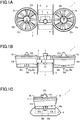
FIG. 1A is a plan view of a vertical takeoff and landing aircraft according to a first embodiment of the present disclosure. -
FIG. 1B is a front view of the vertical takeoff and landing aircraft according to the first embodiment of the present disclosure. -
FIG. 1C is a side view of the vertical takeoff and landing aircraft according to the first embodiment of the present disclosure. -
FIG. 2A is a conceptual diagram showing generation of anti-torque in the vertical takeoff and landing aircraft according to the first embodiment of the present disclosure. -
FIG. 2B is a conceptual diagram showing generation of component forces of thrust in the vertical takeoff and landing aircraft according to the first embodiment of the present disclosure. -
FIG. 2C is a conceptual diagram showing generation of offset torque in the vertical takeoff and landing aircraft according to the first embodiment of the present disclosure. -
FIG. 3A is a conceptual plan view showing a first variation of the vertical takeoff and landing aircraft according to the first embodiment of the present disclosure. -
FIG. 3B is a conceptual plan view showing a second variation of the vertical takeoff and landing aircraft according to the first embodiment of the present disclosure. -
FIG. 4A is a plan view of a vertical takeoff and landing aircraft according to a second embodiment of the present disclosure. -
FIG. 4B is a front view of the vertical takeoff and landing aircraft according to the second embodiment of the present disclosure. -
FIG. 4C is a side view of the vertical takeoff and landing aircraft according to the second embodiment of the present disclosure. -
FIG. 5A is a plan view of a vertical takeoff and landing aircraft according to a third embodiment of the present disclosure. -
FIG. 5B is a front view of the vertical takeoff and landing aircraft according to the third embodiment of the present disclosure. -
FIG. 5C is a side view of the vertical takeoff and landing aircraft according to the third embodiment of the present disclosure. - Embodiments of the present disclosure will be described below with reference to
FIGS. 1A to 5C .FIGS. 1A to 1C are diagrams showing a vertical takeoff and landing aircraft according to a first embodiment of the present disclosure, whereFIG. 1A is a plan view,FIG. 1B is a front view, andFIG. 1C is a side view.FIGS. 2A to 2C are explanatory diagrams showing operation of the vertical takeoff and landing aircraft according to the first embodiment of the present disclosure, whereFIG. 2A is a conceptual diagram showing generation of anti-torque,FIG. 2B is a conceptual diagram showing generation of component forces of thrust, andFIG. 2C is a conceptual diagram showing generation of offset torque. - As shown in
FIGS. 1A to 2C , the vertical takeoff andlanding aircraft 1 according to the first embodiment of the present disclosure is made up of a pair ofducted fans frame 4 adapted to couple together theducted fans power source 5 adapted to supply power to theducted fans legs 6 adapted to support anairframe 2 at the time of landing. Note that theairframe 2 is made up of theducted fans frame 4, and accessories (power source 5,legs 6, and the like) thereof. - The
ducted fan 3a is placed on the right side of theframe 4 in front view, for example, as shown inFIG. 1B . Also, theducted fan 3b is placed on the left side of theframe 4 in front view, for example, as shown inFIG. 1B . Theducted fan 3a andducted fan 3b are coupled integrally by theframe 4 connected therebetween. Then, one 3a (3b) of the ducted fans is inclined tangentially to a rotational direction on the side farther from the otherducted fan 3b (3a) . - The
ducted fans cylindrical ducts fans ducts nose cones fans tail cones fans stators ducts tail cones ducted fans - The
nose cones fans ducts stators ducts fans power source 5 may be placed in some of thestators tail cones ducts - Also, the
ducted fans control vanes control vanes ducts tail cones fans ducted fans control vanes tail cones ducts control vanes control vanes airframe 2 and a pair ofcontrol vanes 37a and 37b pivoted in a left-right direction of theairframe 2. - By pivoting the
control vanes ducted fans airframe 2. Also, thecontrol vanes airframe 2, but also to control an attitude of theairframe 2. - The
frame 4 is a member adapted to couple together the pair ofducted fans ducts frame 4 may be made of either metal or resin. Thepower source 5 may be placed on a top face of theframe 4. Thepower source 5 is, for example, an engine driven by fuel. By adopting an engine as apower source 5, it is possible to drive largeducted fans - Note that the
power source 5 may be placed on an underside of theframe 4 or in rear part of theframe 4. Also, thepower source 5 is not limited to an engine, and when thefans power source 5 may be a battery (e.g., a storage battery, fuel cell, solar cell, or the like) capable of supplying electric power to the electric motors. - Also, a power transmission mechanism adapted to transmit power generated by the
power source 5 to thefans frame 4. As shown inFIG. 2C , the power transmission mechanism includes, for example, anoutput shaft 51 rotated by thepower source 5, rotatingshafts fans belts output shaft 51 androtating shafts belts ducts stators output shaft 51 androtating shafts - Note that the power transmission mechanism is not limited to the illustrated belt transmission mechanism, and may be a gear transmission mechanism using a shaft and bevel gears or a chain transmission mechanism using a chain and sprocket. Also, the power transmission mechanism may include a speed reducer mechanism or speed-up mechanism. Furthermore, when the
fans power source 5. - Also, a pair of
legs 6 adapted to touch the ground at the time of landing is installed on the underside of theframe 4. Each of thelegs 6 is constructed from a plate formed, for example, into a C shape and opposite ends of the leg are connected to theframe 4. Theleg 6 forms a ring shape in conjunction with theframe 4, thereby acquiring elasticity and thus a capability to cushion the shock of landing. Note that thelegs 6 are not limited to the illustrated configuration, and may be constructed from three or more rod-shaped members or made up of long plates adapted to touch the ground at the time of landing and support members connected to theframe 4. - Also, a
connector 41 adapted to support a payload C may be installed on the underside of theframe 4. InFIGS. 1A to 1C , the payload C is illustrated by alternate long and short dash lines for convenience of explanation. The payload C is, for example, photographic equipment such as a camera, surveying equipment, relief supplies, or the like. - Also, a control device (not shown) adapted to control output of the
power source 5, rotation speed of theducted fans control vanes frame 4. The control device may be configured to automatically pilot the vertical takeoff andlanding aircraft 1 based on a program inputted in advance or configured to allow the vertical takeoff andlanding aircraft 1 to be piloted remotely with a remote control or the like. - Here, a vertical takeoff and landing aircraft 1' shown in
FIG. 2A includesducted fans 3a' and 3b' in which rotatingshafts 52a' and 52b' are oriented in a vertical direction. Power is transmitted to therotating shafts 52a' and 52b' via an output shaft 51' andbelts 53a' and 53b'. Now, if both theducted fans 3a' and 3b' (not shown) are rotated in a same direction (e.g., a clockwise direction inFIG. 2A ), anti-torque Tr acts on an airframe 2' in a counterclockwise direction inFIG. 2A as a reaction to the rotation of theducted fans 3a' and 3b'. Therefore, if no measure is taken, the airframe 2' rotates in the counterclockwise direction inFIG. 2A , making stable flight difficult. - Thus, according to the present embodiment, the
ducted fans frame 4 by being inclined in a predetermined direction. For example, as shown inFIG. 2B , a center line La of therotating shaft 52a of theducted fan 3a is inclined forward at an angle of θ to a vertical line Lv. Also, a center line Lb of therotating shaft 52b of theducted fan 3b is inclined rearward at an angle of θ to the vertical line Lv. The angle of θ is set to a range in which theairframe 2 will not rotate when the vertical takeoff andlanding aircraft 1 is hovering. Specifically, the angle θ is set, for example, within a range of 1 to 10 degrees, and preferably to around 4 to 6 degrees. Note that the inclination angle θ of therotating shaft 52a of theducted fan 3a and the inclination angle θ of therotating shaft 52b of theducted fan 3b are set to a same value. - Also, in line with the inclination of the
rotating shafts ducts fans nose cones tail cones stators ducted fans ducted fan 3a is inclined forward at an angle of θ to the vertical line Lv and theducted fan 3b is inclined rearward at an angle of θ to the vertical line Lv. Note thatFIG. 2B shows a side view of theducted fans - In the
ducted fan 3a in which therotating shaft 52a is inclined forward, thrust Fa directed toward upper left inFIG. 2B is generated, generating a component force Fha directed forward. Also, in theducted fan 3b in which therotating shaft 52b is inclined rearward, thrust Fb directed toward upper right inFIG. 2B is generated, generating a component force Fhb directed rearward. - If the component forces Fha and Fhb are illustrated on the plan view shown in
FIG. 2C , in theducted fan 3a, the component force Fha is generated in a downward direction inFIG. 2C and in theducted fan 3b, the component force Fhb is generated in an upward direction inFIG. 2C . The component forces Fha and Fhb generate offset torque Tc which rotates theairframe 2 clockwise inFIG. 2C . Therefore, the offset torque Tc can cancel out anti-torque Tr. - Note that in
FIG. 2C , for convenience of explanation, parts showing an inner side of theducted fans rotating shafts output shaft 51, the adoption of thebelts rotating shafts output shaft 51. - As shown in
FIG. 2C , it can be said that theducted fan 3a described above has itsrotating shaft 52a inclined tangentially to the rotational direction on the side farther from the otherducted fan 3b (i.e., in the downward direction inFIG. 2C ). Also, it can be said that theducted fan 3b has itsrotating shaft 52b inclined tangentially to the rotational direction on the side farther from the otherducted fan 3a (i.e., in the upward direction inFIG. 2C ). - Also, on a plan view of the vertical takeoff and
landing aircraft 1, if a point located at an equal distance and the shortest distance from rotation centers Of (i.e., centers of therotating shafts ducted fans ducted fans ducted fans output shaft 51 is placed, for example, on the airframe center Op. - By defining the rotation centers Of and airframe center Op in this way on a plan view of the vertical takeoff and
landing aircraft 1, the inclination directions of theducted fans airframe 2. Also, by bringing theoutput shaft 51 into coincidence with the airframe center Op, a power transmission mechanism of a substantially identical configuration can be adopted for the pair ofducted fans - Now,
FIGS. 3A and 3B are conceptual plan views showing variations of the vertical takeoff and landing aircraft according to the first embodiment of the present disclosure, whereFIG. 3A shows a first variation andFIG. 3B shows a second variation. The first variation shown inFIG. 3A is a vertical takeoff andlanding aircraft 1 equipped with threeducted fans FIG. 3B is a vertical takeoff andlanding aircraft 1 equipped with fourducted fans FIGS. 3A and 3B illustrate conceptualized configurations of theairframe 2. - In the vertical takeoff and
landing aircraft 1 according to the first variation shown inFIG. 3A , theducted fan 3a is inclined tangentially to the rotational direction on the side farther from the otherducted fans ducted fan 3b is inclined tangentially to the rotational direction on the side farther from the otherducted fans ducted fan 3c is inclined tangentially to the rotational direction on the side farther from the otherducted fans - By inclining the
ducted fans ducted fans FIG. 3A . Note that concrete configurations of theducted fans ducted fans - In the vertical takeoff and
landing aircraft 1 according to the second variation shown inFIG. 3B , theducted fan 3a is inclined tangentially to the rotational direction on the side farther from the otherducted fans ducted fan 3b is inclined tangentially to the rotational direction on the side farther from the otherducted fans ducted fan 3c is inclined tangentially to the rotational direction on the side farther from the otherducted fans ducted fan 3d is inclined tangentially to the rotational direction on the side farther from the otherducted fans - By inclining the
ducted fans ducted fans FIG. 3B . Note that concrete configurations of theducted fans ducted fans - Next, vertical takeoff and
landing aircraft 1 according to other embodiments of the present disclosure will be described with reference toFIGS 4A to 5C .FIGS 4A to 4C are diagrams showing a vertical takeoff and landing aircraft according to a second embodiment of the present disclosure, whereFIG. 4A is a plan view,FIG. 4B is a front view, andFIG. 4C is a side view.FIGS 5A to 5C are diagrams showing a vertical takeoff and landing aircraft according to a third embodiment of the present disclosure, whereFIG. 5A is a plan view,FIG. 5B is a front view, andFIG. 5C is a side view. Note that components in common with the vertical takeoff andlanding aircraft 1 according to the first embodiment described above are denoted by the same reference numerals as the corresponding components of the first embodiment, and redundant description thereof will be omitted. - The vertical takeoff and
landing aircraft 1 according to the second embodiment shown inFIGS 4A to 4C includesfirst propulsion devices 7 adapted to control rotational motion (rolling) around an X axis (front-rear axis) of theairframe 2 and rotational motion (pitching) around a Y axis (left-right axis) of theairframe 2, andsecond propulsion devices 8 adapted to control rotational motion (yawing) around a Z axis (up-down axis) of theairframe 2. Thefirst propulsion devices 7 andsecond propulsion devices 8 are intended for attitude control of theairframe 2 and are made up, for example, of electric fans. Note that thefirst propulsion devices 7 andsecond propulsion devices 8 may be propulsion devices other than electric fans. - The
first propulsion devices 7 are placed, for example, in locations corresponding to four corners of theairframe 2. Also, thefirst propulsion devices 7 are placed in such a way as to be able to generate thrust directed downward in the vertical direction with theairframe 2 held horizontally. By adjusting the thrust of fourfirst propulsion devices 7 appropriately, it is possible to control rolling and pitching as desired. - The
second propulsion devices 8 are placed, for example, in front of and behind a central portion of theframe 4. Also, thesecond propulsion devices 8 are placed in such a way as to be able to generate thrust in a Y direction (left-right direction) with theairframe 2 held horizontally. By adjusting the thrust of the twosecond propulsion devices 8 appropriately, it is possible to control yawing as desired. - The vertical takeoff and
landing aircraft 1 according to the third embodiment shown inFIGS 5A to 5C includesthird propulsion devices 9 adapted to control rotational motion (rolling) around the X axis (front-rear axis) of theairframe 2, rotational motion (pitching) around the Y axis (left-right axis), and rotational motion (yawing) around the Z axis (up-down axis). Thethird propulsion devices 9 are intended for attitude control of theairframe 2 and are made up, for example, of electric fans. Note that thethird propulsion devices 9 may be propulsion devices other than electric fans. - The
third propulsion devices 9 are placed, for example, in locations corresponding to four corners of theairframe 2. Also, thethird propulsion devices 9 are placed in such a way as to be able to generate thrust directed obliquely downward in a direction away from theairframe 2 with theairframe 2 held horizontally. Specifically, thethird propulsion device 9 installed in theducted fan 3a is placed with upper part of the rotating shaft inclined toward the rotation center of theducted fan 3a and thethird propulsion device 9 installed in theducted fan 3b is placed with upper part of the rotating shaft inclined toward the rotation center of theducted fan 3b. - By adjusting the thrust of the four
third propulsion devices 9 appropriately, it is possible to control rolling, pitching, and yawing as desired. Also, the third embodiment can reduce the number of electric fans for attitude control compared to the second embodiment described above and thereby reduce the weight of theairframe 2. - The vertical takeoff and
landing aircraft 1 according to the second embodiment and third embodiment described above do not have control vanes in the outlet portions of theducted fans landing aircraft 1 according to the second embodiment may be designed to control the traveling direction of theairframe 2 by adjusting the directions of the thrust generated by theducted fans first propulsion devices 7 andsecond propulsion devices 8. Also, the vertical takeoff andlanding aircraft 1 according to the third embodiment may be designed to control the traveling direction of theairframe 2 by adjusting the directions of the thrust generated by theducted fans third propulsion device 9. Of course, the vertical takeoff andlanding aircraft 1 according to the second embodiment and third embodiment may also have control vanes installed in the outlet portions of theducted fans - The vertical takeoff and
landing aircraft 1 according to the first embodiment to third embodiment have been described above as being unmanned aircraft, but may be manned aircraft with seats installed on theframe 4. - The present disclosure is not limited to the embodiments described above, and needless to say, various changes can be made without departing from the spirit and scope of the present disclosure.
-
- 1 Vertical takeoff and landing aircraft
- 2 Airframe
- 3a, 3b, 3c, 3d Ducted fan
- 4 Frame
- 5 Power source
- 6 Leg
- 7 First propulsion device
- 8 Second propulsion device
- 9 Third propulsion device
- 31a, 31b Duct
- 32a, 32b Fan
- 33a, 33b Nose cone
- 34a, 34b Tail cone
- 35a, 35b Stator
- 36a, 36b, 37a, 37b Control vane
- 41 Connectors
- 51 Output shaft
- 52a, 52b Rotating shaft
- 53a, 53b Belt
Claims (6)
- A vertical takeoff and landing aircraft which includes a plurality of ducted fans in an airframe, wherein
each of the ducted fans is inclined tangentially to a rotational direction on a side farther from other ducted fans. - The vertical takeoff and landing aircraft according to claim 1, wherein inclination directions of the ducted fans are perpendicular to a line segment connecting an airframe center located at an equal distance and a shortest distance from rotation centers of the plurality of ducted fans and the rotation center on a plan view of the vertical takeoff and landing aircraft.
- The vertical takeoff and landing aircraft according to claim 2, wherein the airframe includes a power source which supplies power to the ducted fan and an output shaft of the power source is placed on the airframe center on the plan view of the vertical takeoff and landing aircraft.
- The vertical takeoff and landing aircraft according to claim 3, wherein the plurality of ducted fans is rotated in a same direction by the power source.
- The vertical takeoff and landing aircraft according to claim 1, wherein each of the ducted fans includes a control vane with an adjustable angle of attack, the control vane being installed in an outlet portion of the ducted fan.
- The vertical takeoff and landing aircraft according to claim 1, wherein the airframe includes a propulsion device for attitude control.
Applications Claiming Priority (2)
| Application Number | Priority Date | Filing Date | Title |
|---|---|---|---|
| JP2016035226 | 2016-02-26 | ||
| PCT/JP2017/002502 WO2017145622A1 (en) | 2016-02-26 | 2017-01-25 | Vertical take-off and landing aircraft |
Publications (2)
| Publication Number | Publication Date |
|---|---|
| EP3366585A1 true EP3366585A1 (en) | 2018-08-29 |
| EP3366585A4 EP3366585A4 (en) | 2019-07-31 |
Family
ID=59685458
Family Applications (1)
| Application Number | Title | Priority Date | Filing Date |
|---|---|---|---|
| EP17756064.6A Withdrawn EP3366585A4 (en) | 2016-02-26 | 2017-01-25 | Vertical take-off and landing aircraft |
Country Status (6)
| Country | Link |
|---|---|
| US (1) | US20180297697A1 (en) |
| EP (1) | EP3366585A4 (en) |
| JP (1) | JP6478080B2 (en) |
| AU (1) | AU2017224522B2 (en) |
| NZ (1) | NZ742223A (en) |
| WO (1) | WO2017145622A1 (en) |
Families Citing this family (19)
| Publication number | Priority date | Publication date | Assignee | Title |
|---|---|---|---|---|
| CN106043679B (en) * | 2016-07-28 | 2018-09-07 | 易瓦特科技股份公司 | Multiaxis power source unmanned flight's equipment |
| US20180022453A1 (en) * | 2016-12-31 | 2018-01-25 | Haoxiang Electric Energy (Kunshan) Co., Ltd. | Flying machine and flying unit |
| US10974825B2 (en) * | 2017-10-11 | 2021-04-13 | Hangzhou Zero Zero Technology Co., Ltd . | Aerial system including foldable frame architecture |
| CN108298074A (en) * | 2018-03-14 | 2018-07-20 | 长沙市云智航科技有限公司 | The component that verts for the more rotor flying vehicles of manned duct |
| CN109466742B (en) * | 2018-12-03 | 2023-09-12 | 北京电子工程总体研究所 | Aircraft frame and aircraft thereof |
| US11591087B2 (en) * | 2019-04-07 | 2023-02-28 | Donald Lee Chalker | Unmanned aerial vehicle with ducted rotors |
| WO2021070262A1 (en) * | 2019-10-08 | 2021-04-15 | 株式会社A.L.I. Technologies | Aircraft |
| JP7374828B2 (en) * | 2020-03-23 | 2023-11-07 | 三菱重工業株式会社 | Ducted fan equipment and aircraft |
| JP6902307B1 (en) * | 2021-02-26 | 2021-07-14 | 株式会社エアロネクスト | An air vehicle and a mounting unit having a mounting unit having a means of transportation. |
| CN115230951A (en) * | 2021-04-24 | 2022-10-25 | 范长亮 | An aircraft and its control device |
| CN113978714B (en) * | 2021-07-12 | 2023-04-07 | 南京航空航天大学 | Tilting runner edge duct propulsion device for vertical take-off and landing high-speed aircraft |
| CN113415411B (en) * | 2021-07-28 | 2022-03-11 | 涵涡智航科技(玉溪)有限公司 | A double-ducted unmanned aerial vehicle |
| TWM621488U (en) * | 2021-08-19 | 2021-12-21 | 林瑤章 | Unmanned aerial device having cleaning function |
| US12065237B2 (en) * | 2021-10-15 | 2024-08-20 | Arizona Board Of Regents On Behalf Of The University Of Arizona | Flight duration enhancement for single rotorcraft and multicopters |
| CN114275156B (en) * | 2021-12-31 | 2022-10-28 | 哈尔滨工业大学 | Thrust vector unmanned vehicles based on duct fan |
| CN114802724B (en) * | 2022-03-23 | 2025-03-28 | 北京航空航天大学 | Aircraft and control method thereof |
| JP7249074B1 (en) * | 2022-08-24 | 2023-03-30 | 株式会社Flight PILOT | flying mobile |
| JP2024142408A (en) * | 2023-03-30 | 2024-10-11 | 三菱重工業株式会社 | Electric flying vehicle |
| JP2024142406A (en) * | 2023-03-30 | 2024-10-11 | 三菱重工業株式会社 | Electric flying vehicle |
Family Cites Families (23)
| Publication number | Priority date | Publication date | Assignee | Title |
|---|---|---|---|---|
| GB935884A (en) * | 1961-01-16 | 1963-09-04 | Ford Motor Co | Improved flying vehicle |
| US6464166B1 (en) * | 2001-05-29 | 2002-10-15 | Romeo Yankee Ltd. | Ducted fan vehicles particularly useful as VTOL aircraft |
| US6719244B1 (en) * | 2003-02-03 | 2004-04-13 | Gary Robert Gress | VTOL aircraft control using opposed tilting of its dual propellers or fans |
| JP4223921B2 (en) * | 2003-10-24 | 2009-02-12 | トヨタ自動車株式会社 | Vertical take-off and landing flight device |
| DE202004010057U1 (en) * | 2004-06-26 | 2004-08-26 | Braun, Andrea | Electrical helicopter has four inclined co-rotating lifting rotors with individual drives providing control over all axes, varies drive speeds selectively |
| US20060226281A1 (en) * | 2004-11-17 | 2006-10-12 | Walton Joh-Paul C | Ducted fan vertical take-off and landing vehicle |
| US7658346B2 (en) * | 2005-02-25 | 2010-02-09 | Honeywell International Inc. | Double ducted hovering air-vehicle |
| US7946528B2 (en) * | 2005-04-15 | 2011-05-24 | Urban Aeronautics, Ltd. | Flight control system especially suited for VTOL vehicles |
| US8720814B2 (en) * | 2005-10-18 | 2014-05-13 | Frick A. Smith | Aircraft with freewheeling engine |
| US20080054121A1 (en) * | 2006-05-11 | 2008-03-06 | Urban Aeronautics Ltd. | Ducted fan VTOL vehicles |
| US8128033B2 (en) * | 2006-11-02 | 2012-03-06 | Severino Raposo | System and process of vector propulsion with independent control of three translation and three rotation axis |
| GB0904875D0 (en) * | 2009-03-20 | 2009-05-06 | Geola Technologies Ltd | Electric vtol aircraft |
| IL199009A (en) * | 2009-05-27 | 2013-11-28 | Israel Aerospace Ind Ltd | Air vehicle |
| CN102363445B (en) * | 2011-06-21 | 2014-07-30 | 杨朝习 | Tilting dynamic vertical take-off and landing land-air amphibious aircraft |
| EP2551193B1 (en) * | 2011-07-29 | 2016-04-13 | AGUSTAWESTLAND S.p.A. | Convertiplane |
| JP5812849B2 (en) * | 2011-12-21 | 2015-11-17 | 株式会社Ihiエアロスペース | Small drone |
| US9085355B2 (en) * | 2012-12-07 | 2015-07-21 | Delorean Aerospace, Llc | Vertical takeoff and landing aircraft |
| JP6108077B2 (en) * | 2013-01-29 | 2017-04-05 | 株式会社Ihi | Vertical take-off and landing aircraft |
| JP6285543B2 (en) * | 2013-06-09 | 2018-02-28 | アイトゲネシシェ・テヒニシェ・ホーホシューレ・チューリヒ | Controlled flight of multicopters subject to faults affecting effectors |
| ITPI20130073A1 (en) * | 2013-08-08 | 2015-02-09 | Claudio Bottoni | AEROMOBILE BOXWING |
| IL233902B (en) * | 2014-07-31 | 2020-07-30 | Israel Aerospace Ind Ltd | egnition system |
| FR3050385B1 (en) * | 2016-04-26 | 2018-04-06 | Airbus Helicopters | DRONE COMPRISING AT LEAST THREE ROTORS OF SUSTENTATION AND PROPULSION |
| US10106253B2 (en) * | 2016-08-31 | 2018-10-23 | Bell Helicopter Textron Inc. | Tilting ducted fan aircraft generating a pitch control moment |
-
2017
- 2017-01-25 AU AU2017224522A patent/AU2017224522B2/en active Active
- 2017-01-25 WO PCT/JP2017/002502 patent/WO2017145622A1/en not_active Ceased
- 2017-01-25 NZ NZ74222317A patent/NZ742223A/en unknown
- 2017-01-25 EP EP17756064.6A patent/EP3366585A4/en not_active Withdrawn
- 2017-01-25 JP JP2018501072A patent/JP6478080B2/en active Active
-
2018
- 2018-06-15 US US16/009,630 patent/US20180297697A1/en not_active Abandoned
Also Published As
| Publication number | Publication date |
|---|---|
| EP3366585A4 (en) | 2019-07-31 |
| AU2017224522B2 (en) | 2019-08-01 |
| AU2017224522A1 (en) | 2018-05-24 |
| NZ742223A (en) | 2019-09-27 |
| WO2017145622A1 (en) | 2017-08-31 |
| JP6478080B2 (en) | 2019-03-06 |
| JPWO2017145622A1 (en) | 2018-05-17 |
| US20180297697A1 (en) | 2018-10-18 |
Similar Documents
| Publication | Publication Date | Title |
|---|---|---|
| AU2017224522B2 (en) | Vertical takeoff and landing aircraft | |
| US10501193B2 (en) | Aircraft having a versatile propulsion system | |
| US10329014B2 (en) | Aircraft having M-wings | |
| US8464978B2 (en) | Counter-rotational inertial control of rotorcraft | |
| US9616994B2 (en) | Asymmetric multirotor helicopter | |
| US10343770B2 (en) | Torque and pitch managed quad-rotor aircraft | |
| US20180339771A1 (en) | Aircraft with Active Aerosurfaces | |
| US20160236775A1 (en) | Vertical takeoff and landing aircraft | |
| US20180339772A1 (en) | Aircraft having Omnidirectional Ground Maneuver Capabilities | |
| CN107531325A (en) | Unmanned vehicle | |
| JP6990477B1 (en) | Flight equipment | |
| JP2010254264A (en) | Unmanned aircraft landing and departing perpendicularly by tilt wing mechanism | |
| EP3795470B1 (en) | Flight vehicle and method of controlling flight vehicle | |
| JP2012111475A (en) | Vertical takeoff and landing unmanned aircraft by wing-rotor | |
| US20230234728A1 (en) | Drone | |
| CN115734915B (en) | Unmanned aerial vehicle with multi-freedom-degree flight mode | |
| JP7037826B2 (en) | Propeller type flying object | |
| US20160368597A1 (en) | Torque balanced, lift rotor module providing increased lift with few or no moving parts | |
| CN106292680A (en) | Many rotor wing unmanned aerial vehicles and system thereof and flight control method | |
| CN115720649A (en) | Control method of unmanned aerial vehicle with multiple-degree-of-freedom flight mode | |
| US20180354614A1 (en) | Vertical take-off and landing aircraft | |
| EP3737609A1 (en) | Transmission system for aircraft structure | |
| US20210309360A1 (en) | Apparatus for aerial transportation of payload | |
| WO2017031946A1 (en) | Multi-shaft unmanned aircraft | |
| KR20180028193A (en) | A variable pitch-propeller dron with dual power source |
Legal Events
| Date | Code | Title | Description |
|---|---|---|---|
| PUAI | Public reference made under article 153(3) epc to a published international application that has entered the european phase |
Free format text: ORIGINAL CODE: 0009012 |
|
| 17P | Request for examination filed |
Effective date: 20180522 |
|
| AK | Designated contracting states |
Kind code of ref document: A1 Designated state(s): AL AT BE BG CH CY CZ DE DK EE ES FI FR GB GR HR HU IE IS IT LI LT LU LV MC MK MT NL NO PL PT RO RS SE SI SK SM TR |
|
| AX | Request for extension of the european patent |
Extension state: BA ME |
|
| DAV | Request for validation of the european patent (deleted) | ||
| DAX | Request for extension of the european patent (deleted) | ||
| A4 | Supplementary search report drawn up and despatched |
Effective date: 20190628 |
|
| RIC1 | Information provided on ipc code assigned before grant |
Ipc: B64C 39/02 20060101ALI20190624BHEP Ipc: B64C 29/00 20060101AFI20190624BHEP Ipc: B64C 27/20 20060101ALI20190624BHEP Ipc: B64C 27/52 20060101ALI20190624BHEP Ipc: B64C 27/08 20060101ALI20190624BHEP |
|
| STAA | Information on the status of an ep patent application or granted ep patent |
Free format text: STATUS: THE APPLICATION IS DEEMED TO BE WITHDRAWN |
|
| 18D | Application deemed to be withdrawn |
Effective date: 20200128 |