EP3366545A1 - Vertical position adjustment device for steering wheel - Google Patents
Vertical position adjustment device for steering wheel Download PDFInfo
- Publication number
- EP3366545A1 EP3366545A1 EP16870812.1A EP16870812A EP3366545A1 EP 3366545 A1 EP3366545 A1 EP 3366545A1 EP 16870812 A EP16870812 A EP 16870812A EP 3366545 A1 EP3366545 A1 EP 3366545A1
- Authority
- EP
- European Patent Office
- Prior art keywords
- hole
- width direction
- clamped
- outer peripheral
- adjustment
- Prior art date
- Legal status (The legal status is an assumption and is not a legal conclusion. Google has not performed a legal analysis and makes no representation as to the accuracy of the status listed.)
- Granted
Links
- 230000002093 peripheral effect Effects 0.000 claims abstract description 99
- 238000005452 bending Methods 0.000 claims description 10
- 239000013013 elastic material Substances 0.000 claims description 7
- 230000008602 contraction Effects 0.000 claims description 4
- 238000006073 displacement reaction Methods 0.000 description 14
- 230000000694 effects Effects 0.000 description 8
- 229920001971 elastomer Polymers 0.000 description 3
- 230000000149 penetrating effect Effects 0.000 description 3
- 239000002775 capsule Substances 0.000 description 2
- 238000004512 die casting Methods 0.000 description 2
- 229910001234 light alloy Inorganic materials 0.000 description 2
- 229920001343 polytetrafluoroethylene Polymers 0.000 description 2
- 239000004810 polytetrafluoroethylene Substances 0.000 description 2
- 229920005989 resin Polymers 0.000 description 2
- 239000011347 resin Substances 0.000 description 2
- 239000004677 Nylon Substances 0.000 description 1
- 229930182556 Polyacetal Natural products 0.000 description 1
- 229910000831 Steel Inorganic materials 0.000 description 1
- 229910045601 alloy Inorganic materials 0.000 description 1
- 239000000956 alloy Substances 0.000 description 1
- 229910052782 aluminium Inorganic materials 0.000 description 1
- XAGFODPZIPBFFR-UHFFFAOYSA-N aluminium Chemical compound [Al] XAGFODPZIPBFFR-UHFFFAOYSA-N 0.000 description 1
- 239000000806 elastomer Substances 0.000 description 1
- 229910052751 metal Inorganic materials 0.000 description 1
- 239000002184 metal Substances 0.000 description 1
- 229920001778 nylon Polymers 0.000 description 1
- 229920006122 polyamide resin Polymers 0.000 description 1
- 229920006324 polyoxymethylene Polymers 0.000 description 1
- -1 polytetrafluoroethylene Polymers 0.000 description 1
- 238000005096 rolling process Methods 0.000 description 1
- 230000035939 shock Effects 0.000 description 1
- 239000010959 steel Substances 0.000 description 1
- 229920003002 synthetic resin Polymers 0.000 description 1
- 239000000057 synthetic resin Substances 0.000 description 1
Images






Classifications
-
- B—PERFORMING OPERATIONS; TRANSPORTING
- B62—LAND VEHICLES FOR TRAVELLING OTHERWISE THAN ON RAILS
- B62D—MOTOR VEHICLES; TRAILERS
- B62D1/00—Steering controls, i.e. means for initiating a change of direction of the vehicle
- B62D1/02—Steering controls, i.e. means for initiating a change of direction of the vehicle vehicle-mounted
- B62D1/16—Steering columns
- B62D1/18—Steering columns yieldable or adjustable, e.g. tiltable
- B62D1/187—Steering columns yieldable or adjustable, e.g. tiltable with tilt adjustment; with tilt and axial adjustment
- B62D1/189—Steering columns yieldable or adjustable, e.g. tiltable with tilt adjustment; with tilt and axial adjustment the entire column being tiltable as a unit
-
- B—PERFORMING OPERATIONS; TRANSPORTING
- B62—LAND VEHICLES FOR TRAVELLING OTHERWISE THAN ON RAILS
- B62D—MOTOR VEHICLES; TRAILERS
- B62D1/00—Steering controls, i.e. means for initiating a change of direction of the vehicle
- B62D1/02—Steering controls, i.e. means for initiating a change of direction of the vehicle vehicle-mounted
- B62D1/16—Steering columns
- B62D1/18—Steering columns yieldable or adjustable, e.g. tiltable
- B62D1/184—Mechanisms for locking columns at selected positions
Definitions
- the present invention relates to improvements on a vertical position adjustment device for steering wheel.
- the adjustment device can adjust a vertical position of a steering wheel for steering an automobile, for example.
- a steering device for automobile is configured as shown in FIG. 15 , for example.
- the steering device for automobile is configured to transmit rotation of a steering wheel 1 to an input shaft 3 of a steering gear unit 2, and to push and pull a pair of left and right tie-rods 4, 4 in association with rotation of the input shaft 3, thereby applying a steering angle to front wheels.
- the steering wheel 1 is supported and fixed to a rear end portion of a steering shaft 5.
- the steering shaft 5 is rotatably supported to a cylindrical steering column 6 with being inserted in the steering column 6 in an axial direction.
- a front end portion of the steering shaft 5 is connected to a rear end portion of an intermediate shaft 8 via a universal joint 7.
- a front end portion of the intermediate shaft 8 is connected to the input shaft 3 via a separate universal joint 9.
- a steering device including a tilt mechanism for adjusting a vertical position of the steering wheel 1 and a telescopic mechanism for adjusting a position in a front and rear position in correspondence to a physique and a driving posture of a driver
- a tilt mechanism for adjusting a vertical position of the steering wheel 1
- a telescopic mechanism for adjusting a position in a front and rear position in correspondence to a physique and a driving posture of a driver
- a displacement bracket 13 is provided on a lower surface of an axially intermediate part of the steering column 6.
- a support bracket 14 is provided with clamping the displacement bracket 13 from both sides in the width direction.
- the support bracket 14 is formed with long holes 15 for tilt adjustment, which are long in a vertical direction (the vertical direction indicates a direction perpendicular to the axial direction of the steering column 6 and the width direction.
- the vertical direction coincides with the vertical direction, as seen from a section perpendicular to the axial direction of the steering column 6. This applies to the specification and the claims.).
- the displacement bracket 13 is formed at portions, which align with portions of both the long holes 15 for tilt adjustment, with long holes 16 for telescopic adjustment, which are long in the front and rear direction (the axial direction of the steering column 6).
- An adjustment rod 17 is inserted in the long holes 15 for tilt adjustment and the long holes 16 for telescopic adjustment in the width direction.
- the steering shaft 5 and the steering column 6 are configured to be expanded and contracted, in conformity to the above-described configuration.
- FIGS. 16 and 17 A more specific structure of the steering device having a position adjustment device for steering wheel is described with reference to FIGS. 16 and 17 .
- a front part of an outer column 18 arranged at a rear side of the steering column 6 and a rear part of an inner column 19 arranged at a front side are slidably fitted, so that an entire length of the steering column 6 can be extended or shortened.
- the front part of the outer column 18 manufactured by die-casting a light alloy is provided with a slit 20, so that an inner diameter of the front part of the outer column 18 can be elastically expanded and contracted.
- a pair of left and right clamped plate parts 21a, 21b is provided at parts at which the slit 20 is clamped from both the left and right sides, and the displacement bracket 13 is configured by both the clamped plate parts 21a, 21b.
- both the clamped plate parts 21a, 21b are formed with long holes 16a, 16b for telescopic adjustment, which are long in the front and rear direction.
- a pair of left and right support plate parts 22a, 22b provided to the support bracket 14 is arranged at portions at which the displacement bracket 13 is clamped from both the left and right sides.
- Both the support plate parts 22a, 22b are formed with long holes 15a, 15b for tilt adjustment, each of which has a partial arc shape about a tilt shaft 12 (refer to FIG. 15 ) and is long in the vertical direction.
- the adjustment rod 17 is inserted into both the long holes 15a, 15b for tilt adjustment and both the long holes 16a, 16b for telescopic adjustment in the width direction.
- one end portion of the adjustment rod 17 in the axial direction is provided with a thrust bearing 25.
- the other end portion of the adjustment rod 17 in the axial direction is provided with a nut 24.
- a part of the adjustment rod 17, which is close to one end of an intermediate part in the axial direction, is provided with a cam device 28 configured by an adjustment lever 23, a drive-side cam 26 and a non-drive-side cam 27.
- a lock mechanism configured to expand and reduce an interval between inner surfaces of both the support plate parts 22a, 22b on the basis of swinging of the adjustment lever 23 is configured.
- the adjustment rod 17 can vertically move along both the long holes 15a, 15b for tilt adjustment, it is not rotated in association with the swinging of the adjustment lever 23.
- the adjustment lever 23 When adjusting a position of the steering wheel 1, the adjustment lever 23 is caused to swing in a predetermined direction (in general, downward) to rotate the drive-side cam 26 in an unlock direction. Then, a width dimension of the cam device 28 is reduced and an interval between the non-drive-side cam 27 and the nut 24 is expanded. As a result, surface pressures of contact parts between the inner surfaces of both the support plate parts 22a, 22b and outer surfaces of both the clamped plate parts 21a, 21b are reduced or lost, the inner diameter of the front end portion of the outer column 18 is elastically enlarged, and a surface pressure of a contact part between an inner peripheral surface of the front end portion of the outer column 18 and an outer peripheral surface of the rear end portion of the inner column 19 is reduced.
- a position of the steering wheel 1 can be adjusted in the vertical direction and in the front and rear direction within a range in which the adjustment rod 17 can move in both the long holes 15a, 15b for tilt adjustment and both the long holes 16a, 16b for telescopic adjustment.
- the steering wheel 1 In order to keep the steering wheel 1 at a desired position, the steering wheel 1 is moved to the desired position and the adjustment lever 23 is then caused to swing in a reverse direction (generally, upward). Thereby, the drive-side cam 26 is rotated in a lock direction, which is a rotation direction upon switching to a lock state. Then, the width dimension of the cam device 28 is enlarged, and the interval between the inner surfaces of both the support plate parts 22a, 22b is reduced.
- vertical gaps 29a, 29b, 29c, 29d are respectively formed between the outer peripheral surface of the adjustment rod 17 and the inner surfaces (the upper surface and lower surface) of both the long holes 16a, 16b for telescopic adjustment, as exaggeratingly shown in FIG. 17 .
- the vertical gaps 29a, 29b are respectively formed between the outer peripheral surface of the adjustment rod 17 and an upper surface and a lower surface of the inner surface of one (the left, in FIG.
- a size of the vertical gap 29a between the upper surface of the inner surface of one long hole 16a for telescopic adjustment in the width direction and the outer peripheral surface of the adjustment rod 17 and a size of the vertical gap 29c between the upper surface of the inner surface of the other long hole 16b for telescopic adjustment in the width direction and the outer peripheral surface of the adjustment rod 17 are the same.
- a size of the vertical gap 29b between the lower surface of the inner surface of one long hole 16a for telescopic adjustment in the width direction and the outer peripheral surface of the adjustment rod 17 and a size of the vertical gap 29d between the lower surface of the inner surface of the other long hole 16b for telescopic adjustment in the width direction and the outer peripheral surface of the adjustment rod 17 are the same. That is, according to the above-described conventional structure, a magnitude relation of the vertical gaps from the outer peripheral surface of the adjustment rod 17 to the upper surface and lower surface of the inner surface of the long hole 16a for telescopic adjustment is the same in the one long hole 16a for telescopic adjustment in the width direction and the other long hole 16b for telescopic adjustment in the width direction.
- the outer column 18 can be substantially displaced downward by amounts corresponding to the sizes of both the vertical gap 29a, 29c and can be substantially displaced upward by amounts corresponding to the sizes of both the vertical gap 29b, 29d with respect to the adjustment rod 17. Therefore, the above structure has room for improvement in standpoints of improving support rigidity impression of the steering wheel 1 to improve a driver's steering feel.
- Patent Document 1 JP-A-2009-227181
- the present invention has been made in view of the above situations, and is to implement a structure capable of improving support rigidity impression of a steering wheel in a vertical direction to improve a driver's steering feel.
- a vertical position adjustment device for steering wheel includes a pair of clamped plate parts, a pair of through-holes, a pair of support plate parts, a pair of long holes for tilt adjustment, an adjustment rod, a pair of pressing parts, and an expansion/contraction mechanism.
- the pair of clamped plate part is provided at parts of the steering column with being spaced from each other in a width direction, and configures a displacement-side bracket.
- the pair of through-holes is formed to penetrate both the clamped plate parts in the width direction.
- the pair of support plate parts is provided at parts of a support bracket supported to a vehicle body with clamping both the clamped plate parts from both sides in the width direction.
- the pair of long holes for tilt adjustment is long holes, which are respectively long in a vertical direction, and is formed to penetrate both the support plate parts in the width direction.
- the adjustment rod is provided with being inserted in both the through-holes and both the long holes for tilt adjustment in the width direction.
- the pair of pressing parts is provided at parts of the adjustment rod, which protrude from outer surfaces of both the support plate parts.
- the expansion/contraction mechanism is a cam device, for example, and is provided to expand and reduce an interval between both the pressing parts.
- each of the through-holes is configured as a long hole for telescopic adjustment that is long in the front and rear direction, and when the steering wheel is configured to be positionally adjusted only in the vertical direction, each of the through-holes is configured as a simple circular hole.
- vertical distances from an outer peripheral surface of the adjustment rod to an upper surface and a lower surface of an inner surface of one through-hole of both the through-holes may be different.
- vertical distances from the outer peripheral surface of the adjustment rod to an upper surface and a lower surface of an inner surface of the other through-hole of both the through-holes may be different.
- sides where the vertical distance from the outer peripheral surface of the adjustment rod to the inner surface is smaller may be on opposite sides with respect to the vertical direction in one through-hole and the other through-hole.
- the inner surface of one through-hole of both the through-holes and the inner surface of the other through-hole may be contacted to the outer peripheral surface of the adjustment rod at only one side in the vertical direction, respectively.
- a central axis of one through-hole and a central axis of the other through-hole may be configured to deviate from each other in the vertical direction with being arranged in a horizontal direction (a direction perpendicular to the clamped plate parts).
- the central axis of one through-hole and the central axis of the other through-hole may be configured to coincide with each other and may be inclined in the vertical direction with respect to the horizontal direction.
- a lower hole formed in each of the clamped plate parts may be mounted therein with an annular sleeve made of an elastic material, and each of the through-holes may be configured by an inner surface of the sleeve.
- each of the clamped plate parts may be used as each of the through-holes, without providing the separate member such as the sleeve.
- each of the clamped plate parts may be directly formed with each of the through-holes.
- a central axis of one lower hole formed in one clamped plate part of both the clamped plate parts and a central axis of the other lower hole formed in the other clamped plate part may be configured to deviate from each other in the vertical direction.
- the central axes of both the through-holes may be configured to deviate from each other in the vertical direction.
- the central axis of one lower hole formed in one clamped plate part of both the clamped plate parts and the central axis of the other lower hole formed in the other clamped plate part may be made to coincide with each other.
- the central axis of one through-hole configured by the inner surface of one sleeve to be mounted in one lower hole and the central axis of the other through-hole configured by the inner surface of the other sleeve to be mounted in the other lower hole may be configured to deviate from each other in the vertical direction.
- sleeves having different thickness dimensions of an upper end portion and a lower end portion may be used.
- each of the through-holes is configured by the inner surface of the sleeve, for example, in the clamped state, the inner surface of any one through-hole and the outer peripheral surface of the adjustment rod may be contacted with an interference in the vertical direction.
- vertical gaps having different sizes may be respectively provided between both the upper and lower surfaces of the inner surface of one through-hole and the outer peripheral surface of the adjustment rod, and vertical gaps having different sizes may be respectively provided between both the upper and lower surfaces of the inner surface of the other through-hole and the outer peripheral surface of the adjustment rod.
- the gaps may be provided at all parts in the vertical direction without contacting the upper and lower surfaces of the inner surface of each of the through-holes and the outer peripheral surface of the adjustment rod each other with an interference.
- bending rigidity of one support plate part of both the support plate parts may be made higher than bending rigidity of the other support plate part.
- the central axis of the through-hole, which is arranged at one support plate part-side in the width direction, of both the through-holes may be arranged to be closer to the steering column in the vertical direction than the central axis of the other through-hole (the through-hole arranged at the other support plate part-side).
- the outer peripheral surface of the adjustment rod may be urged toward a surface, which is distant from the steering column in the vertical direction, of the upper and lower surfaces of the inner surface of the through-hole arranged in one support plate part-side, by an elastic member (the outer peripheral surface of the adjustment rod may be pressed to the distant surface).
- the vertical position adjustment device for steering wheel configured as described above, it is possible to improve support rigidity impression of the steering wheel in the vertical direction, thereby improving a driver's steering feel.
- the vertical distances from the outer peripheral surface of the adjustment rod to the upper surface and lower surface of the inner surface of one through-hole are made to be different from each other, and the vertical distances from the outer peripheral surface of the adjustment rod to the upper surface and lower surface of the inner surface of the other through-hole are also made to be different from each other.
- the sides where the vertical distance from the outer peripheral surface of the adjustment rod to the inner surface is smaller are on opposite sides with respect to the vertical direction in one through-hole and the other through-hole.
- a steering shaft 5a is rotatably supported inside a cylindrical steering column 6a supported to a vehicle body, via a plurality of rolling bearings (not shown).
- the steering wheel 1 (refer to FIG. 15 ) is fixed to a rear end portion of the steering shaft 5a more protruding rearward than a rear end opening of the steering column 6a.
- an electric motor 30, which is a power source for applying an auxiliary force to a front end portion of the steering column 6a, is supported to a housing 10a fixed to the front end portion of the steering column 6a.
- Output torque (auxiliary force) of the electric motor 30 is applied to the steering shaft 5a via a decelerator provided in the housing 10a.
- a support pipe 31 is arranged in the width direction on an upper part of the housing 10a. The support pipe 31 is inserted by a bolt (not shown), which is a tilt shaft, so that the housing 10a is swingably supported to a part of the vehicle body.
- the steering device of the first example includes a tilt mechanism for adjusting a vertical position of the steering wheel 1 and a telescopic mechanism for adjusting a position in the front and rear direction, in correspondence to a physique and a driving posture of a driver.
- the steering column 6a has such a configuration that a front end portion of an outer column 18a arranged at the rear is loosely fitted to a rear end portion of an inner column 19a arranged at the front to be relatively displaced in the axial direction. In this way, an entire length of the steering device can be extended and shortened. Also, the outer column 18a is supported to a support bracket 14a so that it can be moved in the front and rear direction. Also, the steering shaft 5a rotatably supported inside the steering column 6a has such a structure that an inner shaft 32 and an outer shaft 33 are combined by spline engagement or the like so as to transmit torque and to be expanded and contracted.
- the outer column 18a is entirely configured by die-casting a light alloy, for example.
- the steering column 6a may have such a configuration that a front end portion of the inner column 19a arranged at the rear is loosely fitted to a rear end portion of the outer column 18a arranged at the front to be relatively displaced in the axial direction.
- the steering column 6a is supported to the vehicle body so that it can be swingably displaced about the tilt shaft mounted in the width direction, and the outer column 18a is supported to the support bracket 14a so that it can be moved in the vertical direction.
- a slit 20a extending in the axial direction is formed at an upper portion of a part close to the front end of the outer column 18a.
- the part close to the front end of the outer column 18a is configured as a notched cylinder, so that an inner diameter of the part close to the front end can be elastically expanded and contracted.
- a pair of clamped plate parts 21c, 21d configuring a displacement bracket 13a is provided at parts, which are an upper surface of the part close to the front end of the outer column 18a and are configured to clamp the slit 20a from both sides in the width direction.
- both the clamped plate parts 21c, 21c are formed therein with long holes 16c, 16d for telescopic adjustment penetrating the clamped plate parts in the width direction and elongated in the front and rear direction (the axial direction of the outer column 11a).
- both the long holes 16c, 16d for telescopic adjustment correspond to the pair of through-holes defined in the claims.
- the support bracket 14a is made of a metal plate having sufficient stiffness such as steel, aluminum-based alloy or the like.
- the support bracket 14a has an attachment plate part 34, and a pair of support plate parts 22c, 22d.
- the attachment plate part 34 is supported to the vehicle body in normal times. However, upon a collision accident, the attachment plate part is separated forward on the basis of a shock of a secondary collision, thereby allowing the outer column 18a to be displaced forward.
- a rear end edge of the attachment plate part 34 is formed with a pair of opened notches 35, 35. Both the notches 35, 35 are respectively engaged with engagement capsules 36 fixed to the vehicle body by a fixing member such as a bolt, a stud or the like.
- Both the support plate parts 22c, 22d hang downward from the attachment plate part 34. Both the support plate parts 22c, 22d are provided in parallel with each other with clamping the part close to the front end of the outer column 18a from both sides in the width direction. Also, portions of both the support plate parts 22c, 22d, which face each other (coincide with each other) in the width direction and coincide with portions of the respective long holes 16c, 16d for telescopic adjustment in the front and rear direction, are respectively formed with long holes 15c, 15d for tilt adjustment, which are long in the vertical direction. An adjustment rod 17a is inserted in the respective long holes 16c, 16d for telescopic adjustment and the respective long holes 15c, 15d for tilt adjustment, in the width direction.
- a guide member 42 made of an elastic material such as a rubber and having a rectangular section is provided in the slit 20a formed in the outer column 18a.
- An upper surface of the guide member 42 supports a lower surface of an intermediate part of the adjustment rod 17a in the width direction, from below.
- a non-drive-side cam 27a, a drive-side cam 26a, and an adjustment lever 23a are arranged in corresponding order from the support plate part 22c between a head 37 formed at one end portion (the left end portion in FIGS. 3 and 4 ) of the adjustment rod 17a in the axial direction and one (the left in FIGS. 3 and 4 ) support plate part 22c of both the support plate parts 22c, 22d in the width direction.
- the non-drive-side cam 27a and the drive-side cam 26a configure a cam device 28a.
- a pressing plate 38 and a thrust bearing 25a are arranged in corresponding order from the support plate part 22d between a nut 24a screwed to a male screw portion formed at the other end portion (the right end portion in FIGS. 3 and 4 ) of the adjustment rod 17a in the axial direction and the other (the right in FIG. 1 ) support plate part 22d of both the support plate parts 22c, 22d in the width direction.
- the drive-side cam 26a is rotated relative to the non-drive-side cam 27a, so that a width dimension (an axial dimension) of the cam device 28a can be expanded and contracted.
- the pressing plate 38 and the non-drive-side cam 27a provided to the portions of the adjustment rod 17a, which protrude from outer surfaces of both the support plate parts 22c, 22d, correspond to the pair of pressing parts defined in the claims.
- the cam device 28a corresponds to the expansion/contraction mechanism defined in the claims.
- the adjustment lever 23a When adjusting a position of the steering wheel 1, the adjustment lever 23a is rotated in a predetermine direction (in general, downward) to contract the width dimension of the cam device 28a and to expand a distance between the non-drive-side cam 27a and the pressing plate 38. As a result, a distance between the inner surfaces of both the support plate parts 22c, 22d is increased, and surface pressures of contact parts between the inner surfaces of both the support plate parts 22c, 22d and the outer surfaces of both the clamped plate parts 21c, 21d are reduced or lost (the force of clamping the outer surfaces is released).
- the outer column 18a can be displaced within a range in which the adjustment rod 17a can move in both the long holes 16c, 16d for telescopic adjustment and both the long holes 15c, 15d for tilt adjustment.
- the displacement it is possible to adjust the position (one or both of positions in the vertical direction and in the front and rear direction) of the steering wheel 1.
- the adjustment lever 23a is rotated in a direction (generally, upward) opposite to the predetermined direction to expand the width dimension of the cam device 28a and to shorten the distance between the non-drive-side cam27a and the pressing plate 38.
- the inner surfaces of both the support plate parts 22c, 22d and the outer surfaces of both the clamped plate parts 21c, 21d are strongly contacted and the vertical position of the steering wheel 1 is fixed.
- the diameter of the part close to the front end of the outer column 18a to which both the clamped plate parts 21c, 21d are provided is contracted, and an inner peripheral surface of the front end portion of the outer column 18a and an outer peripheral surface of the rear end portion of the inner column 19a are strongly contacted.
- the steering column 6a cannot be expanded or contracted, so that the position of the steering wheel 1 in the front and rear direction is fixed. As a result, the steering wheel 1 can be kept at a position after the adjustment.
- one surface 47a of the clamped plate part 21c in the width direction and the other surface 47b of the clamped plate part 21d in the width direction extend in a direction perpendicular to the axial direction of the steering column 6 and perpendicular to the width direction of the vehicle body. That is, one surface 47a of the clamped plate part 21c in the width direction and the other surface 47b of the clamped plate part 21d in the width direction extend in the vertical direction.
- both the long holes 16c, 16d for telescopic adjustment are not directly formed in both the clamped plate parts 21c, 21d. That is, annular sleeves 40a, 40b made of an elastic material are mounted inside outer half portions in the width direction of the telescopic lower holes 39a, 39b penetrating both the clamped plate parts 21c, 21d in the width direction, so that both the long holes 16c, 16d for telescopic adjustment are configured. That is, both the long holes 16c, 16d for telescopic adjustment are configured by inner surfaces of both the sleeves 40a, 40b.
- both the sleeves 40a, 40b are made of elastomer such as a rubber or a synthetic resin having excellent slidability such as polyamide resin (nylon), polyacetal resin, polytetrafluoroethylene resin (PTFE) and the like. Both the sleeves 40a, 40b are the same in terms of specifications of thickness dimension and the like.
- FIG. 3 depicts an unclamped state where the width dimension of the cam device 28a is contracted and the force of clamping the clamped plate parts 21c, 21d by both the support plate parts 22c, 22d is released.
- a diameter of an inner surface of each of both the sleeves 40a, 40b is denoted with ⁇ A
- a straight line passing through the top of the inner surface of one sleeve 40a in the width direction (the sleeve 40a positioned lower than the sleeve 40b) and extending in the direction perpendicular to one surface 47a in the width direction of one clamped plate part 21c in the width direction is denoted with C
- a straight line passing through the bottom of the inner surface of the other sleeve 40b in the width direction (the sleeve 40b positioned higher than the sleeve 40a) and extending in the direction perpendicular to the other surface 47b in the width direction of the other clamped plate part 21d in the width direction is
- the diameter ⁇ A is smaller than the vertical width B ( ⁇ )A ⁇ B). Accordingly, in the unclamped state, due to a moment force based on a weight of the adjustment lever 23a supported to one end portion in the width direction, one end of the adjustment rod 17a in the width direction is tilted downward and the other end of the adjustment rod 17a in the width direction is tilted upward. For this reason, in the unclamped state, the lower surface of the inner surface of one long hole 16c for telescopic adjustment in the width direction and the outer peripheral surface of the adjustment rod 17a are contacted, and the upper surface of the inner surface of the other long hole 16d for telescopic adjustment in the width direction and the outer peripheral surface of the adjustment rod 17a are contacted.
- a relatively large vertical gap 41a exists between the upper surface of the inner surface of one long hole 16c for telescopic adjustment in the width direction and the outer peripheral surface of the adjustment rod 17a
- a relatively large vertical gap 41b exists between the lower surface of the inner surface of the other long hole 16d for telescopic adjustment in the width direction and the outer peripheral surface of the adjustment rod 17a.
- the adjustment rod 17a is tilted by the weight of the adjustment lever 23a.
- the adjustment rod 17a may also be tilted using an elastic force of the guide member 42 arranged in the slit 20a.
- the upper surface of the inner surface of one long hole 16c for telescopic adjustment in the width direction is contacted to the outer peripheral surface of the adjustment rod 17a (the vertical gap between the upper surface and the outer peripheral surface becomes zero).
- the vertical gap 41c exists between the lower surface of the inner surface of one long hole 16c for telescopic adjustment in the width direction and the outer peripheral surface of the adjustment rod 17a.
- the lower surface of the inner surface of the other long hole 16d for telescopic adjustment in the width direction is contacted to the outer peripheral surface of the adjustment rod 17a (the vertical gap between the lower surface and the outer peripheral surface becomes zero).
- the vertical gap 41d exists between the upper surface of the inner surface of the other long hole 16d for telescopic adjustment in the width direction and the outer peripheral surface of the adjustment rod 17a.
- the steering device of the first example configured as described above, it is possible to improve the support rigidity impression of the steering wheel 1 in the vertical direction, thereby improving the driver's steering feel.
- the upper surface of the inner surface of one long hole 16c for telescopic adjustment in the width direction and the outer peripheral surface of the adjustment rod 17a are contacted, the lower surface of the inner surface of the other long hole 16d for telescopic adjustment in the width direction and the outer peripheral surface of the adjustment rod 17a are contacted, and the contact positions to the outer peripheral surface of the adjustment rod 17a are on opposite sides with respect to the vertical direction in one long hole 16c for telescopic adjustment in the width direction and the other long hole 16d for telescopic adjustment in the width direction.
- one long hole 16c for telescopic adjustment in the width direction is contacted only at the lower surface to the outer peripheral surface of the adjustment rod 17a, and the other long hole 16d for telescopic adjustment in the width direction is contacted only at the upper surface to the outer peripheral surface of the adjustment rod 17a.
- the relatively large vertical gap 41a between the upper surface of the inner surface of one long hole 16c for telescopic adjustment in the width direction and the outer peripheral surface of the adjustment rod 17a
- the relatively large vertical gap 41b between the lower surface of the inner surface of the other long hole 16d for telescopic adjustment in the width direction and the outer peripheral surface of the adjustment rod 17a is formed in the relatively large vertical gap 41a between the upper surface of the inner surface of one long hole 16c for telescopic adjustment in the width direction and the outer peripheral surface of the adjustment rod 17a.
- a second example of the embodiment is described with reference to FIG. 5 .
- a feature of the second example is that in the clamped state, the upper surface of the inner surface of one (the left in FIG. 5 ) long hole 16c for telescopic adjustment in the width direction and the lower surface of the inner surface of the other (the right in FIG. 5 ) long hole 16d for telescopic adjustment are contacted to the outer peripheral surface of the adjustment rod 17a with an interference, respectively.
- the adjustment rod 17a when the adjustment rod 17a is caused to swing in association with the switching from the unclamped state to the clamped state, the upper surface of the inner surface of the sleeve 40c configuring the long hole 16c for telescopic adjustment and the lower surface of the inner surface of the sleeve 40d configuring the long hole 16d for telescopic adjustment are respectively pressed by the outer peripheral surface of the adjustment rod 17a, so that both the sleeves 40c, 40d are elastically deformed.
- a third example of the embodiment is described with reference to FIG. 6 .
- a feature of the third example is that in the clamped state, vertical gaps are respectively provided between the upper surfaces and lower surfaces of the inner surfaces of the long holes 16c, 16d for telescopic adjustment and the outer peripheral surface of the adjustment rod 17a.
- a relatively large vertical gap 43a is provided between the lower surface of the inner surface of one (the left in FIG. 6 ) long hole 16c for telescopic adjustment in the width direction and the outer peripheral surface of the adjustment rod 17a, and a relatively large vertical gap 43b having a vertical dimension smaller than the vertical gap 43a is provided between the upper surface and the outer peripheral surface of the adjustment rod 17a. Also, a relatively large vertical gap 43c is provided between the upper surface of the inner surface of the other (the right in FIG.
- the displaceable distance of the outer column 18a relative to the adjustment rod 17a in the vertical direction increases, it is possible to sufficiently suppress the distance, as compared to the above-described conventional structure. Also, in the unclamped state, it is possible to more smoothly move the outer column 18a in the front and rear direction.
- a fourth example of the embodiment is described with reference to FIG. 7 .
- a feature of the fourth example is that the central axes Oc, Od of the pair of long holes 16c, 16d for telescopic adjustment are made to deviate from each other by a configuration different from the first example of the embodiment.
- a central axis of the telescopic lower hole 39c formed in one clamped plate part 21c in the width direction and a central axis of the telescopic lower hole 39d formed in the other clamped plate part 21d in the width direction are made to coincide with each other with being arranged in the horizontal direction without deviating the same the vertical direction.
- a sleeve 40e to be mounted in one telescopic lower hole 39c in the width direction and a sleeve 40f to be mounted in the other telescopic lower hole 39d in the width direction are made to be different in terms of thickness dimensions of an upper end portion and a lower end portion.
- the thickness dimension (radial thickness) of the upper end portion is made greater for the sleeve 40e arranged at one side in the width direction than for the sleeve 40f arranged at the other side in the width direction, and the thickness dimension of the lower end portion is made smaller for the sleeve 40e arranged at one side in the width direction than for the sleeve 40f arranged at the other side in the width direction.
- both the sleeves 40e, 40f sleeves of which an inner peripheral surface is eccentric relative to an outer peripheral surface are used, and both the sleeves 40e, 40f are mounted at a state (an inverted state in the vertical direction) where phases thereof are shifted by 180° with respect to both the telescopic lower holes 39c, 39d.
- a fifth example of the embodiment is described with reference to FIGS. 8 and 9 .
- a feature of the fifth example is that in the unclamped state, the adjustment rod 17a is tilted in the opposite direction to the first example of the embodiment.
- a central axis Of of the other (the right in FIG. 8 ) long hole 16f for telescopic adjustment in the width direction of a pair of long holes 16e, 16f for telescopic adjustment is arranged to deviate more downward than a central axis Oe of one (the left, in FIG. 8 ) long hole 16e for telescopic adjustment in the width direction.
- the other telescopic lower hole 39f in the width direction is formed lower than one telescopic lower hole 39e in the width direction.
- the annular sleeves 40a, 40b made of an elastic material are mounted in the telescopic lower holes 39e, 39f, so that both the long holes 16e, 16f for telescopic adjustment are configured.
- a relatively large vertical gap 44a exists between the lower surface of the inner surface of one long hole 16e for telescopic adjustment in the width direction and the outer peripheral surface of the adjustment rod 17a
- a relatively large vertical gap 44b exists between the upper surface of the inner surface of the other long hole 16f for telescopic adjustment in the width direction and the outer peripheral surface of the adjustment rod 17a.
- the adjustment rod 17a is caused to swing from the state shown in FIG. 8 , and is fixed with being arranged in the direction (the horizontal direction) perpendicular to both the support plate parts 22c, 22d.
- the lower surface of the inner surface of one long hole 16e for telescopic adjustment in the width direction and the outer peripheral surface of the adjustment rod 17a are contacted, and the upper surface of the inner surface of the other long hole 16f for telescopic adjustment in the width direction and the outer peripheral surface of the adjustment rod 17a are contacted.
- a vertical gap 44c exists between the upper surface of the inner surface of one long hole 16e for telescopic adjustment in the width direction and the outer peripheral surface of the adjustment rod 17a
- a vertical gap 44d exists between the lower surface of the inner surface of the other long hole 16f for telescopic adjustment in the width direction and the outer peripheral surface of the adjustment rod 17a.
- a sixth example of the embodiment is described with reference to FIG. 10 .
- a feature of the sixth example is that the relation of the vertical gaps between the upper surfaces and lower surfaces of the inner surfaces of a pair of long holes 16g, 16h for telescopic adjustment and the outer peripheral surface of the adjustment rod 17a (refer to FIGS. 3 and 4 , and the like) are made to be different from the above-described conventional structure, without causing central axes Og, Oh of both the long holes 16g, 16h for telescopic adjustment to deviate from each other in the vertical direction.
- the central axis Og of one long hole 16g for telescopic adjustment in the width direction of both the long holes 16g, 16h for telescopic adjustment and the central axis Oh of the other long hole 16h for telescopic adjustment in the width direction are made to coincide with each other, and are inclined by an angle of ⁇ in the vertical direction with respect to the horizontal direction.
- one telescopic lower hole 39g in the width direction and the other telescopic lower hole 39h in the width direction are formed on the same axis with being inclined by the angle of ⁇ with respect to the horizontal direction.
- the telescopic lower holes 39g, 39h are mounted therein with annular sleeves 40g, 40h made of an elastic material, so that both the long holes 16g, 16h for telescopic adjustment are configured.
- diameters of inner surfaces of the sleeves 40g, 40h at both sides in the width direction are denoted with ⁇ E
- ⁇ E diameters of inner surfaces of the sleeves 40g, 40h at both sides in the width direction
- G a straight line passing through the top of one end portion in the width direction of the inner surface of one sleeve 40g in the width direction and extending in the direction perpendicular to one surface 47a in the width direction of one clamped plate part 21c in the width direction
- G a straight line passing through the bottom of the other end portion in the width direction of the inner surface of the other sleeve 40h in the width direction and extending in the direction perpendicular to the other surface 47b in the width direction of the other clamped plate part 21d in the width direction
- F a vertical width between
- a relatively large vertical gap exists between the upper surface of the inner surface of one long hole 16g for telescopic adjustment in the width direction and the outer peripheral surface of the adjustment rod 17a, and a relatively large vertical gap exists between the lower surface of the inner surface of the other long hole 16h for telescopic adjustment in the width direction and the outer peripheral surface of the adjustment rod 17a.
- the adjustment rod 17a is fixed with being arranged in the direction perpendicular to the support plate parts 22c, 22d (refer to FIGS. 3 and 4 , and the like).
- the upper surface of the inner surface of one long hole 16g for telescopic adjustment in the width direction and the outer peripheral surface of the adjustment rod 17a are contacted, and the lower surface of the inner surface of the other long hole 16h for telescopic adjustment in the width direction and the outer peripheral surface of the adjustment rod 17a are contacted.
- a vertical gap exists between the lower surface of the inner surface of one long hole 16g for telescopic adjustment in the width direction and the outer peripheral surface of the adjustment rod 17a, and a vertical gap exists between the upper surface of the inner surface of the other long hole 16h for telescopic adjustment in the width direction and the outer peripheral surface of the adjustment rod 17a.
- both the telescopic lower holes 39g, 39h are formed on the same axis, it is possible to suppress the processing cost of both the telescopic lower hole 39g, 39h, as compared to the first example of the embodiment.
- a seventh example of the embodiment is described with reference to FIG. 11 .
- a feature of the seventh example is that only the tilt mechanism for adjusting the vertical position is provided without the telescopic mechanism for adjusting the position of the steering wheel 1 (refer to FIG. 15 ) in the front and rear direction.
- a pair of clamped plate parts 21e, 21f provided below the part close to the front end of the outer column 18a is formed with simple circular holes 45a, 45b penetrating the same in the width direction. Also, a central axis O 45a of one circular hole 45a in the width direction is arranged to deviate more upward than a central axis O 45b of the other circular hole 45b in the width direction.
- a pair of support plate parts 22e, 22f configuring a support bracket 14b is made to have different bending rigidity in the width direction. That is, a plate thickness of one support plate part 22e in the width direction is made greater than a plate thickness of the other support plate part 22f in the width direction, so that the bending rigidity of one support plate part 22e in the width direction is made higher than the bending rigidity of the other support plate part 22f in the width direction.
- a central axis Oi of one long hole 16i for telescopic adjustment in the width direction, in which the support plate part 22e having higher bending rigidity is arranged, of a pair of long holes 16i, 16j for telescopic adjustment is arranged to deviate more downward toward the central axis of the outer column 18a than a central axis Oj of the other long hole 16j for telescopic adjustment in the width direction.
- the lower surface of the outer peripheral surface of the adjustment rod 17a is elastically pressed upward by a guide member 42a made of an elastic material and provided in the slit 20a of the outer column 18a.
- the adjustment rod 17a is pushed upward by the pressing force of the guide member 42a. For this reason, in the unclamped state shown in FIG. 12 , the upper surface of the inner surface of one long hole 16i for telescopic adjustment in the width direction and the outer peripheral surface of the adjustment rod 17a are contacted, and the upper surface of the inner surface of the other long hole 16j for telescopic adjustment in the width direction and the outer peripheral surface of the adjustment rod 17a are contacted.
- a relatively large vertical gap 46a exists between the lower surface of the inner surface of one long hole 16i for telescopic adjustment in the width direction and the outer peripheral surface of the adjustment rod 17a
- a relatively large vertical gap 46b exists between the lower surface of the inner surface of the other long hole 16j for telescopic adjustment in the width direction and the outer peripheral surface of the adjustment rod 17a.
- the adjustment rod 17a is caused to swing in the horizontal direction about one part in the width direction at which the support plate part 22e having higher bending rigidity is arranged, in order of FIG. 12 ⁇ FIG. 13 ⁇ FIG. 14 .
- the lower surface of the inner surface of the other long hole 16j for telescopic adjustment in the width direction is contacted to the outer peripheral surface of the adjustment rod 17a with the upper surface of the inner surface of one long hole 16i for telescopic adjustment in the width direction being in contact with the outer peripheral surface of the adjustment rod 17a.
- the vertical gap 46a exists between the lower surface of the inner surface of one long hole 16i for telescopic adjustment in the width direction and the outer peripheral surface of the adjustment rod 17a
- a vertical gap 46c exists between the upper surface of the inner surface of the other long hole 16j for telescopic adjustment in the width direction and the outer peripheral surface of the adjustment rod 17a.
- the adjustment rod 17a when the unclamped state is switched to the clamped state, the adjustment rod 17a can be caused to swing in the horizontal direction about one part in the width direction at which the support plate part 22e having higher bending rigidity is arranged. Accordingly, one end portion in the width direction of the outer peripheral surface of the adjustment rod 17a can be kept to be in contact with the upper surface of the inner surface of one long hole 16i for telescopic adjustment in the width direction. For this reason, upon the switching to the clamped state, it is possible to prevent the outer peripheral surface of the adjustment rod 17a from strongly contacting the inner surface of the long hole 16i for telescopic adjustment (the inner surface of the sleeve 40a).
- the deviation amounts and deviation directions of the pair of through-holes (the long holes for telescopic adjustment) with respect to the vertical direction and the inclination angle (the sixth example of the embodiment) of the central axis relative to the horizontal direction are implemented without being limited to the respective examples of the embodiment. Also, the respective examples of the embodiment can be implemented with being appropriately combined.
Landscapes
- Engineering & Computer Science (AREA)
- Chemical & Material Sciences (AREA)
- Combustion & Propulsion (AREA)
- Transportation (AREA)
- Mechanical Engineering (AREA)
- Steering Controls (AREA)
Abstract
Description
- The present invention relates to improvements on a vertical position adjustment device for steering wheel. The adjustment device can adjust a vertical position of a steering wheel for steering an automobile, for example.
- A steering device for automobile is configured as shown in
FIG. 15 , for example. The steering device for automobile is configured to transmit rotation of a steering wheel 1 to an input shaft 3 of asteering gear unit 2, and to push and pull a pair of left and right tie-rods 4, 4 in association with rotation of the input shaft 3, thereby applying a steering angle to front wheels. The steering wheel 1 is supported and fixed to a rear end portion of asteering shaft 5. Thesteering shaft 5 is rotatably supported to a cylindrical steering column 6 with being inserted in the steering column 6 in an axial direction. Also, a front end portion of thesteering shaft 5 is connected to a rear end portion of an intermediate shaft 8 via a universal joint 7. A front end portion of the intermediate shaft 8 is connected to the input shaft 3 via a separate universal joint 9. - Regarding the steering device configured as described above, a steering device including a tilt mechanism for adjusting a vertical position of the steering wheel 1 and a telescopic mechanism for adjusting a position in a front and rear position in correspondence to a physique and a driving posture of a driver has been known (for example, refer to Patent Document 1). In the shown structure, in order to configure the tilt mechanism, an upper front end portion of a
housing 10 fixed to a front end portion of the steering column 6 is supported to avehicle body 11 so that it can be swingably displaced by atilt shaft 12 arranged in a width direction (the width direction indicates a width direction of the vehicle body and coincides with the left and right direction. This applies to the specification and the claims.). Also, adisplacement bracket 13 is provided on a lower surface of an axially intermediate part of the steering column 6. Asupport bracket 14 is provided with clamping thedisplacement bracket 13 from both sides in the width direction. Thesupport bracket 14 is formed withlong holes 15 for tilt adjustment, which are long in a vertical direction (the vertical direction indicates a direction perpendicular to the axial direction of the steering column 6 and the width direction. For example, as shown inFIGS. 2 to 10 ,11B ,12 to 14 and17 , the vertical direction coincides with the vertical direction, as seen from a section perpendicular to the axial direction of the steering column 6. This applies to the specification and the claims.). Thedisplacement bracket 13 is formed at portions, which align with portions of both thelong holes 15 for tilt adjustment, withlong holes 16 for telescopic adjustment, which are long in the front and rear direction (the axial direction of the steering column 6). Anadjustment rod 17 is inserted in thelong holes 15 for tilt adjustment and thelong holes 16 for telescopic adjustment in the width direction. Also, thesteering shaft 5 and the steering column 6 are configured to be expanded and contracted, in conformity to the above-described configuration. When an adjustment lever (not shown) provided at one end portion of theadjustment rod 17 is operated, a force of clamping thedisplacement bracket 13 from both sides in the width direction by thesupport bracket 14 is adjusted, so that a position of the steering wheel 1 can be adjusted in the vertical direction and in the front and rear direction. - A more specific structure of the steering device having a position adjustment device for steering wheel is described with reference to
FIGS. 16 and17 . - A front part of an
outer column 18 arranged at a rear side of the steering column 6 and a rear part of aninner column 19 arranged at a front side are slidably fitted, so that an entire length of the steering column 6 can be extended or shortened. For example, the front part of theouter column 18 manufactured by die-casting a light alloy is provided with aslit 20, so that an inner diameter of the front part of theouter column 18 can be elastically expanded and contracted. Also, a pair of left and rightclamped plate parts slit 20 is clamped from both the left and right sides, and thedisplacement bracket 13 is configured by both theclamped plate parts clamped plate parts long holes support plate parts support bracket 14 is arranged at portions at which thedisplacement bracket 13 is clamped from both the left and right sides. Both thesupport plate parts long holes FIG. 15 ) and is long in the vertical direction. Theadjustment rod 17 is inserted into both thelong holes long holes - Also, one end portion of the
adjustment rod 17 in the axial direction is provided with a thrust bearing 25. The other end portion of theadjustment rod 17 in the axial direction is provided with anut 24. A part of theadjustment rod 17, which is close to one end of an intermediate part in the axial direction, is provided with acam device 28 configured by anadjustment lever 23, a drive-side cam 26 and a non-drive-side cam 27. In this way, a lock mechanism configured to expand and reduce an interval between inner surfaces of both thesupport plate parts adjustment lever 23 is configured. Although theadjustment rod 17 can vertically move along both thelong holes adjustment lever 23. - When adjusting a position of the steering wheel 1, the
adjustment lever 23 is caused to swing in a predetermined direction (in general, downward) to rotate the drive-side cam 26 in an unlock direction. Then, a width dimension of thecam device 28 is reduced and an interval between the non-drive-side cam 27 and thenut 24 is expanded. As a result, surface pressures of contact parts between the inner surfaces of both thesupport plate parts clamped plate parts outer column 18 is elastically enlarged, and a surface pressure of a contact part between an inner peripheral surface of the front end portion of theouter column 18 and an outer peripheral surface of the rear end portion of theinner column 19 is reduced. In this unclamped state, a position of the steering wheel 1 can be adjusted in the vertical direction and in the front and rear direction within a range in which theadjustment rod 17 can move in both thelong holes long holes - In order to keep the steering wheel 1 at a desired position, the steering wheel 1 is moved to the desired position and the
adjustment lever 23 is then caused to swing in a reverse direction (generally, upward). Thereby, the drive-side cam 26 is rotated in a lock direction, which is a rotation direction upon switching to a lock state. Then, the width dimension of thecam device 28 is enlarged, and the interval between the inner surfaces of both thesupport plate parts support plate parts clamped plate parts outer column 18 is elastically reduced, and the surface pressure of the contact part between the inner peripheral surface of the front end portion of theouter column 18 and the outer peripheral surface of the rear end portion of theinner column 19 is increased. For this reason, in this clamped state, it is possible to keep the steering wheel 1 at a position after the adjustment. - According to the position adjustment device for the steering wheel configured as described above, in the clamped state at which the position of the steering wheel 1 can be kept,
vertical gaps adjustment rod 17 and the inner surfaces (the upper surface and lower surface) of both thelong holes FIG. 17 . Specifically, thevertical gaps adjustment rod 17 and an upper surface and a lower surface of the inner surface of one (the left, inFIG. 17 )long hole 16a for telescopic adjustment in the width direction, and thevertical gaps adjustment rod 17 and an upper surface and a lower surface of the inner surface of the other (the right, inFIG. 17 )long hole 16b for telescopic adjustment in the width direction. - Also, according to the above-described conventional structure, a size of the
vertical gap 29a between the upper surface of the inner surface of onelong hole 16a for telescopic adjustment in the width direction and the outer peripheral surface of theadjustment rod 17 and a size of thevertical gap 29c between the upper surface of the inner surface of the otherlong hole 16b for telescopic adjustment in the width direction and the outer peripheral surface of theadjustment rod 17 are the same. Also, a size of thevertical gap 29b between the lower surface of the inner surface of onelong hole 16a for telescopic adjustment in the width direction and the outer peripheral surface of theadjustment rod 17 and a size of thevertical gap 29d between the lower surface of the inner surface of the otherlong hole 16b for telescopic adjustment in the width direction and the outer peripheral surface of theadjustment rod 17 are the same. That is, according to the above-described conventional structure, a magnitude relation of the vertical gaps from the outer peripheral surface of theadjustment rod 17 to the upper surface and lower surface of the inner surface of thelong hole 16a for telescopic adjustment is the same in the onelong hole 16a for telescopic adjustment in the width direction and the otherlong hole 16b for telescopic adjustment in the width direction. For this reason, even in the clamped state, theouter column 18 can be substantially displaced downward by amounts corresponding to the sizes of both thevertical gap vertical gap adjustment rod 17. Therefore, the above structure has room for improvement in standpoints of improving support rigidity impression of the steering wheel 1 to improve a driver's steering feel. - Patent Document 1:
JP-A-2009-227181 - The present invention has been made in view of the above situations, and is to implement a structure capable of improving support rigidity impression of a steering wheel in a vertical direction to improve a driver's steering feel.
- A vertical position adjustment device for steering wheel includes a pair of clamped plate parts, a pair of through-holes, a pair of support plate parts, a pair of long holes for tilt adjustment, an adjustment rod, a pair of pressing parts, and an expansion/contraction mechanism.
- The pair of clamped plate part is provided at parts of the steering column with being spaced from each other in a width direction, and configures a displacement-side bracket.
- Also, the pair of through-holes is formed to penetrate both the clamped plate parts in the width direction.
- Also, the pair of support plate parts is provided at parts of a support bracket supported to a vehicle body with clamping both the clamped plate parts from both sides in the width direction.
- Also, the pair of long holes for tilt adjustment is long holes, which are respectively long in a vertical direction, and is formed to penetrate both the support plate parts in the width direction.
- Also, the adjustment rod is provided with being inserted in both the through-holes and both the long holes for tilt adjustment in the width direction.
- Also, the pair of pressing parts is provided at parts of the adjustment rod, which protrude from outer surfaces of both the support plate parts.
- Also, the expansion/contraction mechanism is a cam device, for example, and is provided to expand and reduce an interval between both the pressing parts.
- In the meantime, when the steering wheel is configured to be positionally adjusted not only in the vertical direction but also in the front and rear direction, each of the through-holes is configured as a long hole for telescopic adjustment that is long in the front and rear direction, and when the steering wheel is configured to be positionally adjusted only in the vertical direction, each of the through-holes is configured as a simple circular hole.
- In particular, in a clamped state where the interval between both the pressing parts is reduced and both the clamped plate parts are clamped by both the support plate parts, vertical distances from an outer peripheral surface of the adjustment rod to an upper surface and a lower surface of an inner surface of one through-hole of both the through-holes may be different. Also, vertical distances from the outer peripheral surface of the adjustment rod to an upper surface and a lower surface of an inner surface of the other through-hole of both the through-holes may be different. Also, sides where the vertical distance from the outer peripheral surface of the adjustment rod to the inner surface is smaller (including cases where the vertical gap is zero and is equal to or smaller than zero (the state where there is an interference)) may be on opposite sides with respect to the vertical direction in one through-hole and the other through-hole.
- In an unclamped state where the interval between both the pressing parts is expanded and a force of clamping both the clamped plate parts by both the support plate parts is released, the inner surface of one through-hole of both the through-holes and the inner surface of the other through-hole may be contacted to the outer peripheral surface of the adjustment rod at only one side in the vertical direction, respectively.
- Also, for example, a central axis of one through-hole and a central axis of the other through-hole may be configured to deviate from each other in the vertical direction with being arranged in a horizontal direction (a direction perpendicular to the clamped plate parts).
- Alternatively, the central axis of one through-hole and the central axis of the other through-hole may be configured to coincide with each other and may be inclined in the vertical direction with respect to the horizontal direction.
- Also, for example, a lower hole formed in each of the clamped plate parts may be mounted therein with an annular sleeve made of an elastic material, and each of the through-holes may be configured by an inner surface of the sleeve.
- Alternatively, a hole formed in each of the clamped plate parts may be used as each of the through-holes, without providing the separate member such as the sleeve. In other words, each of the clamped plate parts may be directly formed with each of the through-holes.
- Also, for example, a central axis of one lower hole formed in one clamped plate part of both the clamped plate parts and a central axis of the other lower hole formed in the other clamped plate part may be configured to deviate from each other in the vertical direction.
- For example, even when the sleeve to be mounted in one lower hole and the sleeve to be mounted in the other lower hole are made to be the same, the central axes of both the through-holes may be configured to deviate from each other in the vertical direction.
- For example, the central axis of one lower hole formed in one clamped plate part of both the clamped plate parts and the central axis of the other lower hole formed in the other clamped plate part may be made to coincide with each other. The central axis of one through-hole configured by the inner surface of one sleeve to be mounted in one lower hole and the central axis of the other through-hole configured by the inner surface of the other sleeve to be mounted in the other lower hole may be configured to deviate from each other in the vertical direction.
- For example, as one sleeve and the other sleeve, sleeves having different thickness dimensions of an upper end portion and a lower end portion may be used.
- Also, when each of the through-holes is configured by the inner surface of the sleeve, for example, in the clamped state, the inner surface of any one through-hole and the outer peripheral surface of the adjustment rod may be contacted with an interference in the vertical direction.
- Also, for example, in the clamped state, vertical gaps having different sizes may be respectively provided between both the upper and lower surfaces of the inner surface of one through-hole and the outer peripheral surface of the adjustment rod, and vertical gaps having different sizes may be respectively provided between both the upper and lower surfaces of the inner surface of the other through-hole and the outer peripheral surface of the adjustment rod. In other words, like the invention defined in Claim 6, the gaps may be provided at all parts in the vertical direction without contacting the upper and lower surfaces of the inner surface of each of the through-holes and the outer peripheral surface of the adjustment rod each other with an interference.
- Also, for example, bending rigidity of one support plate part of both the support plate parts may be made higher than bending rigidity of the other support plate part.
- Also, the central axis of the through-hole, which is arranged at one support plate part-side in the width direction, of both the through-holes may be arranged to be closer to the steering column in the vertical direction than the central axis of the other through-hole (the through-hole arranged at the other support plate part-side). The outer peripheral surface of the adjustment rod may be urged toward a surface, which is distant from the steering column in the vertical direction, of the upper and lower surfaces of the inner surface of the through-hole arranged in one support plate part-side, by an elastic member (the outer peripheral surface of the adjustment rod may be pressed to the distant surface).
- According to the vertical position adjustment device for steering wheel configured as described above, it is possible to improve support rigidity impression of the steering wheel in the vertical direction, thereby improving a driver's steering feel.
- That is, in the clamped state, the vertical distances from the outer peripheral surface of the adjustment rod to the upper surface and lower surface of the inner surface of one through-hole are made to be different from each other, and the vertical distances from the outer peripheral surface of the adjustment rod to the upper surface and lower surface of the inner surface of the other through-hole are also made to be different from each other. Also, the sides where the vertical distance from the outer peripheral surface of the adjustment rod to the inner surface is smaller are on opposite sides with respect to the vertical direction in one through-hole and the other through-hole.
- For this reason, as compared to the above-described conventional structure where the magnitude relation of the vertical distances from the outer peripheral surface of the adjustment rod to the upper surface and lower surface of the inner surface is the same in one through-hole and the other through-hole, it is possible to suppress a distance (then amount of displacement) within which the steering column can be substantially displaced relative to the adjustment rod in the vertical direction. Accordingly, it is possible to improve the support rigidity impression of the steering wheel in the vertical direction, thereby improving the driver's steering feel.
-
-
FIG. 1 is a partial side view of a steering device, depicting a first example of an embodiment. -
FIG. 2 is a sectional view depicting a state where an outer column is taken out and is cut along a virtual plane perpendicular to a central axis of the outer column. -
FIG. 3A is a view equivalent to an A-A section ofFIG. 1 in an unclamped state, andFIG. 3B is a partially enlarged view ofFIG. 3A . -
FIG. 4A is a view equivalent to the A-A section ofFIG. 1 in a clamped state, andFIG. 4B is a partially enlarged view ofFIG. 4A . -
FIG. 5 is a view equivalent toFIG. 4B , depicting a second example of the embodiment. -
FIG. 6 is a view equivalent toFIG. 4B , depicting a third example of the embodiment. -
FIG. 7 is a view equivalent toFIG. 2 , depicting a fourth example of the embodiment. -
FIG. 8A is a view equivalent to the A-A section ofFIG. 1 in the unclamped state, depicting a fifth example of the embodiment, andFIG. 8B is a partially enlarged view ofFIG. 8A . -
FIG. 9A is a view equivalent to the A-A section ofFIG. 1 in the clamped state, depicting the fifth example of the embodiment, andFIG. 9B is a partially enlarged view ofFIG. 9A . -
FIG. 10 is a view equivalent toFIG. 2 , depicting a sixth example of the embodiment. -
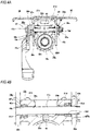
FIG. 11A is a partial side view of a steering column, depicting a seventh example of the embodiment, andFIG. 11B is a sectional view taken along a line B-B ofFIG. 11A . -
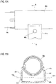
FIG. 12A is a view equivalent to the A-A section ofFIG. 1 in the unclamped state, depicting an eighth example of the embodiment, andFIG. 12B is a partially enlarged view ofFIG. 12A . -
FIG. 13A is a view equivalent to the A-A section ofFIG. 1 , depicting a switching state from the unclamped state to the clamped state, andFIG. 13B is a partially enlarged view ofFIG. 13A . -
FIG. 14A is a view equivalent to the A-A section ofFIG. 1 in the clamped state, depicting the eighth example of the embodiment, andFIG. 14B is a partially enlarged view ofFIG. 14A . -
FIG. 15 is a partial side view depicting an example of a steering device. -
FIG. 16 is a partial side view for illustrating a specific structure of a position adjustment device for steering wheel. -
FIG. 17 is a sectional view taken along a line C-C ofFIG. 16 . - A first example of an embodiment will be described with reference to
FIGS. 1 to 4 . In a steering device to which a vertical position adjustment device for steering wheel of the first example is applied, a steering shaft 5a is rotatably supported inside a cylindrical steering column 6a supported to a vehicle body, via a plurality of rolling bearings (not shown). The steering wheel 1 (refer toFIG. 15 ) is fixed to a rear end portion of the steering shaft 5a more protruding rearward than a rear end opening of the steering column 6a. - Also, an
electric motor 30, which is a power source for applying an auxiliary force to a front end portion of the steering column 6a, is supported to ahousing 10a fixed to the front end portion of the steering column 6a. Output torque (auxiliary force) of theelectric motor 30 is applied to the steering shaft 5a via a decelerator provided in thehousing 10a. Asupport pipe 31 is arranged in the width direction on an upper part of thehousing 10a. Thesupport pipe 31 is inserted by a bolt (not shown), which is a tilt shaft, so that thehousing 10a is swingably supported to a part of the vehicle body. - The steering device of the first example includes a tilt mechanism for adjusting a vertical position of the steering wheel 1 and a telescopic mechanism for adjusting a position in the front and rear direction, in correspondence to a physique and a driving posture of a driver.
- In order to configure the telescopic mechanism, the steering column 6a has such a configuration that a front end portion of an
outer column 18a arranged at the rear is loosely fitted to a rear end portion of aninner column 19a arranged at the front to be relatively displaced in the axial direction. In this way, an entire length of the steering device can be extended and shortened. Also, theouter column 18a is supported to asupport bracket 14a so that it can be moved in the front and rear direction. Also, the steering shaft 5a rotatably supported inside the steering column 6a has such a structure that aninner shaft 32 and anouter shaft 33 are combined by spline engagement or the like so as to transmit torque and to be expanded and contracted. Meanwhile, in the first example, theouter column 18a is entirely configured by die-casting a light alloy, for example. In the meantime, although not shown, the steering column 6a may have such a configuration that a front end portion of theinner column 19a arranged at the rear is loosely fitted to a rear end portion of theouter column 18a arranged at the front to be relatively displaced in the axial direction. - Also, in order to configure the tilt mechanism, the steering column 6a is supported to the vehicle body so that it can be swingably displaced about the tilt shaft mounted in the width direction, and the
outer column 18a is supported to thesupport bracket 14a so that it can be moved in the vertical direction. - Also, in order to support the
outer column 18a to thesupport bracket 14a to be moveable in the front and rear direction and in the vertical direction, aslit 20a extending in the axial direction is formed at an upper portion of a part close to the front end of theouter column 18a. Thereby, the part close to the front end of theouter column 18a is configured as a notched cylinder, so that an inner diameter of the part close to the front end can be elastically expanded and contracted. A pair of clampedplate parts displacement bracket 13a is provided at parts, which are an upper surface of the part close to the front end of theouter column 18a and are configured to clamp theslit 20a from both sides in the width direction. Also, both the clampedplate parts long holes long holes - The
support bracket 14a is made of a metal plate having sufficient stiffness such as steel, aluminum-based alloy or the like. Thesupport bracket 14a has anattachment plate part 34, and a pair ofsupport plate parts attachment plate part 34 is supported to the vehicle body in normal times. However, upon a collision accident, the attachment plate part is separated forward on the basis of a shock of a secondary collision, thereby allowing theouter column 18a to be displaced forward. To this end, a rear end edge of theattachment plate part 34 is formed with a pair of openednotches notches engagement capsules 36 fixed to the vehicle body by a fixing member such as a bolt, a stud or the like. - Both the
support plate parts attachment plate part 34. Both thesupport plate parts outer column 18a from both sides in the width direction. Also, portions of both thesupport plate parts long holes long holes adjustment rod 17a is inserted in the respectivelong holes long holes FIGS. 3 and4 , aguide member 42 made of an elastic material such as a rubber and having a rectangular section is provided in theslit 20a formed in theouter column 18a. An upper surface of theguide member 42 supports a lower surface of an intermediate part of theadjustment rod 17a in the width direction, from below. - Also, a non-drive-
side cam 27a, a drive-side cam 26a, and anadjustment lever 23a are arranged in corresponding order from thesupport plate part 22c between ahead 37 formed at one end portion (the left end portion inFIGS. 3 and4 ) of theadjustment rod 17a in the axial direction and one (the left inFIGS. 3 and4 )support plate part 22c of both thesupport plate parts side cam 27a and the drive-side cam 26a configure acam device 28a. Apressing plate 38 and athrust bearing 25a are arranged in corresponding order from thesupport plate part 22d between anut 24a screwed to a male screw portion formed at the other end portion (the right end portion inFIGS. 3 and4 ) of theadjustment rod 17a in the axial direction and the other (the right inFIG. 1 )support plate part 22d of both thesupport plate parts adjustment lever 23a, the drive-side cam 26a is rotated relative to the non-drive-side cam 27a, so that a width dimension (an axial dimension) of thecam device 28a can be expanded and contracted. - In the first example, the
pressing plate 38 and the non-drive-side cam 27a provided to the portions of theadjustment rod 17a, which protrude from outer surfaces of both thesupport plate parts cam device 28a corresponds to the expansion/contraction mechanism defined in the claims. - When adjusting a position of the steering wheel 1, the
adjustment lever 23a is rotated in a predetermine direction (in general, downward) to contract the width dimension of thecam device 28a and to expand a distance between the non-drive-side cam 27a and thepressing plate 38. As a result, a distance between the inner surfaces of both thesupport plate parts support plate parts plate parts support bracket 14a to thedisplacement bracket 13a is reduced or lost, theouter column 18a can be displaced within a range in which theadjustment rod 17a can move in both thelong holes long holes - In contrast, in order to keep the steering wheel 1 at a desired position, the
adjustment lever 23a is rotated in a direction (generally, upward) opposite to the predetermined direction to expand the width dimension of thecam device 28a and to shorten the distance between the non-drive-side cam27a and thepressing plate 38. As a result, the inner surfaces of both thesupport plate parts plate parts outer column 18a to which both the clampedplate parts outer column 18a and an outer peripheral surface of the rear end portion of theinner column 19a are strongly contacted. Then, the steering column 6a cannot be expanded or contracted, so that the position of the steering wheel 1 in the front and rear direction is fixed. As a result, the steering wheel 1 can be kept at a position after the adjustment. - The basic configuration of the steering device of the first example is as described above. Subsequently, features of the first example are described in detail.
- In the first example, in the clamped state, in order to improve the support rigidity impression of the steering wheel 1 in the vertical direction, the relation of the vertical gaps between the upper surfaces and lower surfaces of the inner surfaces of both the
long holes adjustment rod 17a is made to be different from the above-described conventional structure. To this end, in the first example, as shown inFIG. 2 , a central axis Oc of one (the left inFIG. 2 )long hole 16c for telescopic adjustment in the width direction, at which theadjustment lever 23a is arranged, of both thelong holes FIG. 2 )long hole 16d for telescopic adjustment in the width direction. Here, the central axis Oc extends perpendicularly to onesurface 47a of the clampedplate part 21c in the width direction, and the central axis Od extends perpendicularly to theother surface 47b of the clampedplate part 21d in the width direction. In the meantime, onesurface 47a of the clampedplate part 21c in the width direction and theother surface 47b of the clampedplate part 21d in the width direction extend in a direction perpendicular to the axial direction of the steering column 6 and perpendicular to the width direction of the vehicle body. That is, onesurface 47a of the clampedplate part 21c in the width direction and theother surface 47b of the clampedplate part 21d in the width direction extend in the vertical direction. - Also, in the first example, both the
long holes plate parts annular sleeves lower holes plate parts long holes long holes sleeves lower hole 39a in the width direction of both the telescopiclower holes lower hole 39b in the width direction. Also, both thesleeves sleeves -
FIG. 3 depicts an unclamped state where the width dimension of thecam device 28a is contracted and the force of clamping the clampedplate parts support plate parts FIG. 2 , a diameter of an inner surface of each of both thesleeves sleeve 40a in the width direction (thesleeve 40a positioned lower than thesleeve 40b) and extending in the direction perpendicular to onesurface 47a in the width direction of one clampedplate part 21c in the width direction is denoted with C, a straight line passing through the bottom of the inner surface of theother sleeve 40b in the width direction (thesleeve 40b positioned higher than thesleeve 40a) and extending in the direction perpendicular to theother surface 47b in the width direction of the other clampedplate part 21d in the width direction is denoted with D, and a vertical width between the straight lines C and D is denoted with B. Here, the diameter φA is smaller than the vertical width B (φ)A<B). Accordingly, in the unclamped state, due to a moment force based on a weight of theadjustment lever 23a supported to one end portion in the width direction, one end of theadjustment rod 17a in the width direction is tilted downward and the other end of theadjustment rod 17a in the width direction is tilted upward. For this reason, in the unclamped state, the lower surface of the inner surface of onelong hole 16c for telescopic adjustment in the width direction and the outer peripheral surface of theadjustment rod 17a are contacted, and the upper surface of the inner surface of the otherlong hole 16d for telescopic adjustment in the width direction and the outer peripheral surface of theadjustment rod 17a are contacted. Also, in this state, a relatively largevertical gap 41a exists between the upper surface of the inner surface of onelong hole 16c for telescopic adjustment in the width direction and the outer peripheral surface of theadjustment rod 17a, and a relatively largevertical gap 41b exists between the lower surface of the inner surface of the otherlong hole 16d for telescopic adjustment in the width direction and the outer peripheral surface of theadjustment rod 17a. In the first example, theadjustment rod 17a is tilted by the weight of theadjustment lever 23a. However, for example, theadjustment rod 17a may also be tilted using an elastic force of theguide member 42 arranged in theslit 20a. - In contrast, when the unclamped state as described above is switched to a clamped state, in which the width dimension of the
cam device 28a is expanded and the clampedplate parts support plate parts adjustment lever 23a, a state as shown inFIG. 4 is formed. That is, theadjustment rod 17a is caused to swing from the state shown inFIG. 3 , and is fixed with being arranged in a direction (the horizontal direction) perpendicular to both thesupport plate parts long hole 16c for telescopic adjustment in the width direction and the outer peripheral surface of theadjustment rod 17a are contacted, and the lower surface of the inner surface of the otherlong hole 16d for telescopic adjustment in the width direction and the outer peripheral surface of theadjustment rod 17a are contacted. Also, in this state, avertical gap 41c exists between the lower surface of the inner surface of onelong hole 16c for telescopic adjustment in the width direction and the outer peripheral surface of theadjustment rod 17a, and avertical gap 41d exists between the upper surface of the inner surface of the otherlong hole 16d for telescopic adjustment in the width direction and the outer peripheral surface of theadjustment rod 17a. - That is, in the first example, in the clamped state, the upper surface of the inner surface of one
long hole 16c for telescopic adjustment in the width direction is contacted to the outer peripheral surface of theadjustment rod 17a (the vertical gap between the upper surface and the outer peripheral surface becomes zero). Also, thevertical gap 41c exists between the lower surface of the inner surface of onelong hole 16c for telescopic adjustment in the width direction and the outer peripheral surface of theadjustment rod 17a. Also, the lower surface of the inner surface of the otherlong hole 16d for telescopic adjustment in the width direction is contacted to the outer peripheral surface of theadjustment rod 17a (the vertical gap between the lower surface and the outer peripheral surface becomes zero). Thevertical gap 41d exists between the upper surface of the inner surface of the otherlong hole 16d for telescopic adjustment in the width direction and the outer peripheral surface of theadjustment rod 17a. - According to the steering device of the first example configured as described above, it is possible to improve the support rigidity impression of the steering wheel 1 in the vertical direction, thereby improving the driver's steering feel.
- That is, in the first example, in the clamped state, the upper surface of the inner surface of one
long hole 16c for telescopic adjustment in the width direction and the outer peripheral surface of theadjustment rod 17a are contacted, the lower surface of the inner surface of the otherlong hole 16d for telescopic adjustment in the width direction and the outer peripheral surface of theadjustment rod 17a are contacted, and the contact positions to the outer peripheral surface of theadjustment rod 17a are on opposite sides with respect to the vertical direction in onelong hole 16c for telescopic adjustment in the width direction and the otherlong hole 16d for telescopic adjustment in the width direction. For this reason, as compared to the above-described conventional structure where the magnitude relation of the vertical gaps from the outer peripheral surface of the adjustment rod to the upper surface and lower surface of the inner surface is the same in one through-hole in the width direction and the other through-hole in the width direction, it is possible to suppress a distance (an amount of displacement) within which thesteering column 18a can be substantially displaced relative to theadjustment rod 17a in the vertical direction. Accordingly, it is possible to improve the support rigidity impression of the steering wheel 1 in the vertical direction, thereby improving the driver's steering feel. - Also, in the first example, in the unclamped state, one
long hole 16c for telescopic adjustment in the width direction is contacted only at the lower surface to the outer peripheral surface of theadjustment rod 17a, and the otherlong hole 16d for telescopic adjustment in the width direction is contacted only at the upper surface to the outer peripheral surface of theadjustment rod 17a. For this reason, it is possible to form the relatively largevertical gap 41a between the upper surface of the inner surface of onelong hole 16c for telescopic adjustment in the width direction and the outer peripheral surface of theadjustment rod 17a, and to form the relatively largevertical gap 41b between the lower surface of the inner surface of the otherlong hole 16d for telescopic adjustment in the width direction and the outer peripheral surface of theadjustment rod 17a. Accordingly, as described above, it is possible to suppress the substantial displacement of theouter column 18a relative to theadjustment rod 17a in the vertical direction in the clamped state, but it is possible to smoothly move theouter column 18a relative to theadjustment rod 17a in the front and rear direction in the unclamped state. As a result, it is possible to favorably perform the position adjusting operation of the steering wheel 1 in the front and rear direction. - Also, in the first example, when a secondary collision occurs and the forward and upward force is thus applied to the
outer column 18a, a part close to the other end of theadjustment rod 17a in the width direction is pressed by the lower surface of the inner surface of the otherlong hole 16d for telescopic adjustment in the width direction of both thelong holes adjustment rod 17a tends to be tilted (the distance between the non-drive-side cam 27a and thepressing plate 38 in the width direction tends to be narrowed), it is possible to strongly press both thesupport plate parts members displacement bracket 13a by thesupport bracket 14a. As a result, when the secondary collision occurs, it is possible to easily separate thesupport bracket 14a forward from the vehicle body, so that it is possible to sufficiently protect the driver. - A second example of the embodiment is described with reference to
FIG. 5 . A feature of the second example is that in the clamped state, the upper surface of the inner surface of one (the left inFIG. 5 )long hole 16c for telescopic adjustment in the width direction and the lower surface of the inner surface of the other (the right inFIG. 5 )long hole 16d for telescopic adjustment are contacted to the outer peripheral surface of theadjustment rod 17a with an interference, respectively. That is, in the second example, when theadjustment rod 17a is caused to swing in association with the switching from the unclamped state to the clamped state, the upper surface of the inner surface of thesleeve 40c configuring thelong hole 16c for telescopic adjustment and the lower surface of the inner surface of thesleeve 40d configuring thelong hole 16d for telescopic adjustment are respectively pressed by the outer peripheral surface of theadjustment rod 17a, so that both thesleeves - In the second example configured as described above, as compared to the first example of the embodiment, it is possible to make it difficult for the
outer column 18a to be displaced relative to theadjustment rod 17a in the vertical direction. Accordingly, it is possible to further improve the rigidity impression of the steering wheel 1 in the vertical direction. - The other configurations and operational effects are similar to the first example of the embodiment.
- A third example of the embodiment is described with reference to
FIG. 6 . A feature of the third example is that in the clamped state, vertical gaps are respectively provided between the upper surfaces and lower surfaces of the inner surfaces of thelong holes adjustment rod 17a. - That is, in the third example, when the
adjustment rod 17a is caused to swing in association with the switching from the unclamped state to the clamped state, a relatively largevertical gap 43a is provided between the lower surface of the inner surface of one (the left inFIG. 6 )long hole 16c for telescopic adjustment in the width direction and the outer peripheral surface of theadjustment rod 17a, and a relatively largevertical gap 43b having a vertical dimension smaller than thevertical gap 43a is provided between the upper surface and the outer peripheral surface of theadjustment rod 17a. Also, a relatively largevertical gap 43c is provided between the upper surface of the inner surface of the other (the right inFIG. 6 )long hole 16d for telescopic adjustment in the width direction and the outer peripheral surface of theadjustment rod 17a, and a relatively largevertical gap 43d having a vertical dimension smaller than thevertical gap 43c is provided between the lower surface and the outer peripheral surface of theadjustment rod 17a. - In the third example configured as described above, as compared to the first example of the embodiment, although the displaceable distance of the
outer column 18a relative to theadjustment rod 17a in the vertical direction increases, it is possible to sufficiently suppress the distance, as compared to the above-described conventional structure. Also, in the unclamped state, it is possible to more smoothly move theouter column 18a in the front and rear direction. - The other configurations and operational effects are similar to the first example of the embodiment.
- A fourth example of the embodiment is described with reference to
FIG. 7 . A feature of the fourth example is that the central axes Oc, Od of the pair oflong holes - That is, in the fourth example, a central axis of the telescopic
lower hole 39c formed in one clampedplate part 21c in the width direction and a central axis of the telescopiclower hole 39d formed in the other clampedplate part 21d in the width direction are made to coincide with each other with being arranged in the horizontal direction without deviating the same the vertical direction. In contrast, asleeve 40e to be mounted in one telescopiclower hole 39c in the width direction and asleeve 40f to be mounted in the other telescopiclower hole 39d in the width direction are made to be different in terms of thickness dimensions of an upper end portion and a lower end portion. Specifically, the thickness dimension (radial thickness) of the upper end portion is made greater for thesleeve 40e arranged at one side in the width direction than for thesleeve 40f arranged at the other side in the width direction, and the thickness dimension of the lower end portion is made smaller for thesleeve 40e arranged at one side in the width direction than for thesleeve 40f arranged at the other side in the width direction. Meanwhile, in the fourth example, in order to secure the above dimension relation, as both thesleeves sleeves lower holes - In the fourth example configured as described above, since it is possible to form one telescopic
lower hole 39c in the width direction and the other telescopiclower hole 39d in the width direction on the same axis, it is possible to reduce the processing cost, as compared to the first example of the embodiment. - The other configurations and operational effects are similar to the first example of the embodiment.
- A fifth example of the embodiment is described with reference to
FIGS. 8 and9 . A feature of the fifth example is that in the unclamped state, theadjustment rod 17a is tilted in the opposite direction to the first example of the embodiment. - That is, in the fifth example, a central axis Of of the other (the right in
FIG. 8 )long hole 16f for telescopic adjustment in the width direction of a pair oflong holes FIG. 8 )long hole 16e for telescopic adjustment in the width direction. To this end, in the fifth example, the other telescopiclower hole 39f in the width direction is formed lower than one telescopiclower hole 39e in the width direction. Theannular sleeves lower holes long holes - In the fifth example configured as described above, in the unclamped state, as shown in
FIG. 8 , one end of theadjustment rod 17a in the width direction is tilted upward and the other end of theadjustment rod 17a in the width direction is tilted downward. For this reason, in the unclamped state, the upper surface of the inner surface of onelong hole 16e for telescopic adjustment in the width direction and the outer peripheral surface of theadjustment rod 17a are contacted, and the lower surface of the inner surface of the otherlong hole 16f for telescopic adjustment in the width direction and the outer peripheral surface of theadjustment rod 17a are contacted. Also, in this state, a relatively largevertical gap 44a exists between the lower surface of the inner surface of onelong hole 16e for telescopic adjustment in the width direction and the outer peripheral surface of theadjustment rod 17a, and a relatively largevertical gap 44b exists between the upper surface of the inner surface of the otherlong hole 16f for telescopic adjustment in the width direction and the outer peripheral surface of theadjustment rod 17a. - In contrast, when the unclamped state is switched to the clamped state, the
adjustment rod 17a is caused to swing from the state shown inFIG. 8 , and is fixed with being arranged in the direction (the horizontal direction) perpendicular to both thesupport plate parts long hole 16e for telescopic adjustment in the width direction and the outer peripheral surface of theadjustment rod 17a are contacted, and the upper surface of the inner surface of the otherlong hole 16f for telescopic adjustment in the width direction and the outer peripheral surface of theadjustment rod 17a are contacted. Also, in this state, avertical gap 44c exists between the upper surface of the inner surface of onelong hole 16e for telescopic adjustment in the width direction and the outer peripheral surface of theadjustment rod 17a, and avertical gap 44d exists between the lower surface of the inner surface of the otherlong hole 16f for telescopic adjustment in the width direction and the outer peripheral surface of theadjustment rod 17a. - The other configurations and operational effects are similar to the first example of the embodiment.
- A sixth example of the embodiment is described with reference to
FIG. 10 . A feature of the sixth example is that the relation of the vertical gaps between the upper surfaces and lower surfaces of the inner surfaces of a pair oflong holes adjustment rod 17a (refer toFIGS. 3 and4 , and the like) are made to be different from the above-described conventional structure, without causing central axes Og, Oh of both thelong holes - That is, in the sixth example, the central axis Og of one
long hole 16g for telescopic adjustment in the width direction of both thelong holes long hole 16h for telescopic adjustment in the width direction are made to coincide with each other, and are inclined by an angle of α in the vertical direction with respect to the horizontal direction. To this end, one telescopiclower hole 39g in the width direction and the other telescopiclower hole 39h in the width direction are formed on the same axis with being inclined by the angle of α with respect to the horizontal direction. The telescopiclower holes annular sleeves long holes FIG. 10 , diameters of inner surfaces of thesleeves sleeve 40g in the width direction and extending in the direction perpendicular to onesurface 47a in the width direction of one clampedplate part 21c in the width direction is denoted with G, a straight line passing through the bottom of the other end portion in the width direction of the inner surface of theother sleeve 40h in the width direction and extending in the direction perpendicular to theother surface 47b in the width direction of the other clampedplate part 21d in the width direction is denoted with H, and a vertical width between the straight lines G and H is denoted with F. Here, the diameter φE is smaller than the vertical width F (φE<F). - In the sixth example configured as described above, in the unclamped state, due to the moment force based on the weight of the
adjustment lever 23a (refer toFIGS. 3 and4 , and the like) supported to one end portion of theadjustment rod 17a in the width direction, one end of theadjustment rod 17a in the width direction is tilted downward and the other end of theadjustment rod 17a in the width direction is tilted upward. For this reason, in the unclamped state, the lower surface of the inner surface of onelong hole 16g for telescopic adjustment in the width direction and the outer peripheral surface of theadjustment rod 17a are contacted, and the upper surface of the inner surface of the otherlong hole 16h for telescopic adjustment in the width direction and the outer peripheral surface of theadjustment rod 17a are contacted. Also, in this state, a relatively large vertical gap exists between the upper surface of the inner surface of onelong hole 16g for telescopic adjustment in the width direction and the outer peripheral surface of theadjustment rod 17a, and a relatively large vertical gap exists between the lower surface of the inner surface of the otherlong hole 16h for telescopic adjustment in the width direction and the outer peripheral surface of theadjustment rod 17a. - In contrast, when the unclamped state is switched to the clamped state, the
adjustment rod 17a is fixed with being arranged in the direction perpendicular to thesupport plate parts FIGS. 3 and4 , and the like). In this clamped state, the upper surface of the inner surface of onelong hole 16g for telescopic adjustment in the width direction and the outer peripheral surface of theadjustment rod 17a are contacted, and the lower surface of the inner surface of the otherlong hole 16h for telescopic adjustment in the width direction and the outer peripheral surface of theadjustment rod 17a are contacted. Also, in this state, a vertical gap exists between the lower surface of the inner surface of onelong hole 16g for telescopic adjustment in the width direction and the outer peripheral surface of theadjustment rod 17a, and a vertical gap exists between the upper surface of the inner surface of the otherlong hole 16h for telescopic adjustment in the width direction and the outer peripheral surface of theadjustment rod 17a. - In the sixth example configured as described above, since both the telescopic
lower holes lower hole - The other configurations and operational effects are similar to the first example of the embodiment.
- A seventh example of the embodiment is described with reference to
FIG. 11 . A feature of the seventh example is that only the tilt mechanism for adjusting the vertical position is provided without the telescopic mechanism for adjusting the position of the steering wheel 1 (refer toFIG. 15 ) in the front and rear direction. - For this reason, in the seventh example, a pair of clamped
plate parts outer column 18a is formed with simplecircular holes circular hole 45a in the width direction is arranged to deviate more upward than a central axis O45b of the othercircular hole 45b in the width direction. - Also in the seventh example configured as described above, like the first example of the embodiment, in the clamped state, it is possible to suppress the distance within which the
outer column 18a can be substantially displaced in the vertical direction relative to theadjustment rod 17a (refer toFIGS. 3 and4 , and the like) inserted in both thecircular holes - The other configurations and operational effects are similar to the first example of the embodiment.
- An eighth example of the embodiment is described with reference to
FIGS. 12 to 14 . In the eighth example, a pair ofsupport plate parts support bracket 14b is made to have different bending rigidity in the width direction. That is, a plate thickness of onesupport plate part 22e in the width direction is made greater than a plate thickness of the othersupport plate part 22f in the width direction, so that the bending rigidity of onesupport plate part 22e in the width direction is made higher than the bending rigidity of the othersupport plate part 22f in the width direction. Also, a central axis Oi of onelong hole 16i for telescopic adjustment in the width direction, in which thesupport plate part 22e having higher bending rigidity is arranged, of a pair oflong holes outer column 18a than a central axis Oj of the otherlong hole 16j for telescopic adjustment in the width direction. In the eighth example, the lower surface of the outer peripheral surface of theadjustment rod 17a is elastically pressed upward by aguide member 42a made of an elastic material and provided in theslit 20a of theouter column 18a. - In the eighth example configured as described above, the
adjustment rod 17a is pushed upward by the pressing force of theguide member 42a. For this reason, in the unclamped state shown inFIG. 12 , the upper surface of the inner surface of onelong hole 16i for telescopic adjustment in the width direction and the outer peripheral surface of theadjustment rod 17a are contacted, and the upper surface of the inner surface of the otherlong hole 16j for telescopic adjustment in the width direction and the outer peripheral surface of theadjustment rod 17a are contacted. Also, in this state, a relatively largevertical gap 46a exists between the lower surface of the inner surface of onelong hole 16i for telescopic adjustment in the width direction and the outer peripheral surface of theadjustment rod 17a, and a relatively largevertical gap 46b exists between the lower surface of the inner surface of the otherlong hole 16j for telescopic adjustment in the width direction and the outer peripheral surface of theadjustment rod 17a. - In contrast, when the unclamped state as described above is switched to the clamped state, the
adjustment rod 17a is caused to swing in the horizontal direction about one part in the width direction at which thesupport plate part 22e having higher bending rigidity is arranged, in order ofFIG. 12 →FIG. 13 →FIG. 14 . Then, in the clamped state as shown inFIG. 14 , the lower surface of the inner surface of the otherlong hole 16j for telescopic adjustment in the width direction is contacted to the outer peripheral surface of theadjustment rod 17a with the upper surface of the inner surface of onelong hole 16i for telescopic adjustment in the width direction being in contact with the outer peripheral surface of theadjustment rod 17a. Also, in this state, thevertical gap 46a exists between the lower surface of the inner surface of onelong hole 16i for telescopic adjustment in the width direction and the outer peripheral surface of theadjustment rod 17a, and avertical gap 46c exists between the upper surface of the inner surface of the otherlong hole 16j for telescopic adjustment in the width direction and the outer peripheral surface of theadjustment rod 17a. - In the eighth example configured as described above, when the unclamped state is switched to the clamped state, the
adjustment rod 17a can be caused to swing in the horizontal direction about one part in the width direction at which thesupport plate part 22e having higher bending rigidity is arranged. Accordingly, one end portion in the width direction of the outer peripheral surface of theadjustment rod 17a can be kept to be in contact with the upper surface of the inner surface of onelong hole 16i for telescopic adjustment in the width direction. For this reason, upon the switching to the clamped state, it is possible to prevent the outer peripheral surface of theadjustment rod 17a from strongly contacting the inner surface of thelong hole 16i for telescopic adjustment (the inner surface of thesleeve 40a). - The other configurations and operational effects are similar to the first example of the embodiment.
- The subject application is based on Japanese Patent Application No.
2015-236862 filed on December 3, 2015 - When implementing the present invention, the deviation amounts and deviation directions of the pair of through-holes (the long holes for telescopic adjustment) with respect to the vertical direction and the inclination angle (the sixth example of the embodiment) of the central axis relative to the horizontal direction are implemented without being limited to the respective examples of the embodiment. Also, the respective examples of the embodiment can be implemented with being appropriately combined.
-
- 1: steering wheel
- 2: steering gear unit
- 3: input shaft
- 4: tie-rod
- 5, 5a: steering shaft
- 6, 6a: steering column
- 7: universal joint
- 8: intermediate shaft
- 9: universal joint
- 10, 10a: housing
- 11: vehicle body
- 12: tilt shaft
- 13: displacement bracket
- 14, 14a, 14b: support bracket
- 15a, 15b: long hole for tilt adjustment
- 16a to 16j: long hole for telescopic adjustment
- 17, 17a: adjustment rod
- 18, 18a: outer column
- 19, 19a: inner column
- 20, 20a: slit
- 21a to 21f: clamped plate part
- 22a to 22f: support plate part
- 23, 23a: adjustment lever
- 24, 24a: nut
- 25, 25a: thrust bearing
- 26, 26a: drive-side cam
- 27, 27a: non-drive-side cam
- 28, 28a: cam device
- 29a to 29d: vertical gap
- 30: electric motor
- 31: support pipe
- 32: inner shaft
- 33: outer shaft
- 34: attachment plate part
- 35: notch
- 36: engagement capsule
- 37: head
- 38: pressing plate
- 39a to 39f: telescopic lower hole
- 40a to 40f: sleeve
- 41a, 41b: vertical gap
- 42, 42a: guide member
- 43a to 43d: vertical gap
- 44a to 44d: vertical gap
- 45a, 45b: circular hole
- 46a to 46c: vertical gap
- 47a: one surface in the width direction
- 47b: the other surface in the width direction
Claims (9)
- A vertical position adjustment device for steering wheel comprising:a pair of clamped plate parts provided at parts of a steering column with being spaced from each other in a width direction;a pair of through-holes formed to penetrate both the clamped plate parts in the width direction;a pair of support plate parts provided at parts of a support bracket supported to a vehicle body with clamping both the clamped plate parts from both sides in the width direction;a pair of long holes for tilt adjustment which are respectively long in a vertical direction, and are formed to penetrate both the support plate parts in the width direction;an adjustment rod provided to be inserted in both the through-holes and both the long holes for tilt adjustment in the width direction;a pair of pressing parts provided at parts, which protrude from outer surfaces of both the support plate parts, of the adjustment rod, andan expansion/contraction mechanism configured to expand and reduce an interval between both the pressing parts, whereinin a clamped state where the interval between both the pressing parts is reduced and both the clamped plate parts are clamped by both the support plate parts, vertical distances from an outer peripheral surface of the adjustment rod to an upper surface and a lower surface of an inner surface of one through-hole of both the through-holes are different, vertical distances from the outer peripheral surface of the adjustment rod to an upper surface and a lower surface of an inner surface of the other through-hole of both the through-holes are different, and sides, where the vertical distance from the outer peripheral surface of the adjustment rod to the inner surface is smaller, are on opposite sides with respect to the vertical direction in one through-hole and the other through-hole.
- The vertical position adjustment device for steering wheel according to claim 1, wherein
in an unclamped state where the interval between both the pressing parts is expanded and a force of clamping both the clamped plate parts by both the support plate parts is released, the inner surface of one through-hole of both the through-holes and the inner surface of the other through-hole are contacted to the outer peripheral surface of the adjustment rod at only one side in the vertical direction, respectively. - The vertical position adjustment device for steering wheel according to claim 1 or 2, wherein
a central axis of one through-hole and a central axis of the other through-hole deviate from each other in the vertical direction. - The vertical position adjustment device for steering wheel according to any one of claims 1 to 3, wherein
each of the through-holes is configured by an inner surface of an annular sleeve, which is made of an elastic material and to be mounted in a lower hole formed to each of the clamped plate parts. - The vertical position adjustment device for steering wheel according to claim 4, wherein
a central axis of one lower hole formed to one clamped plate part of both the clamped plate parts and a central axis of the other lower hole formed to the other clamped plate part deviate from each other in the vertical direction. - The vertical position adjustment device for steering wheel according to claim 4, wherein
a central axis of one lower hole formed to one clamped plate part of both the clamped plate parts and a central axis of the other lower hole formed to the other clamped plate part coincide with each other, and
a central axis of one through-hole configured by the inner surface of one sleeve to be mounted in one lower hole and a central axis of the other through-hole configured by the inner surface of the other sleeve to be mounted in the other lower hole deviate from each other in the vertical direction. - The vertical position adjustment device for steering wheel according to any one of claims 4 to 6, wherein
in the clamped state, the inner surface of any one of both the through-holes and the outer peripheral surface of the adjustment rod are contacted with an interference in the vertical direction. - The vertical position adjustment device for steering wheel according to any one of claims 1 to 6, wherein
in the clamped state, vertical gaps having different sizes are respectively provided between both the upper and lower surfaces of the inner surface of one through-hole and the outer peripheral surface of the adjustment rod, and vertical gaps having different sizes are respectively provided between both the upper and lower surfaces of the inner surface of the other through-hole and the outer peripheral surface of the adjustment rod. - The vertical position adjustment device for steering wheel according to any one of claims 3 to 8, wherein
bending rigidity of one support plate part of both the support plate parts is higher than bending rigidity of the other support plate part,
the central axis of the through-hole, which is arranged at one support plate part-side in the width direction, of both the through-holes is arranged to be closer to the steering column in the vertical direction than the central axis of the other through-hole, and
the outer peripheral surface of the adjustment rod is urged toward a surface, which is distant from the steering column in the vertical direction, of the upper and lower surfaces of the inner surface of the through-hole arranged in one support plate part-side, by an elastic member.
Applications Claiming Priority (2)
| Application Number | Priority Date | Filing Date | Title |
|---|---|---|---|
| JP2015236862 | 2015-12-03 | ||
| PCT/JP2016/085878 WO2017094877A1 (en) | 2015-12-03 | 2016-12-02 | Vertical position adjustment device for steering wheel |
Publications (3)
| Publication Number | Publication Date |
|---|---|
| EP3366545A1 true EP3366545A1 (en) | 2018-08-29 |
| EP3366545A4 EP3366545A4 (en) | 2018-10-31 |
| EP3366545B1 EP3366545B1 (en) | 2020-03-25 |
Family
ID=58797517
Family Applications (1)
| Application Number | Title | Priority Date | Filing Date |
|---|---|---|---|
| EP16870812.1A Active EP3366545B1 (en) | 2015-12-03 | 2016-12-02 | Vertical position adjustment device for steering wheel |
Country Status (5)
| Country | Link |
|---|---|
| US (1) | US10597065B2 (en) |
| EP (1) | EP3366545B1 (en) |
| JP (1) | JP6460263B2 (en) |
| CN (1) | CN108290599B (en) |
| WO (1) | WO2017094877A1 (en) |
Families Citing this family (3)
| Publication number | Priority date | Publication date | Assignee | Title |
|---|---|---|---|---|
| CN108608992B (en) * | 2018-07-19 | 2023-09-12 | 福州大学 | A multifunctional vehicle control system based on fingerprint recognition and its working method |
| WO2020085411A1 (en) * | 2018-10-24 | 2020-04-30 | 日本精工株式会社 | Steering column device |
| JP7759826B2 (en) * | 2022-03-17 | 2025-10-24 | 株式会社山田製作所 | Steering device |
Family Cites Families (17)
| Publication number | Priority date | Publication date | Assignee | Title |
|---|---|---|---|---|
| FR2579159B1 (en) | 1985-03-25 | 1987-06-26 | Nacam | DEVICE FOR ADJUSTING A STEERING COLUMN OF A MOTOR VEHICLE PROVIDED WITH KNEE LOCKING MEANS |
| JPS6332962U (en) | 1986-08-20 | 1988-03-03 | ||
| FR2696404B1 (en) | 1992-10-06 | 1994-12-23 | Ecia Equip Composants Ind Auto | Device for locking in position an adjustable steering column, in particular for a motor vehicle, and column assembly comprising such a device. |
| JP2009073378A (en) | 2007-09-21 | 2009-04-09 | Nsk Ltd | Position adjustment type steering device |
| JP2009227181A (en) | 2008-03-25 | 2009-10-08 | Nsk Ltd | Steering device |
| EP2105369A2 (en) | 2008-03-25 | 2009-09-30 | NSK Ltd. | Steering apparatus |
| JP5392114B2 (en) | 2010-01-28 | 2014-01-22 | 日本精工株式会社 | Steering device |
| EP2765057B1 (en) | 2011-09-29 | 2017-05-17 | NSK Ltd. | Telescopic steering device |
| DE102011056674B3 (en) | 2011-10-19 | 2012-12-06 | Thyssenkrupp Presta Aktiengesellschaft | Steering column for motor car, has clamping bolt penetrating through side walls of bracket part, and penetrating bearing part into bearing part bead and steering shaft bearing unit in steering shaft bearing unit bead |
| WO2013094305A1 (en) | 2011-12-20 | 2013-06-27 | 日本精工株式会社 | Steering device |
| GB201208791D0 (en) | 2012-05-18 | 2012-07-04 | Trw Ltd | Steering column assembly |
| EP2915719B1 (en) * | 2012-11-02 | 2018-07-11 | NSK Ltd. | Tilt-type steering device |
| CN104254474B (en) * | 2013-02-13 | 2017-03-29 | 日本精工株式会社 | Column jacket and steering axle device |
| JP6369046B2 (en) | 2014-02-21 | 2018-08-08 | 日本精工株式会社 | Steering device |
| WO2016114034A1 (en) * | 2015-01-13 | 2016-07-21 | 日本精工株式会社 | Steering device |
| JPWO2017082325A1 (en) * | 2015-11-12 | 2018-09-27 | 日本精工株式会社 | Steering device and method for assembling steering device |
| JP6921720B2 (en) * | 2017-11-17 | 2021-08-18 | 株式会社山田製作所 | Steering device |
-
2016
- 2016-12-02 CN CN201680070197.3A patent/CN108290599B/en active Active
- 2016-12-02 US US15/774,910 patent/US10597065B2/en active Active
- 2016-12-02 WO PCT/JP2016/085878 patent/WO2017094877A1/en not_active Ceased
- 2016-12-02 EP EP16870812.1A patent/EP3366545B1/en active Active
- 2016-12-02 JP JP2017554196A patent/JP6460263B2/en active Active
Also Published As
| Publication number | Publication date |
|---|---|
| US20180327018A1 (en) | 2018-11-15 |
| CN108290599B (en) | 2020-09-15 |
| CN108290599A (en) | 2018-07-17 |
| JP6460263B2 (en) | 2019-01-30 |
| EP3366545B1 (en) | 2020-03-25 |
| WO2017094877A1 (en) | 2017-06-08 |
| JPWO2017094877A1 (en) | 2018-04-26 |
| US10597065B2 (en) | 2020-03-24 |
| EP3366545A4 (en) | 2018-10-31 |
Similar Documents
| Publication | Publication Date | Title |
|---|---|---|
| EP3045377B1 (en) | Position adjustment device for steering wheel | |
| CN102971198B (en) | Steering device | |
| JP5050550B2 (en) | Steering device | |
| EP3000690B1 (en) | Position adjusting-type steering device | |
| EP3395647B1 (en) | Steering apparatus | |
| EP2765057B1 (en) | Telescopic steering device | |
| US11148703B2 (en) | Support bracket for steering apparatus and steering apparatus | |
| EP3323694B1 (en) | Adjustment lever assembly, and position adjustment device for steering wheel | |
| EP2915719B1 (en) | Tilt-type steering device | |
| EP3124353B1 (en) | Position adjustment device for steering wheel | |
| CN107614357A (en) | Telescopic steering column and steering gear | |
| US11440579B2 (en) | Steering column device | |
| EP3366545B1 (en) | Vertical position adjustment device for steering wheel | |
| EP3130525B1 (en) | Steering wheel position adjustment device | |
| EP3489111A1 (en) | Steering device | |
| EP2889203A1 (en) | Telescopic steering device | |
| EP3260350A1 (en) | Steering apparatus | |
| EP3421326A1 (en) | Position adjustment device for steering wheel | |
| EP3318466A1 (en) | Position adjustment device for steering wheel | |
| JP2018202962A (en) | Device of adjusting vertical position of steering wheel | |
| JP2008114788A (en) | Steering device | |
| JP5470711B2 (en) | Steering device | |
| US11447170B2 (en) | Steering column and steering device | |
| US11511788B2 (en) | Steering column and steering device | |
| JP6406020B2 (en) | Steering wheel position adjustment device |
Legal Events
| Date | Code | Title | Description |
|---|---|---|---|
| STAA | Information on the status of an ep patent application or granted ep patent |
Free format text: STATUS: THE INTERNATIONAL PUBLICATION HAS BEEN MADE |
|
| PUAI | Public reference made under article 153(3) epc to a published international application that has entered the european phase |
Free format text: ORIGINAL CODE: 0009012 |
|
| STAA | Information on the status of an ep patent application or granted ep patent |
Free format text: STATUS: REQUEST FOR EXAMINATION WAS MADE |
|
| 17P | Request for examination filed |
Effective date: 20180524 |
|
| AK | Designated contracting states |
Kind code of ref document: A1 Designated state(s): AL AT BE BG CH CY CZ DE DK EE ES FI FR GB GR HR HU IE IS IT LI LT LU LV MC MK MT NL NO PL PT RO RS SE SI SK SM TR |
|
| AX | Request for extension of the european patent |
Extension state: BA ME |
|
| A4 | Supplementary search report drawn up and despatched |
Effective date: 20181004 |
|
| RIC1 | Information provided on ipc code assigned before grant |
Ipc: B62D 1/189 20060101ALI20180927BHEP Ipc: B62D 1/184 20060101AFI20180927BHEP |
|
| DAV | Request for validation of the european patent (deleted) | ||
| DAX | Request for extension of the european patent (deleted) | ||
| GRAP | Despatch of communication of intention to grant a patent |
Free format text: ORIGINAL CODE: EPIDOSNIGR1 |
|
| STAA | Information on the status of an ep patent application or granted ep patent |
Free format text: STATUS: GRANT OF PATENT IS INTENDED |
|
| INTG | Intention to grant announced |
Effective date: 20191129 |
|
| GRAS | Grant fee paid |
Free format text: ORIGINAL CODE: EPIDOSNIGR3 |
|
| GRAA | (expected) grant |
Free format text: ORIGINAL CODE: 0009210 |
|
| STAA | Information on the status of an ep patent application or granted ep patent |
Free format text: STATUS: THE PATENT HAS BEEN GRANTED |
|
| AK | Designated contracting states |
Kind code of ref document: B1 Designated state(s): DE FR GB |
|
| RBV | Designated contracting states (corrected) |
Designated state(s): DE FR GB |
|
| REG | Reference to a national code |
Ref country code: GB Ref legal event code: FG4D |
|
| REG | Reference to a national code |
Ref country code: DE Ref legal event code: R096 Ref document number: 602016032753 Country of ref document: DE |
|
| REG | Reference to a national code |
Ref country code: DE Ref legal event code: R097 Ref document number: 602016032753 Country of ref document: DE |
|
| PLBE | No opposition filed within time limit |
Free format text: ORIGINAL CODE: 0009261 |
|
| STAA | Information on the status of an ep patent application or granted ep patent |
Free format text: STATUS: NO OPPOSITION FILED WITHIN TIME LIMIT |
|
| 26N | No opposition filed |
Effective date: 20210112 |
|
| GBPC | Gb: european patent ceased through non-payment of renewal fee |
Effective date: 20201202 |
|
| PG25 | Lapsed in a contracting state [announced via postgrant information from national office to epo] |
Ref country code: FR Free format text: LAPSE BECAUSE OF NON-PAYMENT OF DUE FEES Effective date: 20201231 |
|
| PG25 | Lapsed in a contracting state [announced via postgrant information from national office to epo] |
Ref country code: GB Free format text: LAPSE BECAUSE OF NON-PAYMENT OF DUE FEES Effective date: 20201202 |
|
| PGFP | Annual fee paid to national office [announced via postgrant information from national office to epo] |
Ref country code: DE Payment date: 20241029 Year of fee payment: 9 |