EP3366100B1 - Robotic garden tool - Google Patents
Robotic garden tool Download PDFInfo
- Publication number
- EP3366100B1 EP3366100B1 EP18152871.2A EP18152871A EP3366100B1 EP 3366100 B1 EP3366100 B1 EP 3366100B1 EP 18152871 A EP18152871 A EP 18152871A EP 3366100 B1 EP3366100 B1 EP 3366100B1
- Authority
- EP
- European Patent Office
- Prior art keywords
- garden tool
- robotic garden
- positioning device
- robotic
- working area
- Prior art date
- Legal status (The legal status is an assumption and is not a legal conclusion. Google has not performed a legal analysis and makes no representation as to the accuracy of the status listed.)
- Active
Links
- 230000001788 irregular Effects 0.000 claims description 5
- 238000000034 method Methods 0.000 description 5
- 244000025254 Cannabis sativa Species 0.000 description 2
- 238000010586 diagram Methods 0.000 description 2
- 230000010354 integration Effects 0.000 description 2
- 238000011022 operating instruction Methods 0.000 description 2
- 238000004441 surface measurement Methods 0.000 description 2
Images


Classifications
-
- A—HUMAN NECESSITIES
- A01—AGRICULTURE; FORESTRY; ANIMAL HUSBANDRY; HUNTING; TRAPPING; FISHING
- A01D—HARVESTING; MOWING
- A01D34/00—Mowers; Mowing apparatus of harvesters
- A01D34/006—Control or measuring arrangements
- A01D34/008—Control or measuring arrangements for automated or remotely controlled operation
-
- G—PHYSICS
- G05—CONTROLLING; REGULATING
- G05D—SYSTEMS FOR CONTROLLING OR REGULATING NON-ELECTRIC VARIABLES
- G05D1/00—Control of position, course, altitude or attitude of land, water, air or space vehicles, e.g. using automatic pilots
- G05D1/02—Control of position or course in two dimensions
- G05D1/021—Control of position or course in two dimensions specially adapted to land vehicles
- G05D1/0259—Control of position or course in two dimensions specially adapted to land vehicles using magnetic or electromagnetic means
- G05D1/0265—Control of position or course in two dimensions specially adapted to land vehicles using magnetic or electromagnetic means using buried wires
-
- G—PHYSICS
- G05—CONTROLLING; REGULATING
- G05D—SYSTEMS FOR CONTROLLING OR REGULATING NON-ELECTRIC VARIABLES
- G05D1/00—Control of position, course, altitude or attitude of land, water, air or space vehicles, e.g. using automatic pilots
- G05D1/02—Control of position or course in two dimensions
- G05D1/021—Control of position or course in two dimensions specially adapted to land vehicles
- G05D1/0276—Control of position or course in two dimensions specially adapted to land vehicles using signals provided by a source external to the vehicle
- G05D1/0278—Control of position or course in two dimensions specially adapted to land vehicles using signals provided by a source external to the vehicle using satellite positioning signals, e.g. GPS
Definitions
- the present invention relates to a robotic garden tool.
- the robotic garden tools such as, but not limited to robotic lawnmowers are widely used for grass cutting applications in a lawn. As these robotic garden tools are autonomous, they have to navigate and keep a track of the areas they have performed operations upon. This is particularly important for the case in which the area to be mowed is very large. If the robotic garden tool does not keep the track of the locations it has performed operations upon and which are the remaining locations, then it may take long time to complete the operation in the whole area.
- GPS Global Positioning System
- the GPS system may provide accurate data as to where the robotic garden tool is, the areas it has performed operations upon, areas remaining, etc. But the problem associated with such system is that it needs expensive GPS trans-receiver to be mounted on the robotic garden tool. Also, the interconnection between the GPS module and the other parts of the robotic garden tool adds to the complexity and the cost of the whole system. Further, if the contact to the GPS system is lost the robotic garden tool may not know its working area limits and might go off boundary.
- EP1933467A2 and EP1886549A1 discloses, respectively, a robotic lawnmower configured to operate within an area defined by a boundary wire.
- the robotic lawnmower has a GPS device for enhanced navigation.
- the objective is to provide a method and a system for navigating a robotic garden tool without complex integration.
- the objective is achieved according to the robotic garden tool described in claim 1.
- control unit may be adapted to generate a map based on the coordinates from the low-accuracy positioning device and the one or more signals received from the signal source.
- control unit may further be adapted to generate one or more commands based at least in part on the location of the robotic garden tool.
- the low-accuracy positioning device may be a standard GPS device.
- the accuracy of the low-accuracy positioning device is less than ⁇ 0.1m.
- FIG. 1 illustrates a block diagram of a system 100 , according to an embodiment of the present invention.
- the system 100 may be embodied in a robotic garden tool for navigating the robotic garden tool around the lawn to be mowed.
- the robotic garden tool may be adapted to operate in a working area of the lawn in an irregular pattern.
- the robotic garden tool may be a robotic lawn mower.
- the system 100 may also be embodied in any another equipment, such as, but not limited to an automated vacuum cleaner or any other autonomous robotic tool without departing from the scope of the present invention.
- the working area of the lawn may be divided into various subareas. Further, in an embodiment of the present invention, the working area of the lawn may be defined by boundaries. In an embodiment of the present invention the boundary may define the working area by means of physical fences, fixed objects, surface determination, a boundary wire and the like. In various embodiments of the present invention, the boundaries may be identified based on one or more signals 102 generated from a signal source 104. In an embodiment of the present invention, the signal source 104 may be a wire, in particular a boundary wire spread along the perimeter of the working area in the lawn.
- the robotic garden tool includes a sensor unit 106 , which is adapted to detect the one or more signals 102 from the signal source 104, as well as other physical objects like fences or fixed objects present in the lawn.
- the one or more signals 102 include magnetic field signals or electrical current signals from the boundary wire.
- the sensor unit 106 further includes one or more sensors, such as, but not limited to, a magnetic field sensor, a current sensor, proximity sensor or photoelectric sensor.
- the sensor unit 106 is positioned at a front portion of the robotic garden tool. In another embodiment of the present invention, the sensors may be positioned at any suitable location on the robotic garden tool.
- the sensor unit 106 converts the one or more signals 102 into equivalent electrical signals. Further, the sensor unit 106 provides the converted equivalent electric signals to a control unit 108 , provided in the robotic garden tool, for further processing.
- the system 100 includes a low-accuracy positioning device 110 (herein after referred to as positioning device 110 ) in the robotic garden tool.
- the positioning device 110 may be a standard low-accuracy Global Positioning System (GPS).
- GPS Global Positioning System
- the positioning device 110 may be a Local Positioning System.
- the positioning device 110 may be any device which is capable of providing location based information to the robotic garden tool.
- the accuracy of the positioning device 110 may be ⁇ 10m.
- the accuracy of the positioning device 110 may be ⁇ 3m.
- the accuracy of the positioning device 110 may be ⁇ 1m.
- the accuracy of the positioning device 110 may be ⁇ 0.1m.
- the positioning device 110 is adapted to provide position co-ordinates of the working area, which is divided into various subareas, to the control unit 108 .
- the position co-ordinates define the various subareas within the working area.
- the positioning device 110 is also adapted to provide coordinates for an approximate position of the robotic garden tool to the control unit 108 .
- control unit 108 further includes a memory means 112 and a processing means 114 .
- the control unit 108 stores the position co-ordinates of the subareas, provided by the positioning device 110 , and the converted equivalent electric signals, provided by the sensor unit 106 , in the memory means 112 and/or provide them directly to the processing unit 114 .
- the memory means 112 may be a Random Access Memory (RAM), Read Only Memory (ROM), flash memory or any suitable storage equipment.
- the memory means 112 may include various modules for storing operating instructions and other software of the control unit 108 .
- the operating instructions may be a set of computer executable instructions for controlling the overall operations of the control unit 108 .
- the memory means 112 also stores a database of parameters required to send a command to the robotic garden tool based on one or more signals received from the sensor unit 106 and the positioning device 110 .
- the parameters may also include geometry of the lawn or field, strength of the detected signals, types of detected signals etc.
- the one or more parameters from the memory means 112 are communicated to the processing means 114 for further processing.
- the processing means 114 performs all the computations required to navigate robotic garden tool in different areas of the lawn.
- the processing means 114 includes an input/output (I/O) interface (not shown), which is operable for receiving the parameters and the computer executable instructions from the memory means 112 .
- the processing means 114 also obtains the converted electrical signals from the sensor unit 106 through the I/O interface.
- the processing means 114 also obtains position co-ordinates from the positioning device 110 through the I/O interface.
- the processing means 114 generates a map of the lawn based on the electric signals from the sensor unit 106 and the position co-ordinates of the various subareas within the working area, from the positioning device 110 .
- the processor means 114 also receives co-ordinates for an approximate position of the robotic garden tool from the positioning device 110 . Further, the processor means 114 compares the position co-ordinates of the subareas, based on which the map is generated, and the received approximate position of the robotic garden tool to determine a location of the robotic garden tool or especially in which subarea the robotic garden tool is at present. The processor means 114 generates one or more commands based at least in part on the location of the garden tool in the lawn.
- the one or more commands are based on various operating parameters defined for each of the subareas in the lawn.
- the operating parameters are stored in the memory means 112.
- the operating parameters may include, but not limited to different cutting heights, certain order in which the subareas should be cut, a specific time in which a subarea should be cut, intervals at which a certain subarea should be cut, restricting the entry of the robotic garden tool in certain subareas at certain times and the like.
- the control unit 108 is adapted to use the generated map and the current location of the robotic garden tool to find a remote area where the robotic garden tool should be moved.
- the remote area may be a charging station for the robotic garden tool, when the battery of the robotic garden tool falls below a pre-determined threshold.
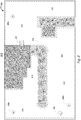
- FIG. 2 illustrates a schematic diagram of a lawn 200 for a robotic garden tool 202 , according to an embodiment of the present invention.
- the robotic garden tool 202 is configured to perform irregular operation within a limited working area 204 .
- the limited area may be any terrain with vegetation, such as lawns, gardens, yards, golf courses, fields, and the like.
- the lawn 200 may include one or more boundaries which may define the working area 204 .
- the signal source 104 is provided to delimit the boundary of the working area 204 .
- the signal source 104 is a boundary wire 206 spread along the perimeter of the working area 204 .
- the boundary wire 206 may be buried inside the ground.
- the signal source 104 produces one or more signals 102 for the robotic garden tool 202 .
- the one or more signals 102 may have particular characteristics associated with it, such as, but not limited to frequency, phase and strength.
- the boundaries of the working area 204 may also be defined by fixed objects 208a, 208b, and 208c as shown in FIG. 2 , fences (not shown) and the like. Further, the sensor unit 106 is mounted in the robotic garden tool 202 , as explained in conjunction with FIG.1 , for detecting one or more signals 102 from the signal source 104 and thus identifying the boundaries of the working area 204 .
- the working area 204 is divided into several subareas 210 , 212 , 214 , 216 , and 218 as shown in FIG. 2 .
- the positioning device 110 is provided on the robotic garden tool 202 . The positioning device 110 is used to define the coordinates of the subareas.
- the control unit 108 provided in the robotic garden tool 202 is adapted to generate a basic map of the working area 204 based on the position co-ordinates of the subareas received from the positioning device 110 and the one or more converted electric signals received from the sensor unit 106 .
- the map may be created automatically. To create the map automatically, the position co-ordinates of the various subareas may be received from the positioning device 110 while the robotic garden tool 202 moves around the working area 204 in an irregular pattern, delimited by the boundary wire 206 . In another embodiment of the present invention, the map may be created manually by an operator. To create the map manually, the robotic garden tool 202 may be placed in different subareas 210-218 on the working area 204 and then receiving the co-ordinates of the subareas 210-218 from the positioning device 110 . The generated map is stored in the memory means 112 of the control unit 108 .
- the generated map may be modified automatically while the robotic garden tool 202 moves within the working area 204 delimited by the boundary wire 206 .
- the map may consist of a grid structure and the robotic garden tool 202 counts the number of times it traverses through each square in the grid in order to maintain a grid counter. For updating the map and reducing the disturbances, each grid counter may be decremented with a fixed interval. Thus, by evaluating the grid counters, the control unit 108 navigates the robotic garden tool 202 in the working area 204 .
- control unit 108 also receives coordinates of an approximate position of the robotic garden tool 202 . Further, the processor means 114 provided in the control unit 108 compares the position co-ordinates of the subareas 210-218 from the map and the co-ordinates of the approximate position of the robotic garden tool 202 to determine a location of the robotic garden tool 202 . Moreover, the processor means 114 also generates one or more commands based on the location of the robotic garden tool 202 or in which subarea the robotic garden tool 202 is at present.
- the one or more commands are based at least in part on one or more operating parameters that may be pre-defined for each of the subareas 210-218 .
- An operating parameter may define a specific height of the grass to be cut in a certain subarea.
- an operating parameter may be the priority or the order in which the subareas should be cut or may define a specific order in which the robotic garden tool 202 should cut the subareas 210-218 .
- an operating parameter may define the time interval between successive mowing over a particular subarea.
- an operating parameter may be time and days on which each subarea should be mowed.
- an operating parameter may define criteria in which mowing over a certain subarea is restricted entirely or for a specific period of time.
- an operating parameter may define the speed at which the robotic garden tool 202 may cut certain subareas 210-218 . This may be helpful to reduce the speed of cutting where more obstacles are present or reducing the speed in narrower areas. Further, in an embodiment of the present invention, the various operating parameters may ensure that all subareas 210-218 are mowed as desired.
- the generated map, the operating parameters and the approximate position of the robotic garden tool 202 enables the control unit 108 to navigate the robotic garden tool 202 to the charging station 220 , when the battery level of the robotic garden tool falls below a predefined threshold.
- the control unit 108 is adapted to navigate the robotic garden tool 202 through the shortest path to the charging station 220 .
- An operating parameter may define a security feature in which the control unit 108 disables the operations of the robotic garden tool 202 , if the robotic garden tool 202 is placed at a location which is not identified in the generated map.
- the above parameters may be programmed into the control unit 108 , and the control unit 108 further saves the parameters into the memory means 112 .
- FIG. 3 illustrates a flow chart of a method 300 for navigating a robotic garden tool in the working area, according to an embodiment of the present invention.
- the working area 204 is divided into several subareas 210 , 212 , 214 , 216 , and 218 .
- the working area 204 of the lawn 200 is defined by boundaries.
- the boundary defines the working area by means of physical fences, fixed objects, surface determination, a boundary wire or the like.
- the boundaries may be identified based on one or more signals 102 generated from a signal source 104 .
- the signal source 104 is a wire, in particular the boundary wire 206 spread along the perimeter of the working area 204 in the lawn 200 .
- the robotic garden tool 202 includes a sensor unit 106 , which is adapted to detect the one or more signals 102 from the signal source 104, as well as other physical objects like fences or fixed objects present in the lawn 200 .
- the robotic garden tool 202 is provided with the positioning device 110 .
- the positioning device 110 may be a standard Global Positioning System (GPS) with low accuracy, or a Local Positioning System. In various embodiments of the present invention, the positioning device 110 may be any device which is capable of providing location based information to the robotic garden tool 202 .
- GPS Global Positioning System
- the positioning device 110 may be any device which is capable of providing location based information to the robotic garden tool 202 .
- the positioning device 110 is adapted to provide position co-ordinates of the working area 204 based on which the working area 204 is defined into various subareas 210-218 .
- the robotic garden tool 202 stores the position co-ordinates of the working area 204 in the memory means 112 of the control unit 108 provided in the robotic garden tool 202 . Further, the robotic garden tool 202 also stores the converted electric signals received from the sensor unit 106 .
- the robotic garden tool 202 is adapted to generate a map of the lawn 202 based on the converted electric signals from the sensor unit 106 and the position co-ordinates of the working area 204 from the positioning device 110 .
- step 308 the processor means 114 provided on the robotic garden tool 202 receives co-ordinates for an approximate position of the robotic garden tool 202 from the positioning device 110 .
- step 310 the processor means 114 compares the position co-ordinates of the subareas 210-218 , based on which the map is generated, and the received approximate position of the robotic garden tool 202 to determine a location of the robotic garden tool 202 or especially in which subarea the robotic garden tool 202 is at present.
- the processor means 114 generates one or more commands based at least in part on the location of the robotic garden tool 202 in the lawn 200 .
- the one or more commands are based on one or more operating parameters defined for each of the subareas 210-218 in the lawn 200 .
- the operating parameters are stored in the memory means 112.
- the operating parameters may include, but not limited to different cutting heights, certain order in which the subareas should be cut, a specific time in which a subarea should be cut, intervals at which a certain subarea should be cut, restricting the entry of the robotic garden tool 202 in certain subareas 210-218 at certain times and the like.
- the control unit 108 is adapted to use the generated map and the current location of the robotic garden tool 202 to find a remote area where the robotic garden tool 202 should be moved.
- the remote area may be the charging station 220 for the robotic garden tool 202 , when the battery of the robotic garden tool 202 falls below a pre-determined threshold.
Landscapes
- Engineering & Computer Science (AREA)
- Physics & Mathematics (AREA)
- Radar, Positioning & Navigation (AREA)
- Remote Sensing (AREA)
- Life Sciences & Earth Sciences (AREA)
- Environmental Sciences (AREA)
- Aviation & Aerospace Engineering (AREA)
- General Physics & Mathematics (AREA)
- Automation & Control Theory (AREA)
- Electromagnetism (AREA)
- Control Of Position, Course, Altitude, Or Attitude Of Moving Bodies (AREA)
- Guiding Agricultural Machines (AREA)
Description
- The present invention relates to a robotic garden tool.
- The robotic garden tools, such as, but not limited to robotic lawnmowers are widely used for grass cutting applications in a lawn. As these robotic garden tools are autonomous, they have to navigate and keep a track of the areas they have performed operations upon. This is particularly important for the case in which the area to be mowed is very large. If the robotic garden tool does not keep the track of the locations it has performed operations upon and which are the remaining locations, then it may take long time to complete the operation in the whole area.
- Normally wires are used to generate reference signals for the robotic garden tool to navigate the robotic garden tool in the lawn. But, the problem with such a system is that the signals generated may not provide any location based information as to where the robotic garden tool currently is. Also, these signals do not provide information as to whether a particular area is mowed and thus it might be possible that the robotic garden tool may mow a particular area multiple times, leading to inefficiency of the complete system.
- The technique currently used to avoid the above mentioned problem is the use of navigation systems, such as, Global Positioning System (GPS). The GPS system may provide accurate data as to where the robotic garden tool is, the areas it has performed operations upon, areas remaining, etc. But the problem associated with such system is that it needs expensive GPS trans-receiver to be mounted on the robotic garden tool. Also, the interconnection between the GPS module and the other parts of the robotic garden tool adds to the complexity and the cost of the whole system. Further, if the contact to the GPS system is lost the robotic garden tool may not know its working area limits and might go off boundary.
- Each of
EP1933467A2 andEP1886549A1 discloses, respectively, a robotic lawnmower configured to operate within an area defined by a boundary wire. The robotic lawnmower has a GPS device for enhanced navigation. - In light of the foregoing, there is a need for an improved method for navigating the robotic garden tool in the lawn area, which will overcome the disadvantages of complex integration, increased cost, flexibility in cutting, along with optimally providing location based data.
- In view of the above, it is an objective of the present invention to solve or at least reduce the problems discussed above. In particular, the objective is to provide a method and a system for navigating a robotic garden tool without complex integration.
- The objective is achieved according to the robotic garden tool described in claim 1.
- According to claim 2, the control unit may be adapted to generate a map based on the coordinates from the low-accuracy positioning device and the one or more signals received from the signal source.
- According to claim 3, the control unit may further be adapted to generate one or more commands based at least in part on the location of the robotic garden tool.
- According to claim 4, the low-accuracy positioning device may be a standard GPS device.
- According to claim 5, the accuracy of the low-accuracy positioning device is less than ±0.1m.
- The invention will in the following be described in more detail with reference to the enclosed drawings, wherein:
-
FIG. 1 illustrates a system for navigating a robotic garden tool, according to an embodiment of the present invention; -
FIG. 2 illustrates an exemplary lawn, according to an embodiment of the present invention; and -
FIG. 3 is a flowchart for illustrating a method for navigating the robotic garden tool, according to an embodiment of the present invention. - The present invention will be described more fully hereinafter with reference to the accompanying drawings, in which example embodiments of the invention incorporating one or more aspects of the present invention are shown. This invention may, however, be embodied in many different forms and should not be construed as limited to the embodiments set forth herein; rather, these embodiments are provided so that this disclosure will be thorough and complete, and will fully convey the scope of the invention to those skilled in the art. For example, one or more aspects of the present invention can be utilized in other embodiments and even other types of devices. In the drawings, like numbers refer to like elements.
-
FIG. 1 illustrates a block diagram of asystem 100, according to an embodiment of the present invention. In an embodiment of the present invention, thesystem 100 may be embodied in a robotic garden tool for navigating the robotic garden tool around the lawn to be mowed. In an embodiment of the present invention, the robotic garden tool may be adapted to operate in a working area of the lawn in an irregular pattern. In various embodiments of the present invention, the robotic garden tool may be a robotic lawn mower. However, it is apparent to a person who is ordinarily skilled in the art that thesystem 100 may also be embodied in any another equipment, such as, but not limited to an automated vacuum cleaner or any other autonomous robotic tool without departing from the scope of the present invention. - In various embodiments of the present invention, the working area of the lawn may be divided into various subareas. Further, in an embodiment of the present invention, the working area of the lawn may be defined by boundaries. In an embodiment of the present invention the boundary may define the working area by means of physical fences, fixed objects, surface determination, a boundary wire and the like. In various embodiments of the present invention, the boundaries may be identified based on one or
more signals 102 generated from asignal source 104. In an embodiment of the present invention, thesignal source 104 may be a wire, in particular a boundary wire spread along the perimeter of the working area in the lawn. - As shown in
FIG. 1 , the robotic garden tool includes asensor unit 106, which is adapted to detect the one ormore signals 102 from thesignal source 104, as well as other physical objects like fences or fixed objects present in the lawn. In an embodiment of the present invention, the one ormore signals 102 include magnetic field signals or electrical current signals from the boundary wire. Thesensor unit 106 further includes one or more sensors, such as, but not limited to, a magnetic field sensor, a current sensor, proximity sensor or photoelectric sensor. Thesensor unit 106 is positioned at a front portion of the robotic garden tool. In another embodiment of the present invention, the sensors may be positioned at any suitable location on the robotic garden tool. - The
sensor unit 106 converts the one ormore signals 102 into equivalent electrical signals. Further, thesensor unit 106 provides the converted equivalent electric signals to acontrol unit 108, provided in the robotic garden tool, for further processing. - Further as shown in
FIG. 1 , thesystem 100 includes a low-accuracy positioning device 110 (herein after referred to as positioning device 110) in the robotic garden tool. In an embodiment of the present invention, thepositioning device 110 may be a standard low-accuracy Global Positioning System (GPS). In an embodiment of the present invention, thepositioning device 110 may be a Local Positioning System. In various embodiments of the present invention, thepositioning device 110 may be any device which is capable of providing location based information to the robotic garden tool. In an embodiment of the present invention, the accuracy of thepositioning device 110 may be ±10m. In another embodiment of the present invention, the accuracy of thepositioning device 110 may be ±3m. In another embodiment of the present invention, the accuracy of thepositioning device 110 may be ±1m. In yet another embodiment of the present invention, the accuracy of thepositioning device 110 may be ±0.1m. - The
positioning device 110 is adapted to provide position co-ordinates of the working area, which is divided into various subareas, to thecontrol unit 108. The position co-ordinates define the various subareas within the working area. Further, thepositioning device 110 is also adapted to provide coordinates for an approximate position of the robotic garden tool to thecontrol unit 108. - As shown in
FIG. 1 , thecontrol unit 108 further includes a memory means 112 and a processing means 114. Thecontrol unit 108 stores the position co-ordinates of the subareas, provided by thepositioning device 110, and the converted equivalent electric signals, provided by thesensor unit 106, in the memory means 112 and/or provide them directly to theprocessing unit 114. - The memory means 112 may be a Random Access Memory (RAM), Read Only Memory (ROM), flash memory or any suitable storage equipment. The memory means 112 may include various modules for storing operating instructions and other software of the
control unit 108. The operating instructions may be a set of computer executable instructions for controlling the overall operations of thecontrol unit 108. The memory means 112 also stores a database of parameters required to send a command to the robotic garden tool based on one or more signals received from thesensor unit 106 and thepositioning device 110. The parameters may also include geometry of the lawn or field, strength of the detected signals, types of detected signals etc. The one or more parameters from the memory means 112 are communicated to the processing means 114 for further processing. - The processing means 114 performs all the computations required to navigate robotic garden tool in different areas of the lawn. The processing means 114 includes an input/output (I/O) interface (not shown), which is operable for receiving the parameters and the computer executable instructions from the memory means 112. The processing means 114 also obtains the converted electrical signals from the
sensor unit 106 through the I/O interface. In another embodiment of the present invention, the processing means 114 also obtains position co-ordinates from thepositioning device 110 through the I/O interface. - The processing means 114 generates a map of the lawn based on the electric signals from the
sensor unit 106 and the position co-ordinates of the various subareas within the working area, from thepositioning device 110. - The processor means 114 also receives co-ordinates for an approximate position of the robotic garden tool from the
positioning device 110. Further, the processor means 114 compares the position co-ordinates of the subareas, based on which the map is generated, and the received approximate position of the robotic garden tool to determine a location of the robotic garden tool or especially in which subarea the robotic garden tool is at present. The processor means 114 generates one or more commands based at least in part on the location of the garden tool in the lawn. - The one or more commands are based on various operating parameters defined for each of the subareas in the lawn. The operating parameters are stored in the memory means 112. The operating parameters may include, but not limited to different cutting heights, certain order in which the subareas should be cut, a specific time in which a subarea should be cut, intervals at which a certain subarea should be cut, restricting the entry of the robotic garden tool in certain subareas at certain times and the like.
- The
control unit 108 is adapted to use the generated map and the current location of the robotic garden tool to find a remote area where the robotic garden tool should be moved. In an embodiment of the present invention, the remote area may be a charging station for the robotic garden tool, when the battery of the robotic garden tool falls below a pre-determined threshold. -
FIG. 2 illustrates a schematic diagram of alawn 200 for arobotic garden tool 202, according to an embodiment of the present invention. Therobotic garden tool 202 is configured to perform irregular operation within alimited working area 204. The limited area may be any terrain with vegetation, such as lawns, gardens, yards, golf courses, fields, and the like. - The
lawn 200 may include one or more boundaries which may define the workingarea 204. Thesignal source 104 is provided to delimit the boundary of the workingarea 204. In an embodiment of the present invention, thesignal source 104 is aboundary wire 206 spread along the perimeter of the workingarea 204. Theboundary wire 206 may be buried inside the ground. Further, thesignal source 104 produces one ormore signals 102 for therobotic garden tool 202. The one ormore signals 102 may have particular characteristics associated with it, such as, but not limited to frequency, phase and strength. - The boundaries of the working
area 204 may also be defined byfixed objects FIG. 2 , fences (not shown) and the like. Further, thesensor unit 106 is mounted in therobotic garden tool 202, as explained in conjunction withFIG.1 , for detecting one ormore signals 102 from thesignal source 104 and thus identifying the boundaries of the workingarea 204. - To overcome the disadvantages of irregular geography of the working
area 204, the workingarea 204 is divided intoseveral subareas FIG. 2 . To add the subareas based information in therobotic garden tool 202, thepositioning device 110 is provided on therobotic garden tool 202. Thepositioning device 110 is used to define the coordinates of the subareas. - The
control unit 108 provided in therobotic garden tool 202 is adapted to generate a basic map of the workingarea 204 based on the position co-ordinates of the subareas received from thepositioning device 110 and the one or more converted electric signals received from thesensor unit 106. - The map may be created automatically. To create the map automatically, the position co-ordinates of the various subareas may be received from the
positioning device 110 while therobotic garden tool 202 moves around the workingarea 204 in an irregular pattern, delimited by theboundary wire 206. In another embodiment of the present invention, the map may be created manually by an operator. To create the map manually, therobotic garden tool 202 may be placed in different subareas 210-218 on the workingarea 204 and then receiving the co-ordinates of the subareas 210-218 from thepositioning device 110. The generated map is stored in the memory means 112 of thecontrol unit 108. - The generated map may be modified automatically while the
robotic garden tool 202 moves within the workingarea 204 delimited by theboundary wire 206. The map may consist of a grid structure and therobotic garden tool 202 counts the number of times it traverses through each square in the grid in order to maintain a grid counter. For updating the map and reducing the disturbances, each grid counter may be decremented with a fixed interval. Thus, by evaluating the grid counters, thecontrol unit 108 navigates therobotic garden tool 202 in the workingarea 204. - At any given instant, the
control unit 108 also receives coordinates of an approximate position of therobotic garden tool 202. Further, the processor means 114 provided in thecontrol unit 108 compares the position co-ordinates of the subareas 210-218 from the map and the co-ordinates of the approximate position of therobotic garden tool 202 to determine a location of therobotic garden tool 202. Moreover, the processor means 114 also generates one or more commands based on the location of therobotic garden tool 202 or in which subarea therobotic garden tool 202 is at present. - The one or more commands are based at least in part on one or more operating parameters that may be pre-defined for each of the subareas 210-218. An operating parameter may define a specific height of the grass to be cut in a certain subarea. In another embodiment of the present invention, an operating parameter may be the priority or the order in which the subareas should be cut or may define a specific order in which the
robotic garden tool 202 should cut the subareas 210-218. In another embodiment of the present invention, an operating parameter may define the time interval between successive mowing over a particular subarea. In an embodiment of the present invention, an operating parameter may be time and days on which each subarea should be mowed. In another embodiment of the present invention, an operating parameter may define criteria in which mowing over a certain subarea is restricted entirely or for a specific period of time. In still another embodiment of the present invention, an operating parameter may define the speed at which therobotic garden tool 202 may cut certain subareas 210-218. This may be helpful to reduce the speed of cutting where more obstacles are present or reducing the speed in narrower areas. Further, in an embodiment of the present invention, the various operating parameters may ensure that all subareas 210-218 are mowed as desired. - The generated map, the operating parameters and the approximate position of the
robotic garden tool 202 enables thecontrol unit 108 to navigate therobotic garden tool 202 to the chargingstation 220, when the battery level of the robotic garden tool falls below a predefined threshold. Thecontrol unit 108 is adapted to navigate therobotic garden tool 202 through the shortest path to the chargingstation 220. - An operating parameter may define a security feature in which the
control unit 108 disables the operations of therobotic garden tool 202, if therobotic garden tool 202 is placed at a location which is not identified in the generated map. - The above parameters may be programmed into the
control unit 108, and thecontrol unit 108 further saves the parameters into the memory means 112. -
FIG. 3 illustrates a flow chart of amethod 300 for navigating a robotic garden tool in the working area, according to an embodiment of the present invention. Instep 302, the workingarea 204 is divided intoseveral subareas area 204 of thelawn 200 is defined by boundaries. The boundary defines the working area by means of physical fences, fixed objects, surface determination, a boundary wire or the like. The boundaries may be identified based on one ormore signals 102 generated from asignal source 104. Thesignal source 104 is a wire, in particular theboundary wire 206 spread along the perimeter of the workingarea 204 in thelawn 200. - The
robotic garden tool 202 includes asensor unit 106, which is adapted to detect the one ormore signals 102 from thesignal source 104, as well as other physical objects like fences or fixed objects present in thelawn 200. - Further, in
step 304, therobotic garden tool 202 is provided with thepositioning device 110. Thepositioning device 110 may be a standard Global Positioning System (GPS) with low accuracy, or a Local Positioning System. In various embodiments of the present invention, thepositioning device 110 may be any device which is capable of providing location based information to therobotic garden tool 202. - The
positioning device 110 is adapted to provide position co-ordinates of the workingarea 204 based on which the workingarea 204 is defined into various subareas 210-218. - In
step 306, therobotic garden tool 202 stores the position co-ordinates of the workingarea 204 in the memory means 112 of thecontrol unit 108 provided in therobotic garden tool 202. Further, therobotic garden tool 202 also stores the converted electric signals received from thesensor unit 106. - The
robotic garden tool 202 is adapted to generate a map of thelawn 202 based on the converted electric signals from thesensor unit 106 and the position co-ordinates of the workingarea 204 from thepositioning device 110. - In
step 308, the processor means 114 provided on therobotic garden tool 202 receives co-ordinates for an approximate position of therobotic garden tool 202 from thepositioning device 110. - Further, in
step 310, the processor means 114 compares the position co-ordinates of the subareas 210-218, based on which the map is generated, and the received approximate position of therobotic garden tool 202 to determine a location of therobotic garden tool 202 or especially in which subarea therobotic garden tool 202 is at present. - The processor means 114 generates one or more commands based at least in part on the location of the
robotic garden tool 202 in thelawn 200. The one or more commands are based on one or more operating parameters defined for each of the subareas 210-218 in thelawn 200. The operating parameters are stored in the memory means 112. The operating parameters may include, but not limited to different cutting heights, certain order in which the subareas should be cut, a specific time in which a subarea should be cut, intervals at which a certain subarea should be cut, restricting the entry of therobotic garden tool 202 in certain subareas 210-218 at certain times and the like. - The
control unit 108 is adapted to use the generated map and the current location of therobotic garden tool 202 to find a remote area where therobotic garden tool 202 should be moved. The remote area may be the chargingstation 220 for therobotic garden tool 202, when the battery of therobotic garden tool 202 falls below a pre-determined threshold.
Claims (5)
- A robotic garden tool (202) configured to operate in a lawn (200) within a predetermined working area (204) defined by boundaries, the perimeter of the working area (204) being defined by a boundary wire (206) sending electrical signals, which working area (204) is divided into subareas (210-218), wherein the robotic garden tool (202) is adapted to operate in the working area (204) in an irregular pattern, the robotic garden tool (202) comprising:at least one sensor unit (106) configured to detect the boundaries based on one or more signals (102) provided by a signal source (104);a low-accuracy positioning device (110) for defining the subareas (210-218) based on coordinates from the low-accuracy positioning device (110), wherein the low-accuracy local positioning device (110) is adapted to provide an approximate position of the robotic garden tool (202) in a subarea; anda control unit (108) comprising at least one processor means (114) and a memory means (112), wherein the robotic garden tool is characterized in thatthe processor means (114) is adapted to compare the coordinates for the subareas (210-218) with the coordinates for an approximate position of the robotic garden tool (202) from the low-accuracy positioning device (110), to determine in which subarea the robotic garden tool (202) is at present.
- A robotic garden tool (202) according to claim 1, wherein the control unit (108) is adapted to generate a map based on the coordinates from the low-accuracy positioning device (110) and the one or more signals (102) received from the signal source (104).
- A robotic garden tool (202) according to claim 1, wherein the control unit (108) is adapted to generate one or more commands based at least in part on the location of the robotic garden tool (202).
- A robotic garden tool (202) according to any of the claims 1-3, wherein the low-accuracy positioning device (110) is a standard GPS device.
- A robotic garden tool (202) according to any of the claims 1-4, wherein the accuracy of the low-accuracy positioning device (110) is less than ±0.1m.
Applications Claiming Priority (3)
| Application Number | Priority Date | Filing Date | Title |
|---|---|---|---|
| PCT/SE2010/050293 WO2011115534A1 (en) | 2010-03-17 | 2010-03-17 | Method and system for navigating a robotic garden tool |
| PCT/SE2011/050291 WO2011115563A1 (en) | 2010-03-17 | 2011-03-17 | Method and system for navigating a robotic garden tool |
| EP11756635.6A EP2547192B1 (en) | 2010-03-17 | 2011-03-17 | Method and system for navigating a robotic garden tool |
Related Parent Applications (1)
| Application Number | Title | Priority Date | Filing Date |
|---|---|---|---|
| EP11756635.6A Division EP2547192B1 (en) | 2010-03-17 | 2011-03-17 | Method and system for navigating a robotic garden tool |
Publications (2)
| Publication Number | Publication Date |
|---|---|
| EP3366100A1 EP3366100A1 (en) | 2018-08-29 |
| EP3366100B1 true EP3366100B1 (en) | 2020-04-08 |
Family
ID=44649446
Family Applications (2)
| Application Number | Title | Priority Date | Filing Date |
|---|---|---|---|
| EP11756635.6A Active EP2547192B1 (en) | 2010-03-17 | 2011-03-17 | Method and system for navigating a robotic garden tool |
| EP18152871.2A Active EP3366100B1 (en) | 2010-03-17 | 2011-03-17 | Robotic garden tool |
Family Applications Before (1)
| Application Number | Title | Priority Date | Filing Date |
|---|---|---|---|
| EP11756635.6A Active EP2547192B1 (en) | 2010-03-17 | 2011-03-17 | Method and system for navigating a robotic garden tool |
Country Status (4)
| Country | Link |
|---|---|
| US (1) | US8938318B2 (en) |
| EP (2) | EP2547192B1 (en) |
| NO (1) | NO2547192T3 (en) |
| WO (2) | WO2011115534A1 (en) |
Families Citing this family (58)
| Publication number | Priority date | Publication date | Assignee | Title |
|---|---|---|---|---|
| ES2681523T3 (en) | 2006-03-17 | 2018-09-13 | Irobot Corporation | Lawn Care Robot |
| US9026299B2 (en) | 2012-07-09 | 2015-05-05 | Deere & Company | Navigation system and method for autonomous mower |
| US9072218B2 (en) | 2012-07-09 | 2015-07-07 | Deere & Company | Boundary sensor assembly for a robotic lawn mower, robotic lawn mower and robotic lawn mower system |
| WO2014058358A1 (en) | 2012-10-09 | 2014-04-17 | Husqvarna Ab | Method and system for enhancing a coverage distribution of a robotic garden tool |
| WO2014101840A1 (en) | 2012-12-28 | 2014-07-03 | 苏州宝时得电动工具有限公司 | Auto mowing system |
| US10149430B2 (en) * | 2013-02-20 | 2018-12-11 | Husqvarna Ab | Robotic work tool configured for improved turning in a slope, a robotic work tool system, and a method for use in the robot work tool |
| WO2014145996A1 (en) | 2013-03-15 | 2014-09-18 | Mtd Products Inc | Autonomous mobile work system comprising a variable reflectivity base station |
| EP3018987B1 (en) * | 2013-07-10 | 2020-09-02 | Agco Corporation | Automating distribution of work in a field |
| DE102013107492A1 (en) * | 2013-07-15 | 2015-01-15 | Koubachi AG | System for monitoring and controlling activities of at least one gardening tool within at least one activity area |
| WO2015072897A1 (en) * | 2013-11-12 | 2015-05-21 | Husqvarna Ab | Improved navigation for a robotic working tool |
| EP3126921B1 (en) | 2014-03-31 | 2021-02-24 | iRobot Corporation | Autonomous mobile robot |
| US9516806B2 (en) | 2014-10-10 | 2016-12-13 | Irobot Corporation | Robotic lawn mowing boundary determination |
| US9510505B2 (en) | 2014-10-10 | 2016-12-06 | Irobot Corporation | Autonomous robot localization |
| US9788481B2 (en) * | 2014-10-28 | 2017-10-17 | Deere & Company | Robotic mower navigation system |
| GB201419883D0 (en) | 2014-11-07 | 2014-12-24 | F Robotics Acquisitions Ltd | Domestic robotic system and method |
| US9804594B2 (en) * | 2014-11-07 | 2017-10-31 | Clearpath Robotics, Inc. | Self-calibrating sensors and actuators for unmanned vehicles |
| US10444756B2 (en) | 2014-12-11 | 2019-10-15 | Husqvarna Ab | Navigation for a robotic working tool |
| US9420741B2 (en) | 2014-12-15 | 2016-08-23 | Irobot Corporation | Robot lawnmower mapping |
| US9701020B1 (en) * | 2014-12-16 | 2017-07-11 | Bobsweep Inc. | Method and system for robotic surface coverage |
| US10488865B2 (en) * | 2014-12-16 | 2019-11-26 | Al Incorporated | Methods and systems for robotic surface coverage |
| US9538702B2 (en) | 2014-12-22 | 2017-01-10 | Irobot Corporation | Robotic mowing of separated lawn areas |
| US10643377B2 (en) * | 2014-12-22 | 2020-05-05 | Husqvarna Ab | Garden mapping and planning via robotic vehicle |
| JP6193898B2 (en) * | 2015-02-10 | 2017-09-06 | 本田技研工業株式会社 | Control device for autonomous vehicle |
| CN105988415B (en) * | 2015-02-13 | 2019-09-20 | 苏州宝时得电动工具有限公司 | Multizone cutting control system and its control method |
| JP5973608B1 (en) * | 2015-03-27 | 2016-08-23 | 本田技研工業株式会社 | Control equipment for unmanned work vehicles |
| JP5973609B1 (en) * | 2015-03-27 | 2016-08-23 | 本田技研工業株式会社 | Control equipment for unmanned work vehicles |
| DE102015104937A1 (en) * | 2015-03-31 | 2016-10-06 | Valeo Schalter Und Sensoren Gmbh | A method for assessing a membership of a detection point to an object in an environmental region of a motor vehicle and driver assistance system |
| US11115798B2 (en) | 2015-07-23 | 2021-09-07 | Irobot Corporation | Pairing a beacon with a mobile robot |
| US10034421B2 (en) | 2015-07-24 | 2018-07-31 | Irobot Corporation | Controlling robotic lawnmowers |
| EP3156873B2 (en) | 2015-10-15 | 2023-04-05 | Honda Research Institute Europe GmbH | Autonomous vehicle with improved simultaneous localization and mapping function |
| DE102015221658A1 (en) * | 2015-11-04 | 2017-05-04 | Robert Bosch Gmbh | Garden sensor device |
| EP3392729B1 (en) | 2015-12-17 | 2021-10-27 | Positec Power Tools (Suzhou) Co., Ltd | Auto-movement robot system |
| US10021830B2 (en) | 2016-02-02 | 2018-07-17 | Irobot Corporation | Blade assembly for a grass cutting mobile robot |
| US10459063B2 (en) | 2016-02-16 | 2019-10-29 | Irobot Corporation | Ranging and angle of arrival antenna system for a mobile robot |
| WO2017192981A1 (en) | 2016-05-06 | 2017-11-09 | Mtd Products Inc | Autonomous mower navigation system and method |
| US11172608B2 (en) | 2016-06-30 | 2021-11-16 | Tti (Macao Commercial Offshore) Limited | Autonomous lawn mower and a system for navigating thereof |
| EP3469442A4 (en) | 2016-06-30 | 2020-09-16 | TTI (Macao Commercial Offshore) Limited | An autonomous lawn mower and a system for navigating thereof |
| WO2018014838A1 (en) * | 2016-07-19 | 2018-01-25 | 苏州宝时得电动工具有限公司 | Self-moving gardening robot and system thereof |
| US10405440B2 (en) | 2017-04-10 | 2019-09-03 | Romello Burdoucci | System and method for interactive protection of a mobile electronic device |
| US9807930B1 (en) | 2016-08-25 | 2017-11-07 | Irobot Corporation | Blade guard for a robot lawnmower |
| WO2019013989A1 (en) | 2017-07-14 | 2019-01-17 | Irobot Corporation | Blade assembly for a grass cutting mobile robot |
| US10767383B2 (en) * | 2017-11-07 | 2020-09-08 | Robin Technologies, Inc. | Ground wire guidance system for robotic vehicle with doorway access |
| CN107788916B (en) * | 2017-11-08 | 2018-09-28 | 安嘉琦 | Smart home cleans all-in-one machine |
| CN107822565B (en) * | 2017-11-08 | 2020-06-26 | 上海雷盎云智能技术有限公司 | Intelligent household sweeper capable of achieving slit cleaning based on data analysis |
| EP3684162B1 (en) | 2017-11-20 | 2021-01-27 | The Toro Company | System and method for operating an autonomous robotic working machine within a travelling containment zone |
| CN107977003B (en) * | 2017-11-28 | 2020-07-31 | 深圳市杉川机器人有限公司 | Area cleaning method and device |
| US11197414B2 (en) | 2018-01-26 | 2021-12-14 | Briggs & Stratton, Llc | Systems and devices for autonomous lawn care |
| EP3833176B1 (en) | 2018-08-08 | 2024-06-12 | The Toro Company | Autonomous machine navigation and training using vision system |
| CN111198557B (en) * | 2018-10-31 | 2022-03-18 | 苏州科瓴精密机械科技有限公司 | Control method and control system for walking robot |
| CN111324111B (en) * | 2018-12-13 | 2022-11-01 | 苏州科瓴精密机械科技有限公司 | Method for recognizing boundary signal and robot system |
| US20220163971A1 (en) * | 2019-01-28 | 2022-05-26 | VEKTOR Dynamics A/S | Robotic vehicle with safety measures |
| IT201900010650A1 (en) | 2019-07-02 | 2021-01-02 | Stiga S P A In Breve Anche St S P A | MOBILE DEVICE, METHOD TO ESTIMATE THE UNCERTAINTY OF THE POSITION OF SUCH MOBILE DEVICE AND METHOD TO ESTIMATE THE ORIENTATION OF SUCH MOBILE DEVICE |
| US11937539B2 (en) | 2019-08-28 | 2024-03-26 | Samsung Electronics Co., Ltd. | Sensor fusion for localization and path planning |
| WO2021106331A1 (en) * | 2019-11-25 | 2021-06-03 | 村田機械株式会社 | Autonomous traveling dolly, control method, and program |
| JP2021112146A (en) * | 2020-01-17 | 2021-08-05 | 本田技研工業株式会社 | Implement and work system |
| JP2022068643A (en) * | 2020-10-22 | 2022-05-10 | 本田技研工業株式会社 | Autonomous work system |
| JP2022108134A (en) * | 2021-01-12 | 2022-07-25 | 本田技研工業株式会社 | Information processor, work management system, and work management method |
| CN113519253B (en) * | 2021-07-02 | 2023-03-17 | 宁波瑞霖机械科技有限公司 | Mower route regression method and system, storage medium and mower |
Family Cites Families (15)
| Publication number | Priority date | Publication date | Assignee | Title |
|---|---|---|---|---|
| US5086535A (en) * | 1990-10-22 | 1992-02-11 | Racine Industries, Inc. | Machine and method using graphic data for treating a surface |
| US5204814A (en) * | 1990-11-13 | 1993-04-20 | Mobot, Inc. | Autonomous lawn mower |
| IL113913A (en) | 1995-05-30 | 2000-02-29 | Friendly Machines Ltd | Navigation method and system |
| US5944132A (en) | 1995-07-20 | 1999-08-31 | Golfpro International, Inc. | Method and apparatus for controlling robotic golf caddy apparatus |
| JP2000029517A (en) | 1998-07-10 | 2000-01-28 | Fuji Heavy Ind Ltd | Traveling controller for autonomous traveling vehicle |
| US6338013B1 (en) * | 1999-03-19 | 2002-01-08 | Bryan John Ruffner | Multifunctional mobile appliance |
| US20030144774A1 (en) | 2002-01-29 | 2003-07-31 | Trissel Ronald L. | Kit and method for converting conventional lawnmower to a robotic lawnmower |
| GB2386971B (en) * | 2002-03-26 | 2005-11-30 | Mcmurtry Ltd | Method of operating an automated land maintenance vehicle |
| ES2681523T3 (en) * | 2006-03-17 | 2018-09-13 | Irobot Corporation | Lawn Care Robot |
| ITFI20060202A1 (en) * | 2006-08-07 | 2008-02-08 | Fabrizio Bernini | APPARATUS FOR CHECKING THE MOVEMENT OF AN AUTOMATIC SELF PROPELLED TERRESTRIAL VEHICLE |
| US20080039991A1 (en) * | 2006-08-10 | 2008-02-14 | May Reed R | Methods and systems for providing accurate vehicle positioning |
| US7499155B2 (en) * | 2006-08-23 | 2009-03-03 | Bryan Cappelletti | Local positioning navigation system |
| US8306659B2 (en) * | 2006-12-06 | 2012-11-06 | F Robotics Acquisitions Ltd. | Autonomous robot |
| US8428776B2 (en) * | 2009-06-18 | 2013-04-23 | Michael Todd Letsky | Method for establishing a desired area of confinement for an autonomous robot and autonomous robot implementing a control system for executing the same |
| US8744626B2 (en) * | 2010-05-27 | 2014-06-03 | Deere & Company | Managing autonomous machines across multiple areas |
-
2010
- 2010-03-17 WO PCT/SE2010/050293 patent/WO2011115534A1/en active Application Filing
-
2011
- 2011-03-17 US US13/634,974 patent/US8938318B2/en active Active
- 2011-03-17 WO PCT/SE2011/050291 patent/WO2011115563A1/en active Application Filing
- 2011-03-17 NO NO11756635A patent/NO2547192T3/no unknown
- 2011-03-17 EP EP11756635.6A patent/EP2547192B1/en active Active
- 2011-03-17 EP EP18152871.2A patent/EP3366100B1/en active Active
Non-Patent Citations (1)
| Title |
|---|
| None * |
Also Published As
| Publication number | Publication date |
|---|---|
| EP2547192B1 (en) | 2018-01-24 |
| WO2011115534A1 (en) | 2011-09-22 |
| US8938318B2 (en) | 2015-01-20 |
| EP3366100A1 (en) | 2018-08-29 |
| EP2547192A1 (en) | 2013-01-23 |
| NO2547192T3 (en) | 2018-06-23 |
| EP2547192A4 (en) | 2015-08-19 |
| WO2011115563A1 (en) | 2011-09-22 |
| US20130006419A1 (en) | 2013-01-03 |
Similar Documents
| Publication | Publication Date | Title |
|---|---|---|
| EP3366100B1 (en) | Robotic garden tool | |
| US8942862B2 (en) | Method and system for guiding a robotic garden tool to a predetermined position | |
| EP3346348B1 (en) | Robotic garden tool following wires at a distance using multiple signals | |
| US8838291B2 (en) | Communication and safety device for boundary aided systems | |
| EP3373097B1 (en) | Robotic mower with object detection system | |
| EP2906032B1 (en) | System for enhancing a coverage distribution of a robotic garden tool | |
| EP3158410B1 (en) | Automatic beacon position determination | |
| EP3695701B1 (en) | Robotic vehicle for boundaries determination | |
| EP4002985B1 (en) | Robotic lawn mower control | |
| EP3761141B1 (en) | Method for mapping a working area of a mobile device | |
| RU131276U1 (en) | DEVICE FOR COORDINATION OF AUTOMATED DEVICES | |
| WO2014074026A1 (en) | A method for navigation and joint coordination of automated devices | |
| EP4193820B1 (en) | Path planning system and method for defining a harvest path for harvesting a crop material from a field | |
| EP4375710A1 (en) | Determining a location to place a base station device used by a robotic garden tool | |
| US20220000018A1 (en) | Marking of Features for a Robotic Lawnmower | |
| CN117751748A (en) | Operation equipment system and control method thereof | |
| WO2014074025A1 (en) | Apparatus for coordinating automated devices |
Legal Events
| Date | Code | Title | Description |
|---|---|---|---|
| PUAI | Public reference made under article 153(3) epc to a published international application that has entered the european phase |
Free format text: ORIGINAL CODE: 0009012 |
|
| STAA | Information on the status of an ep patent application or granted ep patent |
Free format text: STATUS: THE APPLICATION HAS BEEN PUBLISHED |
|
| AC | Divisional application: reference to earlier application |
Ref document number: 2547192 Country of ref document: EP Kind code of ref document: P |
|
| AK | Designated contracting states |
Kind code of ref document: A1 Designated state(s): AL AT BE BG CH CY CZ DE DK EE ES FI FR GB GR HR HU IE IS IT LI LT LU LV MC MK MT NL NO PL PT RO RS SE SI SK SM TR |
|
| STAA | Information on the status of an ep patent application or granted ep patent |
Free format text: STATUS: REQUEST FOR EXAMINATION WAS MADE |
|
| STAA | Information on the status of an ep patent application or granted ep patent |
Free format text: STATUS: EXAMINATION IS IN PROGRESS |
|
| 17P | Request for examination filed |
Effective date: 20190220 |
|
| RBV | Designated contracting states (corrected) |
Designated state(s): AL AT BE BG CH CY CZ DE DK EE ES FI FR GB GR HR HU IE IS IT LI LT LU LV MC MK MT NL NO PL PT RO RS SE SI SK SM TR |
|
| 17Q | First examination report despatched |
Effective date: 20190320 |
|
| GRAP | Despatch of communication of intention to grant a patent |
Free format text: ORIGINAL CODE: EPIDOSNIGR1 |
|
| STAA | Information on the status of an ep patent application or granted ep patent |
Free format text: STATUS: GRANT OF PATENT IS INTENDED |
|
| INTG | Intention to grant announced |
Effective date: 20191112 |
|
| GRAS | Grant fee paid |
Free format text: ORIGINAL CODE: EPIDOSNIGR3 |
|
| GRAA | (expected) grant |
Free format text: ORIGINAL CODE: 0009210 |
|
| STAA | Information on the status of an ep patent application or granted ep patent |
Free format text: STATUS: THE PATENT HAS BEEN GRANTED |
|
| AC | Divisional application: reference to earlier application |
Ref document number: 2547192 Country of ref document: EP Kind code of ref document: P |
|
| AK | Designated contracting states |
Kind code of ref document: B1 Designated state(s): AL AT BE BG CH CY CZ DE DK EE ES FI FR GB GR HR HU IE IS IT LI LT LU LV MC MK MT NL NO PL PT RO RS SE SI SK SM TR |
|
| REG | Reference to a national code |
Ref country code: CH Ref legal event code: EP Ref country code: AT Ref legal event code: REF Ref document number: 1253100 Country of ref document: AT Kind code of ref document: T Effective date: 20200415 |
|
| REG | Reference to a national code |
Ref country code: DE Ref legal event code: R096 Ref document number: 602011066220 Country of ref document: DE |
|
| REG | Reference to a national code |
Ref country code: IE Ref legal event code: FG4D |
|
| REG | Reference to a national code |
Ref country code: NL Ref legal event code: MP Effective date: 20200408 |
|
| REG | Reference to a national code |
Ref country code: LT Ref legal event code: MG4D |
|
| PG25 | Lapsed in a contracting state [announced via postgrant information from national office to epo] |
Ref country code: IS Free format text: LAPSE BECAUSE OF FAILURE TO SUBMIT A TRANSLATION OF THE DESCRIPTION OR TO PAY THE FEE WITHIN THE PRESCRIBED TIME-LIMIT Effective date: 20200808 Ref country code: NL Free format text: LAPSE BECAUSE OF FAILURE TO SUBMIT A TRANSLATION OF THE DESCRIPTION OR TO PAY THE FEE WITHIN THE PRESCRIBED TIME-LIMIT Effective date: 20200408 Ref country code: PT Free format text: LAPSE BECAUSE OF FAILURE TO SUBMIT A TRANSLATION OF THE DESCRIPTION OR TO PAY THE FEE WITHIN THE PRESCRIBED TIME-LIMIT Effective date: 20200817 Ref country code: LT Free format text: LAPSE BECAUSE OF FAILURE TO SUBMIT A TRANSLATION OF THE DESCRIPTION OR TO PAY THE FEE WITHIN THE PRESCRIBED TIME-LIMIT Effective date: 20200408 Ref country code: GR Free format text: LAPSE BECAUSE OF FAILURE TO SUBMIT A TRANSLATION OF THE DESCRIPTION OR TO PAY THE FEE WITHIN THE PRESCRIBED TIME-LIMIT Effective date: 20200709 Ref country code: NO Free format text: LAPSE BECAUSE OF FAILURE TO SUBMIT A TRANSLATION OF THE DESCRIPTION OR TO PAY THE FEE WITHIN THE PRESCRIBED TIME-LIMIT Effective date: 20200708 Ref country code: SE Free format text: LAPSE BECAUSE OF FAILURE TO SUBMIT A TRANSLATION OF THE DESCRIPTION OR TO PAY THE FEE WITHIN THE PRESCRIBED TIME-LIMIT Effective date: 20200408 Ref country code: FI Free format text: LAPSE BECAUSE OF FAILURE TO SUBMIT A TRANSLATION OF THE DESCRIPTION OR TO PAY THE FEE WITHIN THE PRESCRIBED TIME-LIMIT Effective date: 20200408 |
|
| REG | Reference to a national code |
Ref country code: AT Ref legal event code: MK05 Ref document number: 1253100 Country of ref document: AT Kind code of ref document: T Effective date: 20200408 |
|
| PG25 | Lapsed in a contracting state [announced via postgrant information from national office to epo] |
Ref country code: HR Free format text: LAPSE BECAUSE OF FAILURE TO SUBMIT A TRANSLATION OF THE DESCRIPTION OR TO PAY THE FEE WITHIN THE PRESCRIBED TIME-LIMIT Effective date: 20200408 Ref country code: RS Free format text: LAPSE BECAUSE OF FAILURE TO SUBMIT A TRANSLATION OF THE DESCRIPTION OR TO PAY THE FEE WITHIN THE PRESCRIBED TIME-LIMIT Effective date: 20200408 Ref country code: LV Free format text: LAPSE BECAUSE OF FAILURE TO SUBMIT A TRANSLATION OF THE DESCRIPTION OR TO PAY THE FEE WITHIN THE PRESCRIBED TIME-LIMIT Effective date: 20200408 Ref country code: BG Free format text: LAPSE BECAUSE OF FAILURE TO SUBMIT A TRANSLATION OF THE DESCRIPTION OR TO PAY THE FEE WITHIN THE PRESCRIBED TIME-LIMIT Effective date: 20200708 |
|
| PG25 | Lapsed in a contracting state [announced via postgrant information from national office to epo] |
Ref country code: AL Free format text: LAPSE BECAUSE OF FAILURE TO SUBMIT A TRANSLATION OF THE DESCRIPTION OR TO PAY THE FEE WITHIN THE PRESCRIBED TIME-LIMIT Effective date: 20200408 |
|
| REG | Reference to a national code |
Ref country code: DE Ref legal event code: R097 Ref document number: 602011066220 Country of ref document: DE |
|
| PG25 | Lapsed in a contracting state [announced via postgrant information from national office to epo] |
Ref country code: ES Free format text: LAPSE BECAUSE OF FAILURE TO SUBMIT A TRANSLATION OF THE DESCRIPTION OR TO PAY THE FEE WITHIN THE PRESCRIBED TIME-LIMIT Effective date: 20200408 Ref country code: CZ Free format text: LAPSE BECAUSE OF FAILURE TO SUBMIT A TRANSLATION OF THE DESCRIPTION OR TO PAY THE FEE WITHIN THE PRESCRIBED TIME-LIMIT Effective date: 20200408 Ref country code: RO Free format text: LAPSE BECAUSE OF FAILURE TO SUBMIT A TRANSLATION OF THE DESCRIPTION OR TO PAY THE FEE WITHIN THE PRESCRIBED TIME-LIMIT Effective date: 20200408 Ref country code: AT Free format text: LAPSE BECAUSE OF FAILURE TO SUBMIT A TRANSLATION OF THE DESCRIPTION OR TO PAY THE FEE WITHIN THE PRESCRIBED TIME-LIMIT Effective date: 20200408 Ref country code: DK Free format text: LAPSE BECAUSE OF FAILURE TO SUBMIT A TRANSLATION OF THE DESCRIPTION OR TO PAY THE FEE WITHIN THE PRESCRIBED TIME-LIMIT Effective date: 20200408 Ref country code: IT Free format text: LAPSE BECAUSE OF FAILURE TO SUBMIT A TRANSLATION OF THE DESCRIPTION OR TO PAY THE FEE WITHIN THE PRESCRIBED TIME-LIMIT Effective date: 20200408 Ref country code: SM Free format text: LAPSE BECAUSE OF FAILURE TO SUBMIT A TRANSLATION OF THE DESCRIPTION OR TO PAY THE FEE WITHIN THE PRESCRIBED TIME-LIMIT Effective date: 20200408 Ref country code: EE Free format text: LAPSE BECAUSE OF FAILURE TO SUBMIT A TRANSLATION OF THE DESCRIPTION OR TO PAY THE FEE WITHIN THE PRESCRIBED TIME-LIMIT Effective date: 20200408 |
|
| PLBE | No opposition filed within time limit |
Free format text: ORIGINAL CODE: 0009261 |
|
| STAA | Information on the status of an ep patent application or granted ep patent |
Free format text: STATUS: NO OPPOSITION FILED WITHIN TIME LIMIT |
|
| PG25 | Lapsed in a contracting state [announced via postgrant information from national office to epo] |
Ref country code: PL Free format text: LAPSE BECAUSE OF FAILURE TO SUBMIT A TRANSLATION OF THE DESCRIPTION OR TO PAY THE FEE WITHIN THE PRESCRIBED TIME-LIMIT Effective date: 20200408 Ref country code: SK Free format text: LAPSE BECAUSE OF FAILURE TO SUBMIT A TRANSLATION OF THE DESCRIPTION OR TO PAY THE FEE WITHIN THE PRESCRIBED TIME-LIMIT Effective date: 20200408 |
|
| 26N | No opposition filed |
Effective date: 20210112 |
|
| PG25 | Lapsed in a contracting state [announced via postgrant information from national office to epo] |
Ref country code: SI Free format text: LAPSE BECAUSE OF FAILURE TO SUBMIT A TRANSLATION OF THE DESCRIPTION OR TO PAY THE FEE WITHIN THE PRESCRIBED TIME-LIMIT Effective date: 20200408 |
|
| PG25 | Lapsed in a contracting state [announced via postgrant information from national office to epo] |
Ref country code: MC Free format text: LAPSE BECAUSE OF FAILURE TO SUBMIT A TRANSLATION OF THE DESCRIPTION OR TO PAY THE FEE WITHIN THE PRESCRIBED TIME-LIMIT Effective date: 20200408 |
|
| REG | Reference to a national code |
Ref country code: CH Ref legal event code: PL |
|
| GBPC | Gb: european patent ceased through non-payment of renewal fee |
Effective date: 20210317 |
|
| REG | Reference to a national code |
Ref country code: BE Ref legal event code: MM Effective date: 20210331 |
|
| PG25 | Lapsed in a contracting state [announced via postgrant information from national office to epo] |
Ref country code: CH Free format text: LAPSE BECAUSE OF NON-PAYMENT OF DUE FEES Effective date: 20210331 Ref country code: LU Free format text: LAPSE BECAUSE OF NON-PAYMENT OF DUE FEES Effective date: 20210317 Ref country code: LI Free format text: LAPSE BECAUSE OF NON-PAYMENT OF DUE FEES Effective date: 20210331 Ref country code: GB Free format text: LAPSE BECAUSE OF NON-PAYMENT OF DUE FEES Effective date: 20210317 Ref country code: IE Free format text: LAPSE BECAUSE OF NON-PAYMENT OF DUE FEES Effective date: 20210317 Ref country code: FR Free format text: LAPSE BECAUSE OF NON-PAYMENT OF DUE FEES Effective date: 20210331 |
|
| PG25 | Lapsed in a contracting state [announced via postgrant information from national office to epo] |
Ref country code: BE Free format text: LAPSE BECAUSE OF NON-PAYMENT OF DUE FEES Effective date: 20210331 |
|
| PG25 | Lapsed in a contracting state [announced via postgrant information from national office to epo] |
Ref country code: CY Free format text: LAPSE BECAUSE OF FAILURE TO SUBMIT A TRANSLATION OF THE DESCRIPTION OR TO PAY THE FEE WITHIN THE PRESCRIBED TIME-LIMIT Effective date: 20200408 |
|
| P01 | Opt-out of the competence of the unified patent court (upc) registered |
Effective date: 20230419 |
|
| PG25 | Lapsed in a contracting state [announced via postgrant information from national office to epo] |
Ref country code: HU Free format text: LAPSE BECAUSE OF FAILURE TO SUBMIT A TRANSLATION OF THE DESCRIPTION OR TO PAY THE FEE WITHIN THE PRESCRIBED TIME-LIMIT; INVALID AB INITIO Effective date: 20110317 |
|
| PG25 | Lapsed in a contracting state [announced via postgrant information from national office to epo] |
Ref country code: MK Free format text: LAPSE BECAUSE OF FAILURE TO SUBMIT A TRANSLATION OF THE DESCRIPTION OR TO PAY THE FEE WITHIN THE PRESCRIBED TIME-LIMIT Effective date: 20200408 |
|
| PGFP | Annual fee paid to national office [announced via postgrant information from national office to epo] |
Ref country code: DE Payment date: 20240209 Year of fee payment: 14 |
|
| PG25 | Lapsed in a contracting state [announced via postgrant information from national office to epo] |
Ref country code: TR Free format text: LAPSE BECAUSE OF FAILURE TO SUBMIT A TRANSLATION OF THE DESCRIPTION OR TO PAY THE FEE WITHIN THE PRESCRIBED TIME-LIMIT Effective date: 20200408 |
|
| PG25 | Lapsed in a contracting state [announced via postgrant information from national office to epo] |
Ref country code: MT Free format text: LAPSE BECAUSE OF FAILURE TO SUBMIT A TRANSLATION OF THE DESCRIPTION OR TO PAY THE FEE WITHIN THE PRESCRIBED TIME-LIMIT Effective date: 20200408 |