EP3156873B2 - Autonomous vehicle with improved simultaneous localization and mapping function - Google Patents
Autonomous vehicle with improved simultaneous localization and mapping function Download PDFInfo
- Publication number
- EP3156873B2 EP3156873B2 EP15189928.3A EP15189928A EP3156873B2 EP 3156873 B2 EP3156873 B2 EP 3156873B2 EP 15189928 A EP15189928 A EP 15189928A EP 3156873 B2 EP3156873 B2 EP 3156873B2
- Authority
- EP
- European Patent Office
- Prior art keywords
- autonomous vehicle
- autonomous
- map
- signal
- sensor
- Prior art date
- Legal status (The legal status is an assumption and is not a legal conclusion. Google has not performed a legal analysis and makes no representation as to the accuracy of the status listed.)
- Active
Links
- 230000004807 localization Effects 0.000 title claims description 32
- 238000013507 mapping Methods 0.000 title claims description 17
- 230000005672 electromagnetic field Effects 0.000 claims description 33
- 238000010413 gardening Methods 0.000 claims description 6
- 238000004146 energy storage Methods 0.000 claims description 2
- 230000006870 function Effects 0.000 description 13
- 238000000034 method Methods 0.000 description 11
- 230000008859 change Effects 0.000 description 10
- 238000013459 approach Methods 0.000 description 9
- 230000008901 benefit Effects 0.000 description 7
- 230000007613 environmental effect Effects 0.000 description 5
- 230000033001 locomotion Effects 0.000 description 5
- 230000006872 improvement Effects 0.000 description 4
- 230000008569 process Effects 0.000 description 3
- 230000006978 adaptation Effects 0.000 description 2
- 238000004364 calculation method Methods 0.000 description 2
- 230000002596 correlated effect Effects 0.000 description 2
- 238000012545 processing Methods 0.000 description 2
- 238000012549 training Methods 0.000 description 2
- 244000025254 Cannabis sativa Species 0.000 description 1
- 230000006399 behavior Effects 0.000 description 1
- 230000002457 bidirectional effect Effects 0.000 description 1
- 230000001276 controlling effect Effects 0.000 description 1
- 230000000875 corresponding effect Effects 0.000 description 1
- 230000001419 dependent effect Effects 0.000 description 1
- 238000001514 detection method Methods 0.000 description 1
- 238000005286 illumination Methods 0.000 description 1
- 230000003993 interaction Effects 0.000 description 1
- 238000005259 measurement Methods 0.000 description 1
- 230000004044 response Effects 0.000 description 1
- 230000001932 seasonal effect Effects 0.000 description 1
- 230000006641 stabilisation Effects 0.000 description 1
- 238000011105 stabilization Methods 0.000 description 1
- 230000007704 transition Effects 0.000 description 1
- 230000000007 visual effect Effects 0.000 description 1
Images

Classifications
-
- G—PHYSICS
- G05—CONTROLLING; REGULATING
- G05D—SYSTEMS FOR CONTROLLING OR REGULATING NON-ELECTRIC VARIABLES
- G05D1/00—Control of position, course or altitude of land, water, air, or space vehicles, e.g. automatic pilot
- G05D1/0088—Control of position, course or altitude of land, water, air, or space vehicles, e.g. automatic pilot characterized by the autonomous decision making process, e.g. artificial intelligence, predefined behaviours
-
- G—PHYSICS
- G05—CONTROLLING; REGULATING
- G05D—SYSTEMS FOR CONTROLLING OR REGULATING NON-ELECTRIC VARIABLES
- G05D1/00—Control of position, course or altitude of land, water, air, or space vehicles, e.g. automatic pilot
- G05D1/02—Control of position or course in two dimensions
- G05D1/021—Control of position or course in two dimensions specially adapted to land vehicles
- G05D1/0259—Control of position or course in two dimensions specially adapted to land vehicles using magnetic or electromagnetic means
- G05D1/0265—Control of position or course in two dimensions specially adapted to land vehicles using magnetic or electromagnetic means using buried wires
-
- G—PHYSICS
- G05—CONTROLLING; REGULATING
- G05D—SYSTEMS FOR CONTROLLING OR REGULATING NON-ELECTRIC VARIABLES
- G05D1/00—Control of position, course or altitude of land, water, air, or space vehicles, e.g. automatic pilot
- G05D1/02—Control of position or course in two dimensions
- G05D1/021—Control of position or course in two dimensions specially adapted to land vehicles
- G05D1/0212—Control of position or course in two dimensions specially adapted to land vehicles with means for defining a desired trajectory
- G05D1/0219—Control of position or course in two dimensions specially adapted to land vehicles with means for defining a desired trajectory ensuring the processing of the whole working surface
-
- G—PHYSICS
- G05—CONTROLLING; REGULATING
- G05D—SYSTEMS FOR CONTROLLING OR REGULATING NON-ELECTRIC VARIABLES
- G05D1/00—Control of position, course or altitude of land, water, air, or space vehicles, e.g. automatic pilot
- G05D1/02—Control of position or course in two dimensions
- G05D1/021—Control of position or course in two dimensions specially adapted to land vehicles
- G05D1/0231—Control of position or course in two dimensions specially adapted to land vehicles using optical position detecting means
- G05D1/0246—Control of position or course in two dimensions specially adapted to land vehicles using optical position detecting means using a video camera in combination with image processing means
- G05D1/0251—Control of position or course in two dimensions specially adapted to land vehicles using optical position detecting means using a video camera in combination with image processing means extracting 3D information from a plurality of images taken from different locations, e.g. stereo vision
-
- G—PHYSICS
- G05—CONTROLLING; REGULATING
- G05D—SYSTEMS FOR CONTROLLING OR REGULATING NON-ELECTRIC VARIABLES
- G05D1/00—Control of position, course or altitude of land, water, air, or space vehicles, e.g. automatic pilot
- G05D1/02—Control of position or course in two dimensions
- G05D1/021—Control of position or course in two dimensions specially adapted to land vehicles
- G05D1/0268—Control of position or course in two dimensions specially adapted to land vehicles using internal positioning means
- G05D1/027—Control of position or course in two dimensions specially adapted to land vehicles using internal positioning means comprising intertial navigation means, e.g. azimuth detector
-
- G—PHYSICS
- G05—CONTROLLING; REGULATING
- G05D—SYSTEMS FOR CONTROLLING OR REGULATING NON-ELECTRIC VARIABLES
- G05D1/00—Control of position, course or altitude of land, water, air, or space vehicles, e.g. automatic pilot
- G05D1/02—Control of position or course in two dimensions
- G05D1/021—Control of position or course in two dimensions specially adapted to land vehicles
- G05D1/0268—Control of position or course in two dimensions specially adapted to land vehicles using internal positioning means
- G05D1/0274—Control of position or course in two dimensions specially adapted to land vehicles using internal positioning means using mapping information stored in a memory device
Definitions
- the invention relates to an autonomous vehicle with a computing unit to perform a mapping function and a localization function of the vehicle within the map, in particular an autonomous gardening tool such as an autonomous lawn mower or scarifier and a system with such autonomous vehicle and a boundary wire indicating a border of an area in which autonomous driving of the autonomous vehicle shall be performed.
- an autonomous gardening tool such as an autonomous lawn mower or scarifier
- SLAM Simultaneous Localization And Mapping
- SLAM typically data from odometry
- laser scanners and cameras is used.
- the problem is that the better the SLAM result shall be, the more expensive the sensors that provide good results are.
- laser scanners yield good results, but are much more expensive than other sensors.
- odometry and camera data which would be much cheaper to implement than the laser scanners, can be used for indoor environments without any problem, because they lead to robust SLAM results.
- US 2010/0324731 describes an interaction between a user and a lawn mower via Smartphone.
- the mower uses a map that is generated by means of parameter teaching, but of course this means a great effort necessary for the user. Such an effort could be avoided if a robust SLAM technique would be available even for outdoor applications.
- Document WO2014145996 relates to localization and control of an autonomous mobile work system, and, more particularly, to a low cost localization method and system for controlling position of an autonomous mobile work system relative to reflective base stations.
- an autonomous vehicle that comprises a driving means for self-propelling the autonomous vehicle.
- the vehicle further comprises at least one environment sensing means for sensing an environment of the vehicle.
- Such sensing means provides a signal including information perceived to a computing unit that is configured to perform a mapping function and a localization function.
- the mapping function is performed on the basis of the signal or the signals in case of a plurality of sensors in order to generate or build up a map.
- With a localization function localization information on the autonomous vehicle within the map is generated.
- the autonomous vehicle further comprises a boundary distance sensing means.
- a distance signal is generated that is correlated to a distance between the autonomous vehicle and a boundary indication means.
- boundary indication means can be any indicator that can be recognized by the boundary distance sensing means so that a distance can be derived and indicates an edge or borderline of the area in which the autonomous vehicle shall drive.
- the computing unit is configured to receive the distance signal in addition to the signals supplied from the at least one environment sensing means and performs at least one of the mapping function and the localization function on the basis of the signals from the at least one sensing means, but also taking into consideration the distance signal from the boundary distance sensing means.
- the big advantage is that in particular for outdoor situations it cannot be guaranteed that the signals that are provided from the environment sensing means are sufficiently stable in order to ensure a robust SLAM.
- Providing the computing unit further with a distance signal which is a very stable and robust signal since a boundary indication means which is dedicated to indicate an edge of an area can always be detected with the same quality give a great improvement for the SLAM result.
- Such variations of the lighting conditions or the appearance of the environment because of seasonal changes are a big problem for SLAM algorithms that use, for example, data from a camera signal only.
- the same is true for other environment sensing means, like a bump sensor or an accelerator sensor, because all of these environment sensing means are responsive to changes in the environmental conditions.
- SLAM algorithms can be used for outdoor applications in particular for gardening tools such as scarifiers or autonomous lawn mowers when the distance signal is used as an observation for the SLAM algorithm.
- the system which makes use of the autonomous vehicle, according to the aforementioned features, provides in addition to the autonomous vehicle itself a boundary wire that surrounds the area in which the autonomous vehicle shall be capable of moving around freely.
- the use of the distance signal between the autonomous vehicle and such boundary wire has further the advantage that most such systems already make use of a boundary wire for safety reasons.
- the boundary wire is intended to indicate the edge of a working area of such autonomous vehicle, but up to now no information obtained from the boundary wire has been used for SLAM functions. It was only used to detect that the autonomous vehicle reached the edge of its driving area and then a new direction for the vehicle was set.
- the autonomous vehicle is an autonomous gardening device, such as an autonomous lawn mower.
- an autonomous lawn mower or an autonomous scarifier it is in particular important that the SLAM results are robust.
- the information about the map and the localization information including at least information on a current position of the lawn mower can be used to more efficiently mow an area even if this area is of complex layout.
- the random movement of the mower leads to inefficiently mowing a larger area, because it could not be influenced that some portions of the entire area are mowed a plurality of times whereas others are not mowed at all.
- the SLAM technique is used in an autonomous lawn mower (or in autonomous scarifier or in similar outdoor device) and it can be ensured that the SLAM performs properly even though the environmental conditions may change, a great improvement regarding efficiency can be achieved.
- the autonomous vehicle comprises a boundary distance sensing means at least one electromagnetic field sensor. It is particularly advantageous if there is more than one electromagnetic field sensor, because in that case even if the autonomous vehicle does not move, a direction of the autonomous vehicle may be derived from the distance signals obtained by the two electromagnetic field sensors that are arranged on the vehicle distributedly.
- the use of electromagnetic field sensors has further the advantage that such sensors in many cases are integrated in the autonomous gardening tools anyway and thus, no additional sensors need to be mounted on the autonomous vehicle, but signals that are obtained anyway can be used to improve the SLAM results.
- the electromagnetic field sensors comprise at least one boundary wire sensor and/ or a charging station sensor.
- the signal that is derived from sensing the electromagnetic field of the boundary wire it is thus possible to receive a signal from a charging station sensor.
- the charging station sensor is associated with a well-known place. It is a signal which is only transmitted from a single point in the entire area whereas the boundary wire surrounds the whole area.
- Advantageous sensing means for the autonomous vehicle comprise a bump sensor, a sonar sensor, an accelerometer, a compass sensor, a camera or stereo camera.
- a bump sensor a sonar sensor
- an accelerometer a compass sensor
- a camera or stereo camera a camera or stereo camera.
- any combination of such sensors are possible and particularly it is possible to add further sensors that are available for generating information about the environment of the autonomous vehicle.
- the autonomous vehicle comprises a control unit for generating control signals for the driving means of the vehicle.
- control signals are used in order to control the driving means to drive the vehicle in a direction and with a speed that is set by the control unit.
- the control unit On the basis of the map that is generated and having the knowledge of at least the position of the autonomous vehicle within the map, the control unit generates control signals that result in driving the autonomous vehicle as direct to the charging station as possible.
- Previous approaches had the disadvantage that the autonomous vehicle had to drive along the boundary wire until it reached the charging station. But with knowledge of the map that is a representation of the environment of the vehicle and particular the entire area in which the autonomous vehicle can drive, and additionally having the information about the position of the autonomous vehicle within the map, a direct path to the charging station can be realized.
- the "most direct path” does not necessarily mean that it follows a straight line between the current position of the autonomous vehicle towards the charging station, but drives around such obstacles.
- the computing unit has knowledge about the stay times of the autonomous vehicle for each position that is determined by the localization function.
- an analysis can be performed on the stay times of the autonomous vehicle in different segments of an entire environment area that is represented by the map. For example in case that the autonomous vehicle is an autonomous lawn mower, it can be determined which area still needs to be mowed, because the autonomous lawn mower did not yet stay long enough in such a segment of the entire environment.
- control unit for generating control signals for the driving means generates the control signals in such a way that the autonomous vehicle is led to areas that had insufficient stay times of the autonomous vehicle up to that point in time.
- this again means that areas for which insufficient mowing times have been recognized can be headed most directly by the autonomous lawn mower.
- the mowing result will be improved because equalizing of the mowing times over all the different segments of the entire area can be achieved.
- the localization information includes both, position information and heading orientation information of the autonomous vehicle.
- a heading direction can be determined.
- the first control signal that is provided from the control unit to the driving means may already include an information about a change of the heading orientation of the vehicle.
- the heading position of the autonomous vehicle is derived from signals from the at least two electromagnetic field sensors.
- the system includes besides the boundary wire that had already been explained, also a charging station for charging an energy storage of the autonomous vehicle. Furthermore, the charging station is capable of sending a signal that can be detected by the autonomous vehicle as explained above. This signal may deviate in its structure from the signal that is sensed from the boundary wire. Thus, the autonomous vehicle can distinguish between a signal from the boundary wire and the charging station.
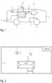
- an autonomous lawn mower 1 is shown in figure 1 .
- the autonomous lawn mower 1 is surrounded by a body work 2 that supports the different units and elements of the autonomous lawn mower 1.
- the body work 2 is connected to a plurality of wheels 3 and 4.
- At least a part of the wheels 3, 4 can be driven by a driving means 5 which in the illustrated embodiment is mechanically connected to wheel 4.
- the driving means 5 including for example an electric motor is connected to two wheels 4 of a rear axle of the autonomous lawn mower 1. By driving the wheels 4 of the rear axle with different rotational speeds, control of the driving direction of the autonomous lawn mower 1 is possible.
- the driving means 5 is controlled by means of signals that are generated by a control unit 6 that is connected to the driving means 5.
- the control unit 6 generates respective driving signals on the basis of which the driving means 5 set the rotational speed of the wheels 4.
- the inventive autonomous lawn mower 1 comprises a computing unit 7.
- the computing unit 7 may be either a single central processing unit or may consist of a plurality of means such as a mapping means 8 and a localization means 9.
- a mapping means 8 may consist of a mapping means 8 and a localization means 9.
- all the functions including the mapping function and the localization function which are to be explained later on are executed by the same unit using a common calculation capability.
- a first environment sensing means can be for example a laser scanner or a camera 10 that is arranged on the top of the vehicle body work 2 in the illustrated embodiment.
- the bump sensor 11 is provided which feeds its signal that is generated in the bump sensor 11 in response to contact with for example obstacles to the computing unit 7.
- the signal of the camera 10 is supplied to the computing unit 7.
- Camera 10 and bump sensor 11 are examples for environment sensing means.
- There may be further environment sensing means provided in the autonomous lawn mower 1 such as, for example, an accelerometer and a compass sensor.
- the camera might be realized as a stereo camera.
- a sonar sensor may be mounted on the autonomous lawn mower 1. All these different sensors feed their signals which are generated from observing the environment of the autonomous lawn mower 1 to the computing unit 7.
- first electromagnetic field sensor 12 and a second electromagnetic field sensor 13 are mounted in a distributed manner on the autonomous lawn mower 1.
- the orientation of the autonomous lawn mower 1 can be calculated from the difference in signal strength of the electromagnetic signal.
- the signals from all of the environment sensing means 10, 11 and furthermore, from the electromagnetic field sensors 12, 13 are fed to the computation means.
- the first electromagnetic field sensor 12 and the second electromagnetic field sensor 13 form a boundary distance sensing means.
- First electromagnetic field sensor 12 and the second electromagnetic field sensor 13 each generate a signal that corresponds to the distance between the autonomous lawn mower 1 and a boundary wire as it will be described later on with respect to figure 2 .
- This distance signal is then used in a SLAM-algorithm together with the signals and data that is derived from the camera 10 and the bump sensor 11.
- the generation of a map from the signals from the environment sensing means 10, 11 and the electromagnetic field sensors 12, 13 is calculated in the mapping means 8.
- Information about the position and maybe orientation of the autonomous lawn mower 1 within this map is calculated by the localization means 9 on the basis of the signals from the environment sensing means 10, 11 and the electromagnetic field sensors 12, 13. It is evident that the environment sensing means 10, 11 may differ from the illustrated embodiment and also that only one of the electromagnetic field sensors 12, 13 is used. Furthermore, it is to be noted that the signals from the electromagnetic field sensors 12, 13 might be used only in either of the mapping means 8 or the localization means 9. But according to the most advantageous embodiment, the signal from the at least two electromagnetic field sensors 12, 13 as boundary distance sensing means are used in both, the mapping means 8 and the localization means 9. By doing so, it is not only possible to generate information about the position of the autonomous lawn mower 1 within the map, but also the orientation of the autonomous lawn mower 1.
- SLAM itself is a well-known technique in robotics. With SLAM simultaneously a map mt and the robots state xt (typically position and orientation of the robot) for every time step t is estimated.
- x t-1 ) just describes the transition probabilities that the robot goes from one state x t-1 into the next state x t .
- the observations include also the signals from the electromagnetic field sensors 12,13.
- an autonomous lawn mower uses the signal strength of a boundary wire signal that surrounds the area of which the map shall be generated.
- a boundary wire is usually present anyway for autonomous lawn mowing systems and it provides an additional observation for localization and mapping. Due to the stability of the wire strength measurement a great improvement with respect to the SLAM algorithm is achieved with nearly no extra costs.
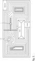
- FIG. 2 An example to explain the inventive approach is given in fig. 2 .
- the situation will be explained on the basis of a top view of a garden with a relatively large area of grass which is interrupted only by a house, a carpark, a flower bed and a tree.
- the dashed line extends along the edge and surrounds the lawn which is to be mowed by the autonomous lawn mower 1.
- the autonomous lawn mower 1 in the situation depicted in fig. 2 is at an arbitrary position on the lawn. Additionally and near the house, there is present a charging station 15 where the autonomous lawn mower 1 needs to be driven to at the end of the mowing process in order to be recharged.
- the boundary wire 15 which surrounds the working area of the autonomous lawn mower 1 emits a weak electromagnetic signal.
- This electromagnetic signal can be sensed by the electronic field sensors 12, 13.
- the computing means 7 now can infer from the signal whether the autonomous lawn mower is inside or outside the area defined by the wire. Furthermore and based on the signal strength of the received electromagnetic signal it can be calculated how close the autonomous lawn mower 1 is to the wire. This information is usually used in order to trigger a turning maneuver when the autonomous lawn mower 1 has reached the boundary wire.
- the wire strength is only a one-dimensional signal that correlates with the distance to the wire. Nevertheless it strongly improves the localization and mapping estimation due to its stability.
- Fig. 3 explains this by showing areas or zones of equal signal strength.
- eight levels S1 to S8 are used for illustrational reasons only.
- the autonomous lawn mower 1 on the basis of the signals generated by the electromagnetic field sensors 12, 13 recognizes that the received signal strength corresponds to the level indicated in the drawing as S8, only a few possible locations remain where the autonomous lawn mower 1 currently can be. Only the striped areas in fig. 3 correspond to the signal strength of S8.
- the eight signal levels S1 to S8 are only used for illustration reasons and of course the suggested linear change in the strength of the wire signal is not necessarily the case.
- the map is built up, the actual distribution of the electromagnetic field strength is automatically learned. Within a known map the information localization can be greatly improved.
- the signal strength that corresponds to a distance signal generated by the electromagnetic field sensors 12, 13 can be used when generating the map but also when localizing the autonomous lawn mower 1 within the generated map.
- the wire signal information in the map might be fixed after some time of learning because a change in the signal is not expected. In contrast the learning and adaptation of the other sensor environment data might continue as these might change.
- the wire signal serves as a stable reference and leads to a stabilization of the map even if a map update is performed for other observed parameters which are perceived by the environment sensing means.
- the illustrated autonomous lawn mower 1 comprises a plurality of electromagnetic field sensors 12, 13, at least two sensors 12, 13.
- the localization information that is generated by the localization means 9 thus includes not only information on the position of the autonomous lawn mower 1 in the map, but also on its orientation.
- the autonomous mower can recognize the charging station when the autonomous lawn mower 1 is within the vicinity of the charging station.
- This additional information which also delivers some information about a particular area in which the autonomous lawn mower 1 currently can only be, is also used to improve mapping and localization, but offers also an extra means for tackling the loop closure problem.
- the loop closure problem per se in SLAM is already known and is the problem of recognizing that a place has already been visited. Closing the loop is necessary so that the driven track of the autonomous lawn mower 1 for which the map has been generated by associating information about the environment with a particular position of the autonomous lawn mower 1. Only by closing the loop, the generated map information gets aligned correctly.
- An autonomous lawn mower in general can use SLAM in two different ways.
- the mapping and localization could be performed in separate steps in such a way that after a training phase that is used to generate the map, the map information is fixed. After such a training phase then only localization of the autonomous lawn mower 1 is performed.
- it is also possible to continuously generate the map which means that using all the information gathered while driving with the autonomous lawn mower 1 in the area limited by the boundary wire is used to improve the currently existing map.
- the learned map can be checked by an operator for errors and misinterpretations with the second approach it is possible to always have an actual map.
- changes in the garden layout for example, new plants
- the distance signal generated from the received boundary wire signal in the SLAM algorithm according to the present invention it is avoided that the map becomes unstable due to many small changes like placing or relocating of chairs or the like.
- the electromagnetic field that is present at a particular place within the map does not change after an initial learning phase and thus can act as a stable reference for later adaptation of the map for other sensor data.
- SLAM technique in outdoor applications or other environments of autonomous vehicles where the environmental conditions change rapidly, a more intelligent behavior of the autonomous vehicle is possible.
- To stick to the example of an autonomous lawn mower 1 it is, for example, possible to more directly head towards the charging station 16 at the end of a mowing session.
- the position of the charging station 16 is known and furthermore, the position of the autonomous lawn mower 1 within the map is known.
- a direct driving path can be calculated by the computing unit 7 and the respective information about a necessary driving direction can be forwarded to the control unit 6.
- the control unit 6 then generates a control signal for driving the driving means 5.
- the calculation of the direction may also include a way driving around an obstacle that is between the autonomous lawn mower 1 and the charging station 16.
- FIG 4 Another aspect is improvement of efficiency in a more complex layout of a lawn as it is shown in figure 4 .
- the entire area consists of three segments A, B and C.
- control algorithms for autonomous lawn mowers relied on the randomly chosen driving directions only.
- a map of the entire area is generated the autonomous lawn mower 1 can be controlled to directly drive from segment B where the charging station 16 is located to segment A or segment C.
- the stay times of the autonomous lawn mower 1 within each segment A, B or C are stored.
- the localization information that is stored within the computation means 7 it can be analyzed if the mowing time in segment A, segment B or segment C corresponds to the size of the respective segment properly.
- a path can be calculated to intentionally drive the lawn mower 1 from segment B to segment A.
- the lawn mower can be brought to segment C.
- Such intentional movement of the autonomous lawn mower 1 can be used for example in addition to the random drive of the lawn mower during the process of mowing.
Description
- The invention relates to an autonomous vehicle with a computing unit to perform a mapping function and a localization function of the vehicle within the map, in particular an autonomous gardening tool such as an autonomous lawn mower or scarifier and a system with such autonomous vehicle and a boundary wire indicating a border of an area in which autonomous driving of the autonomous vehicle shall be performed.
- Over the past few years, it became more and more popular to substitute tools like vacuum cleaners, lawn mowers or scarifier by self-propelled devices that are capable of driving on their own. Thus, no operator is needed that pushes and controls direction of such devices. Of course, the functionality of these devices has been improved over the product cycles up to now. Nevertheless, there are some disadvantages that might be annoying for some users. Maybe the biggest problem is that the driving direction of these devices is determined by chance without knowing anything about the layout of the environment and so the vacuum cleaner or the lawn mower drives around randomly which results inefficiently working on the dedicated area. To improve the devices in that regard, so-called SLAM techniques that are known from the robotic's domain have been introduced also for the autonomous vehicles. SLAM (Simultaneous Localization And Mapping) is the ability to generate a map without human intervention combined with the ability to localize within this map. The self-localization of the autonomous vehicle can be performed even if the process of generating the map is still in progress.
- For SLAM typically data from odometry, laser scanners and cameras is used. The problem is that the better the SLAM result shall be, the more expensive the sensors that provide good results are. For example, laser scanners yield good results, but are much more expensive than other sensors. On the other side, odometry and camera data, which would be much cheaper to implement than the laser scanners, can be used for indoor environments without any problem, because they lead to robust SLAM results.
- But unfortunately, outdoor environments are much more difficult. Thus, in order to provide a vehicle with SLAM-function feasible for outdoor environments also, the SLAM results have to be improved.
- Previous proposals for outdoor applications describe different solutions for autonomous vehicles that do not use the SLAM technique. Since also for other, for example camera-based, approaches (obstacle detection) there is a problem that in outdoor environment the lighting conditions may change significantly,
US 8,958,939 proposes to adjust the speed of the autonomous vehicle to compensate for varying exposure times for the camera. - Further,
US 2010/0324731 describes an interaction between a user and a lawn mower via Smartphone. The mower uses a map that is generated by means of parameter teaching, but of course this means a great effort necessary for the user. Such an effort could be avoided if a robust SLAM technique would be available even for outdoor applications. - Document
WO2014145996 relates to localization and control of an autonomous mobile work system, and, more particularly, to a low cost localization method and system for controlling position of an autonomous mobile work system relative to reflective base stations. - But all these approaches cannot compete with SLAM and the opportunities resulting therefrom. Thus, it is an object of the present invention to provide an autonomous vehicle with an improved SLAM capability
- The problem is solved with the autonomous vehicle and the system including such autonomous vehicle according to the independent claims.
- To achieve the object, an autonomous vehicle is suggested that comprises a driving means for self-propelling the autonomous vehicle. The vehicle further comprises at least one environment sensing means for sensing an environment of the vehicle. Such sensing means provides a signal including information perceived to a computing unit that is configured to perform a mapping function and a localization function. The mapping function is performed on the basis of the signal or the signals in case of a plurality of sensors in order to generate or build up a map. With a localization function, localization information on the autonomous vehicle within the map is generated.
- According to the invention, the autonomous vehicle further comprises a boundary distance sensing means. With this boundary distance sensing means, a distance signal is generated that is correlated to a distance between the autonomous vehicle and a boundary indication means. Such boundary indication means can be any indicator that can be recognized by the boundary distance sensing means so that a distance can be derived and indicates an edge or borderline of the area in which the autonomous vehicle shall drive. The computing unit is configured to receive the distance signal in addition to the signals supplied from the at least one environment sensing means and performs at least one of the mapping function and the localization function on the basis of the signals from the at least one sensing means, but also taking into consideration the distance signal from the boundary distance sensing means.
- The big advantage is that in particular for outdoor situations it cannot be guaranteed that the signals that are provided from the environment sensing means are sufficiently stable in order to ensure a robust SLAM. Providing the computing unit further with a distance signal which is a very stable and robust signal since a boundary indication means which is dedicated to indicate an edge of an area can always be detected with the same quality give a great improvement for the SLAM result. Thus, there is no variation in the signal according to daytime and season. Such variations of the lighting conditions or the appearance of the environment because of seasonal changes are a big problem for SLAM algorithms that use, for example, data from a camera signal only. The same is true for other environment sensing means, like a bump sensor or an accelerator sensor, because all of these environment sensing means are responsive to changes in the environmental conditions.
- Because of the use of the distance signal in addition to the data that is obtained from the environmental sensors the stability and robustness of the SLAM result can be significantly improved. Thus, generally known SLAM algorithms can be used for outdoor applications in particular for gardening tools such as scarifiers or autonomous lawn mowers when the distance signal is used as an observation for the SLAM algorithm.
- The system, which makes use of the autonomous vehicle, according to the aforementioned features, provides in addition to the autonomous vehicle itself a boundary wire that surrounds the area in which the autonomous vehicle shall be capable of moving around freely.
- The use of the distance signal between the autonomous vehicle and such boundary wire has further the advantage that most such systems already make use of a boundary wire for safety reasons. The boundary wire is intended to indicate the edge of a working area of such autonomous vehicle, but up to now no information obtained from the boundary wire has been used for SLAM functions. It was only used to detect that the autonomous vehicle reached the edge of its driving area and then a new direction for the vehicle was set.
- In the dependent claims there are defined a plurality of advantageous embodiments and aspects of the autonomous vehicle.
- In particular, it is an advantage if the autonomous vehicle is an autonomous gardening device, such as an autonomous lawn mower. For such an autonomous lawn mower or an autonomous scarifier it is in particular important that the SLAM results are robust. In such a case, the information about the map and the localization information including at least information on a current position of the lawn mower can be used to more efficiently mow an area even if this area is of complex layout. Previously the random movement of the mower leads to inefficiently mowing a larger area, because it could not be influenced that some portions of the entire area are mowed a plurality of times whereas others are not mowed at all. Thus, if the SLAM technique is used in an autonomous lawn mower (or in autonomous scarifier or in similar outdoor device) and it can be ensured that the SLAM performs properly even though the environmental conditions may change, a great improvement regarding efficiency can be achieved.
- Furthermore, the autonomous vehicle comprises a boundary distance sensing means at least one electromagnetic field sensor. It is particularly advantageous if there is more than one electromagnetic field sensor, because in that case even if the autonomous vehicle does not move, a direction of the autonomous vehicle may be derived from the distance signals obtained by the two electromagnetic field sensors that are arranged on the vehicle distributedly. The use of electromagnetic field sensors has further the advantage that such sensors in many cases are integrated in the autonomous gardening tools anyway and thus, no additional sensors need to be mounted on the autonomous vehicle, but signals that are obtained anyway can be used to improve the SLAM results.
- Furthermore, it is an advantage that the electromagnetic field sensors comprise at least one boundary wire sensor and/ or a charging station sensor. In addition to the signal that is derived from sensing the electromagnetic field of the boundary wire it is thus possible to receive a signal from a charging station sensor. Contrary to the boundary wire the charging station sensor is associated with a well-known place. It is a signal which is only transmitted from a single point in the entire area whereas the boundary wire surrounds the whole area.
- Advantageous sensing means for the autonomous vehicle comprise a bump sensor, a sonar sensor, an accelerometer, a compass sensor, a camera or stereo camera. Of course, any combination of such sensors are possible and particularly it is possible to add further sensors that are available for generating information about the environment of the autonomous vehicle.
- According to another aspect of the present invention the autonomous vehicle comprises a control unit for generating control signals for the driving means of the vehicle. Such control signals are used in order to control the driving means to drive the vehicle in a direction and with a speed that is set by the control unit. On the basis of the map that is generated and having the knowledge of at least the position of the autonomous vehicle within the map, the control unit generates control signals that result in driving the autonomous vehicle as direct to the charging station as possible. Previous approaches had the disadvantage that the autonomous vehicle had to drive along the boundary wire until it reached the charging station. But with knowledge of the map that is a representation of the environment of the vehicle and particular the entire area in which the autonomous vehicle can drive, and additionally having the information about the position of the autonomous vehicle within the map, a direct path to the charging station can be realized. Of course, there are limitations to a direct path, for example if some obstacle is within the driving way of the autonomous vehicle. Thus, the "most direct path" does not necessarily mean that it follows a straight line between the current position of the autonomous vehicle towards the charging station, but drives around such obstacles.
- It is furthermore advantageous that the computing unit has knowledge about the stay times of the autonomous vehicle for each position that is determined by the localization function. Thus, an analysis can be performed on the stay times of the autonomous vehicle in different segments of an entire environment area that is represented by the map. For example in case that the autonomous vehicle is an autonomous lawn mower, it can be determined which area still needs to be mowed, because the autonomous lawn mower did not yet stay long enough in such a segment of the entire environment.
- According to another advantageous aspect, the control unit for generating control signals for the driving means generates the control signals in such a way that the autonomous vehicle is led to areas that had insufficient stay times of the autonomous vehicle up to that point in time. In the example of an autonomous lawn mower this again means that areas for which insufficient mowing times have been recognized can be headed most directly by the autonomous lawn mower. Thus, the mowing result will be improved because equalizing of the mowing times over all the different segments of the entire area can be achieved.
- It is furthermore advantageous if the localization information includes both, position information and heading orientation information of the autonomous vehicle. In that case, even if the autonomous vehicle is not in motion, a heading direction can be determined. This means that contrary to known systems it is not necessary that at first the autonomous vehicle drives in an arbitrary direction until it can be recognized that the direction of the vehicle needs to be changed. Even before the driving means is started to operate, the orientation of the autonomous lawn mower or other autonomous vehicle is known. Thus, the first control signal that is provided from the control unit to the driving means may already include an information about a change of the heading orientation of the vehicle.
- According to a preferred embodiment the heading position of the autonomous vehicle is derived from signals from the at least two electromagnetic field sensors.
- The system includes besides the boundary wire that had already been explained, also a charging station for charging an energy storage of the autonomous vehicle. Furthermore, the charging station is capable of sending a signal that can be detected by the autonomous vehicle as explained above. This signal may deviate in its structure from the signal that is sensed from the boundary wire. Thus, the autonomous vehicle can distinguish between a signal from the boundary wire and the charging station.
- More details and aspects of the present invention will now be described with reference to the annexed drawings. In the drawings there are shown in
-
Fig. 1 a general structure of an autonomous vehicle in particular an autonomous gardening tool such as an autonomous lawn mower; -
Fig. 2 an example for a system according to the present invention with an autonomous lawn mower, a boundary wire and a charging station in an exemplary environmental situation and illustrating the advantage of using a signal derived from sensing the electromagnetic field of the boundary wire in the SLAM algorithm; -
Fig. 3 a further schematic for explaining the advantages of the inventive approach; and -
Fig. 4 an example illustrating an entire area in which an autonomous vehicle can drive consisting of a plurality of segments. - An overview about the structure of an autonomous vehicle which is in the following embodiments an
autonomous lawn mower 1 is shown infigure 1 . Theautonomous lawn mower 1 is surrounded by a body work 2 that supports the different units and elements of theautonomous lawn mower 1. In particular, the body work 2 is connected to a plurality of wheels 3 and 4. At least a part of the wheels 3, 4 can be driven by a driving means 5 which in the illustrated embodiment is mechanically connected to wheel 4. In order to control the direction of driving of theautonomous lawn mower 1, the driving means 5 including for example an electric motor is connected to two wheels 4 of a rear axle of theautonomous lawn mower 1. By driving the wheels 4 of the rear axle with different rotational speeds, control of the driving direction of theautonomous lawn mower 1 is possible. - The driving means 5 is controlled by means of signals that are generated by a control unit 6 that is connected to the driving means 5. The control unit 6 generates respective driving signals on the basis of which the driving means 5 set the rotational speed of the wheels 4.
- Additionally the inventive
autonomous lawn mower 1 comprises a computing unit 7. The computing unit 7 may be either a single central processing unit or may consist of a plurality of means such as a mapping means 8 and a localization means 9. Of course, it is also possible that within the central processing unit all the functions including the mapping function and the localization function which are to be explained later on are executed by the same unit using a common calculation capability. - Several environment sensing means are mounted on the
autonomous lawn mower 1. A first environment sensing means can be for example a laser scanner or acamera 10 that is arranged on the top of the vehicle body work 2 in the illustrated embodiment. Furthermore, thebump sensor 11 is provided which feeds its signal that is generated in thebump sensor 11 in response to contact with for example obstacles to the computing unit 7. In the same way, the signal of thecamera 10 is supplied to the computing unit 7.Camera 10 andbump sensor 11 are examples for environment sensing means. There may be further environment sensing means provided in theautonomous lawn mower 1 such as, for example, an accelerometer and a compass sensor. Further, the camera might be realized as a stereo camera. Also a sonar sensor may be mounted on theautonomous lawn mower 1. All these different sensors feed their signals which are generated from observing the environment of theautonomous lawn mower 1 to the computing unit 7. - In addition to the environment sensing means, there is provided a first
electromagnetic field sensor 12 and a secondelectromagnetic field sensor 13. The firstelectromagnetic field sensor 12 and the secondelectromagnetic field sensor 13 are mounted in a distributed manner on theautonomous lawn mower 1. Thus, by sensing an electromagnetic signal the orientation of theautonomous lawn mower 1 can be calculated from the difference in signal strength of the electromagnetic signal. - According to the present invention, the signals from all of the environment sensing means 10, 11 and furthermore, from the
electromagnetic field sensors electromagnetic field sensor 12 and the secondelectromagnetic field sensor 13 form a boundary distance sensing means. Firstelectromagnetic field sensor 12 and the secondelectromagnetic field sensor 13 each generate a signal that corresponds to the distance between theautonomous lawn mower 1 and a boundary wire as it will be described later on with respect tofigure 2 . This distance signal is then used in a SLAM-algorithm together with the signals and data that is derived from thecamera 10 and thebump sensor 11. - According to the illustrated embodiment, the generation of a map from the signals from the environment sensing means 10, 11 and the
electromagnetic field sensors autonomous lawn mower 1 within this map is calculated by the localization means 9 on the basis of the signals from the environment sensing means 10, 11 and theelectromagnetic field sensors electromagnetic field sensors electromagnetic field sensors electromagnetic field sensors autonomous lawn mower 1 within the map, but also the orientation of theautonomous lawn mower 1. - SLAM itself is a well-known technique in robotics. With SLAM simultaneously a map mt and the robots state xt (typically position and orientation of the robot) for every time step t is estimated.
- In order to do so observations ot of the environment and a kinematic model P(xt|xt-1) are used.


- The kinematic model P(xt|xt-1) just describes the transition probabilities that the robot goes from one state xt-1 into the next state xt. According to the invention now the observations include also the signals from the
electromagnetic field sensors - As it is indicated with a bidirectional arrow between the computing means 7 and the control unit 6 also an information derived from the drive means 5 can be used as an observation. This is what is usually done for robot movements that use rate encoders at the wheels. Alternatives are IMU's or visual ego-motion estimation.
- Recent approaches in many cases used cameras in particular for outdoor applications, because in outdoor environment there is the problem that the wide open fields that are to be observed reduce the suitability of simple range and tactile sensors. Use of tactile sensors would lead to no change for a long distance of movement of the autonomous vehicle and thus no information can be derived from such sensor data. But as mentioned earlier, use of a camera in order to receive information even from objections near the horizon has the drawback that the data that is recorded by the camera changes quite drastically and rapidly over time. For example, the illumination from the sun changes rapidly over the course of a day and the appearance of the environment changes drastically of the course of the seasons.
- As the present invention now uses also the signal from at least one electromagnetic field sensor or another type of sensor that is capable of determining a signal correlated with the distance of the
autonomous lawn mower 1 from a boundary indicator that extends along an edge of the area of which the map shall be generated, a stable signal is also taken into consideration when generating the map or localizing the autonomous lawn mower. The preferred embodiment of an autonomous lawn mower uses the signal strength of a boundary wire signal that surrounds the area of which the map shall be generated. Such a boundary wire is usually present anyway for autonomous lawn mowing systems and it provides an additional observation for localization and mapping. Due to the stability of the wire strength measurement a great improvement with respect to the SLAM algorithm is achieved with nearly no extra costs. - An example to explain the inventive approach is given in
fig. 2 . The situation will be explained on the basis of a top view of a garden with a relatively large area of grass which is interrupted only by a house, a carpark, a flower bed and a tree. The dashed line extends along the edge and surrounds the lawn which is to be mowed by theautonomous lawn mower 1. Theautonomous lawn mower 1 in the situation depicted infig. 2 is at an arbitrary position on the lawn. Additionally and near the house, there is present a chargingstation 15 where theautonomous lawn mower 1 needs to be driven to at the end of the mowing process in order to be recharged. - The
boundary wire 15 which surrounds the working area of theautonomous lawn mower 1 emits a weak electromagnetic signal. This electromagnetic signal can be sensed by theelectronic field sensors autonomous lawn mower 1 is to the wire. This information is usually used in order to trigger a turning maneuver when theautonomous lawn mower 1 has reached the boundary wire. The wire strength is only a one-dimensional signal that correlates with the distance to the wire. Nevertheless it strongly improves the localization and mapping estimation due to its stability. -
Fig. 3 explains this by showing areas or zones of equal signal strength. In the present case eight levels S1 to S8 are used for illustrational reasons only. Thus, if theautonomous lawn mower 1 on the basis of the signals generated by theelectromagnetic field sensors autonomous lawn mower 1 currently can be. Only the striped areas infig. 3 correspond to the signal strength of S8. It is to be noted that the eight signal levels S1 to S8 are only used for illustration reasons and of course the suggested linear change in the strength of the wire signal is not necessarily the case. Of course, when the map is built up, the actual distribution of the electromagnetic field strength is automatically learned. Within a known map the information localization can be greatly improved. Thus, the signal strength that corresponds to a distance signal generated by theelectromagnetic field sensors autonomous lawn mower 1 within the generated map. In SLAM algorithms the wire signal information in the map might be fixed after some time of learning because a change in the signal is not expected. In contrast the learning and adaptation of the other sensor environment data might continue as these might change. - Of the other sensor environment data might continue as these might change. Thus, the wire signal serves as a stable reference and leads to a stabilization of the map even if a map update is performed for other observed parameters which are perceived by the environment sensing means.
- As already explained with respect to
figure 1 , the illustratedautonomous lawn mower 1 comprises a plurality ofelectromagnetic field sensors sensors autonomous lawn mower 1 may be derived. The localization information that is generated by the localization means 9 thus includes not only information on the position of theautonomous lawn mower 1 in the map, but also on its orientation. - In addition to the electromagnetic signal transmitted by the boundary wire, possibly the autonomous mower can recognize the charging station when the
autonomous lawn mower 1 is within the vicinity of the charging station. This additional information which also delivers some information about a particular area in which theautonomous lawn mower 1 currently can only be, is also used to improve mapping and localization, but offers also an extra means for tackling the loop closure problem. The loop closure problem per se in SLAM is already known and is the problem of recognizing that a place has already been visited. Closing the loop is necessary so that the driven track of theautonomous lawn mower 1 for which the map has been generated by associating information about the environment with a particular position of theautonomous lawn mower 1. Only by closing the loop, the generated map information gets aligned correctly. - An autonomous lawn mower in general can use SLAM in two different ways. On the one hand side, the mapping and localization could be performed in separate steps in such a way that after a training phase that is used to generate the map, the map information is fixed. After such a training phase then only localization of the
autonomous lawn mower 1 is performed. On the other side, it is also possible to continuously generate the map which means that using all the information gathered while driving with theautonomous lawn mower 1 in the area limited by the boundary wire is used to improve the currently existing map. - Whereas in the first approach, the learned map can be checked by an operator for errors and misinterpretations with the second approach it is possible to always have an actual map. Thus, changes in the garden layout, for example, new plants, are always reflected in the current map. By using the distance signal generated from the received boundary wire signal in the SLAM algorithm according to the present invention, it is avoided that the map becomes unstable due to many small changes like placing or relocating of chairs or the like. The electromagnetic field that is present at a particular place within the map does not change after an initial learning phase and thus can act as a stable reference for later adaptation of the map for other sensor data.
- As with the present invention the use of SLAM technique in outdoor applications or other environments of autonomous vehicles where the environmental conditions change rapidly, a more intelligent behavior of the autonomous vehicle is possible. To stick to the example of an
autonomous lawn mower 1 it is, for example, possible to more directly head towards the chargingstation 16 at the end of a mowing session. In the map, the position of the chargingstation 16 is known and furthermore, the position of theautonomous lawn mower 1 within the map is known. Thus, a direct driving path can be calculated by the computing unit 7 and the respective information about a necessary driving direction can be forwarded to the control unit 6. The control unit 6 then generates a control signal for driving the driving means 5. Of course, the calculation of the direction may also include a way driving around an obstacle that is between theautonomous lawn mower 1 and the chargingstation 16. - Another aspect is improvement of efficiency in a more complex layout of a lawn as it is shown in
figure 4 . Infigure 4 , the entire area consists of three segments A, B and C. Previously, control algorithms for autonomous lawn mowers relied on the randomly chosen driving directions only. As according to the new approach with the SLAM technique, a map of the entire area is generated theautonomous lawn mower 1 can be controlled to directly drive from segment B where the chargingstation 16 is located to segment A or segment C. - In order to achieve that all the segments A, B and C show corresponding mowing times in the computing means 7, the stay times of the
autonomous lawn mower 1 within each segment A, B or C are stored. Thus, from the localization information that is stored within the computation means 7 it can be analyzed if the mowing time in segment A, segment B or segment C corresponds to the size of the respective segment properly. Thus, if the random drive of autonomous lawn mower leads to sufficient mowing time in segment B, but no or insufficient mowing time in segment A a path can be calculated to intentionally drive thelawn mower 1 from segment B to segment A. In a similar way the lawn mower can be brought to segment C. Such intentional movement of theautonomous lawn mower 1 can be used for example in addition to the random drive of the lawn mower during the process of mowing.
Claims (11)
- An autonomous vehicle comprisingdriving means (5),at least one environment sensing means (10, 11) for sensing an environment of the autonomous vehicle (1) anda computing unit (7) configured to perform a mapping function on the basis of a signal supplied from the at least one environment sensing means (10, 11) to build up a map and a localization function to localize the autonomous vehicle (1) within the map and generate respective localization information,characterized in that the autonomous vehicle further comprises:two electromagnetic field sensors (12, 13) are arranged distributedly on the autonomous vehicle (1), wherein the first electromagnetic field sensor (12) is a boundary wire sensor configured to detect a signal strength of a wire signal received from a boundary wire (15), wherein the second boundary wire sensor (13) is also configured to detect the signal strength of the wire signal received from a boundary wire (15), and the signal strength correlates to a distance between the autonomous vehicle (1) and the boundary wire (15), and whereinthe computing unit (7) is configured to perform the mapping function on the basis of the signal from the at least one environment sensing means (10, 11) and the signal strength of the received electromagnetic signals, by creating areas of equal signal strength, wherein the wire signal serves as a stable reference if a map update is performed by the computing unit (7) for other observed parameters which are perceived by the at least one environment sensing means (10, 11); andthe computing unit (7) is configured to perform the localization function on the basis of the data from the at least one environment sensing means (10, 11) and the signal strength of the received electromagnetic signals based on the areas of equal signal strength within the map.
- The autonomous vehicle according to claim 1, characterized in that
the autonomous vehicle (1) is an autonomous gardening device, in particular a lawn mower (1). - The autonomous vehicle according to claim 1 or 2, characterized in that
the autonomous vehicle further comprises a charging station sensor, which is an electromagnetic field sensor. - The autonomous vehicle according to any one of claims 1 to 3, characterized in that
the at least one environment sensing means (10, 11) comprises a bump sensor (11), a sonar sensor, an accelerometer, a compass sensor, a camera (10) or a stereo camera. - The autonomous vehicle according to any one of claims 1 to 4, characterized in thatthe autonomous vehicle (1) comprises a control unit (6) for generating control signals for the driving means (5), whereinthe control unit (6) is configured to generate the control signals on the basis of map and the localization information such that the autonomous vehicle (1) follows the most direct path that the autonomous vehicle (1) is able to follow towards a charging station (16) for the autonomous vehicle (1).
- The autonomous vehicle according to any one of claims 1 to 4, characterized in that
the computing unit (7) is configured to analyze how long the autonomous vehicle (1) stays in different segments (A, B, C) of an entire environment area represented by the map. - The autonomous vehicle according to claim 6,
characterized in thatthe autonomous vehicle (1) comprises a control unit (6) for generating control signals for the driving means (5), whereinthe control unit (6) is configured to generate the control signals on the basis of the map, the localization information and the analysis result such that the autonomous vehicle (1) follows the most direct path that the autonomous vehicle (1) is able to follow towards a segment (A, B, C) for which insufficient stay times are recognized. - The autonomous vehicle according to any one of claims 1 to 7, characterized in that
the localization information includes position information and heading orientation information. - The autonomous vehicle according to claim 8, characterized in that
the computing unit (7) is configured to estimate the heading position on the basis of signals from at least the two electromagnetic field sensors (12, 13). - A system comprising an autonomous vehicle according to any one of claims 1 to 9 and the boundary wire (15), wherein the a boundary wire (15) indicates a border of an entire area in which autonomous driving of the autonomous vehicle (1) shall be performed.
- The system according to claim 10,
characterized in that
the system further comprises a charging station (16) for charging an energy storage of the autonomous vehicle (1).
Priority Applications (2)
| Application Number | Priority Date | Filing Date | Title |
|---|---|---|---|
| EP15189928.3A EP3156873B2 (en) | 2015-10-15 | 2015-10-15 | Autonomous vehicle with improved simultaneous localization and mapping function |
| US15/268,752 US10191488B2 (en) | 2015-10-15 | 2016-09-19 | Autonomous vehicle with improved simultaneous localization and mapping function |
Applications Claiming Priority (1)
| Application Number | Priority Date | Filing Date | Title |
|---|---|---|---|
| EP15189928.3A EP3156873B2 (en) | 2015-10-15 | 2015-10-15 | Autonomous vehicle with improved simultaneous localization and mapping function |
Publications (3)
| Publication Number | Publication Date |
|---|---|
| EP3156873A1 EP3156873A1 (en) | 2017-04-19 |
| EP3156873B1 EP3156873B1 (en) | 2019-12-04 |
| EP3156873B2 true EP3156873B2 (en) | 2023-04-05 |
Family
ID=54329441
Family Applications (1)
| Application Number | Title | Priority Date | Filing Date |
|---|---|---|---|
| EP15189928.3A Active EP3156873B2 (en) | 2015-10-15 | 2015-10-15 | Autonomous vehicle with improved simultaneous localization and mapping function |
Country Status (2)
| Country | Link |
|---|---|
| US (1) | US10191488B2 (en) |
| EP (1) | EP3156873B2 (en) |
Families Citing this family (25)
| Publication number | Priority date | Publication date | Assignee | Title |
|---|---|---|---|---|
| DE102015109775B3 (en) | 2015-06-18 | 2016-09-22 | RobArt GmbH | Optical triangulation sensor for distance measurement |
| DE102015114883A1 (en) | 2015-09-04 | 2017-03-09 | RobArt GmbH | Identification and localization of a base station of an autonomous mobile robot |
| WO2017076928A1 (en) | 2015-11-02 | 2017-05-11 | Starship Technologies Oü | Method, device and assembly for map generation |
| DE102015119501A1 (en) | 2015-11-11 | 2017-05-11 | RobArt GmbH | Subdivision of maps for robot navigation |
| DE102015119865B4 (en) | 2015-11-17 | 2023-12-21 | RobArt GmbH | Robot-assisted processing of a surface using a robot |
| DE102015121666B3 (en) | 2015-12-11 | 2017-05-24 | RobArt GmbH | Remote control of a mobile, autonomous robot |
| DE102016102644A1 (en) | 2016-02-15 | 2017-08-17 | RobArt GmbH | Method for controlling an autonomous mobile robot |
| WO2018107536A1 (en) * | 2016-12-12 | 2018-06-21 | 苏州宝时得电动工具有限公司 | Automatic working system, self-moving device and control method therefor |
| EP3974934A1 (en) | 2017-03-02 | 2022-03-30 | Robart GmbH | Method for controlling an autonomous mobile robot |
| SE1750499A1 (en) * | 2017-04-25 | 2018-10-02 | Husqvarna Ab | Compensating for stray capacitances for a robotic lawnmower |
| DE102017117148A1 (en) * | 2017-07-28 | 2019-01-31 | RobArt GmbH | MAGNETOMETER FOR ROBOT NAVIGATION |
| CN108293628A (en) * | 2017-09-28 | 2018-07-20 | 浙江吉利控股集团有限公司 | Automatic grass pruning machine and careless method is repaiied automatically |
| EP3821691B1 (en) * | 2017-11-20 | 2022-01-12 | The Toro Company | Method for operating an autonomous robotic working machine within a travelling containment zone |
| EP3717869A4 (en) * | 2017-12-01 | 2021-09-15 | DeepMap Inc. | High definition map based localization optimization |
| KR102323394B1 (en) | 2018-01-22 | 2021-11-08 | 삼성전자주식회사 | Apparatus and method for assisting driving of a vehicle |
| US11254002B1 (en) * | 2018-03-19 | 2022-02-22 | AI Incorporated | Autonomous robotic device |
| DE102018119962A1 (en) * | 2018-08-16 | 2020-02-20 | Wirtgen Gmbh | Self-propelled construction machine and method for controlling a self-propelled construction machine |
| DE102019201297B4 (en) * | 2019-02-01 | 2021-03-18 | Zf Friedrichshafen Ag | Autonomous operation of a vehicle within a safe work area |
| US11944032B2 (en) | 2019-09-23 | 2024-04-02 | Renu Robotics Corporation | Autonomous vehicle systems and methods |
| US11951977B1 (en) * | 2019-09-23 | 2024-04-09 | Renu Robotics Corp. | Autonomous vehicle panel and post detection |
| US20220274642A1 (en) * | 2021-02-26 | 2022-09-01 | ThorDrive, Inc. | System and method for controlling the lateral movement of the autonomous vehicles with a non linear steering system. |
| US11805726B1 (en) | 2021-04-20 | 2023-11-07 | Ss Turf Technologies, Llc | Autonomous robotic system and method for fostering controlled growth of a target C4 turf grass area |
| CN115328108A (en) * | 2021-04-23 | 2022-11-11 | 南京泉峰科技有限公司 | Intelligent mowing equipment and operation control method thereof |
| SE2151621A1 (en) * | 2021-12-25 | 2023-06-26 | Husqvarna Ab | Improved navigation for a robotic work tool system |
| CN114868514B (en) * | 2022-04-13 | 2023-09-29 | 北京航空航天大学 | Lawn 3D printing system and method based on intelligent mowing robot |
Citations (5)
| Publication number | Priority date | Publication date | Assignee | Title |
|---|---|---|---|---|
| WO1996038770A1 (en) † | 1995-05-30 | 1996-12-05 | Ehud Peless | Navigation method and system |
| EP1906205A1 (en) † | 2006-09-29 | 2008-04-02 | F. Robotics Acquisitions Ltd. | System and method for determining the location of a machine |
| WO2011115563A1 (en) † | 2010-03-17 | 2011-09-22 | Husqvarna Ab | Method and system for navigating a robotic garden tool |
| US9534899B2 (en) † | 2005-03-25 | 2017-01-03 | Irobot Corporation | Re-localization of a robot for slam |
| US9584969B2 (en) † | 2014-12-23 | 2017-02-28 | Alcatel-Lucent Usa Inc. | Systems and methods for localization |
Family Cites Families (24)
| Publication number | Priority date | Publication date | Assignee | Title |
|---|---|---|---|---|
| SE510524C2 (en) | 1997-09-19 | 1999-05-31 | Electrolux Ab | Electronic demarcation system |
| SE511254C2 (en) | 1998-01-08 | 1999-09-06 | Electrolux Ab | Electronic search system for work tools |
| IL124413A (en) | 1998-05-11 | 2001-05-20 | Friendly Robotics Ltd | System and method for area coverage with an autonomous robot |
| SE0201739D0 (en) | 2002-06-07 | 2002-06-07 | Electrolux Ab | Electronic demarcation system |
| AU2003300959A1 (en) | 2002-12-17 | 2004-07-22 | Evolution Robotics, Inc. | Systems and methods for visual simultaneous localization and mapping |
| EP1721279B1 (en) | 2004-02-03 | 2009-11-18 | F. Robotics Aquisitions Ltd. | Robot docking station and robot for use therewith |
| US7689321B2 (en) | 2004-02-13 | 2010-03-30 | Evolution Robotics, Inc. | Robust sensor fusion for mapping and localization in a simultaneous localization and mapping (SLAM) system |
| EP2466411B1 (en) * | 2005-12-02 | 2018-10-17 | iRobot Corporation | Robot system |
| US8428776B2 (en) | 2009-06-18 | 2013-04-23 | Michael Todd Letsky | Method for establishing a desired area of confinement for an autonomous robot and autonomous robot implementing a control system for executing the same |
| US20110295423A1 (en) | 2010-05-27 | 2011-12-01 | Noel Wayne Anderson | Condition based keep-out for machines |
| US8392044B2 (en) | 2010-07-28 | 2013-03-05 | Deere & Company | Robotic mower boundary sensing system |
| US8433468B2 (en) | 2010-07-28 | 2013-04-30 | Deere & Company | Robotic mower home finding system |
| US9411037B2 (en) * | 2010-08-18 | 2016-08-09 | RetailNext, Inc. | Calibration of Wi-Fi localization from video localization |
| JP5420510B2 (en) | 2010-09-30 | 2014-02-19 | 本田技研工業株式会社 | Control device for autonomous vehicle |
| WO2013018736A1 (en) * | 2011-07-29 | 2013-02-07 | シャープ株式会社 | Display device |
| DE102011083309A1 (en) | 2011-09-23 | 2013-03-28 | Robert Bosch Gmbh | Autonomous working device |
| EP2620050B1 (en) | 2012-01-25 | 2016-07-27 | Honda Research Institute Europe GmbH | System, method and apparatus for unsupervised adaptation of the perception of an autonomous mower |
| JP5869954B2 (en) | 2012-05-23 | 2016-02-24 | 本田技研工業株式会社 | Unmanned traveling work system |
| AU2014232318B2 (en) * | 2013-03-15 | 2018-04-19 | Mtd Products Inc. | Autonomous mobile work system comprising a variable reflectivity base station |
| US9072219B2 (en) | 2013-06-20 | 2015-07-07 | Deere & Company | Robotic mower navigation system |
| CN203482645U (en) | 2013-06-28 | 2014-03-19 | 苏州金威特工具有限公司 | GPS navigation mowing car |
| EP2884364B1 (en) * | 2013-12-12 | 2018-09-26 | Hexagon Technology Center GmbH | Autonomous gardening vehicle with camera |
| US9216508B2 (en) * | 2014-01-14 | 2015-12-22 | Qualcomm Incorporated | Connectivity maintenance using a quality of service-based robot path planning algorithm |
| US9971320B2 (en) * | 2014-07-03 | 2018-05-15 | Google Llc | Methods and systems for adaptive triggering of data collection |
-
2015
- 2015-10-15 EP EP15189928.3A patent/EP3156873B2/en active Active
-
2016
- 2016-09-19 US US15/268,752 patent/US10191488B2/en active Active
Patent Citations (5)
| Publication number | Priority date | Publication date | Assignee | Title |
|---|---|---|---|---|
| WO1996038770A1 (en) † | 1995-05-30 | 1996-12-05 | Ehud Peless | Navigation method and system |
| US9534899B2 (en) † | 2005-03-25 | 2017-01-03 | Irobot Corporation | Re-localization of a robot for slam |
| EP1906205A1 (en) † | 2006-09-29 | 2008-04-02 | F. Robotics Acquisitions Ltd. | System and method for determining the location of a machine |
| WO2011115563A1 (en) † | 2010-03-17 | 2011-09-22 | Husqvarna Ab | Method and system for navigating a robotic garden tool |
| US9584969B2 (en) † | 2014-12-23 | 2017-02-28 | Alcatel-Lucent Usa Inc. | Systems and methods for localization |
Non-Patent Citations (6)
| Title |
|---|
| JENS-STEFFEN GUTMANN ET AL.: "Vector Field SLAM", 2010 IEEE INTERNATIONAL CONFERENCE ON ROBOTICS AND AUTOMATION : ICRA 2010, pages 236 - 242 † |
| PIOTR MIROWSKI ET AL.: "Depth Camera SLAM on a Low-cost WiFi Mapping RobotTechnologies for Practical Robot", 2012 IEEE INTERNATIONAL CONFERENCE ON APPLICATIONS (TEPRA), 23 April 2012 (2012-04-23), pages 1 - 6 † |
| PIOTR MIROWSKI ET AL.: "SignalSLAM: Simultaneous Localization and Mapping with Mixed WiFi, Bluetooth, LTE and Magnetic Signals", INTERNATIONAL CONFERENCE ON INDOOR POSITIONING AND INDOOR NAVIGATION, 28 October 2013 (2013-10-28) - 31 October 2013 (2013-10-31), pages 1 - 10 † |
| R. M. FARAGHER ET AL.: "Opportunistic Radio SLAM for Indoor Navigation using Smartphone Sensors", POSITION LOCATION AND NAVIGATION SYMPOSIUM (PLANS), 2012 IEEE/ION, 23 April 2012 (2012-04-23), Chelmsford, UK, pages 120 - 128 † |
| Range only SLAM with a mobile robot and a Wireless SensorNetworks † |
| Wikipedia page on SLAM † |
Also Published As
| Publication number | Publication date |
|---|---|
| EP3156873B1 (en) | 2019-12-04 |
| US20170108867A1 (en) | 2017-04-20 |
| US10191488B2 (en) | 2019-01-29 |
| EP3156873A1 (en) | 2017-04-19 |
Similar Documents
| Publication | Publication Date | Title |
|---|---|---|
| EP3156873B1 (en) | Autonomous vehicle with improved simultaneous localization and mapping function | |
| US20220253063A1 (en) | Autonomous machine navigation and training using vision system | |
| JP6679506B2 (en) | Robot lawn mowing boundary decision | |
| AU2019208265B2 (en) | Moving robot, method for controlling the same, and terminal | |
| US10321625B2 (en) | Autonomous working machine such as autonomous lawn mower | |
| CN106462161B (en) | Autonomous mobile robot | |
| EP3346348B1 (en) | Robotic garden tool following wires at a distance using multiple signals | |
| EP2884364B1 (en) | Autonomous gardening vehicle with camera | |
| EP2547191B1 (en) | Method and system for guiding a robotic garden tool to a predetermined position | |
| US9983586B2 (en) | Autonomous working system, an autonomous vehicle and a turning method thereof | |
| US20200068799A1 (en) | An energetically autonomous, sustainable and intelligent robot | |
| KR20190031391A (en) | Intelligent agricultural robot system | |
| KR102328399B1 (en) | Lawn mower robot and control method the same | |
| US20230236604A1 (en) | Autonomous machine navigation using reflections from subsurface objects | |
| US11800831B1 (en) | Vision system integration | |
| US20140330496A1 (en) | Trainable robotic apparatus, system and method | |
| EP4066076B1 (en) | Autonomous machine navigation in various lighting environments | |
| Wu et al. | Study of Autonomous Robotic Lawn Mower Using Multi-Sensor Fusion Based Simultaneous Localization and Mapping | |
| US20230042867A1 (en) | Autonomous electric mower system and related methods | |
| US11934196B1 (en) | Visual identifiers for docking and zoning an autonomous mower | |
| CN109283922A (en) | A kind of agricultural robot obstacle avoidance system based on laser scanner and Beidou | |
| CA3160530A1 (en) | Autonomous machine navigation in various lighting environments | |
| FR3093194A1 (en) | Method of automatically guiding a motorized vehicle and guiding device intended for the implementation of such a method |
Legal Events
| Date | Code | Title | Description |
|---|---|---|---|
| PUAI | Public reference made under article 153(3) epc to a published international application that has entered the european phase |
Free format text: ORIGINAL CODE: 0009012 |
|
| STAA | Information on the status of an ep patent application or granted ep patent |
Free format text: STATUS: THE APPLICATION HAS BEEN PUBLISHED |
|
| AK | Designated contracting states |
Kind code of ref document: A1 Designated state(s): AL AT BE BG CH CY CZ DE DK EE ES FI FR GB GR HR HU IE IS IT LI LT LU LV MC MK MT NL NO PL PT RO RS SE SI SK SM TR |
|
| AX | Request for extension of the european patent |
Extension state: BA ME |
|
| STAA | Information on the status of an ep patent application or granted ep patent |
Free format text: STATUS: REQUEST FOR EXAMINATION WAS MADE |
|
| 17P | Request for examination filed |
Effective date: 20170630 |
|
| RBV | Designated contracting states (corrected) |
Designated state(s): AL AT BE BG CH CY CZ DE DK EE ES FI FR GB GR HR HU IE IS IT LI LT LU LV MC MK MT NL NO PL PT RO RS SE SI SK SM TR |
|
| STAA | Information on the status of an ep patent application or granted ep patent |
Free format text: STATUS: EXAMINATION IS IN PROGRESS |
|
| 17Q | First examination report despatched |
Effective date: 20180327 |
|
| GRAP | Despatch of communication of intention to grant a patent |
Free format text: ORIGINAL CODE: EPIDOSNIGR1 |
|
| STAA | Information on the status of an ep patent application or granted ep patent |
Free format text: STATUS: GRANT OF PATENT IS INTENDED |
|
| INTG | Intention to grant announced |
Effective date: 20190402 |
|
| GRAJ | Information related to disapproval of communication of intention to grant by the applicant or resumption of examination proceedings by the epo deleted |
Free format text: ORIGINAL CODE: EPIDOSDIGR1 |
|
| STAA | Information on the status of an ep patent application or granted ep patent |
Free format text: STATUS: EXAMINATION IS IN PROGRESS |
|
| INTC | Intention to grant announced (deleted) | ||
| GRAR | Information related to intention to grant a patent recorded |
Free format text: ORIGINAL CODE: EPIDOSNIGR71 |
|
| GRAS | Grant fee paid |
Free format text: ORIGINAL CODE: EPIDOSNIGR3 |
|
| STAA | Information on the status of an ep patent application or granted ep patent |
Free format text: STATUS: GRANT OF PATENT IS INTENDED |
|
| GRAA | (expected) grant |
Free format text: ORIGINAL CODE: 0009210 |
|
| STAA | Information on the status of an ep patent application or granted ep patent |
Free format text: STATUS: THE PATENT HAS BEEN GRANTED |
|
| INTG | Intention to grant announced |
Effective date: 20191017 |
|
| AK | Designated contracting states |
Kind code of ref document: B1 Designated state(s): AL AT BE BG CH CY CZ DE DK EE ES FI FR GB GR HR HU IE IS IT LI LT LU LV MC MK MT NL NO PL PT RO RS SE SI SK SM TR |
|
| REG | Reference to a national code |
Ref country code: GB Ref legal event code: FG4D |
|
| REG | Reference to a national code |
Ref country code: CH Ref legal event code: EP |
|
| REG | Reference to a national code |
Ref country code: AT Ref legal event code: REF Ref document number: 1210167 Country of ref document: AT Kind code of ref document: T Effective date: 20191215 |
|
| REG | Reference to a national code |
Ref country code: DE Ref legal event code: R096 Ref document number: 602015042858 Country of ref document: DE |
|
| REG | Reference to a national code |
Ref country code: IE Ref legal event code: FG4D |
|
| REG | Reference to a national code |
Ref country code: NL Ref legal event code: MP Effective date: 20191204 |
|
| REG | Reference to a national code |
Ref country code: LT Ref legal event code: MG4D |
|
| PG25 | Lapsed in a contracting state [announced via postgrant information from national office to epo] |
Ref country code: SE Free format text: LAPSE BECAUSE OF FAILURE TO SUBMIT A TRANSLATION OF THE DESCRIPTION OR TO PAY THE FEE WITHIN THE PRESCRIBED TIME-LIMIT Effective date: 20191204 Ref country code: LV Free format text: LAPSE BECAUSE OF FAILURE TO SUBMIT A TRANSLATION OF THE DESCRIPTION OR TO PAY THE FEE WITHIN THE PRESCRIBED TIME-LIMIT Effective date: 20191204 Ref country code: NO Free format text: LAPSE BECAUSE OF FAILURE TO SUBMIT A TRANSLATION OF THE DESCRIPTION OR TO PAY THE FEE WITHIN THE PRESCRIBED TIME-LIMIT Effective date: 20200304 Ref country code: GR Free format text: LAPSE BECAUSE OF FAILURE TO SUBMIT A TRANSLATION OF THE DESCRIPTION OR TO PAY THE FEE WITHIN THE PRESCRIBED TIME-LIMIT Effective date: 20200305 Ref country code: LT Free format text: LAPSE BECAUSE OF FAILURE TO SUBMIT A TRANSLATION OF THE DESCRIPTION OR TO PAY THE FEE WITHIN THE PRESCRIBED TIME-LIMIT Effective date: 20191204 Ref country code: FI Free format text: LAPSE BECAUSE OF FAILURE TO SUBMIT A TRANSLATION OF THE DESCRIPTION OR TO PAY THE FEE WITHIN THE PRESCRIBED TIME-LIMIT Effective date: 20191204 Ref country code: BG Free format text: LAPSE BECAUSE OF FAILURE TO SUBMIT A TRANSLATION OF THE DESCRIPTION OR TO PAY THE FEE WITHIN THE PRESCRIBED TIME-LIMIT Effective date: 20200304 |
|
| PG25 | Lapsed in a contracting state [announced via postgrant information from national office to epo] |
Ref country code: RS Free format text: LAPSE BECAUSE OF FAILURE TO SUBMIT A TRANSLATION OF THE DESCRIPTION OR TO PAY THE FEE WITHIN THE PRESCRIBED TIME-LIMIT Effective date: 20191204 Ref country code: HR Free format text: LAPSE BECAUSE OF FAILURE TO SUBMIT A TRANSLATION OF THE DESCRIPTION OR TO PAY THE FEE WITHIN THE PRESCRIBED TIME-LIMIT Effective date: 20191204 |
|
| PG25 | Lapsed in a contracting state [announced via postgrant information from national office to epo] |
Ref country code: AL Free format text: LAPSE BECAUSE OF FAILURE TO SUBMIT A TRANSLATION OF THE DESCRIPTION OR TO PAY THE FEE WITHIN THE PRESCRIBED TIME-LIMIT Effective date: 20191204 |
|
| REG | Reference to a national code |
Ref country code: DE Ref legal event code: R084 Ref document number: 602015042858 Country of ref document: DE |
|
| PG25 | Lapsed in a contracting state [announced via postgrant information from national office to epo] |
Ref country code: PT Free format text: LAPSE BECAUSE OF FAILURE TO SUBMIT A TRANSLATION OF THE DESCRIPTION OR TO PAY THE FEE WITHIN THE PRESCRIBED TIME-LIMIT Effective date: 20200429 Ref country code: EE Free format text: LAPSE BECAUSE OF FAILURE TO SUBMIT A TRANSLATION OF THE DESCRIPTION OR TO PAY THE FEE WITHIN THE PRESCRIBED TIME-LIMIT Effective date: 20191204 Ref country code: ES Free format text: LAPSE BECAUSE OF FAILURE TO SUBMIT A TRANSLATION OF THE DESCRIPTION OR TO PAY THE FEE WITHIN THE PRESCRIBED TIME-LIMIT Effective date: 20191204 Ref country code: NL Free format text: LAPSE BECAUSE OF FAILURE TO SUBMIT A TRANSLATION OF THE DESCRIPTION OR TO PAY THE FEE WITHIN THE PRESCRIBED TIME-LIMIT Effective date: 20191204 Ref country code: CZ Free format text: LAPSE BECAUSE OF FAILURE TO SUBMIT A TRANSLATION OF THE DESCRIPTION OR TO PAY THE FEE WITHIN THE PRESCRIBED TIME-LIMIT Effective date: 20191204 Ref country code: RO Free format text: LAPSE BECAUSE OF FAILURE TO SUBMIT A TRANSLATION OF THE DESCRIPTION OR TO PAY THE FEE WITHIN THE PRESCRIBED TIME-LIMIT Effective date: 20191204 |
|
| PG25 | Lapsed in a contracting state [announced via postgrant information from national office to epo] |
Ref country code: IS Free format text: LAPSE BECAUSE OF FAILURE TO SUBMIT A TRANSLATION OF THE DESCRIPTION OR TO PAY THE FEE WITHIN THE PRESCRIBED TIME-LIMIT Effective date: 20200404 Ref country code: SK Free format text: LAPSE BECAUSE OF FAILURE TO SUBMIT A TRANSLATION OF THE DESCRIPTION OR TO PAY THE FEE WITHIN THE PRESCRIBED TIME-LIMIT Effective date: 20191204 Ref country code: SM Free format text: LAPSE BECAUSE OF FAILURE TO SUBMIT A TRANSLATION OF THE DESCRIPTION OR TO PAY THE FEE WITHIN THE PRESCRIBED TIME-LIMIT Effective date: 20191204 |
|
| REG | Reference to a national code |
Ref country code: GB Ref legal event code: 746 Effective date: 20200812 |
|
| REG | Reference to a national code |
Ref country code: DE Ref legal event code: R026 Ref document number: 602015042858 Country of ref document: DE |
|
| PLBI | Opposition filed |
Free format text: ORIGINAL CODE: 0009260 |
|
| REG | Reference to a national code |
Ref country code: AT Ref legal event code: MK05 Ref document number: 1210167 Country of ref document: AT Kind code of ref document: T Effective date: 20191204 |
|
| 26 | Opposition filed |
Opponent name: BASCK LTD Effective date: 20200904 |
|
| PG25 | Lapsed in a contracting state [announced via postgrant information from national office to epo] |
Ref country code: DK Free format text: LAPSE BECAUSE OF FAILURE TO SUBMIT A TRANSLATION OF THE DESCRIPTION OR TO PAY THE FEE WITHIN THE PRESCRIBED TIME-LIMIT Effective date: 20191204 |
|
| PLAX | Notice of opposition and request to file observation + time limit sent |
Free format text: ORIGINAL CODE: EPIDOSNOBS2 |
|
| PG25 | Lapsed in a contracting state [announced via postgrant information from national office to epo] |
Ref country code: PL Free format text: LAPSE BECAUSE OF FAILURE TO SUBMIT A TRANSLATION OF THE DESCRIPTION OR TO PAY THE FEE WITHIN THE PRESCRIBED TIME-LIMIT Effective date: 20191204 Ref country code: SI Free format text: LAPSE BECAUSE OF FAILURE TO SUBMIT A TRANSLATION OF THE DESCRIPTION OR TO PAY THE FEE WITHIN THE PRESCRIBED TIME-LIMIT Effective date: 20191204 Ref country code: AT Free format text: LAPSE BECAUSE OF FAILURE TO SUBMIT A TRANSLATION OF THE DESCRIPTION OR TO PAY THE FEE WITHIN THE PRESCRIBED TIME-LIMIT Effective date: 20191204 |
|
| PG25 | Lapsed in a contracting state [announced via postgrant information from national office to epo] |
Ref country code: IT Free format text: LAPSE BECAUSE OF FAILURE TO SUBMIT A TRANSLATION OF THE DESCRIPTION OR TO PAY THE FEE WITHIN THE PRESCRIBED TIME-LIMIT Effective date: 20191204 |
|
| PLAB | Opposition data, opponent's data or that of the opponent's representative modified |
Free format text: ORIGINAL CODE: 0009299OPPO |
|
| PLAB | Opposition data, opponent's data or that of the opponent's representative modified |
Free format text: ORIGINAL CODE: 0009299OPPO |
|
| PLBB | Reply of patent proprietor to notice(s) of opposition received |
Free format text: ORIGINAL CODE: EPIDOSNOBS3 |
|
| R26 | Opposition filed (corrected) |
Opponent name: BASCK LTD Effective date: 20200904 |
|
| R26 | Opposition filed (corrected) |
Opponent name: BASCK LTD Effective date: 20200904 |
|
| REG | Reference to a national code |
Ref country code: CH Ref legal event code: PL |
|
| PG25 | Lapsed in a contracting state [announced via postgrant information from national office to epo] |
Ref country code: MC Free format text: LAPSE BECAUSE OF FAILURE TO SUBMIT A TRANSLATION OF THE DESCRIPTION OR TO PAY THE FEE WITHIN THE PRESCRIBED TIME-LIMIT Effective date: 20191204 Ref country code: LU Free format text: LAPSE BECAUSE OF NON-PAYMENT OF DUE FEES Effective date: 20201015 |
|
| REG | Reference to a national code |
Ref country code: BE Ref legal event code: MM Effective date: 20201031 |
|
| PG25 | Lapsed in a contracting state [announced via postgrant information from national office to epo] |
Ref country code: LI Free format text: LAPSE BECAUSE OF NON-PAYMENT OF DUE FEES Effective date: 20201031 Ref country code: BE Free format text: LAPSE BECAUSE OF NON-PAYMENT OF DUE FEES Effective date: 20201031 Ref country code: CH Free format text: LAPSE BECAUSE OF NON-PAYMENT OF DUE FEES Effective date: 20201031 |
|
| PG25 | Lapsed in a contracting state [announced via postgrant information from national office to epo] |
Ref country code: IE Free format text: LAPSE BECAUSE OF NON-PAYMENT OF DUE FEES Effective date: 20201015 |
|
| PG25 | Lapsed in a contracting state [announced via postgrant information from national office to epo] |
Ref country code: TR Free format text: LAPSE BECAUSE OF FAILURE TO SUBMIT A TRANSLATION OF THE DESCRIPTION OR TO PAY THE FEE WITHIN THE PRESCRIBED TIME-LIMIT Effective date: 20191204 Ref country code: MT Free format text: LAPSE BECAUSE OF FAILURE TO SUBMIT A TRANSLATION OF THE DESCRIPTION OR TO PAY THE FEE WITHIN THE PRESCRIBED TIME-LIMIT Effective date: 20191204 Ref country code: CY Free format text: LAPSE BECAUSE OF FAILURE TO SUBMIT A TRANSLATION OF THE DESCRIPTION OR TO PAY THE FEE WITHIN THE PRESCRIBED TIME-LIMIT Effective date: 20191204 |
|
| PG25 | Lapsed in a contracting state [announced via postgrant information from national office to epo] |
Ref country code: MK Free format text: LAPSE BECAUSE OF FAILURE TO SUBMIT A TRANSLATION OF THE DESCRIPTION OR TO PAY THE FEE WITHIN THE PRESCRIBED TIME-LIMIT Effective date: 20191204 |
|
| PLAY | Examination report in opposition despatched + time limit |
Free format text: ORIGINAL CODE: EPIDOSNORE2 |
|
| REG | Reference to a national code |
Ref country code: FR Ref legal event code: PLFP Year of fee payment: 8 |
|
| PLAP | Information related to despatch of examination report in opposition + time limit deleted |
Free format text: ORIGINAL CODE: EPIDOSDORE2 |
|
| PUAH | Patent maintained in amended form |
Free format text: ORIGINAL CODE: 0009272 |
|
| STAA | Information on the status of an ep patent application or granted ep patent |
Free format text: STATUS: PATENT MAINTAINED AS AMENDED |
|
| 27A | Patent maintained in amended form |
Effective date: 20230405 |
|
| AK | Designated contracting states |
Kind code of ref document: B2 Designated state(s): AL AT BE BG CH CY CZ DE DK EE ES FI FR GB GR HR HU IE IS IT LI LT LU LV MC MK MT NL NO PL PT RO RS SE SI SK SM TR |
|
| REG | Reference to a national code |
Ref country code: DE Ref legal event code: R102 Ref document number: 602015042858 Country of ref document: DE |
|
| REG | Reference to a national code |
Ref country code: DE Ref legal event code: R079 Ref document number: 602015042858 Country of ref document: DE Free format text: PREVIOUS MAIN CLASS: G05D0001020000 Ipc: G05D0001430000 |
|
| PGFP | Annual fee paid to national office [announced via postgrant information from national office to epo] |
Ref country code: GB Payment date: 20231025 Year of fee payment: 9 |
|
| PGFP | Annual fee paid to national office [announced via postgrant information from national office to epo] |
Ref country code: FR Payment date: 20231023 Year of fee payment: 9 Ref country code: DE Payment date: 20231016 Year of fee payment: 9 |