EP3365408B1 - Heat transfer compositions, methods and systems - Google Patents
Heat transfer compositions, methods and systems Download PDFInfo
- Publication number
- EP3365408B1 EP3365408B1 EP17835270.4A EP17835270A EP3365408B1 EP 3365408 B1 EP3365408 B1 EP 3365408B1 EP 17835270 A EP17835270 A EP 17835270A EP 3365408 B1 EP3365408 B1 EP 3365408B1
- Authority
- EP
- European Patent Office
- Prior art keywords
- weight
- heat transfer
- refrigerant
- air conditioning
- air
- Prior art date
- Legal status (The legal status is an assumption and is not a legal conclusion. Google has not performed a legal analysis and makes no representation as to the accuracy of the status listed.)
- Active
Links
- 239000000203 mixture Substances 0.000 title claims description 499
- 238000012546 transfer Methods 0.000 title claims description 314
- 238000000034 method Methods 0.000 title claims description 42
- 239000003507 refrigerant Substances 0.000 claims description 288
- RWRIWBAIICGTTQ-UHFFFAOYSA-N difluoromethane Chemical compound FCF RWRIWBAIICGTTQ-UHFFFAOYSA-N 0.000 claims description 218
- 239000000314 lubricant Substances 0.000 claims description 135
- 238000004378 air conditioning Methods 0.000 claims description 117
- VPAYJEUHKVESSD-UHFFFAOYSA-N trifluoroiodomethane Chemical compound FC(F)(F)I VPAYJEUHKVESSD-UHFFFAOYSA-N 0.000 claims description 110
- GTLACDSXYULKMZ-UHFFFAOYSA-N pentafluoroethane Chemical compound FC(F)C(F)(F)F GTLACDSXYULKMZ-UHFFFAOYSA-N 0.000 claims description 109
- 150000001875 compounds Chemical class 0.000 claims description 107
- 238000005057 refrigeration Methods 0.000 claims description 68
- 239000003381 stabilizer Substances 0.000 claims description 64
- XLYOFNOQVPJJNP-UHFFFAOYSA-N water Substances O XLYOFNOQVPJJNP-UHFFFAOYSA-N 0.000 claims description 57
- -1 polyol esters Chemical class 0.000 claims description 53
- 238000001704 evaporation Methods 0.000 claims description 36
- 238000001816 cooling Methods 0.000 claims description 33
- 229920005862 polyol Polymers 0.000 claims description 30
- 238000010438 heat treatment Methods 0.000 claims description 25
- 239000003921 oil Substances 0.000 claims description 22
- 150000004996 alkyl benzenes Chemical class 0.000 claims description 18
- 229920001289 polyvinyl ether Polymers 0.000 claims description 14
- 238000006073 displacement reaction Methods 0.000 claims description 12
- 239000002480 mineral oil Substances 0.000 claims description 10
- 235000010446 mineral oil Nutrition 0.000 claims description 9
- 229920001515 polyalkylene glycol Polymers 0.000 claims description 9
- 238000010792 warming Methods 0.000 claims description 9
- CBENFWSGALASAD-UHFFFAOYSA-N Ozone Chemical compound [O-][O+]=O CBENFWSGALASAD-UHFFFAOYSA-N 0.000 claims description 7
- 229920013639 polyalphaolefin Polymers 0.000 claims description 4
- 230000008569 process Effects 0.000 claims description 4
- 238000004891 communication Methods 0.000 claims description 3
- 239000012530 fluid Substances 0.000 claims description 3
- 238000005096 rolling process Methods 0.000 claims description 3
- 229920002545 silicone oil Polymers 0.000 claims description 2
- JSNRRGGBADWTMC-UHFFFAOYSA-N (6E)-7,11-dimethyl-3-methylene-1,6,10-dodecatriene Chemical compound CC(C)=CCCC(C)=CCCC(=C)C=C JSNRRGGBADWTMC-UHFFFAOYSA-N 0.000 description 85
- NLZUEZXRPGMBCV-UHFFFAOYSA-N Butylhydroxytoluene Chemical compound CC1=CC(C(C)(C)C)=C(O)C(C(C)(C)C)=C1 NLZUEZXRPGMBCV-UHFFFAOYSA-N 0.000 description 57
- 235000010354 butylated hydroxytoluene Nutrition 0.000 description 57
- CXENHBSYCFFKJS-UHFFFAOYSA-N (3E,6E)-3,7,11-Trimethyl-1,3,6,10-dodecatetraene Natural products CC(C)=CCCC(C)=CCC=C(C)C=C CXENHBSYCFFKJS-UHFFFAOYSA-N 0.000 description 44
- 229930009668 farnesene Natural products 0.000 description 43
- KUMNEOGIHFCNQW-UHFFFAOYSA-N diphenyl phosphite Chemical compound C=1C=CC=CC=1OP([O-])OC1=CC=CC=C1 KUMNEOGIHFCNQW-UHFFFAOYSA-N 0.000 description 35
- 239000003570 air Substances 0.000 description 27
- 239000007791 liquid phase Substances 0.000 description 24
- 150000001412 amines Chemical class 0.000 description 22
- XQVWYOYUZDUNRW-UHFFFAOYSA-N N-Phenyl-1-naphthylamine Chemical compound C=1C=CC2=CC=CC=C2C=1NC1=CC=CC=C1 XQVWYOYUZDUNRW-UHFFFAOYSA-N 0.000 description 18
- 229910019142 PO4 Inorganic materials 0.000 description 13
- 239000010452 phosphate Substances 0.000 description 13
- 239000012080 ambient air Substances 0.000 description 12
- UAOMVDZJSHZZME-UHFFFAOYSA-N diisopropylamine Chemical compound CC(C)NC(C)C UAOMVDZJSHZZME-UHFFFAOYSA-N 0.000 description 12
- 238000012360 testing method Methods 0.000 description 12
- NBIIXXVUZAFLBC-UHFFFAOYSA-K phosphate Chemical compound [O-]P([O-])([O-])=O NBIIXXVUZAFLBC-UHFFFAOYSA-K 0.000 description 11
- 230000015556 catabolic process Effects 0.000 description 10
- 235000013305 food Nutrition 0.000 description 10
- 238000009420 retrofitting Methods 0.000 description 10
- ZMANZCXQSJIPKH-UHFFFAOYSA-N Triethylamine Chemical compound CCN(CC)CC ZMANZCXQSJIPKH-UHFFFAOYSA-N 0.000 description 9
- 150000001993 dienes Chemical class 0.000 description 9
- 229910017464 nitrogen compound Inorganic materials 0.000 description 9
- 150000002830 nitrogen compounds Chemical class 0.000 description 9
- OJMIONKXNSYLSR-UHFFFAOYSA-N phosphorous acid Chemical compound OP(O)O OJMIONKXNSYLSR-UHFFFAOYSA-N 0.000 description 9
- 239000003760 tallow Substances 0.000 description 9
- VOPWNXZWBYDODV-UHFFFAOYSA-N Chlorodifluoromethane Chemical compound FC(F)Cl VOPWNXZWBYDODV-UHFFFAOYSA-N 0.000 description 8
- 235000013361 beverage Nutrition 0.000 description 8
- ASMQGLCHMVWBQR-UHFFFAOYSA-M diphenyl phosphate Chemical compound C=1C=CC=CC=1OP(=O)([O-])OC1=CC=CC=C1 ASMQGLCHMVWBQR-UHFFFAOYSA-M 0.000 description 8
- 230000000007 visual effect Effects 0.000 description 8
- 239000000126 substance Substances 0.000 description 7
- 150000003505 terpenes Chemical class 0.000 description 7
- 235000007586 terpenes Nutrition 0.000 description 7
- BVUXDWXKPROUDO-UHFFFAOYSA-N 2,6-di-tert-butyl-4-ethylphenol Chemical compound CCC1=CC(C(C)(C)C)=C(O)C(C(C)(C)C)=C1 BVUXDWXKPROUDO-UHFFFAOYSA-N 0.000 description 6
- SZAQZZKNQILGPU-UHFFFAOYSA-N 2-[1-(2-hydroxy-3,5-dimethylphenyl)-2-methylpropyl]-4,6-dimethylphenol Chemical compound C=1C(C)=CC(C)=C(O)C=1C(C(C)C)C1=CC(C)=CC(C)=C1O SZAQZZKNQILGPU-UHFFFAOYSA-N 0.000 description 6
- DMLQDPIAVJTTKJ-UHFFFAOYSA-N 2-nonyl-n-(2-nonylphenyl)aniline Chemical compound CCCCCCCCCC1=CC=CC=C1NC1=CC=CC=C1CCCCCCCCC DMLQDPIAVJTTKJ-UHFFFAOYSA-N 0.000 description 6
- XOUQAVYLRNOXDO-UHFFFAOYSA-N 2-tert-butyl-5-methylphenol Chemical compound CC1=CC=C(C(C)(C)C)C(O)=C1 XOUQAVYLRNOXDO-UHFFFAOYSA-N 0.000 description 6
- ZYZWCJWINLGQRL-UHFFFAOYSA-N 4-phenylcyclohexa-2,4-diene-1,1-diol Chemical class C1=CC(O)(O)CC=C1C1=CC=CC=C1 ZYZWCJWINLGQRL-UHFFFAOYSA-N 0.000 description 6
- QIGBRXMKCJKVMJ-UHFFFAOYSA-N Hydroquinone Chemical compound OC1=CC=C(O)C=C1 QIGBRXMKCJKVMJ-UHFFFAOYSA-N 0.000 description 6
- JWUXJYZVKZKLTJ-UHFFFAOYSA-N Triacetonamine Chemical compound CC1(C)CC(=O)CC(C)(C)N1 JWUXJYZVKZKLTJ-UHFFFAOYSA-N 0.000 description 6
- 239000000654 additive Substances 0.000 description 6
- DMBHHRLKUKUOEG-UHFFFAOYSA-N diphenylamine Chemical compound C=1C=CC=CC=1NC1=CC=CC=C1 DMBHHRLKUKUOEG-UHFFFAOYSA-N 0.000 description 6
- 238000002474 experimental method Methods 0.000 description 6
- 150000004820 halides Chemical class 0.000 description 6
- 229910052751 metal Inorganic materials 0.000 description 6
- 239000002184 metal Substances 0.000 description 6
- 150000002739 metals Chemical class 0.000 description 6
- LQNUZADURLCDLV-UHFFFAOYSA-N nitrobenzene Chemical compound [O-][N+](=O)C1=CC=CC=C1 LQNUZADURLCDLV-UHFFFAOYSA-N 0.000 description 6
- 239000007787 solid Substances 0.000 description 6
- WDCYWAQPCXBPJA-UHFFFAOYSA-N 1,3-dinitrobenzene Chemical compound [O-][N+](=O)C1=CC=CC([N+]([O-])=O)=C1 WDCYWAQPCXBPJA-UHFFFAOYSA-N 0.000 description 5
- 239000003963 antioxidant agent Substances 0.000 description 5
- 229910052698 phosphorus Inorganic materials 0.000 description 5
- 239000011574 phosphorus Substances 0.000 description 5
- 150000003018 phosphorus compounds Chemical class 0.000 description 5
- GLZPCOQZEFWAFX-UHFFFAOYSA-N Geraniol Chemical compound CC(C)=CCCC(C)=CCO GLZPCOQZEFWAFX-UHFFFAOYSA-N 0.000 description 4
- ISWSIDIOOBJBQZ-UHFFFAOYSA-N Phenol Chemical compound OC1=CC=CC=C1 ISWSIDIOOBJBQZ-UHFFFAOYSA-N 0.000 description 4
- 239000002253 acid Substances 0.000 description 4
- 125000000217 alkyl group Chemical group 0.000 description 4
- 238000004458 analytical method Methods 0.000 description 4
- 231100000053 low toxicity Toxicity 0.000 description 4
- 238000012986 modification Methods 0.000 description 4
- 230000004048 modification Effects 0.000 description 4
- 231100000956 nontoxicity Toxicity 0.000 description 4
- 231100000616 occupational exposure limit Toxicity 0.000 description 4
- 238000010998 test method Methods 0.000 description 4
- CBCKQZAAMUWICA-UHFFFAOYSA-N 1,4-phenylenediamine Chemical compound NC1=CC=C(N)C=C1 CBCKQZAAMUWICA-UHFFFAOYSA-N 0.000 description 3
- KGRVJHAUYBGFFP-UHFFFAOYSA-N 2,2'-Methylenebis(4-methyl-6-tert-butylphenol) Chemical compound CC(C)(C)C1=CC(C)=CC(CC=2C(=C(C=C(C)C=2)C(C)(C)C)O)=C1O KGRVJHAUYBGFFP-UHFFFAOYSA-N 0.000 description 3
- VDVUCLWJZJHFAV-UHFFFAOYSA-N 2,2,6,6-tetramethylpiperidin-4-ol Chemical compound CC1(C)CC(O)CC(C)(C)N1 VDVUCLWJZJHFAV-UHFFFAOYSA-N 0.000 description 3
- OPLCSTZDXXUYDU-UHFFFAOYSA-N 2,4-dimethyl-6-tert-butylphenol Chemical compound CC1=CC(C)=C(O)C(C(C)(C)C)=C1 OPLCSTZDXXUYDU-UHFFFAOYSA-N 0.000 description 3
- DKCPKDPYUFEZCP-UHFFFAOYSA-N 2,6-di-tert-butylphenol Chemical compound CC(C)(C)C1=CC=CC(C(C)(C)C)=C1O DKCPKDPYUFEZCP-UHFFFAOYSA-N 0.000 description 3
- GSOYMOAPJZYXTB-UHFFFAOYSA-N 2,6-ditert-butyl-4-(3,5-ditert-butyl-4-hydroxyphenyl)phenol Chemical compound CC(C)(C)C1=C(O)C(C(C)(C)C)=CC(C=2C=C(C(O)=C(C=2)C(C)(C)C)C(C)(C)C)=C1 GSOYMOAPJZYXTB-UHFFFAOYSA-N 0.000 description 3
- UDFARPRXWMDFQU-UHFFFAOYSA-N 2,6-ditert-butyl-4-[(3,5-ditert-butyl-4-hydroxyphenyl)methylsulfanylmethyl]phenol Chemical compound CC(C)(C)C1=C(O)C(C(C)(C)C)=CC(CSCC=2C=C(C(O)=C(C=2)C(C)(C)C)C(C)(C)C)=C1 UDFARPRXWMDFQU-UHFFFAOYSA-N 0.000 description 3
- XQESJWNDTICJHW-UHFFFAOYSA-N 2-[(2-hydroxy-5-methyl-3-nonylphenyl)methyl]-4-methyl-6-nonylphenol Chemical compound CCCCCCCCCC1=CC(C)=CC(CC=2C(=C(CCCCCCCCC)C=C(C)C=2)O)=C1O XQESJWNDTICJHW-UHFFFAOYSA-N 0.000 description 3
- AKNMPWVTPUHKCG-UHFFFAOYSA-N 2-cyclohexyl-6-[(3-cyclohexyl-2-hydroxy-5-methylphenyl)methyl]-4-methylphenol Chemical compound OC=1C(C2CCCCC2)=CC(C)=CC=1CC(C=1O)=CC(C)=CC=1C1CCCCC1 AKNMPWVTPUHKCG-UHFFFAOYSA-N 0.000 description 3
- IIFFFBSAXDNJHX-UHFFFAOYSA-N 2-methyl-n,n-bis(2-methylpropyl)propan-1-amine Chemical compound CC(C)CN(CC(C)C)CC(C)C IIFFFBSAXDNJHX-UHFFFAOYSA-N 0.000 description 3
- YFHKLSPMRRWLKI-UHFFFAOYSA-N 2-tert-butyl-4-(3-tert-butyl-4-hydroxy-5-methylphenyl)sulfanyl-6-methylphenol Chemical compound CC(C)(C)C1=C(O)C(C)=CC(SC=2C=C(C(O)=C(C)C=2)C(C)(C)C)=C1 YFHKLSPMRRWLKI-UHFFFAOYSA-N 0.000 description 3
- HXIQYSLFEXIOAV-UHFFFAOYSA-N 2-tert-butyl-4-(5-tert-butyl-4-hydroxy-2-methylphenyl)sulfanyl-5-methylphenol Chemical compound CC1=CC(O)=C(C(C)(C)C)C=C1SC1=CC(C(C)(C)C)=C(O)C=C1C HXIQYSLFEXIOAV-UHFFFAOYSA-N 0.000 description 3
- BGWNOSDEHSHFFI-UHFFFAOYSA-N 2-tert-butyl-4-[(3-tert-butyl-4-hydroxy-5-methylphenyl)methylsulfanylmethyl]-6-methylphenol Chemical compound CC(C)(C)C1=C(O)C(C)=CC(CSCC=2C=C(C(O)=C(C)C=2)C(C)(C)C)=C1 BGWNOSDEHSHFFI-UHFFFAOYSA-N 0.000 description 3
- MQWCQFCZUNBTCM-UHFFFAOYSA-N 2-tert-butyl-6-(3-tert-butyl-2-hydroxy-5-methylphenyl)sulfanyl-4-methylphenol Chemical compound CC(C)(C)C1=CC(C)=CC(SC=2C(=C(C=C(C)C=2)C(C)(C)C)O)=C1O MQWCQFCZUNBTCM-UHFFFAOYSA-N 0.000 description 3
- GPNYZBKIGXGYNU-UHFFFAOYSA-N 2-tert-butyl-6-[(3-tert-butyl-5-ethyl-2-hydroxyphenyl)methyl]-4-ethylphenol Chemical compound CC(C)(C)C1=CC(CC)=CC(CC=2C(=C(C=C(CC)C=2)C(C)(C)C)O)=C1O GPNYZBKIGXGYNU-UHFFFAOYSA-N 0.000 description 3
- BKZXZGWHTRCFPX-UHFFFAOYSA-N 2-tert-butyl-6-methylphenol Chemical compound CC1=CC=CC(C(C)(C)C)=C1O BKZXZGWHTRCFPX-UHFFFAOYSA-N 0.000 description 3
- MDWVSAYEQPLWMX-UHFFFAOYSA-N 4,4'-Methylenebis(2,6-di-tert-butylphenol) Chemical compound CC(C)(C)C1=C(O)C(C(C)(C)C)=CC(CC=2C=C(C(O)=C(C=2)C(C)(C)C)C(C)(C)C)=C1 MDWVSAYEQPLWMX-UHFFFAOYSA-N 0.000 description 3
- LCAGDNLFDQXBMI-UHFFFAOYSA-N 4-[4-hydroxy-1-(2-hydroxyethyl)-2,2,6,6-tetramethylpiperidin-3-yl]oxy-4-oxobutanoic acid Chemical compound CC1(C)CC(O)C(OC(=O)CCC(O)=O)C(C)(C)N1CCO LCAGDNLFDQXBMI-UHFFFAOYSA-N 0.000 description 3
- ZZMVLMVFYMGSMY-UHFFFAOYSA-N 4-n-(4-methylpentan-2-yl)-1-n-phenylbenzene-1,4-diamine Chemical compound C1=CC(NC(C)CC(C)C)=CC=C1NC1=CC=CC=C1 ZZMVLMVFYMGSMY-UHFFFAOYSA-N 0.000 description 3
- QYTDEUPAUMOIOP-UHFFFAOYSA-N TEMPO Chemical group CC1(C)CCCC(C)(C)N1[O] QYTDEUPAUMOIOP-UHFFFAOYSA-N 0.000 description 3
- BGNXCDMCOKJUMV-UHFFFAOYSA-N Tert-Butylhydroquinone Chemical compound CC(C)(C)C1=CC(O)=CC=C1O BGNXCDMCOKJUMV-UHFFFAOYSA-N 0.000 description 3
- 230000003078 antioxidant effect Effects 0.000 description 3
- SMISHRXKWQZCCQ-UHFFFAOYSA-N bis(1,2,2,6,6-pentamethylpiperidin-3-yl) decanedioate Chemical compound CC1(C)N(C)C(C)(C)CCC1OC(=O)CCCCCCCCC(=O)OC1C(C)(C)N(C)C(C)(C)CC1 SMISHRXKWQZCCQ-UHFFFAOYSA-N 0.000 description 3
- XITRBUPOXXBIJN-UHFFFAOYSA-N bis(2,2,6,6-tetramethylpiperidin-4-yl) decanedioate Chemical compound C1C(C)(C)NC(C)(C)CC1OC(=O)CCCCCCCCC(=O)OC1CC(C)(C)NC(C)(C)C1 XITRBUPOXXBIJN-UHFFFAOYSA-N 0.000 description 3
- GVJHHUAWPYXKBD-UHFFFAOYSA-N d-alpha-tocopherol Natural products OC1=C(C)C(C)=C2OC(CCCC(C)CCCC(C)CCCC(C)C)(C)CCC2=C1C GVJHHUAWPYXKBD-UHFFFAOYSA-N 0.000 description 3
- 125000005265 dialkylamine group Chemical group 0.000 description 3
- 229940043279 diisopropylamine Drugs 0.000 description 3
- 230000000694 effects Effects 0.000 description 3
- 150000002148 esters Chemical class 0.000 description 3
- 150000002443 hydroxylamines Chemical class 0.000 description 3
- 235000015243 ice cream Nutrition 0.000 description 3
- 239000007788 liquid Substances 0.000 description 3
- 239000000463 material Substances 0.000 description 3
- 125000002496 methyl group Chemical group [H]C([H])([H])* 0.000 description 3
- GDOPTJXRTPNYNR-UHFFFAOYSA-N methyl-cyclopentane Natural products CC1CCCC1 GDOPTJXRTPNYNR-UHFFFAOYSA-N 0.000 description 3
- FSWDLYNGJBGFJH-UHFFFAOYSA-N n,n'-di-2-butyl-1,4-phenylenediamine Chemical compound CCC(C)NC1=CC=C(NC(C)CC)C=C1 FSWDLYNGJBGFJH-UHFFFAOYSA-N 0.000 description 3
- 229910052757 nitrogen Inorganic materials 0.000 description 3
- LYGJENNIWJXYER-UHFFFAOYSA-N nitromethane Chemical compound C[N+]([O-])=O LYGJENNIWJXYER-UHFFFAOYSA-N 0.000 description 3
- NLRKCXQQSUWLCH-UHFFFAOYSA-N nitrosobenzene Chemical compound O=NC1=CC=CC=C1 NLRKCXQQSUWLCH-UHFFFAOYSA-N 0.000 description 3
- IWELDVXSEVIIGI-UHFFFAOYSA-N piperazin-2-one Chemical compound O=C1CNCCN1 IWELDVXSEVIIGI-UHFFFAOYSA-N 0.000 description 3
- 125000003386 piperidinyl group Chemical group 0.000 description 3
- 125000005936 piperidyl group Chemical group 0.000 description 3
- 150000003335 secondary amines Chemical class 0.000 description 3
- 150000003512 tertiary amines Chemical class 0.000 description 3
- NQRYJNQNLNOLGT-UHFFFAOYSA-N tetrahydropyridine hydrochloride Natural products C1CCNCC1 NQRYJNQNLNOLGT-UHFFFAOYSA-N 0.000 description 3
- 235000010384 tocopherol Nutrition 0.000 description 3
- 229960001295 tocopherol Drugs 0.000 description 3
- 229930003799 tocopherol Natural products 0.000 description 3
- 239000011732 tocopherol Substances 0.000 description 3
- IMFACGCPASFAPR-UHFFFAOYSA-N tributylamine Chemical compound CCCCN(CCCC)CCCC IMFACGCPASFAPR-UHFFFAOYSA-N 0.000 description 3
- RKBCYCFRFCNLTO-UHFFFAOYSA-N triisopropylamine Chemical compound CC(C)N(C(C)C)C(C)C RKBCYCFRFCNLTO-UHFFFAOYSA-N 0.000 description 3
- GVJHHUAWPYXKBD-IEOSBIPESA-N α-tocopherol Chemical compound OC1=C(C)C(C)=C2O[C@@](CCC[C@H](C)CCC[C@H](C)CCCC(C)C)(C)CCC2=C1C GVJHHUAWPYXKBD-IEOSBIPESA-N 0.000 description 3
- KAKZBPTYRLMSJV-UHFFFAOYSA-N Butadiene Chemical compound C=CC=C KAKZBPTYRLMSJV-UHFFFAOYSA-N 0.000 description 2
- RYGMFSIKBFXOCR-UHFFFAOYSA-N Copper Chemical compound [Cu] RYGMFSIKBFXOCR-UHFFFAOYSA-N 0.000 description 2
- RRHGJUQNOFWUDK-UHFFFAOYSA-N Isoprene Chemical compound CC(=C)C=C RRHGJUQNOFWUDK-UHFFFAOYSA-N 0.000 description 2
- 229910000831 Steel Inorganic materials 0.000 description 2
- MOYAFQVGZZPNRA-UHFFFAOYSA-N Terpinolene Chemical compound CC(C)=C1CCC(C)=CC1 MOYAFQVGZZPNRA-UHFFFAOYSA-N 0.000 description 2
- 230000032683 aging Effects 0.000 description 2
- 229910052782 aluminium Inorganic materials 0.000 description 2
- XAGFODPZIPBFFR-UHFFFAOYSA-N aluminium Chemical compound [Al] XAGFODPZIPBFFR-UHFFFAOYSA-N 0.000 description 2
- 230000008901 benefit Effects 0.000 description 2
- UAHWPYUMFXYFJY-UHFFFAOYSA-N beta-myrcene Chemical compound CC(C)=CCCC(=C)C=C UAHWPYUMFXYFJY-UHFFFAOYSA-N 0.000 description 2
- BQOFWKZOCNGFEC-UHFFFAOYSA-N carene Chemical compound C1C(C)=CCC2C(C)(C)C12 BQOFWKZOCNGFEC-UHFFFAOYSA-N 0.000 description 2
- QRYRORQUOLYVBU-VBKZILBWSA-N carnosic acid Chemical compound CC([C@@H]1CC2)(C)CCC[C@]1(C(O)=O)C1=C2C=C(C(C)C)C(O)=C1O QRYRORQUOLYVBU-VBKZILBWSA-N 0.000 description 2
- 229910052802 copper Inorganic materials 0.000 description 2
- 239000010949 copper Substances 0.000 description 2
- 150000002118 epoxides Chemical class 0.000 description 2
- 239000011521 glass Substances 0.000 description 2
- 239000013529 heat transfer fluid Substances 0.000 description 2
- XMGQYMWWDOXHJM-UHFFFAOYSA-N limonene Chemical compound CC(=C)C1CCC(C)=CC1 XMGQYMWWDOXHJM-UHFFFAOYSA-N 0.000 description 2
- 150000002989 phenols Chemical class 0.000 description 2
- 239000002904 solvent Substances 0.000 description 2
- 239000010959 steel Substances 0.000 description 2
- STCOOQWBFONSKY-UHFFFAOYSA-N tributyl phosphate Chemical compound CCCCOP(=O)(OCCCC)OCCCC STCOOQWBFONSKY-UHFFFAOYSA-N 0.000 description 2
- HVLLSGMXQDNUAL-UHFFFAOYSA-N triphenyl phosphite Chemical compound C=1C=CC=CC=1OP(OC=1C=CC=CC=1)OC1=CC=CC=C1 HVLLSGMXQDNUAL-UHFFFAOYSA-N 0.000 description 2
- FQTLCLSUCSAZDY-UHFFFAOYSA-N (+) E(S) nerolidol Natural products CC(C)=CCCC(C)=CCCC(C)(O)C=C FQTLCLSUCSAZDY-UHFFFAOYSA-N 0.000 description 1
- NOOLISFMXDJSKH-UTLUCORTSA-N (+)-Neomenthol Chemical compound CC(C)[C@@H]1CC[C@@H](C)C[C@@H]1O NOOLISFMXDJSKH-UTLUCORTSA-N 0.000 description 1
- AHSZBZTYLKTYJI-UHFFFAOYSA-N (2,2-dimethyl-3-nonanoyloxypropyl) nonanoate Chemical compound CCCCCCCCC(=O)OCC(C)(C)COC(=O)CCCCCCCC AHSZBZTYLKTYJI-UHFFFAOYSA-N 0.000 description 1
- 239000001707 (E,7R,11R)-3,7,11,15-tetramethylhexadec-2-en-1-ol Substances 0.000 description 1
- DSSYKIVIOFKYAU-XCBNKYQSSA-N (R)-camphor Chemical compound C1C[C@@]2(C)C(=O)C[C@@H]1C2(C)C DSSYKIVIOFKYAU-XCBNKYQSSA-N 0.000 description 1
- 239000001169 1-methyl-4-propan-2-ylcyclohexa-1,4-diene Substances 0.000 description 1
- OHMHBGPWCHTMQE-UHFFFAOYSA-N 2,2-dichloro-1,1,1-trifluoroethane Chemical compound FC(F)(F)C(Cl)Cl OHMHBGPWCHTMQE-UHFFFAOYSA-N 0.000 description 1
- ADRNSOYXKABLGT-UHFFFAOYSA-N 8-methylnonyl diphenyl phosphite Chemical compound C=1C=CC=CC=1OP(OCCCCCCCC(C)C)OC1=CC=CC=C1 ADRNSOYXKABLGT-UHFFFAOYSA-N 0.000 description 1
- 241000723346 Cinnamomum camphora Species 0.000 description 1
- WTEVQBCEXWBHNA-UHFFFAOYSA-N Citral Natural products CC(C)=CCCC(C)=CC=O WTEVQBCEXWBHNA-UHFFFAOYSA-N 0.000 description 1
- NOOLISFMXDJSKH-UHFFFAOYSA-N DL-menthol Natural products CC(C)C1CCC(C)CC1O NOOLISFMXDJSKH-UHFFFAOYSA-N 0.000 description 1
- 239000005069 Extreme pressure additive Substances 0.000 description 1
- GLZPCOQZEFWAFX-YFHOEESVSA-N Geraniol Natural products CC(C)=CCC\C(C)=C/CO GLZPCOQZEFWAFX-YFHOEESVSA-N 0.000 description 1
- 239000005792 Geraniol Substances 0.000 description 1
- 102220480121 H/ACA ribonucleoprotein complex subunit DKC1_R10A_mutation Human genes 0.000 description 1
- GLZPCOQZEFWAFX-JXMROGBWSA-N Nerol Natural products CC(C)=CCC\C(C)=C\CO GLZPCOQZEFWAFX-JXMROGBWSA-N 0.000 description 1
- FQTLCLSUCSAZDY-ATGUSINASA-N Nerolidol Chemical compound CC(C)=CCC\C(C)=C\CC[C@](C)(O)C=C FQTLCLSUCSAZDY-ATGUSINASA-N 0.000 description 1
- BLUHKGOSFDHHGX-UHFFFAOYSA-N Phytol Natural products CC(C)CCCC(C)CCCC(C)CCCC(C)C=CO BLUHKGOSFDHHGX-UHFFFAOYSA-N 0.000 description 1
- 101100214695 Staphylococcus aureus aacA-aphD gene Proteins 0.000 description 1
- HNZBNQYXWOLKBA-UHFFFAOYSA-N Tetrahydrofarnesol Natural products CC(C)CCCC(C)CCCC(C)=CCO HNZBNQYXWOLKBA-UHFFFAOYSA-N 0.000 description 1
- 231100000230 acceptable toxicity Toxicity 0.000 description 1
- BOTWFXYSPFMFNR-OALUTQOASA-N all-rac-phytol Natural products CC(C)CCC[C@H](C)CCC[C@H](C)CCCC(C)=CCO BOTWFXYSPFMFNR-OALUTQOASA-N 0.000 description 1
- 229930002945 all-trans-retinaldehyde Natural products 0.000 description 1
- FPIPGXGPPPQFEQ-OVSJKPMPSA-N all-trans-retinol Chemical compound OC\C=C(/C)\C=C\C=C(/C)\C=C\C1=C(C)CCCC1(C)C FPIPGXGPPPQFEQ-OVSJKPMPSA-N 0.000 description 1
- 239000011717 all-trans-retinol Substances 0.000 description 1
- IYABWNGZIDDRAK-UHFFFAOYSA-N allene Chemical compound C=C=C IYABWNGZIDDRAK-UHFFFAOYSA-N 0.000 description 1
- XCPQUQHBVVXMRQ-UHFFFAOYSA-N alpha-Fenchene Natural products C1CC2C(=C)CC1C2(C)C XCPQUQHBVVXMRQ-UHFFFAOYSA-N 0.000 description 1
- VYBREYKSZAROCT-UHFFFAOYSA-N alpha-myrcene Natural products CC(=C)CCCC(=C)C=C VYBREYKSZAROCT-UHFFFAOYSA-N 0.000 description 1
- 239000007866 anti-wear additive Substances 0.000 description 1
- 125000003118 aryl group Chemical group 0.000 description 1
- 230000009286 beneficial effect Effects 0.000 description 1
- 229930008380 camphor Natural products 0.000 description 1
- 229960000846 camphor Drugs 0.000 description 1
- 230000008859 change Effects 0.000 description 1
- 238000006243 chemical reaction Methods 0.000 description 1
- 229940043350 citral Drugs 0.000 description 1
- 230000006835 compression Effects 0.000 description 1
- 238000007906 compression Methods 0.000 description 1
- 230000007797 corrosion Effects 0.000 description 1
- 238000005260 corrosion Methods 0.000 description 1
- 230000000779 depleting effect Effects 0.000 description 1
- 238000011161 development Methods 0.000 description 1
- 230000018109 developmental process Effects 0.000 description 1
- 239000000975 dye Substances 0.000 description 1
- 229910001651 emery Inorganic materials 0.000 description 1
- 238000005516 engineering process Methods 0.000 description 1
- 230000002708 enhancing effect Effects 0.000 description 1
- 230000007613 environmental effect Effects 0.000 description 1
- 238000011156 evaluation Methods 0.000 description 1
- 125000001153 fluoro group Chemical group F* 0.000 description 1
- 239000002803 fossil fuel Substances 0.000 description 1
- WTEVQBCEXWBHNA-JXMROGBWSA-N geranial Chemical compound CC(C)=CCC\C(C)=C\C=O WTEVQBCEXWBHNA-JXMROGBWSA-N 0.000 description 1
- 229940113087 geraniol Drugs 0.000 description 1
- 229910052739 hydrogen Inorganic materials 0.000 description 1
- 239000001257 hydrogen Substances 0.000 description 1
- 125000004435 hydrogen atom Chemical class [H]* 0.000 description 1
- 239000003112 inhibitor Substances 0.000 description 1
- 235000001510 limonene Nutrition 0.000 description 1
- 229940087305 limonene Drugs 0.000 description 1
- 230000001050 lubricating effect Effects 0.000 description 1
- 239000010687 lubricating oil Substances 0.000 description 1
- 238000012423 maintenance Methods 0.000 description 1
- 238000005259 measurement Methods 0.000 description 1
- 229940041616 menthol Drugs 0.000 description 1
- WASNIKZYIWZQIP-AWEZNQCLSA-N nerolidol Natural products CC(=CCCC(=CCC[C@@H](O)C=C)C)C WASNIKZYIWZQIP-AWEZNQCLSA-N 0.000 description 1
- YCWSUKQGVSGXJO-NTUHNPAUSA-N nifuroxazide Chemical group C1=CC(O)=CC=C1C(=O)N\N=C\C1=CC=C([N+]([O-])=O)O1 YCWSUKQGVSGXJO-NTUHNPAUSA-N 0.000 description 1
- 231100000252 nontoxic Toxicity 0.000 description 1
- 230000003000 nontoxic effect Effects 0.000 description 1
- 239000012071 phase Substances 0.000 description 1
- 150000007875 phellandrene derivatives Chemical class 0.000 description 1
- AQSJGOWTSHOLKH-UHFFFAOYSA-N phosphite(3-) Chemical class [O-]P([O-])[O-] AQSJGOWTSHOLKH-UHFFFAOYSA-N 0.000 description 1
- 150000003013 phosphoric acid derivatives Chemical class 0.000 description 1
- 150000003014 phosphoric acid esters Chemical class 0.000 description 1
- BOTWFXYSPFMFNR-PYDDKJGSSA-N phytol Chemical compound CC(C)CCC[C@@H](C)CCC[C@@H](C)CCC\C(C)=C\CO BOTWFXYSPFMFNR-PYDDKJGSSA-N 0.000 description 1
- 230000004044 response Effects 0.000 description 1
- 230000002207 retinal effect Effects 0.000 description 1
- NCYCYZXNIZJOKI-OVSJKPMPSA-N retinal group Chemical group C\C(=C/C=O)\C=C\C=C(\C=C\C1=C(CCCC1(C)C)C)/C NCYCYZXNIZJOKI-OVSJKPMPSA-N 0.000 description 1
- 239000004094 surface-active agent Substances 0.000 description 1
- 229930006978 terpinene Natural products 0.000 description 1
- 150000003507 terpinene derivatives Chemical class 0.000 description 1
- 238000012932 thermodynamic analysis Methods 0.000 description 1
- PYFJQRSJTZCTPX-UHFFFAOYSA-N tris(2,3-ditert-butylphenyl) phosphite Chemical compound CC(C)(C)C1=CC=CC(OP(OC=2C(=C(C=CC=2)C(C)(C)C)C(C)(C)C)OC=2C(=C(C=CC=2)C(C)(C)C)C(C)(C)C)=C1C(C)(C)C PYFJQRSJTZCTPX-UHFFFAOYSA-N 0.000 description 1
- NCYCYZXNIZJOKI-UHFFFAOYSA-N vitamin A aldehyde Natural products O=CC=C(C)C=CC=C(C)C=CC1=C(C)CCCC1(C)C NCYCYZXNIZJOKI-UHFFFAOYSA-N 0.000 description 1
Images
Classifications
-
- C—CHEMISTRY; METALLURGY
- C09—DYES; PAINTS; POLISHES; NATURAL RESINS; ADHESIVES; COMPOSITIONS NOT OTHERWISE PROVIDED FOR; APPLICATIONS OF MATERIALS NOT OTHERWISE PROVIDED FOR
- C09K—MATERIALS FOR MISCELLANEOUS APPLICATIONS, NOT PROVIDED FOR ELSEWHERE
- C09K5/00—Heat-transfer, heat-exchange or heat-storage materials, e.g. refrigerants; Materials for the production of heat or cold by chemical reactions other than by combustion
- C09K5/02—Materials undergoing a change of physical state when used
- C09K5/04—Materials undergoing a change of physical state when used the change of state being from liquid to vapour or vice versa
- C09K5/041—Materials undergoing a change of physical state when used the change of state being from liquid to vapour or vice versa for compression-type refrigeration systems
- C09K5/044—Materials undergoing a change of physical state when used the change of state being from liquid to vapour or vice versa for compression-type refrigeration systems comprising halogenated compounds
-
- B—PERFORMING OPERATIONS; TRANSPORTING
- B60—VEHICLES IN GENERAL
- B60H—ARRANGEMENTS OF HEATING, COOLING, VENTILATING OR OTHER AIR-TREATING DEVICES SPECIALLY ADAPTED FOR PASSENGER OR GOODS SPACES OF VEHICLES
- B60H1/00—Heating, cooling or ventilating [HVAC] devices
- B60H1/00357—Air-conditioning arrangements specially adapted for particular vehicles
- B60H1/00385—Air-conditioning arrangements specially adapted for particular vehicles for vehicles having an electrical drive, e.g. hybrid or fuel cell
- B60H1/00392—Air-conditioning arrangements specially adapted for particular vehicles for vehicles having an electrical drive, e.g. hybrid or fuel cell for electric vehicles having only electric drive means
-
- B—PERFORMING OPERATIONS; TRANSPORTING
- B60—VEHICLES IN GENERAL
- B60H—ARRANGEMENTS OF HEATING, COOLING, VENTILATING OR OTHER AIR-TREATING DEVICES SPECIALLY ADAPTED FOR PASSENGER OR GOODS SPACES OF VEHICLES
- B60H1/00—Heating, cooling or ventilating [HVAC] devices
- B60H1/32—Cooling devices
- B60H1/3204—Cooling devices using compression
-
- C—CHEMISTRY; METALLURGY
- C09—DYES; PAINTS; POLISHES; NATURAL RESINS; ADHESIVES; COMPOSITIONS NOT OTHERWISE PROVIDED FOR; APPLICATIONS OF MATERIALS NOT OTHERWISE PROVIDED FOR
- C09K—MATERIALS FOR MISCELLANEOUS APPLICATIONS, NOT PROVIDED FOR ELSEWHERE
- C09K3/00—Materials not provided for elsewhere
- C09K3/30—Materials not provided for elsewhere for aerosols
-
- C—CHEMISTRY; METALLURGY
- C09—DYES; PAINTS; POLISHES; NATURAL RESINS; ADHESIVES; COMPOSITIONS NOT OTHERWISE PROVIDED FOR; APPLICATIONS OF MATERIALS NOT OTHERWISE PROVIDED FOR
- C09K—MATERIALS FOR MISCELLANEOUS APPLICATIONS, NOT PROVIDED FOR ELSEWHERE
- C09K5/00—Heat-transfer, heat-exchange or heat-storage materials, e.g. refrigerants; Materials for the production of heat or cold by chemical reactions other than by combustion
- C09K5/02—Materials undergoing a change of physical state when used
- C09K5/04—Materials undergoing a change of physical state when used the change of state being from liquid to vapour or vice versa
- C09K5/041—Materials undergoing a change of physical state when used the change of state being from liquid to vapour or vice versa for compression-type refrigeration systems
- C09K5/044—Materials undergoing a change of physical state when used the change of state being from liquid to vapour or vice versa for compression-type refrigeration systems comprising halogenated compounds
- C09K5/045—Materials undergoing a change of physical state when used the change of state being from liquid to vapour or vice versa for compression-type refrigeration systems comprising halogenated compounds containing only fluorine as halogen
-
- F—MECHANICAL ENGINEERING; LIGHTING; HEATING; WEAPONS; BLASTING
- F25—REFRIGERATION OR COOLING; COMBINED HEATING AND REFRIGERATION SYSTEMS; HEAT PUMP SYSTEMS; MANUFACTURE OR STORAGE OF ICE; LIQUEFACTION SOLIDIFICATION OF GASES
- F25B—REFRIGERATION MACHINES, PLANTS OR SYSTEMS; COMBINED HEATING AND REFRIGERATION SYSTEMS; HEAT PUMP SYSTEMS
- F25B1/00—Compression machines, plants or systems with non-reversible cycle
-
- F—MECHANICAL ENGINEERING; LIGHTING; HEATING; WEAPONS; BLASTING
- F25—REFRIGERATION OR COOLING; COMBINED HEATING AND REFRIGERATION SYSTEMS; HEAT PUMP SYSTEMS; MANUFACTURE OR STORAGE OF ICE; LIQUEFACTION SOLIDIFICATION OF GASES
- F25B—REFRIGERATION MACHINES, PLANTS OR SYSTEMS; COMBINED HEATING AND REFRIGERATION SYSTEMS; HEAT PUMP SYSTEMS
- F25B9/00—Compression machines, plants or systems, in which the refrigerant is air or other gas of low boiling point
- F25B9/002—Compression machines, plants or systems, in which the refrigerant is air or other gas of low boiling point characterised by the refrigerant
- F25B9/006—Compression machines, plants or systems, in which the refrigerant is air or other gas of low boiling point characterised by the refrigerant the refrigerant containing more than one component
-
- C—CHEMISTRY; METALLURGY
- C09—DYES; PAINTS; POLISHES; NATURAL RESINS; ADHESIVES; COMPOSITIONS NOT OTHERWISE PROVIDED FOR; APPLICATIONS OF MATERIALS NOT OTHERWISE PROVIDED FOR
- C09K—MATERIALS FOR MISCELLANEOUS APPLICATIONS, NOT PROVIDED FOR ELSEWHERE
- C09K2205/00—Aspects relating to compounds used in compression type refrigeration systems
- C09K2205/10—Components
- C09K2205/12—Hydrocarbons
- C09K2205/122—Halogenated hydrocarbons
-
- C—CHEMISTRY; METALLURGY
- C09—DYES; PAINTS; POLISHES; NATURAL RESINS; ADHESIVES; COMPOSITIONS NOT OTHERWISE PROVIDED FOR; APPLICATIONS OF MATERIALS NOT OTHERWISE PROVIDED FOR
- C09K—MATERIALS FOR MISCELLANEOUS APPLICATIONS, NOT PROVIDED FOR ELSEWHERE
- C09K2205/00—Aspects relating to compounds used in compression type refrigeration systems
- C09K2205/22—All components of a mixture being fluoro compounds
-
- C—CHEMISTRY; METALLURGY
- C09—DYES; PAINTS; POLISHES; NATURAL RESINS; ADHESIVES; COMPOSITIONS NOT OTHERWISE PROVIDED FOR; APPLICATIONS OF MATERIALS NOT OTHERWISE PROVIDED FOR
- C09K—MATERIALS FOR MISCELLANEOUS APPLICATIONS, NOT PROVIDED FOR ELSEWHERE
- C09K2205/00—Aspects relating to compounds used in compression type refrigeration systems
- C09K2205/40—Replacement mixtures
Definitions
- thermodynamic performance or energy efficiency may result in an increase in fossil fuel usage as a result of the increased demand for electrical energy.
- the use of such a refrigerant will therefore have a negative secondary environmental impact.
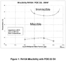
- Figure 1 is a chart illustrating the miscibility of R410A with POE-32 Oil according to Example 15.
- the heat transfer composition of the invention particularly comprises a refrigerant as discussed above and a stabilizer.
- stabilizers include diene-based compounds and/or phenol-based compounds and/or phosphorus compounds and/or nitrogen compounds and/or epoxides selected from the group consisting of aromatic epoxides, alkyl epoxides, alkyenyl epoxides.
- the diene-based compounds are preferably terpenes, which include but are not limited to terebene, retinal, geraniol, terpinene, delta-3 carene, terpinolene, phellandrene, fenchene, myrcene, farnesene, pinene, nerol, citral, camphor, menthol, limonene, nerolidol, phytol, carnosic acid and vitamin A 1 .
- the stabilizer is farnesene.
- the diene based compounds can be provided in the heat transfer composition in an amount of from about 0.001% by weight to about 5% by weight, preferably about 0.01% by weight to about 2% by weight, more preferably from about 0.1 to about 1% by weight. In each case, percentage by weight refers to the weight of the heat transfer composition.
- the stabilizer comprises farnesene and diphenyl phosphite.
- the nitrogen compounds can be provided in the heat transfer composition in an amount of from about 0.001% by weight to about 10% by weight, preferably about 0.01% by weight to about 5% by weight, more preferably from about 0.1 to about 2.5% by weight, and even more preferably from about 1 to about 2.5% by weight. In each case, percentage by weight refers to the weight of the heat transfer composition.
- the stabilizer comprises a phenol, preferably a hindered phenol.
- the phenol can be one or more compounds selected from 4,4'-methylenebis(2,6-di-tert-butylphenol); 4,4'-bis(2,6-di-tert-butylphenol); 2,2- or 4,4-biphenyldiols, including 4,4'-bis(2-methyl-6-tert-butylphenol); derivatives of 2,2- or 4,4-biphenyldiols; 2,2'-methylenebis(4-ethyl-6-tertbutylphenol); 2,2'-methylenebis(4-methyl-6-tert-butylphenol); 4,4-butylidenebis(3-methyl-6-tert-butylphenol); 4,4-isopropylidenebis(2,6-di-tert-butylphenol); 2,2'-methylenebis(4-methyl-6-nonylphenol); 2,4'-methylenebis(4-methyl-6
- the heat transfer composition of the invention can preferably comprise a refrigerant consisting of a blend of the following three compounds, with the following percentages being based on the total weight of the following three compounds: from about 48% by weight to about 51% by weight difluoromethane (HFC-32),
- the lubricants are selected from polyol esters (POEs), polyalkylene glycols (PAGs), mineral oil, alkylbenzenes (ABs) and polyvinyl ethers (PVE), more preferably from polyol esters (POEs), mineral oil, alkylbenzenes (ABs) and polyvinyl ethers (PVE), particularly from polyol esters (POEs), mineral oil and alkylbenzenes (ABs), most preferably from polyol esters (POEs).
- POEs polyol esters
- PAGs polyalkylene glycols
- PEGs polyalkylene glycols
- ABs alkylbenzenes
- PVE polyvinyl ethers
- the heat transfer composition of the invention can preferably comprise a refrigerant consisting of about 50% by weight difluoromethane (HFC-32), about 11.5% by weight pentafluoroethane (HFC-125), and about 38.5% by weight trifluoroiodomethane (CF 3 I) and a stabilizer composition comprising BHT, wherein said BHT is present in an amount of from about 0.001% by weight to about 5 % by weight based on the weight of heat transfer composition and from 10 to 60 wt.% of a polyol ester (POE) lubricant, based on the weight of the heat transfer composition.
- HFC-32 difluoromethane
- HFC-125 pentafluoroethane
- CF 3 I trifluoroiodomethane
- the present invention can further comprise a heat transfer composition as set out below wherein the lubricant is present in an amount of 20 wt% relative to the total amount of refrigerant and lubricant and wherein the mixture has one liquid phase at at least one temperature in the range of -40 °C to +80 °C.
- compositions of the invention are capable of achieving a difficult to achieve combination of properties including particularly low GWP.
- the compositions of the invention have a Global Warming Potential (GWP) of not greater than about 1500, preferably not greater than about 1000, more preferably not greater than about 750.
- GWP Global Warming Potential
- the composition of the invention has a Global Warming Potential (GWP) of not greater than about 750.
- the heat transfer composition of the invention can be used in heating and cooling applications.
- the present invention therefore provides the use of a heat transfer composition
- a heat transfer composition comprising a refrigerant, said refrigerant consisting of a blend of three compounds, said blend consisting of:
- the stabilizer composition can comprise farnesene, diphenyl phosphite and BHT.
- the stabilizer composition can comprise BHT.
- the stabilizer composition consists essentially of farnesene, diphenyl phosphite and BHT.
- the stabilizer composition consists essentially of BHT.
- the stabilizer composition consists of farnesene, diphenyl phosphite and BHT.
- the stabilizer composition consists of BHT.
Description
- The present invention relates to compositions, methods and systems having utility in heat exchange systems, including air conditioning and refrigeration applications and in particular aspects to compositions useful in heat transfer systems of the type in which the refrigerant R-410A would have been used, that is as a replacement of the refrigerant R-410A for heating and cooling applications and to retrofitting heat exchange systems, including systems designed for use with R-410A.
- Mechanical refrigeration systems, and related heat transfer devices, such as heat pumps and air conditioners are well known in the art for industrial, commercial and domestic uses. Chlorofluorocarbons (CFCs) were developed in the 1930s as refrigerants for such systems. However, since the 1980s, the effect of CFCs on the stratospheric ozone layer has become the focus of much attention. In 1987, a number of governments signed the Montreal Protocol to protect the global environment, setting forth a timetable for phasing out the CFC products. CFCs were replaced with more environmentally acceptable materials that contain hydrogen, namely the hydrochlorofluorocarbons (HCFCs).
- One of the most commonly used hydrochlorofluorocarbon refrigerants was chlorodifluoromethane (HCFC-22). However, subsequent amendments to the Montreal protocol accelerated the phase out of the CFCs and also scheduled the phase-out of HCFCs, including HCFC-22.
- In response to the requirement for a non-flammable, non-toxic alternative to the CFCs and HCFCs, industry has developed a number of hydrofluorocarbons (HFCs) which have zero ozone depletion potential. R-410A (a 50:50 w/w blend of difluoromethane (HFC-32) and pentafluoroethane (HFC-125)) was adopted as the industry replacement for HCFC-22 in air conditioning and chiller applications as it does not contribute to ozone depletion. However, R-410A is not a drop-in replacement for R-22. Thus, the replacement of R-22 with R-410A required the redesign of major components within heat exchange systems, including the replacement and redesign of the compressor to accommodate the higher operating pressure and volumetric capacity of R-410A, when compared with R-22.
- While R-410A has a more acceptable Ozone Depleting Potential (ODP) than R-22, the continued use of R-410A is problematic, due to it's high Global Warming Potential of 2088. There is therefore a need in the art for the replacement of R-410A with a more environmentally acceptable alternative.
- It is understood in the art that it is highly desirable for a replacement heat transfer fluid to possess a difficult to achieve mosaic of properties including excellent heat transfer properties and in particular heat transfer properties that are well matched to the needs of the particular application, chemical stability, low or no toxicity, non-flammability, lubricant miscibility and/or lubricant compatibility amongst others. In addition, any replacement for R-410A would ideally be a good match for the operating conditions of R-410A in order to avoid modification or redesign of the system. The development of a heat transfer fluid meeting all of these requirements, many of which are unpredictable is a significant challenge.
- With regard to efficiency in use, it is important to note that a loss of refrigerant thermodynamic performance or energy efficiency may result in an increase in fossil fuel usage as a result of the increased demand for electrical energy. The use of such a refrigerant will therefore have a negative secondary environmental impact.
- Flammability is considered to be an important, and in some cases, a critical property for many heat transfer applications. Thus, it is frequently beneficial to use compounds in such compositions to achieve, if possible a refrigerant, which is non-flammable. As used herein, the term "non-flammable" refers to compositions which are determined to be non-flammable in accordance with ASTM standard E-681-2001 at conditions described in ASHRAE Standard 34-2013 and described in Appendix B1 to ASHRAE Standard 34-2013.
- It is critical for maintenance of system efficiency, and proper and reliable functioning of the compressor, that lubricant circulating in a vapour compression heat transfer system is returned to the compressor to perform its intended lubricating function. Otherwise, lubricant might accumulate and become lodged in the coils and piping of the system, including in the heat transfer components. Furthermore, when lubricant accumulates on the inner surfaces of the evaporator, it lowers the heat exchange efficiency of the evaporator, and thereby reduces the efficiency of the system.
- R-410A is currently used with polyol ester (POE) lubricating oil in air conditioning applications, as R-410A is miscible with POE at temperatures experienced during use of such systems. However, R-410A is immiscible with POE at temperatures typically experienced during operation of low temperature refrigeration systems, and heat pump systems. Therefore, unless steps are taken to mitigate against this immiscibility, POE and R-410A cannot be used in low temperature refrigeration or heat pump systems.
- It is therefore desirable to be able to provide compositions which are capable of being used as a replacement for R-410A in air conditioning applications. It is an additional benefit to be able to use the compositions of the invention in for example heat pump and low temperature refrigeration systems, wherein said compositions do not suffer the drawback of immiscibility with POE at temperatures experienced during operation of these systems.
-
US 2010/257881 A1 ,US 2010/044619 A1 andJP H08 277389 A - The present invention provides a refrigerant composition which can be used as a replacement for R-410A and which exhibits the desired mosaic of properties of excellent heat transfer properties, chemical stability, low or no toxicity, non-flammability, lubricant miscibility and/or lubricant compatibility in combination with an acceptable Global Warming Potential (GWP).
- According to the present invention, the refrigerant consists of:
- from 48% by weight to 51% by weight difluoromethane (HFC-32),
- from 9.5% by weight to 11.5% by weight pentafluoroethane (HFC-125), and
- from 36.5% by weight to 40.5% by weight trifluoroiodomethane (CF3I), with the percentages being based on the total weight of these three compounds and wherein the amount of each compound can vary by an amount of ± 2% by weight, preferably ± 1% by weight, more preferably ± 0.5% by weight.
- Also according to the present invention, the refrigerant consists of:
- 50% by weight difluoromethane (HFC-32),
- 11.5% by weight pentafluoroethane (HFC-125), and
- 38.5% by weight trifluoroiodomethane (CF3I), with the percentages being based on the total weight of these three compounds and wherein the amount of each compound can vary by an amount of ± 2% by weight, preferably ± 1% by weight, more preferably ± 0.5% by weight.
-
Figure 1 is a chart illustrating the miscibility of R410A with POE-32 Oil according to Example 15. - Applicants have found that the refrigerant of the present invention is capable of providing exceptionally advantageous properties in connection with a combination of two or more properties selected from: heat transfer properties, chemical stability, low or no toxicity, non-flammability and/or lubricant compatibility in combination with an acceptable Global Warming Potential (GWP), especially in connection with the use of the refrigerant of the present invention as a replacement for R-410A.
- For the purposes of this invention, the term "about" in relation to the amounts expressed in weight percent means that the amount of the component can vary by an amount of +/- 2% by weight, preferably +/- 1% by weight, more preferably 0.5% by weight. The term "about", in relation to temperatures means that the stated temperature can vary by an amount of +/-5°C, preferably +/- 2°C and more preferably +/- 1°C, most preferably +/- 0.5°C.
- A particular advantage of the refrigerants of the present invention is that they are non-flammable when tested in accordance with ASTM E681-2009 test procedure as required in ASHRAE Standard 34-2013 and described in Appendix B1 to ASHRAE Standard 34-2013.
- Flammability is defined as the ability of a composition to ignite and/or propagate a flame. It will be appreciated by the skilled person that the flammability of a refrigerant is an important characteristic for use in many important heat transfer applications. Thus, it is a desire in the art to provide a refrigerant composition which can be used as a replacement for R-410A which has excellent heat transfer properties, chemical stability, low or no toxicity, and/or lubricant compatibility and which maintains non-flammability in use. This requirement is met by the refrigerants of the present invention.
- The refrigerant can be incorporated into a heat transfer composition. There is provided heat transfer compositions, methods and systems which utilize in a heat transfer system that is useful with the refrigerant R-410A a refrigerant that has the important characteristic of at once providing in said system and/or in connection with said methods a refrigerant that:
- (a) has an efficiency (COP) from about 95% to about 105%, preferably about 100% to about 105% of the efficiency of R410A in said system and/or used in said method; and
- (b) is non-flammable as determined in accordance with ASTM E681-2009 test procedure as required in ASHRAE Standard 34-2013 and described in Appendix B1 to ASHRAE Standard 34-2013; such refrigerant consists of:
- from about 48% by weight to about 51% by weight difluoromethane (HFC-32),
- from about 9.5% by weight to about 11.5% by weight pentafluoroethane (HFC-125), and
- from about 36.5% by weight to about 40.5% by weight trifluoroiodomethane (CF3I).
- There is provided heat transfer compositions, methods and systems which utilize in a heat transfer system that is useful with the refrigerant R-410A a refrigerant that has the important characteristic of at once providing in said system and/or in connection with said methods a refrigerant that:
- (a) has an efficiency (COP) from about 95% to about 105%, preferably about 100% to about 105% of the efficiency of R410A in said system and/or used in said method;
- (b) has a capacity from about 95% to about 105%, preferably about 98% to about 105% of the capacity of R410A in said system and/or used in said method; and
- (c) is non-flammable as determined in accordance with ASTM E681-2009 test procedure as required in ASHRAE Standard 34-2013 and described in Appendix B1 to ASHRAE Standard 34-2013; such refrigerant consists of:
- from about 48% by weight to about 51% by weight difluoromethane (HFC-32),
- from about 9.5% by weight to about 11.5% by weight pentafluoroethane (HFC-125), and
- from about 36.5% by weight to about 40.5% by weight trifluoroiodomethane (CF3I).
- There is provided heat transfer compositions, methods and systems which utilize in a heat transfer system that is useful with the refrigerant R-410A a refrigerant that has the important characteristic of at once providing in said system and/or in connection with said methods a refrigerant that:
- (a) has an efficiency (COP) from about 95% to about 105%, preferably about 100% to about 105% of the efficiency of R410A in said system and/or used in said method;
- (b) has a capacity from about 95% to about 105%, preferably about 98% to about 105% of the capacity of R410A in said system and/or used in said method;
- (c) is non-flammable as determined in accordance with ASTM E681-2009 test procedure as required in ASHRAE Standard 34-2013 and described in Appendix B1 to ASHRAE Standard 34-2013;
- (d) produces in the system and/or the methods a compressor discharge temperature that is not greater than 10°C higher than that of R-410A; and
- (e) produces in the system and/or the methods a compressor pressure ratio that is from about 95% to about 105% of the compressor pressure ratio of R-410A; such refrigerant consists of:
- from about 48% by weight to about 51% by weight difluoromethane (HFC-32),
- from about 9.5% by weight to about 11.5% by weight pentafluoroethane (HFC-125), and
- from about 36.5% by weight to about 40.5% by weight trifluoroiodomethane (CF3I).
- The refrigerant can be incorporated into a heat transfer composition. Preferably, and according to the present invention the heat transfer composition comprises a refrigerant which consists of a blend of the following three compounds, with the following percentages being based on the total weight of the following three compounds::
- from about 48% by weight to about 51% by weight difluoromethane (HFC-32),
- from about 9.5% by weight to about 11.5% by weight pentafluoroethane (HFC-125), and
- from about 36.5% by weight to about 40.5% by weight trifluoroiodomethane (CF3I).
- More preferably, and according to the present invention, the heat transfer composition comprises a refrigerant which consists of a blend of the following three compounds, with the following percentages being based on the total weight of the following three compounds:
- about 50% by weight difluoromethane (HFC-32),
- about 11.5% by weight pentafluoroethane (HFC-125), and
- about 38.5% by weight trifluoroiodomethane (CF3I).
- Preferably, the heat transfer composition comprises the refrigerant in an amount of greater than 40% by weight of the heat transfer composition or greater than about 50% by weight of the heat transfer composition, or greater than 70% by weight of the heat transfer composition, or greater than 80% by weight of the heat transfer composition or greater than 90% by weight of the heat transfer composition. The heat transfer composition may consist essentially of the refrigerant.
- The heat transfer compositions of the invention may include other components for the purpose of enhancing or providing certain functionality to the compositions. Such other components or additives may include one or more of lubricants, dyes, solubilizing agents, compatibilizers, stabilizers, antioxidants, corrosion inhibitors, extreme pressure additives and anti wear additives.
- The heat transfer composition of the invention particularly comprises a refrigerant as discussed above and a stabilizer. Examples of preferred stabilizers include diene-based compounds and/or phenol-based compounds and/or phosphorus compounds and/or nitrogen compounds and/or epoxides selected from the group consisting of aromatic epoxides, alkyl epoxides, alkyenyl epoxides.
- The stabilizer preferably is provided in the heat transfer composition in an amount of from about 0.001% by weight to about 5 % by weight, preferably about 0.01% by weight to about 2% by weight, more preferably from about 0.1 to about 1% by weight. In each case, percentage by weight refers to the weight of the heat transfer composition.
- The diene-based compounds include C3 to C15 dienes and to compounds formed by reaction of any two or more C3 to C4 dienes. Preferably, the diene based compounds are selected from the group consisting of allyl ethers, propadiene, butadiene, isoprene and terpenes. The diene-based compounds are preferably terpenes, which include but are not limited to terebene, retinal, geraniol, terpinene, delta-3 carene, terpinolene, phellandrene, fenchene, myrcene, farnesene, pinene, nerol, citral, camphor, menthol, limonene, nerolidol, phytol, carnosic acid and vitamin A1. Preferably, the stabilizer is farnesene.
- Preferred terpene stabilizers are disclosed in
US Provisional Patent Application No. 60/638,003 filed on December 12, 2004 - The diene based compounds can be provided in the heat transfer composition in an amount of from about 0.001% by weight to about 10 % by weight, preferably about 0.01% by weight to about 5% by weight more preferably from about 0.1 to about 2.5% by weight, and even more preferably from about 1 to about 2.5% by weight. In each case, percentage by weight refers to the weight of the heat transfer composition.
- In addition, the diene based compounds can be provided in the heat transfer composition in an amount of from about 0.001% by weight to about 5% by weight, preferably about 0.01% by weight to about 2% by weight, more preferably from about 0.1 to about 1% by weight. In each case, percentage by weight refers to the weight of the heat transfer composition.
- The diene based compounds are preferably provided in combination with a phosphorous compound.
- The phosphorus compound can be a phosphite or a phosphate compound. For the purposes of this invention, the phosphite compound can be a diaryl, dialkyl, triaryl and/or trialkyl phosphite, in particular one or more compounds selected from hindered phosphites, tris-(di-tert-butylphenyl)phosphite, di-n-octyl phophite, iso-decyl diphenyl phosphite, triphenyl phosphite and diphenyl phosphite, particularly diphenyl phosphite.
- The phosphate compounds can be a triaryl phosphate, trialkyl phosphate, alkyl mono acid phosphate, aryl diacid phosphate, amine phosphate, preferably triaryl phosphate and/or a trialkyl phosphate, particularly tri-n-butyl phosphate.
- Preferably the stabilizer comprises farnesene and diphenyl phosphite.
- The phosphorus compounds can be provided in the heat transfer composition in an amount of from about 0.001% by weight to about 10% by weight, more preferably about 0.01 % by weight to about 5% by weight and even more preferably from about 0.1 to about 2.5% by weight, and even more preferably from about 1 to about 2.5% by weight. In each case, by weight refers to weight of the heat transfer composition.
In addition, the phosphorus compounds can be provided in the heat transfer composition in an amount of from about 0.001% by weight to about 5% by weight, preferably about 0.01% by weight to about 2% by weight, more preferably from about 0.1 to about 1% by weight. In each case, by weight refers to weight of the heat transfer composition. - Additionally, the heat transfer composition of the invention comprises a refrigerant consisting of a blend of the following three compounds, with the following percentages being based on the total weight of the following three compounds: from about 48% by weight to about 51% by weight difluoromethane (HFC-32), from about 9.5% by weight to about 11.5% by weight pentafluoroethane (HFC-125), and from about 36.5% by weight to about 40.5% by weight trifluoroiodomethane (CF3I) and a stabilizer composition comprising a terpene and a phosphorus compound. The phosphorus compound is preferably selected from a phosphate or a phosphite. Preferably, the stabilizer in such composition comprises a terpene and a phosphite, more preferably farnesene and diphenyl phosphite.
- Additionally, the heat transfer composition of the invention can comprise a refrigerant consisting of a blend of the following three compounds, with the following percentages being based on the total weight of the following three compounds: about 50% by weight difluoromethane (HFC-32), about 11.5% by weight pentafluoroethane (HFC-125), and about 38.5% by weight trifluoroiodomethane (CF3I) and a stabilizer composition comprising a terpene and a phosphorus compound selected from a phosphate or a phosphite. The phosphorus compound is preferably selected from a phosphate or a phosphite. Preferably, the stabilizer in such composition comprises a terpene and a phosphite, more preferably farnesene and diphenyl phosphite.
- Preferably, the heat transfer composition comprises a refrigerant as set out above and a stabilizer composition comprising farnesene and a phosphorous compound selected from a diaryl phosphite, a dialkyl phosphite, a triaryl phosphate or a trialkyl phosphate, more preferably diphenyl phosphite and/or tri-n-butyl phosphate. More preferably the heat transfer composition comprises a refrigerant as described herein and a stabilizer composition comprising farnesene and one or more of a diaryl phosphite or a dialkyl phosphite, more preferably diphenyl phosphite.
- Alternatively, or in addition, the stabilizer is a nitrogen compound. For the purposes of this invention, the nitrogen compound can be one or more compounds selected from dinitrobenzene, nitrobenzene, nitromethane, nitrosobenzene, and TEMPO [(2,2,6,6-tetramethylpiperidin-1-yl)oxyl]. Preferably, the stabilizer is dinitrobenzene.
- Alternatively, or in addition, the nitrogen compound comprises an amine based compound. For the purposes of this invention, the amine based compound can be one or more secondary or tertiary amines selected from diphenylamine, p-phenylenediamine, triethylamine, tributylamine, diisopropylamine, triisopropylamine and triisobutylamine. For the purposes of this invention, the amine based compound can be an amine antioxidant such as a substituted piperidine compound, i.e. a derivative of an alkyl substituted piperidyl, piperidinyl, piperazinone, or alkyoxypiperidinyl, particularly one or more amine antioxidants selected from 2,2,6,6-tetramethyl-4-piperidone, 2,2,6,6-tetramethyl-4-piperidinol; bis-(1,2,2,6,6-pentamethylpiperidyl)sebacate; di(2,2,6,6-tetramethyl-4-piperidyl)sebacate, poly(N-hydroxyethyl-2,2,6,6-tetramethyl-4-hydroxy-piperidyl succinate; alkylated paraphenylenediamines such as N-phenyl-N'-(1,3-dimethyl-butyl)-p-phenylenediamine or N,N'-di-sec-butyl-p-phenylenediamine and hydroxylamines such as tallow amines, methyl bis tallow amine and bis tallow amine, or phenol-alpha-napththylamine or Tinuvin ® 765 (Ciba), BLS ® 1944 (Mayzo Inc) and BLS ® 1770 (Mayzo Inc). For the purposes of this invention, the amine based compound can be an alkyldiphenyl amine such as bis (nonylphenyl amine) or a dialkylamine such as (N-(1-methylethyl)-2-propylamine. Alternatively, or in addition, the amine based compound can be one or more of phenyl-alpha-naphthyl amine (PANA), alkyl-phenyl-alpha-naphthyl-amine (APANA) and bis (nonylphenyl) amine. Preferably the amine based compound is one or more of phenyl-alpha-naphthyl amine (PANA), alkyl-phenyl-alpha-naphthyl-amine (APANA) and bis (nonylphenyl) amine, more preferably phenyl-alpha-naphthyl amine (PANA).
- The nitrogen compounds can be provided in the heat transfer composition in an amount of from about 0.001% by weight to about 10% by weight, preferably about 0.01% by weight to about 5% by weight, more preferably from about 0.1 to about 2.5% by weight, and even more preferably from about 1 to about 2.5% by weight. In each case, percentage by weight refers to the weight of the heat transfer composition.
- In addition, the nitrogen compounds can be provided in the heat transfer composition in an amount of from about 0.001% by weight to about 5% by weight, preferably about 0.01% by weight to about 2% by weight, more preferably from about 0.1 to about 1% by weight. In each case, percentage by weight refers to the weight of the heat transfer composition.
- The heat transfer composition of the invention can comprise a refrigerant consisting of a blend of the following three compounds, with the following percentages being based on the total weight of the following three compounds: from about 48% by weight to about 51% by weight difluoromethane (HFC-32), from about 9.5% by weight to about 11.5% by weight pentafluoroethane (HFC-125), and from about 36.5% by weight to about 40.5% by weight trifluoroiodomethane (CF3I) and a stabilizer composition comprising a nitrogen compound selected from dinitrobenzene, nitrobenzene, nitromethane, nitrosobenzene, and TEMPO [(2,2,6,6-tetramethylpiperidin-1-yl)oxyl]; a secondary or tertiary amine selected from diphenylamine, p-phenylenediamine, triethylamine, tributylamine, diisopropylamine, triisopropylamine and triisobutylamine; an amine antioxidant such as a substituted piperidine compound, i.e. a derivative of an alkyl substituted piperidyl, piperidinyl, piperazinone, or alkyoxypiperidinyl, selected from 2,2,6,6-tetramethyl-4-piperidone, 2,2,6,6-tetramethyl-4-piperidinol; bis-(1,2,2,6,6-pentamethylpiperidyl)sebacate; di(2,2,6,6-tetramethyl-4-piperidyl)sebacate, poly(N-hydroxyethyl-2,2,6,6-tetramethyl-4-hydroxy-piperidyl succinate; alkylated paraphenylenediamines such as N-phenyl-N'-(1,3-dimethyl-butyl)-p-phenylenediamine or N,N'-di-sec-butyl-p-phenylenediamine and hydroxylamines such as tallow amines, methyl bis tallow amine and bis tallow amine, or phenol-alpha-napththylamine or Tinuvin ® 765 (Ciba), BLS ® 1944 (Mayzo Inc) and BLS ® 1770 (Mayzo Inc); an alkyldiphenyl amine such as bis (nonylphenyl amine) a dialkylamine such as (N-(1-methylethyl)-2-propylamine or phenyl-alpha-naphthyl amine (PANA), alkyl-phenyl-alpha-naphthyl-amine (APANA) and bis (nonylphenyl) amine, preferably phenyl-alpha-naphthyl amine (PANA), alkyl-phenyl-alpha-naphthyl-amine (APANA) and bis (nonylphenyl) amine, more preferably phenyl-alpha-naphthyl amine (PANA).
- The heat transfer composition of the invention can comprise a refrigerant consisting of a blend of the following three compounds, with the following percentages being based on the total weight of the following three compounds: about 50% by weight difluoromethane (HFC-32), about 11.5% by weight pentafluoroethane (HFC-125), and about 38.5% by weight trifluoroiodomethane (CF3I) and a stabilizer composition comprising a nitrogen compound selected from dinitrobenzene, nitrobenzene, nitromethane, nitrosobenzene, and TEMPO [(2,2,6,6-tetramethylpiperidin-1-yl)oxyl] a secondary or tertiary amine selected from diphenylamine, p-phenylenediamine, triethylamine, tributylamine, diisopropylamine, triisopropylamine and triisobutylamine; an amine antioxidant such as a substituted piperidine compound, i.e. a derivative of an alkyl substituted piperidyl, piperidinyl, piperazinone, or alkyoxypiperidinyl, selected from 2,2,6,6-tetramethyl-4-piperidone, 2,2,6,6-tetramethyl-4-piperidinol; bis-(1,2,2,6,6-pentamethylpiperidyl)sebacate; di(2,2,6,6-tetramethyl-4-piperidyl)sebacate, poly(N-hydroxyethyl-2,2,6,6-tetramethyl-4-hydroxy-piperidyl succinate; alkylated paraphenylenediamines such as N-phenyl-N'-(1,3-dimethyl-butyl)-p-phenylenediamine or N,N'-di-sec-butyl-p-phenylenediamine and hydroxylamines such as tallow amines, methyl bis tallow amine and bis tallow amine, or phenol-alpha-napththylamine or Tinuvin ® 765 (Ciba), BLS ® 1944 (Mayzo Inc) and BLS ® 1770 (Mayzo Inc); an alkyldiphenyl amine such as bis (nonylphenyl amine) a dialkylamine such as (N-(1-methylethyl)-2-propylamine or phenyl-alpha-naphthyl amine (PANA), alkyl-phenyl-alpha-naphthyl-amine (APANA) and bis (nonylphenyl) amine, preferably phenyl-alpha-naphthyl amine (PANA), alkyl-phenyl-alpha-naphthyl-amine (APANA) and bis (nonylphenyl) amine, more preferably phenyl-alpha-naphthyl amine (PANA) or preferably, the nitrogen compound is dinitrobenzene.
- Alternatively, or in addition, the stabilizer comprises a phenol, preferably a hindered phenol. For the purposes of this invention, the phenol can be one or more compounds selected from 4,4'-methylenebis(2,6-di-tert-butylphenol); 4,4'-bis(2,6-di-tert-butylphenol); 2,2- or 4,4-biphenyldiols, including 4,4'-bis(2-methyl-6-tert-butylphenol); derivatives of 2,2- or 4,4-biphenyldiols; 2,2'-methylenebis(4-ethyl-6-tertbutylphenol); 2,2'-methylenebis(4-methyl-6-tert-butylphenol); 4,4-butylidenebis(3-methyl-6-tert-butylphenol); 4,4-isopropylidenebis(2,6-di-tert-butylphenol); 2,2'-methylenebis(4-methyl-6-nonylphenol); 2,2'-isobutylidenebis(4,6-dimethylphenol); 2,2'-methylenebis(4-methyl-6-cyclohexylphenol); 2,6-di-tert-butyl-4-methylphenol (BHT); 2,6-di-tert-butyl-4-ethylphenol: 2,4-dimethyl-6-tert-butylphenol; 2,6-di-tert-alpha-dimethylamino-p-cresol; 2,6-di-tert-butyl-4(N,N'-dimethylaminomethylphenol); 4,4'-thiobis(2-methyl-6-tert-butylphenol); 4,4'-thiobis(3-methyl-6-tert-butylphenol); 2,2'-thiobis(4-methyl-6-tert-butylphenol); bis(3-methyl-4-hydroxy-5-tert-butylbenzyl) sulfide; bis (3,5-di-tert-butyl-4-hydroxybenzyl)sulfide, tocopherol, hydroquinone, 2,2'6,6'-tetra-tert-butyl-4,4'-methylenediphenol and t-butyl hydroquinone, preferably BHT
- The phenol compounds can be provided in the heat transfer composition in an amount of from about 0.001% by weight to about 5 % by weight, preferably about 0.01% by weight to about 2% by weight, more preferably from about 0.1 to about 1% by weight. In each case, by percentage weight refers to the weight of the heat transfer composition.
- Alternatively, the phenol compounds can be provided in the heat transfer composition in an amount of from about 0.001% by weight to about 5 % by weight, preferably about 0.005% by weight to about 2% by weight, more preferably from about 0.01 to about 1% by weight. In each case, percentage by weight refers to the weight of the heat transfer composition.
- Additionally, the heat transfer composition of the invention comprises a refrigerant consisting of a blend of the following three compounds, with the following percentages being based on the total weight of the following three compounds: from about 48% by weight to about 51% by weight difluoromethane (HFC-32), from about 9.5% by weight to about 11.5% by weight pentafluoroethane (HFC-125), and from about 36.5% by weight to about 40.5% by weight trifluoroiodomethane (CF3I) and a stabilizer composition comprising a phenol compound selected from 4,4'-methylenebis(2,6-di-tert-butylphenol); 4,4'-bis(2,6-di-tertbutylphenol); 2,2- or 4,4-biphenyldiols, including 4,4'-bis(2-methyl-6-tert-butylphenol); derivatives of 2,2- or 4,4-biphenyldiols; 2,2'-methylenebis(4-ethyl-6-tertbutylphenol); 2,2'-methylenebis(4-methyl-6-tert-butylphenol); 4,4-butylidenebis(3-methyl-6-tert-butylphenol); 4,4-isopropylidenebis(2,6-di-tert-butylphenol); 2,2'-methylenebis(4-methyl-6-nonylphenol); 2,2'-isobutylidenebis(4,6-dimethylphenol); 2,2'-methylenebis(4-methyl-6-cyclohexylphenol); 2,6-di-tert-butyl-4-methylphenol (BHT); 2,6-di-tert-butyl-4-ethylphenol: 2,4-dimethyl-6-tertbutylphenol; 2,6-di-tert-alpha-dimethylamino-p-cresol; 2,6-di-tert-butyl-4(N,N'-dimethylaminomethylphenol); 4,4'-thiobis(2-methyl-6-tert-butylphenol); 4,4'-thiobis(3-methyl-6-tert-butylphenol); 2,2'-thiobis(4-methyl-6-tert-butylphenol); bis(3-methyl-4-hydroxy-5-tert-butylbenzyl) sulfide; bis (3,5-di-tert-butyl-4-hydroxybenzyl)sulfide, tocopherol, hydroquinone, 2,2'6,6'-tetra-tert-butyl-4,4'-methylenediphenol and t-butyl hydroquinone, preferably BHT
- The heat transfer composition of the invention comprises a refrigerant consisting of a blend of the following three compounds, with the following percentages being based on the total weight of the following three compounds: about 50% by weight difluoromethane (HFC-32), about 11.5% by weight pentafluoroethane (HFC-125), and about 38.5% by weight trifluoroiodomethane (CF3I) and a stabilizer composition comprising a phenol compound selected from 4,4'-methylenebis(2,6-di-tert-butylphenol); 4,4'-bis(2,6-di-tert-butylphenol); 2,2- or 4,4-biphenyldiols, including 4,4'-bis(2-methyl-6-tert-butylphenol); derivatives of 2,2- or 4,4-biphenyldiols; 2,2'-methylenebis(4-ethyl-6-tertbutylphenol); 2,2'-methylenebis(4-methyl-6-tert-butylphenol); 4,4-butylidenebis(3-methyl-6-tert-butylphenol); 4,4-isopropylidenebis(2,6-di-tert-butylphenol); 2,2'-methylenebis(4-methyl-6-nonylphenol); 2,2'-isobutylidenebis(4,6-dimethylphenol); 2,2'-methylenebis(4-methyl-6-cyclohexylphenol); 2,6-di-tert-butyl-4-methylphenol (BHT); 2,6-di-tert-butyl-4-ethylphenol: 2,4-dimethyl-6-tertbutylphenol; 2,6-di-tert-alpha-dimethylamino-p-cresol; 2,6-di-tert-butyl-4(N,N'-dimethylaminomethylphenol); 4,4'-thiobis(2-methyl-6-tert-butylphenol); 4,4'-thiobis(3-methyl-6-tert-butylphenol); 2,2'-thiobis(4-methyl-6-tert-butylphenol); bis(3-methyl-4-hydroxy-5-tert-butylbenzyl) sulfide; bis (3,5-di-tert-butyl-4-hydroxybenzyl)sulfide, tocopherol, hydroquinone, 2,2'6,6'-tetra-tert-butyl-4,4'-methylenediphenol and t-butyl hydroquinone, preferably BHT
- The heat transfer composition of the invention can preferably comprise a refrigerant consisting of a blend of the following three compounds, with the following percentages being based on the total weight of the following three compounds: from about 48% by weight to about 51% by weight difluoromethane (HFC-32),
- from about 9.5% by weight to about 11.5% by weight pentafluoroethane (HFC-125), and
- from about 36.5% by weight to about 40.5% by weight trifluoroiodomethane (CF3I) and a stabilizer composition comprising BHT, wherein said BHT is present in an amount of from about 0.001% by weight to about 5 % by weight based on the weight of heat transfer composition.
- The heat transfer composition of the invention can preferably comprise a refrigerant consisting of a blend of the following three compounds, with the following percentages being based on the total weight of the following three compounds: about 50% by weight difluoromethane (HFC-32), about 11.5% by weight pentafluoroethane (HFC-125), and about 38.5% by weight trifluoroiodomethane (CF3I) and a stabilizer composition comprising BHT, wherein said BHT is present in an amount of from about 0.001% by weight to about 5 % by weight based on the weight of heat transfer composition.
- The heat transfer composition of the invention can preferably comprise a refrigerant consisting of a blend of the following three compounds, with the following percentages being based on the total weight of the following three compounds: from about 48% by weight to about 51% by weight difluoromethane (HFC-32),
- from about 9.5% by weight to about 11.5% by weight pentafluoroethane (HFC-125), and
- from about 36.5% by weight to about 40.5% by weight trifluoroiodomethane (CF3I) and a stabilizer composition consisting essentially of BHT, wherein said BHT is present in an amount of from about 0.001% by weight to about 5 % by weight based on the weight of heat transfer composition.
- The heat transfer composition of the invention can preferably comprise a refrigerant consisting of a blend of the following three compounds, with the following percentages being based on the total weight of the following three compounds: about 50% by weight difluoromethane (HFC-32), about 11.5% by weight pentafluoroethane (HFC-125), and about 38.5% by weight trifluoroiodomethane (CF3I) and a stabilizer composition consisting essentially of BHT, wherein said BHT is present in an amount of from about 0.001% by weight to about 5 % by weight based on the weight of heat transfer composition.
- The heat transfer composition of the invention can preferably comprise a refrigerant consisting of a blend of the following three compounds, with the following percentages being based on the total weight of the following three compounds: from about 48% by weight to about 51% by weight difluoromethane (HFC-32),
- from about 9.5% by weight to about 11.5% by weight pentafluoroethane (HFC-125), and
- from about 36.5% by weight to about 40.5% by weight trifluoroiodomethane (CF3I) and a stabilizer composition comprising farnesene, diphenyl phosphite and BHT, wherein the farnesene is provided in an amount of from about 0.001% by weight to about 5% by weight based on the weight of the heat transfer composition, the diphenyl phosphite is provided in an amount of from about 0.001% by weight to about 5% by weight based on the weight of the heat transfer composition and the BHT is provided in an amount of from about 0.001% by weight to about 5 % by weight based on the weight of heat transfer composition.
- The heat transfer composition of the invention can preferably comprise a refrigerant consisting of about 50% by weight difluoromethane (HFC-32), about 11.5% by weight pentafluoroethane (HFC-125), and about 38.5% by weight trifluoroiodomethane (CF3I) and a stabilizer composition comprising farnesene, diphenyl phosphite and BHT wherein the farnesene is provided in an amount of from about 0.001% by weight to about 5% by weight based on the weight of the heat transfer composition, the diphenyl phosphite is provided in an amount of from about 0.001% by weight to about 5% by weight based on the weight of the heat transfer composition and the BHT is provided in an amount of from about 0.001% by weight to about 5 % by weight based on the weight of heat transfer composition.
- The heat transfer composition of the invention can preferably comprise a refrigerant consisting of a blend of the following three compounds, with the following percentages being based on the total weight of the following three compounds: from about 48% by weight to about 51% by weight difluoromethane (HFC-32),
- from about 9.5% by weight to about 11.5% by weight pentafluoroethane (HFC-125), and
- from about 36.5% by weight to about 40.5% by weight trifluoroiodomethane (CF3I) and a stabilizer composition consisting essentially of farnesene, diphenyl phosphite and BHT, wherein the farnesene is provided in an amount of from about 0.001% by weight to about 5% by weight based on the weight of the heat transfer composition, the diphenyl phosphite is provided in an amount of from about 0.001% by weight to about 5% by weight based on the weight of the heat transfer composition and the BHT is provided in an amount of from about 0.001% by weight to about 5 % by weight based on the weight of heat transfer composition.
- The heat transfer composition of the invention can preferably comprise a refrigerant consisting of about 50% by weight difluoromethane (HFC-32), about 11.5% by weight pentafluoroethane (HFC-125), and about 38.5% by weight trifluoroiodomethane (CF3I) and a stabilizer composition consisting essentially of farnesene, diphenyl phosphite and BHT wherein the farnesene is provided in an amount of from about 0.001% by weight to about 5% by weight based on the weight of the heat transfer composition, the diphenyl phosphite is provided in an amount of from about 0.001% by weight to about 5% by weight based on the weight of the heat transfer composition and the BHT is provided in an amount of from about 0.001% by weight to about 5 % by weight based on the weight of heat transfer composition.
- Each of the heat transfer compositions of the invention as defined above may additionally comprise a lubricant. In general, the heat transfer composition comprises a lubricant, in amounts of from about 5 to 60% by weight of the heat transfer composition, preferably about 10 to about 60% by weight of the heat transfer composition, preferably from about 20 to about 50 % by weight of the heat transfer composition, alternatively about 20 to about 40% by weight of the heat transfer composition, alternatively about 20 to about 30 % by weight of the heat transfer composition, alternatively about 30 to about 50% by weight of the heat transfer composition, alternatively about 30 to about 40% by weight of the heat transfer composition. The heat transfer composition may comprise a lubricant, in amounts of from about 5 to about 10% by weight of the heat transfer composition, preferably around about 8 % by weight of the heat transfer composition.
- Commonly used refrigerant lubricants such as polyol esters (POEs), polyalkylene glycols (PAGs), silicone oils, mineral oil, alkylbenzenes (ABs), polyvinyl ethers (PVEs) and poly(alpha-olefin) (PAO) that are used in refrigeration machinery may be used with the refrigerant compositions of the present invention.
- Preferably the lubricants are selected from polyol esters (POEs), polyalkylene glycols (PAGs), mineral oil, alkylbenzenes (ABs) and polyvinyl ethers (PVE), more preferably from polyol esters (POEs), mineral oil, alkylbenzenes (ABs) and polyvinyl ethers (PVE), particularly from polyol esters (POEs), mineral oil and alkylbenzenes (ABs), most preferably from polyol esters (POEs).
- Commercially available mineral oils include Witco LP 250 (registered trademark) from Witco, Suniso 3GS from Witco and Calumet R015 from Calumet. Commercially available alkylbenzene lubricants include Zerol 150 (registered trademark) and Zerol 300 (registered trademark) from Shrieve Chemical. Commercially available esters include neopentyl glycol dipelargonate which is available as Emery 2917 (registered trademark) and Hatcol 2370 (registered trademark). Other useful esters include phosphate esters, di-basic acid esters and fluoro esters.
- For the purposes of this invention, the heat transfer composition can comprise a refrigerant and a stabilizer composition as disclosed above and a lubricant selected from polyol esters (POEs), polyalkylene glycols (PAGs), mineral oil, alkylbenzenes (ABs) and polyvinyl ethers (PVE), more preferably from polyol esters (POEs), mineral oil, alkylbenzenes (ABs) and polyvinyl ethers (PVE), particularly from polyol esters (POEs), mineral oil and alkylbenzenes (ABs), most preferably from polyol esters (POEs).
- A preferred heat transfer composition further comprises a refrigerant consisting of a blend of the following three compounds, with the following percentages being based on the total weight of the following three compounds: from about 48% by weight to about 51% by weight difluoromethane (HFC-32), from about 9.5% by weight to about 11.5% by weight pentafluoroethane (HFC-125), and from about 36.5% by weight to about 40.5% by weight trifluoroiodomethane (CF3I) and from 10 to 60 wt.% of a polyol ester (POE) lubricant, based on the weight of the heat transfer composition.
- A preferred heat transfer composition further comprises a refrigerant consisting of a blend of the following three compounds, with the following percentages being based on the total weight of the following three compounds from about 50% by weight difluoromethane (HFC-32), about 11.5% by weight pentafluoroethane (HFC-125), and about 38.5% by weight trifluoroiodomethane (CF3I) and from 10 to 60 wt.% of a polyol ester (POE) lubricant, based on the weight of the heat transfer composition.
- The heat transfer composition of the invention can preferably comprise a refrigerant consisting of a blend of the following three compounds, with the following percentages being based on the total weight of the following three compounds: from about 48% by weight to about 51% by weight difluoromethane (HFC-32),
- from about 9.5% by weight to about 11.5% by weight pentafluoroethane (HFC-125), and
- from about 36.5% by weight to about 40.5% by weight trifluoroiodomethane (CF3I) and a stabilizer composition comprising BHT, wherein said BHT is present in an amount of from about 0.001% by weight to about 5 % by weight based on the weight of heat transfer composition and from 10 to 60 wt.% of a polyol ester (POE) lubricant, based on the weight of the heat transfer composition.
- The heat transfer composition of the invention can preferably comprise a refrigerant consisting of about 50% by weight difluoromethane (HFC-32), about 11.5% by weight pentafluoroethane (HFC-125), and about 38.5% by weight trifluoroiodomethane (CF3I) and a stabilizer composition comprising BHT, wherein said BHT is present in an amount of from about 0.001% by weight to about 5 % by weight based on the weight of heat transfer composition and from 10 to 60 wt.% of a polyol ester (POE) lubricant, based on the weight of the heat transfer composition.
- The heat transfer composition of the invention can preferably comprise a refrigerant consisting of a blend of the following three compounds, with the following percentages being based on the total weight of the following three compounds: from about 48% by weight to about 51% by weight difluoromethane (HFC-32),
- from about 9.5% by weight to about 11.5% by weight pentafluoroethane (HFC-125), and
- from about 36.5% by weight to about 40.5% by weight trifluoroiodomethane (CF3I) and a stabilizer composition comprising farnesene, diphenyl phosphite and BHT, wherein the farnesene is provided in an amount of from about 0.001% by weight to about 5% by weight based on the weight of the heat transfer composition, the diphenyl phosphite is provided in an amount of from about 0.001% by weight to about 5% by weight based on the weight of the heat transfer composition and the BHT is provided in an amount of from about 0.001% by weight to about 5 % by weight based on the weight of heat transfer composition and from 10 to 60 wt.% of a polyol ester (POE) lubricant, based on the weight of the heat transfer composition
- The heat transfer composition of the invention can preferably comprise a refrigerant consisting of about 50% by weight difluoromethane (HFC-32), about 11.5% by weight pentafluoroethane (HFC-125), and about 38.5% by weight trifluoroiodomethane (CF3I) and a stabilizer composition comprising farnesene, diphenyl phosphite and BHT wherein the farnesene is provided in an amount of from about 0.001% by weight to about 5% by weight based on the weight of the heat transfer composition, the diphenyl phosphite is provided in an amount of from about 0.001% by weight to about 5% by weight based on the weight of the heat transfer composition and the BHT is provided in an amount of from about 0.001% by weight to about 5 % by weight based on the weight of heat transfer composition and from 10 to 60 wt.% of a polyol ester (POE) lubricant, based on the weight of the heat transfer composition.
- Where the compositions of the invention are provided for use in mobile air conditioning, the lubricant is a polyol ester (POE) lubricant or a polyalkylene glycol lubricant, preferably a polyol ester (POE) lubricant. Alternatively, when the compositions of the invention are provided for stationary air conditioning applications, the lubricant is preferably a polyol ester (POE), an alkyl benzene or a mineral oil, more preferably a polyol ester (POE) lubricant. The heat transfer composition of the invention may consist essentially of or consist of a refrigerant, a stabilizer composition and a lubricant as described herein.
- It has surprisingly been discovered that the refrigerant compositions of the invention are miscible with POE lubricants across a desirable and wide range of temperatures, e.g. temperatures of from about -40°C to +80°C. This allows the inventive refrigerant and heat transfer compositions to be used in a wider variety of heat transfer applications than R410A. For example, the inventive refrigerant and heat transfer compositions may be used in refrigeration, air conditioning and heat pump applications.
- The present invention can further comprise a heat transfer composition as set out below wherein the lubricant is present in an amount of 20 wt% relative to the total amount of refrigerant and lubricant and wherein the mixture has one liquid phase across the temperature range of -40 °C to +80 °C.
- The present invention can further comprise a heat transfer composition as set out below wherein the lubricant is present in an amount of 50 wt% relative to the total amount of refrigerant and lubricant and wherein the mixture has one liquid phase across the temperature range of -40 °C to +80 °C.
- In a particularly preferred feature of the present invention, the heat transfer composition comprises a refrigerant as set out above, and a POE lubricant, wherein the lubricant is present in an amount of 5 wt% relative to the total amount of refrigerant and lubricant and wherein the mixture has one liquid phase at at least one temperature in the range of -40 to - 25 °C and/or in the range of +50 to +80 °C.
- In a particularly preferred feature of the present invention, the heat transfer composition comprises a refrigerant as set out above, and a POE lubricant, wherein the lubricant is present in an amount of 20 wt% relative to the total amount of refrigerant and lubricant and wherein the mixture has one liquid phase at at least one temperature in the range of -40 to - 25 °C and/or in the range of +50 to +80 °C.
- In a particularly preferred feature of the present invention, the heat transfer composition comprises a refrigerant as set out above, and a POE lubricant, wherein the lubricant is present in an amount of 50 wt% relative to the total amount of refrigerant and lubricant and wherein the mixture has one liquid phase at at least one temperature in the range of -40 to - 25 °C and/or in the range of +50 to +80 °C.
- In an alternative particularly preferred feature of the present invention, the heat transfer composition comprises a refrigerant as set out above, and a POE lubricant, wherein the lubricant is present in an amount of 5 wt% relative to the total amount of refrigerant and lubricant and wherein the mixture has one liquid phase across the temperature range of -40 to - 25 °C and/or +50 to +80 °C.
- In an alternative particularly preferred feature of the present invention, the heat transfer composition comprises a refrigerant as set out above, and a POE lubricant, wherein the lubricant is present in an amount of 20 wt% relative to the total amount of refrigerant and lubricant and wherein the mixture has one liquid phase across the temperature range of -40 to - 25 °C and/or +50 to +80 °C.
- In an alternative particularly preferred feature of the present invention, the heat transfer composition comprises a refrigerant as set out above, and a POE lubricant, wherein the lubricant is present in an amount of 50 wt% relative to the total amount of refrigerant and lubricant and wherein the mixture has one liquid phase across the temperature range of -40 to - 25 °C and/or +50 to +80 °C.
- The present invention further provides a heat transfer composition comprising a consisting of a blend of the following three compounds, with the following percentages being based on the total weight of the following three compounds:
- from about 48% by weight to about 51% by weight difluoromethane (HFC-32),
- from about 9.5% by weight to about 11.5% by weight pentafluoroethane (HFC-125), and
- from about 36.5% by weight to about 40.5% by weight trifluoroiodomethane (CF3I)
- and a POE lubricant; wherein the lubricant is present in an amount of 5 wt% relative to the total amount of refrigerant and lubricant and wherein the mixture has one liquid phase at at least one temperature in the range of -40 °C to +80 °C.
- The present invention can further comprise a heat transfer composition as set out below wherein the lubricant is present in an amount of 20 wt% relative to the total amount of refrigerant and lubricant and wherein the mixture has one liquid phase at at least one temperature in the range of -40 °C to +80 °C.
- The present invention can further comprise a heat transfer composition as set out below wherein the lubricant is present in an amount of 50 wt% relative to the total amount of refrigerant and lubricant and wherein the mixture has one liquid phase at at least one temperature in the range of -40 °C to +80 °C.
- In a particularly preferred feature of the present invention, the heat transfer composition comprises a refrigerant consisting of a blend of the following three compounds, with the following percentages being based on the total weight of the following three compounds:
- from about 48% by weight to about 51% by weight difluoromethane (HFC-32),
- from about 9.5% by weight to about 11.5% by weight pentafluoroethane (HFC-125), and
- from about 36.5% by weight to about 40.5% by weight trifluoroiodomethane (CF3I)
- and a POE lubricant; wherein the lubricant is present in an amount of 5 wt% relative to the total amount of refrigerant and lubricant and wherein the mixture has one liquid phase across the temperature range of -40 °C to +80 °C.
- The present invention can further comprise a heat transfer composition as set out herein wherein the lubricant is present in an amount of 20 wt% relative to the total amount of refrigerant and lubricant and wherein the mixture has one liquid phase across the temperature range of -40 °C to +80 °C.
- The present invention can further comprise a heat transfer composition as set out herein wherein the lubricant is present in an amount of 50 wt% relative to the total amount of refrigerant and lubricant and wherein the mixture has one liquid phase across the temperature range of -40 °C to +80 °C.
- In a particularly preferred feature of the present invention, the heat transfer composition comprises a refrigerant as set out herein, and a POE lubricant, wherein the lubricant is present in an amount of 5 wt% relative to the total amount of refrigerant and lubricant and wherein the mixture has one liquid phase at at least one temperature in the range of -40 to - 25 °C and/or in the range of +50 to +80 °C.
- In a particularly preferred feature of the present invention, the heat transfer composition comprises a refrigerant as set out herein, and a POE lubricant, wherein the lubricant is present in an amount of 20 wt% relative to the total amount of refrigerant and lubricant and wherein the mixture has one liquid phase at at least one temperature in the range of -40 to - 25 °C and/or in the range of +50 to +80 °C.
- In a particularly preferred feature of the present invention, the heat transfer composition comprises a refrigerant as set out herein, and a POE lubricant, wherein the lubricant is present in an amount of 50 wt% relative to the total amount of refrigerant and lubricant and wherein the mixture has one liquid phase at at least one temperature in the range of -40 to - 25 °C and/or in the range of +50 to +80 °C.
- In an alternative particularly preferred feature of the present invention, the heat transfer composition comprises a refrigerant as set out herein, and a POE lubricant, wherein the lubricant is present in an amount of 5 wt% relative to the total amount of refrigerant and lubricant and wherein the mixture has one liquid phase across the temperature range of -40 to - 25 °C and/or +50 to +80 °C.
- In an alternative particularly preferred feature of the present invention, the heat transfer composition comprises a refrigerant as set out herein, and a POE lubricant, wherein the lubricant is present in an amount of 20 wt% relative to the total amount of refrigerant and lubricant and wherein the mixture has one liquid phase across the temperature range of -40 to - 25 °C and/or +50 to +80 °C.
- In an alternative particularly preferred feature of the present invention, the heat transfer composition comprises a refrigerant as set out herein, and a POE lubricant, wherein the lubricant is present in an amount of 50 wt% relative to the total amount of refrigerant and lubricant and wherein the mixture has one liquid phase across the temperature range of -40 to - 25 °C and/or +50 to +80 °C.
- The present invention further provides a heat transfer composition comprising a refrigerant consisting of a blend of the following three compounds, with the following percentages being based on the total weight of the following three compounds:
- about 50% by weight difluoromethane (HFC-32),
- about 11.5% by weight pentafluoroethane (HFC-125), and
- about 38.5% by weight trifluoroiodomethane (CF3I)
- and a POE lubricant; wherein the lubricant is present in an amount of 5 wt% relative to the total amount of refrigerant and lubricant and wherein the mixture has one liquid phase at at least one temperature in the range of -40 °C to +80 °C.
- The present invention can further comprise a heat transfer composition as set out herein wherein the lubricant is present in an amount of 20 wt% relative to the total amount of refrigerant and lubricant and wherein the mixture has one liquid phase at at least one temperature in the range of -40 °C to +80 °C.
- The present invention can further comprise a heat transfer composition as set out herein wherein the lubricant is present in an amount of 50 wt% relative to the total amount of refrigerant and lubricant and wherein the mixture has one liquid phase at at least one temperature in the range of -40 °C to +80 °C.
- In a particularly preferred feature of the present invention, the heat transfer composition comprises a refrigerant consisting of a blend of the following three compounds, with the following percentages being based on the total weight of the following three compounds:
- about 50% by weight difluoromethane (HFC-32),
- about 11.5% by weight pentafluoroethane (HFC-125), and
- about 38.5% by weight trifluoroiodomethane (CF3I)
- and a POE lubricant; wherein the lubricant is present in an amount of 5 wt% relative to the total amount of refrigerant and lubricant and wherein the mixture has one liquid phase across the temperature range of -40 °C to +80 °C.
- Other additives not mentioned herein can also be included by those skilled in the art in view of the teaching contained herein without departing from the novel and basic features of the present invention.
- Combinations of surfactants and solubilizing agents may also be added to the present compositions to aid oil solubility as disclosed in
US patent No. 6,516,837 . - The applicants have found that the compositions of the invention are capable of achieving a difficult to achieve combination of properties including particularly low GWP. Thus, the compositions of the invention have a Global Warming Potential (GWP) of not greater than about 1500, preferably not greater than about 1000, more preferably not greater than about 750. In a particularly preferred feature of the invention, the composition of the invention has a Global Warming Potential (GWP) of not greater than about 750.
- In addition, the compositions of the invention have a low Ozone Depletion Potential (ODP). Thus, the compositions of the invention have an Ozone Depletion Potential (ODP) of not greater than 0.05, preferably not greater than 0.02, more preferably about zero.
- In addition, the compositions of the invention show acceptable toxicity and preferably have an Occupational Exposure Limit (OEL) of greater than about 400.
- The compositions disclosed herein are provided for use in heat transfer applications, including air conditioning, refrigeration and heat pumps.
- Any reference to the heat transfer composition of the invention refers to each and any of the heat transfer compositions as described herein. Thus, for the following discussion of the uses or applications of the composition of the invention, the heat transfer composition may comprise or consist essentially of any of the refrigerants described herein
- For the purposes of this invention, each and any of the heat transfer compositions as described herein can be used in a heat transfer system, such as an air conditioning system, a refrigeration system or a heat pump. The heat transfer system according to the present invention can comprise a compressor, an evaporator, a condenser and an expansion device, in communication with each other.
- Examples of commonly used compressors, for the purposes of this invention include reciprocating, rotary (including rolling piston and rotary vane), scroll, screw, and centrifugal compressors. Thus, the present invention provides each and any of the refrigerants and/or heat transfer compositions as described herein for use in a heat transfer system comprising a reciprocating, rotary (including rolling piston and rotary vane), scroll, screw, or centrifugal compressor.
- Examples of commonly used expansion devices, for the purposes of this invention include a capillary tube, a fixed orifice, a thermal expansion valve and an electronic expansion valve. Thus, the present invention provides each and any of the refrigerants and/or heat transfer compositions as described herein for use in a heat transfer system comprising a capillary tube, a fixed orifice, a thermal expansion valve or an electronic expansion valve.
- For the purposes of this invention, the evaporator and the condenser together form a heat exchanger, preferably selected from a finned tube heat exchanger, a microchannel heat exchanger, a shell and tube, a plate heat exchanger, and a tube-in-tube heat exchanger. Thus, the present invention provides each and any of the refrigerants and/or heat transfer compositions as described herein for use in a heat transfer system wherein the evaporator and condenser together form a finned tube heat exchanger, a microchannel heat exchanger, a shell and tube, a plate heat exchanger, or a tube-in-tube heat exchanger.
- The heat transfer composition of the invention can be used in heating and cooling applications.
- In a particular feature of the invention, the heat transfer composition can be used in a method of cooling comprising condensing a heat transfer composition and subsequently evaporating said composition in the vicinity of an article or body to be cooled.
- Thus, the invention relates to a method of cooling in a heat transfer system comprising an evaporator, a condenser and a compressor, the process comprising the steps of i) condensing a heat transfer composition as described herein; and
ii) evaporating the composition in the vicinity of body or article to be cooled;
wherein the evaporator temperature of the heat transfer system is in the range of from about -40°C to about +10°C; - Alternatively, or in addition, the heat transfer composition can be used in a method of heating comprising condensing the heat transfer composition in the vicinity of an article or body to be heated and subsequently evaporating said composition.
- Thus, the invention relates to a method of heating in a heat transfer system comprising an evaporator, a condenser and a compressor, the process comprising the steps of i) condensing a heat transfer composition as described herein,
in the vicinity of a body or article to be heated
and
ii) evaporating the composition;
wherein the evaporator temperature of the heat transfer system is in the range of about - 30°C to about 5°C - The heat transfer composition of the invention is provided for use in air conditioning applications including both mobile and stationary air conditioning applications. Thus, any of the heat transfer compositions described herein can be used in any one of:
- an air conditioning application including mobile air conditioning, particularly automobile air conditioning,
- a mobile heat pump, particularly an electric vehicle heat pump;
- a chiller, particularly a positive displacement chiller, more particularly an air cooled or water cooled direct expansion chiller, which is either modular or conventionally singularly packaged,
- a residential air conditioning system, particularly a ducted split or a ductless split air conditioning system,
- a residential heat pump,
- a residential air to water heat pump/hydronic system,
- an industrial air conditioning system
- a commercial air conditioning system, particularly a packaged rooftop unit and a variable refrigerant flow (VRF) system;
- a commercial air source, water source or ground source heat pump system.
- The heat transfer composition of the invention is provided for use in a refrigeration system. The term "refrigeration system" refers to any system or apparatus or any part or portion of such a system or apparatus which employs a refrigerant to provide cooling. Thus, any of the heat transfer compositions described herein can be used in any one of:
- a low temperature refrigeration system,
- a medium temperature refrigeration system,
- a commercial refrigerator,
- a commercial freezer,
- an ice machine,
- a vending machine,
- a transport refrigeration system,
- a domestic freezer,
- a domestic refrigerator,
- an industrial freezer,
- an industrial refrigerator and
- a chiller.
- Each of the heat transfer compositions described herein is particularly provided for use in a residential air-conditioning system (with an evaporator temperature in the range of about 0 to about 10°C, particularly about 7°C for cooling and/or in the range of about -20 to about 3°C, particularly about 0.5°C for heating). Alternatively, or additionally, each of the heat transfer compositions described herein is particularly provided for use in a residential air conditioning system with a reciprocating, rotary (rolling-piston or rotary vane) or scroll compressor.
- Each of the heat transfer compositions described herein is particularly provided for use in an air cooled chiller (with an evaporator temperature in the range of about 0 to about 10°C, particularly about 4.5°C), particularly an air cooled chiller with a positive displacement compressor, more particular an air cooled chiller with a reciprocating scroll compressor.
- Each of the heat transfer compositions described herein is particularly provided for use in a residential air to water heat pump hydronic system (with an evaporator temperature in the range of about -20 to about 3°C, particularly about 0.5°C or with an evaporator temperature in the range of about -30 to about 5°C, particularly about 0.5°C).
- Each of the heat transfer compositions described herein is particularly provided for use in a medium temperature refrigeration system (with an evaporator temperature in the range of about -12 to about 0°C, particularly about -8°C).
- Each of the heat transfer compositions described herein is particularly provided for use in a low temperature refrigeration system (with an evaporator temperature in the range of about - 40 to about -12°C, particularly about -23°C or preferably about -32°C).
- Thus, the heat transfer composition of the invention is provided for use in a residential air conditioning system, wherein the residential air-conditioning system is used to supply cool air (said air having a temperature of for example, about 10°C to about 17°C, particularly about 12°C) to buildings for example, in the summer. Typical system types are split, mini-split, and window, ducted split, ductless split, window, and portable air-conditioning system. The system usually has an air-to-refrigerant evaporator (indoor coil), a compressor, an air-to-refrigerant condenser (outdoor coil), and an expansion valve. The evaporator and condenser are usually a round tube plate fin, a finned tube or microchannel heat exchanger. The compressor is usually a reciprocating or rotary (rolling-piston or rotary vane) or scroll compressor. The expansion valve is usually a capillary tube, thermal or electronic expansion valve. The refrigerant evaporating temperature is preferably in the range of 0 to 10°C. The condensing temperature is preferably in the range of 40 to 70 °C.
- The heat transfer composition of the invention is provided for use in a residential heat pump system, wherein the residential heat pump system is used to supply warm air (said air having a temperature of for example, about 18°C to about 24°C, particularly about 21°C) to buildings in the winter. It is usually the same system as the residential air-conditioning system, while in the heat pump mode the refrigerant flow is reversed and the indoor coil becomes condenser and the outdoor coil becomes evaporator. Typical system types are split and mini-split heat pump system. The evaporator and condenser are usually a round tube plate fin, a finned or microchannel heat exchanger. The compressor is usually a reciprocating or rotary (rolling-piston or rotary vane) or scroll compressor. The expansion valve is usually a thermal or electronic expansion valve. The refrigerant evaporating temperature is preferably in the range of about -20 to about 3°C or about -30 to about 5°C. The condensing temperature is preferably in the range of about 35 to about 50 °C.
- The heat transfer composition of the invention is provided for use in a commercial air-conditioning system wherein the commercial air conditioning system can be a chiller which is used to supply chilled water (said water having a temperature of for example about 7°C) to large buildings such as offices and hospitals, etc. Depending on the application, the chiller system may be running all year long. The chiller system may be air-cooled or water-cooled. The air-cooled chiller usually has a plate, tube-in-tube or shell-and-tube evaporator to supply chilled water, a reciprocating or scroll compressor, a round tube plate fin, a finned tube or microchannel condenser to exchange heat with ambient air, and a thermal or electronic expansion valve. The water-cooled system usually has a shell-and-tube evaporator to supply chilled water, a reciprocating, scroll, screw or centrifugal compressor, a shell-and-tube condenser to exchange heat with water from cooling tower or lake, sea and other natural recourses, and a thermal or electronic expansion valve. The refrigerant evaporating temperature is preferably in the range of about 0 to about 10°C. The condensing temperature is preferably in the range of about 40 to about 70 °C.
- The heat transfer composition of the invention is provided for use in a residential air-to-water heat pump hydronic system, wherein the residential air-to-water heat pump hydronic system is used to supply hot water (said water having a temperature of for example about 50°C or about 55°C) to buildings for floor heating or similar applications in the winter. The hydronic system usually has a round tube plate fin, a finned tube or microchannel evaporator to exchange heat with ambient air, a reciprocating, scroll or rotary compressor, a plate, tube-in-tube or shell-in-tube condenser to heat the water, and a thermal or electronic expansion valve. The refrigerant evaporating temperature is preferably in the range of about -20 to about 3°C, or -30 to about 5°C. The condensing temperature is preferably in the range of about 50 to about 90 °C.
- The heat transfer composition of the invention is provided for use in a medium temperature refrigeration system, wherein the medium temperature refrigeration system is preferably used to chill food or beverages such as in a refrigerator or a bottle cooler. The system usually has an air-to-refrigerant evaporator to chill the food or beverage, a reciprocating, scroll or screw or rotary compressor, an air-to-refrigerant condenser to exchange heat with the ambient air, and a thermal or electronic expansion valve. The refrigerant evaporating temperature is preferably in the range of about -12 to about 0°C. The condensing temperature is preferably in the range of about 40 to about 70 °C, or about 20 to about 70 °C.
- The heat transfer composition of the invention is provided for use in a low temperature refrigeration system, wherein said low temperature refrigeration system is preferably used in a freezer or an ice cream machine. The system usually has an air-to-refrigerant evaporator to chill the food or beverage, a reciprocating, scroll or rotary compressor, an air-to-refrigerant condenser to exchange heat with the ambient air, and a thermal or electronic expansion valve. The refrigerant evaporating temperature is preferably in the range of about -40 to about -12°C. The condensing temperature is preferably in the range of about 40 to about 70 °C, or about 20 to about 70 °C.
- The present invention therefore provides the use of a heat transfer composition comprising a refrigerant, said refrigerant consisting of a blend of three compounds, said blend consisting of:
- about 50% by weight difluoromethane (HFC-32), about 11.5% by weight pentafluoroethane (HFC-125), and about 38.5% by weight trifluoroiodomethane (CF3I)
- wherein the percentages are based on the total weight of the three compounds in the blend; in a chiller.
- The present invention therefore provides the use of a heat transfer composition comprising a refrigerant, said refrigerant consisting of a blend of three compounds, said blend consisting of:
- about 50% by weight difluoromethane (HFC-32), about 11.5% by weight pentafluoroethane (HFC-125), and about 38.5% by weight trifluoroiodomethane (CF3I)
- wherein the percentages are based on the total weight of the three compounds in the blend; and from 10 to 60 wt.% of a polyol ester (POE) lubricant based on the weight of the heat transfer composition, in a chiller.
- The present invention therefore provides the use of a heat transfer composition comprising a refrigerant, said refrigerant consisting of a blend of three compounds, said blend consisting of:
- about 50% by weight difluoromethane (HFC-32), about 11.5% by weight pentafluoroethane (HFC-125), and about 38.5% by weight trifluoroiodomethane (CF3I)
- wherein the percentages are based on the total weight of the three compounds in the blend; and a stabilizer composition comprising farnesene and diphenyl phosphite and/or BHT wherein the farnesene is provided in an amount of from about 0.001% by weight to about 5% by weight based on the weight of the heat transfer composition, the diphenyl phosphate is provided in an amount of from about 0.001% by weight to about 5% by weight based on the weight of the heat transfer composition and the BHT is provided in an amount of from about 0.001% by weight to about 5 % by weight based on the weight of heat transfer composition in a chiller.
- The present invention therefore provides the use of a heat transfer composition comprising a refrigerant, said refrigerant consisting of a blend of three compounds, said blend consisting of:
- about 50% by weight difluoromethane (HFC-32), about 11.5% by weight pentafluoroethane (HFC-125), and about 38.5% by weight trifluoroiodomethane (CF3I)
- wherein the percentages are based on the total weight of the three compounds in the blend; and a stabilizer composition comprising farnesene and diphenyl phosphite and/or BHT wherein the farnesene is provided in an amount of from about 0.001% by weight to about 5% by weight based on the weight of the heat transfer composition, the diphenyl phosphate is provided in an amount of from about 0.001% by weight to about 5% by weight based on the weight of the heat transfer composition and the BHT is provided in an amount of from about 0.001% by weight to about 5 % by weight based on the weight of heat transfer composition and from 10 to 60 wt.% of a polyol ester (POE) lubricant based on the weight of the heat transfer composition, in a chiller.
- The present invention therefore provides the use of a heat transfer composition comprising a refrigerant, said refrigerant consisting of a blend of three compounds, said blend consisting of:
- about 50% by weight difluoromethane (HFC-32), about 11.5% by weight pentafluoroethane (HFC-125), and about 38.5% by weight trifluoroiodomethane (CF3I)
- wherein the percentages are based on the total weight of the three compounds in the blend; in stationary air conditioning, particularly residential air conditioning, industrial air conditioning or commercial air conditioning.
- The present invention therefore provides the use of a heat transfer composition comprising a refrigerant, said refrigerant consisting of a blend of three compounds, said blend consisting of:
- about 50% by weight difluoromethane (HFC-32), about 11.5% by weight pentafluoroethane (HFC-125), and about 38.5% by weight trifluoroiodomethane (CF3I)
- wherein the percentages are based on the total weight of the three compounds in the blend; and from 10 to 60 wt.% of a polyol ester (POE) lubricant based on the weight of the heat transfer composition, in stationary air conditioning, particularly residential air conditioning, industrial air conditioning or commercial air conditioning.
- The present invention therefore provides the use of a heat transfer composition comprising a refrigerant, said refrigerant consisting of a blend of three compounds, said blend consisting of:
- about 50% by weight difluoromethane (HFC-32), about 11.5% by weight pentafluoroethane (HFC-125), and about 38.5% by weight trifluoroiodomethane (CF3I)
- wherein the percentages are based on the total weight of the three compounds in the blend; and a stabilizer composition comprising farnesene and diphenyl phosphite and/or BHT wherein the farnesene is provided in an amount of from about 0.001% by weight to about 5% by weight based on the weight of the heat transfer composition, the diphenyl phosphate is provided in an amount of from about 0.001% by weight to about 5% by weight based on the weight of the heat transfer composition and the BHT is provided in an amount of from about 0.001% by weight to about 5 % by weight based on the weight of heat transfer composition in stationary air conditioning, particularly residential air conditioning, industrial air conditioning or commercial air conditioning.
- The present invention therefore provides the use of a heat transfer composition comprising a refrigerant, said refrigerant consisting of a blend of three compounds, said blend consisting of:
- about 50% by weight difluoromethane (HFC-32), about 11.5% by weight pentafluoroethane (HFC-125), and about 38.5% by weight trifluoroiodomethane (CF3I)
- wherein the percentages are based on the total weight of the three compounds in the blend; and a stabilizer composition comprising farnesene and diphenyl phosphite and/or BHT wherein the farnesene is provided in an amount of from about 0.001% by weight to about 5% by weight based on the weight of the heat transfer composition, the diphenyl phosphate is provided in an amount of from about 0.001% by weight to about 5% by weight based on the weight of the heat transfer composition and the BHT is provided in an amount of from about 0.001% by weight to about 5 % by weight based on the weight of heat transfer composition and from 10 to 60 wt.% of a polyol ester (POE) lubricant based on the weight of the heat transfer composition, in stationary air conditioning, particularly residential air conditioning, industrial air conditioning or commercial air conditioning.
- The present invention therefore provides the use of a heat transfer composition comprising a refrigerant, said refrigerant consisting of a blend of three compounds, said blend consisting of:
- about 50% by weight difluoromethane (HFC-32), about 11.5% by weight pentafluoroethane (HFC-125), and about 38.5% by weight trifluoroiodomethane (CF3I)
- wherein the percentages are based on the total weight of the three compounds in the blend; in commercial refrigeration, particularly in a commercial refrigerator, commercial freezer, an ice machine or a vending machine.
- The present invention therefore provides the use of a heat transfer composition comprising a refrigerant, said refrigerant consisting of a blend of three compounds, said blend consisting of:
- about 50% by weight difluoromethane (HFC-32), about 11.5% by weight pentafluoroethane (HFC-125), and about 38.5% by weight trifluoroiodomethane (CF3I)
- wherein the percentages are based on the total weight of the three compounds in the blend; and from 10 to 60 wt.% of a polyol ester (POE) lubricant based on the weight of the heat transfer composition, in commercial refrigeration, particularly in a commercial refrigerator, commercial freezer, an ice machine or a vending machine.
- Also disclosed herein is the use of a heat transfer composition comprising a refrigerant, said refrigerant comprising at least about 97% by weight of a blend of three compounds, said blend consisting of:
about 46% by weight difluoromethane (HFC-32), about 12% by weight pentafluoroethane (HFC-125), and about 42% by weight trifluoroiodomethane (CF3I) wherein the percentages are based on the total weight of the three compounds in the blend and from 10 to 60 wt.% of a polyol ester (POE) lubricant; based on the weight of the heat transfer composition, in commercial refrigeration, particularly in a commercial refrigerator, commercial freezer, an ice machine or a vending machine. - The present invention therefore provides the use of a heat transfer composition comprising a refrigerant, said refrigerant consisting of a blend of three compounds, said blend consisting of:
- about 50% by weight difluoromethane (HFC-32), about 11.5% by weight pentafluoroethane (HFC-125), and about 38.5% by weight trifluoroiodomethane (CF3I)
- wherein the percentages are based on the total weight of the three compounds in the blend; and a stabilizer composition comprising farnesene and diphenyl phosphite and/or BHT
- wherein the farnesene is provided in an amount of from about 0.001% by weight to about 5% by weight based on the weight of the heat transfer composition, the diphenyl phosphate is provided in an amount of from about 0.001% by weight to about 5% by weight based on the weight of the heat transfer composition and the BHT is provided in an amount of from about 0.001% by weight to about 5 % by weight based on the weight of heat transfer composition in commercial refrigeration, particularly in a commercial refrigerator, commercial freezer, an ice machine or a vending machine.
- The present invention therefore provides the use of a heat transfer composition comprising a refrigerant, said refrigerant consisting of a blend of three compounds, said blend consisting of:
- about 50% by weight difluoromethane (HFC-32), about 11.5% by weight pentafluoroethane (HFC-125), and about 38.5% by weight trifluoroiodomethane (CF3I)
- wherein the percentages are based on the total weight of the three compounds in the blend; and a stabilizer composition comprising farnesene and diphenyl phosphite and/or BHT wherein the farnesene is provided in an amount of from about 0.001% by weight to about 5% by weight based on the weight of the heat transfer composition, the diphenyl phosphate is provided in an amount of from about 0.001% by weight to about 5% by weight based on the weight of the heat transfer composition and the BHT is provided in an amount of from about 0.001% by weight to about 5 % by weight based on the weight of heat transfer composition and from 10 to 60 wt.% of a polyol ester (POE) lubricant based on the weight of the heat transfer composition, in commercial refrigeration, particularly in a commercial refrigerator, commercial freezer, an ice machine or a vending machine.
- For the purposes of the uses set out above, the stabilizer composition can comprise farnesene, diphenyl phosphite and BHT. Alternatively, the stabilizer composition can comprise BHT. Preferably, the stabilizer composition consists essentially of farnesene, diphenyl phosphite and BHT. Preferably, the stabilizer composition consists essentially of BHT. Preferably, the stabilizer composition consists of farnesene, diphenyl phosphite and BHT. Preferably, the stabilizer composition consists of BHT.
- The heat transfer composition disclosed herein is provided as a low Global Warming (GWP) replacement for the refrigerant R-410A. The heat transfer composition therefore can be used in a method of retrofitting an existing heat transfer system designed to contain or containing R-410A refrigerant, without requiring substantial engineering modification of the existing system, particularly without modification of the condenser, the evaporator and/or the expansion valve.
- There is therefore provided a method of retrofitting an existing heat transfer system designed to contain or containing R-410A refrigerant or which is suitable for use with R-410A refrigerant, said method comprising replacing at least a portion of the existing R-410A refrigerant with a heat transfer composition or a refrigerant of the present invention.
- Where the existing heat transfer system is suitable for use with R-410A, the method comprises removing any existing refrigerant (which can be but is not limited to R-410A) and introducing a heat transfer composition or a refrigerant of the present invention.
- Alternatively, the heat transfer composition or refrigerant can be used in a method of retrofitting an existing heat transfer system designed to contain or containing R410A refrigerant, wherein the system is modified for the refrigerant of the invention.
- Alternatively, the heat transfer composition or refrigerant can be used in a heat transfer system which is suitable for use with R-410A refrigerant.
- It will be appreciated that when the heat transfer composition is used as a low Global Warming replacement for R-410A or is used in a method of retrofitting an existing heat transfer system designed to contain or containing R-410A refrigerant or is used in a heat transfer system which is suitable for use with R-410A refrigerant, the heat transfer composition may consist essentially of the refrigerant of the invention. Alternatively, the invention encompasses the use of the refrigerant of the invention as a low Global Warming replacement for R-410A or is used in a method of retrofitting an existing heat transfer system designed to contain or containing R-410A refrigerant or is used in a heat transfer system which is suitable for use with R-410A refrigerant as described herein.
- It will be appreciated by the skilled person that when the heat transfer composition is provided for use in a method of retrofitting an existing heat transfer system as described above.
- As set out above, the method comprises removing at least a portion of the existing R-410A refrigerant from the system. Preferably, the method comprises removing at least about 5%, about 10%, about 25%, about 50% or about 75% by weight of the R-410A from the system and replacing it with the heat transfer compositions of the invention.
- The compositions of the invention may be employed in systems which are used or are suitable for use with R-410A refrigerant, such as existing or new heat transfer systems.
- The compositions of the present invention exhibit many of the desirable characteristics of R-410A but have a GWP that is substantially lower than that of R-410A while at the same time having operating characteristics i.e. capacity and/or efficiency (COP) that are substantially similar to or substantially match, and preferably are as high as or higher than R-410A. This allows the claimed compositions to replace R-410A in existing heat transfer systems without requiring any significant system modification for example of the condenser, the evaporator and/or the expansion valve. The composition can therefore be used as a direct replacement in retrofitting heat exchange systems which have been used with or are suitable for use with R-410A.
- The composition of the invention therefore preferably exhibit operating characteristics compared with R-410A wherein:
- the efficiency (COP) of the composition is from 95 to 105% of the efficiency of R-410A; and/or
- the capacity is from 95 to 105% of the capacity of R-410A.
- Preferably, the composition of the invention preferably exhibit operating characteristics compared with R-410A wherein:
- the efficiency (COP) of the composition is from 100 to 105% of the efficiency of R-410A; and/or
- the capacity is from 98 to 105% of the capacity of R-410A.
- The term "COP" is a measure of energy efficiency and means the ratio of refrigeration or cooling capacity to the energy requirement of the refrigeration system, i.e. the energy to run the compressor, fans, etc. COP is the useful output of the refrigeration system, in this case the refrigeration capacity or how much cooling is provided, divided by how power it takes to get this output. Essentially, it is a measure of the efficiency of the system.
- The term "capacity" is the amount of cooling provided, in BTUs/hr, by the refrigerant in the refrigeration system. This is experimentally determined by multiplying the change in enthalpy in BTU/lb, of the refrigerant as it passes through the evaporator by the mass flow rate of the refrigerant. The enthalpy can be determined from the measurement of the pressure and temperature of the refrigerant. The capacity of the refrigeration system relates to the ability to maintain an area to be cooled at a specific temperature.
- The term "mass flow rate" is the amount "in pounds" of refrigerant passing through a conduit of a given size in a given amount of time.
- In order to maintain reliability of the heat transfer system, it is preferred that the composition of the invention further exhibits the following characteristics compared with R-410A:
- the discharge temperature is not greater than 10°C higher than that of R-410A; and/or
- the compressor pressure ratio is from 95 to 105% of the compressor pressure ratio of R-410A
- It will be appreciated that R-410A is an azeotrope-like composition. Thus, in order for the claimed compositions to be a good match for the operating characteristics of R-410A, the claimed compositions desirably show a low level of glide. Thus, the compositions of the claimed invention may provide an evaporator glide of less than 2°C, preferably less than 1.5 °C.
- The existing heat transfer compositions used with R-410A are preferably air conditioning heat transfer systems including both mobile and stationary air conditioning systems. Thus, each of the heat transfer compositions as described herein can be used to replace R-410A in any one of:
- an air conditioning system including a mobile air conditioning system, particularly an automobile air conditioning system,
- a mobile heat pump, particularly an electric vehicle heat pump;
- a chiller, particularly a positive displacement chiller, more particularly an air cooled or water cooled direct expansion chiller, which is either modular or conventionally singularly packaged,
- a residential air conditioning system, particularly a ducted split or a ductless split air conditioning system,
- a residential heat pump,
- a residential air to water heat pump/hydronic system,
- an industrial air conditioning system and
- a commercial air conditioning system particularly a packaged rooftop unit and a variable refrigerant flow (VRF) system;
- a commercial air source, water source or ground source heat pump system
- The composition of the invention is alternatively provided to replace R410A in refrigeration systems. Thus, each of the heat transfer compositions as described herein can be used to replace R10A in in any one of:
- a low temperature refrigeration system,
- a medium temperature refrigeration system,
- a commercial refrigerator,
- a commercial freezer,
- an ice machine,
- a vending machine,
- a transport refrigeration system,
- a domestic freezer,
- a domestic refrigerator,
- an industrial freezer,
- an industrial refrigerator and
- a chiller.
- Each of the heat transfer compositions described herein is particularly provided to replace R-410A in a residential air-conditioning system (with an evaporator temperature in the range of about 0 to about 10°C, particularly about 7°C for cooling and/or in the range of about -20 to about 3°C or 30 to about 5°C, particularly about 0.5°C for heating). Alternatively, or additionally, each of the heat transfer compositions described herein is particularly provided to replace R-410A in a residential air conditioning system with a reciprocating, rotary (rolling-piston or rotary vane) or scroll compressor.
- Each of the heat transfer compositions described herein is particularly provided to replace R-410A in an air cooled chiller (with an evaporator temperature in the range of about 0 to about 10°C, particularly about 4.5°C), particularly an air cooled chiller with a positive displacement compressor, more particular an air cooled chiller with a reciprocating scroll compressor.
- Each of the heat transfer compositions described herein is particularly provided to replace R-410A in a residential air to water heat pump hydronic system (with an evaporator temperature in the range of about -20 to about 3°C or about -30 to about 5°C, particularly about 0.5°C).
- Each of the heat transfer compositions described herein is particularly provided to replace R-410A in a medium temperature refrigeration system (with an evaporator temperature in the range of about -12 to about 0°C, particularly about -8°C).
- Each of the heat transfer compositions described herein is particularly provided to replace R-410A in a low temperature refrigeration system (with an evaporator temperature in the range of about -40 to about -12°C, particularly about -23°C or preferably about -32°C).
- There is therefore provided a method of retrofitting an existing heat transfer system designed to contain or containing R-410A refrigerant or which is suitable for use with R-410A refrigerant, said method comprising replacing at least a portion of the existing R-410A refrigerant with a heat transfer composition comprising a refrigerant, said refrigerant consisting of a blend of three compounds, said blend consisting of:
- about 50% by weight difluoromethane (HFC-32), about 11.5% by weight pentafluoroethane (HFC-125), and about 38.5% by weight trifluoroiodomethane (CF3I)
- wherein the percentages are based on the total weight of the three compounds in the blend; and optionally a stabilizer composition comprising farnesene, diphenyl phosphite and BHT wherein the farnesene is provided in an amount of from about 0.001% by weight to about 5% by weight based on the weight of the heat transfer composition, the diphenyl phosphate is provided in an amount of from about 0.001% by weight to about 5% by weight based on the weight of the heat transfer composition and the BHT is provided in an amount of from about 0.001% by weight to about 5 % by weight based on the weight of heat transfer composition.
- There is therefore provided a method of retrofitting an existing heat transfer system designed to contain or containing R-410A refrigerant or which is suitable for use with R-410A refrigerant, said method comprising replacing at least a portion of the existing R-410A refrigerant with a heat transfer composition comprising a refrigerant, said refrigerant consisting of a blend of three compounds, said blend consisting of:
- about 50% by weight difluoromethane (HFC-32), about 11.5% by weight pentafluoroethane (HFC-125), and about 38.5% by weight trifluoroiodomethane (CF3I)
- wherein the percentages are based on the total weight of the three compounds in the blend; and optionally a stabilizer composition comprising BHT wherein the BHT is provided in an amount of from about 0.001% by weight to about 5 % by weight based on the weight of heat transfer composition.
- The invention further provides a heat transfer system comprising a compressor, a condenser and an evaporator in fluid communication, and a heat transfer composition in said system, said heat transfer composition consisting of a blend of three compounds, said blend consisting of:
- about 50% by weight difluoromethane (HFC-32), about 11.5% by weight pentafluoroethane (HFC-125), and about 38.5% by weight trifluoroiodomethane (CF3I)
- wherein the percentages are based on the total weight of the three compounds in the blend; and a stabilizer composition comprising farnesene and diphenyl phosphite and/or BHT wherein the farnesene is provided in an amount of from about 0.001% by weight to about 5% by weight based on the weight of the heat transfer composition, the diphenyl phosphate is provided in an amount of from about 0.001% by weight to about 5% by weight based on the weight of the heat transfer composition and the BHT is provided in an amount of from about 0.001% by weight to about 5 % by weight based on the weight of heat transfer composition and from 10 to 60 wt.% of a polyol ester (POE) lubricant, based on the weight of the heat transfer composition, said condenser having an operating temperature of from +20°C to +70 °C and said evaporator having an operating temperature of from -40°C to +10 °C
- Particularly, the heat transfer system is a residential air-conditioning system (with an evaporator temperature in the range of about 0 to about 10°C, particularly about 7°C for cooling and/or in the range of about -20 to about 3°C or about -30 to about 5°C, particularly about 0.5°C for heating).
- Particularly, the heat transfer system is an air cooled chiller (with an evaporator temperature in the range of about 0 to about 10°C, particularly about 4.5°C), particularly an air cooled chiller with a positive displacement compressor, more particular an air cooled chiller with a reciprocating or scroll compressor.
- Particularly, the heat transfer system is a residential air to water heat pump hydronic system (with an evaporator temperature in the range of about -20 to about 3°C or about -30 to about 5°C, particularly about 0.5°C).
- The heat transfer system can be a refrigeration system, such as a low temperature refrigeration system, a medium temperature refrigeration system, a commercial refrigerator, a commercial freezer, an ice machine, a vending machine, a transport refrigeration system, a domestic freezer, a domestic refrigerator, an industrial freezer, an industrial refrigerator and a chiller.
- Particularly, the heat transfer system is a medium temperature refrigeration system (with an evaporator temperature in the range of about -12 to about 0°C, particularly about -8°C).
- Particularly, the heat transfer system is a low temperature refrigeration system (with an evaporator temperature in the range of about -40 to about -12°C, particularly about -23°C or preferably about -32°C).
- The ability of the refrigerant compositions of this invention to match the operating conditions of R-410A is illustrated by the following non-limiting examples:
- The following refrigerant compositions were evaluated for their performance in a number of refrigeration systems.
- Each composition was subjected to thermodynamic analysis to determine its ability to match the operating characteristics of R-410A in various refrigeration systems. The analysis was performed using experimental data collected for properties of the binary pairs. The vapour liquid equilibrium behavior of CF3I was studied in a series of binary pairs with HFC-32 and HFC-125. The composition was varied over from 0% to 100% for each binary pair in the experimental evaluation. Mixture parameters for each binary pair were regressed to the experimentally obtained data and the parameters were also incorporated into the National Institute of Science and Technology (NIST) Reference Fluid Thermodynamic and Transport Properties Database (Refprop 9.1 NIST Std Database, 2013). The standard mixing parameters already available in Refprop 9.1 were used for other binary pairs. The assumptions used to conduct the analysis are the following: Same compressor displacement for all refrigerants, same operating conditions for all refrigerants, same compressor isentropic and volumetric efficiency for all refrigerants.
Table 1: Refrigerant evaluated for Performance Examples Refrigerant R32 (wt.%) R125 (wt.%) CF3I (wt.%) 1 48% 11% 41% 2 50% 11.5% 38.5% Table 2: Properties of Refrigerant 1 and 2 Refrigerant GWP Capacity (% of R-410A) COP (% of R-410A) Evap Glide (°C) Flammability OEL 1 709 97% 102% 1.25 Non Flammable 508 2 740 98% 102% 1.01 Non Flammable 530 - Residential air-conditioning systems are used to supply cool air (about 12°C) to buildings in the summer. Typical system types are split, mini-split, and window air-conditioning system. The system usually has an air-to-refrigerant evaporator (indoor coil), a compressor, an air-to-refrigerant condenser (outdoor coil), and an expansion valve. The evaporator and condenser is usually round tube plate fin or microchannel heat exchanger. The compressor is usually reciprocating or rotary (rolling-piston or scroll) compressor. The expansion valve is usually thermal or electronic expansion valve. The refrigerant evaporating temperature is in the range of about 0 to about 10°C, while the condensing temperature is in the range of about 40 to about 70 °C.
-
- 1. Condensing temperature= 46°C, Corresponding outdoor ambient temperature= 35°C
- 2. Condenser sub-cooling= 5.5°C
- 3. Evaporating temperature= 7°C, Corresponding indoor ambient temperature= 26.7°C
- 4. Evaporator Superheat= 5.5°C
- 5. Isentropic Efficiency= 70%
- 6. Volumetric Efficiency= 100%
- 7. Temperature Rise in Suction Line=5.5°C
- Table 3 shows the thermodynamic performance of a residential air-conditioning system compared to R-410A system.

- Compositions 1 and 2 show 95% or higher capacity (considering ±2% uncertainty) and matched efficiency compared to R-410A. This indicates the system performance is similar to R-410A.
- Compositions 1 and 2 show 99% pressure ratio compared to R-410A. This indicates the compressor efficiencies are similar to R-410A, and no changes on R-410A compressor are needed.
- Compositions 1 and 2 show discharge temperature rise within 10°C compared to R-410A. This indicates good compressor reliability and there is no risk of oil breakdown or motor burn-out.
- Compositions 1 and 2 show evaporator glide less than 2°C. This indicates the evaporator glide does not affect system performance.
- Residential heat pump systems are used to supply warm air (about 21°C) to buildings in the winter. It is usually the same system as the residential air-conditioning system, however, when the system in the heat pump mode the refrigerant flow is reversed and the indoor coil becomes condenser and the outdoor coil becomes evaporator. Typical system types are split and mini-split heat pump system. The evaporator and condenser is usually round tube plate fin or microchannel heat exchanger. The compressor is usually reciprocating or rotary (rolling-piston or scroll) compressor. The expansion valve is usually thermal or electronic expansion valve. The refrigerant evaporating temperature is in the range of about -20 to about 3°C, while the condensing temperature is in the range of about 35 to about 50°C.
-
- 1. Condensing temperature= 41°C, Corresponding indoor ambient temperature= 21.1°C
- 2. Condenser sub-cooling= 5.5°C
- 3. Evaporating temperature= 0.5°C, Corresponding outdoor ambient temperature= 8.3°C
- 4. Evaporator Superheat= 5.5°C
- 5. Isentropic Efficiency= 70%
- 6. Volumetric Efficiency= 100%
- 7. Temperature Rise in Suction Line=5.5°C
- Table 4 shows the thermodynamic performance of a residential heat pump system compared to R-410A system.
- Compositions 1 and 2 show 95% capacity (considering ±2% uncertainty) and matched efficiency compared to R-410A. This indicates the system performance is similar to R-410A.
- Compositions 1 and 2 show 99% pressure ratio compared to R-410A. This indicates the compressor efficiencies are similar to R-410A, and no changes on R410A compressor are needed.
- Compositions 1 and 2 show discharge temperature rise within 10°C compared to R-410A. This indicates good compressor reliability and there is no risk of oil breakdown or motor burn-out.
- Compositions 1 and 2 show evaporator glide less than 2°C. This indicates the evaporator glide does not affect system performance.
- Commercial air-conditioning systems (chillers) are used to supply chilled water (about 7°C) to large buildings such as offices, hospitals, etc. Depending on the application, the chiller system may be running all year long. The chiller system may be air-cooled or water-cooled. The air-cooled chiller usually has a plate or shell-and-tube evaporator to supply chilled water, a reciprocating or scroll compressor, a round tube plate fin or microchannel condenser to exchange heat with ambient air, and a thermal or electronic expansion valve. The water-cooled system usually has a shell-and-tube evaporator to supply chilled water, a reciprocating or scroll compressor, a shell-and-tube condenser to exchange heat with water from cooling tower or lake, sea and other natural recourses, and a thermal or electronic expansion valve. The refrigerant evaporating temperature is in the range of about 0 to about 10°C, while the condensing temperature is in the range of about 40 to about 70 °C.
-
- 1. Condensing temperature= 46°C, Corresponding outdoor ambient temperature= 35°C
- 2. Condenser sub-cooling= 5.5°C
- 3. Evaporating temperature= 4.5°C, Corresponding chilled leaving water temperature= 7°C
- 4. Evaporator Superheat= 5.5°C
- 5. Isentropic Efficiency= 70%
- 6. Volumetric Efficiency= 100%
- 7. Temperature Rise in Suction Line=2°C
- Table 5 shows the thermodynamic performance of a commercial air-cooled chiller system compared to R-410A system.
- Compositions 1 and 2 show 95% or higher capacity (considering ±2% uncertainty) and matched efficiency compared to R-410A. This indicates the system performance is similar to R-410A.
- Compositions 1 and 2 show 99% pressure ratio compared to R-410A. This indicates the compressor efficiencies are similar to R-410A, and no changes on R-410A compressor are needed.
- Compositions 1 and 2 show discharge temperature rise within 10°C compared to R-410A. This indicates good compressor reliability and there is no risk of oil breakdown or motor burn-out.
- Compositions 1 and 2 show evaporator glide less than 2°C. This indicates the evaporator glide does not affect system performance.
- Residential air-to-water heat pump hydronic systems are used to supply hot water (about 50°C) to buildings for floor heating or similar applications in the winter. The hydronic system usually has a round tube plate fin or microchannel evaporator to exchange heat with ambient air, a reciprocating or rotary compressor, a plate condenser to heat the water, and a thermal or electronic expansion valve. The refrigerant evaporating temperature is in the range of about -20 to about 3°C, while the condensing temperature is in the range of about 50 to about 90 °C.
-
- 1. Condensing temperature= 60°C, Corresponding indoor leaving water temperature= 50°C
- 2. Condenser sub-cooling= 5.5°C
- 3. Evaporating temperature= 0.5°C, Corresponding outdoor ambient temperature= 8.3°C
- 4. Evaporator Superheat= 5.5°C
- 5. Isentropic Efficiency= 70%
- 6. Volumetric Efficiency= 100%
- 7. Temperature Rise in Suction Line=2°C
- Table 6 shows the thermodynamic performance of a residential air-to-water heat pump hydronic system compared to R-410A system.
- Compositions 1 and 2 show 95% or higher capacity and matched efficiency compared to R410A. This indicates the system performance is similar to R-410A.
- Compositions 1 and 2 show 98% - 99% pressure ratio compared to R-410A. This indicates the compressor efficiencies are similar to R-410A, and no changes on R-410A compressor are needed.
- Compositions 1 and 2 show discharge temperature rise close to 10°C compared to R-410A. This indicates good compressor reliability and there is no risk of oil breakdown or motor burn-out.
- Compositions 1 and 2 show evaporator glide less than 2°C. This indicates the evaporator glide does not affect system performance.
- Medium temperature refrigeration systems are used to chill food or beverages such as in a refrigerator and bottle cooler. The system usually has an air-to-refrigerant evaporator to chill the food or beverage, a reciprocating or rotary compressor, an air-to-refrigerant condenser to exchange heat with the ambient air, and a thermal or electronic expansion valve. The refrigerant evaporating temperature is in the range of about -12 to about 0°C, while the condensing temperature is in the range of about 40 to about 70 °C.
-
- 1. Condensing temperature= 45°C, Corresponding outdoor ambient temperature= 35°C
- 2. Condenser sub-cooling= 5.5°C
- 3. Evaporating temperature= -8°C, Corresponding box temperature= 1.7°C
- 4. Evaporator Superheat= 5.5°C
- 5. Isentropic Efficiency= 65%
- 6. Volumetric Efficiency= 100%
- 7. Temperature Rise in Suction Line=10°C
- Table 7 shows the thermodynamic performance of a medium temperature refrigeration system compared to R-410A system.
- Compositions 1 and 2 show 95% or higher capacity and matched efficiency compared to R-410A. This indicates the system performance is similar to R-410A.
- Compositions 1 and 2 show 98% - 99% pressure ratio compared to R-410A. This indicates the compressor efficiencies are similar to R-410A, and no changes on R-410A compressor are needed.
- Compositions 1 and 2 show discharge temperature rise close to 10°C compared to R-410A. This indicates good compressor reliability and there is no risk of oil breakdown or motor burn-out.
- Compositions 1 and 2 show evaporator glide less than 2°C. This indicates the evaporator glide does not affect system performance.
- Low temperature refrigeration systems are used to freeze food such as in an ice cream machine and a freezer. The system usually has an air-to-refrigerant evaporator to chill the food or beverage, a reciprocating or rotary compressor, an air-to-refrigerant condenser to exchange heat with the ambient air, and a thermal or electronic expansion valve. The refrigerant evaporating temperature is in the range of about -40 to about -12°C, while the condensing temperature is in the range of about 40 to about 70 °C.
-
- 1. Condensing temperature= 55°C, Corresponding outdoor ambient temperature= 35°C
- 2. Condenser sub-cooling= 5°C
- 3. Evaporating temperature= -23°C, Corresponding box temperature= 1.7°C
- 4. Evaporator Superheat= 5.5°C
- 5. Isentropic Efficiency= 60%
- 6. Volumetric Efficiency= 100%
- 7. Temperature Rise in Suction Line=1°C
- Table 8 shows the thermodynamic performance of a low temperature refrigeration system compared to R-410A system.
- Compositions 1 and 2 show 98% or higher capacity and matched efficiency compared to R-410A. This indicates the system performance is similar to R-410A.
- Compositions 1 and 2 show 97% - 98% pressure ratio compared to R-410A. This indicates the compressor efficiencies are similar to R-410A, and no changes on R-410A compressor are needed.
- Compositions 1 and 2 show evaporator glide less than 2°C. This indicates the evaporator glide does not affect system performance.
- The use of additives such as stabilizers ensures that the composition of the refrigerant and lubricant are effectively unchanged through the normal operation of the equipment to which it is charged. Refrigerants and lubricants are typically tested against ASHRAE Standard 97 - "Sealed Glass Tube Method to Test the Chemical Stability of Materials for Use within Refrigerant Systems" to simulate accelerated aging. After testing, the level of halides is used to judge refrigerant stability and the total acid number (TAN) is used to judge lubricant stability. In addition, the lubricant should be clear and colorless, the metals should be shiny (unchanged), and there should be no solids present.
- The following experiment is carried out to show the effect of the addition of a stabilizer on a refrigerant/lubricant composition.
-
- 1. Sealed tubes contain 50% refrigerant and 50% lubricant by weight
- 2. Refrigerant is as set out in table 9 below
- 3. Lubricant is an ISO 68 POE
- 4. Refrigerant and Lubricant have been degassed
- 5. Refrigerant contains <10 ppm moisture
- 6. Lubricant contains <30 ppm moisture
- 7. Sealed tubes contain coupons of steel, copper and aluminum
- 8. Sealed tubes are placed in oven at 175 °C for 14 days
- Sealed tube testing is carried out at 175 °C for 14 days
- No thermal stability conditions are met with no stabilizer present
- With 0.75wt% or 2 wt.% each of Farnesene and Diphenylphosphite all test conditions are met. This combination of refrigerant, lubricant and stabilizer is of similar thermal stability to other commercial refrigerants such as R-410A.
- Residential air-conditioning systems are used to supply cool air (about 12°C) to buildings in the summer. Typical system types are ducted split, ductless split, window and portable air-conditioning system. The system usually has an air-to-refrigerant evaporator (indoor coil), a compressor, an air-to-refrigerant condenser (outdoor coil), and an expansion device. The evaporator and condenser are usually finned tube or microchannel heat exchangers. The compressor is usually reciprocating, rotary (rolling-piston or rotary valve) or scroll compressor. The expansion device is usually a capillary tube, a thermal or electronic expansion valve. The refrigerant evaporating temperature is in the range of about 0 to about 10°C, while the condensing temperature is in the range of about 40 to about 70 °C.
-
- 8. Condensing temperature= 46°C, Corresponding outdoor ambient temperature= 35°C
- 9. Condenser sub-cooling= 5.5°C
- 10. Evaporating temperature= 7°C, Corresponding indoor ambient temperature= 26.7°C
- 11. Evaporator Superheat= 5.5°C
- 12. Isentropic Efficiency= 70%
- 13. Volumetric Efficiency= 100%
- 14. Temperature Rise in Suction Line=5.5°C
- Table 14 shows the thermodynamic performance of a residential air-conditioning system compared to R-410A system.
- Compositions 1 and 2 show 95% or higher capacity (considering ±2% uncertainty) and matched efficiency compared to R-410A. This indicates the system performance is similar to R-410A.
- Compositions 1 and 2 show 99% pressure ratio compared to R-410A. This indicates the compressor efficiencies are similar to R-410A, and no changes on R-410A compressor are needed.
- Compositions 1 and 2 show discharge temperature rise within 10°C compared to R-410A. This indicates good compressor reliability and there is no risk of oil breakdown or motor burn-out.
- Compositions 1 and 2 show evaporator glide less than 2°C. This indicates the evaporator glide does not affect system performance.
- Residential heat pump systems are used to supply warm air (about 21°C) to buildings in the winter. It is usually the same system as the residential air-conditioning system, however, when the system in the heat pump mode the refrigerant flow is reversed and the indoor coil becomes condenser and the outdoor coil becomes evaporator. Typical system types are ducted split and ductless split heat pump system. The evaporator and condenser are usually finned tube or microchannel heat exchangers. The compressor is usually a reciprocating or rotary (rolling-piston or rotary vane) or scroll compressor. The expansion device is usually a capillary tube, a thermal or electronic expansion valve. The refrigerant evaporating temperature is in the range of about -30 to about 5°C, while the condensing temperature is in the range of about 35 to about 50 °C.
-
- 8. Condensing temperature= 41 °C, Corresponding indoor ambient temperature= 21.1°C
- 9. Condenser sub-cooling= 5.5°C
- 10. Evaporating temperature= 0.5°C, Corresponding outdoor ambient temperature= 8.3°C
- 11. Evaporator Superheat= 5.5°C
- 12. Isentropic Efficiency= 70%
- 13. Volumetric Efficiency= 100%
- 14. Temperature Rise in Suction Line=5.5°C
- Table 15 shows the thermodynamic performance of a residential heat pump system compared to R-410A system.
- Compositions 1 and 2 show 95% capacity (considering ±2% uncertainty) and matched efficiency compared to R-410A. This indicates the system performance is similar to R-410A.
- Compositions 1 and 2 show 99% pressure ratio compared to R-410A. This indicates the compressor efficiencies are similar to R-410A, and no changes on R-410A compressor are needed.
- Compositions 1 and 2 show discharge temperature rise within 10°C compared to R-410A. This indicates good compressor reliability and there is no risk of oil breakdown or motor burn-out.
- Compositions 1 and 2 show evaporator glide less than 2°C. This indicates the evaporator glide does not affect system performance.
- Commercial air-conditioning systems (chillers) are used to supply chilled water (about 7°C) to large buildings such as offices, hospitals, etc. Depending on the application, the chiller system may be running all year long. The chiller system may be air-cooled or water-cooled. The air-cooled chiller usually has a plate, tube-in-tube or shell-and-tube evaporator to supply chilled water, a reciprocating or scroll compressor, a round tube plate fin or microchannel condenser to exchange heat with ambient air, and a thermal or electronic expansion valve. The water-cooled system usually has a shell-and-tube evaporator to supply chilled water, a reciprocating or scroll compressor, a shell-and-tube condenser to exchange heat with water from cooling tower or lake, sea and other natural recourses, and a thermal or electronic expansion valve. The refrigerant evaporating temperature is in the range of about 0 to about 10°C, while the condensing temperature is in the range of about 40 to about 70 °C.
-
- 8. Condensing temperature= 46°C, Corresponding outdoor ambient temperature= 35°C
- 9. Condenser sub-cooling= 5.5°C
- 10. Evaporating temperature= 4.5°C, Corresponding chilled leaving water temperature= 7°C
- 11. Evaporator Superheat= 5.5°C
- 12. Isentropic Efficiency= 70%
- 13. Volumetric Efficiency= 100%
- 14. Temperature Rise in Suction Line=2°C
- Table 16 shows the thermodynamic performance of a commercial air-cooled chiller system compared to R-410A system.
- Compositions 1 and 2 show 95% or higher capacity (considering ±2% uncertainty) and matched efficiency compared to R-410A. This indicates the system performance is similar to R-410A.
- Compositions 1 and 2 show 99% pressure ratio compared to R-410A. This indicates the compressor efficiencies are similar to R-410A, and no changes on R-410A compressor are needed.
- Compositions 1 and 2 show discharge temperature rise within 10°C compared to R-410A. This indicates good compressor reliability and there is no risk of oil breakdown or motor burn-out.
- Compositions 1 and 2 show evaporator glide less than 2°C. This indicates the evaporator glide does not affect system performance.
- Residential air-to-water heat pump hydronic systems are used to supply hot water (about 55°C) to buildings for floor heating or similar applications in the winter. The hydronic system usually has a finned tube or microchannel evaporator to exchange heat with ambient air, a reciprocating, rotary or scroll compressor, a plate, tube-in-tube or shell-and-tube condenser to heat the water, and a thermal or electronic expansion valve. The refrigerant evaporating temperature is in the range of about -30 to about 5°C, while the condensing temperature is in the range of about 50 to about 90 °C.
-
- 8. Condensing temperature= 60°C, Corresponding indoor leaving water temperature= 50°C
- 9. Condenser sub-cooling= 5.5°C
- 10. Evaporating temperature= 0.5°C, Corresponding outdoor ambient temperature= 8.3°C
- 11. Evaporator Superheat= 5.5°C
- 12. Isentropic Efficiency= 70%
- 13. Volumetric Efficiency= 100%
- 14. Temperature Rise in Suction Line=2°C
- Table 17 shows the thermodynamic performance of a residential air-to-water heat pump hydronic system compared to R-410A system.
- Compositions 1 and 2 show 95% or higher capacity and matched efficiency compared to R-410A. This indicates the system performance is similar to R-410A.
- Compositions 1 and 2 show 98% - 99% pressure ratio compared to R-410A. This indicates the compressor efficiencies are similar to R-410A, and no changes on R-410A compressor are needed.
- Compositions 1 and 2 show discharge temperature rise close to 10°C compared to R-410A. This indicates good compressor reliability and there is no risk of oil breakdown or motor burn-out.
- Compositions 1 and 2 show evaporator glide less than 2°C. This indicates the evaporator glide does not affect system performance.
- Medium temperature refrigeration systems are used to chill food or beverages such as in a refrigerator and bottle cooler. The system usually has an air-to-refrigerant evaporator to chill the food or beverage, a reciprocating, scroll or screwcompressor, an air-to-refrigerant condenser to exchange heat with the ambient air, and a thermal or electronic expansion valve. The refrigerant evaporating temperature is in the range of about -12 to about 0°C, while the condensing temperature is in the range of about 20 to about 70 °C.
-
- 8. Condensing temperature= 45°C, Corresponding outdoor ambient temperature= 35°C
- 9. Condenser sub-cooling= 5.5°C
- 10. Evaporating temperature= -8°C, Corresponding box temperature= 1.7°C
- 11. Evaporator Superheat= 5.5°C
- 12. Isentropic Efficiency= 65%
- 13. Volumetric Efficiency= 100%
- 14. Temperature Rise in Suction Line=10°C
- Table 18 shows the thermodynamic performance of a medium temperature refrigeration system compared to R-410A system.
- Compositions 1 and 2 show 95% or higher capacity and matched efficiency compared to R-410A. This indicates the system performance is similar to R-410A.
- Compositions 1 and 2 show 98% - 99% pressure ratio compared to R-410A. This indicates the compressor efficiencies are similar to R-410A, and no changes on R-410A compressor are needed.
- Compositions 1 and 2 show discharge temperature rise close to 10°C compared to R-410A. This indicates good compressor reliability and there is no risk of oil breakdown or motor burn-out.
- Compositions 1 and 2 show evaporator glide less than 2°C. This indicates the evaporator glide does not affect system performance.
- Low temperature refrigeration systems are used to freeze food such as in an ice cream machine and a freezer. The system usually has an air-to-refrigerant evaporator, a reciprocating, scroll or screwcompressor, an air-to-refrigerant condenser to exchange heat with the ambient air, and a thermal or electronic expansion valve. The refrigerant evaporating temperature is in the range of about -40 to about -12°C, while the condensing temperature is in the range of about 20 to about 70 °C.
-
- 8. Condensing temperature= 55°C, Corresponding outdoor ambient temperature= 35°C
- 9. Condenser sub-cooling= 5°C
- 10. Evaporating temperature= -23°C, Corresponding box temperature= 1.7°C
- 11. Evaporator Superheat= 5.5°C
- 12. Isentropic Efficiency= 60%
- 13. Volumetric Efficiency= 100%
- 14. Temperature Rise in Suction Line=1°C
- Table 19 shows the thermodynamic performance of a low temperature refrigeration system compared to R-410A system.
- Compositions 1 and 2 show 98% or higher capacity and matched efficiency compared to R-410A. This indicates the system performance is similar to R-410A.
- Compositions 1 and 2 show 97% - 98% pressure ratio compared to R-410A. This indicates the compressor efficiencies are similar to R-410A, and no changes on R-410A compressor are needed.
- Compositions 1 and 2 show evaporator glide less than 2°C. This indicates the evaporator glide does not affect system performance.
- The use of additives such as stabilizers ensures that the composition of the refrigerant and lubricant are effectively unchanged through the normal operation of the equipment to which it is charged. Refrigerants and lubricants are typically tested against ASHRAE Standard 97 - "Sealed Glass Tube Method to Test the Chemical Stability of Materials for Use within Refrigerant Systems" to simulate accelerated aging. After testing, the level of halides is used to judge refrigerant stability and the total acid number (TAN) is used to judge lubricant stability. In addition, the lubricant should be clear and colorless, the metals should be shiny (unchanged), and there should be no solids present.
- The following experiment is carried out to show the effect of the addition of a stabilizer on a refrigerant/lubricant composition.
-
- 1. Sealed tubes contain 50% refrigerant and 50% lubricant by weight
- 2. Refrigerant is as set out in table 9 below
- 3. Lubricant is an ISO 68 POE
- 4. Refrigerant and Lubricant have been degassed
- 5. Refrigerant contains <10 ppm moisture
- 6. Lubricant contains <30 ppm moisture
- 7. Sealed tubes contain coupons of steel, copper and aluminum
- 8. Sealed tubes are placed in oven at 175 °C for 14 days
- Sealed tube testing is carried out at 175 °C for 14 days
- No thermal stability conditions are met with no stabilizer present
- With 2 wt.% each of Farnesene and Diphenylphosphite all test conditions are met. This combination of refrigerant, lubricant and stabilizer is of similar thermal stability to other commercial refrigerants such as R-410A.
- POE oil is widely used in air-conditioning and refrigeration systems.
- As set out in table 23 below and as illustrated in
figure 1 , R-410A is immiscible with POE oil below -22 °C. R-410A cannot therefore be used in low temperature refrigeration applications as POE oil will stay and accumulate in the evaporator. - Furthermore, R-410A is immiscible with POE oil above 50°C, which will cause problems in the condenser and liquid line (e.g. the separated POE oil will be trapped and accumulated) when R-410A is used in high ambient conditions.
- Conversely, a refrigerant consisting of
- about 46% by weight difluoromethane (HFC-32),
- about 12% by weight pentafluoroethane (HFC-125), and
- about 42% by weight trifluoroiodomethane (CF3I)according to the present invention is fully miscible with POE oil across a temperature range of -40°C to 80°C, as set out in table 23 below:
| Refrigeran t | Capacity | Efficiency | Pressure ratio | Discharg e Pressure [kPa] | Discharge Temperatur e Difference [°C] | Evaporato r Glide [°C] |
| R- |
100% | 100% | 100% | 100% | 0 | 0.08 |
| 1 | 97% | 102% | 99% | 94% | 7.8 | 1.25 |
| 2 | 98% | 102% | 99% | 95% | 7.9 | 1.01 |
| Refrigeran t | Heating Capacity | Heating Efficiency | Pressure ratio | Discharg e Pressure [kPa] | Discharge Temperatur e Difference [°C] | Evaporato r Glide [°C] |
| R- |
100% | 100% | 100% | 100% | 0 | 0.08 |
| 1 | 97% | 101% | 99% | 94% | 8.4 | 1.20 |
| 2 | 98% | 101% | 99% | 95% | 8.5 | 0.95 |
| Refrigeran t | Capacity | Efficiency | Pressure ratio | Discharg e Pressure [kPa] | Discharge Temperatur e Difference [°C] | Evaporato r Glide [°C] |
| R- |
100% | 100% | 100% | 100% | 0 | 0.08 |
| 1 | 98% | 102% | 99% | 94% | 8.2 | 1.22 |
| 2 | 99% | 102% | 99% | 95% | 8.3 | 0.98 |
| Refrigeran t | Heating Capacity | Heating Efficiency | Pressure ratio | Discharg e Pressure [kPa] | Discharge Temperatur e Difference [°C] | Evaporato r Glide [°C] |
| R- |
100% | 100% | 100% | 100% | 0 | 0.06 |
| 1 | 99% | 103% | 98% | 94% | 11.6 | 1.08 |
| 2 | 100% | 103% | 98% | 95% | 11.9 | 0.85 |
| Refrigeran t | Capacity | Efficiency | Pressure ratio | Discharg e Pressure [kPa] | Discharge Temperatur e Difference [°C] | Evaporato r Glide [°C] |
| R- |
100% | 100% | 100% | 100% | 0 | 0.07 |
| 1 | 99% | 102% | 98% | 94% | 12.5 | 1.07 |
| 2 | 100% | 102% | 98% | 95% | 12.8 | 0.83 |
| Refrigerant | Capacity | Efficiency | Pressure ratio | Discharge Pressure [kPa] | Dicharge Temperature Difference [°C] | Evaporator Glide [°C] |
| R- |
100% | 100% | 100% | 100% | 0 | 0.05 |
| 1 | 103% | 105% | 97% | 94% | 20.1 | 0.82 |
| 2 | 104% | 105% | 97% | 95% | 20.7 | 0.61 |
| Refrigerant | HFC-32 (wt. %) | HFC-125 (wt.%) | CF3I (wt. %) |
| 1 | 50% | 11.5% | 38.5% |
| The aim of the experiment is to obtain the following results: | ||||
| Lubricant visual | Metals visual | Solids present? | Halides [ppm] | TAN [mgKOH/g] |
| Clear, colorless | shiny | no | < 300 | < 3.0 |
| Comp. | Additives | Lubricant visual | Metals visual | Solids present? | Halides [ppm] | TAN [mgKOH/g] |
| 1 | None | Opaque, black | dull | yes | > 400 | > 10 |
| 2 | 2% Farnesene + 2% Diphenylphosphite | Clear, colorless | shiny | no | < 300 | < 3.0 |
| 3 | 0.75% Farnesene + 0.75% Diphenylphosphite | Clear, colorless | shiny | no | < 300 | < 3.0 |
| Refrigerant | R32 (wt.%) | R125 (wt.%) | CF3I (wt.%) |
| 1 | 48% | 11% | 41% |
| 2 | 46% | 12% | 42% |
| Refrigerant | GWP | Capacity (% of R-410A) | COP (% of R-410A) | Evap Glide (°C) | Flammability | OEL |
| 1 | 709 | 97% | 102% | 1.25 | Non Flammable | 508 |
| 2 | 731 | 97% | 102% | 1.41 | Non Flammable | 497 |
| Refrigerant | Capacity | Efficiency | Pressure ratio | Discharge Pressure [kPa] | Discharge Temperature Difference [°C] | Evaporator Glide [°C] |
| R- |
100% | 100% | 100% | 100% | 0 | 0.08 |
| 1 | 97% | 102% | 99% | 94% | 7.8 | 1.25 |
| 2 | 97% | 102% | 99% | 94% | 7.2 | 1.41 |
| Refrigerant | Heating Capacity | Heating Efficiency | Pressure ratio | Discharge Pressure [kPa] | Discharge Temperature Difference [°C] | Evaporator Glide [°C] |
| R- |
100% | 100% | 100% | 100% | 0 | 0.08 |
| 1 | 97% | 101% | 99% | 94% | 8.4 | 1.20 |
| 2 | 97% | 101% | 99% | 93% | 7.8 | 1.36 |
| Refrigerant | Capacity | Efficiency | Pressure ratio | Discharge Pressure [kPa] | Discharge Temperature Difference [°C] | Evaporator Glide [°C] |
| R- |
100% | 100% | 100% | 100% | 0 | 0.08 |
| 1 | 98% | 102% | 99% | 94% | 8.2 | 1.22 |
| 2 | 97% | 102% | 99% | 94% | 7.6 | 1.38 |
| Refrigerant | Heating Capacity | Heating Efficiency | Pressure ratio | Discharge Pressure [kPa] | Discharge Temperature Difference [°C] | Evaporator Glide [°C] |
| R- |
100% | 100% | 100% | 100% | 0 | 0.06 |
| 1 | 99% | 103% | 98% | 94% | 11.6 | 1.08 |
| 2 | 98% | 102% | 98% | 93% | 10.7 | 1.23 |
| Refrigerant | Capacity | Efficiency | Pressure ratio | Discharge Pressure [kPa] | Discharge Temperature Difference [°C] | Evaporator Glide [°C] |
| R- |
100% | 100% | 100% | 100% | 0 | 0.07 |
| 1 | 99% | 102% | 98% | 94% | 12.5 | 1.07 |
| 2 | 98% | 102% | 98% | 94% | 11.5 | 1.22 |
| Refrigerant | Capacity | Efficiency | Pressure ratio | Discharge Pressure [kPa] | Discharge Temperature Difference [°C] | Evaporator Glide [°C] |
| R- |
100% | 100% | 100% | 100% | 0 | 0.05 |
| 1 | 103% | 105% | 97% | 94% | 20.1 | 0.82 |
| 2 | 102% | 104% | 97% | 93% | 18.4 | 0.97 |
| Refrigerant | HFC-32 (wt. %) | HFC-125 (wt.%) | CF3I (wt. %) |
| 1 | 46% | 12% | 42% |
| The aim of the experiment is to obtain the following results: | ||||
| Lubricant visual | Metals visual | Solids present? | Halides [ppm] | ΔTAN [mgKOH/g] |
| Clear, colorless | shiny | no | < 300 | < 3.0 |
| Comp. | Additives | Lubricant visual | Metals visual | Solids present? | Halides [ppm] | ΔTAN [mgKOH/g] |
| 1 | None | Opaque, black | dull | yes | > 400 | > 10 |
| 2 | 0.75% Farnesene + 0.75% Diphenylphosphite | Clear, colorless | shiny | no | < 300 | < 3.0 |
| Liquid Refrigerant Mass Fraction in the Refrigerant and Oil Mixture (g/g) | R-410A Miscibility Temperature Range | Refrigerant of the invention | |
| Lower | Upper Limit | ||
| 60% | -26°C | N/A | Fully Miscible |
| 70% | -23°C | 55°C | Fully Miscible |
| 80% | -22°C | 48°C | Fully Miscible |
| 90% | -31° | 50°C | Fully Miscible |
Claims (18)
- A refrigerant consisting of a blend of three compounds, said blend consisting of:from 48% by weight to 51% by weight difluoromethane (HFC-32),from 9.5% by weight to 11.5% by weight pentafluoroethane (HFC-125), andfrom 36.5% by weight to 40.5% by weight trifluoroiodomethane (CF3I).wherein the percentages are based on the total weight of the three compounds in the blend, and wherein the amount of each compound can vary by an amount of ± 2% by weight, preferably ± 1% by weight, more preferably ± 0.5% by weight.
- The refrigerant as claimed in claim 1 wherein said blend consists of50% by weight difluoromethane (HFC-32),11.5% by weight pentafluoroethane (HFC-125), and38.5% by weight trifluoroiodomethane (CF3I).wherein the percentages are based on the total weight of the three compounds in the blend and wherein the amount of each compound can vary by an amount of ± 2% by weight, preferably ± 1% by weight, more preferably ± 0.5% by weight.
- The refrigerant as claimed in claim 1 wherein said blend consists of48% by weight difluoromethane (HFC-32),11.5% by weight pentafluoroethane (HFC-125), and40.5% by weight trifluoroiodomethane (CF3I).wherein the percentages are based on the total weight of the three compounds in the blend and wherein the amount of each compound can vary by an amount of ± 2% by weight, preferably ± 1% by weight, more preferably ± 0.5% by weight.
- The refrigerant as claimed in claim 1 wherein said blend consists of48% ± 0.5% by weight difluoromethane (HFC-32),11.5% ± 0.5% by weight pentafluoroethane (HFC-125), and40.5% ± 0.5% by weight trifluoroiodomethane (CF3I).wherein the percentages are based on the total weight of the three compounds in the blend.
- A heat transfer composition comprising a refrigerant as claimed in any one of claims 1 to 4,
preferably, wherein the refrigerant comprises greater than 40% by weight of the heat transfer composition. - A heat transfer composition comprising a refrigerant as claimed in any one of claims 1 to 4 and a stabilizer composition, wherein the stabilizer composition comprises BHT in an amount of from about 0.001% by weight to about 5 % by weight of the heat transfer composition, or
wherein the stabilizer composition consists of BHT in an amount of from about 0.001% by weight to about 5 % by weight. - The heat transfer composition of claim 5 or claim 6 further comprising a lubricant selected from the group consisting of polyol esters (POEs), polyalkylene glycols (PAGs), PAG oils, silicone oils, mineral oil, alkylbenzenes (ABs), polyvinyl ethers (PVE) and poly(alpha-olefin) (PAO).
- The heat transfer composition of claim 7 wherein the lubricant is a polyol ester (POE).
- The heat transfer composition of claim 7 wherein the lubricant is a polyvinyl ether (PVE).
- The heat transfer composition of claim 5 wherein(a) the heat transfer composition consists essentially of the refrigerant as claimed in any one of claims 1 to 4 or(b) the heat transfer composition of any one of claims 5 to 9 wherein the heat transfer composition consists essentially of the refrigerant as claimed in any one of claims 1 to 4 and the stabilizer composition as claimed in claim 6, or(c) the heat transfer composition of any one of claims 5 to 9 wherein the heat transfer composition consists essentially of the refrigerant as claimed in any one of claims 1 to 4, the stabilizer composition as claimed in claim 6 and the lubricant as claimed in claim 7.
- The heat transfer composition of any one of claims 5 to 10 having a Global Warming Potential (GWP) of not greater than 750, and/or
having an Ozone Depletion Potential (ODP) of not greater than 0.05, preferably 0.02, more preferably about zero. - A method of cooling in a heat transfer system comprising an evaporator, a condenser and a compressor, the process comprising the steps of i) condensing a heat transfer composition as claimed in any one of claims 5 to 11 and ii) evaporating the composition in the vicinity of body or article to be cooled; wherein the evaporator temperature of the heat transfer system is in the range of from about - 40°C to about - 10°C, or
a method of heating in a heat transfer system comprising an evaporator, a condenser and a compressor, the process comprising the steps of i) condensing a heat transfer composition as claimed in any one of claims 5 to 11, in the vicinity of a body or article to be heated and ii) evaporating the composition; wherein the evaporator temperature of the heat transfer system is in the range of about -30°C to about 5°C,
preferably wherein the heat transfer system is an air conditioning system,
more preferably wherein the air conditioning system is a mobile air conditioning system, particularly an automobile air conditioning system, a mobile heat pump, particularly an electric vehicle heat pump, a chiller, particularly a positive displacement chiller, more particularly an air cooled or water cooled direct expansion chiller, a residential air conditioning system, particularly a ducted split or ductless split air conditioning system, a residential heat pump, a residential air to water heat pump/hydronic system an industrial air conditioning system, a commercial air conditioning system, particularly a packaged rooftop unit or a variable refrigerant flow (VRF) system, and a commercial air source, water source or ground source heat pump system, or
wherein the air conditioning system is a residential air-conditioning system (with an evaporator temperature in the range of about 0 to about 10°C, particularly about 7°C for cooling and/or in the range of about -30 to about 5°C, particularly about 0.5°C for heating), particularly a residential air conditioning system with a reciprocating, rotary (rolling piston or rotary valve) or scroll compressor, or
wherein the air conditioning system is an air cooled chiller (with an evaporator temperature in the range of about 0 to about 10°C, particularly about 4.5°C), particularly an air cooled chiller with a positive displacement compressor, more particular an air cooled chiller with a reciprocating or scroll compressor, or
wherein the air conditioning system is a residential air to water heat pump hydronic system (with an evaporator temperature in the range of about -20 to about 3°C, particularly about 0.5°C) or
wherein the air conditioning system is a residential air to water heat pump hydronic system (with an evaporator temperature in the range of about -30 to about 5°C, particularly about 0.5°C), or
wherein the air conditioning system is a medium temperature refrigeration system (with an evaporator temperature in the range of about -12 to about 0°C, particularly about -8°C), or
wherein the air conditioning system is a low temperature refrigeration system (with an evaporator temperature in the range of about -40 to about -12°C, particularly about - 23°C or preferably about -32°C), or
wherein the air conditioning system is a residential air conditioning system (with an evaporator temperature in the range of about 0 to 10°C), or
wherein the air conditioning system is a residential heat pump system (with an evaporator temperature in the range of about -20 to about 3°C or about -30 to about 5°C, or
wherein the air conditioning system is a commercial air-conditioning system (with an evaporator temperature in the range of about 0 to about 10°C). - A method of replacing an existing refrigerant contained in a heat transfer system comprising removing at least a portion of said existing refrigerant from said system, said existing refrigerant being R-410A and replacing at least a portion of said existing refrigerant by introducing into said system, a refrigerant as claimed in any one of claims 1 to 4 or a heat transfer composition as claimed in any one of claims 5 to 11,
preferably wherein the heat transfer system is an air conditioning system selected from the group consisting of a mobile air conditioning system, particularly an automobile air conditioning system, a mobile heat pump, particularly an electric vehicle heat pump, a chiller, particularly a positive displacement chiller, more particularly an air cooled or water cooled direct expansion chiller, a residential air conditioning system, particularly a ducted split or ductless split air conditioning system, a residential heat pump, a residential air to water heat pump/hydronic system an industrial air conditioning system, a commercial air conditioning system, particularly a packaged rooftop unit or a variable refrigerant flow (VRF) system, and a commercial air source, water source or ground source heat pump system. - A heat transfer system comprising a compressor, a condenser and an evaporator in fluid communication, and a heat transfer composition as claimed in any one of claims 5 to 11 in said system, said condenser having an operating temperature of from about +20°C to about +70 °C and said evaporator having an operating temperature of from about -40°C to about +10 °C,
wherein the heat transfer system is an air conditioning system, a mobile air conditioning system, particularly an automobile air conditioning system, a mobile heat pump, particularly an electric vehicle heat pump, a chiller, particularly a positive displacement chiller, more particularly an air cooled or water cooled direct expansion chiller, a residential air conditioning system particularly a ducted split or ductless split air conditioning system, a residential heat pump, a residential air to water heat pump/hydronic system an industrial air conditioning system and a commercial air conditioning system, particularly a packaged rooftop unit or a variable refrigerant flow (VRF) system, and a commercial air source, water source or ground source heat pump system,
preferably wherein the heat transfer system is a residential air-conditioning system (with an evaporator temperature in the range of about 0 to about 10°C, particularly about 7°C for cooling and/or in the range of about -30 to about 5°C, particularly about 0.5°C for heating), or
wherein the heat transfer system is is an air cooled chiller (with an evaporator temperature in the range of about 0 to about 10°C, particularly about 4.5°C), particularly an air cooled chiller with a positive displacement compressor, more particular an air cooled chiller with a reciprocating or scroll compressor, or
wherein the heat transfer system is is a residential air to water heat pump hydronic system (with an evaporator temperature in the range of about -20 to about 3°C, particularly about 0.5°C), or
wherein the heat transfer system is is a residential air to water heat pump hydronic system (with an evaporator temperature in the range of about -30 to about 5°C, particularly about 0.5°C), or
wherein the heat transfer system is
a medium temperature refrigeration system (with an evaporator temperature in the range of about -12 to about 0°C, particularly about -8°C), or
wherein the heat transfer system is a low temperature refrigeration system (with an evaporator temperature in the range of about -40 to about -12°C, particularly about -23°C or preferably about -32°C), or
wherein the heat transfer system is a residential air conditioning system (with an evaporator temperature in the range of about 0 to 10°C) or,
wherein the heat transfer system is a residential heat pump system (with an evaporator temperature in the range of about -20 to about 3°C or about -30 to about 5°C, or
wherein the heat transfer system is a commercial air-conditioning system (with an evaporator temperature in the range of about 0 to about 10°C). - A use of a heat transfer composition as claimed in any one of claims 5 to 11, in a chiller, or
in a positive displacement chiller, or
in an air cooled chiller, or
in a water cooled direct expansion chiller, or
in stationary air conditioning, or
in residential air conditioning, or
in industrial air conditioning, or
in commercial air conditioning, or
in commercial refrigeration, or
in a commercial refrigerator, or
in a commercial freezer, or
in a vending machine. - The use as claimed in claim 15, in commercial air conditioning.
- The use as claimed in claim 15, in residential air conditioning.
- The use as claimed in claims 15, in an air-cooled chiller.
Priority Applications (1)
| Application Number | Priority Date | Filing Date | Title |
|---|---|---|---|
| EP20204415.2A EP3828245A1 (en) | 2016-07-29 | 2017-07-27 | Heat transfer compositions, methods and systems |
Applications Claiming Priority (4)
| Application Number | Priority Date | Filing Date | Title |
|---|---|---|---|
| US201662368521P | 2016-07-29 | 2016-07-29 | |
| US201762502231P | 2017-05-05 | 2017-05-05 | |
| US201762502165P | 2017-05-05 | 2017-05-05 | |
| PCT/US2017/044182 WO2018022888A1 (en) | 2016-07-29 | 2017-07-27 | Heat transfer compositions, methods and systems |
Related Child Applications (1)
| Application Number | Title | Priority Date | Filing Date |
|---|---|---|---|
| EP20204415.2A Division EP3828245A1 (en) | 2016-07-29 | 2017-07-27 | Heat transfer compositions, methods and systems |
Publications (3)
| Publication Number | Publication Date |
|---|---|
| EP3365408A1 EP3365408A1 (en) | 2018-08-29 |
| EP3365408A4 EP3365408A4 (en) | 2019-01-02 |
| EP3365408B1 true EP3365408B1 (en) | 2020-11-04 |
Family
ID=61016805
Family Applications (2)
| Application Number | Title | Priority Date | Filing Date |
|---|---|---|---|
| EP20204415.2A Pending EP3828245A1 (en) | 2016-07-29 | 2017-07-27 | Heat transfer compositions, methods and systems |
| EP17835270.4A Active EP3365408B1 (en) | 2016-07-29 | 2017-07-27 | Heat transfer compositions, methods and systems |
Family Applications Before (1)
| Application Number | Title | Priority Date | Filing Date |
|---|---|---|---|
| EP20204415.2A Pending EP3828245A1 (en) | 2016-07-29 | 2017-07-27 | Heat transfer compositions, methods and systems |
Country Status (14)
| Country | Link |
|---|---|
| EP (2) | EP3828245A1 (en) |
| JP (3) | JP6703642B2 (en) |
| KR (1) | KR102265065B1 (en) |
| CN (2) | CN113403035A (en) |
| AU (1) | AU2017302342C1 (en) |
| BR (1) | BR112019001755A2 (en) |
| CA (1) | CA3031947C (en) |
| ES (1) | ES2841876T3 (en) |
| MX (1) | MX2019001044A (en) |
| PT (1) | PT3365408T (en) |
| RU (1) | RU2742988C1 (en) |
| SG (1) | SG11201900656TA (en) |
| TW (1) | TWI820003B (en) |
| WO (1) | WO2018022888A1 (en) |
Families Citing this family (18)
| Publication number | Priority date | Publication date | Assignee | Title |
|---|---|---|---|---|
| PT3365408T (en) * | 2016-07-29 | 2021-01-22 | Honeywell Int Inc | Heat transfer compositions, methods and systems |
| US11352534B2 (en) | 2016-07-29 | 2022-06-07 | Honeywell International Inc | Stabilized heat transfer compositions, methods and systems |
| US11261360B2 (en) | 2016-07-29 | 2022-03-01 | Honeywell International Inc. | Stabilized heat transfer compositions, methods and systems |
| CN114644904A (en) * | 2017-10-06 | 2022-06-21 | 霍尼韦尔国际公司 | Heat transfer compositions, methods, and systems |
| JP6617849B1 (en) * | 2018-06-22 | 2019-12-11 | ダイキン工業株式会社 | Composition comprising refrigerant, use thereof, refrigerator having the same, and method of operating the refrigerator |
| FR3082841B1 (en) | 2018-06-25 | 2021-01-08 | Arkema France | STABILIZATION OF TRIFLUOROIODOMETHANE |
| JP2020003163A (en) * | 2018-06-29 | 2020-01-09 | 株式会社富士通ゼネラル | Air conditioner |
| JP6545337B1 (en) * | 2018-08-31 | 2019-07-17 | 日立ジョンソンコントロールズ空調株式会社 | Refrigeration cycle device |
| CN113330091B (en) * | 2018-12-31 | 2024-03-08 | 霍尼韦尔国际公司 | Stabilized heat transfer compositions, methods, and systems |
| EP3906288A4 (en) * | 2018-12-31 | 2022-09-28 | Honeywell International Inc. | Stabilized heat transfer compositions, methods and systems |
| JP7449294B2 (en) * | 2018-12-31 | 2024-03-13 | ハネウェル・インターナショナル・インコーポレーテッド | Stabilized heat transfer compositions, methods, and systems |
| EP3950907A4 (en) * | 2019-04-04 | 2022-12-28 | Idemitsu Kosan Co., Ltd. | Lubricating oil composition for refrigerator |
| JPWO2021005983A1 (en) * | 2019-07-05 | 2021-01-14 | ||
| WO2021015128A1 (en) * | 2019-07-25 | 2021-01-28 | Eneos株式会社 | Method for operating refrigerant circulation system |
| CN115362240A (en) * | 2020-04-02 | 2022-11-18 | 引能仕株式会社 | Refrigerator oil and working fluid composition for refrigerator |
| CN112011311B (en) * | 2020-08-13 | 2021-06-18 | 珠海格力电器股份有限公司 | Non-azeotropic environment-friendly refrigerant, preparation method thereof and dehumidification system |
| JP7044989B2 (en) * | 2020-08-19 | 2022-03-31 | ダイキン工業株式会社 | Heat transfer composition |
| JP6924888B1 (en) * | 2020-12-04 | 2021-08-25 | 日立ジョンソンコントロールズ空調株式会社 | Refrigeration cycle equipment |
Family Cites Families (29)
| Publication number | Priority date | Publication date | Assignee | Title |
|---|---|---|---|---|
| US5611210A (en) * | 1993-03-05 | 1997-03-18 | Ikon Corporation | Fluoroiodocarbon blends as CFC and halon replacements |
| JPH08277389A (en) * | 1995-04-06 | 1996-10-22 | Matsushita Electric Ind Co Ltd | Mixed working fluid and heat pump device using the same |
| IT1277085B1 (en) * | 1995-12-14 | 1997-11-04 | Ausimont Spa | ALMOST AZEOTROPIC TERNARY COMPOSITIONS CONSISTING OF HYDROGENATED FLUOROCARBONS AND HYDROCARBONS SUITABLE AS REFRIGERANT FLUIDS |
| JP2869038B2 (en) * | 1996-06-05 | 1999-03-10 | 松下電器産業株式会社 | Heat pump device using ternary mixed refrigerant |
| JPH11199863A (en) * | 1998-01-09 | 1999-07-27 | Matsushita Electric Ind Co Ltd | Mixed working fluid |
| JPH11228946A (en) * | 1998-02-13 | 1999-08-24 | Matsushita Electric Ind Co Ltd | Mixed working oil and refrigeration cycle equipment operated by using same |
| JPH11228947A (en) * | 1998-02-16 | 1999-08-24 | Matsushita Electric Ind Co Ltd | Mixed working fluid and refrigeration cycle apparatus using same |
| US6526764B1 (en) * | 2000-09-27 | 2003-03-04 | Honeywell International Inc. | Hydrofluorocarbon refrigerant compositions soluble in lubricating oil |
| EP1193305A1 (en) * | 2000-09-27 | 2002-04-03 | Honeywell International Inc. | Hydrofluorocarbon refrigerant compositions soluble in lubricating oil |
| US6516837B2 (en) | 2000-09-27 | 2003-02-11 | Honeywell International Inc. | Method of introducing refrigerants into refrigeration systems |
| US20120097885A9 (en) * | 2003-10-27 | 2012-04-26 | Honeywell International Inc. | Compositions Containing Difluoromethane and Fluorine Substituted Olefins |
| US9499729B2 (en) * | 2006-06-26 | 2016-11-22 | Honeywell International Inc. | Compositions and methods containing fluorine substituted olefins |
| CN102876295B (en) * | 2004-04-16 | 2016-08-17 | 霍尼韦尔国际公司 | Difluoromethane and the Azeotrope-like compositions of CF3I |
| AU2005236038B2 (en) * | 2004-04-16 | 2008-10-02 | Honeywell International Inc. | Azeotrope-like compositions of difluoromethane and trifluoroiodomethane |
| US7569170B2 (en) * | 2005-03-04 | 2009-08-04 | E.I. Du Pont De Nemours And Company | Compositions comprising a fluoroolefin |
| US20060243944A1 (en) * | 2005-03-04 | 2006-11-02 | Minor Barbara H | Compositions comprising a fluoroolefin |
| KR100682828B1 (en) * | 2005-03-21 | 2007-02-15 | 김태옥 | Composition of ternary refrigerant mixtures as substitutes for HCFC22 |
| TWI708756B (en) * | 2005-06-24 | 2020-11-01 | 美商哈尼威爾國際公司 | Compositions containing fluorine substituted olefins |
| US20080157023A1 (en) * | 2006-11-14 | 2008-07-03 | Samuels George J | Fluorocarbon stabilizers |
| JP2009074018A (en) * | 2007-02-27 | 2009-04-09 | Nippon Oil Corp | Refrigerator oil and working fluid composition for refrigerator |
| TW200930801A (en) * | 2007-10-31 | 2009-07-16 | Du Pont | Compositions comprising iodotrifluoromethane and uses thereof |
| US9938442B2 (en) * | 2007-11-16 | 2018-04-10 | Honeywell International Inc. | Hydrofluorocarbon/trifluoroiodomethane/ hydrocarbons refrigerant compositions |
| CA2674256C (en) * | 2008-07-30 | 2019-02-12 | Honeywell International Inc. | Compositions containing difluoromethane and fluorine substituted olefins |
| US8598107B2 (en) * | 2009-01-13 | 2013-12-03 | Honeywell International Inc. | Azeotrope-like compositions of pentafluoroethane and trifluoroiodomethane |
| GB0906547D0 (en) * | 2009-04-16 | 2009-05-20 | Ineos Fluor Holdings Ltd | Heat transfer compositions |
| PT3425018T (en) * | 2012-02-13 | 2020-03-25 | Chemours Co Fc Llc | Refrigerant mixtures comprising tetrafluoropropene, difluoromethane, pentafluoroethane, and tetrafluoroethane and uses thereof |
| ES2528913T3 (en) * | 2012-02-13 | 2018-06-26 | Honeywell International Inc. | Heat transfer methods and compositions |
| EP2970735A4 (en) * | 2013-03-15 | 2016-11-23 | Honeywell Int Inc | Heat transfer compositions and methods |
| PT3365408T (en) * | 2016-07-29 | 2021-01-22 | Honeywell Int Inc | Heat transfer compositions, methods and systems |
-
2017
- 2017-07-27 PT PT178352704T patent/PT3365408T/en unknown
- 2017-07-27 CA CA3031947A patent/CA3031947C/en active Active
- 2017-07-27 MX MX2019001044A patent/MX2019001044A/en unknown
- 2017-07-27 EP EP20204415.2A patent/EP3828245A1/en active Pending
- 2017-07-27 KR KR1020197002793A patent/KR102265065B1/en active IP Right Grant
- 2017-07-27 EP EP17835270.4A patent/EP3365408B1/en active Active
- 2017-07-27 TW TW106125331A patent/TWI820003B/en active
- 2017-07-27 CN CN202110663460.2A patent/CN113403035A/en active Pending
- 2017-07-27 RU RU2019102067A patent/RU2742988C1/en active
- 2017-07-27 BR BR112019001755-0A patent/BR112019001755A2/en active Search and Examination
- 2017-07-27 JP JP2019504129A patent/JP6703642B2/en active Active
- 2017-07-27 AU AU2017302342A patent/AU2017302342C1/en active Active
- 2017-07-27 SG SG11201900656TA patent/SG11201900656TA/en unknown
- 2017-07-27 WO PCT/US2017/044182 patent/WO2018022888A1/en active Application Filing
- 2017-07-27 CN CN201780054652.5A patent/CN109689830B/en active Active
- 2017-07-27 ES ES17835270T patent/ES2841876T3/en active Active
-
2020
- 2020-05-08 JP JP2020082321A patent/JP7055165B6/en active Active
-
2022
- 2022-04-05 JP JP2022062788A patent/JP2022095806A/en active Pending
Non-Patent Citations (1)
| Title |
|---|
| None * |
Also Published As
| Publication number | Publication date |
|---|---|
| AU2017302342C1 (en) | 2021-09-09 |
| EP3828245A1 (en) | 2021-06-02 |
| KR102265065B1 (en) | 2021-06-16 |
| MX2019001044A (en) | 2019-08-12 |
| EP3365408A1 (en) | 2018-08-29 |
| WO2018022888A1 (en) | 2018-02-01 |
| JP2020143292A (en) | 2020-09-10 |
| JP2019527285A (en) | 2019-09-26 |
| AU2017302342A1 (en) | 2019-02-14 |
| RU2742988C1 (en) | 2021-02-12 |
| KR20190030212A (en) | 2019-03-21 |
| AU2017302342B2 (en) | 2020-06-18 |
| ES2841876T3 (en) | 2021-07-09 |
| JP7055165B6 (en) | 2022-05-16 |
| CN109689830A (en) | 2019-04-26 |
| BR112019001755A2 (en) | 2019-05-07 |
| CN109689830B (en) | 2021-07-06 |
| PT3365408T (en) | 2021-01-22 |
| EP3365408A4 (en) | 2019-01-02 |
| CN113403035A (en) | 2021-09-17 |
| CA3031947A1 (en) | 2018-02-01 |
| JP2022095806A (en) | 2022-06-28 |
| CA3031947C (en) | 2022-03-15 |
| JP6703642B2 (en) | 2020-06-03 |
| SG11201900656TA (en) | 2019-02-27 |
| TWI820003B (en) | 2023-11-01 |
| JP7055165B2 (en) | 2022-04-15 |
| TW201816067A (en) | 2018-05-01 |
Similar Documents
| Publication | Publication Date | Title |
|---|---|---|
| EP3365408B1 (en) | Heat transfer compositions, methods and systems | |
| US10208235B2 (en) | Heat transfer compositions, methods and systems | |
| US11905454B2 (en) | Heat transfer methods, systems and compositions | |
| EP3491094B1 (en) | Heat transfer compositions, methods and systems | |
| US10301521B2 (en) | Heat transfer methods, systems and compositions | |
| EP3491095A2 (en) | Heat transfer compositions, methods and systems | |
| US10457844B2 (en) | Heat transfer methods, systems and compositions | |
| CN113302257A (en) | Stabilized heat transfer compositions, methods, and systems | |
| CN113330091A (en) | Stabilized heat transfer compositions, methods, and systems |
Legal Events
| Date | Code | Title | Description |
|---|---|---|---|
| STAA | Information on the status of an ep patent application or granted ep patent |
Free format text: STATUS: THE INTERNATIONAL PUBLICATION HAS BEEN MADE |
|
| PUAI | Public reference made under article 153(3) epc to a published international application that has entered the european phase |
Free format text: ORIGINAL CODE: 0009012 |
|
| STAA | Information on the status of an ep patent application or granted ep patent |
Free format text: STATUS: REQUEST FOR EXAMINATION WAS MADE |
|
| 17P | Request for examination filed |
Effective date: 20180525 |
|
| AK | Designated contracting states |
Kind code of ref document: A1 Designated state(s): AL AT BE BG CH CY CZ DE DK EE ES FI FR GB GR HR HU IE IS IT LI LT LU LV MC MK MT NL NO PL PT RO RS SE SI SK SM TR |
|
| AX | Request for extension of the european patent |
Extension state: BA ME |
|
| RIN1 | Information on inventor provided before grant (corrected) |
Inventor name: SETHI, ANKIT Inventor name: SMITH, GREGORY, LAURENCE Inventor name: POTTKER, GUSTAVO Inventor name: CLOSE, JOSHUA Inventor name: VERA BECERRA, ELIZABET DEL CARMEN Inventor name: ZOU, YANG Inventor name: YANA MOTTA, SAMUEL, F. |
|
| A4 | Supplementary search report drawn up and despatched |
Effective date: 20181205 |
|
| RIC1 | Information provided on ipc code assigned before grant |
Ipc: C09K 5/04 20060101AFI20181129BHEP Ipc: B60H 1/32 20060101ALI20181129BHEP Ipc: F25B 9/00 20060101ALI20181129BHEP |
|
| STAA | Information on the status of an ep patent application or granted ep patent |
Free format text: STATUS: EXAMINATION IS IN PROGRESS |
|
| 17Q | First examination report despatched |
Effective date: 20190129 |
|
| DAV | Request for validation of the european patent (deleted) | ||
| DAX | Request for extension of the european patent (deleted) | ||
| GRAP | Despatch of communication of intention to grant a patent |
Free format text: ORIGINAL CODE: EPIDOSNIGR1 |
|
| STAA | Information on the status of an ep patent application or granted ep patent |
Free format text: STATUS: GRANT OF PATENT IS INTENDED |
|
| INTG | Intention to grant announced |
Effective date: 20200820 |
|
| GRAS | Grant fee paid |
Free format text: ORIGINAL CODE: EPIDOSNIGR3 |
|
| GRAA | (expected) grant |
Free format text: ORIGINAL CODE: 0009210 |
|
| STAA | Information on the status of an ep patent application or granted ep patent |
Free format text: STATUS: THE PATENT HAS BEEN GRANTED |
|
| AK | Designated contracting states |
Kind code of ref document: B1 Designated state(s): AL AT BE BG CH CY CZ DE DK EE ES FI FR GB GR HR HU IE IS IT LI LT LU LV MC MK MT NL NO PL PT RO RS SE SI SK SM TR |
|
| REG | Reference to a national code |
Ref country code: GB Ref legal event code: FG4D |
|
| REG | Reference to a national code |
Ref country code: CH Ref legal event code: EP |
|
| REG | Reference to a national code |
Ref country code: AT Ref legal event code: REF Ref document number: 1330830 Country of ref document: AT Kind code of ref document: T Effective date: 20201115 |
|
| REG | Reference to a national code |
Ref country code: IE Ref legal event code: FG4D |
|
| REG | Reference to a national code |
Ref country code: DE Ref legal event code: R096 Ref document number: 602017027099 Country of ref document: DE |
|
| REG | Reference to a national code |
Ref country code: PT Ref legal event code: SC4A Ref document number: 3365408 Country of ref document: PT Date of ref document: 20210122 Kind code of ref document: T Free format text: AVAILABILITY OF NATIONAL TRANSLATION Effective date: 20210115 |
|
| REG | Reference to a national code |
Ref country code: AT Ref legal event code: MK05 Ref document number: 1330830 Country of ref document: AT Kind code of ref document: T Effective date: 20201104 |
|
| PG25 | Lapsed in a contracting state [announced via postgrant information from national office to epo] |
Ref country code: FI Free format text: LAPSE BECAUSE OF FAILURE TO SUBMIT A TRANSLATION OF THE DESCRIPTION OR TO PAY THE FEE WITHIN THE PRESCRIBED TIME-LIMIT Effective date: 20201104 Ref country code: RS Free format text: LAPSE BECAUSE OF FAILURE TO SUBMIT A TRANSLATION OF THE DESCRIPTION OR TO PAY THE FEE WITHIN THE PRESCRIBED TIME-LIMIT Effective date: 20201104 Ref country code: GR Free format text: LAPSE BECAUSE OF FAILURE TO SUBMIT A TRANSLATION OF THE DESCRIPTION OR TO PAY THE FEE WITHIN THE PRESCRIBED TIME-LIMIT Effective date: 20210205 Ref country code: NO Free format text: LAPSE BECAUSE OF FAILURE TO SUBMIT A TRANSLATION OF THE DESCRIPTION OR TO PAY THE FEE WITHIN THE PRESCRIBED TIME-LIMIT Effective date: 20210204 |
|
| PG25 | Lapsed in a contracting state [announced via postgrant information from national office to epo] |
Ref country code: AT Free format text: LAPSE BECAUSE OF FAILURE TO SUBMIT A TRANSLATION OF THE DESCRIPTION OR TO PAY THE FEE WITHIN THE PRESCRIBED TIME-LIMIT Effective date: 20201104 Ref country code: BG Free format text: LAPSE BECAUSE OF FAILURE TO SUBMIT A TRANSLATION OF THE DESCRIPTION OR TO PAY THE FEE WITHIN THE PRESCRIBED TIME-LIMIT Effective date: 20210204 Ref country code: PL Free format text: LAPSE BECAUSE OF FAILURE TO SUBMIT A TRANSLATION OF THE DESCRIPTION OR TO PAY THE FEE WITHIN THE PRESCRIBED TIME-LIMIT Effective date: 20201104 Ref country code: IS Free format text: LAPSE BECAUSE OF FAILURE TO SUBMIT A TRANSLATION OF THE DESCRIPTION OR TO PAY THE FEE WITHIN THE PRESCRIBED TIME-LIMIT Effective date: 20210304 Ref country code: LV Free format text: LAPSE BECAUSE OF FAILURE TO SUBMIT A TRANSLATION OF THE DESCRIPTION OR TO PAY THE FEE WITHIN THE PRESCRIBED TIME-LIMIT Effective date: 20201104 Ref country code: SE Free format text: LAPSE BECAUSE OF FAILURE TO SUBMIT A TRANSLATION OF THE DESCRIPTION OR TO PAY THE FEE WITHIN THE PRESCRIBED TIME-LIMIT Effective date: 20201104 |
|
| REG | Reference to a national code |
Ref country code: LT Ref legal event code: MG9D |
|
| PG25 | Lapsed in a contracting state [announced via postgrant information from national office to epo] |
Ref country code: HR Free format text: LAPSE BECAUSE OF FAILURE TO SUBMIT A TRANSLATION OF THE DESCRIPTION OR TO PAY THE FEE WITHIN THE PRESCRIBED TIME-LIMIT Effective date: 20201104 |
|
| REG | Reference to a national code |
Ref country code: ES Ref legal event code: FG2A Ref document number: 2841876 Country of ref document: ES Kind code of ref document: T3 Effective date: 20210709 |
|
| PG25 | Lapsed in a contracting state [announced via postgrant information from national office to epo] |
Ref country code: SM Free format text: LAPSE BECAUSE OF FAILURE TO SUBMIT A TRANSLATION OF THE DESCRIPTION OR TO PAY THE FEE WITHIN THE PRESCRIBED TIME-LIMIT Effective date: 20201104 Ref country code: LT Free format text: LAPSE BECAUSE OF FAILURE TO SUBMIT A TRANSLATION OF THE DESCRIPTION OR TO PAY THE FEE WITHIN THE PRESCRIBED TIME-LIMIT Effective date: 20201104 Ref country code: CZ Free format text: LAPSE BECAUSE OF FAILURE TO SUBMIT A TRANSLATION OF THE DESCRIPTION OR TO PAY THE FEE WITHIN THE PRESCRIBED TIME-LIMIT Effective date: 20201104 Ref country code: EE Free format text: LAPSE BECAUSE OF FAILURE TO SUBMIT A TRANSLATION OF THE DESCRIPTION OR TO PAY THE FEE WITHIN THE PRESCRIBED TIME-LIMIT Effective date: 20201104 Ref country code: SK Free format text: LAPSE BECAUSE OF FAILURE TO SUBMIT A TRANSLATION OF THE DESCRIPTION OR TO PAY THE FEE WITHIN THE PRESCRIBED TIME-LIMIT Effective date: 20201104 Ref country code: RO Free format text: LAPSE BECAUSE OF FAILURE TO SUBMIT A TRANSLATION OF THE DESCRIPTION OR TO PAY THE FEE WITHIN THE PRESCRIBED TIME-LIMIT Effective date: 20201104 |
|
| REG | Reference to a national code |
Ref country code: DE Ref legal event code: R097 Ref document number: 602017027099 Country of ref document: DE |
|
| PG25 | Lapsed in a contracting state [announced via postgrant information from national office to epo] |
Ref country code: DK Free format text: LAPSE BECAUSE OF FAILURE TO SUBMIT A TRANSLATION OF THE DESCRIPTION OR TO PAY THE FEE WITHIN THE PRESCRIBED TIME-LIMIT Effective date: 20201104 |
|
| PLBE | No opposition filed within time limit |
Free format text: ORIGINAL CODE: 0009261 |
|
| STAA | Information on the status of an ep patent application or granted ep patent |
Free format text: STATUS: NO OPPOSITION FILED WITHIN TIME LIMIT |
|
| REG | Reference to a national code |
Ref country code: NL Ref legal event code: FP |
|
| 26N | No opposition filed |
Effective date: 20210805 |
|
| PG25 | Lapsed in a contracting state [announced via postgrant information from national office to epo] |
Ref country code: AL Free format text: LAPSE BECAUSE OF FAILURE TO SUBMIT A TRANSLATION OF THE DESCRIPTION OR TO PAY THE FEE WITHIN THE PRESCRIBED TIME-LIMIT Effective date: 20201104 |
|
| PG25 | Lapsed in a contracting state [announced via postgrant information from national office to epo] |
Ref country code: SI Free format text: LAPSE BECAUSE OF FAILURE TO SUBMIT A TRANSLATION OF THE DESCRIPTION OR TO PAY THE FEE WITHIN THE PRESCRIBED TIME-LIMIT Effective date: 20201104 |
|
| REG | Reference to a national code |
Ref country code: CH Ref legal event code: PL |
|
| PG25 | Lapsed in a contracting state [announced via postgrant information from national office to epo] |
Ref country code: MC Free format text: LAPSE BECAUSE OF FAILURE TO SUBMIT A TRANSLATION OF THE DESCRIPTION OR TO PAY THE FEE WITHIN THE PRESCRIBED TIME-LIMIT Effective date: 20201104 |
|
| PG25 | Lapsed in a contracting state [announced via postgrant information from national office to epo] |
Ref country code: LI Free format text: LAPSE BECAUSE OF NON-PAYMENT OF DUE FEES Effective date: 20210731 Ref country code: CH Free format text: LAPSE BECAUSE OF NON-PAYMENT OF DUE FEES Effective date: 20210731 |
|
| PG25 | Lapsed in a contracting state [announced via postgrant information from national office to epo] |
Ref country code: IS Free format text: LAPSE BECAUSE OF FAILURE TO SUBMIT A TRANSLATION OF THE DESCRIPTION OR TO PAY THE FEE WITHIN THE PRESCRIBED TIME-LIMIT Effective date: 20210304 Ref country code: LU Free format text: LAPSE BECAUSE OF NON-PAYMENT OF DUE FEES Effective date: 20210727 |
|
| PG25 | Lapsed in a contracting state [announced via postgrant information from national office to epo] |
Ref country code: IE Free format text: LAPSE BECAUSE OF NON-PAYMENT OF DUE FEES Effective date: 20210727 |
|
| P01 | Opt-out of the competence of the unified patent court (upc) registered |
Effective date: 20230414 |
|
| PG25 | Lapsed in a contracting state [announced via postgrant information from national office to epo] |
Ref country code: CY Free format text: LAPSE BECAUSE OF FAILURE TO SUBMIT A TRANSLATION OF THE DESCRIPTION OR TO PAY THE FEE WITHIN THE PRESCRIBED TIME-LIMIT Effective date: 20201104 |
|
| PG25 | Lapsed in a contracting state [announced via postgrant information from national office to epo] |
Ref country code: HU Free format text: LAPSE BECAUSE OF FAILURE TO SUBMIT A TRANSLATION OF THE DESCRIPTION OR TO PAY THE FEE WITHIN THE PRESCRIBED TIME-LIMIT; INVALID AB INITIO Effective date: 20170727 |
|
| PGFP | Annual fee paid to national office [announced via postgrant information from national office to epo] |
Ref country code: NL Payment date: 20230726 Year of fee payment: 7 |
|
| PGFP | Annual fee paid to national office [announced via postgrant information from national office to epo] |
Ref country code: TR Payment date: 20230714 Year of fee payment: 7 Ref country code: IT Payment date: 20230721 Year of fee payment: 7 Ref country code: GB Payment date: 20230725 Year of fee payment: 7 Ref country code: ES Payment date: 20230816 Year of fee payment: 7 |
|
| PGFP | Annual fee paid to national office [announced via postgrant information from national office to epo] |
Ref country code: PT Payment date: 20230713 Year of fee payment: 7 Ref country code: FR Payment date: 20230725 Year of fee payment: 7 Ref country code: DE Payment date: 20230726 Year of fee payment: 7 Ref country code: BE Payment date: 20230726 Year of fee payment: 7 |