EP3365070B1 - Kabelgreifvorrichtung - Google Patents
Kabelgreifvorrichtung Download PDFInfo
- Publication number
- EP3365070B1 EP3365070B1 EP16790829.2A EP16790829A EP3365070B1 EP 3365070 B1 EP3365070 B1 EP 3365070B1 EP 16790829 A EP16790829 A EP 16790829A EP 3365070 B1 EP3365070 B1 EP 3365070B1
- Authority
- EP
- European Patent Office
- Prior art keywords
- pivot
- protection device
- cable
- fall protection
- pivot member
- Prior art date
- Legal status (The legal status is an assumption and is not a legal conclusion. Google has not performed a legal analysis and makes no representation as to the accuracy of the status listed.)
- Active
Links
Images


Classifications
-
- A—HUMAN NECESSITIES
- A62—LIFE-SAVING; FIRE-FIGHTING
- A62B—DEVICES, APPARATUS OR METHODS FOR LIFE-SAVING
- A62B1/00—Devices for lowering persons from buildings or the like
- A62B1/06—Devices for lowering persons from buildings or the like by making use of rope-lowering devices
- A62B1/14—Devices for lowering persons from buildings or the like by making use of rope-lowering devices with brakes sliding on the rope
-
- A—HUMAN NECESSITIES
- A62—LIFE-SAVING; FIRE-FIGHTING
- A62B—DEVICES, APPARATUS OR METHODS FOR LIFE-SAVING
- A62B35/00—Safety belts or body harnesses; Similar equipment for limiting displacement of the human body, especially in case of sudden changes of motion
- A62B35/0081—Equipment which can travel along the length of a lifeline, e.g. travelers
-
- F—MECHANICAL ENGINEERING; LIGHTING; HEATING; WEAPONS; BLASTING
- F16—ENGINEERING ELEMENTS AND UNITS; GENERAL MEASURES FOR PRODUCING AND MAINTAINING EFFECTIVE FUNCTIONING OF MACHINES OR INSTALLATIONS; THERMAL INSULATION IN GENERAL
- F16D—COUPLINGS FOR TRANSMITTING ROTATION; CLUTCHES; BRAKES
- F16D63/00—Brakes not otherwise provided for; Brakes combining more than one of the types of groups F16D49/00 - F16D61/00
- F16D63/008—Brakes acting on a linearly moving member
-
- A—HUMAN NECESSITIES
- A62—LIFE-SAVING; FIRE-FIGHTING
- A62B—DEVICES, APPARATUS OR METHODS FOR LIFE-SAVING
- A62B35/00—Safety belts or body harnesses; Similar equipment for limiting displacement of the human body, especially in case of sudden changes of motion
- A62B35/0093—Fall arrest reel devices
-
- E—FIXED CONSTRUCTIONS
- E06—DOORS, WINDOWS, SHUTTERS, OR ROLLER BLINDS IN GENERAL; LADDERS
- E06C—LADDERS
- E06C7/00—Component parts, supporting parts, or accessories
- E06C7/18—Devices for preventing persons from falling
- E06C7/186—Rail or rope for guiding a safety attachment, e.g. a fall arrest system
-
- F—MECHANICAL ENGINEERING; LIGHTING; HEATING; WEAPONS; BLASTING
- F16—ENGINEERING ELEMENTS AND UNITS; GENERAL MEASURES FOR PRODUCING AND MAINTAINING EFFECTIVE FUNCTIONING OF MACHINES OR INSTALLATIONS; THERMAL INSULATION IN GENERAL
- F16G—BELTS, CABLES, OR ROPES, PREDOMINANTLY USED FOR DRIVING PURPOSES; CHAINS; FITTINGS PREDOMINANTLY USED THEREFOR
- F16G11/00—Means for fastening cables or ropes to one another or to other objects; Caps or sleeves for fixing on cables or ropes
- F16G11/10—Quick-acting fastenings; Clamps holding in one direction only
- F16G11/101—Quick-acting fastenings; Clamps holding in one direction only deforming the cable by moving a part of the fastener
-
- F—MECHANICAL ENGINEERING; LIGHTING; HEATING; WEAPONS; BLASTING
- F16—ENGINEERING ELEMENTS AND UNITS; GENERAL MEASURES FOR PRODUCING AND MAINTAINING EFFECTIVE FUNCTIONING OF MACHINES OR INSTALLATIONS; THERMAL INSULATION IN GENERAL
- F16G—BELTS, CABLES, OR ROPES, PREDOMINANTLY USED FOR DRIVING PURPOSES; CHAINS; FITTINGS PREDOMINANTLY USED THEREFOR
- F16G11/00—Means for fastening cables or ropes to one another or to other objects; Caps or sleeves for fixing on cables or ropes
- F16G11/10—Quick-acting fastenings; Clamps holding in one direction only
- F16G11/105—Clamps holding in one direction only
-
- F—MECHANICAL ENGINEERING; LIGHTING; HEATING; WEAPONS; BLASTING
- F16—ENGINEERING ELEMENTS AND UNITS; GENERAL MEASURES FOR PRODUCING AND MAINTAINING EFFECTIVE FUNCTIONING OF MACHINES OR INSTALLATIONS; THERMAL INSULATION IN GENERAL
- F16G—BELTS, CABLES, OR ROPES, PREDOMINANTLY USED FOR DRIVING PURPOSES; CHAINS; FITTINGS PREDOMINANTLY USED THEREFOR
- F16G11/00—Means for fastening cables or ropes to one another or to other objects; Caps or sleeves for fixing on cables or ropes
- F16G11/10—Quick-acting fastenings; Clamps holding in one direction only
- F16G11/105—Clamps holding in one direction only
- F16G11/106—Clamps holding in one direction only using a toothed surface
Definitions
- the present invention relates generally to fall protection safety devices and, in particular, to a cable grab device for use in connection with a generally vertically-extending cable or line, such as a cable that runs along a ladder or cage on the side of a structure.
- a ladder will be constructed and attached to the side of the structure or building.
- this ladder will be surrounded by a cage to ensure that maintenance or other persons traversing the ladder will not fall if they lean backward too far and lose their grip.
- a cable may be positioned adjacent the ladder and within the cage, where the cable extends from the bottom to the top of the ladder.
- the person will attach a fall protection device (sometimes referred to as a "cable grab") to the cable, and will connect an attachment member, such as a carabiner, to the device with a line attached between the carabiner and a connection point on the person (e.g., a connection point on a lanyard, belt, harness, and the like).
- a fall protection device sometimes referred to as a "cable grab”
- This fall protection device will allow free movement as the person climbs up or down the ladder. However, if the movement in the downward direction is too fast, the fall protection device will operate to grip or contact the cable and brake or stop movement in the downward direction, thereby protecting the person from falling down through the cage.
- a known cable grab device 200 includes a first lateral member 202 having a channel 203 configured to receive and retain a cable (C), a second lateral member 204 spaced from the first lateral member 202, a first pivot member 206 pivotally attached between a first end of the first lateral member 202 and a first end of the second lateral member 204, and a second pivot member 208 pivotally attached between a second end of the first lateral member 202 and a second end of the second lateral member 204.
- a cable grab device 200 includes a first lateral member 202 having a channel 203 configured to receive and retain a cable (C), a second lateral member 204 spaced from the first lateral member 202, a first pivot member 206 pivotally attached between a first end of the first lateral member 202 and a first end of the second lateral member 204, and a second pivot member 208 pivotally attached between a second end of the first lateral member 202 and a second end of the second lateral member 204
- An attachment member opening 209 extends through the second lateral member 204, and an attachment member (not shown, e.g., a carabiner or the like) can be removably attached through the attachment member opening 208.
- an attachment member (not shown, e.g., a carabiner or the like) can be removably attached through the attachment member opening 208.
- Document FR 2 970 183 A1 shows a device for automatically breaking the fall of a worker connected by a tether with a connector to a fixing extension of a control arm of the device which is arranged on a vertical belay support, the device having a frame and a stepped double jaw controlled by the control arm, the double jaw corresponding to a side of a deformable parallelogram with four sides formed by three rods articulated with each other or with the frame at the four corners of the parallelogram, with a vertical rod and two other rods, called control rods, curved internal extensions of the two control rods forming the double jaw, the vertical rod being articulated with the two control rods at the two outer corners and the two control rods being articulated with the frame at the two other, inner corners, one of the control rods corresponding to the control arm, the belay support being able to be clamped between the frame and the inner extensions of the two control rods when these tilt.
- the fixing extension comprises a securing part, which is upwardly offset with respect to the
- an improved fall protection device and preferably, an improved cable grab device.
- a cable grab device that is operable to close or articulate and arrest the fall of a person regardless of how the device is closed or articulated.
- the present invention provides a fall protection device for use with a generally vertically-extending cable as defined in appended claim 1.
- the fall protection device comprises: at least one first lateral member having a channel configured to receive and retain the cable; at least one second lateral member spaced from the at least one first lateral member; at least one first pivot member pivotally attached between a first end of the at least one first lateral member and a first end of the at least one second lateral member, at least one second pivot member pivotally attached between a second end of the at least one first lateral member and a second end of the at least one second lateral member; and an attachment member opening extending through at least a portion of at least one of the following: the at least one second lateral member, the at least one first pivot member, the at least one second pivot member, or any combination thereof, wherein the attachment member opening is configured to facilitate attachment of an attachment member to the fall protection device; wherein, when the fall protection device is moved or urged in a generally downward direction, and at a specified point, at least a portion of
- At least one biasing member is configured to bias or urge the at least one second lateral member in one direction.
- the at least one biasing member is a spring.
- the at least one first lateral member comprises a substantially U-shaped cross section, wherein a bottom area of the U-shape defines the channel and a top area of the U-shape is configured to receive at least a portion of the first end of the at least one first pivot member and at least a portion of the first end of the at least one second pivot member therebetween.
- a shaped slot is located in the bottom area of the U-shape, such that the fall protection device is removably connectable to the cable by first moving the shaped slot over the cable and twisting the fall protection device to seat the cable in the channel.
- a generally S -shaped slot having a first linear portion, a transverse portion, and a second linear portion is provided.
- the attachment member opening is shaped.
- the attachment member opening defines a slot extending from a perimeter of the attachment member opening, wherein a slidable member is positioned at least partially in the slot and slidable along the attachment member opening and the slot.
- the at least one second pivot member is shaped such that an edge of the first end of the at least one second pivot member contacts the cable to brake or stop movement of the fall protection device.
- a plurality of second pivot members are provided, wherein at least one of the plurality of second pivot members is configured to contact the cable to brake or stop movement of the fall protection device.
- at least one pin directly or indirectly pivotally connects the first end of at least one of the plurality of second pivot members to the at least one first lateral member.
- the at least one first lateral member comprises a substantially U-shaped cross section, wherein a top area of the U-shape is defined by a first wall and a second wall and configured to receive at least a portion of the first end of the at least one first pivot member and at least a portion of the first end of the at least one second pivot member therebetween, wherein the at least one pin directly or indirectly connects at least one of the plurality of second pivot members between the first wall and the second wall.
- the plurality of second pivot members are attached together.
- At least one biasing member directly or indirectly contacts at least a portion of at least one of the plurality of second pivot members, wherein the at least one biasing member is configured to bias or urge the at least one second lateral member in one direction.
- at least one pin directly or indirectly connects the second end of at least one of the plurality of second pivot members to the at least one second lateral member.
- the at least one first pivot member is shaped, such that an edge of the first end of the at least one first pivot member contacts the cable to brake or stop movement of the fall protection device.
- a plurality of first pivot members are provided, wherein at least one of the plurality of first pivot members is configured to contact the cable to brake or stop movement of the fall protection device.
- at least one pin directly or indirectly pivotally connects the first end of at least one of the plurality of first pivot members to the at least one first lateral member.
- the at least one slot extends through the first end of the plurality of first pivot members, and the at least one pin extends through and is configured to move along the at least one slot.
- the at least one first lateral member comprises a substantially U-shaped cross section, wherein a top area of the U-shape is defined by a first wall and a second wall and configured to receive at least a portion of the first end of the at least one first pivot member and at least a portion of the first end of the at least one second pivot member therebetween, wherein the at least one pin directly or indirectly connects at least one of the plurality of first pivot members between the first wall and the second wall.
- the plurality of first pivot members are attached together.
- at least one pin directly or indirectly connects the second end of at least one of the plurality of first pivot members to the at least one second lateral member.
- At least a portion of the at least one first pivot member and/or the at least one second pivot member is connected between two second lateral members.
- the at least one slot extends through at least a portion of the first end of the at least one first pivot member.
- At least a portion of the first pivot member and/or the second pivot member comprises at least one of the following: projections, indentations, ribs, slots, grooves, a coating, a friction material, knurling, or any combination thereof.
- at least a portion of the first end of the first pivot member and/or the second pivot member comprises at least one of the following: projections, indentations, ribs, slots, grooves, a coating, a friction material, knurling, or any combination thereof.
- the at least one slot is at least one of the following: shaped, sized, oriented, or any combination thereof, to facilitate the movement or urging of at least a portion of the first end of the at least one first pivot member and/or the first end of the at least one second pivot member into contact with the cable to brake or stop the movement of the fall protection device.
- At least one pin extends through and is configured to slide along the at least one slot, wherein optionally the at least one pin has at least one of the following cross sections: circular, triangular, square, or any combination thereof.
- the present invention is directed to a fall protection device, e.g., a cable grab device 10, for use with a generally vertically-extending cable (C) or line (see, e.g., Figs. 17-20 ).
- this cable (C) can extend upward along a vertical structure or building, and may be positioned with respect to a ladder, or a ladder and cage structure. It is envisioned, however, that the cable grab device 10 can be used in conjunction with any elongate cable or line where braking is required along the length of the cable or line.
- the cable grab device 10 is (preferably, removably) attachable to and between the cable (C) and an attachment member (AM), such as a carabiner, a clip, and the like.
- the attachment member (AM) is attached to a line (L), which is attached to a connection point on the user (U), such as a harness (H) or a belt (B).
- the cable grab device 10 includes an articulating frame 12 that includes or defines a channel 14 shaped or configured to receive and retain the cable (C) and an attachment member opening 16 extending through at least a portion of the frame 12, where this attachment member opening 16 is shaped or configured to facilitate attachment of the attachment member (AM) to the cable grab device 10.
- the frame 12 is articulated in a generally downward (or first) direction, and at a specified point, at least a portion of the frame 12 contacts the cable (C) and brakes or stops movement of the cable grab device 10.
- the frame 12 is articulated in a generally upward (or second) direction, and at a specified point, at least a portion of the frame 12 contacts the cable (C) and brakes or stops movement of the cable grab device 10.
- this beneficial bi-directional engagement functionality can be effected through the use of at least one slot 18, which is included in or defined by a portion of the frame 12.
- the frame 12 comprises or includes: at least one first lateral member 20 (with the above-referenced channel 14 positioned thereon or defined thereby); at least one second lateral member 22 spaced from the at least one first lateral member 20; at least one first pivot member 24 pivotally attached between a first end 26 of the at least one first lateral member 20 and a first end 28 of the at least one second lateral member 22; and at least one second pivot member 30 pivotally attached between a second end 32 of the at least one first lateral member 20 and a second end 34 of the at least one second lateral member 22.
- the pivotal connection between the first ends (26, 28) and the second ends (32, 34) create or define an articulating frame, e.g., frame 12.
- the above-discussed attachment member opening 16 is provided and extends through at least a portion of at least one of the following: the at least one second lateral member 22, the at least one first pivot member 24, the at least one second pivot member 30, or any combination thereof, and as discussed, this attachment member opening 16 is shaped or configured to facilitate attachment of the attachment member (AM) to the cable grab device 10.
- the above-discussed at least one slot 18 is provided and extends through at least a portion of the first end 36 of the at least one first pivot member 24 and/or the first end 38 of the at least one second pivot member 30, such that if the at least one second lateral member 22 is urged or moved in a generally upward (or second) direction with respect to the at least one first lateral member 20, and at a specified point, at least a portion of the first end 36 of the at least one first pivot member 24 and/or the first end 38 of the at least one second pivot member 30 contacts the cable (C) and brakes or stops movement of the cable grab device 10; again, resulting in the bi-directional articulating frame functionality.
- the cable grab device 10 includes at least one biasing member 40 positioned or configured to bias or urge the at least one second lateral member 22 in one direction, preferably a generally downward (e.g., closed) direction with respect to the attachment of the cable grab device 10 to the cable (C).
- a bias serves to urge the cable grab device 10 into a closed or downward-articulated position, which represents a position where the first end 36 of the at least one first pivot member 24 and/or the first end 38 of the at least one second pivot member 30 engages the cable (C).
- the at least one biasing member 40 may be in the form of one or more springs. It is important to note that the general orientation, relative positions, and relative forces between the at least one biasing member 40, the attachment member (AM), the line (L), and the upward movement of the user (U), cause the cable grab device 10 to remain in an "open” position (even against the bias) as the user (U) moves up the ladder.
- the at least one first lateral member 20 includes or defines a substantially U-shaped cross section, wherein a base (or lower) area 42 of the U-shape defines the channel 14 and a top (or upper) area 44 of the U-shape is shaped or configured to receive at least a portion of the first end 36 of the at least one first pivot member 24 and at least a portion of the first end 38 of the at least one second pivot member 30 therebetween.
- the cable grab device preferably the first lateral member 20, includes or defines a shaped slot 46, and this shaped slot 46 may be positioned in or defined in the base area 42 of the U-shape, such that the cable grab device 10 is removably connectable to the cable (C) by first moving a portion of the shaped slot 46 over the cable (C) and twisting (e.g., 180°) the cable grab device 10 to seat the cable (C) in the channel 14.
- the cable grab device 10 is easily and quickly connectable to the cable (C), while also effectively and safely retaining the cable (C) in the channel 14 (such that the cable grab device 10 does not become accidentally disengaged from the cable (C) during operation).
- the shaped slot 46 is in the form of a generally S-shaped slot having a first linear portion 48 (or area), a transverse portion 50 (or area), and a second linear portion 52 (or area).
- the cable grab device 10 is oriented to allow passage of the cable (C) through the transverse portion 50, and then twisted 180° to facilitate passage of the cable (C) simultaneously through the first linear portion 48 and the second linear portion 52 (which are positioned opposite and offset from each other on the first lateral member 20). As discussed above, this allows the quick attachment and detachment of the cable grab device 10, with a secure connection during operation.
- the attachment member opening 16 is shaped.
- the attachment member opening 16 defines a slot 54 extending from a perimeter of the attachment member opening 16.
- a slidable member 56 is positioned at least partially in the slot 54 and slidable along the attachment member opening 16 and slot 54.
- the slidable member 56 may be captured within and slidable along a groove 58, and this slidable member 56 may be a washer or the like. This functionality is used to guide the user (U) in attaching the cable grab device 10 is the appropriate orientation.
- the user (U) will be unable to attach his or her attachment member (AM), since (due to gravity) the slidable member 56 will be covering or interfering with the attachment member opening 16 (which, when unobstructed, is sized and shaped to allow passage of the attachment member (AM) therethrough) and due to the size of the slot 54 preventing passage of the attachment member (AM) therethrough.
- the cable grab device 10 is in the desired orientation (which may also be indicated by placing markings or indicators on the frame 12), the slidable member 56 will be positioned in the slot 54, thereby allowing free passage of the attachment member (AM) through the attachment member opening 16.
- the at least one second pivot member 30 is shaped, such that an edge of the first end 38 of the at least one second pivot member 30 contacts the cable (C) to brake or stop movement of the cable grab device 10.
- a plurality of second pivot members 30 is provided, where at least one of the plurality of second pivot members 30 is configured to contact the cable (C) to brake or stop movement of the cable grab device 10.
- This provides additional structure and strength to the frame 12, and also facilitates certain interactions and functions, as discussed herein.
- at least one pin 60 may be used to directly or indirectly pivotally connect the first end 38 of at least one of the plurality of second pivot members 30 to the at least one first lateral member 20.
- the at least one first lateral member 20 may have a substantially U-shaped cross section (as discussed above), where the top area 44 of the U-shape is defined by a first wall 62 and a second wall 64 and sized, shaped, or spaced to receive at least a portion of the first end 36 of the at least one first pivot member 24 and at least a portion of the first end 38 of the at least one second pivot member 30 therebetween.
- the at least one pin 60 directly or indirectly connects at least one of the plurality of second pivot members 30 between the first wall 62 and the second wall 64.
- the plurality of second pivot members 30 are attached together, such as by using the above-discussed at least one pin 60.
- the above-referenced biasing member 40 e.g., a coil spring
- this biasing member 40 can be positioned and held with respect to the frame 12 using the above-referenced at least one pin 60.
- the cable grab device 10 includes at least one pin 66 that directly or indirectly connects a second end 72 of at least one of the plurality of second pivot members 30 to the at least one second lateral member 22, such as to the second end 34 of the at least one second lateral member 22.
- the second end 72 of at least one of the plurality of second pivot members 30 is captured between two second lateral members 22 (such as the second ends 34 of these second lateral members 22) through the use of at least one pin 66.
- the at least one first pivot member 24 is shaped such that an edge of the first end 36 of the at least one first pivot member 24 contacts the cable (C) to brake or stop movement of the cable grab device 10.
- the cable grab device 10 includes a plurality of first pivot members 24, where at least one of the plurality of first pivot members 24 is configured to contact the cable (C) to brake or stop movement of the cable grab device 10. This also provides the additional strength and functional characteristics discussed above in connection with the plurality of second pivot members 30. At least one pin 68 may directly or indirectly pivotally connect the first end 36 of at least one of the plurality of first pivot members 24 to the at least one first lateral member 20.
- the at least one slot 18 extends through the first end 36 of the plurality of first pivot members 24, and the at least one pin 68 extends through and is configured to move along the at least one slot 18. Based upon the size and shape of the at least one slot 18, and as discussed above, the beneficial bi-directional engagement functionality (e.g., engagement in the generally upward direction) is facilitated.
- the at least one pin 68 moves along the at least one slot 18 (and/or the at least one slot 18 moves with respect to the at least one pin 68), which causes the first end 36 the of at least one first pivot member 24 to contact or engage the cable (C).
- the at least one slot 18 may be positioned on the at least one second pivot member 30, or on both the at least one first pivot member 24 and the at least one second pivot member 30.
- the first end 36 of at least one of the plurality of first pivot members 24 is captured between the first wall 62 and the second wall 64, such as through the use of the at least one pin 68. In this manner, the plurality of first pivot members 24 are directly or indirectly connected between the first wall 62 and the second wall 64. In another preferred and non-limiting embodiment or aspect, and as with the second pivot members 30, the plurality of first pivot members 24 may be attached together.
- At least one pin 70 directly or indirectly connects a second end 74 at least one of the plurality of first pivot members 24 to the at least one second lateral member 22.
- the at least one slot 18 extends through at least a portion of the first end 36 of the at least one first pivot member 24.
- the second end 74 of at least one of the plurality of first pivot members 24 is captured between two second lateral members 22 (such as the first ends 28 of these second lateral members 22) through the use of the at least one pin 70.
- At least a portion of the first pivot member 24 and/or the second pivot member 30 includes, is formed with, or defines at least one of the following: projections, indentations, ribs, slots, grooves, a coating, a friction material, knurling, or any combination thereof.
- at least a portion of the first end 36, 38 of the first pivot member 24 and/or the second pivot member 30 includes, is formed with, or defines at least one of the following: projections, indentations, ribs, slots, grooves, a coating, a friction material, knurling, or any combination thereof.
- the first end 36 (and/or edge) of the first pivot member 24 includes slots, indentations, or grooves 76, which facilitate a better grip or engagement between the first end 36 of the first pivot member 24 and the cable (C).
- slots, indentations, or grooves 76 may also be used in connection with the first end 38 (and/or edge) of the second pivot member 30 to achieve the same effect.
- projections or ribs may also be utilized to facilitate improved gripping or engagement characteristics.
- the first end 36 (and/or edge) of the first pivot member 24 includes knurling 78, which facilitates a better grip or engagement between the first end 36 of the first pivot member 24 and the cable (C).
- this knurling 78 may also be used in connection with the first end 38 (and/or edge) of the second pivot member 30 to achieve the same effect.
- the at least one slot 18 is at least one of the following: shaped, sized, oriented, or any combination thereof, to facilitate the movement or urging of at least a portion of the first end 36 of the at least one first pivot member 24 and/or the first end 38 of the at least one second pivot member 30 into contact with the cable (C) to brake or stop the movement of the cable grab device.
- the at least one slot 18 includes or is in the form of an angled, generally oval shape.
- the at least one slot 18 includes or is in the form of an angled, slightly curved shape.
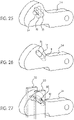
- the at least one slot 18 may extend at various angles (or orientations) with respect to the body of the first pivot member 24 and/or the second pivot member 30. In one preferred and non-limiting embodiment or aspect, and as shown in Fig. 26 , the at least one slot 18 may extend to various lengths.
- the pins 60, 66, 68, 70 may have or exhibit various shapes or cross sections, such as circular, triangular, square, and the like.
- the at least one pin 68 has a square shape, which changes the manner in which the at least one pin 68 moves along and within the at least one slot 18.
- the at least one pin 60 may also include a different shape, such as a shape that assists in the attachment or operation of the at least one biasing member 40.
Landscapes
- Health & Medical Sciences (AREA)
- General Health & Medical Sciences (AREA)
- Business, Economics & Management (AREA)
- Emergency Management (AREA)
- Engineering & Computer Science (AREA)
- General Engineering & Computer Science (AREA)
- Mechanical Engineering (AREA)
- Emergency Lowering Means (AREA)
- Installation Of Indoor Wiring (AREA)
- Electric Cable Arrangement Between Relatively Moving Parts (AREA)
Claims (15)
- Fallschutzvorrichtung (10) zur Verwendung mit einem sich allgemein vertikal erstreckenden Kabel (C), umfassend:wenigstens ein erstes seitliches Element (20) mit einem Kanal (14), der dazu ausgestaltet ist, das Kabel (C) aufzunehmen und zu halten;wenigstens ein zweites seitliches Element (22), das von dem wenigstens einen ersten seitlichen Element (20) beabstandet ist;wenigstens ein erstes Schwenkelement (24), das schwenkbar zwischen einem ersten Ende (26) des wenigstens einen ersten seitlichen Elements (20) und einem ersten Ende (28) des wenigstens einen zweiten seitlichen Elements (22) befestigt ist;wenigstens ein zweites Schwenkelement (30), das schwenkbar zwischen einem zweiten Ende (32) des wenigstens einen ersten seitlichen Elements (20) und einem zweiten Ende (34) des wenigstens einen zweiten seitlichen Elements (22) befestigt ist; undeine Befestigungselementöffnung (16), die sich durch wenigstens einen Abschnitt von wenigstens einem der folgenden hindurch erstreckt: dem wenigstens einen zweiten seitlichen Element (22), dem wenigstens einen ersten Schwenkelement (24), dem wenigstens einen zweiten Schwenkelement (30) oder einer Kombination derselben, wobei die Befestigungselementöffnung (16) dazu ausgestaltet ist, die Befestigung eines Befestigungselements an der Fallschutzvorrichtung (10) zu ermöglichen;wobei wenn die Fallschutzvorrichtung (10) in einer allgemein nach unten gerichteten Richtung bewegt oder gedrückt wird, und an einem festgelegten Punkt wenigstens ein Abschnitt eines ersten Endes (36) des wenigstens einen ersten Schwenkelements (24) und/oder eines ersten Endes (38) des wenigstens einen zweiten Schwenkelements (30) mit dem Kabel (C) in Kontakt kommt und die Bewegung der Fallschutzvorrichtung (10) bremst oder stoppt;dadurch gekennzeichnet, dasswenigstens ein Schlitz (18) sich durch wenigstens einen Abschnitt des ersten Endes (36) des wenigstens einen ersten Schwenkelements (24) und/oder des ersten Endes (38) des wenigstens einen zweiten Schwenkelements (30) hindurch erstreckt und wenigstens ein Stift (68) sich durch den wenigstens einen Schlitz (18) hindurch erstreckt und dazu ausgestaltet ist, diesen entlang zu gleiten, sodass, wenn das wenigstens eine zweite seitliche Element (22) in Bezug auf das wenigstens eine erste seitliche Element (20) in eine allgemein nach oben gerichtete Richtung gedrückt oder bewegt wird, und an einem festgelegten Punkt wenigstens ein Abschnitt des ersten Endes (36) des wenigstens einen ersten Schwenkelements (24) und/oder des ersten Endes (38) des wenigstens einen zweiten Schwenkelements (30) mit dem Kabel (C) in Kontakt kommt und die Fallschutzvorrichtung (10) bremst.
- Fallschutzvorrichtung (10) nach Anspruch 1, die ferner wenigstens ein Vorspannelement (40) umfasst, das dazu ausgestaltet ist, das wenigstens eine zweite seitliche Element (22) in eine Richtung vorzuspannen oder zu drücken, wobei insbesondere das wenigstens eine Vorspannelement (40) eine Feder ist.
- Fallschutzvorrichtung (10) nach Anspruch 1, wobei das wenigstens eine erste seitliche Element (20) einen im Wesentlichen U-förmigen Querschnitt umfasst, wobei ein Basisbereich (42) der U-Form den Kanal (14) definiert und ein oberer Bereich (44) der U-Form dazu ausgestaltet ist, wenigstens einen Abschnitt des ersten Endes (36) des wenigstens einen ersten Schwenkelements (24) und wenigstens einen Abschnitt des ersten Endes (38) des wenigstens einen zweiten Schwenkelements (30) zwischen sich aufzunehmen, wobei insbesondere ein Formschlitz (46) sich in dem Basisbereich (42) der U-Form befindet, sodass die Fallschutzvorrichtung (10) abnehmbar mit dem Kabel (C) verbindbar ist, indem zuerst der Formschlitz (46) über das Kabel (C) bewegt wird und die Fallschutzvorrichtung (10) verdreht wird, damit das Kabel (C) in dem Kanal (14) zu liegen kommt.
- Fallschutzvorrichtung (10) nach Anspruch 1, wobei die Befestigungselementöffnung (16) einen Schlitz (54) definiert, der sich von einem Umfang der Befestigungselementöffnung (16) aus erstreckt, wobei ein gleitfähiges Element (56) wenigstens teilweise in dem Schlitz (54) befindlich und entlang der Befestigungselementöffnung (16) und des Schlitzes (54) gleitfähig ist.
- Fallschutzvorrichtung (10) nach Anspruch 1, wobei das wenigstens eine erste seitliche Element (20) einen im Wesentlichen U-förmigen Querschnitt umfasst, wobei ein oberer Bereich (44) der U-Form durch eine erste Wand (62) und eine zweite Wand (64) definiert ist und dazu ausgestaltet ist, wenigstens einen Abschnitt des ersten Endes (36) des wenigstens einen ersten Schwenkelements (24) und wenigstens einen Abschnitt des ersten Endes (38) des wenigstens einen zweiten Schwenkelements (30) zwischen sich aufzunehmen, wobei wenigstens ein Stift (60) direkt oder indirekt wenigstens eines der Mehrzahl zweiter Schwenkelemente (30) zwischen der ersten Wand (62) und der zweiten Wand (64) einbindet.
- Fallschutzvorrichtung (10) nach Anspruch 2, wobei:
das wenigstens eine Vorspannelement (40) direkt oder indirekt mit wenigstens einem Abschnitt von wenigstens einem der Mehrzahl zweiter Schwenkelemente (30) in Kontakt steht. - Fallschutzvorrichtung (10) nach Anspruch 1, die ferner wenigstens einen Stift (66) umfasst, der direkt oder indirekt ein zweites Ende (72) von wenigstens einem der Mehrzahl zweiter Schwenkelemente (30) mit dem wenigstens einen zweiten seitlichen Element (22) verbindet.
- Fallschutzvorrichtung (10) nach Anspruch 1, wobei das wenigstens eine erste Schwenkelement (24) so geformt ist, dass ein Rand des ersten Endes (36) des wenigstens einen ersten Schwenkelements (24) mit dem Kabel (C) in Kontakt kommt, um die Fallschutzvorrichtung (10) zu bremsen.
- Fallschutzvorrichtung (10) nach Anspruch 1, die ferner eine Mehrzahl erster Schwenkelemente (24) umfasst, wobei wenigstens eines der Mehrzahl erster Schwenkelemente (24) dazu ausgestaltet ist, mit dem Kabel (C) in Kontakt zu kommen, um die Fallschutzvorrichtung (10) zu bremsen.
- Fallschutzvorrichtung (10) nach Anspruch 9, wobei der wenigstens eine Stift (68) direkt oder indirekt das erste Ende (36) von wenigstens einem der Mehrzahl erster Schwenkelemente (24) schwenkbar mit dem wenigstens einen ersten seitlichen Element (20) verbindet.
- Fallschutzvorrichtung (10) nach Anspruch 10, wobei wenigstens eines der Folgenden gegeben ist:der wenigstens eine Schlitz (18) erstreckt sich durch das erste Ende (36) der Mehrzahl erster Schwenkelemente (24) hindurch, unddas wenigstens eine erste seitliche Element (20) umfasst einen im Wesentlichen U-förmigen Querschnitt, wobei ein oberer Bereich der U-Form durch eine erste Wand (62) und eine zweite Wand (64) definiert ist und dazu ausgestaltet ist, wenigstens einen Abschnitt des ersten Endes (36) des wenigstens einen ersten Schwenkelements (24) und wenigstens einen Abschnitt des ersten Endes (38) des wenigstens einen zweiten Schwenkelements (30) zwischen sich aufzunehmen, wobei der wenigstens eine Stift (68) direkt oder indirekt wenigstens eines der Mehrzahl erster Schwenkelemente (24) zwischen der ersten Wand (62) und der zweiten Wand (64) einbindet.
- Fallschutzvorrichtung (10) nach Anspruch 1, wobei wenigstens ein Abschnitt des wenigstens einen ersten Schwenkelements (24) und/oder des wenigstens einen zweiten Schwenkelements (30) zwischen zwei zweiten seitlichen Elementen (22) eingebunden ist und/oder wenigstens eines der folgenden umfasst:
Vorsprünge, Einkerbungen, Rippen, Schlitze, Nuten, eine Beschichtung, ein Reibungsmaterial, eine Rändelung oder eine beliebige Kombination derselben. - Fallschutzvorrichtung (10) nach Anspruch 1, wobei der wenigstens eine Schlitz (18) sich durch wenigstens einen Abschnitt des ersten Endes (36) des wenigstens einen ersten Schwenkelements (24) hindurch erstreckt.
- Fallschutzvorrichtung (10) nach Anspruch 1, wobei der wenigstens eine Schlitz (18) wenigstens eines der folgenden aufweist: Form, Größe, Ausrichtung oder eine beliebige Kombination davon, um die Bewegung oder das Drücken wenigstens eines Abschnitts des ersten Endes (36) des wenigstens einen ersten Schwenkelements (24) und/oder des ersten Endes (38) des wenigstens einen zweiten Schwenkelements (30) in Kontakt mit dem Kabel (C) zum Bremsen oder Stoppen der Bewegung der Fallschutzvorrichtung (10) zu ermöglichen.
- Fallschutzvorrichtung (10) nach Anspruch 1, wobei der wenigstens eine Stift (60, 66, 68, 70) wenigstens einen der folgenden Querschnitte aufweist: kreisförmig, dreieckig, quadratisch oder eine beliebige Kombination davon.
Applications Claiming Priority (2)
| Application Number | Priority Date | Filing Date | Title |
|---|---|---|---|
| US14/919,501 US9750959B2 (en) | 2015-10-21 | 2015-10-21 | Cable grab device |
| PCT/US2016/057862 WO2017070314A1 (en) | 2015-10-21 | 2016-10-20 | Cable grab device |
Publications (2)
| Publication Number | Publication Date |
|---|---|
| EP3365070A1 EP3365070A1 (de) | 2018-08-29 |
| EP3365070B1 true EP3365070B1 (de) | 2022-10-26 |
Family
ID=57227137
Family Applications (1)
| Application Number | Title | Priority Date | Filing Date |
|---|---|---|---|
| EP16790829.2A Active EP3365070B1 (de) | 2015-10-21 | 2016-10-20 | Kabelgreifvorrichtung |
Country Status (5)
| Country | Link |
|---|---|
| US (1) | US9750959B2 (de) |
| EP (1) | EP3365070B1 (de) |
| CN (1) | CN108367180B (de) |
| CA (1) | CA3002812C (de) |
| WO (1) | WO2017070314A1 (de) |
Families Citing this family (12)
| Publication number | Priority date | Publication date | Assignee | Title |
|---|---|---|---|---|
| USD850246S1 (en) * | 2016-01-06 | 2019-06-04 | Nagaki Seiki Co., Ltd. | Wire gripper |
| CN109069890B (zh) | 2016-03-23 | 2021-05-07 | 霍尼韦尔国际公司 | 用于攀爬保护系统的梭子 |
| US11052270B2 (en) | 2017-07-24 | 2021-07-06 | Sayfa R&D Pty Ltd | Vertical fall arrest safety device |
| CA3035263C (en) * | 2017-07-24 | 2019-07-30 | Sayfa R&D Pty Ltd | A modular ladder system |
| US10669117B2 (en) * | 2017-11-21 | 2020-06-02 | Kenneth Hunt | Portable rope guiding apparatus |
| CN111491697B (zh) * | 2017-12-19 | 2021-05-04 | 3M创新有限公司 | 用于坠落防护安全系统的顶部托架 |
| CA189025S (en) | 2019-01-30 | 2021-12-13 | Sayfa R&D Pty Ltd | Vertical fall arrest safety device |
| DE202020102347U1 (de) * | 2019-05-01 | 2020-07-24 | Ti-An Chih | Ein sofortiges und präzises Verriegeln und Lösen eines Seils ermöglichende Vorrichtung |
| US12068716B2 (en) * | 2019-05-21 | 2024-08-20 | Nclave Renewable, S.L. | Anti-torsion device for a solar tracker with a rotation axis, and solar tracker comprising said anti-torsion device |
| EP4159288A1 (de) | 2021-09-30 | 2023-04-05 | Fam Service S.r.l. | Absturzsicherung und verfahren zum sicheren zugriff auf eine erhabene oberfläche mittels dieser vorrichtung |
| US20230405365A1 (en) * | 2022-06-17 | 2023-12-21 | Werner Co. | Cable grab |
| US12128258B1 (en) * | 2023-04-25 | 2024-10-29 | Sherrill, Inc. | Descent control device |
Family Cites Families (28)
| Publication number | Priority date | Publication date | Assignee | Title |
|---|---|---|---|---|
| US3386530A (en) * | 1966-12-07 | 1968-06-04 | Meyer Machine Inc | Safety clamp device |
| US3492702A (en) * | 1968-04-29 | 1970-02-03 | Lawrence R Stafford | Line grip device |
| US3811155A (en) * | 1972-06-21 | 1974-05-21 | L Stafford | Rope grab assembly |
| US3852943A (en) * | 1973-08-27 | 1974-12-10 | Meyer Ind Inc | Portable safety clamp |
| US4034828A (en) * | 1975-04-14 | 1977-07-12 | Rose Manufacturing Company | Shock absorbing cable connector |
| US4254941A (en) * | 1979-06-06 | 1981-03-10 | Groupements D'interets Economiques Europe-Levage-Manutention (Elma) | Automatic anti-fall device for manual or motorized lifting systems |
| US4542884A (en) * | 1983-06-06 | 1985-09-24 | Dodge Jr Cleveland E | Removable double action rope grip |
| DE3510602A1 (de) | 1985-03-23 | 1986-09-25 | Mittelmann & Co Armaturenwerk, 5603 Wülfrath | Seilsicherungsklemme |
| GB8627320D0 (en) * | 1986-11-14 | 1986-12-17 | Latchways Ltd | Lockable load-transfer |
| US5156240A (en) * | 1991-05-31 | 1992-10-20 | Meyer Ostrobrod | Rope grab |
| US5133111A (en) * | 1991-09-26 | 1992-07-28 | Brown Michael A | Cam cleat |
| FR2686962B3 (fr) | 1992-02-05 | 1994-01-07 | Komet | Perfectionnements aux dispositifs de securite mobiles le long d'un cable. |
| CN2152573Y (zh) * | 1993-02-27 | 1994-01-12 | 徐汉中 | 微型防坠器 |
| ES2116153B1 (es) * | 1994-05-30 | 1999-05-16 | Ganchos De Seguridad S L | Sistema de seguridad para aparatos elevadores. |
| FR2736273A1 (fr) * | 1995-07-03 | 1997-01-10 | Sk Sarl | Antichute mobile pour support d'assurage |
| FR2757774B1 (fr) * | 1996-12-27 | 1999-03-19 | Komet | Appareil antichute sur cable vertical |
| US5855251A (en) * | 1997-01-22 | 1999-01-05 | Deuer; Joseph F. | Security device for use with a safety line |
| US20020014370A1 (en) * | 2000-04-17 | 2002-02-07 | Casebolt Scott C. | Fall arrest methods and apparatus with u-joint connector |
| FR2815876B1 (fr) * | 2000-11-02 | 2003-01-17 | Protecta Internat Sa | Procede pour la securite des personnes et dispositif |
| WO2002057176A1 (fr) * | 2001-01-18 | 2002-07-25 | Plumettaz Sa | Dispositifs de freinage d'urgence et d'amortissement de chocs pour un ascenseur ou charges suspendu |
| FR2842113B1 (fr) * | 2002-07-12 | 2004-09-24 | Zedel | Dispositif antichute suiveur pour corde fixe |
| EP1680192B8 (de) * | 2003-10-21 | 2012-08-08 | Uniline Safety Systems Limited | Vorrichtung zum aufhalten eines falls und system mit dieser vorrichtung |
| FR2898506B1 (fr) * | 2006-03-15 | 2008-05-30 | Zedel Soc Par Actions Simplifi | Appareil multifonctionnel d'assurage pour corde |
| FR2938771B1 (fr) * | 2008-11-27 | 2010-12-31 | Zedel | Dispositif bloqueur a came pour l'assurage sur corde fixe |
| USD633783S1 (en) * | 2009-06-30 | 2011-03-08 | Nagaki Seiki Co., Ltd | Wire grip |
| USD633784S1 (en) * | 2009-12-28 | 2011-03-08 | Nagaki Seiki Co., Ltd. | Wire grip |
| FR2970183B1 (fr) * | 2011-01-11 | 2014-11-21 | Tractel Sas | Dispositif d'arret automatique de chute pour travailleur en hauteur. |
| US9168402B2 (en) * | 2012-07-18 | 2015-10-27 | D B Industries, Llc | Rope grab |
-
2015
- 2015-10-21 US US14/919,501 patent/US9750959B2/en active Active
-
2016
- 2016-10-20 EP EP16790829.2A patent/EP3365070B1/de active Active
- 2016-10-20 CA CA3002812A patent/CA3002812C/en active Active
- 2016-10-20 WO PCT/US2016/057862 patent/WO2017070314A1/en not_active Ceased
- 2016-10-20 CN CN201680072907.6A patent/CN108367180B/zh active Active
Also Published As
| Publication number | Publication date |
|---|---|
| US20170113072A1 (en) | 2017-04-27 |
| US9750959B2 (en) | 2017-09-05 |
| WO2017070314A1 (en) | 2017-04-27 |
| CA3002812C (en) | 2023-08-22 |
| CA3002812A1 (en) | 2017-04-27 |
| EP3365070A1 (de) | 2018-08-29 |
| CN108367180A (zh) | 2018-08-03 |
| CN108367180B (zh) | 2020-09-22 |
Similar Documents
| Publication | Publication Date | Title |
|---|---|---|
| US9750959B2 (en) | Cable grab device | |
| CA2877993C (en) | Rope grab | |
| US9132297B2 (en) | Rope grab | |
| US20210207646A1 (en) | Carabiner Divider and Fall Arrest System | |
| US20110315480A1 (en) | Ascender/descender appliance for climbing and decending on a rope | |
| US20140311834A1 (en) | Fall arrest device | |
| US20210196995A1 (en) | Suspension cable wall anchoring device | |
| EP2525878B1 (de) | Sicherheitssystem mit zwei jeweils an einem selbstsicherungselement aufgehängten karabinerhaken für kletterzwecke, abenteuerparks, arbeiten an ingenieurbauten oder allgemeine arbeiten, die sicherheitsseile erfordern | |
| US20190277088A1 (en) | Pass-Through Cable Grab System | |
| CN105615069A (zh) | 防坠落手套 | |
| US20160016042A1 (en) | Ascender for ascending on a rope | |
| AU2010249942B2 (en) | Method, apparatus and arrangement for a lifeline system | |
| US9364695B2 (en) | Trolley comprising a fall arrest actuator | |
| KR101283056B1 (ko) | 연속 빌레이의 셔틀 | |
| GB2590609A (en) | Remote clipping device | |
| JP2016093486A (ja) | 傾斜面用ランヤードのグリップ及び安全対策装備並びに傾斜面作業における二重安全対策方法 | |
| DK2288417T3 (en) | Co-capture device | |
| US12168149B2 (en) | Fall arrester | |
| GB2522721A (en) | Fall arrest device | |
| US5058706A (en) | Safety controller for high-building escapee | |
| KR200471830Y1 (ko) | 로프고정용 안전 연결고리 | |
| US4116305A (en) | Mechanical robe grab |
Legal Events
| Date | Code | Title | Description |
|---|---|---|---|
| STAA | Information on the status of an ep patent application or granted ep patent |
Free format text: STATUS: UNKNOWN |
|
| STAA | Information on the status of an ep patent application or granted ep patent |
Free format text: STATUS: THE INTERNATIONAL PUBLICATION HAS BEEN MADE |
|
| PUAI | Public reference made under article 153(3) epc to a published international application that has entered the european phase |
Free format text: ORIGINAL CODE: 0009012 |
|
| STAA | Information on the status of an ep patent application or granted ep patent |
Free format text: STATUS: REQUEST FOR EXAMINATION WAS MADE |
|
| 17P | Request for examination filed |
Effective date: 20180508 |
|
| AK | Designated contracting states |
Kind code of ref document: A1 Designated state(s): AL AT BE BG CH CY CZ DE DK EE ES FI FR GB GR HR HU IE IS IT LI LT LU LV MC MK MT NL NO PL PT RO RS SE SI SK SM TR |
|
| AX | Request for extension of the european patent |
Extension state: BA ME |
|
| DAV | Request for validation of the european patent (deleted) | ||
| DAX | Request for extension of the european patent (deleted) | ||
| STAA | Information on the status of an ep patent application or granted ep patent |
Free format text: STATUS: EXAMINATION IS IN PROGRESS |
|
| 17Q | First examination report despatched |
Effective date: 20200911 |
|
| GRAP | Despatch of communication of intention to grant a patent |
Free format text: ORIGINAL CODE: EPIDOSNIGR1 |
|
| STAA | Information on the status of an ep patent application or granted ep patent |
Free format text: STATUS: GRANT OF PATENT IS INTENDED |
|
| INTG | Intention to grant announced |
Effective date: 20220620 |
|
| GRAS | Grant fee paid |
Free format text: ORIGINAL CODE: EPIDOSNIGR3 |
|
| GRAA | (expected) grant |
Free format text: ORIGINAL CODE: 0009210 |
|
| STAA | Information on the status of an ep patent application or granted ep patent |
Free format text: STATUS: THE PATENT HAS BEEN GRANTED |
|
| AK | Designated contracting states |
Kind code of ref document: B1 Designated state(s): AL AT BE BG CH CY CZ DE DK EE ES FI FR GB GR HR HU IE IS IT LI LT LU LV MC MK MT NL NO PL PT RO RS SE SI SK SM TR |
|
| REG | Reference to a national code |
Ref country code: GB Ref legal event code: FG4D |
|
| REG | Reference to a national code |
Ref country code: CH Ref legal event code: EP |
|
| REG | Reference to a national code |
Ref country code: AT Ref legal event code: REF Ref document number: 1526637 Country of ref document: AT Kind code of ref document: T Effective date: 20221115 |
|
| REG | Reference to a national code |
Ref country code: DE Ref legal event code: R096 Ref document number: 602016075903 Country of ref document: DE |
|
| REG | Reference to a national code |
Ref country code: IE Ref legal event code: FG4D |
|
| REG | Reference to a national code |
Ref country code: LT Ref legal event code: MG9D |
|
| REG | Reference to a national code |
Ref country code: NL Ref legal event code: MP Effective date: 20221026 |
|
| REG | Reference to a national code |
Ref country code: AT Ref legal event code: MK05 Ref document number: 1526637 Country of ref document: AT Kind code of ref document: T Effective date: 20221026 |
|
| PG25 | Lapsed in a contracting state [announced via postgrant information from national office to epo] |
Ref country code: NL Free format text: LAPSE BECAUSE OF FAILURE TO SUBMIT A TRANSLATION OF THE DESCRIPTION OR TO PAY THE FEE WITHIN THE PRESCRIBED TIME-LIMIT Effective date: 20221026 |
|
| PG25 | Lapsed in a contracting state [announced via postgrant information from national office to epo] |
Ref country code: SE Free format text: LAPSE BECAUSE OF FAILURE TO SUBMIT A TRANSLATION OF THE DESCRIPTION OR TO PAY THE FEE WITHIN THE PRESCRIBED TIME-LIMIT Effective date: 20221026 Ref country code: PT Free format text: LAPSE BECAUSE OF FAILURE TO SUBMIT A TRANSLATION OF THE DESCRIPTION OR TO PAY THE FEE WITHIN THE PRESCRIBED TIME-LIMIT Effective date: 20230227 Ref country code: NO Free format text: LAPSE BECAUSE OF FAILURE TO SUBMIT A TRANSLATION OF THE DESCRIPTION OR TO PAY THE FEE WITHIN THE PRESCRIBED TIME-LIMIT Effective date: 20230126 Ref country code: LT Free format text: LAPSE BECAUSE OF FAILURE TO SUBMIT A TRANSLATION OF THE DESCRIPTION OR TO PAY THE FEE WITHIN THE PRESCRIBED TIME-LIMIT Effective date: 20221026 Ref country code: FI Free format text: LAPSE BECAUSE OF FAILURE TO SUBMIT A TRANSLATION OF THE DESCRIPTION OR TO PAY THE FEE WITHIN THE PRESCRIBED TIME-LIMIT Effective date: 20221026 Ref country code: ES Free format text: LAPSE BECAUSE OF FAILURE TO SUBMIT A TRANSLATION OF THE DESCRIPTION OR TO PAY THE FEE WITHIN THE PRESCRIBED TIME-LIMIT Effective date: 20221026 Ref country code: AT Free format text: LAPSE BECAUSE OF FAILURE TO SUBMIT A TRANSLATION OF THE DESCRIPTION OR TO PAY THE FEE WITHIN THE PRESCRIBED TIME-LIMIT Effective date: 20221026 |
|
| PG25 | Lapsed in a contracting state [announced via postgrant information from national office to epo] |
Ref country code: RS Free format text: LAPSE BECAUSE OF FAILURE TO SUBMIT A TRANSLATION OF THE DESCRIPTION OR TO PAY THE FEE WITHIN THE PRESCRIBED TIME-LIMIT Effective date: 20221026 Ref country code: PL Free format text: LAPSE BECAUSE OF FAILURE TO SUBMIT A TRANSLATION OF THE DESCRIPTION OR TO PAY THE FEE WITHIN THE PRESCRIBED TIME-LIMIT Effective date: 20221026 Ref country code: LV Free format text: LAPSE BECAUSE OF FAILURE TO SUBMIT A TRANSLATION OF THE DESCRIPTION OR TO PAY THE FEE WITHIN THE PRESCRIBED TIME-LIMIT Effective date: 20221026 Ref country code: IS Free format text: LAPSE BECAUSE OF FAILURE TO SUBMIT A TRANSLATION OF THE DESCRIPTION OR TO PAY THE FEE WITHIN THE PRESCRIBED TIME-LIMIT Effective date: 20230226 Ref country code: HR Free format text: LAPSE BECAUSE OF FAILURE TO SUBMIT A TRANSLATION OF THE DESCRIPTION OR TO PAY THE FEE WITHIN THE PRESCRIBED TIME-LIMIT Effective date: 20221026 Ref country code: GR Free format text: LAPSE BECAUSE OF FAILURE TO SUBMIT A TRANSLATION OF THE DESCRIPTION OR TO PAY THE FEE WITHIN THE PRESCRIBED TIME-LIMIT Effective date: 20230127 |
|
| REG | Reference to a national code |
Ref country code: DE Ref legal event code: R097 Ref document number: 602016075903 Country of ref document: DE |
|
| PG25 | Lapsed in a contracting state [announced via postgrant information from national office to epo] |
Ref country code: SM Free format text: LAPSE BECAUSE OF FAILURE TO SUBMIT A TRANSLATION OF THE DESCRIPTION OR TO PAY THE FEE WITHIN THE PRESCRIBED TIME-LIMIT Effective date: 20221026 Ref country code: RO Free format text: LAPSE BECAUSE OF FAILURE TO SUBMIT A TRANSLATION OF THE DESCRIPTION OR TO PAY THE FEE WITHIN THE PRESCRIBED TIME-LIMIT Effective date: 20221026 Ref country code: EE Free format text: LAPSE BECAUSE OF FAILURE TO SUBMIT A TRANSLATION OF THE DESCRIPTION OR TO PAY THE FEE WITHIN THE PRESCRIBED TIME-LIMIT Effective date: 20221026 Ref country code: DK Free format text: LAPSE BECAUSE OF FAILURE TO SUBMIT A TRANSLATION OF THE DESCRIPTION OR TO PAY THE FEE WITHIN THE PRESCRIBED TIME-LIMIT Effective date: 20221026 Ref country code: CZ Free format text: LAPSE BECAUSE OF FAILURE TO SUBMIT A TRANSLATION OF THE DESCRIPTION OR TO PAY THE FEE WITHIN THE PRESCRIBED TIME-LIMIT Effective date: 20221026 |
|
| P01 | Opt-out of the competence of the unified patent court (upc) registered |
Effective date: 20230626 |
|
| PG25 | Lapsed in a contracting state [announced via postgrant information from national office to epo] |
Ref country code: SK Free format text: LAPSE BECAUSE OF FAILURE TO SUBMIT A TRANSLATION OF THE DESCRIPTION OR TO PAY THE FEE WITHIN THE PRESCRIBED TIME-LIMIT Effective date: 20221026 Ref country code: AL Free format text: LAPSE BECAUSE OF FAILURE TO SUBMIT A TRANSLATION OF THE DESCRIPTION OR TO PAY THE FEE WITHIN THE PRESCRIBED TIME-LIMIT Effective date: 20221026 |
|
| PLBE | No opposition filed within time limit |
Free format text: ORIGINAL CODE: 0009261 |
|
| STAA | Information on the status of an ep patent application or granted ep patent |
Free format text: STATUS: NO OPPOSITION FILED WITHIN TIME LIMIT |
|
| 26N | No opposition filed |
Effective date: 20230727 |
|
| PG25 | Lapsed in a contracting state [announced via postgrant information from national office to epo] |
Ref country code: SI Free format text: LAPSE BECAUSE OF FAILURE TO SUBMIT A TRANSLATION OF THE DESCRIPTION OR TO PAY THE FEE WITHIN THE PRESCRIBED TIME-LIMIT Effective date: 20221026 |
|
| PG25 | Lapsed in a contracting state [announced via postgrant information from national office to epo] |
Ref country code: IT Free format text: LAPSE BECAUSE OF FAILURE TO SUBMIT A TRANSLATION OF THE DESCRIPTION OR TO PAY THE FEE WITHIN THE PRESCRIBED TIME-LIMIT Effective date: 20221026 Ref country code: MC Free format text: LAPSE BECAUSE OF FAILURE TO SUBMIT A TRANSLATION OF THE DESCRIPTION OR TO PAY THE FEE WITHIN THE PRESCRIBED TIME-LIMIT Effective date: 20221026 |
|
| REG | Reference to a national code |
Ref country code: CH Ref legal event code: PL |
|
| REG | Reference to a national code |
Ref country code: BE Ref legal event code: MM Effective date: 20231031 |
|
| PG25 | Lapsed in a contracting state [announced via postgrant information from national office to epo] |
Ref country code: LU Free format text: LAPSE BECAUSE OF NON-PAYMENT OF DUE FEES Effective date: 20231020 |
|
| PG25 | Lapsed in a contracting state [announced via postgrant information from national office to epo] |
Ref country code: LU Free format text: LAPSE BECAUSE OF NON-PAYMENT OF DUE FEES Effective date: 20231020 |
|
| PG25 | Lapsed in a contracting state [announced via postgrant information from national office to epo] |
Ref country code: CH Free format text: LAPSE BECAUSE OF NON-PAYMENT OF DUE FEES Effective date: 20231031 |
|
| PG25 | Lapsed in a contracting state [announced via postgrant information from national office to epo] |
Ref country code: CH Free format text: LAPSE BECAUSE OF NON-PAYMENT OF DUE FEES Effective date: 20231031 |
|
| PG25 | Lapsed in a contracting state [announced via postgrant information from national office to epo] |
Ref country code: BE Free format text: LAPSE BECAUSE OF NON-PAYMENT OF DUE FEES Effective date: 20231031 |
|
| PG25 | Lapsed in a contracting state [announced via postgrant information from national office to epo] |
Ref country code: IE Free format text: LAPSE BECAUSE OF NON-PAYMENT OF DUE FEES Effective date: 20231020 |
|
| PG25 | Lapsed in a contracting state [announced via postgrant information from national office to epo] |
Ref country code: IE Free format text: LAPSE BECAUSE OF NON-PAYMENT OF DUE FEES Effective date: 20231020 |
|
| PG25 | Lapsed in a contracting state [announced via postgrant information from national office to epo] |
Ref country code: BG Free format text: LAPSE BECAUSE OF FAILURE TO SUBMIT A TRANSLATION OF THE DESCRIPTION OR TO PAY THE FEE WITHIN THE PRESCRIBED TIME-LIMIT Effective date: 20221026 |
|
| PG25 | Lapsed in a contracting state [announced via postgrant information from national office to epo] |
Ref country code: BG Free format text: LAPSE BECAUSE OF FAILURE TO SUBMIT A TRANSLATION OF THE DESCRIPTION OR TO PAY THE FEE WITHIN THE PRESCRIBED TIME-LIMIT Effective date: 20221026 |
|
| PG25 | Lapsed in a contracting state [announced via postgrant information from national office to epo] |
Ref country code: CY Free format text: LAPSE BECAUSE OF FAILURE TO SUBMIT A TRANSLATION OF THE DESCRIPTION OR TO PAY THE FEE WITHIN THE PRESCRIBED TIME-LIMIT; INVALID AB INITIO Effective date: 20161020 |
|
| PG25 | Lapsed in a contracting state [announced via postgrant information from national office to epo] |
Ref country code: HU Free format text: LAPSE BECAUSE OF FAILURE TO SUBMIT A TRANSLATION OF THE DESCRIPTION OR TO PAY THE FEE WITHIN THE PRESCRIBED TIME-LIMIT; INVALID AB INITIO Effective date: 20161020 |
|
| PGFP | Annual fee paid to national office [announced via postgrant information from national office to epo] |
Ref country code: GB Payment date: 20250904 Year of fee payment: 10 |
|
| PGFP | Annual fee paid to national office [announced via postgrant information from national office to epo] |
Ref country code: FR Payment date: 20250908 Year of fee payment: 10 |
|
| PG25 | Lapsed in a contracting state [announced via postgrant information from national office to epo] |
Ref country code: TR Free format text: LAPSE BECAUSE OF FAILURE TO SUBMIT A TRANSLATION OF THE DESCRIPTION OR TO PAY THE FEE WITHIN THE PRESCRIBED TIME-LIMIT Effective date: 20221026 |
|
| PGFP | Annual fee paid to national office [announced via postgrant information from national office to epo] |
Ref country code: DE Payment date: 20250902 Year of fee payment: 10 |