EP3364518B1 - System und verfahren zum erkennen und reparieren von netzwerkverbindungsproblemen - Google Patents
System und verfahren zum erkennen und reparieren von netzwerkverbindungsproblemen Download PDFInfo
- Publication number
- EP3364518B1 EP3364518B1 EP18157217.3A EP18157217A EP3364518B1 EP 3364518 B1 EP3364518 B1 EP 3364518B1 EP 18157217 A EP18157217 A EP 18157217A EP 3364518 B1 EP3364518 B1 EP 3364518B1
- Authority
- EP
- European Patent Office
- Prior art keywords
- power
- network
- controller
- output
- domain name
- Prior art date
- Legal status (The legal status is an assumption and is not a legal conclusion. Google has not performed a legal analysis and makes no representation as to the accuracy of the status listed.)
- Active
Links
Images


Classifications
-
- H—ELECTRICITY
- H04—ELECTRIC COMMUNICATION TECHNIQUE
- H04L—TRANSMISSION OF DIGITAL INFORMATION, e.g. TELEGRAPHIC COMMUNICATION
- H04L43/00—Arrangements for monitoring or testing data switching networks
- H04L43/08—Monitoring or testing based on specific metrics, e.g. QoS, energy consumption or environmental parameters
- H04L43/0805—Monitoring or testing based on specific metrics, e.g. QoS, energy consumption or environmental parameters by checking availability
- H04L43/0817—Monitoring or testing based on specific metrics, e.g. QoS, energy consumption or environmental parameters by checking availability by checking functioning
-
- H—ELECTRICITY
- H04—ELECTRIC COMMUNICATION TECHNIQUE
- H04L—TRANSMISSION OF DIGITAL INFORMATION, e.g. TELEGRAPHIC COMMUNICATION
- H04L43/00—Arrangements for monitoring or testing data switching networks
- H04L43/08—Monitoring or testing based on specific metrics, e.g. QoS, energy consumption or environmental parameters
- H04L43/0805—Monitoring or testing based on specific metrics, e.g. QoS, energy consumption or environmental parameters by checking availability
- H04L43/0811—Monitoring or testing based on specific metrics, e.g. QoS, energy consumption or environmental parameters by checking availability by checking connectivity
-
- H—ELECTRICITY
- H02—GENERATION; CONVERSION OR DISTRIBUTION OF ELECTRIC POWER
- H02J—ELECTRIC POWER NETWORKS; CIRCUIT ARRANGEMENTS OR SYSTEMS FOR SUPPLYING OR DISTRIBUTING ELECTRIC POWER; SYSTEMS FOR STORING ELECTRIC ENERGY
- H02J13/00—Circuit arrangements for providing remote monitoring or remote control of equipment in a power distribution network
- H02J13/18—Circuit arrangements for providing remote monitoring or remote control of equipment in a power distribution network characterised by the remotely-controlled equipment, e.g. converters or transformers
- H02J13/38—Circuit arrangements for providing remote monitoring or remote control of equipment in a power distribution network characterised by the remotely-controlled equipment, e.g. converters or transformers the equipment being power outlets
-
- G—PHYSICS
- G06—COMPUTING OR CALCULATING; COUNTING
- G06F—ELECTRIC DIGITAL DATA PROCESSING
- G06F1/00—Details not covered by groups G06F3/00 - G06F13/00 and G06F21/00
- G06F1/26—Power supply means, e.g. regulation thereof
-
- G—PHYSICS
- G06—COMPUTING OR CALCULATING; COUNTING
- G06F—ELECTRIC DIGITAL DATA PROCESSING
- G06F1/00—Details not covered by groups G06F3/00 - G06F13/00 and G06F21/00
- G06F1/26—Power supply means, e.g. regulation thereof
- G06F1/266—Arrangements to supply power to external peripherals either directly from the computer or under computer control, e.g. supply of power through the communication port, computer controlled power-strips
-
- H—ELECTRICITY
- H02—GENERATION; CONVERSION OR DISTRIBUTION OF ELECTRIC POWER
- H02J—ELECTRIC POWER NETWORKS; CIRCUIT ARRANGEMENTS OR SYSTEMS FOR SUPPLYING OR DISTRIBUTING ELECTRIC POWER; SYSTEMS FOR STORING ELECTRIC ENERGY
- H02J13/00—Circuit arrangements for providing remote monitoring or remote control of equipment in a power distribution network
-
- H—ELECTRICITY
- H02—GENERATION; CONVERSION OR DISTRIBUTION OF ELECTRIC POWER
- H02J—ELECTRIC POWER NETWORKS; CIRCUIT ARRANGEMENTS OR SYSTEMS FOR SUPPLYING OR DISTRIBUTING ELECTRIC POWER; SYSTEMS FOR STORING ELECTRIC ENERGY
- H02J9/00—Circuit arrangements for emergency or stand-by power supply, e.g. for emergency lighting
- H02J9/04—Circuit arrangements for emergency or stand-by power supply, e.g. for emergency lighting in which the distribution system is disconnected from the normal source and connected to a standby source
- H02J9/06—Circuit arrangements for emergency or stand-by power supply, e.g. for emergency lighting in which the distribution system is disconnected from the normal source and connected to a standby source with automatic change-over, e.g. UPS systems
-
- H—ELECTRICITY
- H04—ELECTRIC COMMUNICATION TECHNIQUE
- H04L—TRANSMISSION OF DIGITAL INFORMATION, e.g. TELEGRAPHIC COMMUNICATION
- H04L41/00—Arrangements for maintenance, administration or management of data switching networks, e.g. of packet switching networks
- H04L41/06—Management of faults, events, alarms or notifications
- H04L41/0654—Management of faults, events, alarms or notifications using network fault recovery
-
- H—ELECTRICITY
- H04—ELECTRIC COMMUNICATION TECHNIQUE
- H04L—TRANSMISSION OF DIGITAL INFORMATION, e.g. TELEGRAPHIC COMMUNICATION
- H04L41/00—Arrangements for maintenance, administration or management of data switching networks, e.g. of packet switching networks
- H04L41/06—Management of faults, events, alarms or notifications
- H04L41/0654—Management of faults, events, alarms or notifications using network fault recovery
- H04L41/0659—Management of faults, events, alarms or notifications using network fault recovery by isolating or reconfiguring faulty entities
- H04L41/0661—Management of faults, events, alarms or notifications using network fault recovery by isolating or reconfiguring faulty entities by reconfiguring faulty entities
-
- H—ELECTRICITY
- H04—ELECTRIC COMMUNICATION TECHNIQUE
- H04L—TRANSMISSION OF DIGITAL INFORMATION, e.g. TELEGRAPHIC COMMUNICATION
- H04L41/00—Arrangements for maintenance, administration or management of data switching networks, e.g. of packet switching networks
- H04L41/06—Management of faults, events, alarms or notifications
- H04L41/0654—Management of faults, events, alarms or notifications using network fault recovery
- H04L41/0668—Management of faults, events, alarms or notifications using network fault recovery by dynamic selection of recovery network elements, e.g. replacement by the most appropriate element after failure
-
- H—ELECTRICITY
- H04—ELECTRIC COMMUNICATION TECHNIQUE
- H04L—TRANSMISSION OF DIGITAL INFORMATION, e.g. TELEGRAPHIC COMMUNICATION
- H04L41/00—Arrangements for maintenance, administration or management of data switching networks, e.g. of packet switching networks
- H04L41/06—Management of faults, events, alarms or notifications
- H04L41/0681—Configuration of triggering conditions
-
- H—ELECTRICITY
- H04—ELECTRIC COMMUNICATION TECHNIQUE
- H04L—TRANSMISSION OF DIGITAL INFORMATION, e.g. TELEGRAPHIC COMMUNICATION
- H04L41/00—Arrangements for maintenance, administration or management of data switching networks, e.g. of packet switching networks
- H04L41/22—Arrangements for maintenance, administration or management of data switching networks, e.g. of packet switching networks comprising specially adapted graphical user interfaces [GUI]
-
- H—ELECTRICITY
- H04—ELECTRIC COMMUNICATION TECHNIQUE
- H04L—TRANSMISSION OF DIGITAL INFORMATION, e.g. TELEGRAPHIC COMMUNICATION
- H04L61/00—Network arrangements, protocols or services for addressing or naming
- H04L61/45—Network directories; Name-to-address mapping
- H04L61/4505—Network directories; Name-to-address mapping using standardised directories; using standardised directory access protocols
- H04L61/4511—Network directories; Name-to-address mapping using standardised directories; using standardised directory access protocols using domain name system [DNS]
-
- Y—GENERAL TAGGING OF NEW TECHNOLOGICAL DEVELOPMENTS; GENERAL TAGGING OF CROSS-SECTIONAL TECHNOLOGIES SPANNING OVER SEVERAL SECTIONS OF THE IPC; TECHNICAL SUBJECTS COVERED BY FORMER USPC CROSS-REFERENCE ART COLLECTIONS [XRACs] AND DIGESTS
- Y02—TECHNOLOGIES OR APPLICATIONS FOR MITIGATION OR ADAPTATION AGAINST CLIMATE CHANGE
- Y02B—CLIMATE CHANGE MITIGATION TECHNOLOGIES RELATED TO BUILDINGS, e.g. HOUSING, HOUSE APPLIANCES OR RELATED END-USER APPLICATIONS
- Y02B90/00—Enabling technologies or technologies with a potential or indirect contribution to GHG emissions mitigation
- Y02B90/20—Smart grids as enabling technology in buildings sector
-
- Y—GENERAL TAGGING OF NEW TECHNOLOGICAL DEVELOPMENTS; GENERAL TAGGING OF CROSS-SECTIONAL TECHNOLOGIES SPANNING OVER SEVERAL SECTIONS OF THE IPC; TECHNICAL SUBJECTS COVERED BY FORMER USPC CROSS-REFERENCE ART COLLECTIONS [XRACs] AND DIGESTS
- Y04—INFORMATION OR COMMUNICATION TECHNOLOGIES HAVING AN IMPACT ON OTHER TECHNOLOGY AREAS
- Y04S—SYSTEMS INTEGRATING TECHNOLOGIES RELATED TO POWER NETWORK OPERATION, COMMUNICATION OR INFORMATION TECHNOLOGIES FOR IMPROVING THE ELECTRICAL POWER GENERATION, TRANSMISSION, DISTRIBUTION, MANAGEMENT OR USAGE, i.e. SMART GRIDS
- Y04S20/00—Management or operation of end-user stationary applications or the last stages of power distribution; Controlling, monitoring or operating thereof
- Y04S20/12—Energy storage units, uninterruptible power supply [UPS] systems or standby or emergency generators, e.g. in the last power distribution stages
Definitions
- At least one example in accordance with the present invention relates generally to the improvement of reliability of network connected equipment.
- UPS Uninterruptible Power Supplies
- a battery is used to provide backup power for a critical load during blackout or brownout conditions.
- An operator of a UPS is typically able to configure and control the UPS either through a computer coupled to the UPS or through a user interface of the UPS itself.
- European Patent application EP3107185 discloses a power device comprising an input, power circuitry, a plurality of outlets, a network module configured to be coupled to a network, a controller coupled to the plurality of outlets, the power circuitry and the network module, the controller configured to operate the power circuitry to provide output power to the plurality of outlets derived from input power, provide a management interface to a management system via the network module and the network, wherein in an embodiment the controller is further configured to:
- WO2014163604 discloses a system which includes a computer system connected via a communication link to an uninterruptible power supply (UPS).
- the computer system includes a memory and at least one processor coupled to the memory.
- a power device according to claim 1 is provided.
- the controller in response to identifying that the network has failed, is further configured to cycle power to the power output.
- the controller may be further configured to increment a counter each time the power is cycled to the power output.
- the controller is further configured to receive from an operator, via a management interface, an indication of whether the network access device or a non-network device is coupled to the power output.
- the controller may be further configured to cycle power to the power output indicated as coupled to the network access device, in response to identifying that the network has failed.
- the controller is further configured to provide a management interface to a management system and to display, via the management interface, a plurality of network configuration options.
- One network configuration option may include a rebooting feature implementation option and in response to the operator selecting, via the management interface, the rebooting feature implementation option with respect to the power output, the controller is further configured to operate the power output to cycle power responsive to identifying that the network has failed.
- the controller may be configured to perform at least one of enabling the power output, disabling the power output, or cycling power to the power output, in response to identifying that the network has failed.
- the power output is a dynamic output
- the controller is further configured to receive from an operator, via a management interface, an indication of a type of equipment coupled to the dynamic output.
- At least one of the power output is a static output
- the controller is further configured to permanently identify the static output as being coupled to a specific type of equipment.
- At least one example not forming part of the invention further comprises a battery coupled to the power circuitry and configured to provide battery power to the power circuitry, and the controller is further configured to operate the power circuitry to provide output power to the power output derived from at least one of the input power and the battery power.
- Another aspect in accord with the present invention is directed to a method according to claim 9.
- the controller provides a management interface to an operator and receives, via the management interface, an indication of the power output to which the network device is coupled.
- periodically checking the status of the network connection includes attempting to communicate with at least one primary server.
- the method includes indicating a network failure in response to failing to receive a reply from the domain name server, to include at least one of causing an alert message to be displayed, illuminating a visual indicator, and sounding an audible indicator.
- the method includes providing power to the power output by power circuitry configured to derive output power from an input power and to provide the output power to the power output.
- the method further includes detecting a condition of the input power and providing the output power, by the power circuitry from an alternate power source in response to a condition of the input power being unacceptable.
- the method includes increasing a delay between periodic checking the status of the network, based upon a number of times power has been temporarily disrupted.
- sending a domain name query to a domain name server includes sending a domain name query to a plurality of domain name servers, and a reply from any of the plurality of domain name servers is a reply to the domain name query.
- a network connectivity confirmation system comprising a power controller configured to provide power to a network access device coupled to a network; and a network monitoring device configured to periodically attempt a domain name query with at least one domain name server via the network access device and the network, and configured to identify that the network has failed in response to a determination that it cannot communicate with the at least one domain name server.
- the network monitoring device is further configured to periodically attempt to communicate with at least one primary server via the network access device and the network and configured to periodically attempt the domain name query in response to a determination that it cannot communicate with the at least one primary server.
- identifying that the network has failed includes at least one of causing the power controller to cycle power to the network access device, sending an alert message to a management interface, and indicating that the network has failed by at least one of a visual and audible indicator.
- identifying that the network has failed includes incrementing a counter, and periodically attempting a domain name query includes waiting an amount of time before attempting a subsequent domain name query, wherein the amount of time is responsive to the counter.
- references to "or” may be construed as inclusive so that any terms described using “or” may indicate any of a single, more than one, and all of the described terms.
- the term usage in the incorporated references is supplementary to that of this document; for irreconcilable inconsistencies, the term usage in this document controls.
- UPS Uninterruptible Power Supplies
- Some conventional UPS's include power outputs that are selectively configurable, by an operator, to provide different features.
- the control and configuration of the outputs is typically managed with a UPS management User Interface (UI) which can be accessible via a mobile application, tablet computer, desktop computer, etc.
- UI UPS management User Interface
- the UPS management UI can also be accessible via display on the UPS itself. Through operation of the UPS management UI, an operator can select which features are to be implemented at each one of the outputs, whereby power is provided to a coupled device.
- the UPS management UI may allow an operator to configure a power output with available features.
- a timer feature may automatically alternate an operational state of an output (e.g., turns on or off the output) during a scheduled period of time.
- Such a feature may be helpful to automatically turn off lights coupled to an output during the day; however, if the timer feature is implemented with an output coupled to important network equipment (e.g., a modem or a router), the network equipment may be turned off and the user may inadvertently lose network access.
- a rebooting feature automatically cycles power to an output if needed.
- Such a feature may be helpful to automatically cycle power to network equipment when a network connectivity issue is identified; however, if the rebooting feature is implemented with an output coupled to non-network equipment (e.g., a light, a phone, a display, etc.), power to the non-network equipment may be cycled inadvertently which can waste power and create user confusion (e.g., due to the equipment randomly turning off and on).
- Embodiments described herein may be coupled with a UPS system that implements a rebooting feature for power outputs configured to provide power to networking equipment.
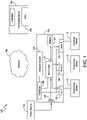
- FIG. 1 is a block diagram of a network system 100 including an Uninterruptible Power Supply (UPS) system 101 in accordance with aspects of the present invention.
- the UPS system 101 includes a power input 115, power circuitry 117, a network module 102, one or more power outputs (such as a first output 103, a second output 104, a third output 105, etc.). a controller 106, and a battery 107.
- the controller 106 is coupled to the first output 103, the second output 104, the third output 105, and the network module 102.
- the controller 106 is also coupled to the power circuitry 117.
- the network module 102 is configured to be coupled to an external computing device, such as a management system 110 via a network 108.
- the first output 103 is configured to be coupled to a first load 111.
- the second output 104 is configured to be coupled to a second load 112.
- the third output 105 is configured to be coupled to a third load 113.
- the power input 115 of the UPS 101 is configured to be coupled to a power source 114.
- the power circuitry 117 is coupled between the power input 115 and the outputs 103, 104, 105.
- the power circuitry 117 is also coupled to the battery 107. Certain embodiments may include more or fewer outputs.
- Power outputs may be in the form of an outlet or other electromechanical coupling or may include power outputs in forms other than an outlet, for example, as a hard-wired connection or a switchable connection, and may be user-disconnectable or may not be user-disconnectable. Additionally, power outputs may provide alternating current (AC) or direct current (DC), such as to rack-mounted equipment supplied with rack power or with power integrated to the rack. AC or DC type, voltages, and the like may be configurable per power output.
- AC alternating current
- DC direct current
- the UPS 101 is configured to receive, at the input 115, input power from the power source 114. If the controller 106 determines that the input power is acceptable (e.g., at least at a desired level), the controller 106 operates the power circuitry 117 to provide desired output power to each output 103, 104, 105 derived from the input power. If the input power is acceptable, the controller 106 may also operate the power circuitry 117 to provide power to the battery 107 to charge the battery 107. If the controller 106 determines that the input power is unacceptable (e.g., below the desired level), the controller 106 operates the power circuitry 117 to provide desired output power to each output 103, 104, 105 derived from backup power provided by the battery 107. According to one embodiment, the power circuitry 117 includes conversion circuitry (e.g., at least one converter and/or an inverter) that is operated by the controller 106 to generate regulated output power from the input power and/or the backup power.
- conversion circuitry e.g., at least one
- the controller 106 may be configured to communicate with the management system 110 via the network module 102 and the network 108.
- the management system 110 is a computing device such as an operator's computer system; however, in other embodiments, the management system 110 may be any other type of system capable of communicating with the UPS 101 (e.g., a mobile phone, tablet computer, etc.).
- the network 108 is the Internet; however, in other embodiments, the network 108 may be any other type of Wide Area Network (WAN).
- the network 108 is a Local Area Network (LAN).
- the network 108 may be any other type of network capable of facilitating communication between the UPS 101 and the management system 110.
- the controller 106 is configured to communicate with any other type of management system that is configured to provide signals to the UPS 101 to control operation of the UPS 101.
- the controller 106 is configured to communicate with any number of different external systems (e.g., computing devices, management systems, etc.) via the network module 102 and the network 108, or the controller 106 may not communicate with external systems (e.g., the controller 106 may be statically pre-configured or may be locally configured via a local user interface).
- the controller 106 may provide a UPS management UI to the management system 110 via the network module 102 and the network 108.
- the UPS management UI is displayed to an operator via a Video Display Unit (VDU) 109.
- the operator can interact with the UPS management UI via an interface (e.g., a keypad, touchpad, keyboard, mouse, etc.) of the management system 110.
- the UPS management UI allows the operator to select feature options appropriate for each power output (e.g., outputs 103, 104, 105), such as what action to take in response to determining a network failure, such as enabling a power output, disabling a power output, or cycling a power output, for example.
- the UPS 101 includes a mix of static and dynamic outputs, which may include individual outputs.
- a static output is an output that is permanently configured to be coupled to a certain type of load, and therefore permanently configured to perform a certain action in response to determining a network failure.
- the first output 103 of the UPS 101 is a static output permanently configured to be coupled to a piece of network equipment suitable for rebooting during a network failure
- the third output 105 is a static output permanently configured to be coupled to a piece of non-network equipment not suitable for rebooting during a network failure.
- the second output 104 is a dynamic output which may be identified, by the operator, as being coupled to a network or non-network piece of equipment, or may be configured, by the operator, to perform a certain action in response to determining a network failure.
- the UPS 101 may include any number of static and/or dynamic outputs.
- a rebooting feature e.g., a "Watchdog" feature
- a controller coupled to network equipment attempts to communicate with a remote server at predetermined times. If the controller is unable to communicate with the remote server, the controller determines that there is a connectivity issue and cycles power to the power output, which may reboot a piece of network equipment coupled to and powered by the power output.
- One or more remote servers may be part of a primary cloud service that supports checking of network connectivity by responding to client connection requests.
- the primary cloud service may include dedicated and non-dedicated servers for the purpose of checking connectivity by responding to client requests.
- the primary cloud service may not be available at some times, however, due to reasons other than a failure in network connectivity.
- the primary cloud service may be unavailable because of a failure at the primary cloud service even though regular network connectivity is otherwise operational, e.g., other services and network connected equipment may be reachable. If a test for network connectivity operates by only attempting to communicate with the primary cloud service, the robustness of the system is limited in that if the cloud service is unavailable, the networking equipment may be restarted unnecessarily, impacting network connectivity.
- Embodiments described herein provide a network connectivity confirmation system that utilizes multiple servers and protocols, dedicated and non-dedicated, to confirm network connectivity. By using multiple servers and protocols, each of different types, the system provides enhanced network resilience.
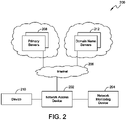
- FIG. 2 is a block diagram of one embodiment of a network connectivity confirmation system 200.
- the system 200 includes a network access device 202, a network monitoring device 204, and a primary cloud service comprised of one or more primary (and optional secondary) servers 208.
- the network monitoring device 204 is coupled to the network access device 202.
- the network access device 202 is configured to allow communication with the primary servers 208 via a network 206.
- the network 206 is the Internet; however, in other embodiments, the network 206 may be any type of LAN or WAN.
- the network access device 202 is a piece of network equipment (e.g., a server, router, switch, etc.) that provides network 206 access to other devices, such as device 210.
- the network access device 202 is a piece of network equipment that is coupled to a network configured output of the UPS 101 described above with regard to FIG. 1 ; however, in other embodiments, the network access device 202 may be any other type of network access device that provides network excess to other devices, and may be included within or provided in combination with a UPS or a network monitoring device.
- the network monitoring device 204 is configured to communicate with the network 206 via the network access device 202. According to one embodiment, the network monitoring device 204 is also able to control power supplied to the network access device 202.
- the network monitoring device 204 is located in a UPS (e.g., the UPS 101 discussed above with regard to FIG. 1 ) to which the network access device 202 is coupled.
- the network monitoring device 204 is located in the controller 106 of the UPS 101 or is otherwise in communication with the controller 106; however, in other embodiments, the network monitoring device 204 may be located in the network access device 202 or configured in some other appropriate way.
- the network monitoring device 204 In determining the status of the network 206, the network monitoring device 204 periodically tests network connectivity to the primary cloud service by attempting to communicate with the primary servers 208.
- the primary servers 208 are servers in which one function of the server is to determine the operational status of the network 206 (i.e., by responding to communications from the network monitoring device 204).
- the network monitoring device 204 may attempt to communicate with additional servers that are part of the primary cloud service. If the network monitoring device 204 is unsuccessful at communicating with any of the servers of the primary cloud service, the network monitoring device 204 may declare the primary cloud service unreachable.
- the primary cloud service may be unreachable because of a problem with connectivity through the network 206, or the primary cloud service may be unreachable because of an issue at the primary cloud service.
- the network monitoring device 204 uses an additional method to check for network connectivity more generally.
- the additional method involves using a Domain Name Service (DNS) query to check for connectivity to one or more domain name servers 212 otherwise reachable via the network 206. If after failing to communicate with the primary cloud service, the network monitoring device 204 is unsuccessful at communicating with a domain name server 212, the network monitoring device 204 then identifies that there is a problem with the network 206. Upon identifying that there is a problem with the network 206, the network monitoring device 204 may notify the operator, cycle power to the network access device 202, or take some other appropriate action.
- DNS Domain Name Service
- FIG. 3 is a flow chart illustrating one embodiment of a network connectivity confirmation process 300 implemented by the system 200.
- the network monitoring device 204 determines whether there is a connection to a primary cloud service, e.g., by attempts to communicate with the primary cloud service (i.e., by transmitting a signal to one of the primary servers 208) via the network access device 202 and the network 206.
- the network monitoring device 204 attempts to communicate with the primary cloud service by utilizing the Transmission Control Protocol (TCP) and/or the User Datagram Protocol (UDP); however, in other embodiments, the network monitoring device 204 may utilize some other protocol to communicate with the primary cloud service.
- TCP Transmission Control Protocol
- UDP User Datagram Protocol
- the network monitoring device 204 determines that the network 206 is operating correctly and resets any wait period and/or failure counts at block 304. After a period of time, the network monitoring device 204 may attempt to communicate with the primary cloud service again (at block 302). In one embodiment, the period of time between connection attempts is configurable by the operator. According to one embodiment, a connection established between the network monitoring device 204 and a primary server 208, via the network 206 and the network access device 202, is secure.
- the network monitoring device 204 may track a delay time during which the network monitoring device will continue to check for ability to communicate with the primary cloud service (at block 302). If the network monitoring device 204 continues to be unable to communicate with the primary cloud service until the end of the delay period (at block 306), the network monitoring device 204 performs a DNS lookup at block 308.
- the DNS lookup at block 308 includes sending a domain name query to a domain name server, such as one of the domain name servers 212, and monitoring for a response from the domain name server.
- Domain name servers resolve domain names into Internet Protocol (IP) addresses upon request.
- IP Internet Protocol
- Domain name servers are operated privately and publicly. There are numerous publicly accessible domain name servers routinely available on the Internet infrastructure. Some domain name servers are particularly well known and many domain name servers are operated by companies that provide significant Internet and World Wide Web services. Due to the nature of some domain name servers and the significant service offerings provided by the companies that provide them, availability of such domain name servers, e.g., domain name servers 212, may far exceed the availability of the primary servers 208. Therefore domain name servers may provide significant backup capability for determining network connectivity when communication with a primary cloud service fails.
- the network monitoring device 204 may perform multiple DNS lookups, i.e., by sending DNS queries to more than one remote domain name server, and a response from any one of the domain name servers may be sufficient to confirm that network 206 is operational, providing additional reliability to the determination of network connectivity.
- the network monitoring device 204 may be pre-configured with particular IP addresses of known domain name servers so that the network monitoring device 204 may send the DNS query directly to one or more domain name servers, thereby bypassing any local network equipment that might otherwise locally respond to the DNS query.
- the network monitoring device may send DNS queries to an otherwise assigned domain name server, such as by an IP address assigned through Dynamic Host Configuration Protocol (DHCP).
- DHCP Dynamic Host Configuration Protocol
- one or more DNS queries may be sent in accord with any one or combination of DNS configurations.
- the network monitoring device 204 determines that the network 206 is functioning and returns to testing connectivity to the primary cloud service (at block 302). If the DNS lookup is not successful (at block 310), the network monitoring device 204 increments a failure count and resets a checking delay at block 312 and determines whether the failure count has reached a limit (at block 314). At block 316, responsive to the failure count reaching a limit, the network monitoring device 204 determines that network 206 connectivity has failed.
- the failure count limit may be ten failures, but in other embodiments it may be more or fewer failures and may be configurable by an operator.
- the network monitoring device 204 may directly declare a network failure (at block 316) without keeping track of failure counts or delays.
- the network monitoring device 204 Responsive to the network monitoring device 204 determining that the network 206 has failed (at block 316), the network monitoring device 204 will attempt corrective action(s) to fix the network 206, for example by performing a power cycle at block 318 to reset one or more network access devices, such as network access device 202.
- the network connectivity confirmation process 300 may be selectively implemented in a network configured output of the UPS 101 (shown in FIG. 1 ) and upon determining that the network 206 has failed, the network monitoring device 204 may send a command to the controller 106 to cycle power to the output of the UPS 101 to which the network access device 202 is coupled. Cycling power causes the network access device 202 to reset by rebooting.
- the network connectivity confirmation process 300 may control a network configured output of another type of power device (e.g., a power strip, a smart outlet, etc.).
- the network monitoring device 204 may optionally increment a counter of power cycles (at block 320) and not perform further power cycles after the cycle counter reaches a limit (at block 322).
- the network monitoring device 204 may generate a delay (at block 324) between successive determinations of network failure and subsequent power cyclings, and may generate a longer delay (at block 326) when successive power cyclings have failed to resolve the network 206 failure. Additionally, the network monitoring device 204 may successively increase waiting delays (at block 328) between successive checking for network 206 connectivity based on the number of iterative times the network 206 has been determined to be in failure (at block 316).
- the network monitoring device 204 may take different corrective measures. For example, in some embodiments the network monitoring device 204 may transmit a message to the management system 110, may provide a message to an operator's display, or may operate some type of indicator (e.g., a light, sound generator etc.) to indicate that there is a network problem. In other embodiments, upon determining that the network 206 has failed, the network monitoring device 204 performs network analytics on the resulting data.
- some type of indicator e.g., a light, sound generator etc.
- the network connectivity confirmation process 300 is implemented in a UPS; however, in other embodiments, the network connectivity confirmation process is implemented in some other network monitoring peripheral or some other power device (e.g., a power strip, smart outlet, or other device having capability to control power to the network access device, etc.).
- some other network monitoring peripheral or some other power device e.g., a power strip, smart outlet, or other device having capability to control power to the network access device, etc.
- the network monitoring device 204 is configured to attempt communication with a domain name server only after communication has failed with the primary cloud service a predetermined number of times and/or for a predetermined amount of time; however, in other embodiments, the network monitoring device 204 may be configured to attempt communication with one or more domain name servers immediately after a communication failure with the primary cloud service. Similarly, the network monitoring device 204 is configured to identify a network failure only after communication has failed with the domain name server(s) a predetermined number of times; however, in other embodiments, the network monitoring device 204 may identify a network failure immediately after a communication failure with one or more domain name servers.
- the network connectivity confirmation process 300 may be a selectable feature to control a power source to a network device, such as to control a power output coupled to the network device.
- An operator may selectively enable the connectivity confirmation process 300 to control an output of a power device, such as a UPS, an outlet strip, a smart outlet, etc. Additionally, the operator may choose not to implement the feature and turn the feature off with respect to one or more power outputs.
- network failure is identified after communication attempts to both a primary cloud service and a domain name server have failed; however, in at least one embodiment, a network failure may be identified after communication to a single server or service fails.
- communication is attempted with a single primary cloud service before communication with a domain name server is attempted; however, in other embodiments, communication may be attempted with multiple or no cloud services before communication is attempted with a domain name server, and communication attempts with any cloud service may include communication attempts with one or more primary servers and/or one or more secondary servers.
- Embodiments described herein provide a network connectivity confirmation system that utilizes multiple servers, including a domain name server, to confirm network connectivity.
- domain name servers including third party domain name servers having high availability, rather than only a primary cloud service, the system provides enhanced network resilience.
- FIG. 4 illustrates an example block diagram of computing components forming a system 400 which may be configured to implement the aspects disclosed herein.
- the system 400 is included within a controller 106, and configured to check the connectivity status of a network as discussed above.
- the system 400 may include for example a computing platform such as those based on Intel PENTIUM-type processor, Motorola PowerPC, Sun UltraSPARC, Texas Instruments-DSP, Hewlett-Packard PA-RISC processors, ARM-Cortex M series processors, or any other type of processor or microcontroller.
- System 400 may include specially-programmed, special-purpose hardware, for example, an application-specific integrated circuit (ASIC).
- ASIC application-specific integrated circuit
- Various aspects of the present disclosure may be implemented as specialized software executing on the system 400 such as that shown in FIG. 4 .
- the system 400 may include a processor/ASIC 406 connected to one or more memory devices 410, such as a disk drive, memory, flash memory, embedded or on-chip memory, or other device for storing data.
- Memory 410 may be used for storing programs and data during operation of the system 400.
- Components of the computer system 400 may be coupled by an interconnection mechanism 408, which may include one or more buses (e.g., between components that are integrated within a same machine) and/or a network (e.g., between components that reside on separate machines).
- the interconnection mechanism 408 enables communications (e.g., data, instructions) to be exchanged between components of the system 400.
- the system 400 also includes one or more input devices 404, which may include for example, a keyboard, a mouse, or a touch screen.
- the system 400 includes one or more output devices 402, which may include for example a display.
- the computer system 400 may contain one or more interfaces (not shown) that may connect the computer system 400 to a communication network, in addition to or as an alternative to the interconnection mechanism 408.
- the system 400 may include a storage system 412, which may include a computer readable and/or writeable nonvolatile medium in which signals may be stored to provide a program to be executed by the processor or to provide information stored on or in the medium to be processed by the program.
- the medium may, for example, be a disk or flash memory and in some examples may include RAM or other non-volatile memory such as EEPROM.
- the processor may cause data to be read from the nonvolatile medium into another memory 410 that allows for faster access to the information by the processor/ASIC 406 than does the medium.
- This memory 410 may be a volatile, random access memory such as a dynamic random access memory (DRAM) or static memory (SRAM).
- DRAM dynamic random access memory
- SRAM static memory
- the processor 406 may manipulate the data within the integrated circuit memory 410 and then copy the data to the storage 412 after processing is completed.
- a variety of mechanisms are known for managing data movement between storage 412 and the integrated circuit memory element 410, and the disclosure is not limited thereto. The disclosure is not limited to a particular memory system 410 or storage system 412.
- the system 400 may include a computer platform that is programmable using a high-level computer programming language.
- the system 400 may be also implemented using specially programmed, special purpose hardware, e.g. an ASIC.
- the system 400 may include a processor 406, which may be a commercially available processor such as the well-known Pentium class processor available from the Intel Corporation. Many other processors are available.
- the processor 406 may execute an operating system which may be, for example, a Windows operating system available from the Microsoft Corporation, MAC OS System X available from Apple Computer, the Solaris Operating System available from Sun Microsystems, or UNIX and/or LINUX available from various sources. Many other operating systems may be used, including bare metal and/or virtual computing systems.
- the processor and operating system together may form a computer platform for which application programs in high-level programming languages may be written. It should be understood that the disclosure is not limited to a particular computer system platform, processor, operating system, or network. Also, it should be apparent to those skilled in the art that the present disclosure is not limited to a specific programming language or computer system. Further, it should be appreciated that other appropriate programming languages and other appropriate computer systems could also be used.
- an uninterruptible power supply has a controller and a network module, and the UPS controls the power provided to a network access device through a power output, such as via an outlet, direct power connection, or integrated rack power.
- the controller includes a processor, which may be any of the above or other suitable processors, including ASICs, which runs an instruction set or operates upon other logic, to implement a network connectivity confirmation process as discussed above.
- the controller thereby attempts communication with a primary cloud service, e.g., at least one primary server, and upon a failure condition to communicate with the primary cloud service the controller attempts communication with at least one domain name server.
- the controller may cycle power to the network access device to force the network access device to reboot, in an attempt to restore network connectivity.
- Various failure conditions may be used and include failure counts, delay times, timeouts, and the like.
- Attempted communication with a primary cloud service may include attempted communication with a primary server, an alternate primary server, a secondary server, etc., including multiples or alternate combinations of such servers.
- UPS may be used to provide regulated, uninterrupted power for sensitive and/or critical loads, such as computer systems and other data processing systems.
- Known uninterruptible power supplies include on-line UPS's, off-line UPS's, line interactive UPS's, as well as others. Uninterruptible power supplies may provide AC or DC output and may provide power regulation or may be unregulated.
- On-line UPS's provide conditioned power as well as back-up power upon interruption of a primary source of power.
- Off-line UPS's typically do not provide conditioning of input power, but do provide back-up power upon interruption of the primary power source.
- Line interactive UPS's are similar to off-line UPS's in that they switch to battery power when a blackout occurs but also typically include a multi-tap transformer for regulating the output voltage provided by the UPS.
- Typical UPS's may also operate in a bypass mode where unconditioned power with basic protection is provided directly from a power source to a load via a bypass line.
Landscapes
- Engineering & Computer Science (AREA)
- Theoretical Computer Science (AREA)
- Signal Processing (AREA)
- Computer Networks & Wireless Communication (AREA)
- General Engineering & Computer Science (AREA)
- Power Engineering (AREA)
- Physics & Mathematics (AREA)
- General Physics & Mathematics (AREA)
- Environmental & Geological Engineering (AREA)
- Computer Hardware Design (AREA)
- Emergency Management (AREA)
- Business, Economics & Management (AREA)
- Human Computer Interaction (AREA)
- Remote Monitoring And Control Of Power-Distribution Networks (AREA)
- Power Sources (AREA)
Claims (15)
- Eine Stromvorrichtung (101), die Folgendes beinhaltet:einen Eingang (115), der konfiguriert ist, um mit einer Stromquelle gekoppelt zu sein und um von der Stromquelle (114) Eingangsstrom zu empfangen;eine Stromschaltung (117), die mit dem Eingang (115) gekoppelt ist;einen Stromausgang (103, 104, 105), der mit der Stromschaltung (117) gekoppelt ist;ein Netzmodul (102), das konfiguriert ist, um mit einem Netz (108) gekoppelt zu sein;
undeine Steuereinheit (106), die mit dem Stromausgang (103, 104, 105), der Stromschaltung (117) und dem Netzmodul (102) gekoppelt ist, wobei die Steuereinheit (106) für Folgendes konfiguriert ist:Betreiben der Stromschaltung (117), um dem Stromausgang (103, 104, 105) von dem Eingangsstrom abgeleiteten Ausgangsstrom bereitzustellen;Versuchen des Kommunizierens mit einem primären Cloud-Dienst, der mindestens einen Server umfasst, über eine Netzzugangsvorrichtung (202);als Reaktion auf eine Feststellung, dass die Kommunikation mit dem primären Cloud-Dienst fehlgeschlagen ist, Versuchen des Kommunizierens mit mindestens einem fremden Domain-Name-Server (212) über die Netzzugangsvorrichtung (202); undals Reaktion auf eine Feststellung, dass die Kommunikation mit dem primären Cloud-Dienst und dem mindestens einen fremden Domain-Name-Server (212) fehlgeschlagen ist, Identifizieren, dass das Netz (108) ausgefallen ist. - Stromvorrichtung (101) gemäß Anspruch 1, wobei als Reaktion auf das Identifizieren, dass das Netz (108) ausgefallen ist, die Steuereinheit (106) ferner konfiguriert ist, um Strom zu dem Stromausgang (103, 104, 105) aus- und wieder einzuschalten.
- Stromvorrichtung (101) gemäß Anspruch 2, wobei die Steuereinheit (106) ferner konfiguriert ist, um jedes Mal, wenn Strom zu dem Stromausgang (103, 104, 105) aus- und wieder eingeschaltet wird, einen Zähler zu erhöhen.
- Stromvorrichtung (101) gemäß Anspruch 1, wobei die Steuereinheit (106) ferner konfiguriert ist, um über eine Managementschnittstelle von einem Betreiber eine Angabe, ob die Netzzugangsvorrichtung (202) oder eine netzfreie Vorrichtung mit dem Stromausgang (103, 104, 105) gekoppelt ist, zu empfangen.
- Stromvorrichtung (101) gemäß Anspruch 4, wobei als Reaktion auf das Identifizieren, dass das Netz (108) ausgefallen ist, die Steuereinheit (106) ferner konfiguriert ist, um als Reaktion darauf, dass der Stromausgang (103, 104, 105) als mit der Netzzugangsvorrichtung (202) gekoppelt angegeben wird, Strom zu dem Stromausgang (103, 104, 105) aus- und wieder einzuschalten.
- Stromvorrichtung (101) gemäß Anspruch 1, wobei die Steuereinheit (106) ferner konfiguriert ist, um einem Managementsystem eine Managementschnittstelle bereitzustellen und über die Managementschnittstelle eine Vielzahl von Netzkonfigurationsoptionen anzuzeigen.
- Stromvorrichtung (101) gemäß Anspruch 6, wobei mindestens eine Netzkonfigurationsoption eine Neustarteinrichtungs-Implementierungsoption umfasst und als Reaktion auf das Auswählen der Neustarteinrichtungs-Implementierungsoption in Bezug auf den Stromausgang (103, 104, 105) über die Managementschnittstelle die Steuereinheit (106) ferner konfiguriert ist, um den Stromausgang (103, 104, 105) so zu betreiben, dass er als Reaktion auf das Identifizieren, dass das Netz (108) ausgefallen ist, Strom aus- und wieder einschaltet.
- Stromvorrichtung (101) gemäß Anspruch 1, wobei als Reaktion auf das Identifizieren, dass das Netz (108) ausgefallen ist, die Steuereinheit (106) ferner konfiguriert ist, um mindestens eines vom Aktivieren des Stromausgangs (103, 104, 105), Deaktivieren des Stromausgangs (103, 104, 105) und Aus- und wieder Einschalten von Strom zu dem Stromausgang (103, 104, 105) durchzuführen.
- Ein Verfahren zum Steuern von Strom zu einer Netzzugangsvorrichtung (202), wobei das Verfahren Folgendes beinhaltet:periodisches Prüfen, durch eine Steuereinheit (106) über die Netzzugangsvorrichtung (202), eines Status einer Netzverbindung, umfassend das Versuchen des Kommunizierens mit einem primären Cloud-Dienst, der mindestens einen Server umfasst, und Senden, als Reaktion auf eine Feststellung, dass die Kommunikation mit dem primären Cloud-Dienst fehlgeschlagen ist, einer Domain-Name-Anfrage an mindestens einen fremden Domain-Name-Server (212); undSteuern, durch die Steuereinheit (106), eines mit der Netzzugangsvorrichtung (202) gekoppelten Stromausgangs (103, 104, 105), um als Reaktion auf das Fehlschlagen des Kommunizierens mit dem primären Cloud-Dienst und das Fehlschlagen des Empfangens einer Antwort auf die Domain-Name-Anfrage Strom zu der Netzzugangsvorrichtung (202) vorübergehend zu unterbrechen.
- Verfahren gemäß Anspruch 9, das ferner Folgendes beinhaltet:Bereitstellen, durch die Steuereinheit (106), einer Managementschnittstelle für einen Betreiber; undEmpfangen, durch die Steuereinheit (106) über die Managementschnittstelle, einer Angabe des mit der Netzzugangsvorrichtung (202) gekoppelten Stromausgangs (103, 104, 105).
- Verfahren gemäß Anspruch 9, das ferner das Angeben eines Netzausfalls als Reaktion auf das Fehlschlagen des Kommunizierens mit dem primären Cloud-Dienst und das Fehlschlagen des Empfangens einer Antwort von dem mindestens einen fremden Domain-Name-Server (212) beinhaltet, umfassend mindestens eines von Bewirken, dass eine Warnnachricht angezeigt wird, Beleuchten eines visuellen Anzeigers und Ertönenlassen eines hörbaren Anzeigers.
- Verfahren gemäß Anspruch 9, das ferner Folgendes beinhaltet:Bereitstellen von Ausgangsstrom zu dem Stromausgang (103, 104, 105) durch eine Stromschaltung (117), die konfiguriert ist, um den Ausgangsstrom von einem Eingangsstrom abzuleiten;Detektieren eines Zustands des Eingangsstroms; undBereitstellen des Ausgangsstroms durch die Stromschaltung (117) von einer alternativen Stromquelle als Reaktion darauf, dass ein Zustand des Eingangsstroms inakzeptabel ist.
- Verfahren gemäß Anspruch 9, das ferner das Vergrößern einer Verzögerung zwischen dem periodischen Prüfen des Status des Netzes (108) auf der Basis darauf, wie oft der Strom vorübergehend unterbrochen wurde, beinhaltet.
- Verfahren gemäß Anspruch 9, wobei das Senden einer Domain-Name-Anfrage an den mindestens einen fremden Domain-Name-Server (212) das Senden einer oder mehrerer Domain-Name-Anfragen an eine Vielzahl von Domain-Name-Servern (212) umfasst, wobei eine Antwort von einem beliebigen der Vielzahl von Domain-Name-Servern (212) eine Antwort auf die Domain-Name-Anfrage ist.
- Ein computerlesbares Medium, das Anweisungen beinhaltet, die, wenn durch einen Computer ausgeführt, bewirken, dass der Computer das Verfahren gemäß einem der Ansprüche 9 bis 14 vollzieht.
Applications Claiming Priority (1)
| Application Number | Priority Date | Filing Date | Title |
|---|---|---|---|
| US15/434,129 US10439914B2 (en) | 2017-02-16 | 2017-02-16 | System and method to determine and repair network connection problems |
Publications (2)
| Publication Number | Publication Date |
|---|---|
| EP3364518A1 EP3364518A1 (de) | 2018-08-22 |
| EP3364518B1 true EP3364518B1 (de) | 2022-11-09 |
Family
ID=61231165
Family Applications (1)
| Application Number | Title | Priority Date | Filing Date |
|---|---|---|---|
| EP18157217.3A Active EP3364518B1 (de) | 2017-02-16 | 2018-02-16 | System und verfahren zum erkennen und reparieren von netzwerkverbindungsproblemen |
Country Status (3)
| Country | Link |
|---|---|
| US (1) | US10439914B2 (de) |
| EP (1) | EP3364518B1 (de) |
| CN (2) | CN113973067B (de) |
Families Citing this family (3)
| Publication number | Priority date | Publication date | Assignee | Title |
|---|---|---|---|---|
| MX377369B (es) * | 2015-09-28 | 2025-03-10 | Andrew Wireless Systems Uk Ltd | Simulación de respuesta de sistema de nombres de dominio en el dispositivo de equipo de la instalación del cliente. |
| US10313179B1 (en) * | 2017-04-26 | 2019-06-04 | Sprint Communications Company L.P. | Systems and methods for network element access analysis, collision avoidance, and fault resolution |
| JP2023036274A (ja) * | 2021-09-02 | 2023-03-14 | 富士フイルムビジネスイノベーション株式会社 | 情報処理装置、情報処理システム、及び情報処理プログラム |
Family Cites Families (12)
| Publication number | Priority date | Publication date | Assignee | Title |
|---|---|---|---|---|
| JP2007241827A (ja) * | 2006-03-10 | 2007-09-20 | Densei Lambda Kk | 無停電電源装置、無停電電源システムおよびシャットダウン処理プログラム |
| US8365018B2 (en) * | 2007-06-19 | 2013-01-29 | Sand Holdings, Llc | Systems, devices, agents and methods for monitoring and automatic reboot and restoration of computers, local area networks, wireless access points, modems and other hardware |
| KR100949814B1 (ko) * | 2007-12-20 | 2010-03-30 | 성신전기공업(주) | 무정전전원장치의 통합 원격 감시 시스템 |
| US20100267390A1 (en) * | 2008-09-04 | 2010-10-21 | Gao Lin | Fault-tolerant, multi-network detour router system for text messages, data, and voice |
| US7987392B2 (en) * | 2009-06-08 | 2011-07-26 | Microsoft Corporation | Differentiating connectivity issues from server failures |
| CN101826996B (zh) * | 2010-03-19 | 2012-05-23 | 中国科学院计算机网络信息中心 | 域名系统流量检测方法与域名服务器 |
| US8627123B2 (en) * | 2010-03-25 | 2014-01-07 | Microsoft Corporation | Managing power provisioning in distributed computing |
| US8204990B1 (en) | 2011-10-06 | 2012-06-19 | James Avery | Power cycler with internet connectivity monitor |
| WO2014163604A1 (en) | 2013-03-31 | 2014-10-09 | Schneider Electric It Corporation | System and method for configuring ups outlets |
| CN104506893B (zh) * | 2014-12-15 | 2018-02-16 | 四川长虹电器股份有限公司 | 一种信息更新方法、云端服务器及crm服务器 |
| CN104901834A (zh) * | 2015-05-20 | 2015-09-09 | 广东睿江科技有限公司 | 一种网络服务器自动切换的方法及系统 |
| US9847672B2 (en) | 2015-06-15 | 2017-12-19 | Schneider Electric It Corporation | System and method to improve network reliability |
-
2017
- 2017-02-16 US US15/434,129 patent/US10439914B2/en active Active
-
2018
- 2018-02-16 EP EP18157217.3A patent/EP3364518B1/de active Active
- 2018-02-22 CN CN202111106403.0A patent/CN113973067B/zh active Active
- 2018-02-22 CN CN201810153801.XA patent/CN108449225B/zh active Active
Also Published As
| Publication number | Publication date |
|---|---|
| EP3364518A1 (de) | 2018-08-22 |
| US10439914B2 (en) | 2019-10-08 |
| CN108449225B (zh) | 2021-10-15 |
| CN113973067A (zh) | 2022-01-25 |
| CN108449225A (zh) | 2018-08-24 |
| CN113973067B (zh) | 2024-04-30 |
| US20180234313A1 (en) | 2018-08-16 |
Similar Documents
| Publication | Publication Date | Title |
|---|---|---|
| US10491704B2 (en) | Automatic provisioning of cloud services | |
| US9791908B2 (en) | Systems and methods for protecting virtualized assets | |
| CN108206847B (zh) | Cdn管理系统、方法及装置 | |
| AU2010229495B2 (en) | System and method for altering a user interface of a power device | |
| CN101938368A (zh) | 刀片服务器系统中的虚拟机管理器和虚拟机处理方法 | |
| US20140136866A1 (en) | Rack and power control method thereof | |
| US10439914B2 (en) | System and method to determine and repair network connection problems | |
| JP2020115330A (ja) | ソフトウエアアプリケーションプロセスを監視するシステムと方法 | |
| US20150264184A1 (en) | Conference terminal control system, conference terminal control device, and conference terminal control method | |
| AU2010229206A1 (en) | System and method for configuring a power device | |
| CN112637335A (zh) | 主备模式服务部署方法、装置、设备及存储介质 | |
| WO2022139951A1 (en) | Overloading a boot error signaling mechanism to enable error mitigation actions to be performed | |
| US9727104B2 (en) | Various PSUs adaptive server and method | |
| US8150958B2 (en) | Methods, systems and computer program products for disseminating status information to users of computer resources | |
| WO2020088351A1 (zh) | 设备信息发送的方法、计算机设备和分布式计算机设备系统 | |
| US8533528B2 (en) | Fault tolerant power sequencer | |
| CN116820686A (zh) | 物理机的部署方法、虚拟机和容器统一监控的方法及装置 | |
| JP6789685B2 (ja) | ネットワークの信頼性を改善するシステム又は方法 | |
| CN110456897A (zh) | 电子设备的掉电保护方法、保护装置及服务器集群 | |
| US10904400B2 (en) | Information processing apparatus and non-transitory computer readable medium for determining a response to corrective step | |
| US9665449B2 (en) | Apparatus and method for setting information to a replaceable device installed in a device | |
| CN117692113A (zh) | 一种控制器的热备冗余方法、装置、设备及存储介质 | |
| JP2004157738A (ja) | 無停電電源装置、並びに、無停電電源装置を利用したコンピュータシステムおよびコンピュータの起動段階監視方法 | |
| HK1142747B (en) | Method and system for determining physical location of equipment |
Legal Events
| Date | Code | Title | Description |
|---|---|---|---|
| PUAI | Public reference made under article 153(3) epc to a published international application that has entered the european phase |
Free format text: ORIGINAL CODE: 0009012 |
|
| STAA | Information on the status of an ep patent application or granted ep patent |
Free format text: STATUS: THE APPLICATION HAS BEEN PUBLISHED |
|
| AK | Designated contracting states |
Kind code of ref document: A1 Designated state(s): AL AT BE BG CH CY CZ DE DK EE ES FI FR GB GR HR HU IE IS IT LI LT LU LV MC MK MT NL NO PL PT RO RS SE SI SK SM TR |
|
| AX | Request for extension of the european patent |
Extension state: BA ME |
|
| STAA | Information on the status of an ep patent application or granted ep patent |
Free format text: STATUS: REQUEST FOR EXAMINATION WAS MADE |
|
| 17P | Request for examination filed |
Effective date: 20190222 |
|
| RBV | Designated contracting states (corrected) |
Designated state(s): AL AT BE BG CH CY CZ DE DK EE ES FI FR GB GR HR HU IE IS IT LI LT LU LV MC MK MT NL NO PL PT RO RS SE SI SK SM TR |
|
| STAA | Information on the status of an ep patent application or granted ep patent |
Free format text: STATUS: EXAMINATION IS IN PROGRESS |
|
| 17Q | First examination report despatched |
Effective date: 20200730 |
|
| GRAP | Despatch of communication of intention to grant a patent |
Free format text: ORIGINAL CODE: EPIDOSNIGR1 |
|
| STAA | Information on the status of an ep patent application or granted ep patent |
Free format text: STATUS: GRANT OF PATENT IS INTENDED |
|
| RIC1 | Information provided on ipc code assigned before grant |
Ipc: G06F 1/26 20060101ALI20220222BHEP Ipc: H02J 13/00 20060101ALI20220222BHEP Ipc: H02J 9/06 20060101AFI20220222BHEP |
|
| INTG | Intention to grant announced |
Effective date: 20220307 |
|
| GRAJ | Information related to disapproval of communication of intention to grant by the applicant or resumption of examination proceedings by the epo deleted |
Free format text: ORIGINAL CODE: EPIDOSDIGR1 |
|
| STAA | Information on the status of an ep patent application or granted ep patent |
Free format text: STATUS: EXAMINATION IS IN PROGRESS |
|
| GRAP | Despatch of communication of intention to grant a patent |
Free format text: ORIGINAL CODE: EPIDOSNIGR1 |
|
| STAA | Information on the status of an ep patent application or granted ep patent |
Free format text: STATUS: GRANT OF PATENT IS INTENDED |
|
| INTC | Intention to grant announced (deleted) | ||
| INTG | Intention to grant announced |
Effective date: 20220602 |
|
| GRAS | Grant fee paid |
Free format text: ORIGINAL CODE: EPIDOSNIGR3 |
|
| GRAA | (expected) grant |
Free format text: ORIGINAL CODE: 0009210 |
|
| STAA | Information on the status of an ep patent application or granted ep patent |
Free format text: STATUS: THE PATENT HAS BEEN GRANTED |
|
| AK | Designated contracting states |
Kind code of ref document: B1 Designated state(s): AL AT BE BG CH CY CZ DE DK EE ES FI FR GB GR HR HU IE IS IT LI LT LU LV MC MK MT NL NO PL PT RO RS SE SI SK SM TR |
|
| REG | Reference to a national code |
Ref country code: GB Ref legal event code: FG4D |
|
| REG | Reference to a national code |
Ref country code: CH Ref legal event code: EP Ref country code: AT Ref legal event code: REF Ref document number: 1530999 Country of ref document: AT Kind code of ref document: T Effective date: 20221115 |
|
| REG | Reference to a national code |
Ref country code: DE Ref legal event code: R096 Ref document number: 602018042760 Country of ref document: DE |
|
| RAP4 | Party data changed (patent owner data changed or rights of a patent transferred) |
Owner name: SCHNEIDER ELECTRIC IT CORPORATION |
|
| REG | Reference to a national code |
Ref country code: IE Ref legal event code: FG4D |
|
| REG | Reference to a national code |
Ref country code: LT Ref legal event code: MG9D |
|
| REG | Reference to a national code |
Ref country code: NL Ref legal event code: MP Effective date: 20221109 |
|
| REG | Reference to a national code |
Ref country code: AT Ref legal event code: MK05 Ref document number: 1530999 Country of ref document: AT Kind code of ref document: T Effective date: 20221109 |
|
| PG25 | Lapsed in a contracting state [announced via postgrant information from national office to epo] |
Ref country code: SE Free format text: LAPSE BECAUSE OF FAILURE TO SUBMIT A TRANSLATION OF THE DESCRIPTION OR TO PAY THE FEE WITHIN THE PRESCRIBED TIME-LIMIT Effective date: 20221109 Ref country code: PT Free format text: LAPSE BECAUSE OF FAILURE TO SUBMIT A TRANSLATION OF THE DESCRIPTION OR TO PAY THE FEE WITHIN THE PRESCRIBED TIME-LIMIT Effective date: 20230309 Ref country code: NO Free format text: LAPSE BECAUSE OF FAILURE TO SUBMIT A TRANSLATION OF THE DESCRIPTION OR TO PAY THE FEE WITHIN THE PRESCRIBED TIME-LIMIT Effective date: 20230209 Ref country code: LT Free format text: LAPSE BECAUSE OF FAILURE TO SUBMIT A TRANSLATION OF THE DESCRIPTION OR TO PAY THE FEE WITHIN THE PRESCRIBED TIME-LIMIT Effective date: 20221109 Ref country code: FI Free format text: LAPSE BECAUSE OF FAILURE TO SUBMIT A TRANSLATION OF THE DESCRIPTION OR TO PAY THE FEE WITHIN THE PRESCRIBED TIME-LIMIT Effective date: 20221109 Ref country code: ES Free format text: LAPSE BECAUSE OF FAILURE TO SUBMIT A TRANSLATION OF THE DESCRIPTION OR TO PAY THE FEE WITHIN THE PRESCRIBED TIME-LIMIT Effective date: 20221109 Ref country code: AT Free format text: LAPSE BECAUSE OF FAILURE TO SUBMIT A TRANSLATION OF THE DESCRIPTION OR TO PAY THE FEE WITHIN THE PRESCRIBED TIME-LIMIT Effective date: 20221109 |
|
| PG25 | Lapsed in a contracting state [announced via postgrant information from national office to epo] |
Ref country code: RS Free format text: LAPSE BECAUSE OF FAILURE TO SUBMIT A TRANSLATION OF THE DESCRIPTION OR TO PAY THE FEE WITHIN THE PRESCRIBED TIME-LIMIT Effective date: 20221109 Ref country code: PL Free format text: LAPSE BECAUSE OF FAILURE TO SUBMIT A TRANSLATION OF THE DESCRIPTION OR TO PAY THE FEE WITHIN THE PRESCRIBED TIME-LIMIT Effective date: 20221109 Ref country code: LV Free format text: LAPSE BECAUSE OF FAILURE TO SUBMIT A TRANSLATION OF THE DESCRIPTION OR TO PAY THE FEE WITHIN THE PRESCRIBED TIME-LIMIT Effective date: 20221109 Ref country code: IS Free format text: LAPSE BECAUSE OF FAILURE TO SUBMIT A TRANSLATION OF THE DESCRIPTION OR TO PAY THE FEE WITHIN THE PRESCRIBED TIME-LIMIT Effective date: 20230309 Ref country code: HR Free format text: LAPSE BECAUSE OF FAILURE TO SUBMIT A TRANSLATION OF THE DESCRIPTION OR TO PAY THE FEE WITHIN THE PRESCRIBED TIME-LIMIT Effective date: 20221109 Ref country code: GR Free format text: LAPSE BECAUSE OF FAILURE TO SUBMIT A TRANSLATION OF THE DESCRIPTION OR TO PAY THE FEE WITHIN THE PRESCRIBED TIME-LIMIT Effective date: 20230210 |
|
| PG25 | Lapsed in a contracting state [announced via postgrant information from national office to epo] |
Ref country code: NL Free format text: LAPSE BECAUSE OF FAILURE TO SUBMIT A TRANSLATION OF THE DESCRIPTION OR TO PAY THE FEE WITHIN THE PRESCRIBED TIME-LIMIT Effective date: 20221109 |
|
| PG25 | Lapsed in a contracting state [announced via postgrant information from national office to epo] |
Ref country code: SM Free format text: LAPSE BECAUSE OF FAILURE TO SUBMIT A TRANSLATION OF THE DESCRIPTION OR TO PAY THE FEE WITHIN THE PRESCRIBED TIME-LIMIT Effective date: 20221109 Ref country code: RO Free format text: LAPSE BECAUSE OF FAILURE TO SUBMIT A TRANSLATION OF THE DESCRIPTION OR TO PAY THE FEE WITHIN THE PRESCRIBED TIME-LIMIT Effective date: 20221109 Ref country code: EE Free format text: LAPSE BECAUSE OF FAILURE TO SUBMIT A TRANSLATION OF THE DESCRIPTION OR TO PAY THE FEE WITHIN THE PRESCRIBED TIME-LIMIT Effective date: 20221109 Ref country code: DK Free format text: LAPSE BECAUSE OF FAILURE TO SUBMIT A TRANSLATION OF THE DESCRIPTION OR TO PAY THE FEE WITHIN THE PRESCRIBED TIME-LIMIT Effective date: 20221109 Ref country code: CZ Free format text: LAPSE BECAUSE OF FAILURE TO SUBMIT A TRANSLATION OF THE DESCRIPTION OR TO PAY THE FEE WITHIN THE PRESCRIBED TIME-LIMIT Effective date: 20221109 |
|
| REG | Reference to a national code |
Ref country code: DE Ref legal event code: R097 Ref document number: 602018042760 Country of ref document: DE |
|
| PG25 | Lapsed in a contracting state [announced via postgrant information from national office to epo] |
Ref country code: SK Free format text: LAPSE BECAUSE OF FAILURE TO SUBMIT A TRANSLATION OF THE DESCRIPTION OR TO PAY THE FEE WITHIN THE PRESCRIBED TIME-LIMIT Effective date: 20221109 Ref country code: AL Free format text: LAPSE BECAUSE OF FAILURE TO SUBMIT A TRANSLATION OF THE DESCRIPTION OR TO PAY THE FEE WITHIN THE PRESCRIBED TIME-LIMIT Effective date: 20221109 |
|
| PLBE | No opposition filed within time limit |
Free format text: ORIGINAL CODE: 0009261 |
|
| STAA | Information on the status of an ep patent application or granted ep patent |
Free format text: STATUS: NO OPPOSITION FILED WITHIN TIME LIMIT |
|
| PG25 | Lapsed in a contracting state [announced via postgrant information from national office to epo] |
Ref country code: MC Free format text: LAPSE BECAUSE OF FAILURE TO SUBMIT A TRANSLATION OF THE DESCRIPTION OR TO PAY THE FEE WITHIN THE PRESCRIBED TIME-LIMIT Effective date: 20221109 |
|
| REG | Reference to a national code |
Ref country code: CH Ref legal event code: PL |
|
| 26N | No opposition filed |
Effective date: 20230810 |
|
| REG | Reference to a national code |
Ref country code: BE Ref legal event code: MM Effective date: 20230228 |
|
| PG25 | Lapsed in a contracting state [announced via postgrant information from national office to epo] |
Ref country code: LU Free format text: LAPSE BECAUSE OF NON-PAYMENT OF DUE FEES Effective date: 20230216 Ref country code: LI Free format text: LAPSE BECAUSE OF NON-PAYMENT OF DUE FEES Effective date: 20230228 Ref country code: CH Free format text: LAPSE BECAUSE OF NON-PAYMENT OF DUE FEES Effective date: 20230228 |
|
| PG25 | Lapsed in a contracting state [announced via postgrant information from national office to epo] |
Ref country code: SI Free format text: LAPSE BECAUSE OF FAILURE TO SUBMIT A TRANSLATION OF THE DESCRIPTION OR TO PAY THE FEE WITHIN THE PRESCRIBED TIME-LIMIT Effective date: 20221109 |
|
| REG | Reference to a national code |
Ref country code: IE Ref legal event code: MM4A |
|
| PG25 | Lapsed in a contracting state [announced via postgrant information from national office to epo] |
Ref country code: IE Free format text: LAPSE BECAUSE OF NON-PAYMENT OF DUE FEES Effective date: 20230216 |
|
| PG25 | Lapsed in a contracting state [announced via postgrant information from national office to epo] |
Ref country code: BE Free format text: LAPSE BECAUSE OF NON-PAYMENT OF DUE FEES Effective date: 20230228 |
|
| PG25 | Lapsed in a contracting state [announced via postgrant information from national office to epo] |
Ref country code: BG Free format text: LAPSE BECAUSE OF FAILURE TO SUBMIT A TRANSLATION OF THE DESCRIPTION OR TO PAY THE FEE WITHIN THE PRESCRIBED TIME-LIMIT Effective date: 20221109 |
|
| PG25 | Lapsed in a contracting state [announced via postgrant information from national office to epo] |
Ref country code: BG Free format text: LAPSE BECAUSE OF FAILURE TO SUBMIT A TRANSLATION OF THE DESCRIPTION OR TO PAY THE FEE WITHIN THE PRESCRIBED TIME-LIMIT Effective date: 20221109 |
|
| PG25 | Lapsed in a contracting state [announced via postgrant information from national office to epo] |
Ref country code: CY Free format text: LAPSE BECAUSE OF FAILURE TO SUBMIT A TRANSLATION OF THE DESCRIPTION OR TO PAY THE FEE WITHIN THE PRESCRIBED TIME-LIMIT; INVALID AB INITIO Effective date: 20180216 |
|
| PG25 | Lapsed in a contracting state [announced via postgrant information from national office to epo] |
Ref country code: HU Free format text: LAPSE BECAUSE OF FAILURE TO SUBMIT A TRANSLATION OF THE DESCRIPTION OR TO PAY THE FEE WITHIN THE PRESCRIBED TIME-LIMIT; INVALID AB INITIO Effective date: 20180216 |
|
| PG25 | Lapsed in a contracting state [announced via postgrant information from national office to epo] |
Ref country code: TR Free format text: LAPSE BECAUSE OF FAILURE TO SUBMIT A TRANSLATION OF THE DESCRIPTION OR TO PAY THE FEE WITHIN THE PRESCRIBED TIME-LIMIT Effective date: 20221109 |
|
| PGFP | Annual fee paid to national office [announced via postgrant information from national office to epo] |
Ref country code: GB Payment date: 20260223 Year of fee payment: 9 |
|
| PGFP | Annual fee paid to national office [announced via postgrant information from national office to epo] |
Ref country code: DE Payment date: 20260220 Year of fee payment: 9 |
|
| PGFP | Annual fee paid to national office [announced via postgrant information from national office to epo] |
Ref country code: IT Payment date: 20260220 Year of fee payment: 9 |
|
| PGFP | Annual fee paid to national office [announced via postgrant information from national office to epo] |
Ref country code: FR Payment date: 20260224 Year of fee payment: 9 |