EP3364176B1 - Multi-view backscatter inspection system and multi-view backscatter inspection method - Google Patents
Multi-view backscatter inspection system and multi-view backscatter inspection method Download PDFInfo
- Publication number
- EP3364176B1 EP3364176B1 EP18156264.6A EP18156264A EP3364176B1 EP 3364176 B1 EP3364176 B1 EP 3364176B1 EP 18156264 A EP18156264 A EP 18156264A EP 3364176 B1 EP3364176 B1 EP 3364176B1
- Authority
- EP
- European Patent Office
- Prior art keywords
- inspection
- radiation
- inspection unit
- detector
- detector array
- Prior art date
- Legal status (The legal status is an assumption and is not a legal conclusion. Google has not performed a legal analysis and makes no representation as to the accuracy of the status listed.)
- Active
Links
- 238000007689 inspection Methods 0.000 title claims description 317
- 238000000034 method Methods 0.000 title claims description 36
- 230000005855 radiation Effects 0.000 claims description 258
- 238000001514 detection method Methods 0.000 claims description 117
- 238000003491 array Methods 0.000 claims description 33
- 230000005540 biological transmission Effects 0.000 description 8
- 238000003384 imaging method Methods 0.000 description 7
- 230000004907 flux Effects 0.000 description 5
- 238000005516 engineering process Methods 0.000 description 3
- 230000000149 penetrating effect Effects 0.000 description 2
- 239000003814 drug Substances 0.000 description 1
- 229940079593 drug Drugs 0.000 description 1
- 230000000694 effects Effects 0.000 description 1
- 239000002360 explosive Substances 0.000 description 1
- 230000002349 favourable effect Effects 0.000 description 1
- 230000014509 gene expression Effects 0.000 description 1
- 239000000463 material Substances 0.000 description 1
- 230000035515 penetration Effects 0.000 description 1
- 230000035945 sensitivity Effects 0.000 description 1
- 238000004088 simulation Methods 0.000 description 1
- 230000000007 visual effect Effects 0.000 description 1
Images


Classifications
-
- G—PHYSICS
- G01—MEASURING; TESTING
- G01N—INVESTIGATING OR ANALYSING MATERIALS BY DETERMINING THEIR CHEMICAL OR PHYSICAL PROPERTIES
- G01N23/00—Investigating or analysing materials by the use of wave or particle radiation, e.g. X-rays or neutrons, not covered by groups G01N3/00 – G01N17/00, G01N21/00 or G01N22/00
- G01N23/02—Investigating or analysing materials by the use of wave or particle radiation, e.g. X-rays or neutrons, not covered by groups G01N3/00 – G01N17/00, G01N21/00 or G01N22/00 by transmitting the radiation through the material
- G01N23/04—Investigating or analysing materials by the use of wave or particle radiation, e.g. X-rays or neutrons, not covered by groups G01N3/00 – G01N17/00, G01N21/00 or G01N22/00 by transmitting the radiation through the material and forming images of the material
-
- G—PHYSICS
- G01—MEASURING; TESTING
- G01N—INVESTIGATING OR ANALYSING MATERIALS BY DETERMINING THEIR CHEMICAL OR PHYSICAL PROPERTIES
- G01N23/00—Investigating or analysing materials by the use of wave or particle radiation, e.g. X-rays or neutrons, not covered by groups G01N3/00 – G01N17/00, G01N21/00 or G01N22/00
- G01N23/20—Investigating or analysing materials by the use of wave or particle radiation, e.g. X-rays or neutrons, not covered by groups G01N3/00 – G01N17/00, G01N21/00 or G01N22/00 by using diffraction of the radiation by the materials, e.g. for investigating crystal structure; by using scattering of the radiation by the materials, e.g. for investigating non-crystalline materials; by using reflection of the radiation by the materials
- G01N23/203—Measuring back scattering
-
- G—PHYSICS
- G01—MEASURING; TESTING
- G01V—GEOPHYSICS; GRAVITATIONAL MEASUREMENTS; DETECTING MASSES OR OBJECTS; TAGS
- G01V5/00—Prospecting or detecting by the use of ionising radiation, e.g. of natural or induced radioactivity
- G01V5/20—Detecting prohibited goods, e.g. weapons, explosives, hazardous substances, contraband or smuggled objects
- G01V5/22—Active interrogation, i.e. by irradiating objects or goods using external radiation sources, e.g. using gamma rays or cosmic rays
- G01V5/222—Active interrogation, i.e. by irradiating objects or goods using external radiation sources, e.g. using gamma rays or cosmic rays measuring scattered radiation
Definitions
- the present application relates to the field of backscatter imaging technology, and in particular relates to a multi-view backscatter inspection system and a multi-view backscatter inspection method.
- X-ray backscatter imaging technology is a technique that uses X-ray pencil beam to irradiate an object, and performs imaging by detecting a backscatter radiation of the object.
- X-ray backscatter imaging technology which has such advantages as low radiation dose, sensitivity to light materials and visual images, is widely applied in safety inspection fields of human body, cargo and vehicle, and suitable for inspecting concealed drugs and explosives.
- X-ray for backscatter imaging with a very low penetration can only perform shallow imaging of a surface of the inspection target.
- the multi-view backscatter inspection system may perform imaging of a plurality of surfaces of an inspection target, so that more information of the detection target may be obtained.
- the Chinese Patent Application No. CN1947001A of AMERICAN SCIENCE & ENG INC., the invention title of which is "Eliminating cross-talk in a backscatter inspection portal comprising multiples sources by ensuring that only one source is emitting radiation at a time" has disclosed an inspection system and an inspection method using a plurality of penetrating radiation sources to inspect an object.
- the inspection system described in the Chinese patent application has a plurality of rotary pencil beam radiation sources for producing a plurality of beam scanning surfaces, and the plurality of beam scanning surfaces are substantially coplanar.
- the invention proposes to make each radiation source emit a beam only for a period of time in its operation cycle, and achieve the effect that there is only one radiation source emitting a beam at any moment by staggering the beam emitting time of different radiation sources, so as to eliminate mutual interference of a plurality of beam scanning surfaces.
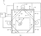
- the various reference signs in Figure 1 respectively represent: 10-inspection system, 12-transverse inlet, 13, 15, 17-source, 18-inspection target, 23, 24, 25, 26, 27, 28-beam, 30-X-ray, 31, 32, 33, 34, 35, 36-detector, 40-processor, 42-internal characteristics of inspection target, 44-scatter radiation.
- the beam emission of each radiation source at different time causes a reduction in an average dose rate of an output radiation from the radiation source of each view.
- the greater the proportion occupied by the beam emission time in the operation cycle the larger the average dose rate of the output radiation will be and the better the image quality will be.
- the beam emission time of each radiation source at most occupies 1/3 of the operation cycle that is, the average dose rate of the output radiation is 1/3 of the single view so that the image quality will be far worse than the single-view system.
- US2016/0025890A1 discloses a multi-view X-ray inspection system having, in one of several embodiments, a three-view configuration with three X-ray sources.
- Each X-ray source rotates and is configured to emit a rotating X-ray pencil beam and at least two detector arrays, where each detector array has multiple non-pixellated detectors such that at least a portion of the non-pixellated detectors are oriented toward both the two X-ray sources.
- the present application provides a multi-view backscatter inspection system and method which aim at effectively reducing the mutual interference between each other during simultaneous beam emission of multiple views, and improving the quality of an inspection image.
- the first aspect of the present application provides a multi-view backscatter inspection system, comprising an inspection passage, at least two inspection units, a control device and a data processing device; wherein, each of the inspection units comprises a radiation source for producing a rotating pencil radiation beam, and a detector array for receiving a backscatter radiation from a detection target irradiated by the radiation beam, the detector array comprising at least two detector modules arranged at different positions and independent of each other; the at least two inspection units are disposed at different circumferential positions of a periphery of the inspection passage respectively to form at least two different views, and arranged so that a radiation beam produced by a radiation source of one of the inspection units is directed to a position beside the detector array of each of the remaining inspection units; the control device is coupled to each of said radiation sources for adjusting a phase difference between the radiation beams of the radiation sources so that an effective detection area of each of the detector arrays is far away from an interference area at any moment, the effective detection area comprises a first position at which the detector array
- the second aspect of the present application provides a multi-view backscatter inspection method of the multi-view backscatter inspection system according to the first aspect of the present application to inspect the inspection target, the multi-view backscatter inspection method comprising:
- the detector array comprises at least two detector modules arranged at different positions and independent of each other, so that the detector array has a position resolution capability. At least two inspection units are arranged so that a radiation beam produced by a radiation source of one of the inspection units is directed to a position beside the detector array of the remaining inspection units. It may prevent interference of a transmission radiation over detection signals from the remaining inspection units when the radiation source penetrates an inspection target. It may adjust a phase difference between radiation beams of the radiation sources, so that an effective detection area of each of the detector arrays at any moment in the inspection process is far away from the interference area.
- the data processing device which calculates an effective detection area and processes a detection signal from a detector module within an effective detection area to form an inspection image of one side located at the inspection unit of the inspection target at a corresponding moment, may favorably suppress the influence of an interference signal, and finally obtain a fine quality of the inspection image.
- a plurality of views in the present application may perform beam emission at the same time, and improve an average dose rate of an output radiation of each view, so that the image quality of the inspection target may be improved.
- azimuth or positional relations indicated by such azimuth terms as “front, rear, up, down, left, right", “transverse, vertical, perpendicular, horizontal” and “top, bottom”, which are usually based on the azimuth or positional relations illustrated by the drawings, are only for facilitating description of the present application and simplifying the description.
- azimuth terms do not indicate or imply that the device or element referred to has to present a particular azimuth or to be constructed and operated in a particular azimuth, so that it cannot be understood as limiting the protection scope of the present application.
- the azimuth terms “within” and “outside” mean the interior and exterior relative to the contour of various members themselves.
- the present application provides a multi-view backscatter inspection system.
- the multi-view backscatter inspection system comprises an inspection passage 30, at least two inspection units, a control device 8 and a data processing device.
- the inspection unit comprises a radiation source and a detector array.
- the radiation source is used for emitting a rotating pencil radiation beam.
- the detector array is used for receiving a backscatter radiation from the inspection target irradiated by the radiation beam from the radiation source.
- the detector array comprises at least two detector modules arranged at different positions and independent of each other, and it is provided so that the detector array has a position resolution capability.
- the amount of detector modules in each detector array may be the same, and may also be different. The greater the amount of detector modules in the detector array, the stronger the position resolution capability of the detector array will be.
- the at least two inspection units are disposed at different circumferential positions of a periphery of the inspection passage 30 to form at least two different views.
- a radiation beam produced by a radiation source of one of the inspection units is directed to a position beside the detector array of the remaining inspection units. It is provided so that a radiation beam produced by a radiation source of any of the inspection unit cannot be directed to the detector array of the remaining inspection units, so that it is possible to prevent interference of a transmission radiation over the remaining inspection units when the radiation source penetrates through the inspection target.
- the at least two inspection units are arranged in staggered manner in an extending direction of the inspection passage 30 such that beam scanning surfaces of the radiation sources are spacedly disposed substantially in parallel to each other, to effectuate that a radiation beam produced by a radiation source of any of the inspection unit is directed to the position beside the detector array of the remaining inspection units.
- the control device 8 is coupled to the radiation source of each of the inspection units.
- the control device 8 adjusts a phase difference between the radiation beams of the radiation sources so that an effective detection area of each of the detector arrays is far away from an interference area at any moment.
- the effective detection area comprises a first position at which the detector array receives the largest backscatter radiation from the same inspection unit as well as an area adjacent to the first position.
- the interference area comprises a second position at which the detector array receives the largest backscatter radiation from the remaining inspection units as well as an area adjacent to the second position.
- the effective detection area changes constantly as a position of the radiation beam changes.
- the interference area also changes constantly as a position of the radiation beam changes.
- the control device 8 may adjust a scanning period, an initial phase and/or a rotation direction of the radiation beam from each of the radiation sources to adjust the phase difference between the radiation beams.
- the effective detection area may be directly determined according to a peak value and a peak position from the detector array; and may also be determined according to a position of the radiation beam.
- the effective detection area when the effective detection area is directly determined according to a peak value and a peak position from the detector array, the position at which the peak value signal is situated as well as the area adjacent to the peak value signal position and with an output signal reaching certain percentage and above of peak value signal (corresponding to an area adjacent to the first position) may serve as an effective detection area.
- the percentage may be between 20% and 70%, for example, may be 20%, 25%, 35%, 50%, 60%, 65%, etc.
- the scatter photon distribution of the radiation beam at different positions are calculated by simulation by means of a computer in advance, the scatter signal distribution on the detector array is calculated according to distribution of scatter photons, and a theoretical effective detection area is determined according to a peak value and a peak position, so as to obtain a theoretical relation between a radiation beam position and an effective detection area.
- an effective detection area is determined according to a radiation beam position, the effective detection area is determined according to a theoretical relation between a radiation beam position and an effective detection area.
- An effective detection area of each of the detector arrays at any moment in the inspection process is far away from the interference area. It may differentiate a detection signal from a detector module corresponding to an effective detection area and a detection signal from a detector module corresponding to the remaining areas, and effectively reduce mutual interference between scatter radiations of the radiation sources.
- the data processing device is coupled to each of the detector arrays to receive a detection signal from each of the detector modules and form an inspection image corresponding to each of the detector arrays at each moment according to the detection signal from each of the detector modules.
- the data processing device calculates an effective detection area of the detector array at the moment, processes a detection signal from a detector module within the effective detection area and forms an inspection image of one side at the detector array of the inspection target 10 at the moment.
- the detection signal from the detector module corresponding to the effective detection area is processed to obtain a fine quality of the inspection image, and effectively reduce the influence of the interference signal over the inspection image.
- a plurality of views in the present application may perform beam emission at the same time, and improve an average dose rate of an output radiation of each view, so that the image quality of the inspection target may be improved.
- the data processing device comprises a data acquisition device and a data processing computer 9.
- the data acquisition device is respectively coupled to the detector array of each of the inspection units and the data processing computer 9, to receive a detection signal from each of the detector modules and transmitting the detection signal to the data processing computer 9.
- the data acquisition device preferably includes a multi-passage data acquisition board 7.
- the data processing computer 9 forms inspection images corresponding to each of the detector arrays at each moment according to a detection signal from each of the detector modules.
- the multi-view backscatter inspection system further comprises a radiation beam position detection device.
- the radiation beam position detection device is coupled to the data processing device.
- the radiation beam position detection device detects a position signal of a radiation beam from a radiation source of each of the inspection units and transmits the position signal to the data processing device.
- the data processing device calculates an effective detection area of the detector array of each of the inspection units according to the position signal.
- the radiation beam position detection device may include two or more sensors in one-to-one correspondence with the radiation sources of two or more inspection units. Each sensor detects a position signal of a radiation beam from a corresponding radiation source.
- the sensor is, for example, an angle sensor that measures a rotation angle of a rotation device of the radiation source.
- the radiation beam position detection device may be directly connected to the data processing device, and may also be connected to the data processing device through the control device 8.
- control device 8 adjusts same scanning cycle and/or rotation direction (for example the rotation directions of the radiation beams of the radiation sources are all in a clockwise direction or a counterclockwise direction), yet different initial phases of the radiation beams of the radiation sources of the inspection units. It is provided so that the adjusting process is simpler.
- the multi-view backscatter inspection system may comprise two inspection units.
- the multi-view backscatter inspection system may include a first inspection unit and a second inspection unit respectively provided at two opposite sides of the inspection passage 30.
- a first end of the first inspection unit and a first end of the second inspection unit form a common first end and a second end of the first inspection unit and a second end of the second inspection unit form a common second end.
- the control device 8 causes the scanning of the radiation beam from the radiation source of the first inspection unit from the first end of the first inspection unit to the second end of the first inspection unit, and simultaneously causes the scanning of the radiation beam from the radiation source of the second inspection unit from the second end of the second inspection unit to the first end of the second inspection unit.
- both the first inspection unit and the second inspection unit are disposed in a longitudinal direction.
- the upper end is the common second end. It is provided so that the effective detection area of each of the detector arrays is separated from the interference area of corresponding the detector array, and the first inspection unit and the second inspection unit opposite to each other do not interfere with each other.
- the multi-view backscatter inspection system may also comprise a first inspection unit and a second inspection unit adjacently provided in a circumferential direction of the inspection passage 30, and the control device 8 causes the scanning of the radiation beam from the radiation source of the first inspection unit starting from one end of the first inspection unit far away from the second inspection unit to another end of the first inspection unit proximate to the second inspection unit, and simultaneously causes the scanning of the radiation beam from the radiation source of the second inspection unit starting from one end of the second inspection unit proximate to the first inspection unit to another end of the second inspection unit far away from the first inspection unit.
- the effective detection area of each of the detector arrays is separated from the interference area of corresponding the detector array.
- the multi-view backscatter inspection system may include three or more inspection units.
- the multi-view backscatter inspection system further comprises a third inspection unit adjacent to the first inspection unit and the second inspection unit, the third inspection unit is disposed at the common second end, and the control device 8 simultaneously causes the scanning of the radiation beam from the radiation source of the third inspection unit from one end of the third inspection unit proximate to the first inspection unit to another end of the third inspection unit proximate to the second inspection unit.
- the effective detection area of each of the detector arrays in the three inspection units is separated from the interference area of corresponding the detector array.
- the embodiments of the present application further provide a multi-view backscatter inspection method.
- the multi-view backscatter inspection method inspects the inspection target 10 using the aforementioned multi-view backscatter inspection system.
- the multi-view backscatter inspection method comprises:
- the multi-view backscatter inspection method further comprises: detecting a position signal of a radiation beam from a radiation source of each of the inspection units, and calculating an effective detection area of the detector array of each of the inspection units according to the position signal.
- the multi-view backscatter inspection method comprises adjusting the same scanning cycle and/or rotation direction, yet different initial phases of the radiation beams of the detectors of each of the inspection units.
- the multi-view backscatter inspection method preferably comprises: causing the scanning of the radiation beam from the radiation source of the first inspection unit from the first end of the first inspection unit to the second end of the first inspection unit, and at the same time causing the scanning of the radiation beam from the radiation source of the second inspection unit from the second end of the second inspection unit to the first end of the second inspection unit.
- the multi-view backscatter inspection method preferably further comprises: simultaneously causing the scanning of the radiation beam from the radiation source of the third inspection unit from one end of the third inspection unit proximate to the first inspection unit to another end of the third inspection unit proximate to the second inspection unit.
- the multi-view backscatter inspection method preferably comprises: causing the scanning of the radiation beam from the radiation source of the first inspection unit starting from one end of the first inspection unit far away from the second inspection unit to another end of the first inspection unit proximate to the second inspection unit, and at the same time causing the scanning of the radiation beam from the radiation source of the second inspection unit starting from one end of the second inspection unit proximate to the first inspection unit to another end of the second inspection unit far away from the first inspection unit.
- the multi-view backscatter inspection method has the same advantages as the aforementioned multi-view backscatter inspection system.
- the multi-view backscatter inspection system of the embodiment is a three-view backscatter inspection system.
- the three-view backscatter inspection system has three inspection units in total, respectively a left inspection unit, a top inspection unit and a right inspection unit. Each inspection unit forms an inspection view.
- the three-view backscatter inspection system further comprises a control device 8, a radiation beam position detection device, and a data processing device.
- the left inspection unit which is located on a left side of the inspection passage 30 to form a left inspection face includes a radiation source 2 and a detector array 1.
- the top inspection unit which is located at the top of the inspection passage 30 to form a top inspection face includes a radiation source 4 and a detector array 3.
- the right inspection unit which is located on a right side of the inspection passage 30 to form a right inspection face includes a radiation source 6 and a detector array 5.
- the radiation source 2, the radiation source 4 and the radiation source 6 which are all X-ray sources for producing a rotary pencil beam, may produce X-ray beams in a pencil shape periodically changing in spatial position.
- the rotary X-ray sources in a pencil beam described in the Chinese Patent Application No. CN1947001A and the American Patents US8861684B2 and US6434219B1 may serve as the radiation source of the present application.
- the detector array 1, the detector array 3 and the detector array 5 respectively include at least two detector modules arranged at different positions and independent of each other.
- Each of the detector modules is independent of each other, so that each of the detector modules of the present embodiment has a resolution capability.
- the radiation beam from the radiation source 2 scans to form a left-view beam scanning surface 21; the radiation beam from the radiation source 4 scans to form a top-view beam scanning surface 22; the radiation beam from the radiation source 6 scans to form a right-view beam scanning surface 23.
- the left view beam scanning surface 21, the top view beam scanning surface 22, and the right view beam scanning surface 23 are not coplanar with each other and are spaced apart from each other by certain distance substantially in parallel to each other. The spaced distance allows that the beam produced by the radiation source 2 cannot be directed to the detector array 3 and the detector array 5, the beam produced by the radiation source 4 cannot be directed to the detector array 1 and the detector array 5, and the beam produced by the radiation source 6 cannot be directed to the detector array 1 and the detector array 3.
- the three-view backscatter inspection system of the present embodiment effectuates that a radiation beam produced by the radiation source of any of the inspection units is directed to the outside of the detector array of the remaining inspection units.
- the interference of the transmission light of any of the radiation sources over other inspection units may be eliminated.
- the data processing device comprises a data acquisition device and a data processing computer 9.
- the data acquisition device includes a multi-passage data acquisition board 7.
- the multi-passage data acquisition board 7 is respectively coupled to the control device 8 and the data processing computer 9.
- the amount of the multi-passage data acquisition board 7 may be one or more, depending on the amount of passages of the multi-passage data acquisition board 7 and the amount of the detector modules.
- each detector module of the detector arrays of each inspection unit is respectively accessed to a plurality of passages of the multi-passage data acquisition board 7 so that the multi-passage data acquisition board 7 can acquire the detection signals from each detector module and transfer the detection signals to the data processing computer 9.
- the control device 8 which is respectively coupled to the radiation source 2, the radiation source 4 and the radiation source 6, may send a control signal to each of the radiation sources.
- the scanning cycles and rotation directions of the radiation beams of the radiation sources are the same, while the initial phases of the radiation beams of the radiation sources adjusted by the control device 8 are different.
- the rotation directions of each of the radiation sources are in a counterclockwise rotation.
- the radiation beam position detection device includes sensors respectively provided on the radiation source 2, the radiation source 4 and the radiation source 6 and coupled to the data processing device.
- the radiation beam position detection device acquires a position signal of the radiation beam from the corresponding radiation source.
- the sensor first sends a position signal to the control device 8 which then sends each position signal to the data processing computer 9 through the multi-passage data acquisition board 7.
- the multi-passage data acquisition board 7 simultaneously acquires the detection signals from each of the detector modules and the position signals of the radiation beam from each of the radiation sources detected by each of the sensors, and sends each of the detection signals and each of the position signals to the data processing computer 9.
- the data processing computer 9 calculates an effective detection area of each detector array at the moment according to a position signal of the radiation at each moment, and forms an inspection image corresponding to the inspection target 10 according to a detection signal from each detector module within the effective detection area, so as to reduce the interference of scatter radiation from other inspection units.
- the mutual interference between multiple view of the multi-view backscatter inspection system is mainly divided into two aspects: the first is the interference of the transmission radiation over the opposite detector array after the radiation beam passes through the inspection target 10, for example the interference of the radiation source 2 over the detector array 5; the second is the interference of the radiation beam (including backscatter radiation and forward scatter radiation) produced by scattering the radiation beam via the inspection target 10 over the detector arrays of the remaining inspection units, for example the interference of the radiation source 2 over the detector array 3.
- the present embodiment may effectively eliminate mutual interference produced by the transmission radiation by spacing the beam scanning surfaces of the radiation sources by certain distance.
- the interference produced by the scatter radiation may separate an effective detection area and an interference area of each detector array at any moment by adjusting a phase difference between the radiation beams of the radiation sources of the inspection units, and form an inspection image of the detection target according to a detection signal from the detection module within an effective detection area of the detector array, so as to effectively reduce the interference produced by the scatter radiation.
- the radiation beams produced by the radiation source 2, the radiation source 4 and the radiation source 6 are all in counterclockwise rotation.
- the control device 8 causes the same scanning cycle of the radiation beams of the three radiation sources.
- the radiation beam from each radiation source may sweep the surface of the inspection target 10 three times.
- the control device 8 accurately adjusts the initial phase of the radiation beams of each of the radiation sources.
- the radiation beam from the radiation source 2 when initialized is projected to the left lowermost of the inspection target 10
- the radiation beam from the radiation source 4 when initialized is projected to the left uppermost of the inspection target 10
- the radiation beam from the radiation source 6 when initialized is projected to the right uppermost of the inspection target 10. Since each radiation source is in counterclockwise rotation, the position of the radiation beam from each radiation source is shown in the picture b2 of Figure 4 after a 1/6 rotation cycle, and the position of the radiation beam from each radiation source is shown in the picture c2 of Figure 4 after a further 1/6 rotation cycle.
- the position at which the radiation beam is projected on the inspection target 10 is called as a detection point.
- the detection points produced from the radiation source 2 that are scattered to different positions of the detector array 1 have different photon fluxes.
- a distribution curve may be formed according to different positions on the detector array as well as the corresponding photon fluxes.
- the picture a1 (corresponding to the picture a2), the picture b1 (corresponding to the picture b2) and the picture c1 (corresponding to the picture c2) of Figure 4 show a distribution curve of the scatter photon fluxes of the detector array 1 corresponding to different moments.
- an effective detection area of a detector array may be provided according to a position of the detection point. It may be considers that only a photon within an effective detection area is a photon scattered from a detection point of the radiation source 2.
- the backscatter radiation of the detection point of the radiation source 4 may be projected into the detector array to form an interference area.
- a notable interference area may be formed at an upper portion of the detector array 1, as shown in the picture a1 of Figure 4 .
- an interference area of the detector array 1 due to the radiation source 4 is separated from an effective detection area of the detector array 1, and at the same time, an interference area of the detector array 5 due to the radiation source 4 is also separated from the effective detection area of the detector array 5.
- the interference of the scatter radiation of other inspection units may be effectively reduced by forming an inspection image using a detection signal from a detector module corresponding to an effective detection area.
- the beam scanning surfaces of various views in the embodiments of the present application are away from each other by certain distance, and a phase different between the radiation beams from the radiation sources is adjusted, and the detection signals of an effective detection area and the remaining detection areas are differentiated, so that the radiation sources of the views even when performing simultaneous beam emission, may also effectively reduce the mutual interference between multiple views.
- each of the views is capable of performing beam emission at the same time, and improving an average dose rate of an output radiation of each view, so that the image quality may be improved.
Landscapes
- Physics & Mathematics (AREA)
- Chemical & Material Sciences (AREA)
- Life Sciences & Earth Sciences (AREA)
- General Physics & Mathematics (AREA)
- Biochemistry (AREA)
- Analytical Chemistry (AREA)
- Health & Medical Sciences (AREA)
- General Health & Medical Sciences (AREA)
- Immunology (AREA)
- Pathology (AREA)
- Crystallography & Structural Chemistry (AREA)
- High Energy & Nuclear Physics (AREA)
- General Life Sciences & Earth Sciences (AREA)
- Geophysics (AREA)
- Analysing Materials By The Use Of Radiation (AREA)
Priority Applications (1)
| Application Number | Priority Date | Filing Date | Title |
|---|---|---|---|
| PL18156264T PL3364176T3 (pl) | 2017-02-17 | 2018-02-12 | Układ do wielowidokowej kontroli rozproszeniem wstecznym oraz sposób wielowidokowej kontroli rozproszeniem wstecznym |
Applications Claiming Priority (1)
| Application Number | Priority Date | Filing Date | Title |
|---|---|---|---|
| CN201710084834.9A CN106841256B (zh) | 2017-02-17 | 2017-02-17 | 多视角背散射检查系统和多视角背散射检查方法 |
Publications (2)
| Publication Number | Publication Date |
|---|---|
| EP3364176A1 EP3364176A1 (en) | 2018-08-22 |
| EP3364176B1 true EP3364176B1 (en) | 2021-05-19 |
Family
ID=59129027
Family Applications (1)
| Application Number | Title | Priority Date | Filing Date |
|---|---|---|---|
| EP18156264.6A Active EP3364176B1 (en) | 2017-02-17 | 2018-02-12 | Multi-view backscatter inspection system and multi-view backscatter inspection method |
Country Status (4)
| Country | Link |
|---|---|
| EP (1) | EP3364176B1 (zh) |
| CN (1) | CN106841256B (zh) |
| AU (1) | AU2018200809B2 (zh) |
| PL (1) | PL3364176T3 (zh) |
Families Citing this family (15)
| Publication number | Priority date | Publication date | Assignee | Title |
|---|---|---|---|---|
| CN107300721B (zh) * | 2017-08-10 | 2023-12-15 | 苏州曼德克光电有限公司 | 一种基于射线的载货车辆三维成像检测系统 |
| CN108121014A (zh) * | 2017-12-07 | 2018-06-05 | 公安部第三研究所 | 立体视角散射阵列探测系统及方法 |
| CN108426899A (zh) * | 2018-05-10 | 2018-08-21 | 同方威视技术股份有限公司 | 复合检查设备和复合检查方法 |
| CN108594317A (zh) * | 2018-05-10 | 2018-09-28 | 同方威视技术股份有限公司 | 双通道背散射检测设备 |
| CN109142404A (zh) * | 2018-11-01 | 2019-01-04 | 同方威视技术股份有限公司 | 背散射成像系统、扫描检查系统和背散射图像成像方法 |
| CN109375250B (zh) * | 2018-12-24 | 2024-05-14 | 同方威视技术股份有限公司 | 探测器系统和辐射成像装置 |
| CN109613031A (zh) * | 2019-01-04 | 2019-04-12 | 清华大学 | 背散射检查系统和背散射检查方法 |
| CN109765250B (zh) * | 2019-01-31 | 2023-02-03 | 南京森林警察学院 | 一种高效毒品ct扫描检测装置 |
| CN110609312B (zh) * | 2019-09-04 | 2021-04-20 | 中国疾病预防控制中心辐射防护与核安全医学所 | 一种粮食放射性检测工作台及其作业方法 |
| CN111142167A (zh) * | 2019-11-06 | 2020-05-12 | 中国辐射防护研究院 | 一种利用钋-210法探测煤自燃火源位置的方法 |
| CN113609971A (zh) * | 2021-08-04 | 2021-11-05 | 广州威拓电子科技有限公司 | 微地震观测设备的检查方法、装置、设备及存储介质 |
| CN115931937A (zh) * | 2021-08-17 | 2023-04-07 | 同方威视技术股份有限公司 | 背散射检查设备 |
| CN114152994A (zh) * | 2021-12-31 | 2022-03-08 | 同方威视科技(北京)有限公司 | 安检设备、安检系统及安检方法 |
| CN114714375B (zh) * | 2022-04-28 | 2022-10-28 | 北京诚志北分机电技术有限公司 | 一种便携式背散射x光安检机器人 |
| CN115508392A (zh) * | 2022-10-28 | 2022-12-23 | 同方威视技术股份有限公司 | 扫描成像设备和扫描成像方法 |
Family Cites Families (10)
| Publication number | Priority date | Publication date | Assignee | Title |
|---|---|---|---|---|
| US6094472A (en) * | 1998-04-14 | 2000-07-25 | Rapiscan Security Products, Inc. | X-ray backscatter imaging system including moving body tracking assembly |
| US6434219B1 (en) | 2000-07-24 | 2002-08-13 | American Science And Engineering, Inc. | Chopper wheel with two axes of rotation |
| US7400701B1 (en) | 2004-04-09 | 2008-07-15 | American Science And Engineering, Inc. | Backscatter inspection portal |
| PL2755557T3 (pl) | 2011-09-12 | 2023-07-17 | American Science & Engineering, Inc. | Mająca przesunięcie do przodu i zmienne obręcz do skanowania wiązką |
| EP3358597A1 (en) * | 2012-02-03 | 2018-08-08 | Rapiscan Systems, Inc. | Combined scatter and transmission multi-view imaging system |
| CN104101910A (zh) * | 2014-07-04 | 2014-10-15 | 清华大学 | 基于分布式辐射源的x射线背散射通道式车辆安检系统和方法 |
| CN204129240U (zh) * | 2014-07-04 | 2015-01-28 | 清华大学 | X射线背散射通道式安检系统 |
| CN104483711B (zh) * | 2014-12-17 | 2020-02-21 | 同方威视技术股份有限公司 | 基于分布式光源的辐射成像系统 |
| CN105784741A (zh) * | 2015-07-10 | 2016-07-20 | 公安部第研究所 | 一种多视角x射线安全检查装置 |
| CN206573504U (zh) * | 2017-02-17 | 2017-10-20 | 清华大学 | 多视角背散射检查系统 |
-
2017
- 2017-02-17 CN CN201710084834.9A patent/CN106841256B/zh active Active
-
2018
- 2018-02-02 AU AU2018200809A patent/AU2018200809B2/en active Active
- 2018-02-12 PL PL18156264T patent/PL3364176T3/pl unknown
- 2018-02-12 EP EP18156264.6A patent/EP3364176B1/en active Active
Non-Patent Citations (1)
| Title |
|---|
| None * |
Also Published As
| Publication number | Publication date |
|---|---|
| CN106841256A (zh) | 2017-06-13 |
| CN106841256B (zh) | 2023-11-21 |
| AU2018200809B2 (en) | 2019-02-21 |
| EP3364176A1 (en) | 2018-08-22 |
| PL3364176T3 (pl) | 2021-09-27 |
| AU2018200809A1 (en) | 2018-09-06 |
Similar Documents
| Publication | Publication Date | Title |
|---|---|---|
| EP3364176B1 (en) | Multi-view backscatter inspection system and multi-view backscatter inspection method | |
| US7724869B2 (en) | Detector array and device using the same | |
| CN104254769B (zh) | 高速安全检查系统 | |
| EP2963455B1 (en) | X-ray backscattering safety inspection system having distributed x-ray source and method using the same | |
| EP2385390B1 (en) | System and method for estimating position and direction | |
| EP3213119B1 (en) | Pet detector timing calibration | |
| KR20180041763A (ko) | 선형 적응적 전자기 x-선 스캐닝을 이용한 후방산란 특성화 | |
| CN105627926A (zh) | 四像机组平面阵列特征点三维测量系统及测量方法 | |
| KR102033233B1 (ko) | 멀티 모달 검출 시스템 및 방법 | |
| CN102639059A (zh) | X射线成像装置和x射线成像方法 | |
| JP2007127617A (ja) | 高速中性子及び連続エネルギー・スペクトルx線により材料識別する方法及びその装置 | |
| TR201901095T4 (tr) | Mobil geri saçılım görüntüleme güvenlik incelemesi aparatı ve yöntemi. | |
| RU2014105575A (ru) | Динамическая коллимация | |
| EP3182175B1 (en) | X-ray diffraction detection system and method | |
| WO2011097386A1 (en) | Multiple plane multi-inverse fan-beam detection systems and method for using the same | |
| CN104062688A (zh) | 基于分布式辐射源的x射线背散射通道式车辆安检系统和方法 | |
| WO2010059784A2 (en) | Methods and system for calibrating and correcting a detection system | |
| US9279892B2 (en) | Systems and methods for scintillators having polished and roughened surfaces | |
| WO2023125409A1 (zh) | 安检设备、安检系统及安检方法 | |
| JP2013101101A5 (zh) | ||
| CN216595556U (zh) | 安检设备及安检系统 | |
| CN104792805B (zh) | 一种透射探测器和插值数据计算方法 | |
| CN108827984A (zh) | 一种交错式照射野可调准直器 | |
| US20080219404A1 (en) | Method and Apparatus to Facilitate Formation of a Two-Dimensional Image Using X-Ray Fan Beam Scatter | |
| KR20220080359A (ko) | 라이다 장치 |
Legal Events
| Date | Code | Title | Description |
|---|---|---|---|
| PUAI | Public reference made under article 153(3) epc to a published international application that has entered the european phase |
Free format text: ORIGINAL CODE: 0009012 |
|
| STAA | Information on the status of an ep patent application or granted ep patent |
Free format text: STATUS: THE APPLICATION HAS BEEN PUBLISHED |
|
| AK | Designated contracting states |
Kind code of ref document: A1 Designated state(s): AL AT BE BG CH CY CZ DE DK EE ES FI FR GB GR HR HU IE IS IT LI LT LU LV MC MK MT NL NO PL PT RO RS SE SI SK SM TR |
|
| AX | Request for extension of the european patent |
Extension state: BA ME |
|
| STAA | Information on the status of an ep patent application or granted ep patent |
Free format text: STATUS: REQUEST FOR EXAMINATION WAS MADE |
|
| 17P | Request for examination filed |
Effective date: 20190221 |
|
| RBV | Designated contracting states (corrected) |
Designated state(s): AL AT BE BG CH CY CZ DE DK EE ES FI FR GB GR HR HU IE IS IT LI LT LU LV MC MK MT NL NO PL PT RO RS SE SI SK SM TR |
|
| GRAP | Despatch of communication of intention to grant a patent |
Free format text: ORIGINAL CODE: EPIDOSNIGR1 |
|
| STAA | Information on the status of an ep patent application or granted ep patent |
Free format text: STATUS: GRANT OF PATENT IS INTENDED |
|
| INTG | Intention to grant announced |
Effective date: 20201210 |
|
| RIN1 | Information on inventor provided before grant (corrected) |
Inventor name: LI, YUANJING Inventor name: LI, YULAN Inventor name: CHEN, ZHIQIANG Inventor name: LIU, LEI Inventor name: CHI, HAOJIE Inventor name: ZONG, CHUNGUANG Inventor name: ZHANG, LI Inventor name: LI, JIANMIN Inventor name: YU, HAO |
|
| GRAS | Grant fee paid |
Free format text: ORIGINAL CODE: EPIDOSNIGR3 |
|
| GRAA | (expected) grant |
Free format text: ORIGINAL CODE: 0009210 |
|
| STAA | Information on the status of an ep patent application or granted ep patent |
Free format text: STATUS: THE PATENT HAS BEEN GRANTED |
|
| AK | Designated contracting states |
Kind code of ref document: B1 Designated state(s): AL AT BE BG CH CY CZ DE DK EE ES FI FR GB GR HR HU IE IS IT LI LT LU LV MC MK MT NL NO PL PT RO RS SE SI SK SM TR |
|
| REG | Reference to a national code |
Ref country code: GB Ref legal event code: FG4D |
|
| REG | Reference to a national code |
Ref country code: CH Ref legal event code: EP |
|
| REG | Reference to a national code |
Ref country code: DE Ref legal event code: R096 Ref document number: 602018017146 Country of ref document: DE |
|
| REG | Reference to a national code |
Ref country code: AT Ref legal event code: REF Ref document number: 1394477 Country of ref document: AT Kind code of ref document: T Effective date: 20210615 |
|
| REG | Reference to a national code |
Ref country code: IE Ref legal event code: FG4D |
|
| REG | Reference to a national code |
Ref country code: LT Ref legal event code: MG9D |
|
| REG | Reference to a national code |
Ref country code: AT Ref legal event code: MK05 Ref document number: 1394477 Country of ref document: AT Kind code of ref document: T Effective date: 20210519 |
|
| REG | Reference to a national code |
Ref country code: NL Ref legal event code: MP Effective date: 20210519 |
|
| PG25 | Lapsed in a contracting state [announced via postgrant information from national office to epo] |
Ref country code: FI Free format text: LAPSE BECAUSE OF FAILURE TO SUBMIT A TRANSLATION OF THE DESCRIPTION OR TO PAY THE FEE WITHIN THE PRESCRIBED TIME-LIMIT Effective date: 20210519 Ref country code: LT Free format text: LAPSE BECAUSE OF FAILURE TO SUBMIT A TRANSLATION OF THE DESCRIPTION OR TO PAY THE FEE WITHIN THE PRESCRIBED TIME-LIMIT Effective date: 20210519 Ref country code: HR Free format text: LAPSE BECAUSE OF FAILURE TO SUBMIT A TRANSLATION OF THE DESCRIPTION OR TO PAY THE FEE WITHIN THE PRESCRIBED TIME-LIMIT Effective date: 20210519 Ref country code: AT Free format text: LAPSE BECAUSE OF FAILURE TO SUBMIT A TRANSLATION OF THE DESCRIPTION OR TO PAY THE FEE WITHIN THE PRESCRIBED TIME-LIMIT Effective date: 20210519 Ref country code: BG Free format text: LAPSE BECAUSE OF FAILURE TO SUBMIT A TRANSLATION OF THE DESCRIPTION OR TO PAY THE FEE WITHIN THE PRESCRIBED TIME-LIMIT Effective date: 20210819 |
|
| PG25 | Lapsed in a contracting state [announced via postgrant information from national office to epo] |
Ref country code: IS Free format text: LAPSE BECAUSE OF FAILURE TO SUBMIT A TRANSLATION OF THE DESCRIPTION OR TO PAY THE FEE WITHIN THE PRESCRIBED TIME-LIMIT Effective date: 20210919 Ref country code: GR Free format text: LAPSE BECAUSE OF FAILURE TO SUBMIT A TRANSLATION OF THE DESCRIPTION OR TO PAY THE FEE WITHIN THE PRESCRIBED TIME-LIMIT Effective date: 20210820 Ref country code: NO Free format text: LAPSE BECAUSE OF FAILURE TO SUBMIT A TRANSLATION OF THE DESCRIPTION OR TO PAY THE FEE WITHIN THE PRESCRIBED TIME-LIMIT Effective date: 20210819 Ref country code: PT Free format text: LAPSE BECAUSE OF FAILURE TO SUBMIT A TRANSLATION OF THE DESCRIPTION OR TO PAY THE FEE WITHIN THE PRESCRIBED TIME-LIMIT Effective date: 20210920 Ref country code: LV Free format text: LAPSE BECAUSE OF FAILURE TO SUBMIT A TRANSLATION OF THE DESCRIPTION OR TO PAY THE FEE WITHIN THE PRESCRIBED TIME-LIMIT Effective date: 20210519 Ref country code: SE Free format text: LAPSE BECAUSE OF FAILURE TO SUBMIT A TRANSLATION OF THE DESCRIPTION OR TO PAY THE FEE WITHIN THE PRESCRIBED TIME-LIMIT Effective date: 20210519 Ref country code: RS Free format text: LAPSE BECAUSE OF FAILURE TO SUBMIT A TRANSLATION OF THE DESCRIPTION OR TO PAY THE FEE WITHIN THE PRESCRIBED TIME-LIMIT Effective date: 20210519 |
|
| PG25 | Lapsed in a contracting state [announced via postgrant information from national office to epo] |
Ref country code: NL Free format text: LAPSE BECAUSE OF FAILURE TO SUBMIT A TRANSLATION OF THE DESCRIPTION OR TO PAY THE FEE WITHIN THE PRESCRIBED TIME-LIMIT Effective date: 20210519 |
|
| PG25 | Lapsed in a contracting state [announced via postgrant information from national office to epo] |
Ref country code: RO Free format text: LAPSE BECAUSE OF FAILURE TO SUBMIT A TRANSLATION OF THE DESCRIPTION OR TO PAY THE FEE WITHIN THE PRESCRIBED TIME-LIMIT Effective date: 20210519 Ref country code: CZ Free format text: LAPSE BECAUSE OF FAILURE TO SUBMIT A TRANSLATION OF THE DESCRIPTION OR TO PAY THE FEE WITHIN THE PRESCRIBED TIME-LIMIT Effective date: 20210519 Ref country code: DK Free format text: LAPSE BECAUSE OF FAILURE TO SUBMIT A TRANSLATION OF THE DESCRIPTION OR TO PAY THE FEE WITHIN THE PRESCRIBED TIME-LIMIT Effective date: 20210519 Ref country code: SK Free format text: LAPSE BECAUSE OF FAILURE TO SUBMIT A TRANSLATION OF THE DESCRIPTION OR TO PAY THE FEE WITHIN THE PRESCRIBED TIME-LIMIT Effective date: 20210519 Ref country code: SM Free format text: LAPSE BECAUSE OF FAILURE TO SUBMIT A TRANSLATION OF THE DESCRIPTION OR TO PAY THE FEE WITHIN THE PRESCRIBED TIME-LIMIT Effective date: 20210519 Ref country code: EE Free format text: LAPSE BECAUSE OF FAILURE TO SUBMIT A TRANSLATION OF THE DESCRIPTION OR TO PAY THE FEE WITHIN THE PRESCRIBED TIME-LIMIT Effective date: 20210519 Ref country code: ES Free format text: LAPSE BECAUSE OF FAILURE TO SUBMIT A TRANSLATION OF THE DESCRIPTION OR TO PAY THE FEE WITHIN THE PRESCRIBED TIME-LIMIT Effective date: 20210519 |
|
| REG | Reference to a national code |
Ref country code: DE Ref legal event code: R097 Ref document number: 602018017146 Country of ref document: DE |
|
| PLBE | No opposition filed within time limit |
Free format text: ORIGINAL CODE: 0009261 |
|
| STAA | Information on the status of an ep patent application or granted ep patent |
Free format text: STATUS: NO OPPOSITION FILED WITHIN TIME LIMIT |
|
| 26N | No opposition filed |
Effective date: 20220222 |
|
| PG25 | Lapsed in a contracting state [announced via postgrant information from national office to epo] |
Ref country code: IS Free format text: LAPSE BECAUSE OF FAILURE TO SUBMIT A TRANSLATION OF THE DESCRIPTION OR TO PAY THE FEE WITHIN THE PRESCRIBED TIME-LIMIT Effective date: 20210919 Ref country code: AL Free format text: LAPSE BECAUSE OF FAILURE TO SUBMIT A TRANSLATION OF THE DESCRIPTION OR TO PAY THE FEE WITHIN THE PRESCRIBED TIME-LIMIT Effective date: 20210519 |
|
| PG25 | Lapsed in a contracting state [announced via postgrant information from national office to epo] |
Ref country code: IT Free format text: LAPSE BECAUSE OF FAILURE TO SUBMIT A TRANSLATION OF THE DESCRIPTION OR TO PAY THE FEE WITHIN THE PRESCRIBED TIME-LIMIT Effective date: 20210519 |
|
| REG | Reference to a national code |
Ref country code: DE Ref legal event code: R119 Ref document number: 602018017146 Country of ref document: DE |
|
| PG25 | Lapsed in a contracting state [announced via postgrant information from national office to epo] |
Ref country code: MC Free format text: LAPSE BECAUSE OF FAILURE TO SUBMIT A TRANSLATION OF THE DESCRIPTION OR TO PAY THE FEE WITHIN THE PRESCRIBED TIME-LIMIT Effective date: 20210519 |
|
| REG | Reference to a national code |
Ref country code: CH Ref legal event code: PL |
|
| REG | Reference to a national code |
Ref country code: BE Ref legal event code: MM Effective date: 20220228 |
|
| PG25 | Lapsed in a contracting state [announced via postgrant information from national office to epo] |
Ref country code: LU Free format text: LAPSE BECAUSE OF NON-PAYMENT OF DUE FEES Effective date: 20220212 |
|
| PG25 | Lapsed in a contracting state [announced via postgrant information from national office to epo] |
Ref country code: LI Free format text: LAPSE BECAUSE OF NON-PAYMENT OF DUE FEES Effective date: 20220228 Ref country code: IE Free format text: LAPSE BECAUSE OF NON-PAYMENT OF DUE FEES Effective date: 20220212 Ref country code: DE Free format text: LAPSE BECAUSE OF NON-PAYMENT OF DUE FEES Effective date: 20220901 Ref country code: CH Free format text: LAPSE BECAUSE OF NON-PAYMENT OF DUE FEES Effective date: 20220228 |
|
| PG25 | Lapsed in a contracting state [announced via postgrant information from national office to epo] |
Ref country code: BE Free format text: LAPSE BECAUSE OF NON-PAYMENT OF DUE FEES Effective date: 20220228 |
|
| PGFP | Annual fee paid to national office [announced via postgrant information from national office to epo] |
Ref country code: FR Payment date: 20230110 Year of fee payment: 6 |
|
| PGFP | Annual fee paid to national office [announced via postgrant information from national office to epo] |
Ref country code: PL Payment date: 20230117 Year of fee payment: 6 |
|
| P01 | Opt-out of the competence of the unified patent court (upc) registered |
Effective date: 20230528 |
|
| PG25 | Lapsed in a contracting state [announced via postgrant information from national office to epo] |
Ref country code: HU Free format text: LAPSE BECAUSE OF FAILURE TO SUBMIT A TRANSLATION OF THE DESCRIPTION OR TO PAY THE FEE WITHIN THE PRESCRIBED TIME-LIMIT; INVALID AB INITIO Effective date: 20180212 |
|
| PG25 | Lapsed in a contracting state [announced via postgrant information from national office to epo] |
Ref country code: MK Free format text: LAPSE BECAUSE OF FAILURE TO SUBMIT A TRANSLATION OF THE DESCRIPTION OR TO PAY THE FEE WITHIN THE PRESCRIBED TIME-LIMIT Effective date: 20210519 Ref country code: CY Free format text: LAPSE BECAUSE OF FAILURE TO SUBMIT A TRANSLATION OF THE DESCRIPTION OR TO PAY THE FEE WITHIN THE PRESCRIBED TIME-LIMIT Effective date: 20210519 |
|
| PGFP | Annual fee paid to national office [announced via postgrant information from national office to epo] |
Ref country code: GB Payment date: 20240118 Year of fee payment: 7 |