EP3364140A1 - Cooling device and cooling system - Google Patents
Cooling device and cooling system Download PDFInfo
- Publication number
- EP3364140A1 EP3364140A1 EP16855126.5A EP16855126A EP3364140A1 EP 3364140 A1 EP3364140 A1 EP 3364140A1 EP 16855126 A EP16855126 A EP 16855126A EP 3364140 A1 EP3364140 A1 EP 3364140A1
- Authority
- EP
- European Patent Office
- Prior art keywords
- refrigerant
- casing
- refrigerant relay
- example embodiment
- relay
- Prior art date
- Legal status (The legal status is an assumption and is not a legal conclusion. Google has not performed a legal analysis and makes no representation as to the accuracy of the status listed.)
- Granted
Links
Images







Classifications
-
- F—MECHANICAL ENGINEERING; LIGHTING; HEATING; WEAPONS; BLASTING
- F28—HEAT EXCHANGE IN GENERAL
- F28D—HEAT-EXCHANGE APPARATUS, NOT PROVIDED FOR IN ANOTHER SUBCLASS, IN WHICH THE HEAT-EXCHANGE MEDIA DO NOT COME INTO DIRECT CONTACT
- F28D15/00—Heat-exchange apparatus with the intermediate heat-transfer medium in closed tubes passing into or through the conduit walls ; Heat-exchange apparatus employing intermediate heat-transfer medium or bodies
- F28D15/02—Heat-exchange apparatus with the intermediate heat-transfer medium in closed tubes passing into or through the conduit walls ; Heat-exchange apparatus employing intermediate heat-transfer medium or bodies in which the medium condenses and evaporates, e.g. heat pipes
- F28D15/0266—Heat-exchange apparatus with the intermediate heat-transfer medium in closed tubes passing into or through the conduit walls ; Heat-exchange apparatus employing intermediate heat-transfer medium or bodies in which the medium condenses and evaporates, e.g. heat pipes with separate evaporating and condensing chambers connected by at least one conduit; Loop-type heat pipes; with multiple or common evaporating or condensing chambers
-
- F—MECHANICAL ENGINEERING; LIGHTING; HEATING; WEAPONS; BLASTING
- F28—HEAT EXCHANGE IN GENERAL
- F28D—HEAT-EXCHANGE APPARATUS, NOT PROVIDED FOR IN ANOTHER SUBCLASS, IN WHICH THE HEAT-EXCHANGE MEDIA DO NOT COME INTO DIRECT CONTACT
- F28D15/00—Heat-exchange apparatus with the intermediate heat-transfer medium in closed tubes passing into or through the conduit walls ; Heat-exchange apparatus employing intermediate heat-transfer medium or bodies
- F28D15/02—Heat-exchange apparatus with the intermediate heat-transfer medium in closed tubes passing into or through the conduit walls ; Heat-exchange apparatus employing intermediate heat-transfer medium or bodies in which the medium condenses and evaporates, e.g. heat pipes
- F28D15/0241—Heat-exchange apparatus with the intermediate heat-transfer medium in closed tubes passing into or through the conduit walls ; Heat-exchange apparatus employing intermediate heat-transfer medium or bodies in which the medium condenses and evaporates, e.g. heat pipes the tubes being flexible
-
- F—MECHANICAL ENGINEERING; LIGHTING; HEATING; WEAPONS; BLASTING
- F28—HEAT EXCHANGE IN GENERAL
- F28D—HEAT-EXCHANGE APPARATUS, NOT PROVIDED FOR IN ANOTHER SUBCLASS, IN WHICH THE HEAT-EXCHANGE MEDIA DO NOT COME INTO DIRECT CONTACT
- F28D15/00—Heat-exchange apparatus with the intermediate heat-transfer medium in closed tubes passing into or through the conduit walls ; Heat-exchange apparatus employing intermediate heat-transfer medium or bodies
- F28D15/02—Heat-exchange apparatus with the intermediate heat-transfer medium in closed tubes passing into or through the conduit walls ; Heat-exchange apparatus employing intermediate heat-transfer medium or bodies in which the medium condenses and evaporates, e.g. heat pipes
- F28D15/0275—Arrangements for coupling heat-pipes together or with other structures, e.g. with base blocks; Heat pipe cores
-
- H—ELECTRICITY
- H05—ELECTRIC TECHNIQUES NOT OTHERWISE PROVIDED FOR
- H05K—PRINTED CIRCUITS; CASINGS OR CONSTRUCTIONAL DETAILS OF ELECTRIC APPARATUS; MANUFACTURE OF ASSEMBLAGES OF ELECTRICAL COMPONENTS
- H05K7/00—Constructional details common to different types of electric apparatus
- H05K7/20—Modifications to facilitate cooling, ventilating, or heating
- H05K7/20709—Modifications to facilitate cooling, ventilating, or heating for server racks or cabinets; for data centers, e.g. 19-inch computer racks
- H05K7/208—Liquid cooling with phase change
- H05K7/20818—Liquid cooling with phase change within cabinets for removing heat from server blades
-
- F—MECHANICAL ENGINEERING; LIGHTING; HEATING; WEAPONS; BLASTING
- F28—HEAT EXCHANGE IN GENERAL
- F28D—HEAT-EXCHANGE APPARATUS, NOT PROVIDED FOR IN ANOTHER SUBCLASS, IN WHICH THE HEAT-EXCHANGE MEDIA DO NOT COME INTO DIRECT CONTACT
- F28D21/00—Heat-exchange apparatus not covered by any of the groups F28D1/00 - F28D20/00
- F28D2021/0019—Other heat exchangers for particular applications; Heat exchange systems not otherwise provided for
- F28D2021/0028—Other heat exchangers for particular applications; Heat exchange systems not otherwise provided for for cooling heat generating elements, e.g. for cooling electronic components or electric devices
-
- H—ELECTRICITY
- H10—SEMICONDUCTOR DEVICES; ELECTRIC SOLID-STATE DEVICES NOT OTHERWISE PROVIDED FOR
- H10W—GENERIC PACKAGES, INTERCONNECTIONS, CONNECTORS OR OTHER CONSTRUCTIONAL DETAILS OF DEVICES COVERED BY CLASS H10
- H10W40/00—Arrangements for thermal protection or thermal control
- H10W40/70—Fillings or auxiliary members in containers or in encapsulations for thermal protection or control
- H10W40/73—Fillings or auxiliary members in containers or in encapsulations for thermal protection or control for cooling by change of state
Definitions
- the present invention relates to a cooling device and a cooling system and particularly relates to a cooling device and a cooling system that cools an electronic device using a phase change phenomenon of refrigerant.
- PTL 1 discloses a technology relating to an electronic device cooling system.
- the technology described in PTL 1 enables electronic devices in a casing to be cooled by connecting a rear door and a cooling bath by means of a flexible tube and, between the rear door and the cooling bath, making refrigerant undergo a phase change.
- the above-described technology described in PTL 1 employs a configuration in which the cooling bath is disposed in a vicinity of the rear door, that is, a configuration that prevents the diameter of the flexible tube from being increased. Because of the configuration, there is a possibility that, when a lot of electronic devices are installed, the above-described technology described in PTL 1 cannot sufficiently dissipate heat generated by the electronic devices.
- a cooling system 900 exemplified in Figs. 11 and 12 .
- the related cooling system 900 will be described.
- Figs. 11 and 12 are a plan view and a side view of the related cooling system 900, respectively.
- a cooling device 920 of the cooling system 900 includes an evaporating unit 927, a flexible tube 923, and a refrigerant relay 912.
- the refrigerant relay 912 is disposed at a position distanced from the evaporating unit 927.
- the refrigerant relay 912 and the evaporator 927 are connected to each other by means of the flexible tube 923, and the flexible tube 923 is made longer than the straight line distance between the refrigerant relay 912 and the evaporator 927, that is, is disposed provided with a surplus length.
- the configuration of the cooling device 920 enables opening and closing of the rear-surface door even when the diameter of the flexible tube 923 is increased.
- the above-described cooling device 920 having the refrigerant relay 912 and the evaporator 927 distanced from each other causes an increase in the space for installation. For this reason, while the cooling device 920 has no problem when there is enough space for installing a lot of casings in a data center, a lot of cooling devices 920 cannot be installed in the data center when enough space is not available.
- disposition of the refrigerant relay 912 closer to the side on which the evaporator 927 is disposed causes the flexible tube 923 to extend out of the place for installation, which eventually increases the space for installation.
- This constraint requires the cooling device 900 to secure a distance equal to or longer than a predetermined distance between the casing 912 and other casings, which has caused an increase in the space for installation.
- An object of the present invention is to provide a cooling device and a cooling system that are capable of suppressing an increase in space for installation.
- a cooling device includes: an evaporator that is disposed on a rear-surface door that is mounted on a casing in an openable and closable manner; a refrigerant relay that is placed above the casing and connected to a condenser; and a freely bendable flexible tube one end and the other end of which are connected to the evaporator and a side of the refrigerant relay different from a side of the refrigerant relay on which the evaporator is disposed, respectively, wherein at least a portion of the flexible tube is disposed below the refrigerant relay so as to cross the refrigerant relay in a grade-separated manner.
- the cooling device includes a plurality of the evaporators, wherein each of the plurality of the evaporators is connected to the refrigerant relay.
- the present invention enables an increase in space for installation to be suppressed.
- Fig. 1 is a plan view of a cooling system 100 according to the present example embodiment (first example embodiment).
- the cooling system 100 is configured including a plurality of cooling devices 110, 120, 130, and 140 and a refrigerant relay 112 that is connected to the respective ones of the plurality of cooling devices 110, 120, 130, and 140. Note that, since the plurality of cooling devices 110, 120, 130, and 140 have the same configuration, the cooling device 120 will be described and a description of the other cooling devices 110, 130, and 140 will be omitted.
- the cooling device 120 is configured including an evaporator 127, the refrigerant relay 112, and a flexible tube 123.
- the evaporator 127 is disposed on a rear-surface door that is mounted on a casing 121 in an openable and closable manner.
- the refrigerant relay 112 is placed above the casing 121 and connected to a not-illustrated condenser.
- the flexible tube 123 has one end and the other end connected to the evaporator 127 and a side of the refrigerant relay 112 different from the side thereof on which the evaporator 127 is disposed, respectively.
- the flexible tube 123 is configured so as to be freely bendable.
- the flexible tube 123 is disposed below the refrigerant relay 112 so as to cross the refrigerant relay 112 in a grade-separated manner.
- the side of the refrigerant relay 112 on which the evaporator 127 is disposed and the side of the refrigerant relay 112 different therefrom correspond to the rear-surface side and the front-surface side of the casing 121, respectively.
- the other end of the flexible tube 123 is connected to the front-surface side of the refrigerant relay 112 with respect to the casing 121.
- the crossing in a grade-separated manner corresponds to, by making the flexible tube 123, after passing below the refrigerant relay 112 from the side on which the evaporator 127 is disposed, reverse the extending direction thereof and be connected to the refrigerant relay 112, making the refrigerant relay 112 and the flexible tube 123 cross each other above the casing 121.
- the cooling device 120 has the refrigerant relay 112 placed above the casing 121 and the flexible tube 123 connected to the evaporator 127 and the side of the refrigerant relay 112 different from the side thereof on which the evaporator 127 is disposed.
- Making the refrigerant relay 112 and the flexible tube 123 cross each other in a grade-separated manner enables the cooling device 120 to keep the refrigerant relay 112 and the flexible tube 123 contained within an area above a space for installation of the casing 121. In consequence, an increase in space for installation may be suppressed in the present example embodiment.
- FIGS. 2 to 5 Another example embodiment (second example embodiment) of the present invention will be described using Figs. 2 to 5 .
- Figs. 2 and 3 are a plan view and a side view of a cooling system 200 according to the present example embodiment (second example embodiment), respectively.
- Figs. 4 and 5 are a plan view and a side view of the cooling system 200 according to the present example embodiment (second example embodiment), respectively, and diagrams illustrating a state in which a rear-surface door of a casing 221 is opened.
- the cooling system 200 is configured including a plurality of cooling devices 210, 220, 230, and 240. Note that, since the plurality of cooling devices 210, 220, 230, and 240 have the same configuration, the cooling device 220 will be described and a description of the other cooling devices 210, 230, and 240 will be omitted.
- the cooling device 220 is configured including an evaporating unit 227, a not-illustrated condensing unit, a refrigerant relay 212, a refrigerant vapor tube 223, and a refrigerant liquid tube 224.
- the evaporating unit 227 of the cooling device 220 is disposed so as to cover the rear-surface side of the casing 221.
- the casing 221 is made up of a top surface, a bottom surface, a front surface, a rear surface, and side surfaces and is formed constituting a rectangular parallelepiped shape.
- the surface illustrated in Fig. 2 is referred to as the top surface
- the upper side, the lower side, and the right and left sides in the Fig. 2 are referred to as the front surface, the rear surface, and the side surfaces, respectively.
- the up and down direction, the right and left direction, and the depth direction in the Fig. 2 are referred to as a front-to-rear direction, a side-to-side direction, and a top-to-bottom direction, respectively.
- the evaporating unit 227 functions as the rear-surface door of the casing 221 and is mounted on the casing 221 in a freely openable and closable manner by means of a not-illustrated metal fitting having a rotating shaft.
- the evaporating unit 227 is thermally connected to not-illustrated electronic devices contained inside the casing 221, and evaporation of refrigerant liquid stored inside the evaporating unit 227 takes heat away from the electronic devices. Note that, since the electronic devices are known technologies, a description thereof will be omitted.
- the evaporating unit 227 cools a heating element by, when taking heat away from the heating element, making the stored refrigerant liquid undergo a phase change to vapor (hereinafter, the vapor is referred to as refrigerant vapor). At this time, emitted heat from the heating element is absorbed by the refrigerant vapor.
- the refrigerant vapor flows into the refrigerant relay 212 via the refrigerant vapor tube. Further, the refrigerant vapor flows into a not-illustrated heat exchanger from the refrigerant relay 212.
- the condensing unit is installed at a higher position than the evaporating unit 227.
- the condensing unit makes the refrigerant vapor undergo a phase change to liquid (hereinafter, the liquid is referred to as refrigerant liquid) and radiates heat.
- the condensing unit condenses and liquefies the refrigerant vapor by performing heat exchange with a low temperature medium, such as air.
- the refrigerant vapor tube 223 serves as a flow path for flowing refrigerant vapor generated through a phase change in the evaporating unit 227 from the evaporating unit 227 to the refrigerant relay 212 by use of the buoyancy of the refrigerant vapor.
- the refrigerant vapor tube 223 is configured using a freely bendable flexible tube made of metal.
- the refrigerant vapor tube 223 is assumed to be made of metal, that is because the refrigerant vapor tube 223 made of resin, such as rubber and Teflon (Registered Trademark), causes air to permeate from the outside into the inside and lower the degree of vacuum, and, thus, the material constituting the refrigerant vapor tube 223 is not limited to a metal as long as satisfying the degree of vacuum described above.
- One end and the other end of the refrigerant vapor tube 223 are connected to the refrigerant relay 212 and the evaporating unit 227 on the casing 221, respectively.
- the size of the refrigerant vapor tube 223 is not limited to a specific value, the size may, as an example, be set at an inner diameter of approximately 50 mm when, for example, heat of 15 kW is transported. As another example, the size may be set at an inner diameter of approximately 65mm when, for example, heat of 30kW is transported.
- the refrigerant liquid tube 224 serves as a flow path for flowing refrigerant liquid generated through a phase change in the heat exchanger from the refrigerant relay 212 on the upstream side to the evaporating unit 227 on the downstream side by use of the gravity of the refrigerant liquid.
- the refrigerant liquid tube 224 is also configured using a freely bendable flexible tube as with the refrigerant vapor tube 223.
- One end and the other end of the refrigerant liquid tube 224 are also connected to the refrigerant relay 212 and the evaporating unit 227, respectively, as with the refrigerant vapor tube 223.
- the evaporating unit 227 functions as a rear-surface door that opens and closes by rotating around the rotating shaft, as described above. For this reason, as the rear-surface door opens and closes, the positions of the other ends of the refrigerant vapor tube 223 and the refrigerant liquid tube 224 are drawn in the rear-surface direction of the casing 221. Therefore, in the present example embodiment, allowing the refrigerant vapor tube 223 and the refrigerant liquid tube 224 to be bent and stretched using surplus length and flexibility that the refrigerant vapor tube 223 and the refrigerant liquid tube 224 have enables opening and closing of the rear-surface door. In consequence, it becomes possible to, while retaining the connection between the refrigerant relay 212 and the evaporating unit 227, open and close the evaporating unit 227 as a rear-surface door.
- the refrigerant relay 212 has a cylindrical shape and is extended along the side-to-side direction of the casing 221. Note that, although, in the present example embodiment, the refrigerant relay 212 is formed into a cylindrical shape, the cross-sectional shape thereof is not limited to a circular shape and may be formed into, for example, a rectangular shape. In addition, the refrigerant relay 212 is, as described above, disposed in an area above the top surface of the casing 221.
- the refrigerant relay 912 in order to secure the surplus length of the flexible tube 923, the refrigerant relay 912 is disposed, instead of in an area above the space for installation of the casing 921, at a position outside the space for installation of the casing 921, as described above.
- the refrigerant relay 212 is disposed within the space for installation of the casing 221. In the present example embodiment, this dispositional configuration enables a saving in space for installation to be achieved.
- the refrigerant relay 212 is placed at a position between substantially the middle and the rear-surface side in the front-to-rear direction of the casing 221. In addition, the refrigerant relay 212 is placed at a position distanced by a predetermined height from the top surface of the casing 221. This configuration enables the refrigerant vapor tube 223 and the refrigerant liquid tube 224 to be bent and disposed within an area in the space for installation of the casing 221.
- the position at which the refrigerant relay 212 is disposed is not limited to a specific position as long as being located between substantially the middle and the rear-surface side in the front-to-rear direction of the casing 221, the refrigerant relay 212 may preferably be positioned at substantially the middle. This configuration enables a sense of oppression given to users by the refrigerant relay 212 to be suppressed.
- a capping 218 is disposed on the casing 221.
- the capping 218 is a component for controlling air flow in air conditioning and a product for achieving an efficient air conditioning environment by partitioning passages around the respective casings using walls, roofs, and the like and physically separating intake air (low temperature) and exhaust air (high temperature) to/from electronic devices.
- the capping 218 is erected at the edge on the front-surface side of the casing 221.
- This configuration enables the capping 218 to partition an area above the top surface of the casing 221 from an area on the front-surface side of the casing 221 and reduce influence of air flow on refrigerant flowing through the refrigerant relay 212, the refrigerant vapor tube 223, and the refrigerant liquid tube 224.
- the refrigerant relay 912 is disposed at a position outside an area equivalent to the space for installation of the casing 921. For this reason, disposition of a capping to the cooling system 900 causes a necessity to open a hole through which the refrigerant vapor tube 923 is inserted on the capping.
- the cooling system 200 of the present example embodiment since the refrigerant vapor tube 223 is disposed within the space for installation of the casing 221, it is not necessary to open a hole in the capping 218 that allows the refrigerant vapor tube 223 to pass therethrough, which enables air flow to be shielded more securely.
- the present example embodiment enables opening and closing of the rear-surface door with the connection of the refrigerant vapor tube 223 to the rear-surface door retained.
- the refrigerant vapor tube 223 is provided with surplus length in order to enable opening and closing of the rear-surface door, it becomes possible to keep the refrigerant vapor tube 223 contained within the space for installation of the casing 221.
- the present example embodiment enables an increase in space for installation to be suppressed and more casings to be installed in a data center.
- FIGS. 6 to 10 are a plan view, a side view, and a rear view of a cooling device 300 according to the present example embodiment (third example embodiment), respectively.
- Figs. 9 and 10 are a plan view and a side view of the cooling system 300 according to the present example embodiment (third example embodiment), respectively, and diagrams illustrating a state in which a rear-surface door of a casing 321 is opened.
- a cooling device 320 of the cooling system 300 of the present example embodiment is similar to the cooling device 220 of the second example embodiment described above except a difference in that a refrigerant vapor tube 323 and a refrigerant liquid tube 324 have a plurality of bend parts. Therefore, corresponding signs are assigned to the same components as those in the cooling device 220 of the second example embodiment described above and a description thereof will be omitted.
- the refrigerant vapor tube 323 and the refrigerant liquid tube 324 are disposed having a plurality of bend parts.
- refrigerant flowing through the refrigerant vapor tube 323 is a mixed two phase flow of vapor and liquid.
- the liquid ascends toward a refrigerant relay 312 dragged by the force of vapor flow.
- the inclination of the refrigerant vapor tube 223 turns to a reverse inclination, which causes the liquid flow to switch flow paths.
- the refrigerant vapor tube 323 of the present example embodiment has a plurality of bend parts and a portion ascending to the refrigerant relay 312 is formed to obliquely ascend, there is no turn to a reverse inclination and the liquid continuously ascends along lowest portions in cross sections of the refrigerant vapor tube 323.
- the present example embodiment neither hinders the flow of vapor nor causes a vibration of the refrigerant vapor tube 323 to occur, which enables the life of the refrigerant vapor tube 323 to be prevented from deteriorating.
- the present example embodiment also enables opening and closing of the rear-surface door with the connection of the refrigerant vapor tube 323 to the rear-surface door retained.
- the refrigerant vapor tube 323 is provided with surplus length in order to enable opening and closing of the rear-surface door, it becomes possible to keep the refrigerant vapor tube 323 contained within the space for installation of the casing 321.
- the present example embodiment enables an increase in space for installation to be suppressed and more casings to be installed in a data center.
- the present example embodiment neither hinders the flow of vapor nor causes a vibration of the refrigerant vapor tube 323 to occur, which enables the life of the refrigerant vapor tube 323 to be prevented from deteriorating.
- a cooling device including:
- the cooling device according to supplementary note 1, wherein the refrigerant relay is positioned at substantially a middle above the casing.
- the cooling device according to supplementary note 1 or 2, wherein the flexible tube is disposed having a plurality of bend parts.
- the cooling device according to any one of supplementary notes 1 to 3, wherein at least a portion of the flexible tube is formed to extend obliquely upward from a region of the flexible tube positioned below the refrigerant relay toward the refrigerant relay.
- the cooling device according to any one of supplementary notes 1 to 4, wherein a side of the refrigerant relay different from a side of the refrigerant relay on which the evaporator is disposed is positioned on a front-surface side of the casing.
- the cooling device including a plurality of the evaporators, wherein each of the plurality of the evaporators is connected to the refrigerant relay by means of the flexible tube.
- a cooling device including:
- the cooling device according to supplementary note 7, wherein the refrigerant relay is positioned at substantially a middle above the casing.
- the cooling device according to supplementary note 7 or 8, wherein the flexible tube is disposed having a plurality of bend parts.
- the cooling device according to any one of supplementary notes 7 to 9, wherein at least a portion of the flexible tube is formed to extend obliquely upward from a region of the flexible tube positioned below the refrigerant relay toward the refrigerant relay.
- the cooling device according to any one of supplementary notes 7 to 10, wherein a side of the refrigerant relay different from a side of the refrigerant relay on which the evaporator is disposed is positioned on a front-surface side of the casing.
- a cooling system including a plurality of evaporators according to any one of supplementary notes 7 to 11, wherein each of the plurality of the evaporators is connected to the refrigerant relay.
Landscapes
- Engineering & Computer Science (AREA)
- Physics & Mathematics (AREA)
- Thermal Sciences (AREA)
- General Engineering & Computer Science (AREA)
- Life Sciences & Earth Sciences (AREA)
- Sustainable Development (AREA)
- Mechanical Engineering (AREA)
- Computer Hardware Design (AREA)
- Microelectronics & Electronic Packaging (AREA)
- Cooling Or The Like Of Electrical Apparatus (AREA)
Abstract
Description
- The present invention relates to a cooling device and a cooling system and particularly relates to a cooling device and a cooling system that cools an electronic device using a phase change phenomenon of refrigerant.
- In recent years, the amount of information has substantially increased due to expansion of Internet services and the like. For this reason, a data center dealing with information is required to install a lot of electronic devices, such as a server and a network device that perform information processing. Installation of a lot of electronic devices in this manner increases air conditioning power required for cooling such electronic devices.
- Accordingly, as an example of a cooling method requiring low air conditioning power, technologies relating to a phase change cooling method in which a phase change phenomenon of refrigerantrefrigerant is used are known, and, for example, PTL 1 discloses a technology relating to an electronic device cooling system. The technology described in PTL 1 enables electronic devices in a casing to be cooled by connecting a rear door and a cooling bath by means of a flexible tube and, between the rear door and the cooling bath, making refrigerant undergo a phase change.
- Since a substantial increase in the amount of information causes an increase in the amount of heat generated by the electronic devices, it is required to increase the diameter of the flexible tube, which serves as a flow path for refrigerant, according to the increase in the amount of heat. In addition, since an increase in the diameter of the flexible tube also causes an increase in the bending radius of the flexible tube, it is required to distance the cooling bath from the rear door. However, the above-described technology described in PTL 1 employs a configuration in which the cooling bath is disposed in a vicinity of the rear door, that is, a configuration that prevents the diameter of the flexible tube from being increased. Because of the configuration, there is a possibility that, when a lot of electronic devices are installed, the above-described technology described in PTL 1 cannot sufficiently dissipate heat generated by the electronic devices.
- Accordingly, as a configuration that enables the diameter of a flexible tube to be increased, a
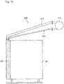
cooling system 900, exemplified inFigs. 11 and12 , is known. UsingFigs. 11 and12 , therelated cooling system 900 will be described.Figs. 11 and12 are a plan view and a side view of therelated cooling system 900, respectively. - A
cooling device 920 of thecooling system 900 includes anevaporating unit 927, aflexible tube 923, and arefrigerant relay 912. Therefrigerant relay 912 is disposed at a position distanced from the evaporatingunit 927. Therefrigerant relay 912 and theevaporator 927 are connected to each other by means of theflexible tube 923, and theflexible tube 923 is made longer than the straight line distance between therefrigerant relay 912 and theevaporator 927, that is, is disposed provided with a surplus length. The configuration of thecooling device 920 enables opening and closing of the rear-surface door even when the diameter of theflexible tube 923 is increased. - Note that other technologies related to the present invention are also disclosed in
PTLs 2 and 3. -
- [PTL 1]
JP 2009-134531 A - [PTL 2]
JP 2012-179728 A - [PTL 3]
JP 2006-101817 A - However, the above-described
cooling device 920 having therefrigerant relay 912 and theevaporator 927 distanced from each other causes an increase in the space for installation. For this reason, while thecooling device 920 has no problem when there is enough space for installing a lot of casings in a data center, a lot ofcooling devices 920 cannot be installed in the data center when enough space is not available. In addition, in thecooling device 920, disposition of therefrigerant relay 912 closer to the side on which theevaporator 927 is disposed causes theflexible tube 923 to extend out of the place for installation, which eventually increases the space for installation. This constraint requires thecooling device 900 to secure a distance equal to or longer than a predetermined distance between thecasing 912 and other casings, which has caused an increase in the space for installation. - An object of the present invention is to provide a cooling device and a cooling system that are capable of suppressing an increase in space for installation.
- In order to achieve the above-described object, a cooling device according to the present invention includes: an evaporator that is disposed on a rear-surface door that is mounted on a casing in an openable and closable manner; a refrigerant relay that is placed above the casing and connected to a condenser; and a freely bendable flexible tube one end and the other end of which are connected to the evaporator and a side of the refrigerant relay different from a side of the refrigerant relay on which the evaporator is disposed, respectively, wherein at least a portion of the flexible tube is disposed below the refrigerant relay so as to cross the refrigerant relay in a grade-separated manner.
- In order to achieve the above-described object, the cooling device according to the present invention includes a plurality of the evaporators, wherein each of the plurality of the evaporators is connected to the refrigerant relay.
- The present invention enables an increase in space for installation to be suppressed.
-
- [
Fig. 1] Fig. 1 is a plan view of a cooling system according to an example embodiment (first example embodiment) of the present invention; - [
Fig. 2] Fig. 2 is a plan view of a cooling system according to another example embodiment (second example embodiment) of the present invention; - [
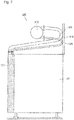
Fig. 3] Fig. 3 is a side view of the cooling system according to the another example embodiment (second example embodiment) of the present invention; - [
Fig. 4] Fig. 4 is a plan view of the cooling system according to the another example embodiment (second example embodiment) of the present invention and a diagram illustrating a state in which a rear-surface door of a casing is opened; - [
Fig. 5] Fig. 5 is a side view of the cooling system according to the another example embodiment (second example embodiment) of the present invention and another diagram illustrating the state in which the rear-surface door of the casing is opened; - [
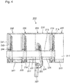
Fig. 6] Fig. 6 is a plan view of a cooling system according to still another example embodiment (third example embodiment) of the present invention; - [
Fig. 7] Fig. 7 is a side view of the cooling system according to the still another example embodiment (third example embodiment) of the present invention; - [
Fig. 8] Fig. 8 is a rear view of the cooling system according to the still another example embodiment (third example embodiment) of the present invention; - [
Fig. 9] Figs. 9 is a plan view of the cooling system according to the still another example embodiment (third example embodiment) of the present invention and a diagram illustrating a state in which a rear-surface door of a casing is opened; - [
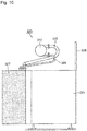
Fig. 10] Fig. 10 is a side view of the cooling system according to the still another example embodiment (third example embodiment) of the present invention and another diagram illustrating the state in which the rear-surface door of the casing is opened; - [
Fig. 11] Fig. 11 is a plan view of a related cooling system; and - [
Fig. 12] Fig. 12 is a side view of the related cooling system. - Hereinafter, example embodiments of the present invention will be described using the drawings.
- An example embodiment (first example embodiment) of the present invention will be described using
Fig. 1. Fig. 1 is a plan view of acooling system 100 according to the present example embodiment (first example embodiment). Thecooling system 100 is configured including a plurality of coolingdevices refrigerant relay 112 that is connected to the respective ones of the plurality of coolingdevices devices cooling device 120 will be described and a description of theother cooling devices - The
cooling device 120 is configured including anevaporator 127, therefrigerant relay 112, and aflexible tube 123. Theevaporator 127 is disposed on a rear-surface door that is mounted on acasing 121 in an openable and closable manner. Therefrigerant relay 112 is placed above thecasing 121 and connected to a not-illustrated condenser. Theflexible tube 123 has one end and the other end connected to theevaporator 127 and a side of therefrigerant relay 112 different from the side thereof on which theevaporator 127 is disposed, respectively. Theflexible tube 123 is configured so as to be freely bendable. In addition, at least a portion of theflexible tube 123 is disposed below therefrigerant relay 112 so as to cross therefrigerant relay 112 in a grade-separated manner. In the above, the side of therefrigerant relay 112 on which theevaporator 127 is disposed and the side of therefrigerant relay 112 different therefrom correspond to the rear-surface side and the front-surface side of thecasing 121, respectively. In other words, the other end of theflexible tube 123 is connected to the front-surface side of therefrigerant relay 112 with respect to thecasing 121. In addition, the crossing in a grade-separated manner corresponds to, by making theflexible tube 123, after passing below therefrigerant relay 112 from the side on which theevaporator 127 is disposed, reverse the extending direction thereof and be connected to therefrigerant relay 112, making therefrigerant relay 112 and theflexible tube 123 cross each other above thecasing 121. - As described above, the
cooling device 120 has therefrigerant relay 112 placed above thecasing 121 and theflexible tube 123 connected to theevaporator 127 and the side of therefrigerant relay 112 different from the side thereof on which theevaporator 127 is disposed. Making therefrigerant relay 112 and theflexible tube 123 cross each other in a grade-separated manner enables thecooling device 120 to keep therefrigerant relay 112 and theflexible tube 123 contained within an area above a space for installation of thecasing 121. In consequence, an increase in space for installation may be suppressed in the present example embodiment. - Another example embodiment (second example embodiment) of the present invention will be described using
Figs. 2 to 5 .Figs. 2 and3 are a plan view and a side view of acooling system 200 according to the present example embodiment (second example embodiment), respectively.Figs. 4 and5 are a plan view and a side view of thecooling system 200 according to the present example embodiment (second example embodiment), respectively, and diagrams illustrating a state in which a rear-surface door of acasing 221 is opened. - The
cooling system 200 is configured including a plurality of coolingdevices devices cooling device 220 will be described and a description of theother cooling devices cooling device 220 is configured including an evaporatingunit 227, a not-illustrated condensing unit, arefrigerant relay 212, arefrigerant vapor tube 223, and a refrigerantliquid tube 224. - The evaporating
unit 227 of thecooling device 220 is disposed so as to cover the rear-surface side of thecasing 221. In the present example embodiment, thecasing 221 is made up of a top surface, a bottom surface, a front surface, a rear surface, and side surfaces and is formed constituting a rectangular parallelepiped shape. Note that, hereinafter, the surface illustrated inFig. 2 is referred to as the top surface, and the upper side, the lower side, and the right and left sides in theFig. 2 are referred to as the front surface, the rear surface, and the side surfaces, respectively. In addition, based on the above definition, the up and down direction, the right and left direction, and the depth direction in theFig. 2 are referred to as a front-to-rear direction, a side-to-side direction, and a top-to-bottom direction, respectively. - The evaporating
unit 227 functions as the rear-surface door of thecasing 221 and is mounted on thecasing 221 in a freely openable and closable manner by means of a not-illustrated metal fitting having a rotating shaft. In addition, the evaporatingunit 227 is thermally connected to not-illustrated electronic devices contained inside thecasing 221, and evaporation of refrigerant liquid stored inside the evaporatingunit 227 takes heat away from the electronic devices. Note that, since the electronic devices are known technologies, a description thereof will be omitted. The evaporatingunit 227 cools a heating element by, when taking heat away from the heating element, making the stored refrigerant liquid undergo a phase change to vapor (hereinafter, the vapor is referred to as refrigerant vapor). At this time, emitted heat from the heating element is absorbed by the refrigerant vapor. The refrigerant vapor flows into therefrigerant relay 212 via the refrigerant vapor tube. Further, the refrigerant vapor flows into a not-illustrated heat exchanger from therefrigerant relay 212. - The condensing unit is installed at a higher position than the evaporating
unit 227. The condensing unit makes the refrigerant vapor undergo a phase change to liquid (hereinafter, the liquid is referred to as refrigerant liquid) and radiates heat. At this time, the condensing unit condenses and liquefies the refrigerant vapor by performing heat exchange with a low temperature medium, such as air. - The
refrigerant vapor tube 223 serves as a flow path for flowing refrigerant vapor generated through a phase change in the evaporatingunit 227 from the evaporatingunit 227 to therefrigerant relay 212 by use of the buoyancy of the refrigerant vapor. In the present example embodiment, therefrigerant vapor tube 223 is configured using a freely bendable flexible tube made of metal. Note that, although, in the present example embodiment, therefrigerant vapor tube 223 is assumed to be made of metal, that is because therefrigerant vapor tube 223 made of resin, such as rubber and Teflon (Registered Trademark), causes air to permeate from the outside into the inside and lower the degree of vacuum, and, thus, the material constituting therefrigerant vapor tube 223 is not limited to a metal as long as satisfying the degree of vacuum described above. One end and the other end of therefrigerant vapor tube 223 are connected to therefrigerant relay 212 and the evaporatingunit 227 on thecasing 221, respectively. Note that, although the size of therefrigerant vapor tube 223 is not limited to a specific value, the size may, as an example, be set at an inner diameter of approximately 50 mm when, for example, heat of 15 kW is transported. As another example, the size may be set at an inner diameter of approximately 65mm when, for example, heat of 30kW is transported. - The refrigerant
liquid tube 224 serves as a flow path for flowing refrigerant liquid generated through a phase change in the heat exchanger from therefrigerant relay 212 on the upstream side to the evaporatingunit 227 on the downstream side by use of the gravity of the refrigerant liquid. The refrigerantliquid tube 224 is also configured using a freely bendable flexible tube as with therefrigerant vapor tube 223. One end and the other end of the refrigerantliquid tube 224 are also connected to therefrigerant relay 212 and the evaporatingunit 227, respectively, as with therefrigerant vapor tube 223. - In the above configuration, the evaporating
unit 227 functions as a rear-surface door that opens and closes by rotating around the rotating shaft, as described above. For this reason, as the rear-surface door opens and closes, the positions of the other ends of therefrigerant vapor tube 223 and the refrigerantliquid tube 224 are drawn in the rear-surface direction of thecasing 221. Therefore, in the present example embodiment, allowing therefrigerant vapor tube 223 and the refrigerantliquid tube 224 to be bent and stretched using surplus length and flexibility that therefrigerant vapor tube 223 and the refrigerantliquid tube 224 have enables opening and closing of the rear-surface door. In consequence, it becomes possible to, while retaining the connection between therefrigerant relay 212 and the evaporatingunit 227, open and close the evaporatingunit 227 as a rear-surface door. - The
refrigerant relay 212 has a cylindrical shape and is extended along the side-to-side direction of thecasing 221. Note that, although, in the present example embodiment, therefrigerant relay 212 is formed into a cylindrical shape, the cross-sectional shape thereof is not limited to a circular shape and may be formed into, for example, a rectangular shape. In addition, therefrigerant relay 212 is, as described above, disposed in an area above the top surface of thecasing 221. On the other hand, in the above-describedrelated cooling system 900, in order to secure the surplus length of theflexible tube 923, therefrigerant relay 912 is disposed, instead of in an area above the space for installation of thecasing 921, at a position outside the space for installation of thecasing 921, as described above. For this reason, in therelated cooling system 900, another casing cannot be installed in a space on the front-surface side of thecasing 921, and, when a sufficient space for installation is not available, it is impossible to install a lot of casings. By contrast, in the present example embodiment, therefrigerant relay 212 is disposed within the space for installation of thecasing 221. In the present example embodiment, this dispositional configuration enables a saving in space for installation to be achieved. - In the present example embodiment, the
refrigerant relay 212 is placed at a position between substantially the middle and the rear-surface side in the front-to-rear direction of thecasing 221. In addition, therefrigerant relay 212 is placed at a position distanced by a predetermined height from the top surface of thecasing 221. This configuration enables therefrigerant vapor tube 223 and the refrigerantliquid tube 224 to be bent and disposed within an area in the space for installation of thecasing 221. Note that, although the position at which therefrigerant relay 212 is disposed is not limited to a specific position as long as being located between substantially the middle and the rear-surface side in the front-to-rear direction of thecasing 221, therefrigerant relay 212 may preferably be positioned at substantially the middle. This configuration enables a sense of oppression given to users by therefrigerant relay 212 to be suppressed. - On the
casing 221, a capping 218 is disposed. Note that the capping 218 is a component for controlling air flow in air conditioning and a product for achieving an efficient air conditioning environment by partitioning passages around the respective casings using walls, roofs, and the like and physically separating intake air (low temperature) and exhaust air (high temperature) to/from electronic devices. The capping 218 is erected at the edge on the front-surface side of thecasing 221. This configuration enables the capping 218 to partition an area above the top surface of thecasing 221 from an area on the front-surface side of thecasing 221 and reduce influence of air flow on refrigerant flowing through therefrigerant relay 212, therefrigerant vapor tube 223, and the refrigerantliquid tube 224. - On the other hand, in the
related cooling system 900, therefrigerant relay 912 is disposed at a position outside an area equivalent to the space for installation of thecasing 921. For this reason, disposition of a capping to thecooling system 900 causes a necessity to open a hole through which therefrigerant vapor tube 923 is inserted on the capping. By contrast, in thecooling system 200 of the present example embodiment, since therefrigerant vapor tube 223 is disposed within the space for installation of thecasing 221, it is not necessary to open a hole in the capping 218 that allows therefrigerant vapor tube 223 to pass therethrough, which enables air flow to be shielded more securely. - As described above, even when a tube that cannot be twisted, like the
refrigerant vapor tube 223 made of metal, is used, the present example embodiment enables opening and closing of the rear-surface door with the connection of therefrigerant vapor tube 223 to the rear-surface door retained. In addition, even when therefrigerant vapor tube 223 is provided with surplus length in order to enable opening and closing of the rear-surface door, it becomes possible to keep therefrigerant vapor tube 223 contained within the space for installation of thecasing 221. In consequence, the present example embodiment enables an increase in space for installation to be suppressed and more casings to be installed in a data center. - Still another example embodiment (third example embodiment) of the present invention will be described using
Figs. 6 to 10 .Figs. 6 to 8 are a plan view, a side view, and a rear view of acooling device 300 according to the present example embodiment (third example embodiment), respectively.Figs. 9 and10 are a plan view and a side view of thecooling system 300 according to the present example embodiment (third example embodiment), respectively, and diagrams illustrating a state in which a rear-surface door of acasing 321 is opened. Note that acooling device 320 of thecooling system 300 of the present example embodiment is similar to thecooling device 220 of the second example embodiment described above except a difference in that arefrigerant vapor tube 323 and a refrigerantliquid tube 324 have a plurality of bend parts. Therefore, corresponding signs are assigned to the same components as those in thecooling device 220 of the second example embodiment described above and a description thereof will be omitted. - In the present example embodiment, the
refrigerant vapor tube 323 and the refrigerantliquid tube 324 are disposed having a plurality of bend parts. In this configuration, refrigerant flowing through therefrigerant vapor tube 323 is a mixed two phase flow of vapor and liquid. The liquid ascends toward arefrigerant relay 312 dragged by the force of vapor flow. On this occasion, in the above-described second example embodiment, although the liquid flows along a lowest portion of the inner surface of therefrigerant vapor tube 223 until reaching a middle point, after the middle point, the inclination of therefrigerant vapor tube 223 turns to a reverse inclination, which causes the liquid flow to switch flow paths. For this reason, in the above-described second example embodiment, there is a possibility that the liquid flow switching phenomenon causes a vibration of therefrigerant vapor tube 223 to occur and the life of therefrigerant vapor tube 223 to be shortened. In addition, in the above-described second example embodiment, there is also a possibility that crossing of the liquid and the vapor at a position where the liquid flow switches flow paths causes the vapor flow to be hindered and a reduction in performance to be induced. By contrast, since, as described above, therefrigerant vapor tube 323 of the present example embodiment has a plurality of bend parts and a portion ascending to therefrigerant relay 312 is formed to obliquely ascend, there is no turn to a reverse inclination and the liquid continuously ascends along lowest portions in cross sections of therefrigerant vapor tube 323. For this reason, the present example embodiment neither hinders the flow of vapor nor causes a vibration of therefrigerant vapor tube 323 to occur, which enables the life of therefrigerant vapor tube 323 to be prevented from deteriorating. - As described above, the present example embodiment also enables opening and closing of the rear-surface door with the connection of the
refrigerant vapor tube 323 to the rear-surface door retained. In addition, even when therefrigerant vapor tube 323 is provided with surplus length in order to enable opening and closing of the rear-surface door, it becomes possible to keep therefrigerant vapor tube 323 contained within the space for installation of thecasing 321. In consequence, the present example embodiment enables an increase in space for installation to be suppressed and more casings to be installed in a data center. - Further, since, as described above, a portion of the
refrigerant vapor tube 323 ascending to therefrigerant relay 312 is formed to obliquely ascend, the present example embodiment neither hinders the flow of vapor nor causes a vibration of therefrigerant vapor tube 323 to occur, which enables the life of therefrigerant vapor tube 323 to be prevented from deteriorating. - The present invention was described above through example embodiments (and examples) thereof, but the present invention is not limited to the above example embodiments (and examples). Various modifications that could be understood by a person skilled in the art may be applied to the configurations and details of the present invention within the scope of the present invention.
- In addition, all or part of the example embodiments described afore may be described as follows, but not limited thereto.
- A cooling device, including:
- an evaporator that is disposed on a rear-surface door that is mounted on a casing in an openable and closable manner;
- a refrigerant relay that is placed above the casing and connected to a condenser; and
- a freely bendable flexible tube one end and the other end of which are connected to the evaporator and a side of the refrigerant relay different from a side of the refrigerant relay on which the evaporator is disposed, respectively, wherein
- at least a portion of the flexible tube is disposed below the refrigerant relay so as to cross the refrigerant relay in a grade-separated manner.
- The cooling device according to supplementary note 1, wherein
the refrigerant relay is positioned at substantially a middle above the casing. - The cooling device according to
supplementary note 1 or 2, wherein
the flexible tube is disposed having a plurality of bend parts. - The cooling device according to any one of supplementary notes 1 to 3, wherein
at least a portion of the flexible tube is formed to extend obliquely upward from a region of the flexible tube positioned below the refrigerant relay toward the refrigerant relay. - The cooling device according to any one of supplementary notes 1 to 4, wherein
a side of the refrigerant relay different from a side of the refrigerant relay on which the evaporator is disposed is positioned on a front-surface side of the casing. - The cooling device according to any one of supplementary notes 1 to 5, including
a plurality of the evaporators, wherein
each of the plurality of the evaporators is connected to the refrigerant relay by means of the flexible tube. - A cooling device, including:
- an evaporator that is disposed on a rear-surface door that is mounted on a casing in an openable and closable manner;
- a refrigerant relay that is placed above the casing and connected to a condenser; and
- a freely bendable flexible tube one end and the other end of which are connected to the evaporator and a side of the refrigerant relay different from a side of the refrigerant relay on which the evaporator is disposed, respectively, wherein
- at least a portion of the flexible tube is disposed below the refrigerant relay so as to cross the refrigerant relay in a grade-separated manner.
- The cooling device according to supplementary note 7, wherein
the refrigerant relay is positioned at substantially a middle above the casing. - The cooling device according to supplementary note 7 or 8, wherein
the flexible tube is disposed having a plurality of bend parts. - The cooling device according to any one of supplementary notes 7 to 9, wherein
at least a portion of the flexible tube is formed to extend obliquely upward from a region of the flexible tube positioned below the refrigerant relay toward the refrigerant relay. - The cooling device according to any one of supplementary notes 7 to 10, wherein
a side of the refrigerant relay different from a side of the refrigerant relay on which the evaporator is disposed is positioned on a front-surface side of the casing. - A cooling system, including
a plurality of evaporators according to any one of supplementary notes 7 to 11, wherein
each of the plurality of the evaporators is connected to the refrigerant relay. - This application claims priority based on Japanese Patent Application No.
2015-203568, filed on Oct. 15, 2015 -
- 100 Cooling system
- 112 Coolant relay
- 120 Cooling device
- 121 Casing
- 123 Flexible tube
- 127 Evaporator
Claims (6)
- A cooling device, comprising:an evaporator that is disposed on a rear-surface door that is mounted on a casing in an openable and closable manner;a refrigerant relay that is placed above the casing and connected to a condenser; anda freely bendable flexible tube one end and the other end of which are connected to the evaporator and a side of the refrigerant relay different from a side of the refrigerant relay on which the evaporator is disposed, respectively, whereinat least a portion of the flexible tube is disposed below the refrigerant relay so as to cross the refrigerant relay in a grade-separated manner.
- The cooling device according to claim 1, wherein the refrigerant relay is positioned at substantially a middle above the casing.
- The cooling device according to claim 1 or 2, wherein the flexible tube is disposed having a plurality of bend parts.
- The cooling device according to any one of claims 1 to 3, wherein at least a portion of the flexible tube is formed to extend obliquely upward from a region of the flexible tube positioned below the refrigerant relay toward the refrigerant relay.
- The cooling device according to any one of claims 1 to 4, wherein a side of the refrigerant relay different from a side of the refrigerant relay on which the evaporator is disposed is positioned on a front-surface side of the casing.
- The cooling device according to any one of claims 1 to 5, comprising
a plurality of the evaporators, wherein
each of the plurality of the evaporators is connected to the refrigerant relay by means of the flexible tube.
Applications Claiming Priority (2)
| Application Number | Priority Date | Filing Date | Title |
|---|---|---|---|
| JP2015203568A JP6034465B1 (en) | 2015-10-15 | 2015-10-15 | Cooling device and cooling system |
| PCT/JP2016/004593 WO2017064872A1 (en) | 2015-10-15 | 2016-10-14 | Cooling device and cooling system |
Publications (3)
| Publication Number | Publication Date |
|---|---|
| EP3364140A1 true EP3364140A1 (en) | 2018-08-22 |
| EP3364140A4 EP3364140A4 (en) | 2019-06-19 |
| EP3364140B1 EP3364140B1 (en) | 2021-12-01 |
Family
ID=57419810
Family Applications (1)
| Application Number | Title | Priority Date | Filing Date |
|---|---|---|---|
| EP16855126.5A Active EP3364140B1 (en) | 2015-10-15 | 2016-10-14 | Cooling device |
Country Status (5)
| Country | Link |
|---|---|
| US (1) | US20180320982A1 (en) |
| EP (1) | EP3364140B1 (en) |
| JP (1) | JP6034465B1 (en) |
| SG (1) | SG11201803037YA (en) |
| WO (1) | WO2017064872A1 (en) |
Families Citing this family (6)
| Publication number | Priority date | Publication date | Assignee | Title |
|---|---|---|---|---|
| JP5986064B2 (en) * | 2013-12-25 | 2016-09-06 | Necプラットフォームズ株式会社 | Cooling system and electronic equipment |
| US20170311485A1 (en) * | 2014-09-26 | 2017-10-26 | Nec Corporation | Cooling device and method of manufacturing the same |
| JP6424936B1 (en) * | 2017-10-04 | 2018-11-21 | 日本電気株式会社 | Gas-liquid separation device, rear door, cooling device, and gas-liquid separation method |
| JP6579633B2 (en) * | 2017-10-20 | 2019-09-25 | Necプラットフォームズ株式会社 | apparatus |
| US11729940B2 (en) * | 2021-11-02 | 2023-08-15 | Oracle International Corporation | Unified control of cooling in computers |
| US11711908B1 (en) * | 2022-03-18 | 2023-07-25 | Baidu Usa Llc | System and method for servicing and controlling a leak segregation and detection system of an electronics rack |
Family Cites Families (19)
| Publication number | Priority date | Publication date | Assignee | Title |
|---|---|---|---|---|
| JPS5714453U (en) * | 1980-06-30 | 1982-01-25 | ||
| JPH0328282Y2 (en) * | 1985-04-08 | 1991-06-18 | ||
| US6393853B1 (en) * | 2000-12-19 | 2002-05-28 | Nortel Networks Limited | Liquid cooling of removable electronic modules based on low pressure applying biasing mechanisms |
| DE202006007275U1 (en) * | 2006-05-06 | 2006-09-07 | Schroff Gmbh | Sub-rack with housing for receiving plug-in modules, has liquid distributor joined to heat-sink via forward- and return-line |
| US7882890B2 (en) * | 2007-07-13 | 2011-02-08 | International Business Machines Corporation | Thermally pumped liquid/gas heat exchanger for cooling heat-generating devices |
| US7950244B2 (en) * | 2007-11-14 | 2011-05-31 | International Business Machines Corporation | Apparatus for facilitating cooling of an electronics rack through the use of an air-to-liquid heat exchanger |
| JP2009193137A (en) * | 2008-02-12 | 2009-08-27 | Sanyo Electric Co Ltd | Electronic equipment cooling system |
| US8250877B2 (en) * | 2008-03-10 | 2012-08-28 | Cooligy Inc. | Device and methodology for the removal of heat from an equipment rack by means of heat exchangers mounted to a door |
| FR2931961B1 (en) * | 2008-06-02 | 2010-06-11 | Bull Sas | DEVICE FOR COOLING A COMPUTER BAY AND COMPUTER-BASED INSTALLATION COMPRISING SUCH A DEVICE |
| JP2010041007A (en) * | 2008-08-08 | 2010-02-18 | Hitachi Information & Communication Engineering Ltd | Cooling unit, electronic apparatus rack, cooling system, and construction method thereof |
| CN101814469A (en) * | 2009-02-20 | 2010-08-25 | 王玉富 | Gravity circulation evaporation cooling semiconductor power device package |
| US7965509B2 (en) * | 2009-04-06 | 2011-06-21 | International Business Machines Corporation | High performance dual-in-line memory (DIMM) array liquid cooling assembly and method |
| US8077462B2 (en) * | 2009-09-02 | 2011-12-13 | International Business Machines Corporation | Stress relieved hose routing to liquid-cooled electronics rack door |
| WO2011122207A1 (en) * | 2010-03-30 | 2011-10-06 | 日本電気株式会社 | Cooling apparatus and cooling system for electronic-device exhaustion |
| US8804334B2 (en) * | 2011-05-25 | 2014-08-12 | International Business Machines Corporation | Multi-rack, door-mounted heat exchanger |
| US9167721B2 (en) * | 2011-11-29 | 2015-10-20 | International Business Machines Corporation | Direct facility coolant cooling of a rack-mounted heat exchanger |
| EP2816881B1 (en) * | 2012-02-14 | 2018-10-03 | Nec Corporation | Cooling device and cooling system |
| US9016352B2 (en) * | 2012-05-21 | 2015-04-28 | Calvary Applied Technologies, LLC | Apparatus and methods for cooling rejected heat from server racks |
| US9877416B2 (en) * | 2015-08-24 | 2018-01-23 | Lenovo Enterprise Solutions (Singapore) Pte. Ltd. | Heat management in a server rack |
-
2015
- 2015-10-15 JP JP2015203568A patent/JP6034465B1/en active Active
-
2016
- 2016-10-14 SG SG11201803037YA patent/SG11201803037YA/en unknown
- 2016-10-14 US US15/768,341 patent/US20180320982A1/en not_active Abandoned
- 2016-10-14 EP EP16855126.5A patent/EP3364140B1/en active Active
- 2016-10-14 WO PCT/JP2016/004593 patent/WO2017064872A1/en not_active Ceased
Also Published As
| Publication number | Publication date |
|---|---|
| SG11201803037YA (en) | 2018-05-30 |
| JP2017075737A (en) | 2017-04-20 |
| WO2017064872A1 (en) | 2017-04-20 |
| US20180320982A1 (en) | 2018-11-08 |
| JP6034465B1 (en) | 2016-11-30 |
| EP3364140A4 (en) | 2019-06-19 |
| EP3364140B1 (en) | 2021-12-01 |
Similar Documents
| Publication | Publication Date | Title |
|---|---|---|
| EP3364140B1 (en) | Cooling device | |
| JP6069505B2 (en) | Cooling equipment for parts placed inside the switch cabinet | |
| JP6559799B2 (en) | Cooling unit for cooling the air received inside the switch cabinet and corresponding switchgear cabinet assembly | |
| EP3073813B1 (en) | Electronic apparatus enclosure device and electronic apparatus cooling system | |
| US20160014933A1 (en) | Electronic apparatus cooling system and electronic apparatus cooling system fabrication method | |
| US8094451B2 (en) | Onboard computer equipped with a stand-alone aeraulic cooling device | |
| EP2827691A2 (en) | Cabinet for power electronic apparatus | |
| JP4749356B2 (en) | Induction heating cooker | |
| EP2716982A2 (en) | Air conditioner outdoor unit | |
| EP3366095B1 (en) | Cooling systems for small equipment rooms and methods of cooling small equipment rooms | |
| CN105829822A (en) | Refrigerant distribution device and cooling device | |
| US20140308887A1 (en) | Blade assembly and air conditioner having the same | |
| US20150316279A1 (en) | Outdoor unit for air-conditioning apparatus | |
| EP2667105B1 (en) | Air conditioner | |
| EP3026356B1 (en) | Outdoor unit for air-conditioning apparatus | |
| JP5008375B2 (en) | Induction heating cooker | |
| CN108027153B (en) | Outdoor machine | |
| EP3078518B1 (en) | Vehicle air-conditioning apparatus | |
| JP7304640B2 (en) | Computer rack equipment that utilizes the cooling part | |
| CN105103666B (en) | Cable passage and air duct and corresponding switch cubicle for the combination of switch cubicle air-conditioning equipment | |
| EP2966368A2 (en) | Controller provided with heating electronic components, and air conditioner | |
| US10788270B2 (en) | Cooling device | |
| US20170311481A1 (en) | Cooling system and electronic device | |
| KR102656060B1 (en) | Overhead type air conditioning apparatus for automotive vehicle | |
| CN105517920A (en) | Refrigerated container assembly |
Legal Events
| Date | Code | Title | Description |
|---|---|---|---|
| STAA | Information on the status of an ep patent application or granted ep patent |
Free format text: STATUS: THE INTERNATIONAL PUBLICATION HAS BEEN MADE |
|
| PUAI | Public reference made under article 153(3) epc to a published international application that has entered the european phase |
Free format text: ORIGINAL CODE: 0009012 |
|
| STAA | Information on the status of an ep patent application or granted ep patent |
Free format text: STATUS: REQUEST FOR EXAMINATION WAS MADE |
|
| 17P | Request for examination filed |
Effective date: 20180515 |
|
| AK | Designated contracting states |
Kind code of ref document: A1 Designated state(s): AL AT BE BG CH CY CZ DE DK EE ES FI FR GB GR HR HU IE IS IT LI LT LU LV MC MK MT NL NO PL PT RO RS SE SI SK SM TR |
|
| AX | Request for extension of the european patent |
Extension state: BA ME |
|
| DAV | Request for validation of the european patent (deleted) | ||
| DAX | Request for extension of the european patent (deleted) | ||
| A4 | Supplementary search report drawn up and despatched |
Effective date: 20190517 |
|
| RIC1 | Information provided on ipc code assigned before grant |
Ipc: H01L 23/427 20060101ALI20190513BHEP Ipc: H05K 7/20 20060101ALI20190513BHEP Ipc: F28D 15/02 20060101AFI20190513BHEP |
|
| STAA | Information on the status of an ep patent application or granted ep patent |
Free format text: STATUS: EXAMINATION IS IN PROGRESS |
|
| 17Q | First examination report despatched |
Effective date: 20191212 |
|
| GRAP | Despatch of communication of intention to grant a patent |
Free format text: ORIGINAL CODE: EPIDOSNIGR1 |
|
| STAA | Information on the status of an ep patent application or granted ep patent |
Free format text: STATUS: GRANT OF PATENT IS INTENDED |
|
| INTG | Intention to grant announced |
Effective date: 20210720 |
|
| GRAS | Grant fee paid |
Free format text: ORIGINAL CODE: EPIDOSNIGR3 |
|
| GRAA | (expected) grant |
Free format text: ORIGINAL CODE: 0009210 |
|
| STAA | Information on the status of an ep patent application or granted ep patent |
Free format text: STATUS: THE PATENT HAS BEEN GRANTED |
|
| AK | Designated contracting states |
Kind code of ref document: B1 Designated state(s): AL AT BE BG CH CY CZ DE DK EE ES FI FR GB GR HR HU IE IS IT LI LT LU LV MC MK MT NL NO PL PT RO RS SE SI SK SM TR |
|
| REG | Reference to a national code |
Ref country code: GB Ref legal event code: FG4D |
|
| REG | Reference to a national code |
Ref country code: AT Ref legal event code: REF Ref document number: 1452145 Country of ref document: AT Kind code of ref document: T Effective date: 20211215 Ref country code: CH Ref legal event code: EP |
|
| REG | Reference to a national code |
Ref country code: IE Ref legal event code: FG4D |
|
| REG | Reference to a national code |
Ref country code: DE Ref legal event code: R096 Ref document number: 602016066958 Country of ref document: DE |
|
| REG | Reference to a national code |
Ref country code: LT Ref legal event code: MG9D |
|
| REG | Reference to a national code |
Ref country code: NL Ref legal event code: MP Effective date: 20211201 |
|
| REG | Reference to a national code |
Ref country code: AT Ref legal event code: MK05 Ref document number: 1452145 Country of ref document: AT Kind code of ref document: T Effective date: 20211201 |
|
| PG25 | Lapsed in a contracting state [announced via postgrant information from national office to epo] |
Ref country code: RS Free format text: LAPSE BECAUSE OF FAILURE TO SUBMIT A TRANSLATION OF THE DESCRIPTION OR TO PAY THE FEE WITHIN THE PRESCRIBED TIME-LIMIT Effective date: 20211201 Ref country code: LT Free format text: LAPSE BECAUSE OF FAILURE TO SUBMIT A TRANSLATION OF THE DESCRIPTION OR TO PAY THE FEE WITHIN THE PRESCRIBED TIME-LIMIT Effective date: 20211201 Ref country code: FI Free format text: LAPSE BECAUSE OF FAILURE TO SUBMIT A TRANSLATION OF THE DESCRIPTION OR TO PAY THE FEE WITHIN THE PRESCRIBED TIME-LIMIT Effective date: 20211201 Ref country code: BG Free format text: LAPSE BECAUSE OF FAILURE TO SUBMIT A TRANSLATION OF THE DESCRIPTION OR TO PAY THE FEE WITHIN THE PRESCRIBED TIME-LIMIT Effective date: 20220301 Ref country code: AT Free format text: LAPSE BECAUSE OF FAILURE TO SUBMIT A TRANSLATION OF THE DESCRIPTION OR TO PAY THE FEE WITHIN THE PRESCRIBED TIME-LIMIT Effective date: 20211201 |
|
| PG25 | Lapsed in a contracting state [announced via postgrant information from national office to epo] |
Ref country code: SE Free format text: LAPSE BECAUSE OF FAILURE TO SUBMIT A TRANSLATION OF THE DESCRIPTION OR TO PAY THE FEE WITHIN THE PRESCRIBED TIME-LIMIT Effective date: 20211201 Ref country code: PL Free format text: LAPSE BECAUSE OF FAILURE TO SUBMIT A TRANSLATION OF THE DESCRIPTION OR TO PAY THE FEE WITHIN THE PRESCRIBED TIME-LIMIT Effective date: 20211201 Ref country code: NO Free format text: LAPSE BECAUSE OF FAILURE TO SUBMIT A TRANSLATION OF THE DESCRIPTION OR TO PAY THE FEE WITHIN THE PRESCRIBED TIME-LIMIT Effective date: 20220301 Ref country code: LV Free format text: LAPSE BECAUSE OF FAILURE TO SUBMIT A TRANSLATION OF THE DESCRIPTION OR TO PAY THE FEE WITHIN THE PRESCRIBED TIME-LIMIT Effective date: 20211201 Ref country code: HR Free format text: LAPSE BECAUSE OF FAILURE TO SUBMIT A TRANSLATION OF THE DESCRIPTION OR TO PAY THE FEE WITHIN THE PRESCRIBED TIME-LIMIT Effective date: 20211201 Ref country code: GR Free format text: LAPSE BECAUSE OF FAILURE TO SUBMIT A TRANSLATION OF THE DESCRIPTION OR TO PAY THE FEE WITHIN THE PRESCRIBED TIME-LIMIT Effective date: 20220302 Ref country code: ES Free format text: LAPSE BECAUSE OF FAILURE TO SUBMIT A TRANSLATION OF THE DESCRIPTION OR TO PAY THE FEE WITHIN THE PRESCRIBED TIME-LIMIT Effective date: 20211201 |
|
| PG25 | Lapsed in a contracting state [announced via postgrant information from national office to epo] |
Ref country code: NL Free format text: LAPSE BECAUSE OF FAILURE TO SUBMIT A TRANSLATION OF THE DESCRIPTION OR TO PAY THE FEE WITHIN THE PRESCRIBED TIME-LIMIT Effective date: 20211201 |
|
| PG25 | Lapsed in a contracting state [announced via postgrant information from national office to epo] |
Ref country code: SM Free format text: LAPSE BECAUSE OF FAILURE TO SUBMIT A TRANSLATION OF THE DESCRIPTION OR TO PAY THE FEE WITHIN THE PRESCRIBED TIME-LIMIT Effective date: 20211201 Ref country code: SK Free format text: LAPSE BECAUSE OF FAILURE TO SUBMIT A TRANSLATION OF THE DESCRIPTION OR TO PAY THE FEE WITHIN THE PRESCRIBED TIME-LIMIT Effective date: 20211201 Ref country code: RO Free format text: LAPSE BECAUSE OF FAILURE TO SUBMIT A TRANSLATION OF THE DESCRIPTION OR TO PAY THE FEE WITHIN THE PRESCRIBED TIME-LIMIT Effective date: 20211201 Ref country code: PT Free format text: LAPSE BECAUSE OF FAILURE TO SUBMIT A TRANSLATION OF THE DESCRIPTION OR TO PAY THE FEE WITHIN THE PRESCRIBED TIME-LIMIT Effective date: 20220401 Ref country code: EE Free format text: LAPSE BECAUSE OF FAILURE TO SUBMIT A TRANSLATION OF THE DESCRIPTION OR TO PAY THE FEE WITHIN THE PRESCRIBED TIME-LIMIT Effective date: 20211201 Ref country code: CZ Free format text: LAPSE BECAUSE OF FAILURE TO SUBMIT A TRANSLATION OF THE DESCRIPTION OR TO PAY THE FEE WITHIN THE PRESCRIBED TIME-LIMIT Effective date: 20211201 |
|
| REG | Reference to a national code |
Ref country code: DE Ref legal event code: R097 Ref document number: 602016066958 Country of ref document: DE |
|
| PG25 | Lapsed in a contracting state [announced via postgrant information from national office to epo] |
Ref country code: IS Free format text: LAPSE BECAUSE OF FAILURE TO SUBMIT A TRANSLATION OF THE DESCRIPTION OR TO PAY THE FEE WITHIN THE PRESCRIBED TIME-LIMIT Effective date: 20220401 |
|
| PLBE | No opposition filed within time limit |
Free format text: ORIGINAL CODE: 0009261 |
|
| STAA | Information on the status of an ep patent application or granted ep patent |
Free format text: STATUS: NO OPPOSITION FILED WITHIN TIME LIMIT |
|
| PG25 | Lapsed in a contracting state [announced via postgrant information from national office to epo] |
Ref country code: DK Free format text: LAPSE BECAUSE OF FAILURE TO SUBMIT A TRANSLATION OF THE DESCRIPTION OR TO PAY THE FEE WITHIN THE PRESCRIBED TIME-LIMIT Effective date: 20211201 Ref country code: AL Free format text: LAPSE BECAUSE OF FAILURE TO SUBMIT A TRANSLATION OF THE DESCRIPTION OR TO PAY THE FEE WITHIN THE PRESCRIBED TIME-LIMIT Effective date: 20211201 |
|
| 26N | No opposition filed |
Effective date: 20220902 |
|
| PG25 | Lapsed in a contracting state [announced via postgrant information from national office to epo] |
Ref country code: SI Free format text: LAPSE BECAUSE OF FAILURE TO SUBMIT A TRANSLATION OF THE DESCRIPTION OR TO PAY THE FEE WITHIN THE PRESCRIBED TIME-LIMIT Effective date: 20211201 |
|
| PG25 | Lapsed in a contracting state [announced via postgrant information from national office to epo] |
Ref country code: MC Free format text: LAPSE BECAUSE OF FAILURE TO SUBMIT A TRANSLATION OF THE DESCRIPTION OR TO PAY THE FEE WITHIN THE PRESCRIBED TIME-LIMIT Effective date: 20211201 Ref country code: IT Free format text: LAPSE BECAUSE OF FAILURE TO SUBMIT A TRANSLATION OF THE DESCRIPTION OR TO PAY THE FEE WITHIN THE PRESCRIBED TIME-LIMIT Effective date: 20211201 |
|
| REG | Reference to a national code |
Ref country code: CH Ref legal event code: PL |
|
| REG | Reference to a national code |
Ref country code: BE Ref legal event code: MM Effective date: 20221031 |
|
| PG25 | Lapsed in a contracting state [announced via postgrant information from national office to epo] |
Ref country code: LU Free format text: LAPSE BECAUSE OF NON-PAYMENT OF DUE FEES Effective date: 20221014 |
|
| PG25 | Lapsed in a contracting state [announced via postgrant information from national office to epo] |
Ref country code: LI Free format text: LAPSE BECAUSE OF NON-PAYMENT OF DUE FEES Effective date: 20221031 Ref country code: CH Free format text: LAPSE BECAUSE OF NON-PAYMENT OF DUE FEES Effective date: 20221031 |
|
| PG25 | Lapsed in a contracting state [announced via postgrant information from national office to epo] |
Ref country code: BE Free format text: LAPSE BECAUSE OF NON-PAYMENT OF DUE FEES Effective date: 20221031 |
|
| PG25 | Lapsed in a contracting state [announced via postgrant information from national office to epo] |
Ref country code: IE Free format text: LAPSE BECAUSE OF NON-PAYMENT OF DUE FEES Effective date: 20221014 |
|
| PG25 | Lapsed in a contracting state [announced via postgrant information from national office to epo] |
Ref country code: HU Free format text: LAPSE BECAUSE OF FAILURE TO SUBMIT A TRANSLATION OF THE DESCRIPTION OR TO PAY THE FEE WITHIN THE PRESCRIBED TIME-LIMIT; INVALID AB INITIO Effective date: 20161014 |
|
| PG25 | Lapsed in a contracting state [announced via postgrant information from national office to epo] |
Ref country code: CY Free format text: LAPSE BECAUSE OF FAILURE TO SUBMIT A TRANSLATION OF THE DESCRIPTION OR TO PAY THE FEE WITHIN THE PRESCRIBED TIME-LIMIT Effective date: 20211201 |
|
| PG25 | Lapsed in a contracting state [announced via postgrant information from national office to epo] |
Ref country code: MK Free format text: LAPSE BECAUSE OF FAILURE TO SUBMIT A TRANSLATION OF THE DESCRIPTION OR TO PAY THE FEE WITHIN THE PRESCRIBED TIME-LIMIT Effective date: 20211201 |
|
| PG25 | Lapsed in a contracting state [announced via postgrant information from national office to epo] |
Ref country code: TR Free format text: LAPSE BECAUSE OF FAILURE TO SUBMIT A TRANSLATION OF THE DESCRIPTION OR TO PAY THE FEE WITHIN THE PRESCRIBED TIME-LIMIT Effective date: 20211201 |
|
| PG25 | Lapsed in a contracting state [announced via postgrant information from national office to epo] |
Ref country code: MT Free format text: LAPSE BECAUSE OF FAILURE TO SUBMIT A TRANSLATION OF THE DESCRIPTION OR TO PAY THE FEE WITHIN THE PRESCRIBED TIME-LIMIT Effective date: 20211201 |
|
| PGFP | Annual fee paid to national office [announced via postgrant information from national office to epo] |
Ref country code: DE Payment date: 20251021 Year of fee payment: 10 |
|
| PGFP | Annual fee paid to national office [announced via postgrant information from national office to epo] |
Ref country code: GB Payment date: 20251022 Year of fee payment: 10 |
|
| PGFP | Annual fee paid to national office [announced via postgrant information from national office to epo] |
Ref country code: FR Payment date: 20251030 Year of fee payment: 10 |