EP3364076B1 - Control device of vehicle - Google Patents
Control device of vehicle Download PDFInfo
- Publication number
- EP3364076B1 EP3364076B1 EP18157258.7A EP18157258A EP3364076B1 EP 3364076 B1 EP3364076 B1 EP 3364076B1 EP 18157258 A EP18157258 A EP 18157258A EP 3364076 B1 EP3364076 B1 EP 3364076B1
- Authority
- EP
- European Patent Office
- Prior art keywords
- torque
- shift
- downshift
- engine
- control
- Prior art date
- Legal status (The legal status is an assumption and is not a legal conclusion. Google has not performed a legal analysis and makes no representation as to the accuracy of the status listed.)
- Active
Links
- 230000005540 biological transmission Effects 0.000 claims description 156
- 239000000446 fuel Substances 0.000 claims description 20
- 230000001133 acceleration Effects 0.000 claims description 18
- 230000001360 synchronised effect Effects 0.000 claims description 16
- ATJFFYVFTNAWJD-UHFFFAOYSA-N Tin Chemical compound [Sn] ATJFFYVFTNAWJD-UHFFFAOYSA-N 0.000 claims description 10
- 238000013459 approach Methods 0.000 claims description 6
- 230000007704 transition Effects 0.000 description 9
- 230000008859 change Effects 0.000 description 8
- 238000010586 diagram Methods 0.000 description 8
- 239000012530 fluid Substances 0.000 description 8
- 230000007935 neutral effect Effects 0.000 description 6
- 238000010168 coupling process Methods 0.000 description 4
- 238000005859 coupling reaction Methods 0.000 description 4
- 230000000052 comparative effect Effects 0.000 description 3
- 230000001276 controlling effect Effects 0.000 description 3
- 230000008878 coupling Effects 0.000 description 3
- 230000014509 gene expression Effects 0.000 description 3
- 230000007246 mechanism Effects 0.000 description 3
- 238000000034 method Methods 0.000 description 3
- 230000008569 process Effects 0.000 description 3
- 230000009467 reduction Effects 0.000 description 3
- 230000007423 decrease Effects 0.000 description 2
- 238000001514 detection method Methods 0.000 description 2
- 230000002542 deteriorative effect Effects 0.000 description 2
- 230000001105 regulatory effect Effects 0.000 description 2
- 230000035939 shock Effects 0.000 description 2
- 230000003321 amplification Effects 0.000 description 1
- 239000000969 carrier Substances 0.000 description 1
- 238000002485 combustion reaction Methods 0.000 description 1
- 230000003247 decreasing effect Effects 0.000 description 1
- 230000003111 delayed effect Effects 0.000 description 1
- 230000006866 deterioration Effects 0.000 description 1
- 230000009977 dual effect Effects 0.000 description 1
- 230000000694 effects Effects 0.000 description 1
- 230000002349 favourable effect Effects 0.000 description 1
- 238000002347 injection Methods 0.000 description 1
- 239000007924 injection Substances 0.000 description 1
- 238000005461 lubrication Methods 0.000 description 1
- 238000003199 nucleic acid amplification method Methods 0.000 description 1
- 230000002441 reversible effect Effects 0.000 description 1
- 230000001629 suppression Effects 0.000 description 1
- 230000002123 temporal effect Effects 0.000 description 1
Images


Classifications
-
- B—PERFORMING OPERATIONS; TRANSPORTING
- B60—VEHICLES IN GENERAL
- B60W—CONJOINT CONTROL OF VEHICLE SUB-UNITS OF DIFFERENT TYPE OR DIFFERENT FUNCTION; CONTROL SYSTEMS SPECIALLY ADAPTED FOR HYBRID VEHICLES; ROAD VEHICLE DRIVE CONTROL SYSTEMS FOR PURPOSES NOT RELATED TO THE CONTROL OF A PARTICULAR SUB-UNIT
- B60W30/00—Purposes of road vehicle drive control systems not related to the control of a particular sub-unit, e.g. of systems using conjoint control of vehicle sub-units
- B60W30/18—Propelling the vehicle
- B60W30/19—Improvement of gear change, e.g. by synchronisation or smoothing gear shift
-
- F—MECHANICAL ENGINEERING; LIGHTING; HEATING; WEAPONS; BLASTING
- F16—ENGINEERING ELEMENTS AND UNITS; GENERAL MEASURES FOR PRODUCING AND MAINTAINING EFFECTIVE FUNCTIONING OF MACHINES OR INSTALLATIONS; THERMAL INSULATION IN GENERAL
- F16H—GEARING
- F16H61/00—Control functions within control units of change-speed- or reversing-gearings for conveying rotary motion ; Control of exclusively fluid gearing, friction gearing, gearings with endless flexible members or other particular types of gearing
- F16H61/10—Controlling shift hysteresis
-
- B—PERFORMING OPERATIONS; TRANSPORTING
- B60—VEHICLES IN GENERAL
- B60W—CONJOINT CONTROL OF VEHICLE SUB-UNITS OF DIFFERENT TYPE OR DIFFERENT FUNCTION; CONTROL SYSTEMS SPECIALLY ADAPTED FOR HYBRID VEHICLES; ROAD VEHICLE DRIVE CONTROL SYSTEMS FOR PURPOSES NOT RELATED TO THE CONTROL OF A PARTICULAR SUB-UNIT
- B60W10/00—Conjoint control of vehicle sub-units of different type or different function
- B60W10/04—Conjoint control of vehicle sub-units of different type or different function including control of propulsion units
- B60W10/06—Conjoint control of vehicle sub-units of different type or different function including control of propulsion units including control of combustion engines
-
- B—PERFORMING OPERATIONS; TRANSPORTING
- B60—VEHICLES IN GENERAL
- B60W—CONJOINT CONTROL OF VEHICLE SUB-UNITS OF DIFFERENT TYPE OR DIFFERENT FUNCTION; CONTROL SYSTEMS SPECIALLY ADAPTED FOR HYBRID VEHICLES; ROAD VEHICLE DRIVE CONTROL SYSTEMS FOR PURPOSES NOT RELATED TO THE CONTROL OF A PARTICULAR SUB-UNIT
- B60W10/00—Conjoint control of vehicle sub-units of different type or different function
- B60W10/10—Conjoint control of vehicle sub-units of different type or different function including control of change-speed gearings
- B60W10/11—Stepped gearings
-
- F—MECHANICAL ENGINEERING; LIGHTING; HEATING; WEAPONS; BLASTING
- F16—ENGINEERING ELEMENTS AND UNITS; GENERAL MEASURES FOR PRODUCING AND MAINTAINING EFFECTIVE FUNCTIONING OF MACHINES OR INSTALLATIONS; THERMAL INSULATION IN GENERAL
- F16H—GEARING
- F16H61/00—Control functions within control units of change-speed- or reversing-gearings for conveying rotary motion ; Control of exclusively fluid gearing, friction gearing, gearings with endless flexible members or other particular types of gearing
- F16H61/04—Smoothing ratio shift
- F16H61/0403—Synchronisation before shifting
-
- F—MECHANICAL ENGINEERING; LIGHTING; HEATING; WEAPONS; BLASTING
- F16—ENGINEERING ELEMENTS AND UNITS; GENERAL MEASURES FOR PRODUCING AND MAINTAINING EFFECTIVE FUNCTIONING OF MACHINES OR INSTALLATIONS; THERMAL INSULATION IN GENERAL
- F16H—GEARING
- F16H61/00—Control functions within control units of change-speed- or reversing-gearings for conveying rotary motion ; Control of exclusively fluid gearing, friction gearing, gearings with endless flexible members or other particular types of gearing
- F16H61/04—Smoothing ratio shift
- F16H61/06—Smoothing ratio shift by controlling rate of change of fluid pressure
- F16H61/061—Smoothing ratio shift by controlling rate of change of fluid pressure using electric control means
-
- F—MECHANICAL ENGINEERING; LIGHTING; HEATING; WEAPONS; BLASTING
- F16—ENGINEERING ELEMENTS AND UNITS; GENERAL MEASURES FOR PRODUCING AND MAINTAINING EFFECTIVE FUNCTIONING OF MACHINES OR INSTALLATIONS; THERMAL INSULATION IN GENERAL
- F16H—GEARING
- F16H63/00—Control outputs from the control unit to change-speed- or reversing-gearings for conveying rotary motion or to other devices than the final output mechanism
- F16H63/40—Control outputs from the control unit to change-speed- or reversing-gearings for conveying rotary motion or to other devices than the final output mechanism comprising signals other than signals for actuating the final output mechanisms
- F16H63/50—Signals to an engine or motor
- F16H63/502—Signals to an engine or motor for smoothing gear shifts
-
- B—PERFORMING OPERATIONS; TRANSPORTING
- B60—VEHICLES IN GENERAL
- B60W—CONJOINT CONTROL OF VEHICLE SUB-UNITS OF DIFFERENT TYPE OR DIFFERENT FUNCTION; CONTROL SYSTEMS SPECIALLY ADAPTED FOR HYBRID VEHICLES; ROAD VEHICLE DRIVE CONTROL SYSTEMS FOR PURPOSES NOT RELATED TO THE CONTROL OF A PARTICULAR SUB-UNIT
- B60W2510/00—Input parameters relating to a particular sub-units
- B60W2510/06—Combustion engines, Gas turbines
- B60W2510/0638—Engine speed
- B60W2510/0652—Speed change rate
-
- B—PERFORMING OPERATIONS; TRANSPORTING
- B60—VEHICLES IN GENERAL
- B60W—CONJOINT CONTROL OF VEHICLE SUB-UNITS OF DIFFERENT TYPE OR DIFFERENT FUNCTION; CONTROL SYSTEMS SPECIALLY ADAPTED FOR HYBRID VEHICLES; ROAD VEHICLE DRIVE CONTROL SYSTEMS FOR PURPOSES NOT RELATED TO THE CONTROL OF A PARTICULAR SUB-UNIT
- B60W2510/00—Input parameters relating to a particular sub-units
- B60W2510/10—Change speed gearings
-
- B—PERFORMING OPERATIONS; TRANSPORTING
- B60—VEHICLES IN GENERAL
- B60W—CONJOINT CONTROL OF VEHICLE SUB-UNITS OF DIFFERENT TYPE OR DIFFERENT FUNCTION; CONTROL SYSTEMS SPECIALLY ADAPTED FOR HYBRID VEHICLES; ROAD VEHICLE DRIVE CONTROL SYSTEMS FOR PURPOSES NOT RELATED TO THE CONTROL OF A PARTICULAR SUB-UNIT
- B60W2710/00—Output or target parameters relating to a particular sub-units
- B60W2710/02—Clutches
- B60W2710/021—Clutch engagement state
-
- B—PERFORMING OPERATIONS; TRANSPORTING
- B60—VEHICLES IN GENERAL
- B60W—CONJOINT CONTROL OF VEHICLE SUB-UNITS OF DIFFERENT TYPE OR DIFFERENT FUNCTION; CONTROL SYSTEMS SPECIALLY ADAPTED FOR HYBRID VEHICLES; ROAD VEHICLE DRIVE CONTROL SYSTEMS FOR PURPOSES NOT RELATED TO THE CONTROL OF A PARTICULAR SUB-UNIT
- B60W2710/00—Output or target parameters relating to a particular sub-units
- B60W2710/06—Combustion engines, Gas turbines
- B60W2710/0616—Position of fuel or air injector
- B60W2710/0627—Fuel flow rate
-
- B—PERFORMING OPERATIONS; TRANSPORTING
- B60—VEHICLES IN GENERAL
- B60W—CONJOINT CONTROL OF VEHICLE SUB-UNITS OF DIFFERENT TYPE OR DIFFERENT FUNCTION; CONTROL SYSTEMS SPECIALLY ADAPTED FOR HYBRID VEHICLES; ROAD VEHICLE DRIVE CONTROL SYSTEMS FOR PURPOSES NOT RELATED TO THE CONTROL OF A PARTICULAR SUB-UNIT
- B60W2710/00—Output or target parameters relating to a particular sub-units
- B60W2710/06—Combustion engines, Gas turbines
- B60W2710/0666—Engine torque
-
- B—PERFORMING OPERATIONS; TRANSPORTING
- B60—VEHICLES IN GENERAL
- B60W—CONJOINT CONTROL OF VEHICLE SUB-UNITS OF DIFFERENT TYPE OR DIFFERENT FUNCTION; CONTROL SYSTEMS SPECIALLY ADAPTED FOR HYBRID VEHICLES; ROAD VEHICLE DRIVE CONTROL SYSTEMS FOR PURPOSES NOT RELATED TO THE CONTROL OF A PARTICULAR SUB-UNIT
- B60W2710/00—Output or target parameters relating to a particular sub-units
- B60W2710/10—Change speed gearings
- B60W2710/1011—Input shaft speed, e.g. turbine speed
-
- B—PERFORMING OPERATIONS; TRANSPORTING
- B60—VEHICLES IN GENERAL
- B60W—CONJOINT CONTROL OF VEHICLE SUB-UNITS OF DIFFERENT TYPE OR DIFFERENT FUNCTION; CONTROL SYSTEMS SPECIALLY ADAPTED FOR HYBRID VEHICLES; ROAD VEHICLE DRIVE CONTROL SYSTEMS FOR PURPOSES NOT RELATED TO THE CONTROL OF A PARTICULAR SUB-UNIT
- B60W2710/00—Output or target parameters relating to a particular sub-units
- B60W2710/10—Change speed gearings
- B60W2710/105—Output torque
-
- F—MECHANICAL ENGINEERING; LIGHTING; HEATING; WEAPONS; BLASTING
- F16—ENGINEERING ELEMENTS AND UNITS; GENERAL MEASURES FOR PRODUCING AND MAINTAINING EFFECTIVE FUNCTIONING OF MACHINES OR INSTALLATIONS; THERMAL INSULATION IN GENERAL
- F16H—GEARING
- F16H2306/00—Shifting
- F16H2306/40—Shifting activities
- F16H2306/48—Synchronising of new gear
Definitions
- the present invention relates to a control device of a vehicle performing a shift of a multi-speed transmission.
- a control device of the vehicle that performs a shift of the multi-speed transmission by using a predefined shift model for determining control operation amounts achieving shift target values. For example, this corresponds to the shift control device of a vehicle described in Patent Document 1 with all the features of the preamble of claim 1.
- Patent Document 1 It is disclosed in Patent Document 1 that a shift of the automatic transmission is performed according to a shift model for calculating the control operation amounts based on the shift target values by using a motion equation of an automatic transmission including target values of a transmission output torque and an input shaft angular acceleration as the shift target values as well as a transmission input torque, a torque capacity of the engagement-side engagement device, and a torque capacity of the release-side engagement device as the control operation amounts, and a relationship representative of a torque sharing ratio of transmission torques assigned to the engagement-side engagement device and the release-side engagement device at the time of the shift.
- a motion equation of an automatic transmission including target values of a transmission output torque and an input shaft angular acceleration as the shift target values as well as a transmission input torque, a torque capacity of the engagement-side engagement device, and a torque capacity of the release-side engagement device as the control operation amounts, and a relationship representative of a torque sharing ratio of transmission torques assigned to the engagement-side engagement device and the release-side engagement device at the time of the
- Patent Document 1 WO 2014/020685A1
- Cancelation of the fuel cut control makes the engine torque controllable to a desired value.
- a required value of the engine torque determined using the shift model is increased from a region in which the engine torque is difficult to be controlled into a region in which the engine torque is controllable in some cases.
- a torque amount exclusively contributing to the progress of the down shift is only an amount of torque increased while the required value of the engine torque is within the controllable region of the engine torque. Therefore, in the case of the downshift as described above, the downshift may hardly proceed due to an insufficient increment of the actual engine torque.
- the present invention was conceived in view of the situations and it is therefore an object of the present invention to provide a control device of a vehicle capable of suppressing stagnation of a shift due to an insufficiency increment of engine torque when a downshift during deceleration running associated with accelerator-off is performed by using a shift model.
- a control device of a vehicle including a multi-speed transmission having gear positions switched by executing release of a release-side engagement device out of a plurality of engagement devices and engagement of an engagement-side engagement device out of the plurality of engagement devices, and an engine of which a power is transmitted through the multi-speed transmission to drive wheels
- the control device being configured to perform a shift of the multi-speed transmission by using a predefined shift model for determining control operation amounts of a torque at an input rotating member of the multi-speed transmission, a torque capacity of the release-side engagement device, and a torque capacity of the engagement-side engagement device, the control operation amounts achieving shift target values that are a target value of a torque at an output rotating member of the multi-speed transmission and a target value of angular acceleration of the input rotating member of the multi-speed transmission, the control device comprising: a condition setting portion setting a condition necessary for determining the control operation amounts using the shift model such that during a downshift performed
- a second aspect of the present invention provides the control device of a vehicle of the present invention, wherein the shift target value setting portion is configured to increase the target value of the torque at the output rotating member of the multi-speed transmission in a period from a start of a shift control to a start of an inertia phase in the downshift.
- a third aspect of the present invention provides the control device of a vehicle of the present invention, further comprising an engine control portion providing a fuel cut control of the engine during the deceleration running associated with the accelerator-off state, wherein the shift target value setting portion is configured to increase the target value of the torque at the output rotating member of the multi-speed transmission toward a value larger than a value acquired by multiplying a torque at the input rotating member of the multi-speed transmission corresponding to a minimum torque of the output torque of the engine at the time of cancelation of the fuel cut control by a gear ratio of the multi-speed transmission after the downshift.
- a fourth aspect of the present invention provides the control device of a vehicle of the present invention, further comprising a control operation amount calculating portion calculating the control operation amounts in accordance with the shift model for determining the control operation amounts achieving the shift target values, by using a motion equation of the multi-speed transmission including the shift target values and the control operation amounts as well as the condition necessary for determining the control operation amounts with the shift model.
- the target value of the torque at the output rotating member of the multi-speed transmission is set such that after being increased within the range of zero or less, the target value is reduced toward the torque at the output rotating member after downshift and, therefore, the required value of the engine torque is increased as the target value of the torque at the output rotating member of the multi-speed transmission is once increased, so that an increment of the engine torque is easily ensured when the engine torque is raised with the release-side engagement device released.
- the shift can be restrained from stagnating due to the shortage of the increment of the engine torque.
- the target value of the torque at the output rotating member of the multi-speed transmission is increased in the period from the start of the shift control to the start of the inertia phase in the downshift, the increment of the engine torque in the inertia phase is easily ensured and the stagnation of the shift can appropriately be suppressed.
- the target value of the torque at the output rotating member of the multi-speed transmission is increased toward the value larger than the value acquired by multiplying the torque at the input rotating member of the multi-speed transmission corresponding to the minimum torque of the engine torque at the time of cancelation of the fuel cut control by the gear ratio of the multi-speed transmission after the downshift, the increment of the engine torque is more easily ensured when the engine torque is raised with the release-side engagement device released.
- the control operation amounts are calculated according to the shift model for determining the control operation amounts achieving the shift target values by using the motion equation of the multi-speed transmission including the shift target values and the control operation amounts as well as the condition necessary for determining the control operation amounts with the shift model, the control operation amounts can appropriately be calculated when the downshift is performed during deceleration running associated with accelerator-off.
- the multi-speed transmission is an automatic transmission in which a plurality of gear positions different in gear ratio is selectively established.
- the automatic transmission is, for example, a known planetary gear type automatic transmission, or a synchronous meshing type parallel two-shaft automatic transmission known as a DCT (Dual Clutch Transmission) that is a type of automatic transmission including two systems of input shafts each connected to engagement devices respectively and further respectively connected to gears corresponding to the even positions and the odd positions.
- DCT Dual Clutch Transmission
- the plurality of engagement devices corresponds to the engagement devices respectively connected to the input shafts of the two systems.
- the engine is an internal combustion engine such as a gasoline engine or a diesel engine combusting fuel to generate power, for example.
- the vehicle may include at least the engine as a power source, another motor such as an electric motor may also be included along with the engine.
- Fig. 1 is a diagram for explaining a general configuration of a vehicle 10 to which the present invention is applied and is a diagram for explaining main portions of a control function and a control system for various controls in the vehicle 10.
- the vehicle 10 includes an engine 12, drive wheels 14, and a power transmission device 16 disposed in a power transmission path between the engine 12 and the drive wheels 14.
- the power transmission device 16 includes, in a case 18 acting as a non-rotating member attached to a vehicle body, a torque converter 20, an automatic transmission 22, a reduction gear mechanism 26 coupled to a transmission output gear 24 that is an output rotating member of the automatic transmission 22, a differential gear 28 coupled to the reduction gear mechanism 26, etc.
- the power transmission device 16 also includes a pair of drive shafts 30 etc.
- the power (synonymous with torque and force if not particularly distinguished) output from the engine 12 is transmitted sequentially through the torque converter 20, the automatic transmission 22, the reduction gear mechanism 26, the differential gear 28, the drive shaft 30, etc. to the driving wheels 14.
- the engine 12 is a drive force source of the vehicle 10 and includes an engine control device 32 having various devices necessary for an output control of the engine 12, such as an electronic throttle device, a fuel injection device, and an ignition device.
- an output torque of the engine 12 i.e., an engine torque Te
- an engine torque Te is controlled through control of the engine control device 32 depending on an accelerator opening degree ⁇ acc corresponding to a drive request amount from a driver to the vehicle 10 by an electronic control device 70 described later.
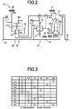
- Fig. 2 is a schematic for explaining an example of the torque converter 20 and the automatic transmission 22.
- the torque converter 20, the automatic transmission 22, etc. are configured substantially symmetrically with respect to an axial center RC of a transmission input shaft 34 that is an input rotating member of the automatic transmission 22 and have lower halves from the axial center RC not shown in Fig. 2 .
- the torque converter 20 is disposed in a power transmission path between the engine 12 and the automatic transmission 22 and is a fluid transmission device including a pump impeller 20p and a turbine impeller 20t.
- the pump impeller 20p is an input rotating member of the torque converter 20 and is coupled to a crankshaft 36 of the engine 12.
- the turbine impeller 20t is an output rotating member of the torque converter 20 and is coupled to a transmission input shaft 34.
- the transmission input shaft 34 also serves as a turbine shaft.
- the power transmission device 16 also includes a known lock-up clutch LC as a direct-coupling clutch coupling the pump impeller 20p and the turbine impeller 20t (i.e., coupling the input/output rotating members of the torque converter 20).
- the power transmission device 16 also includes a mechanical oil pump 38 coupled to the pump impeller 20p.
- the oil pump 38 is rotationally driven by the engine 12 to discharge hydraulic fluid used for a shift control of the automatic transmission 22, used for a switching control of an operation state of the lock-up clutch LC, and for supplying lubrication oil to portions of the power transmission device 16. Therefore, the hydraulic fluid pumped up by the oil pump 38 is supplied as a source pressure of a hydraulic control circuit 40 (see Fig. 1 ) included in the vehicle 10.
- the automatic transmission 22 is a multi-speed automatic transmission constituting a portion of the power transmission path between the engine 12 and the drive wheels 14.
- the automatic transmission 22 is a known planetary gear type automatic transmission including a plurality of planetary gear devices, i.e. a first planetary gear device 42, a second planetary gear device 44, and a third planetary gear device 46, as well as a plurality of engagement devices, i.e., a first clutch C1, a second clutch C2, a third clutch C3, a fourth clutch C4, a first brake B1, and a second brake B2 (hereinafter simply referred to as engagement devices CB if not particularly distinguished).
- engagement devices CB hereinafter simply referred to as engagement devices CB if not particularly distinguished.
- the engagement devices CB are hydraulic friction engagement devices made up of multiplate or single-plate type clutches and brakes pressed by hydraulic actuators, band brakes fastened by hydraulic actuators, etc.
- the engagement devices CB have respective torque capacities (clutch torques) Tcb (i.e., clutch torques Tc1, Tc2, Tc3, Tc4, Tb1, Tb2) changed in accordance with regulated hydraulic pressures (clutch pressures) Pcb (i.e., clutch pressures Pc1, Pc2, Pc3, Pc4, Pb1, Pb2) output respectively from solenoid valves SL1 to SL6 etc. in the hydraulic control circuit 40, so that respective operation states (states such as engagement and release) are switched.
- each of the engagement devices CB needs to have the clutch torque Tcb capable of providing a transmission torque amount that must be assigned thereto (i.e., a shared torque of the engagement device CB) with respect to the torque.
- the clutch torque Tcb capable of providing the transmission torque amount the transmission torque does not increase even if the clutch torque Tcb is increased.
- the clutch torque Tcb and the clutch pressure Pcb may synonymously be used for convenience.
- rotating elements (a first sun gear S1, a first carrier CA1, a first ring gear R1, a second sun gear S2, a third sun gear S3, a carrier RCA, a ring gear RR) of the plurality of the planetary gear devices are partly coupled to each other, or coupled to the transmission input shaft 34, the case 18, or the transmission output gear 24, directly or indirectly (or selectively) via the engagement devices CB.
- the carriers are made up of the common carrier RCA and the ring gears are made up of the common ring gear RR such that a so-called Ravigneaux type is achieved.
- gear ratio speed change ratio
- ⁇ gear ratio
- the automatic transmission 22 has eight forward gear positions from a first speed gear position "1st” to an eighth speed gear position "8th” and a reverse gear position "Rev” such that the gear positions are selectively established.
- the automatic transmission 22 is brought into a neutral state in which no gear position is established (i.e., a neutral state in which power transmission is interrupted).
- the gear ratio ⁇ is the highest at the first speed gear position "lst” and decreases toward the higher vehicle speed side (the eighth speed gear position "8th” side).
- the engagement operation table of Fig. 3 represents the relationship between the gear positions established in the automatic transmission 22 and the operation states of the engagement devices CB, and "O" and a blank indicate engagement and release of the engagement devices CB, respectively.
- the AT input rotation speed coin is rotation speed (angular speed) of the transmission input shaft 34 and the AT output rotation speed ⁇ o is rotation speed of the transmission output gear 24.
- the gear position to be established is switched (i.e. each of the gear positions is selectively achieved) by controlling the release of a release-side engagement device out of the engagement devices CB and the engagement of an engagement-side engagement device out of the engagement devices CB by the electronic control device 70 described later in accordance with a driver's accelerator operation, a vehicle speed V, etc.
- the electronic control device 70 performs a so-called clutch-to-clutch shift making a change in engagement of the engagement devices involved in the shift of the automatic transmission 22 (i.e., switching the engagement and release of the engagement devices CB), for example.
- the release-side engagement device is an engagement device to be released out of the engagement devices CB changed in engagement at the time of the shift
- the engagement-side engagement device is an engagement device to be engaged out of the engagement devices CB changed in engagement at the time of the shift.
- the first brake B1 serving as the release-side engagement device is released and the second brake B2 serving as the engagement-side engagement device is engaged.
- a release transition hydraulic pressure of the first brake B1 and an engagement transition hydraulic pressure of the second brake B2 are subjected to pressure-regulation control.
- the vehicle 10 includes the electronic control device 70 including a control device of the vehicle 10 related to the shift control of the automatic transmission 22, for example.
- the electronic control device 70 includes a so-called microcomputer including a CPU, a RAM, a ROM, and an I/O interface, for example, and the CPU executes signal processes in accordance with a program stored in advance in the ROM, while utilizing a temporary storage function of the RAM, to provide various controls of the vehicle 10.
- the electronic control device 70 provides the output control of the engine 12, the shift control of the automatic transmission 22, etc., and is configured separately for the engine output control, the hydraulic control (the shift control), etc., as needed.
- the electronic control device 70 is supplied with various signals (e.g., an engine rotation speed ⁇ e that is rotation speed of the engine 12, the AT input rotation speed coin that is also rotation speed of the turbine shaft (i.e., a turbine rotation speed ⁇ t), the AT output rotation speed ⁇ o corresponding to the vehicle speed V, the accelerator opening degree ⁇ acc that is an operation amount of an accelerator pedal, a throttle valve opening degree ⁇ th that is an opening degree of a throttle valve included in the electronic throttle device, a brake-on Bon representative of a brake operation state when a driver operates a brake operation member for operating a wheel brake, an operation position POSsh of a shift lever 68 serving as a shift operation member included in the vehicle 10, a mode-on MODEon representative of an operation of a driving mode selecting switch 64, and a hydraulic fluid temperature THoil that is a temperature of hydraulic fluid in the hydraulic control circuit 40) based on detection values from various sensors etc.
- various signals e.g., an engine rotation speed ⁇ e that is rotation speed of
- the electronic control device 70 supplies various devices included in the vehicle 10 (e.g., the engine control device 32 and the hydraulic control circuit 40) with various command signals (e.g., an engine control command signal Se and a hydraulic control command signal Sat).
- This hydraulic control command signal Sat is a command signal (instruction pressure) for driving the solenoid valves SL1 to SL6 regulating the clutch pressures Pcb supplied to the hydraulic actuators of the engagement devices CB and is output to the hydraulic control circuit 40.
- the operation position POSsh of the shift lever 68 includes, for example, P-, R-, N-, D-, and M-operation positions.
- the P-operation position is a parking operation position for selecting a parking position of the automatic transmission 22 at which the automatic transmission 22 is put into the neutral state while the rotation of the transmission output gear 24 is mechanically blocked (locked).
- the R-operation position is a backward-running operation position for selecting backward-running position of the automatic transmission 22 allowing the vehicle 10 to run backward.
- the N-operation position is a neutral operation position for selecting a neutral position of the automatic transmission 22 at which the automatic transmission 22 is put into the neutral state.
- the D-operation position is a forward-running operation position for selecting a forward-running position of the automatic transmission 22 at which an automatic shift control is provided among all the forward running gear positions of the automatic transmission 22 to allow the vehicle to run forward.
- the M-operation position is a manual shift operation position enabling a manual shift for switching the gear position of the automatic transmission 22 according to a driver's operation.
- This M-operation position includes an upshift operation position "+" for upshifting each time the shift lever 68 is operated, and a downshift operation position "-" for downshifting each time the shift lever 68 is operated.
- the driving mode selecting switch 64 is an operation member enabling the driver to select vehicle running in a desired driving mode.
- the driving mode includes, for example, a predefined normal mode for running such that the driver can drive in a favorable fuel consumption state while an engine performance is achieved, a predefined sport mode (or power mode) for running such that the driver can drive in a state in which the engine performance is prioritized over fuel efficiency in comparison with the normal mode, a predefined eco-mode for running such that the driver can drive in a state in which the fuel efficiency is prioritized over the engine performance in comparison with the normal mode.
- the electronic control device 70 includes an engine control means, i.e., an engine control portion 72, and a shift control means, i.e., a shift control portion 74.
- the engine control portion 72 controls the engine 12 such that a required value of the engine torque Te (hereinafter referred to as a required engine torque Tedem) is acquired.
- a required engine torque Tedem a required value of the engine torque Te
- the engine control portion 72 applies the accelerator opening degree ⁇ acc and the vehicle speed V (synonymous with the AT output rotation speed ⁇ o etc.) to a relationship (e.g., a drive torque map) obtained empirically or through design and stored in advance (i.e., predefined) to calculate a required drive torque Tdem.
- the engine control portion 72 outputs to the engine control device 32 the engine control command signal Se for acquiring the engine torque Te at which the required drive torque Tdem is achieved.
- the engine control portion 72 outputs to the engine control device 32 the engine control command signal Se for performing a fuel cut (also referred to as F/C) etc. for stopping a fuel supply to the engine 12 and thereby provides a fuel cut control to stop the operation of the engine 12.
- the stop of the engine 12 in this case is the stop of operation of the engine 12 and is not necessarily identical to the stop of rotation of the engine 12.
- the shift control portion 74 provides the shift control of the automatic transmission 22. For example, when the operation position POSsh is the D-operation position, the shift control portion 74 establishes the automatic shift mode, and makes determination on a shift of the automatic transmission 22 by using a predetermined relationship (e.g., a shift map) and outputs to the hydraulic control circuit 40 the hydraulic control command signal Sat for switching the operation state of the engagement devices CB so as to automatically switch the gear position of the automatic transmission 22 as needed.
- a predetermined relationship e.g., a shift map
- the shift control portion 74 establishes the manual shift mode, and outputs to the hydraulic control circuit 40 the hydraulic control command signal Sat for switching the operation state of the engagement devices CB so as to switch the gear position of the automatic transmission 22 in accordance with the shift operation of the shift lever 68 by the driver without depending on the shift map.
- the shift map is a predetermined relationship having shift lines (upshift and downshift lines) for determining the shift of the automatic transmission 22 on two-dimensional coordinates having the AT output rotation speed ⁇ o (in this case, synonymous with the vehicle speed V etc.) and the accelerator opening degree ⁇ acc (in this case, synonymous with the required drive torque Tdem, the throttle valve opening degree ⁇ th, etc.) as variables.
- the hydraulic control command signal Sat is a release-side instruction pressure for acquiring the clutch torque Tcb of the release-side engagement device (also referred to as a release-side clutch torque Tcbdrn) at the time of the shift and an engagement-side instruction pressure for acquiring the clutch torque Tcb of the engagement-side engagement device (also referred to as an engagement-side clutch torque Tcbapl) at the time of the shift, for example.
- the shift control portion 74 performs the shift of the automatic transmission 22 by using a predefined shift model for determining control operation amounts achieving shift target values.
- the shift target values are target values of items (e.g., a shift time, a drive force) defining a form of change desired to be achieved at the time of the shift.
- the item capable of expressing the shift time is, for example, a time derivative, i.e., a time change rate, of the AT input rotation speed ⁇ in or, in other words, an angular acceleration defined as a speed change amount of the transmission input shaft 34 (hereinafter referred to as an input shaft angular acceleration d ⁇ in/dt).
- the item capable of expressing the drive force is, for example, a torque at the transmission output gear 24 (hereinafter referred to as an AT output torque To).
- the shift target values are set as a target value of the input shaft angular acceleration d ⁇ in/dt (hereinafter referred to as a target input shaft angular acceleration d ⁇ intgt/dt) and a target value of the AT output torque To (hereinafter referred to as a target AT output torque Totgt).
- the control operation amounts are items (such as the engine torque Te and the clutch torque Tcb) operated for a control object.
- Equations (1) and (2) are gear train motion equations of the automatic transmission 22 including the shift target values and the control operation amounts and acquired by formulating a relationship of the shift target values and the control operation amounts. Equations (1) and (2) are derived from respective motion equations of the mutually-connected rotating elements constituting the automatic transmission 22 and relational expressions in the planetary gear devices 42, 44, 46 constituting the automatic transmission 22, respectively.
- the respective motion equations of the rotating elements are motion equations defining with torque at the rotating elements in terms of respective torque acting on each of the three members (the sun gear, the carrier, and the ring gear) of the planetary gear devices 42, 44, 46 and member(s) involved with the respective rotating elements out of the members on both sides of the engagement devices CB, and the torque is represented by the product of the inertia and the angular acceleration at the rotating elements or the member.
- the relational expressions in the planetary gear devices 42, 44, 46 are relational expressions respectively defining a relationship of torque and a relationship of angular accelerations in the three members of the planetary gear devices 42, 44, 46 using the gear ratios ⁇ 1, ⁇ 2, ⁇ 3 of the planetary gear devices 42, 44, 46.
- Equations (1) and (2) an angular acceleration d ⁇ /dt is indicated by the angular velocity ⁇ with a dot superposed thereon. It is noted that d ⁇ o/dt is a temporal change rate of the AT output rotation speed ⁇ o and represents an angular acceleration (output gear angular acceleration) of the transmission output gear 24.
- Constants a1, a2, b1, b2, c1, c2, d1, d2 are coefficients defined in design from the inertia in the rotating elements and the gear ratios ⁇ 1, ⁇ 2, ⁇ 3 of the planetary gear devices 42, 44, 46 (specific numerical values differ depending on the shift patterns such as a power-on upshift, a power-off upshift, a power-on downshift, or a power-off downshift, gear positions between which the shift is performed, etc.).
- ⁇ ⁇ intgt a 1 ⁇ Tin + b 1 ⁇ Tcbapl + c 1 ⁇ Tcbdrn + d 1 ⁇ ⁇ ⁇ o
- Togtg a 2 ⁇ Tin + b 2 ⁇ Tcbapl + c 2 ⁇ Tcbdrn + d 2 ⁇ ⁇ ⁇ o
- the shift model of this example uses the motion equation of the automatic transmission 22 including the shift target values and the control operation amounts and the condition necessary for determining the control operation amounts with the shift model to determine the control operation amounts achieving the shift target values.
- the electronic control device 70 further includes a shift target value setting means, i.e., a shift target value setting portion 76, a condition setting means, i.e., a condition setting portion 78, and a control operation amount calculating means, i.e., a control operation amount calculating portion 80.
- a shift target value setting means i.e., a shift target value setting portion 76
- a condition setting means i.e., a condition setting portion 78
- a control operation amount calculating means i.e., a control operation amount calculating portion 80.
- the shift target value setting portion 76 sets the target input shaft angular acceleration d ⁇ intgt/dt in transition state of the shift using, for example, a relationship (e.g. input shaft angular acceleration map) in which the input shaft angular acceleration d ⁇ in/dt is defined in advance such that the change in the AT input rotation speed ⁇ in in an inertia phase satisfying both the suppression of a shift shock and the shift time.
- a relationship e.g. input shaft angular acceleration map
- the shift target value setting portion 76 sets the target AT output torque Totgt in transition of the shift by using, for example, a relationship (transmission output torque change map) in which a form of changing the AT output torque To is defined in advance, based on the required drive torque Tdem calculated by the engine control portion 72 and an elapsed time from the start of the shift control.
- a relationship transmission output torque change map
- the condition setting portion 78 sets a condition (also referred to as a constraint condition) necessary for determining the control operation amounts with the shift model.
- the constraint condition is, for example, a torque sharing ratio of a transmission torque assigned to the release-side engagement device and the engagement-side engagement device.
- the torque sharing ratio is the ratio of the transmission torque shared by each of both engagement devices with respect to the torque on the transmission input shaft 34 when a total of transmission torque (total transmission torque) to be assigned to the release-side engagement device and the engagement-side engagement device at the time of the shift of the automatic transmission 22 is converted into the torque on the transmission input shaft 34, for example.
- the form of changing the torque sharing ratio is defined in advance for each shift pattern or gear positions between which the shift is performed, for example.
- the AT input torque Tin can be prevented from changing from the value before the shift, the release-side clutch torque Tcbdrn can be set to zero, or the engagement-side clutch torque Tcbapl can be set to zero.
- the constraint condition includes, for example, fixing the value of the release-side clutch torque Tcbdrn (e.g., setting the release-side clutch torque Tcbdrn to zero or setting the constant of the term of the release-side clutch torque Tcbdm to zero in the motion equation), fixing the value of the engagement-side clutch torque Tcbapl, or fixing the value of the AT input torque Tin, etc.
- the control operation amount calculating portion 80 calculates the AT input torque Tin, the release-side clutch torque Tcbdrn, and the engagement-side clutch torque Tcbapl as the control operation amounts in accordance with the shift model for determining the control operation amount achieving the shift target values (i.e., the target input shaft angular acceleration d ⁇ intgt/dt and the target AT output torque Totgt set by the shift target value setting portion 76).
- the control operation amount calculating portion 80 transmits the AT input torque Tin, the release-side clutch torque Tcbdrn, and the engagement-side clutch torque Tcbapl as the required values for performing the shift (referred to as a required AT input torque Tindem, a required release-side clutch torque Tcbdrndern, and a required engagement-side clutch torque Tcbapldem, respectively) to the engine control portion 72 and the shift control portion 74.
- the engine control portion 72 outputs to the engine control device 32 the engine control command signal Se for acquiring the required AT input torque Tindem (synonymous with the required engine torque Tedem) transmitted from the control operation amount calculating portion 80.
- the shift control portion 74 outputs to the hydraulic control circuit 40 the hydraulic control command signal Sat for acquiring the required release-side clutch torque Tcbdrndem and the required engagement-side clutch torque Tcbapldem transmitted from the control operation amount calculating portion 80.
- the downshift to be described is a downshift requested through an operation of the shift lever 68 at the time of accelerator-off, a downshift performed in association with accelerator-off state when the sport mode is selected with the driving mode selecting switch 64, or a downshift performed in association with the brake-on Bon at the time of accelerator-off.
- the electronic control device 70 performs a so-called blipping downshift in which the shift is allowed to promptly proceed by performing an engine torque-up to raise the engine torque Te in a shift transition process.
- the condition setting portion 78 sets the constraint condition in the shift model such that the blipping downshift as described above is performed during the downshift performed during deceleration running associated with accelerator-off state.
- the constraint condition at the time of the blipping downshift is set to, for example, a condition under which only the release-side engagement device is engaged between the release-side engagement device and engagement-side engagement device (e.g., condition under which the term of the engagement-side clutch torque Tcbapl is set to zero in the motion equation) when the torque phase is in progress, or a condition under which the release-side engagement device is released (e.g., condition under which the term of the release-side clutch torque Tcbdrn is set to zero in the motion equation) when the inertia phase is in progress.
- a condition under which only the release-side engagement device is engaged between the release-side engagement device and engagement-side engagement device e.g., condition under which the term of the engagement-side clutch torque Tcbapl is set to zero in
- the shift target value setting portion 76 sets the target AT output torque Totgt in transition of the shift such that the torque is changed from the AT output torque To before downshift to the AT output torque To after downshift.
- the AT output torque To during deceleration running associated with accelerator-off is a negative torque (also referred to as a deceleration torque) acquired due to an engine brake torque from the engine 12 during the fuel cut control, for example. This deceleration torque is changed depending on the gear position of the automatic transmission 22, and is more increased at the gear position on the lower vehicle speed side (i.e., the AT output torque To is reduced within the range of zero or less).
- Fig. 6 is a time chart in the case of performing the blipping downshift and is a diagram of a comparative example different from this example.
- a region A indicated by hatched lines in a chart of the required AT input torque Tindem is a region corresponding to the engine torque Te achieved by the engine 12 during the fuel cut control.
- this region A since the engine torque Te is passively determined due to a friction of the engine 12, a load of accessories such as an alternator, etc., this region A is a region in which the engine torque Te is difficult to be controlled.
- An upper limit boundary line L of this region A indicates the AT input torque Tin corresponding to a minimum torque of the engine torque Te in the engine 12 when the fuel cut control is canceled (also referred to as a minimum AT input torque Tinlow).
- This region of the minimum AT input torque Tinlow or more is a region in which the engine torque Te is controllable.
- the target AT output torque Totgt is changed during the torque phase such that the torque decreases from the AT output torque To before downshift (n-speed output torque) toward the AT output torque To after downshift (n-1-speed output torque).
- the required AT input torque Tindem is set to a value within the region A until the start of the inertia phase and is raised after the start of the inertia phase from within the region A into the region of the minimum AT input torque Tinlow or more.
- the engine torque Te is the uncontrolled passive engine torque Te, and substantially no engine torque-up is performed.
- the required AT input torque Tindem is made equal to or greater than the minimum AT input torque Tinlow, the fuel cut control is canceled and the engine torque-up becomes possible.
- an increment of the engine torque Te i.e., an engine torque-up amount
- an engine torque-up amount contributes as a torque amount allowing the downshift to proceed during the inertia phase. Therefore, the actual engine torque-up amount is insufficient with respect to the engine torque-up amount corresponding to the increment of the required AT input torque Tindem during the inertia phase. As a result, the progress of the downshift may stagnate due to a shortage of the engine torque-up amount.
- the start of the inertia phase may be delayed due to the shortage of the engine torque-up amount. It is conceivable that because of the stagnation of the progress of the downshift, the AT input rotation speed ⁇ in is forcibly raised toward the synchronous rotation speed after downshift at the engagement-side engagement device regardless of the engagement-side clutch torque Tcbapl calculated by using the motion equations of Equations (1) and (2), for example. This may lead to a deterioration in shift feeling and an increase in shift shock.
- the shift target value setting portion 76 sets the target AT output torque Totgt in transition state of the shift such that the torque varies once directed in an increasing direction opposite to the direction of decreasing toward the AT output torque To at the completion of the downshift, in the process of changing the target AT output torque Totgt from the AT output torque To before downshift to the AT output torque To after downshift.
- the target AT output torque Totgt is set to a value larger than the minimum AT output torque Tolow before the start of the inertia phase, or to increase the target AT output torque Totgt from the AT output torque To before downshift to a value larger than the minimum AT output torque Tolow during the torque phase. Since the deceleration running is being performed, it is preferable to increase the target AT output torque Totgt in the range of zero or less, or to apply an upper limit guard to the target AT output torque Totgt at zero value, so as to prevent the feeling of deceleration from deteriorating.
- the shift target value setting portion 76 reduces the target AT output torque Totgt toward the AT output torque To after downshift.
- the predetermined rotation speed is a predefined threshold value at which it can be determined that the AT input rotation speed coin has approached the synchronous rotation speed after downshift to the extent that the target AT output torque Totgt no longer needs to be maintained at a value larger than the minimum AT output torque Tolow.
- the shift target value setting portion 76 sets the target AT output torque Totgt such that after being increased from the AT output torque To before downshift within the range of zero or less, the torque Totgt is reduced toward the AT output torque To after downshift when the AT input rotation speed coin approaches the synchronous rotation speed after downshift.
- the shift target value setting portion 76 increases the target AT output torque Totgt in a period from the start of the shift control to the start of the inertia phase in the downshift.
- the shift target value setting portion 76 increases the target AT output torque Totgt toward a value larger than the minimum AT output torque Tolow.
- Fig. 4 is a flowchart for explaining a main portion of the control operation of the electronic control device 70, i.e., the control operation for suppressing the stagnation of the shift due to the shortage of the engine torque-up amount when a downshift is performed during deceleration running associated with accelerator-off by using the shift model and is repeatedly executed during the blipping downshift, for example.
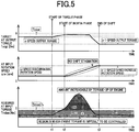
- Fig. 5 is a diagram of an example of a time chart when the control operation shown in the flowchart of Fig. 4 is performed.
- the target AT output torque Totgt is set such that after being increased from the AT output torque To before downshift within the range of zero or less, the torque Totgt is reduced toward the AT output torque To after downshift when the AT input rotation speed coin approaches the synchronous rotation speed after downshift.
- the control operation amounts achieving the shift target values set at S10 are calculated by using the motion equations of Equations (1) and (2) and the constraint condition, and the control operation amounts are set as required values (the required AT input torque Tindem, the required release-side clutch torque Tcbdmdem, the required engagement-side clutch torque Tcbapldem) for performing the shift.
- the engine control command signal Se for acquiring the required AT input torque Tindem (synonymous with the required engine torque Tedem) set at S20 is output to the engine control device 32, and the hydraulic control command signal Sat for acquiring the required release-side clutch torque Tcbdrndern and the required engagement-side clutch torque Tcbapldem set at S20 is output to the hydraulic control circuit 40.
- a region A indicated by hatched lines in a chart of the required AT input torque Tindem is a region corresponding to the engine torque Te during the fuel cut control.
- an upper limit boundary line L of this region A indicates the minimum AT input torque Tinlow.
- the target AT output torque Totgt is increased from the AT output torque To before downshift (n-speed output torque) to a value larger than the minimum AT output torque Tolow during the torque phase (see time t1 to time t2).
- the target AT output torque Totgt is maintained at a value larger than the minimum AT output torque Tolow until the AT input rotation speed coin approaches the synchronous rotation speed after downshift (n-1-speed synchronous rotation speed), and is then reduced toward the AT output torque To after downshift (n-1-speed output torque) (see time t2 to time t3).
- the target AT output torque Totgt By setting the target AT output torque Totgt in this way, the engine torque-up can be performed immediately after the start of the inertia phase. Therefore, the shortage of the engine torque-up amount can be avoided or suppressed in a region B indicated by shading in the chart of the required AT input torque Tindem with respect to the engine torque-up amount corresponding to the increment of the required AT input torque Tindem during the inertia phase. As a result, the progress of the downshift does not stagnate or is restrained from stagnating.
- the target AT output torque Totgt is set such that after being increased within the range of zero or less, the torque is reduced toward the AT output torque To after downshift and, therefore, the required engine torque Tedem is increased as the target AT output torque Totgt is once increased, so that an increment of the engine torque Te is easily ensured when the engine torque Te is raised with the release-side engagement device released.
- the shift can be restrained from stagnating due to the shortage of the increment of the engine torque Te. Since the target AT output torque Totgt is increased within the range of zero or less, the feeling of deceleration can be restrained from deteriorating.
- the target AT output torque Totgt is increased in the period from the start of the shift control to the start of the inertia phase in the downshift, the increment of the engine torque Te in the inertia phase is easily ensured and the stagnation of the shift can appropriately be suppressed.
- the target AT output torque Totgt is increased toward a value larger than the minimum AT output torque Tolow, the increment of the engine torque Te is more easily ensured when the engine torque Te is raised with the release-side engagement device released.
- control operation amounts are calculated according to the shift model for determining the control operation amounts achieving the shift target values by using the motion equation of the automatic transmission 22 and the constraint condition, the control operation amounts can appropriately be calculated when the downshift is performed during deceleration running associated with accelerator-off.
- the M-operation position is one of the operation positions POSsh of the shift lever 68 and is a manual shift operation position enabling a manual shift for switching the gear position of the automatic transmission 22 according to an operation of the shift lever 68 by a driver; however, this form is not necessary.
- the M-operation position may be a manual shift operation position at which a manual shift can be performed within a plurality of shift ranges which are different in their highest gear positions to be shifted in the automatic transmission 22.
- the vehicle 10 may further include a paddle switch (not shown) as a gear position switching operation member enabling a shift operation equivalent to the operation of the shift lever 68 to the upshift operation position "+" or the downshift operation position "-" at the M-operation position.
- the paddle switch may be mounted on a steering wheel and is provided with an upshift switch and a downshift switch.
- the driver can operate the upshift switch and the downshift switch and the shift operation equivalent to that with the shift lever 68 can be performed, while the driver grips the steering wheel.
- the electronic control device 70 performs the blipping downshift.
- the vehicle may not necessarily be a vehicle in which the manual shift mode is established.
- the present invention is not limited to this form.
- another fluid transmission device such as a fluid coupling without a torque amplification effect may be used instead of the torque converter 20.
- this fluid transmission device may not necessarily be provided in the vehicle.
Landscapes
- Engineering & Computer Science (AREA)
- General Engineering & Computer Science (AREA)
- Mechanical Engineering (AREA)
- Chemical & Material Sciences (AREA)
- Combustion & Propulsion (AREA)
- Transportation (AREA)
- Physics & Mathematics (AREA)
- Fluid Mechanics (AREA)
- Automation & Control Theory (AREA)
- Control Of Transmission Device (AREA)
- Control Of Driving Devices And Active Controlling Of Vehicle (AREA)
Description
- The present invention relates to a control device of a vehicle performing a shift of a multi-speed transmission.
- In a vehicle including a multi-speed transmission having gear positions switched by controlling release of a release-side engagement device out of a plurality of engagement devices and engagement of an engagement-side engagement device out of the plurality of engagement devices, and an engine having a power transmitted through the multi-speed transmission to drive wheels, a control device of the vehicle is well known that performs a shift of the multi-speed transmission by using a predefined shift model for determining control operation amounts achieving shift target values. For example, this corresponds to the shift control device of a vehicle described in
Patent Document 1 with all the features of the preamble ofclaim 1. It is disclosed inPatent Document 1 that a shift of the automatic transmission is performed according to a shift model for calculating the control operation amounts based on the shift target values by using a motion equation of an automatic transmission including target values of a transmission output torque and an input shaft angular acceleration as the shift target values as well as a transmission input torque, a torque capacity of the engagement-side engagement device, and a torque capacity of the release-side engagement device as the control operation amounts, and a relationship representative of a torque sharing ratio of transmission torques assigned to the engagement-side engagement device and the release-side engagement device at the time of the shift. - Patent Document 1:
WO 2014/020685A1 - At the time of a downshift performed during deceleration running associated with accelerator-off, it is conceivable that by raising an output torque of the engine (also referred to as an engine torque) with the release-side engagement device released, a rotation speed of an input rotating member of the multi-speed transmission is increased toward a synchronous rotation speed after the downshift to allow the shift to proceed before the engagement-side engagement device is engaged. On the other hand, the torque at the input rotating member of the multi-speed transmission determined by using the shift model is achieved by controlling the engine torque. If a fuel cut control is provided in the engine during decelerating running associated with accelerator-off, the engine torque is determined by a rotational resistance etc. of the engine and it is difficult to control the engine torque to a desired value. Cancelation of the fuel cut control makes the engine torque controllable to a desired value. When the downshift as described above is performed by using a shift model, a required value of the engine torque determined using the shift model is increased from a region in which the engine torque is difficult to be controlled into a region in which the engine torque is controllable in some cases. In such a case, since the actual engine torque is increased through the control from when the required value of the engine torque enters the controllable region of the engine torque, a torque amount exclusively contributing to the progress of the down shift is only an amount of torque increased while the required value of the engine torque is within the controllable region of the engine torque. Therefore, in the case of the downshift as described above, the downshift may hardly proceed due to an insufficient increment of the actual engine torque.
- The present invention was conceived in view of the situations and it is therefore an object of the present invention to provide a control device of a vehicle capable of suppressing stagnation of a shift due to an insufficiency increment of engine torque when a downshift during deceleration running associated with accelerator-off is performed by using a shift model.
- The object indicated above is achieved according to a first aspect of the present invention, which provides a control device of a vehicle including a multi-speed transmission having gear positions switched by executing release of a release-side engagement device out of a plurality of engagement devices and engagement of an engagement-side engagement device out of the plurality of engagement devices, and an engine of which a power is transmitted through the multi-speed transmission to drive wheels, the control device being configured to perform a shift of the multi-speed transmission by using a predefined shift model for determining control operation amounts of a torque at an input rotating member of the multi-speed transmission, a torque capacity of the release-side engagement device, and a torque capacity of the engagement-side engagement device, the control operation amounts achieving shift target values that are a target value of a torque at an output rotating member of the multi-speed transmission and a target value of angular acceleration of the input rotating member of the multi-speed transmission, the control device comprising: a condition setting portion setting a condition necessary for determining the control operation amounts using the shift model such that during a downshift performed during deceleration running associated with accelerator-off state, an output torque of the engine is raised with the release-side engagement device released so as to increase a rotation speed of the input rotating member of the multi-speed transmission toward a synchronous rotation speed after the downshift and such that the engagement-side engagement device is then engaged; and a shift target value setting portion setting the target value of the torque at the output rotating member of the multi-speed transmission during the downshift such that the torque at the output rotating member of the multi-speed transmission is increased from a value of the torque at the output rotating member before the downshift within a range of zero or less, and when a rotation speed of the input rotating member of the multi-speed transmission approaches the synchronous rotation speed after the downshift, the target value is reduced toward a torque at the output rotating member after the downshift.
- A second aspect of the present invention provides the control device of a vehicle of the present invention, wherein the shift target value setting portion is configured to increase the target value of the torque at the output rotating member of the multi-speed transmission in a period from a start of a shift control to a start of an inertia phase in the downshift.
- A third aspect of the present invention provides the control device of a vehicle of the present invention, further comprising an engine control portion providing a fuel cut control of the engine during the deceleration running associated with the accelerator-off state, wherein the shift target value setting portion is configured to increase the target value of the torque at the output rotating member of the multi-speed transmission toward a value larger than a value acquired by multiplying a torque at the input rotating member of the multi-speed transmission corresponding to a minimum torque of the output torque of the engine at the time of cancelation of the fuel cut control by a gear ratio of the multi-speed transmission after the downshift.
- A fourth aspect of the present invention provides the control device of a vehicle of the present invention, further comprising a control operation amount calculating portion calculating the control operation amounts in accordance with the shift model for determining the control operation amounts achieving the shift target values, by using a motion equation of the multi-speed transmission including the shift target values and the control operation amounts as well as the condition necessary for determining the control operation amounts with the shift model.
- According to the first aspect of the invention, during the downshift during deceleration running associated with accelerator-off state performed by using the shift model, the target value of the torque at the output rotating member of the multi-speed transmission is set such that after being increased within the range of zero or less, the target value is reduced toward the torque at the output rotating member after downshift and, therefore, the required value of the engine torque is increased as the target value of the torque at the output rotating member of the multi-speed transmission is once increased, so that an increment of the engine torque is easily ensured when the engine torque is raised with the release-side engagement device released. Thus, when the downshift during deceleration running associated with accelerator-off is performed by using the shift model, the shift can be restrained from stagnating due to the shortage of the increment of the engine torque.
- According to the second aspect of the invention, since the target value of the torque at the output rotating member of the multi-speed transmission is increased in the period from the start of the shift control to the start of the inertia phase in the downshift, the increment of the engine torque in the inertia phase is easily ensured and the stagnation of the shift can appropriately be suppressed.
- According to the third aspect of the invention, since the target value of the torque at the output rotating member of the multi-speed transmission is increased toward the value larger than the value acquired by multiplying the torque at the input rotating member of the multi-speed transmission corresponding to the minimum torque of the engine torque at the time of cancelation of the fuel cut control by the gear ratio of the multi-speed transmission after the downshift, the increment of the engine torque is more easily ensured when the engine torque is raised with the release-side engagement device released.
- According to the fourth aspect of the invention, since the control operation amounts are calculated according to the shift model for determining the control operation amounts achieving the shift target values by using the motion equation of the multi-speed transmission including the shift target values and the control operation amounts as well as the condition necessary for determining the control operation amounts with the shift model, the control operation amounts can appropriately be calculated when the downshift is performed during deceleration running associated with accelerator-off.
-
-
Fig. 1 is a diagram for explaining a general configuration of a vehicle to which the present invention is applied and is a diagram for explaining main portions of a control function and a control system for various controls in the vehicle. -
Fig. 2 is a schematic for explaining an example of a torque converter and an automatic transmission. -
Fig. 3 is an operation chart for explaining a relationship between a shift operation of the automatic transmission and a combination of operations of engagement devices used therefor. -
Fig. 4 is a flowchart for explaining a main portion of the control operation of an electronic control device, i.e., the control operation for suppressing the stagnation of the shift due to a shortage of an engine torque-up amount when a downshift is performed during deceleration running associated with accelerator-off by using a shift model. -
Fig. 5 is a diagram of an example of a time chart when the control operation shown in the flowchart ofFig. 4 is performed. -
Fig. 6 is a time chart in the case of performing a blipping downshift and is a diagram of a comparative example different from this example. - In an embodiment of the present invention, the multi-speed transmission is an automatic transmission in which a plurality of gear positions different in gear ratio is selectively established. The automatic transmission is, for example, a known planetary gear type automatic transmission, or a synchronous meshing type parallel two-shaft automatic transmission known as a DCT (Dual Clutch Transmission) that is a type of automatic transmission including two systems of input shafts each connected to engagement devices respectively and further respectively connected to gears corresponding to the even positions and the odd positions. In the case of DCT, the plurality of engagement devices corresponds to the engagement devices respectively connected to the input shafts of the two systems.
- The engine is an internal combustion engine such as a gasoline engine or a diesel engine combusting fuel to generate power, for example. Although the vehicle may include at least the engine as a power source, another motor such as an electric motor may also be included along with the engine.
- An example of the present invention will now be described in detail with reference to the drawings.
-
Fig. 1 is a diagram for explaining a general configuration of avehicle 10 to which the present invention is applied and is a diagram for explaining main portions of a control function and a control system for various controls in thevehicle 10. InFig. 1 , thevehicle 10 includes anengine 12,drive wheels 14, and apower transmission device 16 disposed in a power transmission path between theengine 12 and thedrive wheels 14. Thepower transmission device 16 includes, in acase 18 acting as a non-rotating member attached to a vehicle body, atorque converter 20, anautomatic transmission 22, areduction gear mechanism 26 coupled to atransmission output gear 24 that is an output rotating member of theautomatic transmission 22, adifferential gear 28 coupled to thereduction gear mechanism 26, etc. Thepower transmission device 16 also includes a pair ofdrive shafts 30 etc. coupled to thedifferential gear 28. In thepower transmission device 16, the power (synonymous with torque and force if not particularly distinguished) output from theengine 12 is transmitted sequentially through thetorque converter 20, theautomatic transmission 22, thereduction gear mechanism 26, thedifferential gear 28, thedrive shaft 30, etc. to thedriving wheels 14. - The
engine 12 is a drive force source of thevehicle 10 and includes anengine control device 32 having various devices necessary for an output control of theengine 12, such as an electronic throttle device, a fuel injection device, and an ignition device. In theengine 12, an output torque of the engine 12 (i.e., an engine torque Te) is controlled through control of theengine control device 32 depending on an accelerator opening degree θacc corresponding to a drive request amount from a driver to thevehicle 10 by anelectronic control device 70 described later. -
Fig. 2 is a schematic for explaining an example of thetorque converter 20 and theautomatic transmission 22. Thetorque converter 20, theautomatic transmission 22, etc. are configured substantially symmetrically with respect to an axial center RC of atransmission input shaft 34 that is an input rotating member of theautomatic transmission 22 and have lower halves from the axial center RC not shown inFig. 2 . - In
Fig. 2 , thetorque converter 20 is disposed in a power transmission path between theengine 12 and theautomatic transmission 22 and is a fluid transmission device including apump impeller 20p and aturbine impeller 20t. Thepump impeller 20p is an input rotating member of thetorque converter 20 and is coupled to acrankshaft 36 of theengine 12. Theturbine impeller 20t is an output rotating member of thetorque converter 20 and is coupled to atransmission input shaft 34. Thetransmission input shaft 34 also serves as a turbine shaft. Thepower transmission device 16 also includes a known lock-up clutch LC as a direct-coupling clutch coupling thepump impeller 20p and theturbine impeller 20t (i.e., coupling the input/output rotating members of the torque converter 20). Thepower transmission device 16 also includes amechanical oil pump 38 coupled to thepump impeller 20p. Theoil pump 38 is rotationally driven by theengine 12 to discharge hydraulic fluid used for a shift control of theautomatic transmission 22, used for a switching control of an operation state of the lock-up clutch LC, and for supplying lubrication oil to portions of thepower transmission device 16. Therefore, the hydraulic fluid pumped up by theoil pump 38 is supplied as a source pressure of a hydraulic control circuit 40 (seeFig. 1 ) included in thevehicle 10. - The
automatic transmission 22 is a multi-speed automatic transmission constituting a portion of the power transmission path between theengine 12 and thedrive wheels 14. Theautomatic transmission 22 is a known planetary gear type automatic transmission including a plurality of planetary gear devices, i.e. a firstplanetary gear device 42, a secondplanetary gear device 44, and a thirdplanetary gear device 46, as well as a plurality of engagement devices, i.e., a first clutch C1, a second clutch C2, a third clutch C3, a fourth clutch C4, a first brake B1, and a second brake B2 (hereinafter simply referred to as engagement devices CB if not particularly distinguished). - The engagement devices CB are hydraulic friction engagement devices made up of multiplate or single-plate type clutches and brakes pressed by hydraulic actuators, band brakes fastened by hydraulic actuators, etc. The engagement devices CB have respective torque capacities (clutch torques) Tcb (i.e., clutch torques Tc1, Tc2, Tc3, Tc4, Tb1, Tb2) changed in accordance with regulated hydraulic pressures (clutch pressures) Pcb (i.e., clutch pressures Pc1, Pc2, Pc3, Pc4, Pb1, Pb2) output respectively from solenoid valves SL1 to SL6 etc. in the
hydraulic control circuit 40, so that respective operation states (states such as engagement and release) are switched. To transmit a torque between thetransmission input shaft 34 and thetransmission output gear 24 without slipping the engagement devices CB (i.e., without generating a differential rotation speed in the engagement devices CB), each of the engagement devices CB needs to have the clutch torque Tcb capable of providing a transmission torque amount that must be assigned thereto (i.e., a shared torque of the engagement device CB) with respect to the torque. However, at the clutch torque Tcb capable of providing the transmission torque amount, the transmission torque does not increase even if the clutch torque Tcb is increased. In this example, the clutch torque Tcb and the clutch pressure Pcb may synonymously be used for convenience. - In the
automatic transmission 22, rotating elements (a first sun gear S1, a first carrier CA1, a first ring gear R1, a second sun gear S2, a third sun gear S3, a carrier RCA, a ring gear RR) of the plurality of the planetary gear devices are partly coupled to each other, or coupled to thetransmission input shaft 34, thecase 18, or thetransmission output gear 24, directly or indirectly (or selectively) via the engagement devices CB. In the secondplanetary gear device 44 and the thirdplanetary gear device 46, the carriers are made up of the common carrier RCA and the ring gears are made up of the common ring gear RR such that a so-called Ravigneaux type is achieved. - The
automatic transmission 22 has a plurality of gear positions (gear shift positions) different in gear ratio (speed change ratio) γ (=AT input rotation speed ωin/AT output rotation speed ωo) selectively established by selective engagement of the engagement devices CB. For example, as shown in an engagement operation table ofFig. 3 , theautomatic transmission 22 has eight forward gear positions from a first speed gear position "1st" to an eighth speed gear position "8th" and a reverse gear position "Rev" such that the gear positions are selectively established. When the engagement devices CB are all released, theautomatic transmission 22 is brought into a neutral state in which no gear position is established (i.e., a neutral state in which power transmission is interrupted). The gear ratio γ is the highest at the first speed gear position "lst" and decreases toward the higher vehicle speed side (the eighth speed gear position "8th" side). The engagement operation table ofFig. 3 represents the relationship between the gear positions established in theautomatic transmission 22 and the operation states of the engagement devices CB, and "O" and a blank indicate engagement and release of the engagement devices CB, respectively. The AT input rotation speed coin is rotation speed (angular speed) of thetransmission input shaft 34 and the AT output rotation speed ωo is rotation speed of thetransmission output gear 24. The gear ratio γ of theautomatic transmission 22 corresponding to each of the gear positions is appropriately defined by gear ratios (=the number of teeth of the sun gear/the number of teeth of the ring gear) ρ1, p2, and p3 of the firstplanetary gear device 42, the secondplanetary gear device 44, and the thirdplanetary gear device 46. - In the
automatic transmission 22, the gear position to be established is switched (i.e. each of the gear positions is selectively achieved) by controlling the release of a release-side engagement device out of the engagement devices CB and the engagement of an engagement-side engagement device out of the engagement devices CB by theelectronic control device 70 described later in accordance with a driver's accelerator operation, a vehicle speed V, etc. At the time of a shift of theautomatic transmission 22, theelectronic control device 70 performs a so-called clutch-to-clutch shift making a change in engagement of the engagement devices involved in the shift of the automatic transmission 22 (i.e., switching the engagement and release of the engagement devices CB), for example. The release-side engagement device is an engagement device to be released out of the engagement devices CB changed in engagement at the time of the shift, and the engagement-side engagement device is an engagement device to be engaged out of the engagement devices CB changed in engagement at the time of the shift. For example, in the downshift from the second speed gear position "2nd" to the first speed gear position "1st" (represented as 2→1 downshift), as shown in the engagement operation table ofFig. 3 , the first brake B1 serving as the release-side engagement device is released and the second brake B2 serving as the engagement-side engagement device is engaged. In this case, a release transition hydraulic pressure of the first brake B1 and an engagement transition hydraulic pressure of the second brake B2 are subjected to pressure-regulation control. - Returning to
Fig. 1 , thevehicle 10 includes theelectronic control device 70 including a control device of thevehicle 10 related to the shift control of theautomatic transmission 22, for example. Theelectronic control device 70 includes a so-called microcomputer including a CPU, a RAM, a ROM, and an I/O interface, for example, and the CPU executes signal processes in accordance with a program stored in advance in the ROM, while utilizing a temporary storage function of the RAM, to provide various controls of thevehicle 10. For example, theelectronic control device 70 provides the output control of theengine 12, the shift control of theautomatic transmission 22, etc., and is configured separately for the engine output control, the hydraulic control (the shift control), etc., as needed. - The electronic control device 70 is supplied with various signals (e.g., an engine rotation speed ωe that is rotation speed of the engine 12, the AT input rotation speed coin that is also rotation speed of the turbine shaft (i.e., a turbine rotation speed ωt), the AT output rotation speed ωo corresponding to the vehicle speed V, the accelerator opening degree θacc that is an operation amount of an accelerator pedal, a throttle valve opening degree θth that is an opening degree of a throttle valve included in the electronic throttle device, a brake-on Bon representative of a brake operation state when a driver operates a brake operation member for operating a wheel brake, an operation position POSsh of a shift lever 68 serving as a shift operation member included in the vehicle 10, a mode-on MODEon representative of an operation of a driving mode selecting switch 64, and a hydraulic fluid temperature THoil that is a temperature of hydraulic fluid in the hydraulic control circuit 40) based on detection values from various sensors etc. included in the vehicle 10 (e.g., an engine rotation speed sensor 50, an input rotation speed sensor 52, an output rotation speed sensor 54, an accelerator opening degree sensor 56, a throttle valve opening degree sensor 58, a brake switch 60, a shift position sensor 62, the driving mode selecting switch 64, and an oil temperature sensor 66). The
electronic control device 70 supplies various devices included in the vehicle 10 (e.g., theengine control device 32 and the hydraulic control circuit 40) with various command signals (e.g., an engine control command signal Se and a hydraulic control command signal Sat). This hydraulic control command signal Sat is a command signal (instruction pressure) for driving the solenoid valves SL1 to SL6 regulating the clutch pressures Pcb supplied to the hydraulic actuators of the engagement devices CB and is output to thehydraulic control circuit 40. - The operation position POSsh of the
shift lever 68 includes, for example, P-, R-, N-, D-, and M-operation positions. The P-operation position is a parking operation position for selecting a parking position of theautomatic transmission 22 at which theautomatic transmission 22 is put into the neutral state while the rotation of thetransmission output gear 24 is mechanically blocked (locked). The R-operation position is a backward-running operation position for selecting backward-running position of theautomatic transmission 22 allowing thevehicle 10 to run backward. The N-operation position is a neutral operation position for selecting a neutral position of theautomatic transmission 22 at which theautomatic transmission 22 is put into the neutral state. The D-operation position is a forward-running operation position for selecting a forward-running position of theautomatic transmission 22 at which an automatic shift control is provided among all the forward running gear positions of theautomatic transmission 22 to allow the vehicle to run forward. The M-operation position is a manual shift operation position enabling a manual shift for switching the gear position of theautomatic transmission 22 according to a driver's operation. This M-operation position includes an upshift operation position "+" for upshifting each time theshift lever 68 is operated, and a downshift operation position "-" for downshifting each time theshift lever 68 is operated. When the operation position POSsh is at the D-operation position, an automatic shift mode is established for automatically shifting theautomatic transmission 22 according to a known shift map. When the operation position POSsh is at the M-operation position, a manual shift mode is established for allowing the driver to shift theautomatic transmission 22 in accordance with a shift operation. - The driving
mode selecting switch 64 is an operation member enabling the driver to select vehicle running in a desired driving mode. The driving mode includes, for example, a predefined normal mode for running such that the driver can drive in a favorable fuel consumption state while an engine performance is achieved, a predefined sport mode (or power mode) for running such that the driver can drive in a state in which the engine performance is prioritized over fuel efficiency in comparison with the normal mode, a predefined eco-mode for running such that the driver can drive in a state in which the fuel efficiency is prioritized over the engine performance in comparison with the normal mode. - To implement various controls in the
vehicle 10, theelectronic control device 70 includes an engine control means, i.e., anengine control portion 72, and a shift control means, i.e., ashift control portion 74. - The
engine control portion 72 controls theengine 12 such that a required value of the engine torque Te (hereinafter referred to as a required engine torque Tedem) is acquired. For example, theengine control portion 72 applies the accelerator opening degree θacc and the vehicle speed V (synonymous with the AT output rotation speed ωo etc.) to a relationship (e.g., a drive torque map) obtained empirically or through design and stored in advance (i.e., predefined) to calculate a required drive torque Tdem. Taking the gear ratio γ of theautomatic transmission 22 into consideration, theengine control portion 72 outputs to theengine control device 32 the engine control command signal Se for acquiring the engine torque Te at which the required drive torque Tdem is achieved. - For example, during inertia running (also referred to as coasting) that is a deceleration running associated with accelerator-off, the
engine control portion 72 outputs to theengine control device 32 the engine control command signal Se for performing a fuel cut (also referred to as F/C) etc. for stopping a fuel supply to theengine 12 and thereby provides a fuel cut control to stop the operation of theengine 12. The stop of theengine 12 in this case is the stop of operation of theengine 12 and is not necessarily identical to the stop of rotation of theengine 12. - The
shift control portion 74 provides the shift control of theautomatic transmission 22. For example, when the operation position POSsh is the D-operation position, theshift control portion 74 establishes the automatic shift mode, and makes determination on a shift of theautomatic transmission 22 by using a predetermined relationship (e.g., a shift map) and outputs to thehydraulic control circuit 40 the hydraulic control command signal Sat for switching the operation state of the engagement devices CB so as to automatically switch the gear position of theautomatic transmission 22 as needed. On the other hand, when the operation position POSsh is the M-operation position, theshift control portion 74 establishes the manual shift mode, and outputs to thehydraulic control circuit 40 the hydraulic control command signal Sat for switching the operation state of the engagement devices CB so as to switch the gear position of theautomatic transmission 22 in accordance with the shift operation of theshift lever 68 by the driver without depending on the shift map. - The shift map is a predetermined relationship having shift lines (upshift and downshift lines) for determining the shift of the
automatic transmission 22 on two-dimensional coordinates having the AT output rotation speed ωo (in this case, synonymous with the vehicle speed V etc.) and the accelerator opening degree θacc (in this case, synonymous with the required drive torque Tdem, the throttle valve opening degree θth, etc.) as variables. The hydraulic control command signal Sat is a release-side instruction pressure for acquiring the clutch torque Tcb of the release-side engagement device (also referred to as a release-side clutch torque Tcbdrn) at the time of the shift and an engagement-side instruction pressure for acquiring the clutch torque Tcb of the engagement-side engagement device (also referred to as an engagement-side clutch torque Tcbapl) at the time of the shift, for example. - The
shift control portion 74 performs the shift of theautomatic transmission 22 by using a predefined shift model for determining control operation amounts achieving shift target values. The shift target values are target values of items (e.g., a shift time, a drive force) defining a form of change desired to be achieved at the time of the shift. The item capable of expressing the shift time is, for example, a time derivative, i.e., a time change rate, of the AT input rotation speed ωin or, in other words, an angular acceleration defined as a speed change amount of the transmission input shaft 34 (hereinafter referred to as an input shaft angular acceleration dωin/dt). The item capable of expressing the drive force is, for example, a torque at the transmission output gear 24 (hereinafter referred to as an AT output torque To). In this example, the shift target values are set as a target value of the input shaft angular acceleration dωin/dt (hereinafter referred to as a target input shaft angular acceleration dωintgt/dt) and a target value of the AT output torque To (hereinafter referred to as a target AT output torque Totgt). The control operation amounts are items (such as the engine torque Te and the clutch torque Tcb) operated for a control object. In this example, the control operation amounts are set as the torque at the transmission input shaft 34 (hereinafter referred to as an AT input torque Tin (=turbine torque Tt)), the release-side clutch torque Tcbdrn, and the engagement-side clutch torque Tcbapl. - A motion equation during the shift of the
automatic transmission 22 is expressed by following Equations (1) and (2). Equations (1) and (2) are gear train motion equations of theautomatic transmission 22 including the shift target values and the control operation amounts and acquired by formulating a relationship of the shift target values and the control operation amounts. Equations (1) and (2) are derived from respective motion equations of the mutually-connected rotating elements constituting theautomatic transmission 22 and relational expressions in theplanetary gear devices automatic transmission 22, respectively. The respective motion equations of the rotating elements are motion equations defining with torque at the rotating elements in terms of respective torque acting on each of the three members (the sun gear, the carrier, and the ring gear) of theplanetary gear devices planetary gear devices planetary gear devices planetary gear devices transmission output gear 24. Constants a1, a2, b1, b2, c1, c2, d1, d2 are coefficients defined in design from the inertia in the rotating elements and the gear ratios ρ1, ρ2, ρ3 of theplanetary gear devices 

- In the shift model using the motion equation composed of two Equations (1) and (2), three control operation amounts are uniquely obtained by giving a condition necessary for determining the control operation amounts to this motion equation, (it is noted that the output gear angular acceleration dωo/dt is calculated from the AT output rotation speed ωo, which is the detection value of the output rotation speed sensor 54). As described above, the shift model of this example uses the motion equation of the
automatic transmission 22 including the shift target values and the control operation amounts and the condition necessary for determining the control operation amounts with the shift model to determine the control operation amounts achieving the shift target values. - To achieve the shift of the
automatic transmission 22 using the shift model, theelectronic control device 70 further includes a shift target value setting means, i.e., a shift targetvalue setting portion 76, a condition setting means, i.e., acondition setting portion 78, and a control operation amount calculating means, i.e., a control operationamount calculating portion 80. - The shift target
value setting portion 76 sets the target input shaft angular acceleration dωintgt/dt in transition state of the shift using, for example, a relationship (e.g. input shaft angular acceleration map) in which the input shaft angular acceleration dωin/dt is defined in advance such that the change in the AT input rotation speed ωin in an inertia phase satisfying both the suppression of a shift shock and the shift time. The shift targetvalue setting portion 76 sets the target AT output torque Totgt in transition of the shift by using, for example, a relationship (transmission output torque change map) in which a form of changing the AT output torque To is defined in advance, based on the required drive torque Tdem calculated by theengine control portion 72 and an elapsed time from the start of the shift control. - The
condition setting portion 78 sets a condition (also referred to as a constraint condition) necessary for determining the control operation amounts with the shift model. The constraint condition is, for example, a torque sharing ratio of a transmission torque assigned to the release-side engagement device and the engagement-side engagement device. The torque sharing ratio is the ratio of the transmission torque shared by each of both engagement devices with respect to the torque on thetransmission input shaft 34 when a total of transmission torque (total transmission torque) to be assigned to the release-side engagement device and the engagement-side engagement device at the time of the shift of theautomatic transmission 22 is converted into the torque on thetransmission input shaft 34, for example. The form of changing the torque sharing ratio is defined in advance for each shift pattern or gear positions between which the shift is performed, for example. Alternatively, depending on a difference of the shift pattern, whether the torque phase is in progress in transition of the shift, whether the inertia phase is in progress in transition of the shift, etc., the AT input torque Tin can be prevented from changing from the value before the shift, the release-side clutch torque Tcbdrn can be set to zero, or the engagement-side clutch torque Tcbapl can be set to zero. Therefore, the constraint condition includes, for example, fixing the value of the release-side clutch torque Tcbdrn (e.g., setting the release-side clutch torque Tcbdrn to zero or setting the constant of the term of the release-side clutch torque Tcbdm to zero in the motion equation), fixing the value of the engagement-side clutch torque Tcbapl, or fixing the value of the AT input torque Tin, etc. - The control operation
amount calculating portion 80 calculates the AT input torque Tin, the release-side clutch torque Tcbdrn, and the engagement-side clutch torque Tcbapl as the control operation amounts in accordance with the shift model for determining the control operation amount achieving the shift target values (i.e., the target input shaft angular acceleration dωintgt/dt and the target AT output torque Totgt set by the shift target value setting portion 76). The control operationamount calculating portion 80 transmits the AT input torque Tin, the release-side clutch torque Tcbdrn, and the engagement-side clutch torque Tcbapl as the required values for performing the shift (referred to as a required AT input torque Tindem, a required release-side clutch torque Tcbdrndern, and a required engagement-side clutch torque Tcbapldem, respectively) to theengine control portion 72 and theshift control portion 74. The AT input torque Tin is synonymous with the engine torque Te (=Tin/t) when torque ratio t of thetorque converter 20 is taken into consideration. - The
engine control portion 72 outputs to theengine control device 32 the engine control command signal Se for acquiring the required AT input torque Tindem (synonymous with the required engine torque Tedem) transmitted from the control operationamount calculating portion 80. Theshift control portion 74 outputs to thehydraulic control circuit 40 the hydraulic control command signal Sat for acquiring the required release-side clutch torque Tcbdrndem and the required engagement-side clutch torque Tcbapldem transmitted from the control operationamount calculating portion 80. - The shift control during a downshift performed during deceleration running associated with accelerator-off state will be described in detail. Particularly, the downshift to be described is a downshift requested through an operation of the
shift lever 68 at the time of accelerator-off, a downshift performed in association with accelerator-off state when the sport mode is selected with the drivingmode selecting switch 64, or a downshift performed in association with the brake-on Bon at the time of accelerator-off. When such a downshift is performed, it is considered that the driver is requesting a rapid increase of deceleration. Therefore, when performing such a downshift, theelectronic control device 70 performs a so-called blipping downshift in which the shift is allowed to promptly proceed by performing an engine torque-up to raise the engine torque Te in a shift transition process. - Specifically, at the time of the blipping downshift, the
electronic control device 70 performs the engine torque-up with the release-side engagement device released, thereby raising the AT input rotation speed ωin toward a synchronous rotation speed after the downshift (=ωο * gear ratio γaft after downshift), and subsequently engages the engagement-side engagement device when the AT input rotation speed ωin rises to a predefined rotation speed close to the synchronous rotation speed, or when the AT input rotation speed coin reaches the synchronous rotation speed. - The
condition setting portion 78 sets the constraint condition in the shift model such that the blipping downshift as described above is performed during the downshift performed during deceleration running associated with accelerator-off state. The constraint condition at the time of the blipping downshift is set to, for example, a condition under which only the release-side engagement device is engaged between the release-side engagement device and engagement-side engagement device (e.g., condition under which the term of the engagement-side clutch torque Tcbapl is set to zero in the motion equation) when the torque phase is in progress, or a condition under which the release-side engagement device is released (e.g., condition under which the term of the release-side clutch torque Tcbdrn is set to zero in the motion equation) when the inertia phase is in progress. - During the downshift performed during deceleration running associated with accelerator-off state, the shift target
value setting portion 76 sets the target AT output torque Totgt in transition of the shift such that the torque is changed from the AT output torque To before downshift to the AT output torque To after downshift. The AT output torque To during deceleration running associated with accelerator-off is a negative torque (also referred to as a deceleration torque) acquired due to an engine brake torque from theengine 12 during the fuel cut control, for example. This deceleration torque is changed depending on the gear position of theautomatic transmission 22, and is more increased at the gear position on the lower vehicle speed side (i.e., the AT output torque To is reduced within the range of zero or less). -
Fig. 6 is a time chart in the case of performing the blipping downshift and is a diagram of a comparative example different from this example. InFig. 6 , a region A indicated by hatched lines in a chart of the required AT input torque Tindem is a region corresponding to the engine torque Te achieved by theengine 12 during the fuel cut control. In this region A, since the engine torque Te is passively determined due to a friction of theengine 12, a load of accessories such as an alternator, etc., this region A is a region in which the engine torque Te is difficult to be controlled. An upper limit boundary line L of this region A indicates the AT input torque Tin corresponding to a minimum torque of the engine torque Te in theengine 12 when the fuel cut control is canceled (also referred to as a minimum AT input torque Tinlow). This region of the minimum AT input torque Tinlow or more is a region in which the engine torque Te is controllable. In the shift model in the comparative example, the target AT output torque Totgt is changed during the torque phase such that the torque decreases from the AT output torque To before downshift (n-speed output torque) toward the AT output torque To after downshift (n-1-speed output torque). As a result of setting such a target AT output torque Totgt, the required AT input torque Tindem is set to a value within the region A until the start of the inertia phase and is raised after the start of the inertia phase from within the region A into the region of the minimum AT input torque Tinlow or more. In the region A, even if the required AT input torque Tindem is raised, the engine torque Te is the uncontrolled passive engine torque Te, and substantially no engine torque-up is performed. When the required AT input torque Tindem is made equal to or greater than the minimum AT input torque Tinlow, the fuel cut control is canceled and the engine torque-up becomes possible. Therefore, an increment of the engine torque Te (i.e., an engine torque-up amount) in a region B indicated by shading in the chart of the required AT input torque Tindem contributes as a torque amount allowing the downshift to proceed during the inertia phase. Therefore, the actual engine torque-up amount is insufficient with respect to the engine torque-up amount corresponding to the increment of the required AT input torque Tindem during the inertia phase. As a result, the progress of the downshift may stagnate due to a shortage of the engine torque-up amount. Additionally, since the required AT input torque Tindem is not made equal to or higher than the minimum AT input torque Tinlow immediately after the start of the inertia phase and the engine torque-up is not performed during this period, the start of the inertia phase may be delayed due to the shortage of the engine torque-up amount. It is conceivable that because of the stagnation of the progress of the downshift, the AT input rotation speed ωin is forcibly raised toward the synchronous rotation speed after downshift at the engagement-side engagement device regardless of the engagement-side clutch torque Tcbapl calculated by using the motion equations of Equations (1) and (2), for example. This may lead to a deterioration in shift feeling and an increase in shift shock. - Therefore, during the downshift performed during deceleration running associated with accelerator-off state (e.g., at the time of the blipping downshift), the shift target
value setting portion 76 sets the target AT output torque Totgt in transition state of the shift such that the torque varies once directed in an increasing direction opposite to the direction of decreasing toward the AT output torque To at the completion of the downshift, in the process of changing the target AT output torque Totgt from the AT output torque To before downshift to the AT output torque To after downshift. In this case, the target AT output torque Totgt is increased toward a value larger than a value acquired by multiplying the minimum AT input torque Tinlow by the gear ratio γaft of theautomatic transmission 22 after downshift (also referred to as a minimum AT output torque Tolow (=Tinlow * γaft)) so that the required AT input torque Tindem is made equal to or greater than the minimum AT input torque Tinlow. To prevent the shortage of the engine torque-up amount during the inertia phase, it is preferable to set the target AT output torque Totgt to a value larger than the minimum AT output torque Tolow before the start of the inertia phase, or to increase the target AT output torque Totgt from the AT output torque To before downshift to a value larger than the minimum AT output torque Tolow during the torque phase. Since the deceleration running is being performed, it is preferable to increase the target AT output torque Totgt in the range of zero or less, or to apply an upper limit guard to the target AT output torque Totgt at zero value, so as to prevent the feeling of deceleration from deteriorating. After the target AT output torque Totgt is maintained at a value larger than the minimum AT output torque Tolow, if the AT input rotation speed coin approaches within a predetermined rotation speed to the synchronous rotation speed after downshift, the shift targetvalue setting portion 76 reduces the target AT output torque Totgt toward the AT output torque To after downshift. The predetermined rotation speed is a predefined threshold value at which it can be determined that the AT input rotation speed coin has approached the synchronous rotation speed after downshift to the extent that the target AT output torque Totgt no longer needs to be maintained at a value larger than the minimum AT output torque Tolow. - As described above, at the time of the blipping downshift, the shift target
value setting portion 76 sets the target AT output torque Totgt such that after being increased from the AT output torque To before downshift within the range of zero or less, the torque Totgt is reduced toward the AT output torque To after downshift when the AT input rotation speed coin approaches the synchronous rotation speed after downshift. The shift targetvalue setting portion 76 increases the target AT output torque Totgt in a period from the start of the shift control to the start of the inertia phase in the downshift. The shift targetvalue setting portion 76 increases the target AT output torque Totgt toward a value larger than the minimum AT output torque Tolow. -
Fig. 4 is a flowchart for explaining a main portion of the control operation of theelectronic control device 70, i.e., the control operation for suppressing the stagnation of the shift due to the shortage of the engine torque-up amount when a downshift is performed during deceleration running associated with accelerator-off by using the shift model and is repeatedly executed during the blipping downshift, for example.Fig. 5 is a diagram of an example of a time chart when the control operation shown in the flowchart ofFig. 4 is performed. - In
Fig. 4 , first, at step (hereinafter, step is omitted) S10 corresponding to the function of the shift targetvalue setting portion 76, the shift target values (the target input shaft angular acceleration dωintgt/dt, the target AT output torque Totgt) are set. For example, the target AT output torque Totgt is set such that after being increased from the AT output torque To before downshift within the range of zero or less, the torque Totgt is reduced toward the AT output torque To after downshift when the AT input rotation speed coin approaches the synchronous rotation speed after downshift. Subsequently, at S20 corresponding to the function of the control operationamount calculating portion 80, the control operation amounts achieving the shift target values set at S10 are calculated by using the motion equations of Equations (1) and (2) and the constraint condition, and the control operation amounts are set as required values (the required AT input torque Tindem, the required release-side clutch torque Tcbdmdem, the required engagement-side clutch torque Tcbapldem) for performing the shift. Subsequently, at S30 corresponding to the functions of theengine control portion 72 and theshift control portion 74, the engine control command signal Se for acquiring the required AT input torque Tindem (synonymous with the required engine torque Tedem) set at S20 is output to theengine control device 32, and the hydraulic control command signal Sat for acquiring the required release-side clutch torque Tcbdrndern and the required engagement-side clutch torque Tcbapldem set at S20 is output to thehydraulic control circuit 40. - In
Fig. 5 , as inFig. 6 , a region A indicated by hatched lines in a chart of the required AT input torque Tindem is a region corresponding to the engine torque Te during the fuel cut control. As inFig. 6 , an upper limit boundary line L of this region A indicates the minimum AT input torque Tinlow. In the shift model of this example, the target AT output torque Totgt is increased from the AT output torque To before downshift (n-speed output torque) to a value larger than the minimum AT output torque Tolow during the torque phase (see time t1 to time t2). The target AT output torque Totgt is maintained at a value larger than the minimum AT output torque Tolow until the AT input rotation speed coin approaches the synchronous rotation speed after downshift (n-1-speed synchronous rotation speed), and is then reduced toward the AT output torque To after downshift (n-1-speed output torque) (see time t2 to time t3). By setting the target AT output torque Totgt in this way, the engine torque-up can be performed immediately after the start of the inertia phase. Therefore, the shortage of the engine torque-up amount can be avoided or suppressed in a region B indicated by shading in the chart of the required AT input torque Tindem with respect to the engine torque-up amount corresponding to the increment of the required AT input torque Tindem during the inertia phase. As a result, the progress of the downshift does not stagnate or is restrained from stagnating. - As described above, according to this example, during the downshift during deceleration running associated with accelerator-off state performed by using the shift model, the target AT output torque Totgt is set such that after being increased within the range of zero or less, the torque is reduced toward the AT output torque To after downshift and, therefore, the required engine torque Tedem is increased as the target AT output torque Totgt is once increased, so that an increment of the engine torque Te is easily ensured when the engine torque Te is raised with the release-side engagement device released. Thus, when the downshift during deceleration running associated with accelerator-off is performed by using the shift model, the shift can be restrained from stagnating due to the shortage of the increment of the engine torque Te. Since the target AT output torque Totgt is increased within the range of zero or less, the feeling of deceleration can be restrained from deteriorating.
- According to this example, since the target AT output torque Totgt is increased in the period from the start of the shift control to the start of the inertia phase in the downshift, the increment of the engine torque Te in the inertia phase is easily ensured and the stagnation of the shift can appropriately be suppressed.
- According to this example, since the target AT output torque Totgt is increased toward a value larger than the minimum AT output torque Tolow, the increment of the engine torque Te is more easily ensured when the engine torque Te is raised with the release-side engagement device released.
- According to this example, since the control operation amounts are calculated according to the shift model for determining the control operation amounts achieving the shift target values by using the motion equation of the
automatic transmission 22 and the constraint condition, the control operation amounts can appropriately be calculated when the downshift is performed during deceleration running associated with accelerator-off. - Although the example of the present invention has been described in detail with reference to the drawings, the present invention can be also applied in other forms.
- For example, in the example described above, the M-operation position is one of the operation positions POSsh of the
shift lever 68 and is a manual shift operation position enabling a manual shift for switching the gear position of theautomatic transmission 22 according to an operation of theshift lever 68 by a driver; however, this form is not necessary. For example, the M-operation position may be a manual shift operation position at which a manual shift can be performed within a plurality of shift ranges which are different in their highest gear positions to be shifted in theautomatic transmission 22. Alternatively, thevehicle 10 may further include a paddle switch (not shown) as a gear position switching operation member enabling a shift operation equivalent to the operation of theshift lever 68 to the upshift operation position "+" or the downshift operation position "-" at the M-operation position. The paddle switch may be mounted on a steering wheel and is provided with an upshift switch and a downshift switch. For example, the driver can operate the upshift switch and the downshift switch and the shift operation equivalent to that with theshift lever 68 can be performed, while the driver grips the steering wheel. Specifically, not only obviously when theshift lever 68 is operated to the M-operation position, but also even when theshift lever 68 is operated to the D-operation position, the operation of the upshift switch or the downshift switch leads to establishment of the manual shift mode and the gear position of theautomatic transmission 22 is switched. When performing a downshift requested by operating the paddle switch during accelerator-off, theelectronic control device 70 performs the blipping downshift. In the example described above, the vehicle may not necessarily be a vehicle in which the manual shift mode is established. - Although the power of the
engine 12 is transmitted via thetorque converter 20 to theautomatic transmission 22 in the example described above, the present invention is not limited to this form. For example, another fluid transmission device such as a fluid coupling without a torque amplification effect may be used instead of thetorque converter 20. Alternatively, this fluid transmission device may not necessarily be provided in the vehicle. - The above description is merely an embodiment and the present invention can be implemented in variously modified and improved forms based on the knowledge of those skilled in the art and within the scope of the appended claims.
-
- 10: Vehicle
- 12: Engine
- 14: Drive wheels
- 22: Automatic transmission (Multi-speed transmission)
- 24: Transmission output gear (Output rotating member of the multi-speed transmission)
- 34: Transmission input shaft (Input rotating member of the multi-speed transmission)
- 70: Electronic control device (Control device)
- 72: Engine control portion
- 76: Shift target value setting portion
- 78: Condition setting portion
- 80: Control operation amount calculating portion
- CB: Engagement device (A plurality of engagement devices)
Claims (4)
- A control device (70) for a vehicle (10) including a multi-speed transmission (22) having gear positions switched by executing release of a release-side engagement device (B1) out of a plurality of engagement devices (CB) and engagement of an engagement-side engagement device (B2) out of the plurality of engagement devices (CB), and an engine (12) of which a power is transmitted through the multi-speed transmission (22) to drive wheels (14), the control device (70) being configured to perform a shift of the multi-speed transmission (22) by using a predefined shift model for determining control operation amounts of a torque (Tin) at an input rotating member (34) of the multi-speed transmission (22), a torque capacity (Tcbdrn) of the release-side engagement device, and a torque capacity (Tcbapl) of the engagement-side engagement device (B2), the control operation amounts achieving shift target values that are a target value (Totgt) of a torque (To) at an output rotating member (24) of the multi-speed transmission (22) and a target value (dωintgt/dt) of angular acceleration (d(ωin/dt) of the input rotating member (34) of the multi-speed transmission (22), the control device (70) characterised by comprising:a condition setting portion (78) configured to set a condition necessary for determining the control operation amounts using the shift model such that during a downshift performed during deceleration running associated with accelerator-off state, an output torque (Te) of the engine (12) is raised with the release-side engagement device (B1) released so as to increase a rotation speed (ωin) of the input rotating member (34) of the multi-speed transmission (22) toward a synchronous rotation speed after the downshift and such that the engagement-side engagement device (B2) is then engaged; anda shift target value setting portion (76) configured to set the target value of the torque (To) at the output rotating member of the multi-speed transmission (22) during the downshift such that the torque at the output rotating member (24) of the multi-speed transmission (22) is increased from a value of the torque (To) at the output rotating member (24) before the downshift within a range of zero or less, and when a rotation speed of the input rotating member (34) of the multi-speed transmission approaches the synchronous rotation speed after the downshift, the target value is reduced toward a torque at the output rotating member (24) after the downshift.
- The control device (70) for a vehicle (10) according to claim 1, wherein the shift target value setting portion is configured to increase the target value of the torque at the output rotating member (24) of the multi-speed transmission (22) in a period from a start of a shift control to a start of an inertia phase in the downshift.
- The control device (70) for a vehicle (10) according to claim 1 or 2, further comprising an engine control portion (72) configured to provide a fuel cut control of the engine (12) during the deceleration running associated with the accelerator-off state, wherein
the shift target value setting portion is configured to increase the target value of the torque at the output rotating member (24) of the multi-speed transmission (22) toward a value larger than a value acquired by multiplying a torque (Tinlow) at the input rotating member (34) of the multi-speed transmission (22) corresponding to a minimum torque of the output torque of the engine (12) at the time of cancelation of the fuel cut control by a gear ratio (γaft) of the multi-speed transmission (22) after the downshift. - The control device (70) for a vehicle (10) according to any one of claims 1 to 3, further comprising a control operation amount calculating portion (80) configured to calculate the control operation amounts in accordance with the shift model for determining the control operation amounts achieving the shift target values, by using a motion equation of the multi-speed transmission (22) including the shift target values and the control operation amounts as well as the condition necessary for determining the control operation amounts with the shift model.
Applications Claiming Priority (1)
| Application Number | Priority Date | Filing Date | Title |
|---|---|---|---|
| JP2017027376A JP6565954B2 (en) | 2017-02-16 | 2017-02-16 | Vehicle control device |
Publications (2)
| Publication Number | Publication Date |
|---|---|
| EP3364076A1 EP3364076A1 (en) | 2018-08-22 |
| EP3364076B1 true EP3364076B1 (en) | 2019-11-20 |
Family
ID=61231186
Family Applications (1)
| Application Number | Title | Priority Date | Filing Date |
|---|---|---|---|
| EP18157258.7A Active EP3364076B1 (en) | 2017-02-16 | 2018-02-16 | Control device of vehicle |
Country Status (4)
| Country | Link |
|---|---|
| US (1) | US10442437B2 (en) |
| EP (1) | EP3364076B1 (en) |
| JP (1) | JP6565954B2 (en) |
| CN (1) | CN108443488B (en) |
Families Citing this family (8)
| Publication number | Priority date | Publication date | Assignee | Title |
|---|---|---|---|---|
| DE102019200243A1 (en) * | 2019-01-10 | 2020-07-16 | Robert Bosch Gmbh | Method and control device for operating an engine of a vehicle |
| JP7172666B2 (en) * | 2019-01-31 | 2022-11-16 | トヨタ自動車株式会社 | Braking/driving force control system |
| JP7135906B2 (en) * | 2019-02-01 | 2022-09-13 | トヨタ自動車株式会社 | vehicle controller |
| JP7215407B2 (en) * | 2019-12-12 | 2023-01-31 | トヨタ自動車株式会社 | Control device for power transmission device for vehicle |
| CN114633757A (en) * | 2020-11-30 | 2022-06-17 | 荷兰移动驱动器公司 | Driving assistance method and vehicle-mounted device |
| KR102485774B1 (en) * | 2021-04-12 | 2023-01-09 | 주식회사 현대케피코 | Shift control methods and systems for changing operation modes, and Automatic transmission vehicles including shift control systems for changing operation modes |
| FR3125003B1 (en) * | 2021-07-08 | 2024-08-30 | Jtekt Europe Sas | METHOD FOR DETERMINING FRICTION TORQUE |
| KR20230067747A (en) * | 2021-11-08 | 2023-05-17 | 현대자동차주식회사 | Shift control method for hybrid vehicle |
Family Cites Families (18)
| Publication number | Priority date | Publication date | Assignee | Title |
|---|---|---|---|---|
| JP3350201B2 (en) * | 1994-02-14 | 2002-11-25 | 株式会社日立製作所 | Torque feedback shift control apparatus and method |
| JP3843921B2 (en) * | 2002-09-20 | 2006-11-08 | トヨタ自動車株式会社 | Vehicle drive control device |
| JP2004262340A (en) * | 2003-02-28 | 2004-09-24 | Toyota Motor Corp | Speed change control device of vehicle |
| JP4318081B2 (en) * | 2004-08-31 | 2009-08-19 | 株式会社デンソー | Control device for automatic transmission |
| JP4655577B2 (en) | 2004-10-12 | 2011-03-23 | 日産自動車株式会社 | Shift control device for automobile |
| JP4461997B2 (en) * | 2004-10-12 | 2010-05-12 | 日産自動車株式会社 | Engine control device |
| DE102005046894A1 (en) * | 2005-09-30 | 2007-05-03 | Zf Friedrichshafen Ag | Automated automotive manual transmission and method for switching control of an automated automotive manual transmission |
| JP4962000B2 (en) * | 2006-12-25 | 2012-06-27 | トヨタ自動車株式会社 | Control device for vehicle drive device |
| DE102009032220B4 (en) * | 2009-07-06 | 2018-04-12 | Getrag Getriebe- Und Zahnradfabrik Hermann Hagenmeyer Gmbh & Cie Kg | Powertrain monitoring method |
| US8510005B1 (en) * | 2012-07-19 | 2013-08-13 | GM Global Technology Operations LLC | PID-based torque phase control of a power downshift |
| BR112015001789A2 (en) | 2012-07-31 | 2017-07-04 | Toyota Motor Co Ltd | vehicle transmission controller |
| JP5991165B2 (en) * | 2012-11-26 | 2016-09-14 | トヨタ自動車株式会社 | Vehicle shift control device |
| DE102012024213A1 (en) * | 2012-12-11 | 2014-06-12 | Volkswagen Aktiengesellschaft | Method for controlling a drive train of a motor vehicle |
| JP5737303B2 (en) * | 2013-01-17 | 2015-06-17 | トヨタ自動車株式会社 | Vehicle shift control device |
| JP5790672B2 (en) * | 2013-01-18 | 2015-10-07 | トヨタ自動車株式会社 | Vehicle shift control device |
| US9308908B2 (en) * | 2013-10-10 | 2016-04-12 | Ford Global Technologies, Llc | Method of shifting a transmission |
| JP2016035300A (en) * | 2014-08-04 | 2016-03-17 | トヨタ自動車株式会社 | Shift control device of automatic transmission |
| US10227942B2 (en) * | 2016-01-11 | 2019-03-12 | Cnh Industrial America Llc | System and method for controlling a powershift transmission |
-
2017
- 2017-02-16 JP JP2017027376A patent/JP6565954B2/en active Active
-
2018
- 2018-02-06 US US15/889,478 patent/US10442437B2/en not_active Expired - Fee Related
- 2018-02-12 CN CN201810146712.2A patent/CN108443488B/en not_active Expired - Fee Related
- 2018-02-16 EP EP18157258.7A patent/EP3364076B1/en active Active
Non-Patent Citations (1)
| Title |
|---|
| None * |
Also Published As
| Publication number | Publication date |
|---|---|
| JP6565954B2 (en) | 2019-08-28 |
| US10442437B2 (en) | 2019-10-15 |
| CN108443488A (en) | 2018-08-24 |
| CN108443488B (en) | 2020-06-19 |
| JP2018132152A (en) | 2018-08-23 |
| EP3364076A1 (en) | 2018-08-22 |
| US20180229734A1 (en) | 2018-08-16 |
Similar Documents
| Publication | Publication Date | Title |
|---|---|---|
| EP3364076B1 (en) | Control device of vehicle | |
| CN107792074B (en) | Control apparatus and control method for vehicle | |
| US7740559B2 (en) | Shift control device of vehicular automatic transmission | |
| KR101688347B1 (en) | Shift control device and shift control method for vehicle | |
| JP4400617B2 (en) | Powertrain control device, control method, program for realizing the method, and recording medium recording the program | |
| EP2995836B1 (en) | Shift control device for vehicle | |
| JP5983857B2 (en) | Transmission control apparatus and control method | |
| US10393255B2 (en) | Traveling control device for vehicle, vehicle | |
| JP2008051186A (en) | Shift control device of automatic transmission | |
| US20170050640A1 (en) | Shift control apparatus of vehicle automatic transmission | |
| EP3273103B1 (en) | Control device to avoid shift shock by timing of the shift elements | |
| EP3276226B1 (en) | Control device of vehicle | |
| JP5949938B2 (en) | Vehicle shift control device | |
| JP6686929B2 (en) | Vehicle control device | |
| JP2014137103A (en) | Shift control device of vehicle | |
| US10137879B2 (en) | Control apparatus and control method for vehicle power transmission system | |
| JP6859941B2 (en) | Transmission controller | |
| JP4983820B2 (en) | Powertrain control device, control method, program for realizing the method, and recording medium recording the program | |
| JP4983819B2 (en) | Powertrain control device, control method, program for realizing the method, and recording medium recording the program | |
| JP2010210064A (en) | Vehicle control device and control method |
Legal Events
| Date | Code | Title | Description |
|---|---|---|---|
| PUAI | Public reference made under article 153(3) epc to a published international application that has entered the european phase |
Free format text: ORIGINAL CODE: 0009012 |
|
| STAA | Information on the status of an ep patent application or granted ep patent |
Free format text: STATUS: REQUEST FOR EXAMINATION WAS MADE |
|
| 17P | Request for examination filed |
Effective date: 20180216 |
|
| AK | Designated contracting states |
Kind code of ref document: A1 Designated state(s): AL AT BE BG CH CY CZ DE DK EE ES FI FR GB GR HR HU IE IS IT LI LT LU LV MC MK MT NL NO PL PT RO RS SE SI SK SM TR |
|
| AX | Request for extension of the european patent |
Extension state: BA ME |
|
| GRAP | Despatch of communication of intention to grant a patent |
Free format text: ORIGINAL CODE: EPIDOSNIGR1 |
|
| STAA | Information on the status of an ep patent application or granted ep patent |
Free format text: STATUS: GRANT OF PATENT IS INTENDED |
|
| RIC1 | Information provided on ipc code assigned before grant |
Ipc: F16H 61/06 20060101ALI20190528BHEP Ipc: F16H 61/04 20060101AFI20190528BHEP Ipc: F16H 63/50 20060101ALI20190528BHEP |
|
| INTG | Intention to grant announced |
Effective date: 20190701 |
|
| GRAS | Grant fee paid |
Free format text: ORIGINAL CODE: EPIDOSNIGR3 |
|
| GRAA | (expected) grant |
Free format text: ORIGINAL CODE: 0009210 |
|
| STAA | Information on the status of an ep patent application or granted ep patent |
Free format text: STATUS: THE PATENT HAS BEEN GRANTED |
|
| AK | Designated contracting states |
Kind code of ref document: B1 Designated state(s): AL AT BE BG CH CY CZ DE DK EE ES FI FR GB GR HR HU IE IS IT LI LT LU LV MC MK MT NL NO PL PT RO RS SE SI SK SM TR |
|
| REG | Reference to a national code |
Ref country code: GB Ref legal event code: FG4D |
|
| REG | Reference to a national code |
Ref country code: CH Ref legal event code: EP |
|
| REG | Reference to a national code |
Ref country code: DE Ref legal event code: R096 Ref document number: 602018001205 Country of ref document: DE |
|
| REG | Reference to a national code |
Ref country code: IE Ref legal event code: FG4D |
|
| REG | Reference to a national code |
Ref country code: AT Ref legal event code: REF Ref document number: 1204553 Country of ref document: AT Kind code of ref document: T Effective date: 20191215 |
|
| REG | Reference to a national code |
Ref country code: NL Ref legal event code: MP Effective date: 20191120 |
|
| REG | Reference to a national code |
Ref country code: LT Ref legal event code: MG4D |
|
| PG25 | Lapsed in a contracting state [announced via postgrant information from national office to epo] |
Ref country code: SE Free format text: LAPSE BECAUSE OF FAILURE TO SUBMIT A TRANSLATION OF THE DESCRIPTION OR TO PAY THE FEE WITHIN THE PRESCRIBED TIME-LIMIT Effective date: 20191120 Ref country code: LV Free format text: LAPSE BECAUSE OF FAILURE TO SUBMIT A TRANSLATION OF THE DESCRIPTION OR TO PAY THE FEE WITHIN THE PRESCRIBED TIME-LIMIT Effective date: 20191120 Ref country code: LT Free format text: LAPSE BECAUSE OF FAILURE TO SUBMIT A TRANSLATION OF THE DESCRIPTION OR TO PAY THE FEE WITHIN THE PRESCRIBED TIME-LIMIT Effective date: 20191120 Ref country code: NL Free format text: LAPSE BECAUSE OF FAILURE TO SUBMIT A TRANSLATION OF THE DESCRIPTION OR TO PAY THE FEE WITHIN THE PRESCRIBED TIME-LIMIT Effective date: 20191120 Ref country code: GR Free format text: LAPSE BECAUSE OF FAILURE TO SUBMIT A TRANSLATION OF THE DESCRIPTION OR TO PAY THE FEE WITHIN THE PRESCRIBED TIME-LIMIT Effective date: 20200221 Ref country code: NO Free format text: LAPSE BECAUSE OF FAILURE TO SUBMIT A TRANSLATION OF THE DESCRIPTION OR TO PAY THE FEE WITHIN THE PRESCRIBED TIME-LIMIT Effective date: 20200220 Ref country code: BG Free format text: LAPSE BECAUSE OF FAILURE TO SUBMIT A TRANSLATION OF THE DESCRIPTION OR TO PAY THE FEE WITHIN THE PRESCRIBED TIME-LIMIT Effective date: 20200220 Ref country code: FI Free format text: LAPSE BECAUSE OF FAILURE TO SUBMIT A TRANSLATION OF THE DESCRIPTION OR TO PAY THE FEE WITHIN THE PRESCRIBED TIME-LIMIT Effective date: 20191120 |
|
| PG25 | Lapsed in a contracting state [announced via postgrant information from national office to epo] |
Ref country code: HR Free format text: LAPSE BECAUSE OF FAILURE TO SUBMIT A TRANSLATION OF THE DESCRIPTION OR TO PAY THE FEE WITHIN THE PRESCRIBED TIME-LIMIT Effective date: 20191120 Ref country code: RS Free format text: LAPSE BECAUSE OF FAILURE TO SUBMIT A TRANSLATION OF THE DESCRIPTION OR TO PAY THE FEE WITHIN THE PRESCRIBED TIME-LIMIT Effective date: 20191120 Ref country code: IS Free format text: LAPSE BECAUSE OF FAILURE TO SUBMIT A TRANSLATION OF THE DESCRIPTION OR TO PAY THE FEE WITHIN THE PRESCRIBED TIME-LIMIT Effective date: 20200320 |
|
| PG25 | Lapsed in a contracting state [announced via postgrant information from national office to epo] |
Ref country code: AL Free format text: LAPSE BECAUSE OF FAILURE TO SUBMIT A TRANSLATION OF THE DESCRIPTION OR TO PAY THE FEE WITHIN THE PRESCRIBED TIME-LIMIT Effective date: 20191120 |
|
| PG25 | Lapsed in a contracting state [announced via postgrant information from national office to epo] |
Ref country code: RO Free format text: LAPSE BECAUSE OF FAILURE TO SUBMIT A TRANSLATION OF THE DESCRIPTION OR TO PAY THE FEE WITHIN THE PRESCRIBED TIME-LIMIT Effective date: 20191120 Ref country code: ES Free format text: LAPSE BECAUSE OF FAILURE TO SUBMIT A TRANSLATION OF THE DESCRIPTION OR TO PAY THE FEE WITHIN THE PRESCRIBED TIME-LIMIT Effective date: 20191120 Ref country code: DK Free format text: LAPSE BECAUSE OF FAILURE TO SUBMIT A TRANSLATION OF THE DESCRIPTION OR TO PAY THE FEE WITHIN THE PRESCRIBED TIME-LIMIT Effective date: 20191120 Ref country code: PT Free format text: LAPSE BECAUSE OF FAILURE TO SUBMIT A TRANSLATION OF THE DESCRIPTION OR TO PAY THE FEE WITHIN THE PRESCRIBED TIME-LIMIT Effective date: 20200412 Ref country code: EE Free format text: LAPSE BECAUSE OF FAILURE TO SUBMIT A TRANSLATION OF THE DESCRIPTION OR TO PAY THE FEE WITHIN THE PRESCRIBED TIME-LIMIT Effective date: 20191120 Ref country code: CZ Free format text: LAPSE BECAUSE OF FAILURE TO SUBMIT A TRANSLATION OF THE DESCRIPTION OR TO PAY THE FEE WITHIN THE PRESCRIBED TIME-LIMIT Effective date: 20191120 |
|
| REG | Reference to a national code |
Ref country code: AT Ref legal event code: MK05 Ref document number: 1204553 Country of ref document: AT Kind code of ref document: T Effective date: 20191120 |
|
| REG | Reference to a national code |
Ref country code: DE Ref legal event code: R097 Ref document number: 602018001205 Country of ref document: DE |
|
| PG25 | Lapsed in a contracting state [announced via postgrant information from national office to epo] |
Ref country code: SM Free format text: LAPSE BECAUSE OF FAILURE TO SUBMIT A TRANSLATION OF THE DESCRIPTION OR TO PAY THE FEE WITHIN THE PRESCRIBED TIME-LIMIT Effective date: 20191120 Ref country code: SK Free format text: LAPSE BECAUSE OF FAILURE TO SUBMIT A TRANSLATION OF THE DESCRIPTION OR TO PAY THE FEE WITHIN THE PRESCRIBED TIME-LIMIT Effective date: 20191120 |
|
| PLBE | No opposition filed within time limit |
Free format text: ORIGINAL CODE: 0009261 |
|
| STAA | Information on the status of an ep patent application or granted ep patent |
Free format text: STATUS: NO OPPOSITION FILED WITHIN TIME LIMIT |
|
| 26N | No opposition filed |
Effective date: 20200821 |
|
| REG | Reference to a national code |
Ref country code: BE Ref legal event code: MM Effective date: 20200229 |
|
| PG25 | Lapsed in a contracting state [announced via postgrant information from national office to epo] |
Ref country code: MC Free format text: LAPSE BECAUSE OF FAILURE TO SUBMIT A TRANSLATION OF THE DESCRIPTION OR TO PAY THE FEE WITHIN THE PRESCRIBED TIME-LIMIT Effective date: 20191120 Ref country code: LU Free format text: LAPSE BECAUSE OF NON-PAYMENT OF DUE FEES Effective date: 20200216 |
|
| PG25 | Lapsed in a contracting state [announced via postgrant information from national office to epo] |
Ref country code: SI Free format text: LAPSE BECAUSE OF FAILURE TO SUBMIT A TRANSLATION OF THE DESCRIPTION OR TO PAY THE FEE WITHIN THE PRESCRIBED TIME-LIMIT Effective date: 20191120 Ref country code: PL Free format text: LAPSE BECAUSE OF FAILURE TO SUBMIT A TRANSLATION OF THE DESCRIPTION OR TO PAY THE FEE WITHIN THE PRESCRIBED TIME-LIMIT Effective date: 20191120 Ref country code: AT Free format text: LAPSE BECAUSE OF FAILURE TO SUBMIT A TRANSLATION OF THE DESCRIPTION OR TO PAY THE FEE WITHIN THE PRESCRIBED TIME-LIMIT Effective date: 20191120 |
|
| PG25 | Lapsed in a contracting state [announced via postgrant information from national office to epo] |
Ref country code: FR Free format text: LAPSE BECAUSE OF NON-PAYMENT OF DUE FEES Effective date: 20200229 Ref country code: IE Free format text: LAPSE BECAUSE OF NON-PAYMENT OF DUE FEES Effective date: 20200216 Ref country code: IT Free format text: LAPSE BECAUSE OF FAILURE TO SUBMIT A TRANSLATION OF THE DESCRIPTION OR TO PAY THE FEE WITHIN THE PRESCRIBED TIME-LIMIT Effective date: 20191120 |
|
| PG25 | Lapsed in a contracting state [announced via postgrant information from national office to epo] |
Ref country code: BE Free format text: LAPSE BECAUSE OF NON-PAYMENT OF DUE FEES Effective date: 20200229 |
|
| PG25 | Lapsed in a contracting state [announced via postgrant information from national office to epo] |
Ref country code: CH Free format text: LAPSE BECAUSE OF NON-PAYMENT OF DUE FEES Effective date: 20210228 Ref country code: LI Free format text: LAPSE BECAUSE OF NON-PAYMENT OF DUE FEES Effective date: 20210228 |
|
| PGFP | Annual fee paid to national office [announced via postgrant information from national office to epo] |
Ref country code: DE Payment date: 20211230 Year of fee payment: 5 |
|
| PG25 | Lapsed in a contracting state [announced via postgrant information from national office to epo] |
Ref country code: TR Free format text: LAPSE BECAUSE OF FAILURE TO SUBMIT A TRANSLATION OF THE DESCRIPTION OR TO PAY THE FEE WITHIN THE PRESCRIBED TIME-LIMIT Effective date: 20191120 Ref country code: MT Free format text: LAPSE BECAUSE OF FAILURE TO SUBMIT A TRANSLATION OF THE DESCRIPTION OR TO PAY THE FEE WITHIN THE PRESCRIBED TIME-LIMIT Effective date: 20191120 Ref country code: CY Free format text: LAPSE BECAUSE OF FAILURE TO SUBMIT A TRANSLATION OF THE DESCRIPTION OR TO PAY THE FEE WITHIN THE PRESCRIBED TIME-LIMIT Effective date: 20191120 |
|
| PG25 | Lapsed in a contracting state [announced via postgrant information from national office to epo] |
Ref country code: MK Free format text: LAPSE BECAUSE OF FAILURE TO SUBMIT A TRANSLATION OF THE DESCRIPTION OR TO PAY THE FEE WITHIN THE PRESCRIBED TIME-LIMIT Effective date: 20191120 |
|
| GBPC | Gb: european patent ceased through non-payment of renewal fee |
Effective date: 20220216 |
|
| PG25 | Lapsed in a contracting state [announced via postgrant information from national office to epo] |
Ref country code: GB Free format text: LAPSE BECAUSE OF NON-PAYMENT OF DUE FEES Effective date: 20220216 |
|
| P01 | Opt-out of the competence of the unified patent court (upc) registered |
Effective date: 20230427 |
|
| REG | Reference to a national code |
Ref country code: DE Ref legal event code: R119 Ref document number: 602018001205 Country of ref document: DE |
|
| PG25 | Lapsed in a contracting state [announced via postgrant information from national office to epo] |
Ref country code: DE Free format text: LAPSE BECAUSE OF NON-PAYMENT OF DUE FEES Effective date: 20230901 |