EP3363952A1 - Pieu de fondation - Google Patents
Pieu de fondation Download PDFInfo
- Publication number
- EP3363952A1 EP3363952A1 EP17157205.0A EP17157205A EP3363952A1 EP 3363952 A1 EP3363952 A1 EP 3363952A1 EP 17157205 A EP17157205 A EP 17157205A EP 3363952 A1 EP3363952 A1 EP 3363952A1
- Authority
- EP
- European Patent Office
- Prior art keywords
- sensor
- template
- arm
- foundation
- measuring device
- Prior art date
- Legal status (The legal status is an assumption and is not a legal conclusion. Google has not performed a legal analysis and makes no representation as to the accuracy of the status listed.)
- Withdrawn
Links
Images

Classifications
-
- E—FIXED CONSTRUCTIONS
- E02—HYDRAULIC ENGINEERING; FOUNDATIONS; SOIL SHIFTING
- E02D—FOUNDATIONS; EXCAVATIONS; EMBANKMENTS; UNDERGROUND OR UNDERWATER STRUCTURES
- E02D13/00—Accessories for placing or removing piles or bulkheads, e.g. noise attenuating chambers
- E02D13/06—Accessories for placing or removing piles or bulkheads, e.g. noise attenuating chambers for observation while placing
-
- E—FIXED CONSTRUCTIONS
- E02—HYDRAULIC ENGINEERING; FOUNDATIONS; SOIL SHIFTING
- E02D—FOUNDATIONS; EXCAVATIONS; EMBANKMENTS; UNDERGROUND OR UNDERWATER STRUCTURES
- E02D13/00—Accessories for placing or removing piles or bulkheads, e.g. noise attenuating chambers
- E02D13/04—Guide devices; Guide frames
Definitions
- the invention relates to a template comprising a plurality of guide members, preferably guide tubes, for guiding foundation elements, such as piles, during installation in an underwater ground formation, e.g. a seabed, and a measuring device for measuring the height of a foundation element, e.g. the stickup height of a pile after it has been driven into the underwater ground formation, in at least one of the guide members.
- the invention also relates to a measuring device for measuring the height of a foundation element in a guide member and to a method of installing a plurality of foundation elements.
- US 5,244,312 relates to a system for installing a drilling template in a level orientation over an ocean floor.
- the drilling template is supported on a plurality of preset piles.
- the piles extend above the ocean floor. After the piles are set, their elevations are accurately determined, and pile-receiving sockets in the drilling template are finally fabricated to have depths corresponding to the respective piles to be received therein.
- EP 2 492 401 relates to a device for manufacturing a foundation for a mass located at height, such as the jacket of a wind turbine or a jetty, wherein the foundation comprises a quantity of piles driven into an underwater bottom in a geometric pattern.
- the jacket is arranged on the foundation formed by the quantity of piles by arranging legs of the jacket in the piles (also referred to as pin piling) or, in an alternative method, around the piles (also referred to as sleeve piling).
- the piles are adapted in both cases to be able to receive the legs of the jacket, for instance by providing hollow piles (pin piling) or hollow legs of the jacket (sleeve piling).
- the piles are arranged at the desired angle, e.g. substantially vertically, and that the height of the foundation piles arranged in the underwater bottom is the same, or in any case precisely known, before the jacket is arranged on the foundation piles.
- the desired angle e.g. substantially vertically
- the height of the foundation piles arranged in the underwater bottom is the same, or in any case precisely known, before the jacket is arranged on the foundation piles.
- In order to determine the height of the piles arranged in the underwater bottom use is generally made of a diver or underwater robot which maps the situation in situ. This is time-consuming.
- EP 2 492 401 discloses a device comprising a positioning framework of a number of mutually connected guide members, in particular guide tubes, arranged in a geometric pattern and adapted to receive and guide a pile to be driven into the underwater bottom, wherein the guide tubes comprise measuring means adapted to determine the height of a pile present in the guide tubes.
- the measuring means comprise a liquid gauge (CLEM unit) adapted to measure the vertical height of a stop which is movable from a lower reference height up to at least the upper edge of a pile present in the guide tube and which can be coupled to the pile.
- CLEM unit liquid gauge
- the template according to the present invention is characterised in that the measuring device comprises a sensor that is attached to an arm that is movable between a retracted position and an extended position, and in that, in the extended position of the arm, the sensor is positioned inside, above or beneath the guide member and can be lowered or lifted from the arm and inside the guide member. In an embodiment, in the retracted position, the sensor is positioned outside the guide member, at least outside guide cavity of the guide member.
- the measuring system enables measuring a relatively large range, e.g. between 1 and 10 meters, of stickup heights with relatively little interference with the guide member or members.
- the arm can be extended above the guide member or through a relatively small door in a guide tube and the sensor lowered into the guide member e.g. while suspended from the end of the arm.
- the arm can be extended beneath the guide member and the sensor lifted, e.g. by means of a telescoping column, along the outer wall of a foundation element present inside the guide member.
- the senor is attached to the arm via at least one flexible element, such as a cable, cord or chain, which preferably is wound on a winch, e.g. attached to the arm and/or with the flexible element being guided via the arm.
- a flexible element such as a cable, cord or chain
- the sensor when the arm is in the extended position, the sensor can be lowered into the guide member and into or along of a foundation element, such as a hollow pile, inside the guide member. Also, after the sensor has been lowered into or along the foundation element, the sensor can be pulled or pushed, i.e. urged, against the wall of the foundation element and hoisted along the wall at least until the sensor signals that the upper end (rim) of the foundation element has been reached.
- a foundation element such as a hollow pile
- the flexible element is or comprises an umbilical containing e.g. power and data wires, to feed electric, pneumatic and/or hydraulic power to the sensor and other components near the sensor, as will be explained below.
- umbilical containing e.g. power and data wires, to feed electric, pneumatic and/or hydraulic power to the sensor and other components near the sensor, as will be explained below.
- the senor is mounted on or in a frame.
- the frame can be employed to carry and/or protect the sensor and/or to mount further components.
- the frame comprises one or more rolling or sliding elements, such as wheels or slide pads made of a synthetic material, e.g. a low friction material such as PTFE, preferably at least two slide elements, one of each side of the sensor.
- the measuring device comprises two or more sensors for detecting the upper rim of a foundation element, which sensors are preferably positioned at different heights.
- a further sensor provides redundancy and/or increased accuracy and if the sensors are positioned at different heights the detection range of the sensors is increased.
- At least one pressure sensor is mounted in or on the frame.
- the pressure sensor can be employed to measure the height (vertical) position of the (main) sensor, e.g. by comparing the pressure measured at the height position or at a known distance from the height position of the sensor with a reference pressure.
- a reference pressure is provided by a further pressure sensor located on or in the template, preferably near the bottom side of the template, i.e. near the seabed. If absolute values for height are required, the height of the reference relative to the seabed can be measured e.g. acoustically or with a clump weight or plummet.
- a camera and preferably a light source is mounted in or on the frame.
- the camera can serve as the sensor for detecting the upper rim of the foundation element and/or provide a back-up system. I.e., the camera can be used to optically find the upper rim of the foundation element or a marker that is located at a known distance from the upper rim of the foundation element.
- the measuring device comprises one or more proximity sensors for detecting the upper rim of the foundation element.
- Proximity sensors were found to provide an accurate reading of the height of foundation elements, in particular of the upper rim, i.e. the transition from matter to no matter, also in the presence of dirt on the foundation element or in the water surrounding the foundation element.
- the measuring device comprises a main sensor, e.g. one or more proximity sensors, and a back-up sensor, e.g. a camera, for detecting directly or via a marker the upper rim of the foundation element. If the main sensor or sensors fail, the back-up sensor or sensors take over.
- the measuring device comprises a main sensor, e.g. a pressure sensor, for measuring the height (vertical) position of the (main) sensor and a back-up sensor, e.g. a sensor arranged to derive the height position of the (main) sensor from the paid out length of the flexible element from which the (main) sensor is suspended.
- each of the guide elements is provided with a measuring device to measure the height of a foundation element.
- the invention further relates to a measuring device for measuring the height of a foundation element in a guide member for guiding foundation elements, such as piles, during installation in an underwater ground formation, comprising a sensor, characterised in that the sensor is attached to an arm that is movable between a retracted position and an extended position and in that, in the extended position of the arm, the sensor can be lowered or lifted from the arm.
- the measuring device comprises one or more elements described above.
- the sensor is attached to the arm via at least one flexible element, such as a cable, cord or chain, and the at least one flexible element is wound on a winch.
- the invention also relates to a method of measuring the height of a foundation element in a guide member, such as a guide tube, after the foundation element has been driven into an underwater ground formation, e.g. a seabed, the method comprising the steps of extending a sensor, preferably a proximity sensor or e.g. a camera, inside, above or beneath the guide member, lowering or lifting the sensor in the guide member alongside a wall of the foundation element, establishing with the sensor the location of the upper rim of the foundation element.
- a sensor preferably a proximity sensor or e.g. a camera
- the method comprises the further step of urging the sensor towards or against the (inner or outer) wall of the foundation element and pulling the sensor up at least until it reaches the upper rim of the foundation element.
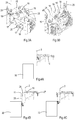
- Figure 1 shows a template 1 comprising a plurality of guide tubes 2 fixed in a geometric pattern by means of beams or trusses 3.
- the pattern of the centrelines of the guide tubes corresponds to that of foundation piles for e.g. a jacket for a wind turbine to be installed.
- the guide tubes are arranged in a square.
- the template is provided with at least a pressure sensor (not shown) to establish depth and with an inclination sensor.
- the guide tubes 2 have a circular cross-section, an inner diameter larger than 1 meter, e.g. 2 meters, and are provided with internal guide elements 5 to center and support the piles during insertion in the guide tubes.
- Each of the guide tubes 2 comprises at its upper halve, e.g. near its top end, a measuring device 9, shown in detail in Figures 2 , 3A, and 3B , to measure the height of a pile in the tube, i.e. after it has been driven into the underwater ground formation.
- the measuring devices are positioned outside the guide tubes, behind a door or panel 11 in the wall of each of the tubes.
- the measuring device 9 comprises a mounting frame 12 with which it is mounted in the template and an arm 10 that is movable, i.c. slidable, on or in the frame by means of e.g. an hydraulic cylinder 13, between a retracted position ( Figure 4A ) and an extended position ( Figures 4B and 4C ).
- the measuring device further comprises two proximity sensors 15, in this example SICK IMA30-40NE1ZC0K, located next to each other in a carrying frame 16, with one of the sensors positioned slightly higher, e.g. 1 to 50 millimeters higher, than the other.
- the frame further carries two pressure sensors 17, positioned a calibrated distance below the proximity sensors 15, a camera 18 at exactly the same height position as the proximity sensors 15, and a lamp integrated in the camera.
- a reticle 19 is positioned in front of the camera to facilitate optically measuring the height position of a rim or marker of or on a foundation element inside the guide tube 2.
- Guide wheels 20 are mounted on either side and in the middle, at the bottom side, of the frame 16.
- the frame is suspended from the arm via a pair of cables 25 that are guided over pulleys 26 at the front end of the arm, i.e. the end closest to the guide tube, and towards winches 27 at the rear end of the arm.
- the cables are wound on the winches.
- the cables contain power wires to feed electricity to the sensor, camera, lamp, and pressure sensor and data wires to transmit data from the sensors and camera.
- the arm 10 is extended until the frame 16 carrying the proximity sensors 15 is above the space between the pile and the inner wall of the guide tube.
- the frame and sensors are lowered by paying out the cables 25 with the winches 27, alongside the outer wall the pile.
- the arm 10 is extended further until the wheels 20 on the frame 16 rest under some bias against the outer wall of the pile.
- the frame and sensors are pulled up. When the upper sensor of the two proximity sensors reaches the upper rim of the pile, the sensor will generate a signal.
- the output voltage or current of the proximity sensor decreases and a decrease of 50% is considered to correspond to a position of the upper sensor at the rim.
- the pressure measured with the pressure sensor 17 on the frame 16 is compared to a reference, in this example the pressure measured by the pressure sensor on the template, to establish the height of the upper rim of the pile.
- the other piles are driven into the seabed to the same stickup height as the first. After the heights of these piles have been measured and compared to the stickup height of the first pile, it is decided whether further pile driving, e.g. to achieve an equal height for all piles, is necessary.
- the measuring system according to the present invention enables measuring a relatively large range, e.g. between 1 and 10 meters, of stickup heights with relatively little interference with the guide member or members.
- the arm can be extended beneath the guide member and the sensor lifted, e.g. by means of a telescoping column, along the outer wall of a foundation element present inside a guide member.
- the measuring device comprises three or four proximity sensors, e.g. all at different heights.
Landscapes
- Engineering & Computer Science (AREA)
- Life Sciences & Earth Sciences (AREA)
- General Life Sciences & Earth Sciences (AREA)
- Mining & Mineral Resources (AREA)
- Paleontology (AREA)
- Civil Engineering (AREA)
- General Engineering & Computer Science (AREA)
- Structural Engineering (AREA)
- Placing Or Removing Of Piles Or Sheet Piles, Or Accessories Thereof (AREA)
Priority Applications (1)
| Application Number | Priority Date | Filing Date | Title |
|---|---|---|---|
| EP17157205.0A EP3363952A1 (fr) | 2017-02-21 | 2017-02-21 | Pieu de fondation |
Applications Claiming Priority (1)
| Application Number | Priority Date | Filing Date | Title |
|---|---|---|---|
| EP17157205.0A EP3363952A1 (fr) | 2017-02-21 | 2017-02-21 | Pieu de fondation |
Publications (1)
| Publication Number | Publication Date |
|---|---|
| EP3363952A1 true EP3363952A1 (fr) | 2018-08-22 |
Family
ID=58108480
Family Applications (1)
| Application Number | Title | Priority Date | Filing Date |
|---|---|---|---|
| EP17157205.0A Withdrawn EP3363952A1 (fr) | 2017-02-21 | 2017-02-21 | Pieu de fondation |
Country Status (1)
| Country | Link |
|---|---|
| EP (1) | EP3363952A1 (fr) |
Citations (3)
| Publication number | Priority date | Publication date | Assignee | Title |
|---|---|---|---|---|
| US5244312A (en) | 1991-12-29 | 1993-09-14 | Conoco Inc. | Pile supported drilling template |
| EP2492401A1 (fr) | 2011-02-22 | 2012-08-29 | GeoSea NV | Appareil de manufacture d'une fondation pour une masse localisée en hauteur, méthode associée et ensemble formé par l'appareil et une plateforme surélevée |
| EP2851472A1 (fr) * | 2013-08-26 | 2015-03-25 | GeoSea NV | Dispositif pour guidance d'un pieu |
-
2017
- 2017-02-21 EP EP17157205.0A patent/EP3363952A1/fr not_active Withdrawn
Patent Citations (3)
| Publication number | Priority date | Publication date | Assignee | Title |
|---|---|---|---|---|
| US5244312A (en) | 1991-12-29 | 1993-09-14 | Conoco Inc. | Pile supported drilling template |
| EP2492401A1 (fr) | 2011-02-22 | 2012-08-29 | GeoSea NV | Appareil de manufacture d'une fondation pour une masse localisée en hauteur, méthode associée et ensemble formé par l'appareil et une plateforme surélevée |
| EP2851472A1 (fr) * | 2013-08-26 | 2015-03-25 | GeoSea NV | Dispositif pour guidance d'un pieu |
Similar Documents
| Publication | Publication Date | Title |
|---|---|---|
| US8834071B2 (en) | Device for manufacturing a foundation for a mass located at height, associated method and assembly of the device and a jack-up platform | |
| CN102607488B (zh) | 一种监测滑坡滑动面位移变形的装置及方法 | |
| KR101459063B1 (ko) | 트렌치 벽 요소를 생성하기 위한 방법 및 장치 | |
| US11340379B2 (en) | Borehole inspecting and testing device and method of using the same | |
| EP3859086B1 (fr) | Boroscope pour inspection de forage | |
| CN212620628U (zh) | 一种建筑工程监理用桩孔孔径检测装置 | |
| CN108132263A (zh) | 地下连续墙内部缺陷跨孔雷达检测装置和方法 | |
| CN110736422A (zh) | 一种预制磁场布设系统及变形状态响应方法 | |
| EP3363952A1 (fr) | Pieu de fondation | |
| CN116839554A (zh) | 一种土地测绘用河沟深度测量装置 | |
| JP3271751B2 (ja) | 沈下計測装置 | |
| KR20100131072A (ko) | 지표면 침하량 측정장치 | |
| US11649716B2 (en) | Borescope for drilled shaft inspection | |
| CN210321716U (zh) | 一种倾斜观测装置 | |
| JP2014178304A (ja) | 管状構造物の計測装置及び評価方法 | |
| KR101527203B1 (ko) | 관입 위치 측정 기반의 관입 시험 장치 | |
| CN209083279U (zh) | 一种用于检验钻孔数据的验孔器 | |
| CN217840121U (zh) | 一种检验地下障碍物下土方开挖完成装置 | |
| JP2021080794A (ja) | 掘削孔測定器 | |
| CN215639587U (zh) | 一种深基坑监测装置 | |
| GB2569661A (en) | Apparatus and method for pile head leveling | |
| CN219656893U (zh) | 土建墙体垂直度校准装置 | |
| CN218090996U (zh) | 一种低误差桩基声波透射检测装置 | |
| CN218496147U (zh) | 一种地下水位、井台高度一体化测量装置 | |
| CN115855029B (zh) | 基于沉管运安一体船吊索的管节沉放粗定位系统及方法 |
Legal Events
| Date | Code | Title | Description |
|---|---|---|---|
| PUAI | Public reference made under article 153(3) epc to a published international application that has entered the european phase |
Free format text: ORIGINAL CODE: 0009012 |
|
| STAA | Information on the status of an ep patent application or granted ep patent |
Free format text: STATUS: THE APPLICATION HAS BEEN PUBLISHED |
|
| AK | Designated contracting states |
Kind code of ref document: A1 Designated state(s): AL AT BE BG CH CY CZ DE DK EE ES FI FR GB GR HR HU IE IS IT LI LT LU LV MC MK MT NL NO PL PT RO RS SE SI SK SM TR |
|
| AX | Request for extension of the european patent |
Extension state: BA ME |
|
| STAA | Information on the status of an ep patent application or granted ep patent |
Free format text: STATUS: REQUEST FOR EXAMINATION WAS MADE |
|
| 17P | Request for examination filed |
Effective date: 20190222 |
|
| RBV | Designated contracting states (corrected) |
Designated state(s): AL AT BE BG CH CY CZ DE DK EE ES FI FR GB GR HR HU IE IS IT LI LT LU LV MC MK MT NL NO PL PT RO RS SE SI SK SM TR |
|
| STAA | Information on the status of an ep patent application or granted ep patent |
Free format text: STATUS: EXAMINATION IS IN PROGRESS |
|
| STAA | Information on the status of an ep patent application or granted ep patent |
Free format text: STATUS: REQUEST FOR EXAMINATION WAS MADE |
|
| STAA | Information on the status of an ep patent application or granted ep patent |
Free format text: STATUS: EXAMINATION IS IN PROGRESS |
|
| GRAP | Despatch of communication of intention to grant a patent |
Free format text: ORIGINAL CODE: EPIDOSNIGR1 |
|
| STAA | Information on the status of an ep patent application or granted ep patent |
Free format text: STATUS: GRANT OF PATENT IS INTENDED |
|
| 17Q | First examination report despatched |
Effective date: 20200422 |
|
| INTG | Intention to grant announced |
Effective date: 20200515 |
|
| STAA | Information on the status of an ep patent application or granted ep patent |
Free format text: STATUS: THE APPLICATION IS DEEMED TO BE WITHDRAWN |
|
| 18D | Application deemed to be withdrawn |
Effective date: 20200926 |