EP3363736B1 - Landing gear drive system flexible interface - Google Patents
Landing gear drive system flexible interface Download PDFInfo
- Publication number
- EP3363736B1 EP3363736B1 EP18157783.4A EP18157783A EP3363736B1 EP 3363736 B1 EP3363736 B1 EP 3363736B1 EP 18157783 A EP18157783 A EP 18157783A EP 3363736 B1 EP3363736 B1 EP 3363736B1
- Authority
- EP
- European Patent Office
- Prior art keywords
- pinion gear
- drive
- gear
- balls
- grooves
- Prior art date
- Legal status (The legal status is an assumption and is not a legal conclusion. Google has not performed a legal analysis and makes no representation as to the accuracy of the status listed.)
- Active
Links
Images


Classifications
-
- B—PERFORMING OPERATIONS; TRANSPORTING
- B64—AIRCRAFT; AVIATION; COSMONAUTICS
- B64C—AEROPLANES; HELICOPTERS
- B64C25/00—Alighting gear
- B64C25/32—Alighting gear characterised by elements which contact the ground or similar surface
- B64C25/405—Powered wheels, e.g. for taxing
-
- F—MECHANICAL ENGINEERING; LIGHTING; HEATING; WEAPONS; BLASTING
- F16—ENGINEERING ELEMENTS AND UNITS; GENERAL MEASURES FOR PRODUCING AND MAINTAINING EFFECTIVE FUNCTIONING OF MACHINES OR INSTALLATIONS; THERMAL INSULATION IN GENERAL
- F16D—COUPLINGS FOR TRANSMITTING ROTATION; CLUTCHES; BRAKES
- F16D3/00—Yielding couplings, i.e. with means permitting movement between the connected parts during the drive
- F16D3/02—Yielding couplings, i.e. with means permitting movement between the connected parts during the drive adapted to specific functions
- F16D3/06—Yielding couplings, i.e. with means permitting movement between the connected parts during the drive adapted to specific functions specially adapted to allow axial displacement
- F16D3/065—Yielding couplings, i.e. with means permitting movement between the connected parts during the drive adapted to specific functions specially adapted to allow axial displacement by means of rolling elements
-
- F—MECHANICAL ENGINEERING; LIGHTING; HEATING; WEAPONS; BLASTING
- F16—ENGINEERING ELEMENTS AND UNITS; GENERAL MEASURES FOR PRODUCING AND MAINTAINING EFFECTIVE FUNCTIONING OF MACHINES OR INSTALLATIONS; THERMAL INSULATION IN GENERAL
- F16D—COUPLINGS FOR TRANSMITTING ROTATION; CLUTCHES; BRAKES
- F16D3/00—Yielding couplings, i.e. with means permitting movement between the connected parts during the drive
- F16D3/16—Universal joints in which flexibility is produced by means of pivots or sliding or rolling connecting parts
- F16D3/18—Universal joints in which flexibility is produced by means of pivots or sliding or rolling connecting parts the coupling parts (1) having slidably-interengaging teeth
- F16D3/185—Universal joints in which flexibility is produced by means of pivots or sliding or rolling connecting parts the coupling parts (1) having slidably-interengaging teeth radial teeth connecting concentric inner and outer coupling parts
-
- F—MECHANICAL ENGINEERING; LIGHTING; HEATING; WEAPONS; BLASTING
- F16—ENGINEERING ELEMENTS AND UNITS; GENERAL MEASURES FOR PRODUCING AND MAINTAINING EFFECTIVE FUNCTIONING OF MACHINES OR INSTALLATIONS; THERMAL INSULATION IN GENERAL
- F16D—COUPLINGS FOR TRANSMITTING ROTATION; CLUTCHES; BRAKES
- F16D3/00—Yielding couplings, i.e. with means permitting movement between the connected parts during the drive
- F16D3/16—Universal joints in which flexibility is produced by means of pivots or sliding or rolling connecting parts
- F16D3/20—Universal joints in which flexibility is produced by means of pivots or sliding or rolling connecting parts one coupling part entering a sleeve of the other coupling part and connected thereto by sliding or rolling members
- F16D3/22—Universal joints in which flexibility is produced by means of pivots or sliding or rolling connecting parts one coupling part entering a sleeve of the other coupling part and connected thereto by sliding or rolling members the rolling members being balls, rollers, or the like, guided in grooves or sockets in both coupling parts
- F16D3/223—Universal joints in which flexibility is produced by means of pivots or sliding or rolling connecting parts one coupling part entering a sleeve of the other coupling part and connected thereto by sliding or rolling members the rolling members being balls, rollers, or the like, guided in grooves or sockets in both coupling parts the rolling members being guided in grooves in both coupling parts
-
- F—MECHANICAL ENGINEERING; LIGHTING; HEATING; WEAPONS; BLASTING
- F16—ENGINEERING ELEMENTS AND UNITS; GENERAL MEASURES FOR PRODUCING AND MAINTAINING EFFECTIVE FUNCTIONING OF MACHINES OR INSTALLATIONS; THERMAL INSULATION IN GENERAL
- F16H—GEARING
- F16H19/00—Gearings comprising essentially only toothed gears or friction members and not capable of conveying indefinitely-continuing rotary motion
- F16H19/02—Gearings comprising essentially only toothed gears or friction members and not capable of conveying indefinitely-continuing rotary motion for interconverting rotary or oscillating motion and reciprocating motion
- F16H19/04—Gearings comprising essentially only toothed gears or friction members and not capable of conveying indefinitely-continuing rotary motion for interconverting rotary or oscillating motion and reciprocating motion comprising a rack
-
- Y—GENERAL TAGGING OF NEW TECHNOLOGICAL DEVELOPMENTS; GENERAL TAGGING OF CROSS-SECTIONAL TECHNOLOGIES SPANNING OVER SEVERAL SECTIONS OF THE IPC; TECHNICAL SUBJECTS COVERED BY FORMER USPC CROSS-REFERENCE ART COLLECTIONS [XRACs] AND DIGESTS
- Y02—TECHNOLOGIES OR APPLICATIONS FOR MITIGATION OR ADAPTATION AGAINST CLIMATE CHANGE
- Y02T—CLIMATE CHANGE MITIGATION TECHNOLOGIES RELATED TO TRANSPORTATION
- Y02T50/00—Aeronautics or air transport
- Y02T50/80—Energy efficient operational measures, e.g. ground operations or mission management
Definitions
- the present invention relates to a flexible interface between an aircraft landing gear wheel and a drive system for rotating that wheel for the purposes of ground taxiing.
- Aircraft are required to ground taxi between locations on airfields.
- An example is taxiing between a runway and the location (e.g. terminal gate) at which the aircraft's passengers are to board or disembark.
- Such taxiing is achieved by using the thrust from the aircraft's engines to propel the aircraft forwards so that the landing gear wheels are caused to rotate.
- ground taxi speeds are necessarily relatively low, the engines must be run at a very low power. This means that there is a relatively high fuel consumption as a result of the poor propulsion efficiency at this low power. This leads to an increased level of both atmospheric and noise pollution locally around airports.
- even when the engines are run at low power it is generally necessary to apply the wheel brakes to limit ground taxi speeds, leading to a high degree of brake wear.
- WO2011/023505 Two prior art arrangements which are not restricted to nose landing gears are described in WO2011/023505 and WO2011/073590 .
- the disclosed system uses an actuator to move a driven toothed pinion gear in and out of driving engagement with a toothed ring gear on the wheel.
- the invention according to independent claim 1 provides a drive system for an aircraft landing gear, the drive system comprising: a pinion gear; a drive shaft arranged to rotate the pinion gear about a drive axis; a driven gear arranged to mesh with the pinion gear to be rotatable by the pinion gear, the driven gear being connectable to a wheel of the landing gear to be capable of rotating the wheel about a wheel axis; a first spline joint between the drive shaft and the pinion gear arranged to permit tilting of the pinion gear relative to the drive axis; and a second spline joint between the drive shaft and the pinion gear arranged to permit translation of the pinion gear along the drive axis relative to the drive shaft.
- a pair of springs provide opposed forces which bias the pinion gear towards a central position along the drive axis.
- the springs may be coil springs, diaphragm springs, or petal springs for example.
- the flexible interface comprises a ball or roller joint with a plurality of pairs of face-to-face grooves distributed around the drive axis, and a plurality of balls or rollers, each pair of face-to-face grooves containing one or more of the balls or rollers, wherein the balls or rollers are arranged to transmit torque between the drive shaft and the pinion gear and to permit tilting of the pinion gear relative to the drive axis.
- the flexible interface comprises a ball joint with a plurality of pairs of face-to-face grooves distributed around the drive axis; and a plurality of balls,
- Each pair of face-to-face grooves contains one or more of the balls, and the balls are arranged to transmit torque between the drive shaft and the pinion gear and to permit tilting of the pinion gear relative to the drive axis.
- Each pair of face-to-face grooves may contain a single ball only, but more preferably each pair contains three or more of the balls arranged in a line.
- each groove is preferably curved along its length so that the radial distance of the balls from the drive axis varies along the line of balls reaching a maximum at or near a centre of the line and decreasing either side of the maximum.
- Each pair of grooves may have a constant width, but more typically one groove in each pair of grooves has a crowned pair of sides, so its width tapers along its length reaching a minimum at or near a centre of the groove and increasing either side of the minimum.
- the flexible interface comprises a roller joint with a plurality of pairs of face-to-face grooves distributed around the drive axis; and a plurality of rollers, wherein each pair of face-to-face grooves contains one or more of the rollers, each roller has a roller axis around which the roller can rotate, and each roller is crowned along its roller axis to permit tilting of the pinion gear relative to the drive axis.
- each pair of grooves contains only a single roller. The grooves may be crowned or straight.
- each wheel axle 220 is deflected relative to the landing gear leg 230 as a result of the vertical loads due to the weight of the aircraft ( Figure 1A ; 220A indicates the wheel axle before deflection, and 220B indicates it after deflection) and the horizontal loads applied during braking ( Figure 1B ; 220A indicates the wheel axle before deflection, and 220B indicates it after deflection).
- Figure 1A indicates the wheel axle before deflection
- 220B indicates it after deflection
- the shape of each wheel rim 210 is deformed (to a lozenge, or oval, shape) due to tyre loads ( Figure 1C ; 210A indicates the wheel rim before deflection, and 210B indicates it after deflection).
- Each deformation mode typically provides deformation within the range of +/-10mm at the extremities of the wheel.
- the vertical height of the wheel may be reduced by 10mm as a result of wheel distortion by tyre loads, and the wheel may tilt through about 2-3 degrees as a result of axle bending caused by vertical aircraft loads, resulting in a displacement of about 10mm at the periphery of the wheel rim.
- An exemplary drive system 100 for autonomous taxiing of an aircraft as shown in Figures 2 to 4 is arranged to drive a wheel 200 of the landing gear.
- the drive system 100 comprises a pinion gear 110 mounted on a drive shaft 120 via a flexible interface comprising a coupling member 300, the drive shaft 120 being driven by an appropriately geared motor (not shown) to rotate about a drive axis.
- the motor may be arranged to drive only one wheel, or two or more wheels via a differential or similar.
- one, some, or all of the wheels of the landing gear may be actively driven by the drive system, and there may be multiple drive systems per landing gear.
- the pinion gear 110 is meshed with a driven gear 130 which is in the form of an annular rim gear attached to a wheel rim 210 of the wheel 200 via a flexible interface comprising three driven gear coupling members 400 distributed evenly around the wheel rim 210.
- the driven gear has a larger diameter than the drive pinion. This arrangement provides for a torque-magnifying gear ratio and an efficient use of space.
- the wheel rim deformation ( Figure 1C ) due to tyre loads can result in a translational displacement of the driven gear 130 with respect to the pinion gear 110, i.e. the rotational axes of these gears are displaced with respect to one another.
- Such wheel rim deformation may also cause undesirable distortion of the driven gear 130.
- a rigid connection between the driven gear 130 and the wheel 200 may cause further distortion within the wheel rim 210.
- the flexible interface 300, 400 serves to isolate the drive system 100 from these deformations.
- the driven gear coupling members 400 of the flexible interface each comprise a joint member 410 having a shaft portion 412 which is received within a bushing 420 mounted through a web of the driven gear 130, the shaft portion 412 being capable of both limited translational and rotational movement within the bushing 420 to provide a kinematic cylindrical joint.
- the joint member 410 also has a ball portion 414 separated from the shaft portion 412 by a connecting portion 416, the ball portion 414 being received within a socket member 430.
- the socket member 430 is rigidly connected to the wheel rim 210 and has a socket chamber 432 within which the ball portion 414 is located and a slot opening 416 through which the connecting portion 416 extends and which provides an opening to the socket chamber 432.
- the socket chamber 432 is generally elongate to permit movement of the ball portion 414 of the joint member 410 along a linear path delimited by the extent of the slot opening 416.
- the ball portion 414 is also able to rotate within the chamber 432. In this way, the ball portion 414 and socket member 430 provide a kinematic ball and socket joint.
- Each socket member 430 includes a spring 440 which is arranged to urge the ball portion 414 towards the wheel axis. In this way, the three springs 440 serve to centre the driven gear 130 with respect to the wheel rim 210.
- Each socket member 430 also includes a catch finger 450 which is rigidly attached to the socket member 430 and extends therefrom through an oversized through hole 455 through the web of the driven gear 130.
- the through hole 455 is sized to ensure that there is no contact between the catch finger 450 and the driven gear 130 during normal operation of the drive system 100, but if the joint member 410 of the driven gear coupling member 400 were to break, or the coupling member otherwise fail, the catch 450 would retain the driven gear 130 and maintain a connection with the wheel 200.
- Figures 6, 7, 8A and 8B show possible configurations of the socket member 430, the appropriate configuration being selected according to the specific wheel deformation modes to be accommodated.
- the chamber 432 is arranged to provide a straight linear translation of the ball portion 414 in a substantially radial direction of the wheel axis about which the wheel 200 rotates.
- the chamber 432 is arranged to provide a straight linear translation of the ball portion 414 in a direction which is at an angle to the radial direction of the wheel axis.
- Figures 8A and 8B the chamber is arranged to provide a curved linear translation of the ball portion 414 (the line in Figure 8A indicating the line of translation) which is at an angle to the radial direction of the wheel axis.
- the coupling member 300 shown in Figures 9A and 9C provides a flexible interface comprising a crowned spline joint between the drive shaft 120 and the pinion gear 110 to permit tilting of the pinion gear with respect to the rotational axis 121 of the drive shaft.
- the coupling member 300 includes a plurality of male external splines 310 (and associated female external grooves) which are received within a corresponding plurality of female internal grooves 320 (and associated male internal splines) formed in the pinion gear 110.
- Each spline 310 has an opposed pair of sides, an opposed pair of ends, and a top which provides the outer diameter of the spline and runs between the ends and sides of the spline.
- the spline has a length (labelled “L” in Figure 9C ) between its two ends and a thickness (labelled “t” in Figure 9C ) between its side faces.
- the splines 310 are crowned to permit tilting of the pinion gear 110 relative to the drive axis 121 of the drive shaft 120.
- the splines 310 are crowned in two senses. Firstly, the sides of each spline 310 are crowned (i.e. domed or rounded) along the length of the spline so that the thickness "t" of the spline is at a maximum at or near its centre and gradually decreases to either side reaching a minimum at its opposed ends.
- the varying thickness of one of the splines can be seen clearly in Figure 9C , with the maximum thickness at the centre of spline being shown.
- each spline 310 is also crowned (i.e domed or rounded) along the length of the spline so that the outer diameter of the spline (labelled "OD" in Figure 9A ) from the top of the spline to the drive axis 121 is at a maximum at its centre and gradually decreases to either side reaching a minimum at its opposed ends.
- the coupling member 300 as a whole has a barrel shape when viewed from the side as in Figure 9A .
- the female internal grooves 320 (and associated male internal splines) formed in the pinion gear 110 as shown in Figure 9B are not crowned - in other words they have a thickness and outer diameter which do not vary along the length of the spline.
- the curved spline shape described above enables the pinion gear 110 to tilt with respect to the drive shaft 120.
- the joint may include ball bearings (not shown) within the grooves 320 to facilitate this movement.
- the coupling member 300 may be slidably mounted on the drive shaft 120 to permit relative translation between the pinion gear 110 and the drive shaft 120. This relative translation is desirable to accommodate build tolerances, and also enables the pinion to translate to accommodate lateral bending of the wheel rim which can occur during operation of the aircraft.
- the driven gear coupling members 400 may not be necessary for the driven gear coupling members 400 to include the shaft portion 412 and the bushing 420, and instead the connecting portion 416 may be rigidly connected to the driven gear 130.
- ball portion 414 and socket chamber 432 may be replaced by a shaft portion and bushing (not shown) to provide a kinematic cylindrical joint.
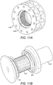
- Figures 10-12 show an embodiment of the invention in which the coupling member is slidably mounted on the drive shaft to permit relative translation between the pinion gear and the drive shaft.
- Many of the components in Figures 10-12 have equivalents in Figures 1-9 , and the same reference number will be used (appended by the letter "a") for such components.
- the drive shaft 120a shown in Figure 11b has external splines 500 (and associated grooves) between a pair of helical springs 501, 502.
- the coupling member 300a shown in Figure 11c has internal splines 510 which mate with the external splines 500 of the drive shaft.
- the splines 500, 510 are axially straight rather than being crowned.
- the coupling member 300a On either side of the internal splines 500 the coupling member 300a carries collars 511, 512 of low friction material (shown in Figure 10 ) which provide a low friction sliding bearing enabling the coupling member 300a to slide axially along the drive shaft 120a.
- the springs 501, 502 provide opposed forces which bias the coupling member 300a (and the pinion gear 110a) towards a central position shown in Figure 10 .
- Each spring 501, 502 has only 2-3 turns within the space available which may lead to biasing the coupling member 300a at a tilt. To combat this, other spring types may optionally be used, for example a diaphragm spring or petal spring.
- the coupling member 300a also has external splines 310a ( Figure 11C ) which are crowned as in the relevant previous example.
- the external splines 310a (and associated female external grooves) cooperate with a corresponding plurality of female internal grooves 320a (and associated male internal splines) formed in the pinion gear 110a as shown in Figure 11A .
- the male internal splines may be straight or they may be crowned like the external splines 310a.
- the coupling member 300a has convex spherical surfaces 520,521 on either side of the crowned external splines 310a.
- the pinion gear 110a has concave spherical surfaces 530,531 on either side of the internal splines which bear against the convex spherical surfaces 520,521 of the coupling member 310a as shown in Figure 10 .
- This spherical bearing enables the pinion gear 110a to tilt with respect to the drive shaft 120a by +/- 2.5deg as shown in Figures 12a and 12b.
- Figure 12a shows the pinion gear 110a rotated clockwise by 2.5deg
- Figure 12b shows the pinion gear 110a rotated anti-clockwise by 2.5deg.
- the drive shaft 120a is coupled to the pinion gear 110a by a compound or double spline joint: i.e. a spline joint with a first crowned spline joint arranged to permit tilting of the pinion gear relative to the drive axis, and a second un-crowned spline joint arranged to permit translation of the pinion gear along the drive axis relative to the drive shaft.
- the coupling member 300a is arranged to transmit torque to the pinion gear 100a via the first spline joint and to receive torque from the drive shaft 120a via the second spline joint.
- the pinion gear is formed in two parts: a first part with the internal grooves 320a and the spherical concave surface 530, and a second part with the spherical concave surface 531.
- the second part can be removed to enable the coupling member 300a to be removed.
- Figures 13 and 14 show an alternative two-part pinion gear which can be used in the compound spline joint of Figures 10-12 .
- Many of the components in Figures 13 and 14 have equivalents in Figures 10-12 , and the same reference number will be used (appended by the letter "b") for such components.
- a pair of coupling parts 602,603 shown in Figure 14 are fitted inside the pinion gear 110b and held in place by a circlip 604.
- the pinion gear 110b is coupled to the two parts 602,603 by a third spline joint which unlike the first and second spline joints in the flexible interface does not permit relative tilting or translation.
- the pinion gear has internal splines 600 and grooves which couple with external splines and grooves in the parts 602,603 to form this third spline joint.
- the two parts 602, 603 can be separated to enable the coupling member 300a to be fitted and removed.
- Figures 15-20 show a compound ball spline joint according to a further embodiment of the invention for use in the drive system of Figures 1-8 .
- Many of the components in Figures 15-18 have equivalents in Figures 1-9 , and the same reference number will be used (appended by the letter "c") for such components.
- a barrel-shaped coupling member 300c provides a flexible interface between a drive shaft 120c and the pinion gear.
- Item 704 in Figure 18 could either be the pinion gear, or a coupling member similar to the parts 602, 603 shown in Figure 14 which can transmit torque from the coupling member 300c to the pinion gear via a third spline joint.
- the flexible interface comprises a first spline joint between the drive shaft 120c and the pinion gear arranged to permit tilting of the pinion gear relative to the drive axis; and a second spline joint between the drive shaft and the pinion gear arranged to permit translation of the pinion gear along the drive axis relative to the drive shaft.
- the first spline joint is provided by a plurality of balls 702 received within crowned external grooves 700 distributed around the drive axis.
- the grooves 700 are crowned in the sense that the base of the groove is domed or rounded along its length so that the outer diameter of the base of the groove (that is, its distance to the drive axis) is at a maximum at its centre and gradually decreases to either side, reaching a minimum at its opposed ends. This is shown most clearly in Figure 18b .
- Each line of five balls 702 forms a respective ball spline.
- the balls 702 are received in corresponding internal grooves 705 (shown in Figures 19 and 20 ) in the interior of the pinion gear/coupling member 704.
- Figure 19 Three pairs of face-to-face grooves 700,705 are shown in cross-section in Figure 19 , which is a cross-section through the centre of these three pairs of grooves and a central one of three associated lines of balls 702. At this point the grooves 700, 705 have the same width.
- Figure 20 is a view of one of the internal grooves 705 viewed from the direction of the drive axis. The sides of the groove 705 are crowned along their length so the width W of the groove 705 tapers along its length with a minimum at or near its centre (as in Figure 19 ) and increasing either side of the minimum.
- the grooves 700, 705 are curved along their length so that the radial distance of the balls 702 from the drive axis varies along the line of balls, reaching a maximum at or near a centre of the line (i.e. at the central ball as shown in Figure 19 ) and decreasing either side of the maximum.
- the crowned shape of the grooves means that the outer diameter of each ball spline is also crowned, enabling the pinion gear/coupling member 704 to tilt with respect to the drive shaft 120c.
- Figures 18a and 18b show the pinion gear/coupling member 704 slightly tilted clockwise to illustrate this tilting motion.
- the drive shaft 120c shown in Figure 17 has straight (un-crowned) external grooves 703 and the coupling member 300c has corresponding straight (un-crowned) internal grooves 701 shown in Figure 16 .
- the second spline joint is provided by ball bearings 720c seated in the straight grooves 701,703 which provide a set of ball splines between the drive shaft 120c and the coupling member 300c.
- the ball bearings 720c transmit torque from the drive shaft 120c to the coupling member 300c, but can also roll along the grooves 703 to enable the coupling member 300c to slide axially along the drive shaft 120c. Only one ball bearing 720c is shown in Figure 17 to make the grooves 703 visible. However it will be appreciated that each groove will be filled with a line of such ball bearings 720c as shown in Figure 18b , each line of ball bearings 720c providing a respective spline of the second spline joint.
- the coupling member 300c is arranged to transmit torque to the pinion gear via the first spline joint (either directly, or via a second coupling member 602, 603 and a third spline joint) and to receive torque from the drive shaft via the second spline joint.
- Figures 21-23 show the constituent parts of a compound spline joint according to a further embodiment of the invention for use in the drive system of Figures 1-8 . Many of the components in Figures 21-23 have equivalents in Figures 15-20 , and the same reference number will be used (appended by the letter "d") for such components.
- a coupling member 300d provides a flexible interface between a drive shaft 120d and a pinion gear.
- Item 704d in Figure 22 is either the pinion gear, or a coupling member similar to the parts 602, 603 shown in Figure 14 which can transmit torque to the pinion gear via a third spline joint.
- a first spline joint is provided by a plurality of rollers 702d received within internal grooves 705d (which may be crowned or straight) in the part 704d.
- the coupling member 300d has external grooves 700d which are typically crowned in the same manner as the grooves 700 in the previous embodiment (although they may be straight).
- Each roller 702d forms a respective crowned roller spline which is received in a respective pair of face-to-face grooves 700d, 705d.
- Each roller 702d is crowned or barrel shaped.
- each roller has a roller axis around which it can rotate, and each roller is crowned or domed along its roller axis so its outer diameter (that is its side-to-side diameter transverse to the roller axis) is at a maximum at its centre and gradually decreases to either side, reaching a minimum at its opposed ends.
- This crowned shape of the rollers 702d enables the pinion gear/coupling member 704d to tilt with respect to the drive shaft 120d.
- the drive shaft 120d has straight external grooves (not shown) and the coupling member 300d has corresponding straight internal grooves 701d shown in Figure 21 .
- a second spline joint is provided by ball bearings (one indicated at 720d) seated in the grooves 701d to provide a set of ball splines between the drive shaft 120d and the coupling member 300d.
- the ball bearings 720d transmit torque from the drive shaft 120d to the coupling member 300d, but can also roll along the grooves in the drive shaft to enable the coupling member 300d to slide axially along the drive shaft 120d.
- a ball bearing 720d is only shown in one of grooves 701d in the drawing to make the other grooves visible.
- the coupling member 300d is arranged to transmit torque to the pinion gear via the first spline joint (either directly, or via a second coupling member 602, 603 and a third spline joint) and to receive torque from the drive shaft via the second spline joint.
- Figure 24 shows an alternative coupling member 300e which can be substituted for the coupling member 300a shown in Figure 11c so that it transmits torque to the pinion gear via the first spline joint and receives torque from the drive shaft via the second spline joint.
- the tops of the external splines 310e are crowned in a similar fashion to the external splines 310a of the coupling member 300a of Figure 11c .
- the sides of each spline 310e are concave so that the thickness of the spline is at a minimum at or near its centre and gradually increases to either side reaching a minimum at its opposed ends.
- the internal teeth (not shown) of the pinion gear which are received in the grooves between the external splines 310e have convex crowned sides like the splines 310a in the previous embodiment.
- Figure 25 shows a further alternative coupling member 300f which can be substituted for the coupling member 300a shown in Figure 11c so that it transmits torque to the pinion gear via the first spline joint and receives torque from the drive shaft via the second spline joint.
- the external splines are similar to the external splines 310e in the embodiment of Figure 24 , but the internal splines are replaced by straight grooves 701f like the grooves 701, 701d in previous embodiments.
- the grooves 701e receive lines of ball bearings (one of which is shown at 720e) which transmit torque but permit axial translation. Ball bearings 720e are not shown in the other grooves 701f in the drawing to make these grooves visible.
- the pinion gear and driven gear comprise a roller gear (pin gear) or sprocket, respectively.
- the pinion gear may comprise a sprocket and the driven gear may comprise a roller gear.
- a roller gear comprises a series of rollers formed by two rigid annular rings connected together by a series of rollers arranged in a ring to form a continuous track. The rollers are each rotatable about a pin which extends between the annular rings to form a rigid connection between the annular rings.
- the roller gear is shown as having two adjacent rows of rollers; in other embodiments only a single row of rollers may be necessary.
- a key advantage of achieving the motor-wheel connection via a sprocket and roller gear is that such a mechanism is inherently robust and tolerant of environmental contamination. Thus, it may not be necessary to enclose the drive system within a casing to prevent ingress of debris and other contaminants. In contrast, drive system arrangements employing meshing toothed gears, must be suitably protected from contaminants, the required protective casing adding both weight and expense, and making routine inspection difficult.
- Another advantage of the sprocket-roller arrangement is that it is more tolerant of wheel deformation and misalignment between pinion and driven gear than meshing toothed gear arrangements.
- the roller gear may be replaced by a roller chain (also known as an attachment chain, or attachment roller chain) extending around an outer circumference of a support member and being fixed thereto.
- a roller chain also known as an attachment chain, or attachment roller chain
- the driven gear and pinion gear may comprise toothed gears of the type usually used in drive transmissions.
Description
- The present invention relates to a flexible interface between an aircraft landing gear wheel and a drive system for rotating that wheel for the purposes of ground taxiing.
- Aircraft are required to ground taxi between locations on airfields. An example is taxiing between a runway and the location (e.g. terminal gate) at which the aircraft's passengers are to board or disembark. Typically, such taxiing is achieved by using the thrust from the aircraft's engines to propel the aircraft forwards so that the landing gear wheels are caused to rotate. Since ground taxi speeds are necessarily relatively low, the engines must be run at a very low power. This means that there is a relatively high fuel consumption as a result of the poor propulsion efficiency at this low power. This leads to an increased level of both atmospheric and noise pollution locally around airports. Moreover, even when the engines are run at low power it is generally necessary to apply the wheel brakes to limit ground taxi speeds, leading to a high degree of brake wear.
- Reversing of a civil aircraft, e.g. away from a terminal gate, using its main engines is not permitted. When reversing is necessary, or in other situations where ground taxiing via main engine thrust is not practicable, tow trucks are used to manoeuvre aircraft around. This process is laborious and costly.
- There is therefore a need for a drive system to power the wheels of an aircraft landing gear during ground taxi operations.
- Several autonomous ground taxi systems for both driving the wheels while the aircraft is on the ground and spinning them up prior to landing have been proposed in recent years. An example is disclosed in
US2006/0065779 , which proposes a powered nose aircraft wheel system in which a clutch is used to switch between a mode in which the wheel can spin freely and a mode in which the wheel can be driven by an electric motor. The clutch can also operate to enable the motor to pre-spin the wheel prior to landing. - Two prior art arrangements which are not restricted to nose landing gears are described in
WO2011/023505 andWO2011/073590 . The disclosed system uses an actuator to move a driven toothed pinion gear in and out of driving engagement with a toothed ring gear on the wheel. - The invention according to independent claim 1 provides a drive system for an aircraft landing gear, the drive system comprising: a pinion gear; a drive shaft arranged to rotate the pinion gear about a drive axis; a driven gear arranged to mesh with the pinion gear to be rotatable by the pinion gear, the driven gear being connectable to a wheel of the landing gear to be capable of rotating the wheel about a wheel axis; a first spline joint between the drive shaft and the pinion gear arranged to permit tilting of the pinion gear relative to the drive axis; and a second spline joint between the drive shaft and the pinion gear arranged to permit translation of the pinion gear along the drive axis relative to the drive shaft.
- Optionally a pair of springs provide opposed forces which bias the pinion gear towards a central position along the drive axis. The springs may be coil springs, diaphragm springs, or petal springs for example.
- Preferably, the flexible interface comprises a ball or roller joint with a plurality of pairs of face-to-face grooves distributed around the drive axis, and a plurality of balls or rollers, each pair of face-to-face grooves containing one or more of the balls or rollers, wherein the balls or rollers are arranged to transmit torque between the drive shaft and the pinion gear and to permit tilting of the pinion gear relative to the drive axis.
- In one embodiment the flexible interface comprises a ball joint with a plurality of pairs of face-to-face grooves distributed around the drive axis; and a plurality of balls, Each pair of face-to-face grooves contains one or more of the balls, and the balls are arranged to transmit torque between the drive shaft and the pinion gear and to permit tilting of the pinion gear relative to the drive axis. Each pair of face-to-face grooves may contain a single ball only, but more preferably each pair contains three or more of the balls arranged in a line. In this case each groove is preferably curved along its length so that the radial distance of the balls from the drive axis varies along the line of balls reaching a maximum at or near a centre of the line and decreasing either side of the maximum. Each pair of grooves may have a constant width, but more typically one groove in each pair of grooves has a crowned pair of sides, so its width tapers along its length reaching a minimum at or near a centre of the groove and increasing either side of the minimum.
- In another embodiment the flexible interface comprises a roller joint with a plurality of pairs of face-to-face grooves distributed around the drive axis; and a plurality of rollers, wherein each pair of face-to-face grooves contains one or more of the rollers, each roller has a roller axis around which the roller can rotate, and each roller is crowned along its roller axis to permit tilting of the pinion gear relative to the drive axis. Typically each pair of grooves contains only a single roller. The grooves may be crowned or straight.
- Embodiments of the invention will now be described with reference to the accompanying drawings, in which:
-
Figures 1A, 1B and 1C illustrate three modes of deformation experienced by landing gear during use:Figure 1A shows wheel axle deflection due to vertical loads due to the aircraft weight;Figure 1B shows wheel axle deflection due to (horizontal) braking loads; andFigure 1C shows wheel rim deformation due to tyre loads; -
Figure 2 shows an exemplary drive system, with the motor and various features of the landing gear omitted for clarity; -
Figure 3 shows the drive system ofFigure 2 with the pinion gear omitted; -
Figure 4 shows a detail view of the drive system ofFigures 2 and3 ; -
Figures 5A and 5B show a driven gear coupling member of a flexible interface in an exemplary drive system; -
Figures 6, 7, 8A and 8B illustrate variations on the ball/cylindrical joint socket of a driven gear coupling member in an exemplary drive system; -
Figures 9A, 9B and9C show a pinion gear coupling of a flexible interface in an exemplary drive system; -
Figure 10 is a cross-sectional view of a spline joint for a drive system according to an embodiment of the present invention; -
Figure 11a shows a pinion gear of the spline joint ofFigure 10 ; -
Figure 11b shows a drive shaft of the spline joint ofFigure 10 ; -
Figure 11c shows a coupling member of the spline joint ofFigure 10 ; -
Figure 12a is an enlarged view of part of the spline joint ofFigure 10 showing the pinion gear tilted clockwise; -
Figure 12b is an enlarged view of part of the spline joint ofFigure 10 showing the pinion gear tilted anti-clockwise; -
Figures 13 and 14 show an alternative pinion gear; -
Figures 15-20 show a compound spline joint according to a further embodiment of the invention; -
Figures 21-23 show a compound spline joint according to a further embodiment of the invention; -
Figure 24 shows an alternative coupling member; and -
Figure 25 shows a further alternative coupling member. - An aircraft landing gear experiences many different modes of deformation during use. In particular, each wheel axle 220 is deflected relative to the
landing gear leg 230 as a result of the vertical loads due to the weight of the aircraft (Figure 1A ; 220A indicates the wheel axle before deflection, and 220B indicates it after deflection) and the horizontal loads applied during braking (Figure 1B ; 220A indicates the wheel axle before deflection, and 220B indicates it after deflection). In addition, the shape of eachwheel rim 210 is deformed (to a lozenge, or oval, shape) due to tyre loads (Figure 1C ; 210A indicates the wheel rim before deflection, and 210B indicates it after deflection). Each deformation mode typically provides deformation within the range of +/-10mm at the extremities of the wheel. For example, the vertical height of the wheel may be reduced by 10mm as a result of wheel distortion by tyre loads, and the wheel may tilt through about 2-3 degrees as a result of axle bending caused by vertical aircraft loads, resulting in a displacement of about 10mm at the periphery of the wheel rim. - An
exemplary drive system 100 for autonomous taxiing of an aircraft as shown inFigures 2 to 4 is arranged to drive awheel 200 of the landing gear. Thedrive system 100 comprises apinion gear 110 mounted on adrive shaft 120 via a flexible interface comprising acoupling member 300, thedrive shaft 120 being driven by an appropriately geared motor (not shown) to rotate about a drive axis. The motor may be arranged to drive only one wheel, or two or more wheels via a differential or similar. Thus, one, some, or all of the wheels of the landing gear may be actively driven by the drive system, and there may be multiple drive systems per landing gear. Thepinion gear 110 is meshed with a drivengear 130 which is in the form of an annular rim gear attached to awheel rim 210 of thewheel 200 via a flexible interface comprising three drivengear coupling members 400 distributed evenly around thewheel rim 210. The driven gear has a larger diameter than the drive pinion. This arrangement provides for a torque-magnifying gear ratio and an efficient use of space. - The deformation modes discussed above can result in misalignment and/or distortion within the
drive system 100 since thepinion gear 110 is mounted on the leg or axle (not shown) of the landing gear, while the drivengear 130 is mounted on thewheel 200, which is rotatable about the axle. In the absence of theflexible interface Figures 1A and 1B ) can result in a tilt of the drivengear 130 with respect to thepinion gear 110, i.e. the rotational axes of these gears are tilted with respect to one another. Similarly, in the absence of theflexible interface Figure 1C ) due to tyre loads can result in a translational displacement of the drivengear 130 with respect to thepinion gear 110, i.e. the rotational axes of these gears are displaced with respect to one another. Such wheel rim deformation may also cause undesirable distortion of the drivengear 130. Alternatively, a rigid connection between the drivengear 130 and thewheel 200 may cause further distortion within thewheel rim 210. - The
flexible interface drive system 100 from these deformations. - The driven
gear coupling members 400 of the flexible interface each comprise ajoint member 410 having ashaft portion 412 which is received within abushing 420 mounted through a web of the drivengear 130, theshaft portion 412 being capable of both limited translational and rotational movement within thebushing 420 to provide a kinematic cylindrical joint. - The
joint member 410 also has aball portion 414 separated from theshaft portion 412 by a connectingportion 416, theball portion 414 being received within asocket member 430. Thesocket member 430 is rigidly connected to thewheel rim 210 and has asocket chamber 432 within which theball portion 414 is located and aslot opening 416 through which the connectingportion 416 extends and which provides an opening to thesocket chamber 432. Thesocket chamber 432 is generally elongate to permit movement of theball portion 414 of thejoint member 410 along a linear path delimited by the extent of theslot opening 416. Theball portion 414 is also able to rotate within thechamber 432. In this way, theball portion 414 andsocket member 430 provide a kinematic ball and socket joint. - Each
socket member 430 includes aspring 440 which is arranged to urge theball portion 414 towards the wheel axis. In this way, the threesprings 440 serve to centre the drivengear 130 with respect to thewheel rim 210. - Each
socket member 430 also includes acatch finger 450 which is rigidly attached to thesocket member 430 and extends therefrom through an oversized throughhole 455 through the web of the drivengear 130. The throughhole 455 is sized to ensure that there is no contact between thecatch finger 450 and the drivengear 130 during normal operation of thedrive system 100, but if thejoint member 410 of the drivengear coupling member 400 were to break, or the coupling member otherwise fail, thecatch 450 would retain the drivengear 130 and maintain a connection with thewheel 200. -
Figures 6, 7, 8A and 8B show possible configurations of thesocket member 430, the appropriate configuration being selected according to the specific wheel deformation modes to be accommodated. InFigure 6 thechamber 432 is arranged to provide a straight linear translation of theball portion 414 in a substantially radial direction of the wheel axis about which thewheel 200 rotates. InFigure 7 thechamber 432 is arranged to provide a straight linear translation of theball portion 414 in a direction which is at an angle to the radial direction of the wheel axis. InFigures 8A and 8B the chamber is arranged to provide a curved linear translation of the ball portion 414 (the line inFigure 8A indicating the line of translation) which is at an angle to the radial direction of the wheel axis. - The
coupling member 300 shown inFigures 9A and9C provides a flexible interface comprising a crowned spline joint between thedrive shaft 120 and thepinion gear 110 to permit tilting of the pinion gear with respect to therotational axis 121 of the drive shaft. Thecoupling member 300 includes a plurality of male external splines 310 (and associated female external grooves) which are received within a corresponding plurality of female internal grooves 320 (and associated male internal splines) formed in thepinion gear 110. - Each
spline 310 has an opposed pair of sides, an opposed pair of ends, and a top which provides the outer diameter of the spline and runs between the ends and sides of the spline. The spline has a length (labelled "L" inFigure 9C ) between its two ends and a thickness (labelled "t" inFigure 9C ) between its side faces. - The
splines 310 are crowned to permit tilting of thepinion gear 110 relative to thedrive axis 121 of thedrive shaft 120. Thesplines 310 are crowned in two senses. Firstly, the sides of eachspline 310 are crowned (i.e. domed or rounded) along the length of the spline so that the thickness "t" of the spline is at a maximum at or near its centre and gradually decreases to either side reaching a minimum at its opposed ends. The varying thickness of one of the splines can be seen clearly inFigure 9C , with the maximum thickness at the centre of spline being shown. Secondly, the top of eachspline 310 is also crowned (i.e domed or rounded) along the length of the spline so that the outer diameter of the spline (labelled "OD" inFigure 9A ) from the top of the spline to thedrive axis 121 is at a maximum at its centre and gradually decreases to either side reaching a minimum at its opposed ends. As a result thecoupling member 300 as a whole has a barrel shape when viewed from the side as inFigure 9A . - The female internal grooves 320 (and associated male internal splines) formed in the
pinion gear 110 as shown inFigure 9B are not crowned - in other words they have a thickness and outer diameter which do not vary along the length of the spline. - The curved spline shape described above enables the
pinion gear 110 to tilt with respect to thedrive shaft 120. The joint may include ball bearings (not shown) within thegrooves 320 to facilitate this movement. - In other examples the
coupling member 300 may be slidably mounted on thedrive shaft 120 to permit relative translation between thepinion gear 110 and thedrive shaft 120. This relative translation is desirable to accommodate build tolerances, and also enables the pinion to translate to accommodate lateral bending of the wheel rim which can occur during operation of the aircraft. In such embodiments it may not be necessary for the drivengear coupling members 400 to include theshaft portion 412 and thebushing 420, and instead the connectingportion 416 may be rigidly connected to the drivengear 130. - In yet further examples the
ball portion 414 andsocket chamber 432 may be replaced by a shaft portion and bushing (not shown) to provide a kinematic cylindrical joint. -
Figures 10-12 show an embodiment of the invention in which the coupling member is slidably mounted on the drive shaft to permit relative translation between the pinion gear and the drive shaft. Many of the components inFigures 10-12 have equivalents inFigures 1-9 , and the same reference number will be used (appended by the letter "a") for such components. Thedrive shaft 120a shown inFigure 11b has external splines 500 (and associated grooves) between a pair ofhelical springs coupling member 300a shown inFigure 11c hasinternal splines 510 which mate with theexternal splines 500 of the drive shaft. Thesplines internal splines 500 thecoupling member 300a carriescollars Figure 10 ) which provide a low friction sliding bearing enabling thecoupling member 300a to slide axially along thedrive shaft 120a. Thesprings coupling member 300a (and thepinion gear 110a) towards a central position shown inFigure 10 . Eachspring coupling member 300a at a tilt. To combat this, other spring types may optionally be used, for example a diaphragm spring or petal spring. - The
coupling member 300a also hasexternal splines 310a (Figure 11C ) which are crowned as in the relevant previous example. - The
external splines 310a (and associated female external grooves) cooperate with a corresponding plurality of femaleinternal grooves 320a (and associated male internal splines) formed in thepinion gear 110a as shown inFigure 11A . The male internal splines may be straight or they may be crowned like theexternal splines 310a. - The
coupling member 300a has convex spherical surfaces 520,521 on either side of the crownedexternal splines 310a. Thepinion gear 110a has concave spherical surfaces 530,531 on either side of the internal splines which bear against the convex spherical surfaces 520,521 of thecoupling member 310a as shown inFigure 10 . This spherical bearing enables thepinion gear 110a to tilt with respect to thedrive shaft 120a by +/- 2.5deg as shown inFigures 12a and 12b. Figure 12a shows thepinion gear 110a rotated clockwise by 2.5deg andFigure 12b shows thepinion gear 110a rotated anti-clockwise by 2.5deg. - Thus in the embodiment of
Figures 10-12 thedrive shaft 120a is coupled to thepinion gear 110a by a compound or double spline joint: i.e. a spline joint with a first crowned spline joint arranged to permit tilting of the pinion gear relative to the drive axis, and a second un-crowned spline joint arranged to permit translation of the pinion gear along the drive axis relative to the drive shaft. Thecoupling member 300a is arranged to transmit torque to the pinion gear 100a via the first spline joint and to receive torque from thedrive shaft 120a via the second spline joint. - The pinion gear is formed in two parts: a first part with the
internal grooves 320a and the sphericalconcave surface 530, and a second part with the sphericalconcave surface 531. The second part can be removed to enable thecoupling member 300a to be removed. -
Figures 13 and 14 show an alternative two-part pinion gear which can be used in the compound spline joint ofFigures 10-12 . Many of the components inFigures 13 and 14 have equivalents inFigures 10-12 , and the same reference number will be used (appended by the letter "b") for such components. A pair of coupling parts 602,603 shown inFigure 14 are fitted inside thepinion gear 110b and held in place by acirclip 604. Thepinion gear 110b is coupled to the two parts 602,603 by a third spline joint which unlike the first and second spline joints in the flexible interface does not permit relative tilting or translation. The pinion gear hasinternal splines 600 and grooves which couple with external splines and grooves in the parts 602,603 to form this third spline joint. The twoparts coupling member 300a to be fitted and removed. -
Figures 15-20 show a compound ball spline joint according to a further embodiment of the invention for use in the drive system ofFigures 1-8 . Many of the components inFigures 15-18 have equivalents inFigures 1-9 , and the same reference number will be used (appended by the letter "c") for such components. - A barrel-shaped
coupling member 300c provides a flexible interface between adrive shaft 120c and the pinion gear.Item 704 inFigure 18 could either be the pinion gear, or a coupling member similar to theparts Figure 14 which can transmit torque from thecoupling member 300c to the pinion gear via a third spline joint. The flexible interface comprises a first spline joint between thedrive shaft 120c and the pinion gear arranged to permit tilting of the pinion gear relative to the drive axis; and a second spline joint between the drive shaft and the pinion gear arranged to permit translation of the pinion gear along the drive axis relative to the drive shaft. - The first spline joint is provided by a plurality of
balls 702 received within crownedexternal grooves 700 distributed around the drive axis. Thegrooves 700 are crowned in the sense that the base of the groove is domed or rounded along its length so that the outer diameter of the base of the groove (that is, its distance to the drive axis) is at a maximum at its centre and gradually decreases to either side, reaching a minimum at its opposed ends. This is shown most clearly inFigure 18b . Each line of fiveballs 702 forms a respective ball spline. Theballs 702 are received in corresponding internal grooves 705 (shown inFigures 19 and 20 ) in the interior of the pinion gear/coupling member 704. - Three pairs of face-to-face grooves 700,705 are shown in cross-section in
Figure 19 , which is a cross-section through the centre of these three pairs of grooves and a central one of three associated lines ofballs 702. At this point thegrooves Figure 20 is a view of one of theinternal grooves 705 viewed from the direction of the drive axis. The sides of thegroove 705 are crowned along their length so the width W of thegroove 705 tapers along its length with a minimum at or near its centre (as inFigure 19 ) and increasing either side of the minimum. - The
grooves balls 702 from the drive axis varies along the line of balls, reaching a maximum at or near a centre of the line (i.e. at the central ball as shown inFigure 19 ) and decreasing either side of the maximum. - The crowned shape of the grooves means that the outer diameter of each ball spline is also crowned, enabling the pinion gear/
coupling member 704 to tilt with respect to thedrive shaft 120c.Figures 18a and18b show the pinion gear/coupling member 704 slightly tilted clockwise to illustrate this tilting motion. - The
drive shaft 120c shown inFigure 17 has straight (un-crowned)external grooves 703 and thecoupling member 300c has corresponding straight (un-crowned)internal grooves 701 shown inFigure 16 . The second spline joint is provided byball bearings 720c seated in the straight grooves 701,703 which provide a set of ball splines between thedrive shaft 120c and thecoupling member 300c. Theball bearings 720c transmit torque from thedrive shaft 120c to thecoupling member 300c, but can also roll along thegrooves 703 to enable thecoupling member 300c to slide axially along thedrive shaft 120c. Only oneball bearing 720c is shown inFigure 17 to make thegrooves 703 visible. However it will be appreciated that each groove will be filled with a line ofsuch ball bearings 720c as shown inFigure 18b , each line ofball bearings 720c providing a respective spline of the second spline joint. - Thus the
coupling member 300c is arranged to transmit torque to the pinion gear via the first spline joint (either directly, or via asecond coupling member -
Figures 21-23 show the constituent parts of a compound spline joint according to a further embodiment of the invention for use in the drive system ofFigures 1-8 . Many of the components inFigures 21-23 have equivalents inFigures 15-20 , and the same reference number will be used (appended by the letter "d") for such components. - A
coupling member 300d provides a flexible interface between adrive shaft 120d and a pinion gear.Item 704d inFigure 22 is either the pinion gear, or a coupling member similar to theparts Figure 14 which can transmit torque to the pinion gear via a third spline joint. - A first spline joint is provided by a plurality of
rollers 702d received withininternal grooves 705d (which may be crowned or straight) in thepart 704d. Thecoupling member 300d hasexternal grooves 700d which are typically crowned in the same manner as thegrooves 700 in the previous embodiment (although they may be straight). Eachroller 702d forms a respective crowned roller spline which is received in a respective pair of face-to-face grooves roller 702d is crowned or barrel shaped. That is, each roller has a roller axis around which it can rotate, and each roller is crowned or domed along its roller axis so its outer diameter (that is its side-to-side diameter transverse to the roller axis) is at a maximum at its centre and gradually decreases to either side, reaching a minimum at its opposed ends. This crowned shape of therollers 702d enables the pinion gear/coupling member 704d to tilt with respect to thedrive shaft 120d. - The
drive shaft 120d has straight external grooves (not shown) and thecoupling member 300d has corresponding straightinternal grooves 701d shown inFigure 21 . A second spline joint is provided by ball bearings (one indicated at 720d) seated in thegrooves 701d to provide a set of ball splines between thedrive shaft 120d and thecoupling member 300d. Theball bearings 720d transmit torque from thedrive shaft 120d to thecoupling member 300d, but can also roll along the grooves in the drive shaft to enable thecoupling member 300d to slide axially along thedrive shaft 120d. Aball bearing 720d is only shown in one ofgrooves 701d in the drawing to make the other grooves visible. - Thus the
coupling member 300d is arranged to transmit torque to the pinion gear via the first spline joint (either directly, or via asecond coupling member -
Figure 24 shows analternative coupling member 300e which can be substituted for thecoupling member 300a shown inFigure 11c so that it transmits torque to the pinion gear via the first spline joint and receives torque from the drive shaft via the second spline joint. The tops of theexternal splines 310e are crowned in a similar fashion to theexternal splines 310a of thecoupling member 300a ofFigure 11c . However unlike the splines 310a (which have convex crowned sides) the sides of eachspline 310e are concave so that the thickness of the spline is at a minimum at or near its centre and gradually increases to either side reaching a minimum at its opposed ends. The internal teeth (not shown) of the pinion gear which are received in the grooves between theexternal splines 310e have convex crowned sides like thesplines 310a in the previous embodiment. -
Figure 25 shows a furtheralternative coupling member 300f which can be substituted for thecoupling member 300a shown inFigure 11c so that it transmits torque to the pinion gear via the first spline joint and receives torque from the drive shaft via the second spline joint. The external splines are similar to theexternal splines 310e in the embodiment ofFigure 24 , but the internal splines are replaced bystraight grooves 701f like thegrooves Ball bearings 720e are not shown in theother grooves 701f in the drawing to make these grooves visible. - In the illustrated embodiments the pinion gear and driven gear comprise a roller gear (pin gear) or sprocket, respectively. In other embodiments the pinion gear may comprise a sprocket and the driven gear may comprise a roller gear. A roller gear comprises a series of rollers formed by two rigid annular rings connected together by a series of rollers arranged in a ring to form a continuous track. The rollers are each rotatable about a pin which extends between the annular rings to form a rigid connection between the annular rings. In the illustrated embodiments the roller gear is shown as having two adjacent rows of rollers; in other embodiments only a single row of rollers may be necessary.
- A key advantage of achieving the motor-wheel connection via a sprocket and roller gear is that such a mechanism is inherently robust and tolerant of environmental contamination. Thus, it may not be necessary to enclose the drive system within a casing to prevent ingress of debris and other contaminants. In contrast, drive system arrangements employing meshing toothed gears, must be suitably protected from contaminants, the required protective casing adding both weight and expense, and making routine inspection difficult.
- Another advantage of the sprocket-roller arrangement is that it is more tolerant of wheel deformation and misalignment between pinion and driven gear than meshing toothed gear arrangements.
- The roller gear may be replaced by a roller chain (also known as an attachment chain, or attachment roller chain) extending around an outer circumference of a support member and being fixed thereto.
- The driven gear and pinion gear may comprise toothed gears of the type usually used in drive transmissions.
- Although the invention has been described above with reference to one or more preferred embodiments, it will be appreciated that various changes or modifications may be made without departing from the scope of the invention as defined in the appended claims.
Claims (7)
- A drive system (100) for an aircraft landing gear, the drive system comprising: a pinion gear (110); a drive shaft (120) arranged to rotate the pinion gear about a drive axis; a driven gear (130) arranged to mesh with the pinion gear to be rotatable by the pinion gear, the driven gear being connectable to a wheel (200) of the landing gear to be capable of rotating the wheel about a wheel axis; a flexible interface comprising a first spline joint (310) between the drive shaft and the pinion gear arranged to permit tilting of the pinion gear relative to the drive axis; characterised in that the flexible interface further comprises a second spline joint between the drive shaft and the pinion gear arranged to permit translation of the pinion gear (110) along the drive axis relative to the drive shaft (120).
- A drive system according to claim 1, further comprising a pair of springs (501, 502) providing opposed forces which bias the pinion gear (110) towards a central position along the drive axis (120).
- A drive system according to any preceding claim, wherein the first spline joint comprises a ball or roller joint with a plurality of pairs of face-to-face grooves (700) distributed around the drive axis, and a plurality of balls (702) or rollers, each pair of face-to-face grooves containing one or more of the balls or rollers, wherein the balls or rollers are arranged to transmit torque between the drive shaft (120) and the pinion gear (110) and to permit tilting of the pinion gear relative to the drive axis.
- A drive system according to claim 3, wherein the first spline joint comprises a ball joint with a plurality of pairs of face-to-face grooves (700) distributed around the drive axis; and a plurality of balls (702), wherein each pair of face-to-face grooves contains one or more of the balls, and the balls are arranged to transmit torque between the drive shaft (120) and the pinion gear and to permit tilting of the pinion gear (110) relative to the drive axis.
- A drive system according to claim 4, wherein each pair of face-to-face grooves contains three or more of the balls arranged in a line, and each groove is curved along its length so that the radial distance of the balls from the drive axis (120) varies along the line of balls reaching a maximum at or near a centre of the line and decreasing either side of the maximum.
- A drive system according to claim 5, wherein one groove in each pair of grooves (700) has a width which varies along its length reaching a minimum at or near a centre of the groove and increasing either side of the minimum.
- An aircraft landing gear comprising a landing gear wheel; and a drive system (100) according to any preceding claim with its driven gear (130) connected to the landing gear wheel.
Applications Claiming Priority (5)
| Application Number | Priority Date | Filing Date | Title |
|---|---|---|---|
| GB201315802A GB201315802D0 (en) | 2013-09-05 | 2013-09-05 | Landing gear drive system flexible interface |
| GB1404715.3A GB2524244A (en) | 2014-03-17 | 2014-03-17 | Landing gear drive system flexible interface |
| GB1410034.1A GB2526869A (en) | 2014-06-05 | 2014-06-05 | Landing gear drive system flexible interface |
| EP14762084.3A EP3038899B1 (en) | 2013-09-05 | 2014-09-05 | Landing gear drive system flexible interface |
| PCT/GB2014/052701 WO2015033160A1 (en) | 2013-09-05 | 2014-09-05 | Landing gear drive system flexible interface |
Related Parent Applications (2)
| Application Number | Title | Priority Date | Filing Date |
|---|---|---|---|
| EP14762084.3A Division EP3038899B1 (en) | 2013-09-05 | 2014-09-05 | Landing gear drive system flexible interface |
| EP14762084.3A Division-Into EP3038899B1 (en) | 2013-09-05 | 2014-09-05 | Landing gear drive system flexible interface |
Publications (2)
| Publication Number | Publication Date |
|---|---|
| EP3363736A1 EP3363736A1 (en) | 2018-08-22 |
| EP3363736B1 true EP3363736B1 (en) | 2020-07-15 |
Family
ID=51535472
Family Applications (2)
| Application Number | Title | Priority Date | Filing Date |
|---|---|---|---|
| EP18157783.4A Active EP3363736B1 (en) | 2013-09-05 | 2014-09-05 | Landing gear drive system flexible interface |
| EP14762084.3A Active EP3038899B1 (en) | 2013-09-05 | 2014-09-05 | Landing gear drive system flexible interface |
Family Applications After (1)
| Application Number | Title | Priority Date | Filing Date |
|---|---|---|---|
| EP14762084.3A Active EP3038899B1 (en) | 2013-09-05 | 2014-09-05 | Landing gear drive system flexible interface |
Country Status (7)
| Country | Link |
|---|---|
| US (1) | US10676178B2 (en) |
| EP (2) | EP3363736B1 (en) |
| JP (2) | JP6585051B2 (en) |
| KR (1) | KR20160051809A (en) |
| CN (2) | CN108423161A (en) |
| CA (1) | CA2921139A1 (en) |
| WO (1) | WO2015033160A1 (en) |
Families Citing this family (15)
| Publication number | Priority date | Publication date | Assignee | Title |
|---|---|---|---|---|
| US10308352B2 (en) * | 2014-12-12 | 2019-06-04 | Borealis Technical Limited | Monitoring system for aircraft drive wheel system |
| US20160215855A1 (en) * | 2015-01-23 | 2016-07-28 | Honeywell International Inc. | Aircraft electric drive train with damping/compliance device |
| EP3078590B1 (en) * | 2015-04-10 | 2018-05-09 | Meggitt Aircraft Braking Systems | Flexible wheel drive for aircraft onboard taxi system |
| US20170002896A1 (en) * | 2015-07-02 | 2017-01-05 | Honeywell International Inc. | Roller-based drive systems |
| US9688394B2 (en) * | 2015-07-16 | 2017-06-27 | Honeywell International Inc. | Roller-based drive systems with compliance for accommodating non-conjugate meshing |
| FR3064709B1 (en) * | 2017-03-29 | 2019-06-14 | Safran Landing Systems | ROLLER ROLLERS FOR ROTATING TRAINING OF AN AIRCRAFT WHEEL |
| EP3431793B1 (en) | 2017-07-18 | 2021-03-17 | Hamilton Sundstrand Corporation | Improved coupling assembly |
| US10968998B2 (en) * | 2017-08-24 | 2021-04-06 | Shimano Inc. | Bicycle rear sprocket adapter |
| FR3072739B1 (en) * | 2017-10-20 | 2019-12-20 | IFP Energies Nouvelles | SPHERICAL SHAPE DEVICE PROVIDED WITH BOMBED GROOVES FOR FORMING A BALL JOINT WITH FINGER, AND BARREL PUMP PROVIDED WITH SUCH A DEVICE |
| US11142330B2 (en) * | 2018-08-30 | 2021-10-12 | Aurora Flight Sciences Corporation | Mechanically-distributed propulsion drivetrain and architecture |
| FR3085457B1 (en) | 2018-09-05 | 2021-01-22 | Safran Landing Systems | PROCESS FOR ENGAGING TWO GEAR ELEMENTS AND DRIVING DEVICE IMPLEMENTING SUCH A PROCESS |
| JP7155792B2 (en) * | 2018-09-18 | 2022-10-19 | 株式会社アイシン | In-wheel motor type vehicle drive system |
| US11352131B2 (en) | 2018-10-18 | 2022-06-07 | Aurora Flight Sciences Corporation | Multi-point contact, flexed landing gear |
| CN110130132B (en) * | 2019-07-02 | 2023-09-08 | 贵州黔力实业有限公司 | Oil extruder with rope cores of different diameters |
| CN110758725B (en) * | 2019-11-12 | 2021-01-01 | 中航飞机起落架有限责任公司 | Airplane wheel shaft end fixing and connecting structure and assembling method thereof |
Family Cites Families (76)
| Publication number | Priority date | Publication date | Assignee | Title |
|---|---|---|---|---|
| FR474613A (en) | 1913-12-12 | 1915-03-02 | Georges Hubert Marcy | Elastic deformable tires for vehicles |
| GB390438A (en) * | 1931-10-09 | 1933-04-06 | Hans Hanft | Improvements in universal joints |
| GB556203A (en) | 1942-07-02 | 1943-09-23 | Tom Edgerton Clarke Hirst | Ball joint |
| US2453279A (en) | 1944-08-21 | 1948-11-09 | Ernest A Starbuck | Universal joint |
| US2578764A (en) | 1946-03-11 | 1951-12-18 | Trbojevich Nikola | Constant velocity universal joint |
| US2687857A (en) | 1950-06-12 | 1954-08-31 | Electro Hydraulics Ltd | Steering means for aircraft landing gear |
| US3079680A (en) | 1959-07-29 | 1963-03-05 | Thompson Ramo Wooldridge Inc | Method of making sockets |
| US2963103A (en) | 1959-09-23 | 1960-12-06 | Western Tool And Stamping Comp | Traction wheel driving means |
| US3070979A (en) * | 1962-01-29 | 1963-01-01 | Gen Electric | Compound shaft coupling |
| US3204429A (en) * | 1962-08-30 | 1965-09-07 | Dana Corp | Centering device |
| US3292390A (en) | 1965-04-01 | 1966-12-20 | Wildhaber Ernest | Gear coupling |
| JPS4516Y1 (en) * | 1965-05-24 | 1970-01-06 | ||
| DE1625096A1 (en) | 1967-01-26 | 1970-02-05 | Lohmann & Stolterfoht Ag | Device for driving a ring gear with rack teeth |
| DE2103190A1 (en) * | 1970-02-12 | 1971-08-19 | Milwaukee Gear Co | Gear attachment |
| US3845670A (en) | 1973-09-24 | 1974-11-05 | L Grayson | Twin drive system |
| DE2461289B1 (en) | 1974-12-23 | 1975-11-13 | Loehr & Bromkamp Gmbh | Constant velocity swivel |
| JPS5672109A (en) | 1979-11-13 | 1981-06-16 | Nippon Steel Corp | Blast furnace |
| US4453830A (en) | 1980-03-27 | 1984-06-12 | Cooper Industries, Inc. | Output coupling for concrete mixer transmission |
| US4335963A (en) | 1980-03-27 | 1982-06-22 | Cooper Industries | Output coupling for concrete mixer transmission |
| DE3020544C2 (en) | 1980-05-30 | 1984-02-16 | Volkswagenwerk Ag, 3180 Wolfsburg | Shift lever mounting of a manual shift lever |
| DE3028467C2 (en) * | 1980-07-26 | 1986-08-14 | SKF GmbH, 8720 Schweinfurt | Joint for torque transmission in both directions of rotation |
| GB2120890B (en) | 1982-04-19 | 1985-11-27 | Philips Electronic Associated | Acoustic surface wave device |
| US4464141A (en) | 1982-04-30 | 1984-08-07 | Arinc Research Corporation | Shaft coupling |
| DE3347242C1 (en) | 1983-12-28 | 1985-08-14 | Uni-Cardan Ag, 5200 Siegburg | Shaft coupling |
| SE464828B (en) | 1987-01-26 | 1991-06-17 | Gustav Bernhard Rennerfelt | MOVEMENT TRANSFER DEVICE |
| US5393267A (en) * | 1991-02-15 | 1995-02-28 | Kop-Flex, Inc. | Adjustable coupled drive shaft with a restraining ring |
| DE4328477C2 (en) * | 1992-08-27 | 2000-08-10 | Dorstener Maschf Ag | Drive unit |
| US5466198A (en) | 1993-06-11 | 1995-11-14 | United Technologies Corporation | Geared drive system for a bladed propulsor |
| DE4410298C2 (en) * | 1994-03-25 | 1998-07-02 | Loehr & Bromkamp Gmbh | Constant velocity joint |
| US5911286A (en) | 1997-06-12 | 1999-06-15 | Gkn Automotive Inc | Independent suspension and halfshaft assembly with double crown spline joint |
| DE19831016C2 (en) * | 1998-07-10 | 2003-05-08 | Gkn Loebro Gmbh | Cardan shaft arrangement for a motor vehicle, in particular a passenger car |
| DE19905451C2 (en) * | 1999-02-10 | 2001-03-08 | Gkn Loebro Gmbh | Constant velocity joint |
| US6443844B1 (en) * | 2000-12-05 | 2002-09-03 | Delphi Technologies, Inc. | Constant velocity stroking joint |
| JP4220145B2 (en) | 2001-04-05 | 2009-02-04 | 富士重工業株式会社 | Gearbox bearing structure |
| JP4654532B2 (en) | 2001-04-25 | 2011-03-23 | 株式会社ジェイテクト | Joint structure, reduction mechanism and steering assist device using the same |
| US6871719B2 (en) | 2001-12-27 | 2005-03-29 | Torque-Traction Technologies, Inc. | Drive train member having convex splines |
| US20040231910A1 (en) * | 2003-02-05 | 2004-11-25 | Daniel Mercier | Vehicle with articulated drive sprocket |
| DE10325536B3 (en) | 2003-06-04 | 2004-12-09 | Teleflex Automotive Germany Gmbh | Multi-part ball bearing for switching or selecting devices in vehicles comprises a locking part fixed to a switching lever, a locking clip, and a bearing shell with an inner ball bearing in which the lever crosses |
| JP4340494B2 (en) | 2003-08-07 | 2009-10-07 | 本田技研工業株式会社 | Shaft and hub power transmission mechanism |
| WO2005015040A1 (en) | 2003-08-07 | 2005-02-17 | Honda Motor Co., Ltd. | Power transmission mechanism of shaft and hub |
| US20050111907A1 (en) | 2003-11-24 | 2005-05-26 | Urbach Brian A. | Ball joint |
| JP2005163804A (en) | 2003-11-28 | 2005-06-23 | Nissan Motor Co Ltd | Rotating coupling |
| FR2866683B1 (en) | 2004-02-25 | 2008-03-14 | Snecma Moteurs | ELASTOMER MATERIAL SHOCK ABSORBER FOR SUSPENSION LINK OR OTHER BONDING MEMBER |
| JP4442753B2 (en) * | 2004-03-08 | 2010-03-31 | 本田技研工業株式会社 | Car |
| US7281984B2 (en) * | 2004-03-29 | 2007-10-16 | Gkn Driveline North America, Inc., | Boot with articulating and plunging convolutes |
| US7445178B2 (en) | 2004-09-28 | 2008-11-04 | The Boeing Company | Powered nose aircraft wheel system |
| US7621545B2 (en) | 2005-04-07 | 2009-11-24 | Traxxas Lp | Bump steer adjustment mechanism for a model vehicle |
| US8052345B2 (en) | 2005-04-07 | 2011-11-08 | Traxxas Lp | Ball joint for a model vehicle |
| JP5059656B2 (en) | 2008-02-27 | 2012-10-24 | 矢崎総業株式会社 | Branch angle design support device, branch angle design support method, and branch angle design support program |
| US7985140B2 (en) | 2008-10-03 | 2011-07-26 | Ford Global Technologies | Zero-lash Oldham coupling |
| GB0915009D0 (en) | 2009-08-28 | 2009-09-30 | Airbus Operations Ltd | Aircraft landing gear |
| GB0915305D0 (en) * | 2009-09-03 | 2009-10-07 | Qinetiq Ltd | Gear reduction and coupling assembly |
| FR2954235B1 (en) * | 2009-12-17 | 2012-03-16 | Michelin Soc Tech | ELECTRIC MOTORIZATION SYSTEM OF A WHEEL |
| FR2954234B1 (en) * | 2009-12-17 | 2012-03-02 | Michelin Soc Tech | MOTORIZATION SYSTEM OF A WHEEL ASSOCIATED WITH A SUSPENSION |
| FR2954752B1 (en) | 2009-12-24 | 2012-03-09 | Messier Bugatti | WHEEL ASSEMBLY AND BRAKE FOR AIRCRAFT EQUIPPED WITH A ROTATION DRIVE DEVICE. |
| JP2011131822A (en) | 2009-12-25 | 2011-07-07 | Showa Corp | Supporting structure for propeller shaft |
| DE10718552T1 (en) * | 2010-04-28 | 2013-07-18 | L-3 Communications Magnet-Motor Gmbh | Drive unit for the chassis of an aircraft |
| JP2011236976A (en) * | 2010-05-11 | 2011-11-24 | Ntn Corp | Constant velocity universal joint |
| CN101977420B (en) * | 2010-07-23 | 2013-10-02 | 展讯通信(上海)有限公司 | Solution method for network search and service conflict and multi-card multi-standby mobile phone |
| US8342970B2 (en) | 2011-01-31 | 2013-01-01 | Precision Energy Services, Inc. | Drive shaft universal joint assembly with radial elliptical projections |
| GB201104917D0 (en) * | 2011-03-24 | 2011-05-04 | Qinetiq Ltd | Gear reduction mechanism |
| JP2012219960A (en) | 2011-04-12 | 2012-11-12 | Tsubakimoto Sprocket Co | Pin driving mechanism |
| FR2975340B1 (en) | 2011-05-20 | 2014-01-31 | Messier Bugatti Dowty | DEVICE FOR COUPLING ROTATION FROM A CROWN TO A WHEEL AND AN AIRCRAFT ENGINEER WITH SUCH A DEVICE. |
| WO2012171589A1 (en) * | 2011-06-17 | 2012-12-20 | L-3 Communications Magnet-Motor Gmbh | Drive unit for aircraft running gear wheels |
| US8581637B2 (en) | 2011-06-29 | 2013-11-12 | Intel Corporation | Low-power, low-latency power-gate apparatus and method |
| US8979019B2 (en) | 2011-07-27 | 2015-03-17 | Honeywell International Inc. | Aircraft taxi system including drive chain |
| FR2984277B1 (en) * | 2011-12-15 | 2014-06-06 | Messier Bugatti Dowty | DEVICE FOR SELECTIVE CONNECTION OF A MOTOREDUCTEUR TO AN AIRCRAFT WHEEL, TO PERMIT ITS SELECTIVE TRAINING BY THE MOTOREDUCER. |
| JP2013194895A (en) | 2012-03-22 | 2013-09-30 | Hitachi Automotive Systems Kyushu Ltd | Propeller shaft and constant-velocity universal joint used therein |
| JP5757923B2 (en) | 2012-08-06 | 2015-08-05 | 株式会社ツバキE&M | lift device |
| EP3241745A1 (en) | 2012-08-08 | 2017-11-08 | Airbus Operations Limited | Landing gear drive systems |
| GB201214198D0 (en) | 2012-08-08 | 2012-09-19 | Airbus Uk Ltd | Landing gear drive system |
| DE102012110276A1 (en) * | 2012-10-26 | 2014-04-30 | Thyssenkrupp Steel Europe Ag | Lightweight ball for the transmission of rotational movements |
| US10184511B2 (en) | 2013-01-11 | 2019-01-22 | United Technologies Corporation | Linkage with spherical or journal bearing assembly |
| US8960689B1 (en) | 2013-04-22 | 2015-02-24 | Mark Williams Enterprises, Inc. | High misalignment wheel drive |
| JP6179197B2 (en) * | 2013-05-31 | 2017-08-16 | 株式会社リコー | Drive transmission device and image forming apparatus |
| US20160195167A1 (en) | 2015-01-06 | 2016-07-07 | Hofmann Engineering Pty Ltd | Mechanical transmission |
-
2014
- 2014-09-05 EP EP18157783.4A patent/EP3363736B1/en active Active
- 2014-09-05 CN CN201810195055.0A patent/CN108423161A/en active Pending
- 2014-09-05 KR KR1020167007944A patent/KR20160051809A/en not_active Application Discontinuation
- 2014-09-05 US US14/916,579 patent/US10676178B2/en active Active
- 2014-09-05 CN CN201480048708.2A patent/CN105517896B/en not_active Expired - Fee Related
- 2014-09-05 WO PCT/GB2014/052701 patent/WO2015033160A1/en active Application Filing
- 2014-09-05 JP JP2016539637A patent/JP6585051B2/en not_active Expired - Fee Related
- 2014-09-05 EP EP14762084.3A patent/EP3038899B1/en active Active
- 2014-09-05 CA CA2921139A patent/CA2921139A1/en not_active Abandoned
-
2019
- 2019-09-04 JP JP2019161511A patent/JP2020016337A/en not_active Withdrawn
Non-Patent Citations (1)
| Title |
|---|
| None * |
Also Published As
| Publication number | Publication date |
|---|---|
| CN105517896B (en) | 2018-04-13 |
| US20160214707A1 (en) | 2016-07-28 |
| CA2921139A1 (en) | 2015-03-12 |
| CN108423161A (en) | 2018-08-21 |
| EP3363736A1 (en) | 2018-08-22 |
| WO2015033160A1 (en) | 2015-03-12 |
| JP2020016337A (en) | 2020-01-30 |
| CN105517896A (en) | 2016-04-20 |
| EP3038899B1 (en) | 2018-05-02 |
| JP6585051B2 (en) | 2019-10-02 |
| JP2016536541A (en) | 2016-11-24 |
| KR20160051809A (en) | 2016-05-11 |
| US10676178B2 (en) | 2020-06-09 |
| EP3038899A1 (en) | 2016-07-06 |
Similar Documents
| Publication | Publication Date | Title |
|---|---|---|
| EP3363736B1 (en) | Landing gear drive system flexible interface | |
| US10864984B2 (en) | Landing gear drive system flexible interface | |
| EP3129282B1 (en) | Drive system for aircraft landing gear | |
| CN104520186A (en) | Landing gear drive systems | |
| CN106103272B (en) | Wheel and gear assembly | |
| EP3119671A1 (en) | Roller gear for a drive system | |
| US10124887B2 (en) | Landing gear drive system and method | |
| GB2524244A (en) | Landing gear drive system flexible interface | |
| GB2526869A (en) | Landing gear drive system flexible interface |
Legal Events
| Date | Code | Title | Description |
|---|---|---|---|
| PUAI | Public reference made under article 153(3) epc to a published international application that has entered the european phase |
Free format text: ORIGINAL CODE: 0009012 |
|
| STAA | Information on the status of an ep patent application or granted ep patent |
Free format text: STATUS: REQUEST FOR EXAMINATION WAS MADE |
|
| 17P | Request for examination filed |
Effective date: 20180221 |
|
| AC | Divisional application: reference to earlier application |
Ref document number: 3038899 Country of ref document: EP Kind code of ref document: P |
|
| AK | Designated contracting states |
Kind code of ref document: A1 Designated state(s): AL AT BE BG CH CY CZ DE DK EE ES FI FR GB GR HR HU IE IS IT LI LT LU LV MC MK MT NL NO PL PT RO RS SE SI SK SM TR |
|
| STAA | Information on the status of an ep patent application or granted ep patent |
Free format text: STATUS: EXAMINATION IS IN PROGRESS |
|
| 17Q | First examination report despatched |
Effective date: 20190716 |
|
| GRAP | Despatch of communication of intention to grant a patent |
Free format text: ORIGINAL CODE: EPIDOSNIGR1 |
|
| STAA | Information on the status of an ep patent application or granted ep patent |
Free format text: STATUS: GRANT OF PATENT IS INTENDED |
|
| INTG | Intention to grant announced |
Effective date: 20200129 |
|
| GRAS | Grant fee paid |
Free format text: ORIGINAL CODE: EPIDOSNIGR3 |
|
| GRAA | (expected) grant |
Free format text: ORIGINAL CODE: 0009210 |
|
| STAA | Information on the status of an ep patent application or granted ep patent |
Free format text: STATUS: THE PATENT HAS BEEN GRANTED |
|
| AC | Divisional application: reference to earlier application |
Ref document number: 3038899 Country of ref document: EP Kind code of ref document: P |
|
| AK | Designated contracting states |
Kind code of ref document: B1 Designated state(s): AL AT BE BG CH CY CZ DE DK EE ES FI FR GB GR HR HU IE IS IT LI LT LU LV MC MK MT NL NO PL PT RO RS SE SI SK SM TR |
|
| REG | Reference to a national code |
Ref country code: CH Ref legal event code: EP Ref country code: GB Ref legal event code: FG4D |
|
| REG | Reference to a national code |
Ref country code: IE Ref legal event code: FG4D |
|
| REG | Reference to a national code |
Ref country code: DE Ref legal event code: R096 Ref document number: 602014067913 Country of ref document: DE |
|
| REG | Reference to a national code |
Ref country code: AT Ref legal event code: REF Ref document number: 1290778 Country of ref document: AT Kind code of ref document: T Effective date: 20200815 |
|
| REG | Reference to a national code |
Ref country code: LT Ref legal event code: MG4D |
|
| REG | Reference to a national code |
Ref country code: AT Ref legal event code: MK05 Ref document number: 1290778 Country of ref document: AT Kind code of ref document: T Effective date: 20200715 |
|
| REG | Reference to a national code |
Ref country code: NL Ref legal event code: MP Effective date: 20200715 |
|
| PG25 | Lapsed in a contracting state [announced via postgrant information from national office to epo] |
Ref country code: HR Free format text: LAPSE BECAUSE OF FAILURE TO SUBMIT A TRANSLATION OF THE DESCRIPTION OR TO PAY THE FEE WITHIN THE PRESCRIBED TIME-LIMIT Effective date: 20200715 Ref country code: AT Free format text: LAPSE BECAUSE OF FAILURE TO SUBMIT A TRANSLATION OF THE DESCRIPTION OR TO PAY THE FEE WITHIN THE PRESCRIBED TIME-LIMIT Effective date: 20200715 Ref country code: PT Free format text: LAPSE BECAUSE OF FAILURE TO SUBMIT A TRANSLATION OF THE DESCRIPTION OR TO PAY THE FEE WITHIN THE PRESCRIBED TIME-LIMIT Effective date: 20201116 Ref country code: BG Free format text: LAPSE BECAUSE OF FAILURE TO SUBMIT A TRANSLATION OF THE DESCRIPTION OR TO PAY THE FEE WITHIN THE PRESCRIBED TIME-LIMIT Effective date: 20201015 Ref country code: SE Free format text: LAPSE BECAUSE OF FAILURE TO SUBMIT A TRANSLATION OF THE DESCRIPTION OR TO PAY THE FEE WITHIN THE PRESCRIBED TIME-LIMIT Effective date: 20200715 Ref country code: FI Free format text: LAPSE BECAUSE OF FAILURE TO SUBMIT A TRANSLATION OF THE DESCRIPTION OR TO PAY THE FEE WITHIN THE PRESCRIBED TIME-LIMIT Effective date: 20200715 Ref country code: NO Free format text: LAPSE BECAUSE OF FAILURE TO SUBMIT A TRANSLATION OF THE DESCRIPTION OR TO PAY THE FEE WITHIN THE PRESCRIBED TIME-LIMIT Effective date: 20201015 Ref country code: GR Free format text: LAPSE BECAUSE OF FAILURE TO SUBMIT A TRANSLATION OF THE DESCRIPTION OR TO PAY THE FEE WITHIN THE PRESCRIBED TIME-LIMIT Effective date: 20201016 Ref country code: ES Free format text: LAPSE BECAUSE OF FAILURE TO SUBMIT A TRANSLATION OF THE DESCRIPTION OR TO PAY THE FEE WITHIN THE PRESCRIBED TIME-LIMIT Effective date: 20200715 Ref country code: LT Free format text: LAPSE BECAUSE OF FAILURE TO SUBMIT A TRANSLATION OF THE DESCRIPTION OR TO PAY THE FEE WITHIN THE PRESCRIBED TIME-LIMIT Effective date: 20200715 |
|
| PG25 | Lapsed in a contracting state [announced via postgrant information from national office to epo] |
Ref country code: LV Free format text: LAPSE BECAUSE OF FAILURE TO SUBMIT A TRANSLATION OF THE DESCRIPTION OR TO PAY THE FEE WITHIN THE PRESCRIBED TIME-LIMIT Effective date: 20200715 Ref country code: PL Free format text: LAPSE BECAUSE OF FAILURE TO SUBMIT A TRANSLATION OF THE DESCRIPTION OR TO PAY THE FEE WITHIN THE PRESCRIBED TIME-LIMIT Effective date: 20200715 Ref country code: RS Free format text: LAPSE BECAUSE OF FAILURE TO SUBMIT A TRANSLATION OF THE DESCRIPTION OR TO PAY THE FEE WITHIN THE PRESCRIBED TIME-LIMIT Effective date: 20200715 Ref country code: IS Free format text: LAPSE BECAUSE OF FAILURE TO SUBMIT A TRANSLATION OF THE DESCRIPTION OR TO PAY THE FEE WITHIN THE PRESCRIBED TIME-LIMIT Effective date: 20201115 |
|
| PG25 | Lapsed in a contracting state [announced via postgrant information from national office to epo] |
Ref country code: NL Free format text: LAPSE BECAUSE OF FAILURE TO SUBMIT A TRANSLATION OF THE DESCRIPTION OR TO PAY THE FEE WITHIN THE PRESCRIBED TIME-LIMIT Effective date: 20200715 |
|
| REG | Reference to a national code |
Ref country code: DE Ref legal event code: R119 Ref document number: 602014067913 Country of ref document: DE |
|
| PG25 | Lapsed in a contracting state [announced via postgrant information from national office to epo] |
Ref country code: IT Free format text: LAPSE BECAUSE OF FAILURE TO SUBMIT A TRANSLATION OF THE DESCRIPTION OR TO PAY THE FEE WITHIN THE PRESCRIBED TIME-LIMIT Effective date: 20200715 Ref country code: SM Free format text: LAPSE BECAUSE OF FAILURE TO SUBMIT A TRANSLATION OF THE DESCRIPTION OR TO PAY THE FEE WITHIN THE PRESCRIBED TIME-LIMIT Effective date: 20200715 Ref country code: EE Free format text: LAPSE BECAUSE OF FAILURE TO SUBMIT A TRANSLATION OF THE DESCRIPTION OR TO PAY THE FEE WITHIN THE PRESCRIBED TIME-LIMIT Effective date: 20200715 Ref country code: RO Free format text: LAPSE BECAUSE OF FAILURE TO SUBMIT A TRANSLATION OF THE DESCRIPTION OR TO PAY THE FEE WITHIN THE PRESCRIBED TIME-LIMIT Effective date: 20200715 Ref country code: DK Free format text: LAPSE BECAUSE OF FAILURE TO SUBMIT A TRANSLATION OF THE DESCRIPTION OR TO PAY THE FEE WITHIN THE PRESCRIBED TIME-LIMIT Effective date: 20200715 Ref country code: CZ Free format text: LAPSE BECAUSE OF FAILURE TO SUBMIT A TRANSLATION OF THE DESCRIPTION OR TO PAY THE FEE WITHIN THE PRESCRIBED TIME-LIMIT Effective date: 20200715 |
|
| REG | Reference to a national code |
Ref country code: CH Ref legal event code: PL |
|
| PLBE | No opposition filed within time limit |
Free format text: ORIGINAL CODE: 0009261 |
|
| STAA | Information on the status of an ep patent application or granted ep patent |
Free format text: STATUS: NO OPPOSITION FILED WITHIN TIME LIMIT |
|
| PG25 | Lapsed in a contracting state [announced via postgrant information from national office to epo] |
Ref country code: AL Free format text: LAPSE BECAUSE OF FAILURE TO SUBMIT A TRANSLATION OF THE DESCRIPTION OR TO PAY THE FEE WITHIN THE PRESCRIBED TIME-LIMIT Effective date: 20200715 |
|
| REG | Reference to a national code |
Ref country code: BE Ref legal event code: MM Effective date: 20200930 |
|
| 26N | No opposition filed |
Effective date: 20210416 |
|
| GBPC | Gb: european patent ceased through non-payment of renewal fee |
Effective date: 20201015 |
|
| PG25 | Lapsed in a contracting state [announced via postgrant information from national office to epo] |
Ref country code: SK Free format text: LAPSE BECAUSE OF FAILURE TO SUBMIT A TRANSLATION OF THE DESCRIPTION OR TO PAY THE FEE WITHIN THE PRESCRIBED TIME-LIMIT Effective date: 20200715 Ref country code: LU Free format text: LAPSE BECAUSE OF NON-PAYMENT OF DUE FEES Effective date: 20200905 |
|
| PG25 | Lapsed in a contracting state [announced via postgrant information from national office to epo] |
Ref country code: DE Free format text: LAPSE BECAUSE OF NON-PAYMENT OF DUE FEES Effective date: 20210401 Ref country code: FR Free format text: LAPSE BECAUSE OF NON-PAYMENT OF DUE FEES Effective date: 20200915 |
|
| PG25 | Lapsed in a contracting state [announced via postgrant information from national office to epo] |
Ref country code: GB Free format text: LAPSE BECAUSE OF NON-PAYMENT OF DUE FEES Effective date: 20201015 Ref country code: IE Free format text: LAPSE BECAUSE OF NON-PAYMENT OF DUE FEES Effective date: 20200905 Ref country code: SI Free format text: LAPSE BECAUSE OF FAILURE TO SUBMIT A TRANSLATION OF THE DESCRIPTION OR TO PAY THE FEE WITHIN THE PRESCRIBED TIME-LIMIT Effective date: 20200715 Ref country code: BE Free format text: LAPSE BECAUSE OF NON-PAYMENT OF DUE FEES Effective date: 20200930 Ref country code: CH Free format text: LAPSE BECAUSE OF NON-PAYMENT OF DUE FEES Effective date: 20200930 Ref country code: LI Free format text: LAPSE BECAUSE OF NON-PAYMENT OF DUE FEES Effective date: 20200930 |
|
| PG25 | Lapsed in a contracting state [announced via postgrant information from national office to epo] |
Ref country code: TR Free format text: LAPSE BECAUSE OF FAILURE TO SUBMIT A TRANSLATION OF THE DESCRIPTION OR TO PAY THE FEE WITHIN THE PRESCRIBED TIME-LIMIT Effective date: 20200715 Ref country code: MT Free format text: LAPSE BECAUSE OF FAILURE TO SUBMIT A TRANSLATION OF THE DESCRIPTION OR TO PAY THE FEE WITHIN THE PRESCRIBED TIME-LIMIT Effective date: 20200715 Ref country code: CY Free format text: LAPSE BECAUSE OF FAILURE TO SUBMIT A TRANSLATION OF THE DESCRIPTION OR TO PAY THE FEE WITHIN THE PRESCRIBED TIME-LIMIT Effective date: 20200715 |
|
| PG25 | Lapsed in a contracting state [announced via postgrant information from national office to epo] |
Ref country code: MK Free format text: LAPSE BECAUSE OF FAILURE TO SUBMIT A TRANSLATION OF THE DESCRIPTION OR TO PAY THE FEE WITHIN THE PRESCRIBED TIME-LIMIT Effective date: 20200715 Ref country code: MC Free format text: LAPSE BECAUSE OF FAILURE TO SUBMIT A TRANSLATION OF THE DESCRIPTION OR TO PAY THE FEE WITHIN THE PRESCRIBED TIME-LIMIT Effective date: 20200715 |