EP3363571A1 - Material for rotary cutting edge and production method therefor - Google Patents
Material for rotary cutting edge and production method therefor Download PDFInfo
- Publication number
- EP3363571A1 EP3363571A1 EP17858071.8A EP17858071A EP3363571A1 EP 3363571 A1 EP3363571 A1 EP 3363571A1 EP 17858071 A EP17858071 A EP 17858071A EP 3363571 A1 EP3363571 A1 EP 3363571A1
- Authority
- EP
- European Patent Office
- Prior art keywords
- structure forming
- cutting blade
- rotary cutting
- forming portion
- attaching structure
- Prior art date
- Legal status (The legal status is an assumption and is not a legal conclusion. Google has not performed a legal analysis and makes no representation as to the accuracy of the status listed.)
- Granted
Links
Images



Classifications
-
- B—PERFORMING OPERATIONS; TRANSPORTING
- B22—CASTING; POWDER METALLURGY
- B22F—WORKING METALLIC POWDER; MANUFACTURE OF ARTICLES FROM METALLIC POWDER; MAKING METALLIC POWDER; APPARATUS OR DEVICES SPECIALLY ADAPTED FOR METALLIC POWDER
- B22F7/00—Manufacture of composite layers, workpieces, or articles, comprising metallic powder, by sintering the powder, with or without compacting wherein at least one part is obtained by sintering or compression
- B22F7/06—Manufacture of composite layers, workpieces, or articles, comprising metallic powder, by sintering the powder, with or without compacting wherein at least one part is obtained by sintering or compression of composite workpieces or articles from parts, e.g. to form tipped tools
-
- B—PERFORMING OPERATIONS; TRANSPORTING
- B22—CASTING; POWDER METALLURGY
- B22F—WORKING METALLIC POWDER; MANUFACTURE OF ARTICLES FROM METALLIC POWDER; MAKING METALLIC POWDER; APPARATUS OR DEVICES SPECIALLY ADAPTED FOR METALLIC POWDER
- B22F3/00—Manufacture of workpieces or articles from metallic powder characterised by the manner of compacting or sintering; Apparatus specially adapted therefor ; Presses and furnaces
- B22F3/12—Both compacting and sintering
- B22F3/14—Both compacting and sintering simultaneously
-
- B—PERFORMING OPERATIONS; TRANSPORTING
- B22—CASTING; POWDER METALLURGY
- B22F—WORKING METALLIC POWDER; MANUFACTURE OF ARTICLES FROM METALLIC POWDER; MAKING METALLIC POWDER; APPARATUS OR DEVICES SPECIALLY ADAPTED FOR METALLIC POWDER
- B22F5/00—Manufacture of workpieces or articles from metallic powder characterised by the special shape of the product
-
- B—PERFORMING OPERATIONS; TRANSPORTING
- B22—CASTING; POWDER METALLURGY
- B22F—WORKING METALLIC POWDER; MANUFACTURE OF ARTICLES FROM METALLIC POWDER; MAKING METALLIC POWDER; APPARATUS OR DEVICES SPECIALLY ADAPTED FOR METALLIC POWDER
- B22F7/00—Manufacture of composite layers, workpieces, or articles, comprising metallic powder, by sintering the powder, with or without compacting wherein at least one part is obtained by sintering or compression
- B22F7/06—Manufacture of composite layers, workpieces, or articles, comprising metallic powder, by sintering the powder, with or without compacting wherein at least one part is obtained by sintering or compression of composite workpieces or articles from parts, e.g. to form tipped tools
- B22F7/062—Manufacture of composite layers, workpieces, or articles, comprising metallic powder, by sintering the powder, with or without compacting wherein at least one part is obtained by sintering or compression of composite workpieces or articles from parts, e.g. to form tipped tools involving the connection or repairing of preformed parts
-
- B—PERFORMING OPERATIONS; TRANSPORTING
- B23—MACHINE TOOLS; METAL-WORKING NOT OTHERWISE PROVIDED FOR
- B23B—TURNING; BORING
- B23B51/00—Tools for drilling machines
-
- B—PERFORMING OPERATIONS; TRANSPORTING
- B23—MACHINE TOOLS; METAL-WORKING NOT OTHERWISE PROVIDED FOR
- B23C—MILLING
- B23C5/00—Milling-cutters
- B23C5/16—Milling-cutters characterised by physical features other than shape
-
- B—PERFORMING OPERATIONS; TRANSPORTING
- B23—MACHINE TOOLS; METAL-WORKING NOT OTHERWISE PROVIDED FOR
- B23C—MILLING
- B23C5/00—Milling-cutters
- B23C5/16—Milling-cutters characterised by physical features other than shape
- B23C5/18—Milling-cutters characterised by physical features other than shape with permanently-fixed cutter-bits or teeth
-
- B—PERFORMING OPERATIONS; TRANSPORTING
- B23—MACHINE TOOLS; METAL-WORKING NOT OTHERWISE PROVIDED FOR
- B23P—METAL-WORKING NOT OTHERWISE PROVIDED FOR; COMBINED OPERATIONS; UNIVERSAL MACHINE TOOLS
- B23P15/00—Making specific metal objects by operations not covered by a single other subclass or a group in this subclass
- B23P15/28—Making specific metal objects by operations not covered by a single other subclass or a group in this subclass cutting tools
-
- C—CHEMISTRY; METALLURGY
- C22—METALLURGY; FERROUS OR NON-FERROUS ALLOYS; TREATMENT OF ALLOYS OR NON-FERROUS METALS
- C22C—ALLOYS
- C22C27/00—Alloys based on rhenium or a refractory metal not mentioned in groups C22C14/00 or C22C16/00
- C22C27/04—Alloys based on tungsten or molybdenum
-
- C—CHEMISTRY; METALLURGY
- C22—METALLURGY; FERROUS OR NON-FERROUS ALLOYS; TREATMENT OF ALLOYS OR NON-FERROUS METALS
- C22C—ALLOYS
- C22C29/00—Alloys based on carbides, oxides, nitrides, borides, or silicides, e.g. cermets, or other metal compounds, e.g. oxynitrides, sulfides
- C22C29/02—Alloys based on carbides, oxides, nitrides, borides, or silicides, e.g. cermets, or other metal compounds, e.g. oxynitrides, sulfides based on carbides or carbonitrides
- C22C29/06—Alloys based on carbides, oxides, nitrides, borides, or silicides, e.g. cermets, or other metal compounds, e.g. oxynitrides, sulfides based on carbides or carbonitrides based on carbides, but not containing other metal compounds
- C22C29/08—Alloys based on carbides, oxides, nitrides, borides, or silicides, e.g. cermets, or other metal compounds, e.g. oxynitrides, sulfides based on carbides or carbonitrides based on carbides, but not containing other metal compounds based on tungsten carbide
-
- B—PERFORMING OPERATIONS; TRANSPORTING
- B22—CASTING; POWDER METALLURGY
- B22F—WORKING METALLIC POWDER; MANUFACTURE OF ARTICLES FROM METALLIC POWDER; MAKING METALLIC POWDER; APPARATUS OR DEVICES SPECIALLY ADAPTED FOR METALLIC POWDER
- B22F5/00—Manufacture of workpieces or articles from metallic powder characterised by the special shape of the product
- B22F2005/001—Cutting tools, earth boring or grinding tool other than table ware
-
- B—PERFORMING OPERATIONS; TRANSPORTING
- B22—CASTING; POWDER METALLURGY
- B22F—WORKING METALLIC POWDER; MANUFACTURE OF ARTICLES FROM METALLIC POWDER; MAKING METALLIC POWDER; APPARATUS OR DEVICES SPECIALLY ADAPTED FOR METALLIC POWDER
- B22F2301/00—Metallic composition of the powder or its coating
- B22F2301/20—Refractory metals
-
- B—PERFORMING OPERATIONS; TRANSPORTING
- B22—CASTING; POWDER METALLURGY
- B22F—WORKING METALLIC POWDER; MANUFACTURE OF ARTICLES FROM METALLIC POWDER; MAKING METALLIC POWDER; APPARATUS OR DEVICES SPECIALLY ADAPTED FOR METALLIC POWDER
- B22F2302/00—Metal Compound, non-Metallic compound or non-metal composition of the powder or its coating
- B22F2302/10—Carbide
-
- B—PERFORMING OPERATIONS; TRANSPORTING
- B22—CASTING; POWDER METALLURGY
- B22F—WORKING METALLIC POWDER; MANUFACTURE OF ARTICLES FROM METALLIC POWDER; MAKING METALLIC POWDER; APPARATUS OR DEVICES SPECIALLY ADAPTED FOR METALLIC POWDER
- B22F2302/00—Metal Compound, non-Metallic compound or non-metal composition of the powder or its coating
- B22F2302/205—Cubic boron nitride
-
- B—PERFORMING OPERATIONS; TRANSPORTING
- B23—MACHINE TOOLS; METAL-WORKING NOT OTHERWISE PROVIDED FOR
- B23B—TURNING; BORING
- B23B2222/00—Materials of tools or workpieces composed of metals, alloys or metal matrices
- B23B2222/28—Details of hard metal, i.e. cemented carbide
-
- B—PERFORMING OPERATIONS; TRANSPORTING
- B23—MACHINE TOOLS; METAL-WORKING NOT OTHERWISE PROVIDED FOR
- B23B—TURNING; BORING
- B23B2226/00—Materials of tools or workpieces not comprising a metal
- B23B2226/12—Boron nitride
- B23B2226/125—Boron nitride cubic [CBN]
-
- B—PERFORMING OPERATIONS; TRANSPORTING
- B23—MACHINE TOOLS; METAL-WORKING NOT OTHERWISE PROVIDED FOR
- B23B—TURNING; BORING
- B23B2226/00—Materials of tools or workpieces not comprising a metal
- B23B2226/31—Diamond
- B23B2226/315—Diamond polycrystalline [PCD]
-
- B—PERFORMING OPERATIONS; TRANSPORTING
- B23—MACHINE TOOLS; METAL-WORKING NOT OTHERWISE PROVIDED FOR
- B23B—TURNING; BORING
- B23B2240/00—Details of connections of tools or workpieces
- B23B2240/08—Brazed connections
-
- B—PERFORMING OPERATIONS; TRANSPORTING
- B23—MACHINE TOOLS; METAL-WORKING NOT OTHERWISE PROVIDED FOR
- B23B—TURNING; BORING
- B23B2260/00—Details of constructional elements
- B23B2260/124—Screws
-
- B—PERFORMING OPERATIONS; TRANSPORTING
- B23—MACHINE TOOLS; METAL-WORKING NOT OTHERWISE PROVIDED FOR
- B23C—MILLING
- B23C2222/00—Materials of tools or workpieces composed of metals, alloys or metal matrices
- B23C2222/28—Details of hard metal, i.e. cemented carbide
-
- B—PERFORMING OPERATIONS; TRANSPORTING
- B23—MACHINE TOOLS; METAL-WORKING NOT OTHERWISE PROVIDED FOR
- B23C—MILLING
- B23C2226/00—Materials of tools or workpieces not comprising a metal
- B23C2226/12—Boron nitride
- B23C2226/125—Boron nitride cubic [CBN]
-
- B—PERFORMING OPERATIONS; TRANSPORTING
- B23—MACHINE TOOLS; METAL-WORKING NOT OTHERWISE PROVIDED FOR
- B23C—MILLING
- B23C2226/00—Materials of tools or workpieces not comprising a metal
- B23C2226/31—Diamond
- B23C2226/315—Diamond polycrystalline [PCD]
-
- B—PERFORMING OPERATIONS; TRANSPORTING
- B23—MACHINE TOOLS; METAL-WORKING NOT OTHERWISE PROVIDED FOR
- B23C—MILLING
- B23C2228/00—Properties of materials of tools or workpieces, materials of tools or workpieces applied in a specific manner
- B23C2228/10—Coating
-
- B—PERFORMING OPERATIONS; TRANSPORTING
- B23—MACHINE TOOLS; METAL-WORKING NOT OTHERWISE PROVIDED FOR
- B23C—MILLING
- B23C2240/00—Details of connections of tools or workpieces
- B23C2240/08—Brazed connections
-
- B—PERFORMING OPERATIONS; TRANSPORTING
- B23—MACHINE TOOLS; METAL-WORKING NOT OTHERWISE PROVIDED FOR
- B23C—MILLING
- B23C2240/00—Details of connections of tools or workpieces
- B23C2240/24—Connections using screws
-
- C—CHEMISTRY; METALLURGY
- C22—METALLURGY; FERROUS OR NON-FERROUS ALLOYS; TREATMENT OF ALLOYS OR NON-FERROUS METALS
- C22C—ALLOYS
- C22C26/00—Alloys containing diamond or cubic or wurtzitic boron nitride, fullerenes or carbon nanotubes
- C22C2026/003—Cubic boron nitrides only
Definitions
- the present invention relates to a rotary cutting blade material and a method for manufacturing the same.
- the present application claims the priority based on Japanese Patent Application No. 2016-199278 which is the Japanese patent application filed on October 7, 2016, the entire contents of which are hereby incorporated by reference.
- Japanese National Patent Publication No. 2015-520661 (PTD 1) describes that a construction having a superhard structure, which is to be processed into a cutting blade of a rotary cutting tool, is attached to a tool carrier.
- attaching means such as a thread groove for brazing the above-described construction and the tool carrier is, for example, provided in the above-described construction, which makes it possible to attach the above-described construction to the tool carrier.
- a rotary cutting blade material is a rotary cutting blade material for a rotary cutting blade attached to a shank for use, the rotary cutting blade material having an attaching structure forming portion that is to serve as an attaching portion to the shank, a cutting structure forming portion that is to serve as a cutting blade, and a joint portion, the cutting structure forming portion having a core portion and a surface portion provided on the attaching structure forming portion with the joint portion being interposed, the surface portion covering at least a part of a surface of the core portion, the attaching structure forming portion including a hard material including a hard component and one or two or more types of iron group elements, the hard material having a Young's modulus of not more than 350 GPa, the core portion including a cemented carbide material, the surface portion including PCD (polycrystalline diamond) or CBN (cubic boron nitride), the hard component being at least one selected from the group consisting of W (tungsten), WC (tungsten carbide),
- a method for manufacturing the rotary cutting blade material according to another aspect of the present disclosure has: an assembling step of assembling a precursor of the rotary cutting blade material by using a first precursor for forming the attaching structure forming portion, a second precursor for forming the core portion, and a third precursor for forming the surface portion; and a sintering step of sintering the precursor of the rotary cutting blade material.
- a cutting blade of a rotary cutting tool such as a drill and an end mill is worn out when used. Therefore, after the cutting performance decreases or a prescribed period of use elapses, a cutting head including at least the cutting blade is replaced with a new cutting head. At this time, if the cutting head is attached to a superhard shank in a non-removable manner, the superhard shank must be replaced together at the timing of replacement of the cutting blade, even when replacement of the superhard shank is unnecessary because the superhard shank does not reach the end of the service life. Such replacement of the superhard shank is not preferable in terms of cost because the superhard shank is relatively expensive. Thus, it is conceivable to removably attach the cutting head to the superhard shank so as to be able to replace only the cutting head when the cutting blade is worn out.
- the present disclosure has been made in light of the above-described circumstances, and an object of the present disclosure is to provide a rotary cutting blade material excellent in attachability to a shank, and a method for manufacturing the same.
- a rotary cutting blade material excellent in attachability to a shank and a method for manufacturing the same.
- Fig. 1A is a perspective view of a rotary cutting blade material showing one aspect of the present embodiment
- Fig. 1B is a cross-sectional view taken along line A-A in Fig. 1A
- Fig. 2 is a cross-sectional view of a rotary cutting blade material showing another aspect of the present embodiment
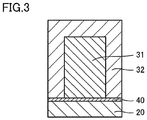
- Fig. 3 is a cross-sectional view of a rotary cutting blade material showing a further aspect of the present embodiment
- Fig. 4 is a perspective view of a rotary cutting blade material showing a further aspect of the present embodiment
- Fig. 5 is a perspective view of a rotary cutting blade obtained from the rotary cutting blade material in the present embodiment.
- a rotary cutting blade material 1 in the present embodiment is a material for a rotary cutting blade attached to a shank 5 for use.
- rotary cutting blade material 1 in the present embodiment has an attaching structure forming portion 20 that is to serve as an attaching portion 2 to shank 5, a cutting structure forming portion 30 that is to serve as a cutting blade, and a joint portion 40.
- attaching portion 2 is obtained from attaching structure forming portion 20 and a cutting portion 3 is obtained from cutting structure forming portion 30, and thus, a rotary cutting blade (cutting head) 10, which has cutting portion 3 and attaching portion 2, and is attached to shank 5 by attaching portion 2 for use, is obtained from rotary cutting blade material 1.
- Attaching structure forming portion 20 serves as attaching portion 2 for attachment to shank 5 in rotary cutting blade 10 obtained by processing rotary cutting blade material 1 described above ( Fig. 5 ).
- attaching portion 2 subjected to cutting processing or grinding processing to be processed into a prescribed shape of a thread groove, a pin hole or the like is formed in attaching structure forming portion 20.
- attaching structure forming portion 20 itself may serve as attaching portion 2, or may be processed into a prescribed shape as needed to serve as attaching portion 2.
- a shape and a size of attaching structure forming portion 20 are selected such that cutting processing or grinding processing for forming a structure for mechanical fastening such as screw fastening, pinning, other type of engagement, and press fitting can be performed, or such that brazing to shank 5 can be performed.
- attaching structure forming portion 20 in the present embodiment has such a cylindrical shape that a joint surface of attaching structure forming portion 20 to cutting structure forming portion 30 has a circular shape identical to that of a joint surface of cutting structure forming portion 30 to attaching structure forming portion 20.
- Fig. 1A shows cylindrical attaching structure forming portion 20 having the circular joint surface
- the shape of attaching structure forming portion 20 is not limited to the cylindrical shape and may be any shape such as an elliptic cylindrical shape, a polygonal prism shape including a triangular prism shape, a quadrangular prism shape and the like, a conical shape, and a polygonal pyramid shape.
- Fig. 1B shows attaching structure forming portion 20 having a rectangular longitudinal cross section (which is a cross section in a direction perpendicular to the joint surface to cutting structure forming portion 30, and corresponds to a cross section taken along line A-A in Fig.
- the shape of the longitudinal cross section is not limited thereto and may be any shape such as a trapezoidal shape and a triangular shape.
- the joint surface of attaching structure forming portion 20 may have a shape and a size identical to those of the joint surface of cutting structure forming portion 30 as shown in Fig. 1B , or may have a shape and a size different from those of the joint surface of cutting structure forming portion 30 as shown in, for example, Fig. 4 .
- a height (a length in the direction perpendicular to the joint surface to cutting structure forming portion 30) of attaching structure forming portion 20 is not particularly limited as long as attaching structure forming portion 20 has a height that allows cutting processing or grinding processing for forming a structure for mechanical fastening, a height that allows brazing, and a height that allows a vibration reducing effect to be offered in attaching portion 2 obtained by processing attaching structure forming portion 20.
- a diameter of the joint surface may be set to 5 mm to 30 mm and a height of attaching structure forming portion 20 may be set to 1 mm to 20 mm.
- Attaching structure forming portion 20 is made of a hard material including a hard component and at least one element selected from an iron group element.
- the hard component is at least one selected from the group consisting of W (tungsten), WC (tungsten carbide), TiC (titanium carbide), TiCN (titanium carbonitride), Al 2 O 3 (alumina), and a combination of at least one of CBN (cubic boron nitride) and diamond and at least one of W and WC.
- the iron group element is any one of cobalt, iron and nickel.
- the iron group element serves as a sintering aid used to form a sintered material from the hard component.
- the hard material preferably includes W (tungsten) of the above-described hard component, and preferably includes at least one of iron and nickel of the above-described iron group element.
- the hard material may include another component such as copper as a component other than the above-described hard component and the above-described iron group element.
- a content of the hard component included in the hard material is preferably not lower than 50% by mass, more preferably not lower than 80% by mass, and further preferably not lower than 90% by mass, with respect to a total mass of the hard material.
- a total content of iron, nickel and cobalt included in the hard material is preferably not higher than 50% by mass, more preferably not higher than 20% by mass, and further preferably not higher than 10% by mass, with respect to the total mass of the hard material.
- the hardness of attaching structure forming portion 20 can be made lower than that of a core portion 31 including a cemented carbide material and a surface portion 32 including PCD (polycrystalline diamond) or CBN (cubic boron nitride), and thus, the excellent free-cuttability can be provided to attaching structure forming portion 20.
- attaching structure forming portion 20 for screw fastening, pinning and other type of engagement can be facilitated.
- W tungsten
- the brazing wettability of attaching portion 2 can be improved at the time of processing attaching structure forming portion 20 into attaching portion 2 and brazing attaching portion 2 to shank 5.
- attaching structure forming portion 20 includes the hard material having the specific properties
- attaching portion 2 formed from attaching structure forming portion 20 produces the vibration reducing effect of suppressing chatter and breakage when rotary cutting blade 10 is attached to shank 5 for use, and thus, the service life of rotary cutting blade 10 can be improved.
- attaching structure forming portion 20 includes the hard material having the specific properties, the rigidity of attaching structure forming portion 20 can be made smaller than that of core portion 31 including the cemented carbide material and surface portion 32 including PCD or CBN.
- attaching portion 2 to shank 5 formed from attaching structure forming portion 20 is also likely to elastically deform. Therefore, a load applied to above-described attaching portion 2 when rotary cutting blade 10 is used as a rotary cutting tool can be reduced, and thus, breakage of rotary cutting blade 10 can be suppressed.
- attaching portion 2 of rotary cutting blade 10 is easily affected by vibrations when rotary cutting blade 10 is used as a rotary cutting tool.
- attaching portion 2 is made of a material that is likely to deform as described above, attaching portion 2 is likely to absorb the vibrations, and thus, a rotary cutting tool with reduced chatter and excellent vibration reducing property (anti-vibration property) can be provided.
- the hard material a material having a Young's modulus of less than 500 GPa at the temperature of 25°C
- the above-described Young's modulus is a value measured in accordance with a tensile test.
- attaching structure forming portion 20 and core and surface portions 31 and 32 that form cutting structure forming portion 30 are integrated by sintering.
- the present inventors have found that in the case of using attaching structure forming portion 20 including the hard material, core portion 31 including the cemented carbide material, and surface portion 32 including PCD or CBN, the joining property between attaching structure forming portion 20 and core and surface portions 31 and 32 during sintering may in some cases decrease when the integration is performed by sintering as described above.
- a cause of this is estimated as follows. Specifically, due to temperature change during sintering, deformation (thermal expansion) occurs in each of attaching structure forming portion 20, core portion 31 and surface portion 32.
- the degree of deformation of attaching structure forming portion 20, core portion 31 and surface portion 32 varies depending on a difference in material forming each portion.
- the hard material forming attaching structure forming portion 20 is more likely to deform than the cemented carbide material forming core portion 31 and the material including PCD or CBN forming surface portion 32. Such a difference in deformation during sintering is likely to cause a reduction in joining property between attaching structure forming portion 20 and core and surface portions 31 and 32 during sintering.
- the present inventors have found that adjustment of an elongation of the above-described hard material makes it possible to suppress the reduction in joining property during sintering.
- the elongation of the above-described hard material is preferably not more than 5%, more preferably not more than 1%, and further preferably not more than 0.5%.
- the plastic deformability of attaching structure forming portion 20 made of the above-described hard material can be reduced.
- deformation of attaching structure forming portion 20 caused by temperature change during sintering is reduced, and thus, the difference in deformation between attaching structure forming portion 20 and core and surface portions 31 and 32 of cutting structure forming portion 30 during sintering can be reduced.
- the above-described elongation is a value measured in accordance with a tensile test.
- attaching structure forming portion 20 in the present embodiment is formed using the hard material including the hard component and the iron group element and having the specific properties, and thus, cutting processing or grinding processing for mechanical fastening for attachment to shank 5, and brazing for attachment to shank 5 can be facilitated.
- the vibration reducing effect of suppressing chatter and breakage when rotary cutting blade 10 is attached to shank 5 for use can be obtained.
- the excellent joining property between attaching structure forming portion 20 and core and surface portions 31 and 32 of cutting structure forming portion 30 during sintering can also be achieved.
- the Young's modulus and the elongation of the hard material can be adjusted in accordance with the type and the content of the hard component and the iron group element in the hard material.
- Cutting structure forming portion 30 is processed to form cutting portion 3 having the cutting blade in rotary cutting blade 10 obtained by processing rotary cutting blade material 1 ( Fig. 5 ).
- cutting structure forming portion 30 in the present embodiment has a cylindrical shape.
- a size of a bottom surface of the cylinder and a height of the cylinder forming cutting structure forming portion 30 are not particularly limited as long as cutting portion 3 having the cutting blade can be formed by cutting processing or grinding processing.
- a diameter of the bottom surface may be set to 5 mm to 30 mm and the height may be set to 5 mm to 30 mm.
- Fig. 1A shows cylindrical cutting structure forming portion 30, the shape of cutting structure forming portion 30 is not limited to the cylindrical shape and may be any shape such as an elliptic cylindrical shape, a polygonal prism shape including a triangular prism shape, a quadrangular prism shape and the like, a conical shape, and a polygonal pyramid shape.
- Fig. 1B shows cutting structure forming portion 30 having a rectangular longitudinal cross section (which is a cross section in a direction perpendicular to the joint surface to attaching structure forming portion 20, and corresponds to a cross section taken along line A-A in Fig. 1A ), the shape of the longitudinal cross section is not limited thereto and may be any shape such as a trapezoidal shape and a triangular shape.
- the joint surface of cutting structure forming portion 30 to attaching structure forming portion 20 may have a shape and a size identical to or different from those of the joint surface of attaching structure forming portion 20.
- Cutting structure forming portion 30 in the present embodiment has core portion 31 and surface portion 32 provided on attaching structure forming portion 20 with joint portion 40 being interposed.
- Surface portion 32 covers a part of a surface of the core portion. Specifically, as shown in Fig. 1B , surface portion 32 is provided to cover at least a part of the surface of core portion 31 other than the surface that is in contact with joint portion 40. In the portion where surface portion 32 covers core portion 31, core portion 31 and surface portion 32 are joined by sintering described below.
- a size of each of core portion 31 and surface portion 32 may be selected such that the desired cutting blade can be formed by cutting processing or grinding processing, and a diameter of a bottom surface and a height of each of core portion 31 and surface portion 32 may be selected in consideration of a size and a shape of the formed cutting blade, and a size required for joining to attaching structure forming portion 20.
- the diameter of the bottom surface of core portion 31 may be set to 3 mm to 27 mm and the height of core portion 31 may be set to 5 mm to 30 mm.
- an outer diameter of the bottom surface of surface portion 32 may be set to 5 mm to 30 mm and the height of surface portion 32 may be set to 5 mm to 30 mm.
- core portion 31 in the present embodiment is provided in a central portion of cutting structure forming portion 30 and has a solid cylindrical shape.
- Figs. 1A and 1B show solid cylindrical core portion 31, the shape of core portion 31 is not limited to the cylindrical shape and may be any shape such as an elliptic cylindrical shape, a polygonal prism shape including a triangular prism shape, a quadrangular prism shape and the like, a conical shape, and a polygonal pyramid shape.
- Core portion 31 may have a solid shape or a hollow shape.
- a hollow portion formed in core portion 31 may be shaped to penetrate from a surface of core portion 31 on a side where core portion 31 is joined to attaching structure forming portion 20 to a surface of core portion 31 on a side opposite to the side where core portion 31 is joined to attaching structure forming portion 20, or may be shaped to penetrate only to one of these surfaces, or may be shaped not to penetrate to any of these surfaces.
- an inner core portion 33 made of the hard material forming attaching structure forming portion 20 or any material such as steel different from the materials forming core portion 31 and attaching structure forming portion 20 may be provided in the hollow portion of core portion 31 as shown in Fig. 2A .
- How to provide inner core portion 33 is not particularly limited.
- inner core portion 33 having a shape identical to that of the hollow portion of core portion 31 may be fixed to the above-described hollow portion by screw-in, shrinkage fitting or brazing.
- inner core portion 33 may be shaped like a pin having a thread groove at a tip end of inner core portion 33 on the attaching structure forming portion 20 side such that inner core portion 33 and attaching structure forming portion 20 are fixed by a fixture such as a screw or a pin.
- the other tip end of inner core portion 33 is formed to have a shape of a head of the screw or the pin.
- inner core portion 33 made of a material identical to the hard material forming attaching structure forming portion 20 When inner core portion 33 made of a material identical to the hard material forming attaching structure forming portion 20 is arranged in the hollow portion of core portion 31, inner core portion 33 provided in the hollow portion of core portion 31 and attaching structure forming portion 20 may be integrally formed, and attaching structure forming portion 20 and cutting structure forming portion 30 may be assembled such that inner core portion 33 is arranged in the hollow portion of core portion 31, as shown in Fig. 2C .
- inner core portion 33 made of the material identical to the hard material forming attaching structure forming portion 20 is formed integrally with attaching structure forming portion 20 as described above, the vibration reducing property of obtained rotary cutting blade 10 can be further improved.
- Figs. 1B and 2A to 2C show core portion 31 and inner core portion 33 each having a rectangular longitudinal cross section (which is a cross section in the direction perpendicular to the joint surface to attaching structure forming portion 20, and corresponds to a cross section taken along line A-A in Fig. 1A ).
- core portion 31 and inner core portion 33 may have an identical longitudinal cross-sectional shape or different longitudinal cross-sectional shapes, and the shape of the longitudinal cross section may be any shape such as a trapezoidal shape and a triangular shape.
- Core portion 31 is made of a cemented carbide material.
- the cemented carbide material is, for example, a material including tungsten carbide and cobalt. Since the cemented carbide material is used for core portion 31, the hardness of core portion 31 can be made lower than that of surface portion 32 made of PCD or CBN. As a result, the hardness of cutting structure forming portion 30 having above-described core portion 31 can be made lower than the hardness in the case of forming cutting structure forming portion 30 as a whole from PCD or CBN only. Therefore, cutting processing and grinding processing for forming the cutting blade can be facilitated, and cutting structure forming portion 30 excellent in processability of the cutting blade can be provided.
- cemented carbide material is used for core portion 31, an excellent joined state of core portion 31 and surface portion 32 including PCD or CBN can be obtained when a molded body of core portion 31 and a molded body of surface portion 32 are assembled and sintered as described below.
- a content ratio between tungsten carbide and cobalt included in the cemented carbide material forming core portion 31 is not particularly limited.
- a content of tungsten carbide is preferably not lower than 75% by mass, and more preferably not lower than 85% by mass, with respect to a total mass of tungsten carbide and cobalt.
- the content of tungsten carbide is preferably not higher than 98% by mass, and more preferably not higher than 95% by mass, with respect to the total mass of tungsten carbide and cobalt.
- the strength of the core portion can be ensured.
- excellent joining to surface portion 32 can be achieved.
- the cemented carbide material may include a component other than tungsten carbide and cobalt.
- the other component can include one or two or more types of TiC, TaC, Ni and the like.
- a content of the other component is preferably not higher than 10% by mass, and more preferably not higher than 5% by mass, with respect to a total mass of the cemented carbide material.
- surface portion 32 in the present embodiment has a cylindrical shape having a hollow portion that accommodates above-described core portion 31 in the center.
- surface portion 32 is joined to attaching structure forming portion 20 and is concentrically provided on an outer circumference of a side surface of cylindrical core portion 31, to thereby form cutting structure forming portion 30 having a cylindrical shape as a whole, together with core portion 31.
- surface portion 32 is joined to core portion 31 by sintering described below.
- Surface portion 32 has a joint surface joined to the attaching structure forming portion, and is provided to cover at least a part of the surface of core portion 31.
- surface portion 32 may be provided only on a side surface portion of the surface of core portion 31 as shown in Figs. 1B and 2A to 2C , or may be provided on the side surface and a top surface of core portion 31 such that the surface of core portion 31 is not exposed to the outside as shown in Fig. 3 .
- rotary cutting blade 10 having the cutting blade formed on surface portion 32 can also be manufactured at a tip end portion of cutting portion 3.
- a shape and a size of surface portion 32 are not particularly limited as long as surface portion 32 can be joined to core portion 31 and the cutting blade can be formed by performing cutting processing or grinding processing on cutting structure forming portion 30. Therefore, surface portion 32 may be formed to have an outer shape different from that of core portion 31, and an outer shape of cutting structure forming portion 30 may be formed into any shape such as an elliptic cylindrical shape, a polygonal prism shape including a triangular prism shape, a quadrangular prism shape and the like, a conical shape, and a polygonal pyramid shape. Cutting processing or grinding processing for forming the cutting blade may be performed only on surface portion 32, or may be performed on both surface portion 32 and core portion 31.
- Surface portion 32 is made of a material including PCD (polycrystalline diamond) or CBN (cubic boron nitride). Since surface portion 32 is made of the material including PCD or CBN, a rotary cutting tool excellent in wear resistance and breakage resistance can be formed. Surface portion 32 is preferably made of a material including CBN.
- Joint portion 40 is formed on a joint surface between attaching structure forming portion 20 and cutting structure forming portion 30.
- Joint portion 40 has at least a first joint portion that joins the joint surface of attaching structure forming portion 20 and core portion 31 of cutting structure forming portion 30, and a second joint portion that joins the joint surface of attaching structure forming portion 20 and surface portion 32 of cutting structure forming portion 30.
- a thickness of joint portion 40 is not particularly limited as long as a necessary joining strength is obtained.
- the thickness of joint portion 40 may be set to 5 ⁇ m to 200 ⁇ m.
- joint portion 40 By providing joint portion 40, attaching structure forming portion 20 and cutting structure forming portion 30 can be joined firmly.
- the strength of joint portion 40 measured in accordance with a shear test is preferably not less than 25 kgf/mm 2 , and preferably not less than 30 kgf/mm 2 .
- joint portion 40 may be made of a material including one or two or more types of iron group elements composed of cobalt, iron and nickel. Since the second joint portion of the joint portion that joins attaching structure forming portion 20 and surface portion 32 is a joint portion made of the material including one or two or more types of iron group elements, the joining property between attaching structure forming portion 20 and surface portion 32 of cutting structure forming portion 30 can be improved.
- Joint portion 40 may be formed by sintering attaching structure forming portion 20 and cutting structure forming portion 30. Specifically, during sintering, attaching structure forming portion 20 and core portion 31 of cutting structure forming portion 30 can form joint portion 40 due to the iron group element included in attaching structure forming portion 20 and a small amount of cobalt component included in core portion 31.
- joint portion 40 can also be formed between attaching structure forming portion 20 and surface portion 32 during sintering.
- surface portion 32 includes CBN, it is preferable to provide joint portion 40 including the above-described iron group element. As a result, surface portion 32 including CBN and attaching structure forming portion 20 can be joined at a joining strength of not less than 30 kgf/mm 2 .
- Joint portion 40 may include both the joint portion made of a material including one or two or more types of iron group elements and the joint portion formed by sintering, or may include only one of these joint portions.
- the first joint portion that joins attaching structure forming portion 20 and core portion 31 may be formed by sintering
- the second joint portion that joins attaching structure forming portion 20 and surface portion 32 may be made of the material including one or two or more types of iron group elements.
- the rotary cutting blade material in the present embodiment is manufactured through an assembling step of forming a first precursor that is to serve as attaching structure forming portion 20, a second precursor that is to serve as core portion 31, and a third precursor that is to serve as surface portion 32, and assembling these first to third precursors, and a sintering step of sintering a precursor of the rotary cutting blade material assembled in the assembling step.
- Each of the precursors of attaching structure forming portion 20, core portion 31 and surface portion 32 can be manufactured in accordance with a conventionally known method, and a molded body obtained by putting a raw material powder into a mold and performing press molding, or a blank workpiece obtained by processing a blank member and the like of each material into a prescribed shape by cutting processing or grinding processing can, for example, be used. Since each precursor contracts by sintering, it is preferable to prepare the mold for forming the molded body and the blank workpiece that are sized to take into account the degree of contraction of each precursor.
- the precursor of core portion 31 is fitted by push-in into a hollow portion of the precursor of surface portion 32 obtained as described above, to thereby form a precursor that is to serve as cutting structure forming portion 30.
- the precursor that is to serve as cutting structure forming portion 30 is assembled such that the precursor of core portion 31 and the precursor of surface portion 32 are arranged to be in contact with the precursor of attaching structure forming portion 20, to thereby obtain a precursor of the rotary cutting blade material, and this precursor is sintered.
- core portion 31 and surface portion 32 are joined, and joint portion 40 including cobalt is formed between core portion 31 and attaching structure forming portion 20.
- joint portion 40 including cobalt is formed between surface portion 32 and attaching structure forming portion 20.
- the precursor of core portion 31 and the precursor of surface portion 32 are arranged on the precursor of attaching structure forming portion 20, with a material including one or two or more types of iron group elements composed of nickel, iron and cobalt being interposed, during assembling of the above-described precursors, and then, sintering is performed, joint portion 40 including the above-described iron group element is formed.
- the material including the iron group element may be arranged between the precursors in the form of powder or in the form of foil.
- the sintering step may be performed under the conventionally known conditions.
- different materials are used for attaching structure forming portion 20, core portion 31 and surface portion 32, and thus, the degree of deformation during sintering varies. Due to this difference in deformation, a crack may occur in a portion where the molded bodies of attaching structure forming portion 20, core portion 31 and surface portion 32 are in contact with one another.
- sintering is performed under the conditions that a pressure is 4.5 GPa to 7.5 GPa and a temperature is 1200 to 1700°C, and thereafter, with the temperature being maintained, the pressure is reduced to 3 GPa to 4 GPa to release compression of core portion 31, and then, the pressure is set to ordinary pressure and the temperature is set to ordinary temperature.
- a crack does not occur in the portion where the molded bodies are in contact with one another, and thus, the excellent joining property can be obtained in the portion where the molded bodies are in contact with one another.
- the rotary cutting blade material in the present disclosure can be suitably used as rotary cutting blade 10 of a rotary cutting tool such as a drill and an end mill as shown in Fig. 5 .
- a test piece of a strip shape having a length of 30 mm and a width of 5 mm was prepared, and this test piece was subjected to a tensile test at a tensile speed of 0.1 mm/min using Autograph (manufactured by Shimadzu Corporation), to thereby measure a Young's modulus and an elongation in accordance with a strain gauge method.
- die steel was cut at a cutting speed V of 600 m/min, a feed amount fz of 0.1 mm, a cutting amount Ae of 0.2 mm, and Ap of 2.5 mm, to thereby evaluate vibrations with a vibrometer (manufactured by KEYENCE).
- die steel was cut at a cutting speed V of 600 m/min, a feed amount fz of 0.3 mm, a cutting amount Ae of 0.2 mm, and Ap of 2.5 mm, to thereby evaluate the presence or absence of breakage of the rotary cutting blade (cutting head).
- each of cylindrical attaching structure forming portion 20, cylindrical core portion 31 and hollow cylindrical surface portion 32 shown in Figs. 1A and 1B by sintering the powder materials described below were used and press molding was performed with a mold, to thereby obtain a molded body for the attaching structure forming portion, a molded body for the core portion, and a molded body for the surface portion.
- the molded body for the core portion was fitted by push-in into a hollow portion of the molded body for the surface portion obtained as described above, to thereby obtain a molded body for the cutting structure forming portion.
- a thin plate including 100% by mass of nickel was arranged on a joint surface of the molded body for the attaching structure forming portion in order to form joint portion 40, and the molded body for the core portion and the molded body for the surface portion were arranged on this thin plate.
- the above-described molded bodies were thus assembled.
- Rotary cutting blade material 1 thus obtained had a diameter of 8 mm and a height of 20 mm, attaching structure forming portion 20 had a height of 12 mm, core portion 31 had a diameter of 5 mm, surface portion 32 had a thickness in a circumferential direction of 1.5 mm, and core portion 31 and surface portion 32 had a height of 5 mm.
- a four-blade (torsion angle: 45°) cutting blade was formed on cutting structure forming portion 30 of obtained rotary cutting blade material 1, and a thread groove was formed in attaching structure forming portion 20 so as to be fastened to a screw of superhard shank 5 having a diameter of 7.5 mm and a length of 75 mm, to thereby obtain a rotary cutting tool.
- vibrations and breakage during the rotary cutting operation were evaluated. The result is shown in Table 1.
- a rotary cutting blade material and a rotary cutting tool were obtained similarly to Example 1, except that the cemented carbide material (Young's modulus: 620 GPa, elongation: 0.5%) used as the material of the molded body for the core portion in Example 1 was used as the material of the molded body for the attaching structure forming portion.
- Example 1 Based on comparison between Example 1 and Comparative Example 1, it became clear that when the attaching structure forming portion is made of the hard material, the excellent vibration reducing property during the rotary cutting operation can be achieved and breakage can be suppressed.
- a rotary cutting blade material and a rotary cutting tool were obtained similarly to Example 1, except that the materials described below were used as the material of the molded body for the attaching structure forming portion.
- a hard material Young's modulus: 300 GPa, elongation: 5%
- a metal binder including iron, nickel and copper
- a hard material Young's modulus: 350 GPa, elongation: 25%
- a metal binder including iron, nickel and copper
Landscapes
- Engineering & Computer Science (AREA)
- Mechanical Engineering (AREA)
- Chemical & Material Sciences (AREA)
- Materials Engineering (AREA)
- Manufacturing & Machinery (AREA)
- Metallurgy (AREA)
- Organic Chemistry (AREA)
- Composite Materials (AREA)
- Cutting Tools, Boring Holders, And Turrets (AREA)
- Drilling Tools (AREA)
- Powder Metallurgy (AREA)
- Pressure Welding/Diffusion-Bonding (AREA)
Abstract
Description
- The present invention relates to a rotary cutting blade material and a method for manufacturing the same. The present application claims the priority based on Japanese Patent Application No.
2016-199278 - Japanese National Patent Publication No.
2015-520661 - PTD 1: Japanese National Patent Publication No.
2015-520661 - A rotary cutting blade material according to one aspect of the present disclosure is a rotary cutting blade material for a rotary cutting blade attached to a shank for use, the rotary cutting blade material having an attaching structure forming portion that is to serve as an attaching portion to the shank, a cutting structure forming portion that is to serve as a cutting blade, and a joint portion, the cutting structure forming portion having a core portion and a surface portion provided on the attaching structure forming portion with the joint portion being interposed, the surface portion covering at least a part of a surface of the core portion, the attaching structure forming portion including a hard material including a hard component and one or two or more types of iron group elements, the hard material having a Young's modulus of not more than 350 GPa, the core portion including a cemented carbide material, the surface portion including PCD (polycrystalline diamond) or CBN (cubic boron nitride), the hard component being at least one selected from the group consisting of W (tungsten), WC (tungsten carbide), TiC (titanium carbide), TiCN (titanium carbonitride), Al2O3 (alumina), and a combination of at least one of CBN (cubic boron nitride) and diamond and at least one of W and WC.
- A method for manufacturing the rotary cutting blade material according to another aspect of the present disclosure has: an assembling step of assembling a precursor of the rotary cutting blade material by using a first precursor for forming the attaching structure forming portion, a second precursor for forming the core portion, and a third precursor for forming the surface portion; and a sintering step of sintering the precursor of the rotary cutting blade material.
-
-
Fig. 1A is a perspective view of a rotary cutting blade material showing one aspect of the present embodiment. -
Fig. 1B is a cross-sectional view taken along line A-A inFig. 1A . -
Fig. 2A is a cross-sectional view of a rotary cutting blade material showing another aspect of the present embodiment. -
Fig. 2B is a cross-sectional view of a rotary cutting blade material showing still another aspect of the present embodiment. -
Fig. 2C is a cross-sectional view of a rotary cutting blade material showing a further aspect of the present embodiment. -
Fig. 3 is a cross-sectional view of a rotary cutting blade material showing a further aspect of the present embodiment. -
Fig. 4 is a perspective view of a rotary cutting blade material showing a further aspect of the present embodiment. -
Fig. 5 is a perspective view of a rotary cutting blade obtained from the rotary cutting blade material in the present embodiment. - A cutting blade of a rotary cutting tool such as a drill and an end mill is worn out when used. Therefore, after the cutting performance decreases or a prescribed period of use elapses, a cutting head including at least the cutting blade is replaced with a new cutting head. At this time, if the cutting head is attached to a superhard shank in a non-removable manner, the superhard shank must be replaced together at the timing of replacement of the cutting blade, even when replacement of the superhard shank is unnecessary because the superhard shank does not reach the end of the service life. Such replacement of the superhard shank is not preferable in terms of cost because the superhard shank is relatively expensive. Thus, it is conceivable to removably attach the cutting head to the superhard shank so as to be able to replace only the cutting head when the cutting blade is worn out.
- However, the construction described in PTD 1 has room for further improvement in formation of the attaching means for attaching the construction to the tool carrier and brazing.
- The present disclosure has been made in light of the above-described circumstances, and an object of the present disclosure is to provide a rotary cutting blade material excellent in attachability to a shank, and a method for manufacturing the same.
- According to the present disclosure, there can be provided a rotary cutting blade material excellent in attachability to a shank, and a method for manufacturing the same.
- First, an embodiment of the present invention will be listed and described.
- [1] A rotary cutting blade material according to one aspect of the present invention is a rotary cutting blade material for a rotary cutting blade attached to a shank for use, the rotary cutting blade material having an attaching structure forming portion that is to serve as an attaching portion to the shank, a cutting structure forming portion that is to serve as a cutting blade, and a joint portion, the cutting structure forming portion having a core portion and a surface portion provided on the attaching structure forming portion with the joint portion being interposed, the surface portion covering at least a part of a surface of the core portion, the attaching structure forming portion including a hard material including a hard component and one or two or more types of iron group elements, the hard material having a Young's modulus of not more than 350 GPa, the core portion including a cemented carbide material, the surface portion including PCD (polycrystalline diamond) or CBN (cubic boron nitride), the hard component being at least one selected from the group consisting of W (tungsten), WC (tungsten carbide), TiC (titanium carbide), TiCN (titanium carbonitride), Al2O3 (alumina), and a combination of at least one of CBN (cubic boron nitride) and diamond and at least one of W and WC.
- [2] The surface portion covers the core portion such that the core portion is not exposed to the outside.
- [3] In the rotary cutting blade material, at least a part of the joint portion includes one or two or more types of iron group elements.
- [4] In the rotary cutting blade material, a portion of the joint portion between the attaching structure forming portion and the surface portion includes one or two or more types of iron group elements.
- [5] In the rotary cutting blade material, the core portion has a hollow portion therein, and the attaching structure forming portion has an inner core portion arranged in the hollow portion.
- [6] In the rotary cutting blade material, the hard material has a Young's modulus of less than 300 GPa.
- [7] In the rotary cutting blade material, the hard material has an elongation of not more than 5%.
- [8] The rotary cutting blade material is a rotary cutting blade material for a rotary cutting blade attached to a shank for use, the rotary cutting blade material having an attaching structure forming portion that is to serve as an attaching portion to the shank, a cutting structure forming portion that is to serve as a cutting blade, and a joint portion, the cutting structure forming portion having a core portion and a surface portion provided on the attaching structure forming portion with the joint portion being interposed, the surface portion covering at least a part of a surface of the core portion, the attaching structure forming portion including a hard material including W (tungsten), iron and nickel, the hard material having a Young's modulus of less than 300 GPa and an elongation of less than 5%, the core portion including a cemented carbide material, the surface portion including CBN (cubic boron nitride), a portion of the joint portion between the attaching structure forming portion and the surface portion being a material including one or two or more types of iron group elements.
- [9] A method for manufacturing the rotary cutting blade material according to another aspect of the present invention has: an assembling step of assembling a precursor of the rotary cutting blade material by using a first precursor for forming the attaching structure forming portion, a second precursor for forming the core portion, and a third precursor for forming the surface portion; and a sintering step of sintering the precursor of the rotary cutting blade material.
- [10] In the method for manufacturing the rotary cutting blade material, in the assembling step, the second precursor and the third precursor are arranged on the first precursor with a material including one or two or more types of iron group elements being interposed.
- A specific example of a rotary cutting blade material and a method for manufacturing the same according to the present embodiment will be described hereinafter with reference to the drawings.
Fig. 1A is a perspective view of a rotary cutting blade material showing one aspect of the present embodiment, andFig. 1B is a cross-sectional view taken along line A-A inFig. 1A .Fig. 2 is a cross-sectional view of a rotary cutting blade material showing another aspect of the present embodiment.Fig. 3 is a cross-sectional view of a rotary cutting blade material showing a further aspect of the present embodiment.Fig. 4 is a perspective view of a rotary cutting blade material showing a further aspect of the present embodiment.Fig. 5 is a perspective view of a rotary cutting blade obtained from the rotary cutting blade material in the present embodiment. - A rotary cutting blade material 1 in the present embodiment is a material for a rotary cutting blade attached to a
shank 5 for use. As shown inFigs. 1A and 1B , rotary cutting blade material 1 in the present embodiment has an attachingstructure forming portion 20 that is to serve as an attaching portion 2 toshank 5, a cuttingstructure forming portion 30 that is to serve as a cutting blade, and ajoint portion 40. As shown inFig. 5 , attaching portion 2 is obtained from attachingstructure forming portion 20 and acutting portion 3 is obtained from cuttingstructure forming portion 30, and thus, a rotary cutting blade (cutting head) 10, which has cuttingportion 3 and attaching portion 2, and is attached toshank 5 by attaching portion 2 for use, is obtained from rotary cutting blade material 1. - Attaching
structure forming portion 20 serves as attaching portion 2 for attachment toshank 5 inrotary cutting blade 10 obtained by processing rotary cutting blade material 1 described above (Fig. 5 ). Whenrotary cutting blade 10 is attached toshank 5 by mechanical fastening such as screw fastening, pinning, other type of engagement, and press fitting, attaching portion 2 subjected to cutting processing or grinding processing to be processed into a prescribed shape of a thread groove, a pin hole or the like is formed in attachingstructure forming portion 20. Whenrotary cutting blade 10 is attached toshank 5 by brazing, attachingstructure forming portion 20 itself may serve as attaching portion 2, or may be processed into a prescribed shape as needed to serve as attaching portion 2. - A shape and a size of attaching
structure forming portion 20 are selected such that cutting processing or grinding processing for forming a structure for mechanical fastening such as screw fastening, pinning, other type of engagement, and press fitting can be performed, or such that brazing toshank 5 can be performed. - As shown in
Fig. 1A , attachingstructure forming portion 20 in the present embodiment has such a cylindrical shape that a joint surface of attachingstructure forming portion 20 to cuttingstructure forming portion 30 has a circular shape identical to that of a joint surface of cuttingstructure forming portion 30 to attachingstructure forming portion 20. - Although
Fig. 1A shows cylindrical attachingstructure forming portion 20 having the circular joint surface, the shape of attachingstructure forming portion 20 is not limited to the cylindrical shape and may be any shape such as an elliptic cylindrical shape, a polygonal prism shape including a triangular prism shape, a quadrangular prism shape and the like, a conical shape, and a polygonal pyramid shape. AlthoughFig. 1B shows attachingstructure forming portion 20 having a rectangular longitudinal cross section (which is a cross section in a direction perpendicular to the joint surface to cuttingstructure forming portion 30, and corresponds to a cross section taken along line A-A inFig. 1A ), the shape of the longitudinal cross section is not limited thereto and may be any shape such as a trapezoidal shape and a triangular shape. In addition, the joint surface of attachingstructure forming portion 20 may have a shape and a size identical to those of the joint surface of cuttingstructure forming portion 30 as shown inFig. 1B , or may have a shape and a size different from those of the joint surface of cuttingstructure forming portion 30 as shown in, for example,Fig. 4 . - A height (a length in the direction perpendicular to the joint surface to cutting structure forming portion 30) of attaching
structure forming portion 20 is not particularly limited as long as attachingstructure forming portion 20 has a height that allows cutting processing or grinding processing for forming a structure for mechanical fastening, a height that allows brazing, and a height that allows a vibration reducing effect to be offered in attaching portion 2 obtained by processing attachingstructure forming portion 20. For example, in attachingstructure forming portion 20 having the shape shown inFig. 1A , a diameter of the joint surface may be set to 5 mm to 30 mm and a height of attachingstructure forming portion 20 may be set to 1 mm to 20 mm. - Attaching
structure forming portion 20 is made of a hard material including a hard component and at least one element selected from an iron group element. The hard component is at least one selected from the group consisting of W (tungsten), WC (tungsten carbide), TiC (titanium carbide), TiCN (titanium carbonitride), Al2O3 (alumina), and a combination of at least one of CBN (cubic boron nitride) and diamond and at least one of W and WC. The iron group element is any one of cobalt, iron and nickel. The iron group element serves as a sintering aid used to form a sintered material from the hard component. - The hard material preferably includes W (tungsten) of the above-described hard component, and preferably includes at least one of iron and nickel of the above-described iron group element.
- The hard material may include another component such as copper as a component other than the above-described hard component and the above-described iron group element.
- A content of the hard component included in the hard material is preferably not lower than 50% by mass, more preferably not lower than 80% by mass, and further preferably not lower than 90% by mass, with respect to a total mass of the hard material. A total content of iron, nickel and cobalt included in the hard material is preferably not higher than 50% by mass, more preferably not higher than 20% by mass, and further preferably not higher than 10% by mass, with respect to the total mass of the hard material.
- When at least one hard component selected from the group consisting of W (tungsten), WC (tungsten carbide), TiC (titanium carbide), TiCN (titanium carbonitride), Al2O3 (alumina), and a combination of at least one of CBN (cubic boron nitride) and diamond and at least one of W and WC is used as the hard component of attaching
structure forming portion 20, the hardness of attachingstructure forming portion 20 can be made lower than that of acore portion 31 including a cemented carbide material and asurface portion 32 including PCD (polycrystalline diamond) or CBN (cubic boron nitride), and thus, the excellent free-cuttability can be provided to attachingstructure forming portion 20. As a result, cutting processing or grinding processing performed on attachingstructure forming portion 20 for screw fastening, pinning and other type of engagement can be facilitated. When W (tungsten) that is a metal material is used as the above-described hard component, the brazing wettability of attaching portion 2 can be improved at the time of processing attachingstructure forming portion 20 into attaching portion 2 and brazing attaching portion 2 toshank 5. - The present inventors have newly found that since attaching
structure forming portion 20 includes the hard material having the specific properties, attaching portion 2 formed from attachingstructure forming portion 20 produces the vibration reducing effect of suppressing chatter and breakage whenrotary cutting blade 10 is attached toshank 5 for use, and thus, the service life ofrotary cutting blade 10 can be improved. - A reason for this is estimated as follows. Since attaching
structure forming portion 20 includes the hard material having the specific properties, the rigidity of attachingstructure forming portion 20 can be made smaller than that ofcore portion 31 including the cemented carbide material andsurface portion 32 including PCD or CBN. As a result, whenrotary cutting blade 10 is obtained using the rotary cutting blade material in the present embodiment, attaching portion 2 toshank 5 formed from attachingstructure forming portion 20 is also likely to elastically deform. Therefore, a load applied to above-described attaching portion 2 whenrotary cutting blade 10 is used as a rotary cutting tool can be reduced, and thus, breakage ofrotary cutting blade 10 can be suppressed. - In addition, attaching portion 2 of
rotary cutting blade 10 is easily affected by vibrations whenrotary cutting blade 10 is used as a rotary cutting tool. However, when attaching portion 2 is made of a material that is likely to deform as described above, attaching portion 2 is likely to absorb the vibrations, and thus, a rotary cutting tool with reduced chatter and excellent vibration reducing property (anti-vibration property) can be provided. - In order to form such attaching
structure forming portion 20, it is preferable to use, as the hard material, a material having a Young's modulus of less than 500 GPa at the temperature of 25°C, it is more preferable to use, as the hard material, a material having a Young's modulus of less than 400 GPa at the temperature of 25°C, it is further preferable to use, as the hard material, a material having a Young's modulus of not more than 350 GPa at the temperature of 25°C, and it is the most preferable to use, as the hard material, a material having a Young's modulus of less than 300 GPa at the temperature of 25°C. The above-described Young's modulus is a value measured in accordance with a tensile test. - In addition, as described below, attaching
structure forming portion 20 and core andsurface portions structure forming portion 30 are integrated by sintering. The present inventors have found that in the case of using attachingstructure forming portion 20 including the hard material,core portion 31 including the cemented carbide material, andsurface portion 32 including PCD or CBN, the joining property between attachingstructure forming portion 20 and core andsurface portions - A cause of this is estimated as follows. Specifically, due to temperature change during sintering, deformation (thermal expansion) occurs in each of attaching
structure forming portion 20,core portion 31 andsurface portion 32. The degree of deformation of attachingstructure forming portion 20,core portion 31 andsurface portion 32 varies depending on a difference in material forming each portion. The hard material forming attachingstructure forming portion 20 is more likely to deform than the cemented carbide material formingcore portion 31 and the material including PCD or CBN formingsurface portion 32. Such a difference in deformation during sintering is likely to cause a reduction in joining property between attachingstructure forming portion 20 and core andsurface portions - The present inventors have found that adjustment of an elongation of the above-described hard material makes it possible to suppress the reduction in joining property during sintering. Specifically, the elongation of the above-described hard material is preferably not more than 5%, more preferably not more than 1%, and further preferably not more than 0.5%. When the elongation of the hard material is not more than 5%, the plastic deformability of attaching
structure forming portion 20 made of the above-described hard material can be reduced. As a result, deformation of attachingstructure forming portion 20 caused by temperature change during sintering is reduced, and thus, the difference in deformation between attachingstructure forming portion 20 and core andsurface portions structure forming portion 30 during sintering can be reduced. As a result, the reduction in joining property between attachingstructure forming portion 20 andsurface portion 32 caused due to the difference in deformation between attachingstructure forming portion 20 and cuttingstructure forming portion 30 can be suppressed. The above-described elongation is a value measured in accordance with a tensile test. - As described above, attaching
structure forming portion 20 in the present embodiment is formed using the hard material including the hard component and the iron group element and having the specific properties, and thus, cutting processing or grinding processing for mechanical fastening for attachment toshank 5, and brazing for attachment toshank 5 can be facilitated. In addition, the vibration reducing effect of suppressing chatter and breakage whenrotary cutting blade 10 is attached toshank 5 for use can be obtained. Furthermore, by adjusting the elongation of the hard material, the excellent joining property between attachingstructure forming portion 20 and core andsurface portions structure forming portion 30 during sintering can also be achieved. - The Young's modulus and the elongation of the hard material can be adjusted in accordance with the type and the content of the hard component and the iron group element in the hard material.
- Cutting
structure forming portion 30 is processed to form cuttingportion 3 having the cutting blade inrotary cutting blade 10 obtained by processing rotary cutting blade material 1 (Fig. 5 ). As shown inFig. 1A , cuttingstructure forming portion 30 in the present embodiment has a cylindrical shape. A size of a bottom surface of the cylinder and a height of the cylinder forming cuttingstructure forming portion 30 are not particularly limited as long as cuttingportion 3 having the cutting blade can be formed by cutting processing or grinding processing. For example, in cuttingstructure forming portion 30 having the shape shown inFig. 1A , a diameter of the bottom surface may be set to 5 mm to 30 mm and the height may be set to 5 mm to 30 mm. - Although
Fig. 1A shows cylindrical cuttingstructure forming portion 30, the shape of cuttingstructure forming portion 30 is not limited to the cylindrical shape and may be any shape such as an elliptic cylindrical shape, a polygonal prism shape including a triangular prism shape, a quadrangular prism shape and the like, a conical shape, and a polygonal pyramid shape. AlthoughFig. 1B shows cuttingstructure forming portion 30 having a rectangular longitudinal cross section (which is a cross section in a direction perpendicular to the joint surface to attachingstructure forming portion 20, and corresponds to a cross section taken along line A-A inFig. 1A ), the shape of the longitudinal cross section is not limited thereto and may be any shape such as a trapezoidal shape and a triangular shape. In addition, the joint surface of cuttingstructure forming portion 30 to attachingstructure forming portion 20 may have a shape and a size identical to or different from those of the joint surface of attachingstructure forming portion 20. - Cutting
structure forming portion 30 in the present embodiment hascore portion 31 andsurface portion 32 provided on attachingstructure forming portion 20 withjoint portion 40 being interposed.Surface portion 32 covers a part of a surface of the core portion. Specifically, as shown inFig. 1B ,surface portion 32 is provided to cover at least a part of the surface ofcore portion 31 other than the surface that is in contact withjoint portion 40. In the portion wheresurface portion 32covers core portion 31,core portion 31 andsurface portion 32 are joined by sintering described below. A size of each ofcore portion 31 andsurface portion 32 may be selected such that the desired cutting blade can be formed by cutting processing or grinding processing, and a diameter of a bottom surface and a height of each ofcore portion 31 andsurface portion 32 may be selected in consideration of a size and a shape of the formed cutting blade, and a size required for joining to attachingstructure forming portion 20. For example, in cuttingstructure forming portion 30 having the shape shown inFig. 1B , the diameter of the bottom surface ofcore portion 31 may be set to 3 mm to 27 mm and the height ofcore portion 31 may be set to 5 mm to 30 mm. In addition, an outer diameter of the bottom surface ofsurface portion 32 may be set to 5 mm to 30 mm and the height ofsurface portion 32 may be set to 5 mm to 30 mm. - As shown in
Figs. 1A and 1B ,core portion 31 in the present embodiment is provided in a central portion of cuttingstructure forming portion 30 and has a solid cylindrical shape. AlthoughFigs. 1A and 1B show solidcylindrical core portion 31, the shape ofcore portion 31 is not limited to the cylindrical shape and may be any shape such as an elliptic cylindrical shape, a polygonal prism shape including a triangular prism shape, a quadrangular prism shape and the like, a conical shape, and a polygonal pyramid shape.Core portion 31 may have a solid shape or a hollow shape. - A hollow portion formed in
core portion 31 may be shaped to penetrate from a surface ofcore portion 31 on a side wherecore portion 31 is joined to attachingstructure forming portion 20 to a surface ofcore portion 31 on a side opposite to the side wherecore portion 31 is joined to attachingstructure forming portion 20, or may be shaped to penetrate only to one of these surfaces, or may be shaped not to penetrate to any of these surfaces. - When
core portion 31 has a hollow shape, aninner core portion 33 made of the hard material forming attachingstructure forming portion 20 or any material such as steel different from the materials formingcore portion 31 and attachingstructure forming portion 20 may be provided in the hollow portion ofcore portion 31 as shown inFig. 2A . How to provideinner core portion 33 is not particularly limited. For example, as shown inFig. 2A ,inner core portion 33 having a shape identical to that of the hollow portion ofcore portion 31 may be fixed to the above-described hollow portion by screw-in, shrinkage fitting or brazing. Alternatively, as shown inFig. 2B ,inner core portion 33 may be shaped like a pin having a thread groove at a tip end ofinner core portion 33 on the attachingstructure forming portion 20 side such thatinner core portion 33 and attachingstructure forming portion 20 are fixed by a fixture such as a screw or a pin. In this case, the other tip end ofinner core portion 33 is formed to have a shape of a head of the screw or the pin. - When
inner core portion 33 made of a material identical to the hard material forming attachingstructure forming portion 20 is arranged in the hollow portion ofcore portion 31,inner core portion 33 provided in the hollow portion ofcore portion 31 and attachingstructure forming portion 20 may be integrally formed, and attachingstructure forming portion 20 and cuttingstructure forming portion 30 may be assembled such thatinner core portion 33 is arranged in the hollow portion ofcore portion 31, as shown inFig. 2C . Wheninner core portion 33 made of the material identical to the hard material forming attachingstructure forming portion 20 is formed integrally with attachingstructure forming portion 20 as described above, the vibration reducing property of obtainedrotary cutting blade 10 can be further improved. -
Figs. 1B and2A to 2C show core portion 31 andinner core portion 33 each having a rectangular longitudinal cross section (which is a cross section in the direction perpendicular to the joint surface to attachingstructure forming portion 20, and corresponds to a cross section taken along line A-A inFig. 1A ). However,core portion 31 andinner core portion 33 may have an identical longitudinal cross-sectional shape or different longitudinal cross-sectional shapes, and the shape of the longitudinal cross section may be any shape such as a trapezoidal shape and a triangular shape. -
Core portion 31 is made of a cemented carbide material. The cemented carbide material is, for example, a material including tungsten carbide and cobalt. Since the cemented carbide material is used forcore portion 31, the hardness ofcore portion 31 can be made lower than that ofsurface portion 32 made of PCD or CBN. As a result, the hardness of cuttingstructure forming portion 30 having above-describedcore portion 31 can be made lower than the hardness in the case of forming cuttingstructure forming portion 30 as a whole from PCD or CBN only. Therefore, cutting processing and grinding processing for forming the cutting blade can be facilitated, and cuttingstructure forming portion 30 excellent in processability of the cutting blade can be provided. - In addition, since the cemented carbide material is used for
core portion 31, an excellent joined state ofcore portion 31 andsurface portion 32 including PCD or CBN can be obtained when a molded body ofcore portion 31 and a molded body ofsurface portion 32 are assembled and sintered as described below. - A content ratio between tungsten carbide and cobalt included in the cemented carbide material forming
core portion 31 is not particularly limited. However, a content of tungsten carbide is preferably not lower than 75% by mass, and more preferably not lower than 85% by mass, with respect to a total mass of tungsten carbide and cobalt. In addition, the content of tungsten carbide is preferably not higher than 98% by mass, and more preferably not higher than 95% by mass, with respect to the total mass of tungsten carbide and cobalt. When the content of tungsten carbide is not lower than 75% by mass with respect to the total mass of tungsten carbide and cobalt, the strength of the core portion can be ensured. When the content of tungsten carbide is not higher than 98% by mass with respect to the total mass of tungsten carbide and cobalt, excellent joining to surfaceportion 32 can be achieved. - The cemented carbide material may include a component other than tungsten carbide and cobalt. Examples of the other component can include one or two or more types of TiC, TaC, Ni and the like. A content of the other component is preferably not higher than 10% by mass, and more preferably not higher than 5% by mass, with respect to a total mass of the cemented carbide material.
- As shown in
Figs. 1A and 1B ,surface portion 32 in the present embodiment has a cylindrical shape having a hollow portion that accommodates above-describedcore portion 31 in the center. As shown inFig. 1B ,surface portion 32 is joined to attachingstructure forming portion 20 and is concentrically provided on an outer circumference of a side surface ofcylindrical core portion 31, to thereby form cuttingstructure forming portion 30 having a cylindrical shape as a whole, together withcore portion 31. In the portion wheresurface portion 32covers core portion 31,surface portion 32 is joined tocore portion 31 by sintering described below. -
Surface portion 32 has a joint surface joined to the attaching structure forming portion, and is provided to cover at least a part of the surface ofcore portion 31. Specifically,surface portion 32 may be provided only on a side surface portion of the surface ofcore portion 31 as shown inFigs. 1B and2A to 2C , or may be provided on the side surface and a top surface ofcore portion 31 such that the surface ofcore portion 31 is not exposed to the outside as shown inFig. 3 . As a result,rotary cutting blade 10 having the cutting blade formed onsurface portion 32 can also be manufactured at a tip end portion of cuttingportion 3. - A shape and a size of
surface portion 32 are not particularly limited as long assurface portion 32 can be joined tocore portion 31 and the cutting blade can be formed by performing cutting processing or grinding processing on cuttingstructure forming portion 30. Therefore,surface portion 32 may be formed to have an outer shape different from that ofcore portion 31, and an outer shape of cuttingstructure forming portion 30 may be formed into any shape such as an elliptic cylindrical shape, a polygonal prism shape including a triangular prism shape, a quadrangular prism shape and the like, a conical shape, and a polygonal pyramid shape. Cutting processing or grinding processing for forming the cutting blade may be performed only onsurface portion 32, or may be performed on bothsurface portion 32 andcore portion 31. -
Surface portion 32 is made of a material including PCD (polycrystalline diamond) or CBN (cubic boron nitride). Sincesurface portion 32 is made of the material including PCD or CBN, a rotary cutting tool excellent in wear resistance and breakage resistance can be formed.Surface portion 32 is preferably made of a material including CBN. -
Joint portion 40 is formed on a joint surface between attachingstructure forming portion 20 and cuttingstructure forming portion 30.Joint portion 40 has at least a first joint portion that joins the joint surface of attachingstructure forming portion 20 andcore portion 31 of cuttingstructure forming portion 30, and a second joint portion that joins the joint surface of attachingstructure forming portion 20 andsurface portion 32 of cuttingstructure forming portion 30. A thickness ofjoint portion 40 is not particularly limited as long as a necessary joining strength is obtained. For example, the thickness ofjoint portion 40 may be set to 5 µm to 200 µm. - By providing
joint portion 40, attachingstructure forming portion 20 and cuttingstructure forming portion 30 can be joined firmly. As a result, when the rotary cutting blade material in the present embodiment is processed intorotary cutting blade 10 for use, separation between cuttingportion 3 formed from cuttingstructure forming portion 30 and attaching portion 2 formed from attachingstructure forming portion 20 can be prevented, and occurrence of a crack in cuttingportion 3 and attaching portion 2 can be prevented, and thus, the strength when used asrotary cutting blade 10 can be ensured. In order to allow suitable use asrotary cutting blade 10, the strength ofjoint portion 40 measured in accordance with a shear test is preferably not less than 25 kgf/mm2, and preferably not less than 30 kgf/mm2. - In order to join attaching
structure forming portion 20 and cuttingstructure forming portion 30,joint portion 40 may be made of a material including one or two or more types of iron group elements composed of cobalt, iron and nickel. Since the second joint portion of the joint portion that joins attachingstructure forming portion 20 andsurface portion 32 is a joint portion made of the material including one or two or more types of iron group elements, the joining property between attachingstructure forming portion 20 andsurface portion 32 of cuttingstructure forming portion 30 can be improved. -
Joint portion 40 may be formed by sintering attachingstructure forming portion 20 and cuttingstructure forming portion 30. Specifically, during sintering, attachingstructure forming portion 20 andcore portion 31 of cuttingstructure forming portion 30 can formjoint portion 40 due to the iron group element included in attachingstructure forming portion 20 and a small amount of cobalt component included incore portion 31. When PCD is used assurface portion 32 of cuttingstructure forming portion 30,joint portion 40 can also be formed between attachingstructure forming portion 20 andsurface portion 32 during sintering. However, when CBN low in cobalt component content is used assurface portion 32, a reduction in joining property is likely to become a problem. Therefore, whensurface portion 32 includes CBN, it is preferable to providejoint portion 40 including the above-described iron group element. As a result,surface portion 32 including CBN and attachingstructure forming portion 20 can be joined at a joining strength of not less than 30 kgf/mm2. -
Joint portion 40 may include both the joint portion made of a material including one or two or more types of iron group elements and the joint portion formed by sintering, or may include only one of these joint portions. For example, the first joint portion that joins attachingstructure forming portion 20 andcore portion 31 may be formed by sintering, and the second joint portion that joins attachingstructure forming portion 20 andsurface portion 32 may be made of the material including one or two or more types of iron group elements. - The rotary cutting blade material in the present embodiment is manufactured through an assembling step of forming a first precursor that is to serve as attaching
structure forming portion 20, a second precursor that is to serve ascore portion 31, and a third precursor that is to serve assurface portion 32, and assembling these first to third precursors, and a sintering step of sintering a precursor of the rotary cutting blade material assembled in the assembling step. Each of the precursors of attachingstructure forming portion 20,core portion 31 andsurface portion 32 can be manufactured in accordance with a conventionally known method, and a molded body obtained by putting a raw material powder into a mold and performing press molding, or a blank workpiece obtained by processing a blank member and the like of each material into a prescribed shape by cutting processing or grinding processing can, for example, be used. Since each precursor contracts by sintering, it is preferable to prepare the mold for forming the molded body and the blank workpiece that are sized to take into account the degree of contraction of each precursor. - The precursor of
core portion 31 is fitted by push-in into a hollow portion of the precursor ofsurface portion 32 obtained as described above, to thereby form a precursor that is to serve as cuttingstructure forming portion 30. Next, the precursor that is to serve as cuttingstructure forming portion 30 is assembled such that the precursor ofcore portion 31 and the precursor ofsurface portion 32 are arranged to be in contact with the precursor of attachingstructure forming portion 20, to thereby obtain a precursor of the rotary cutting blade material, and this precursor is sintered. As a result of this sintering step,core portion 31 andsurface portion 32 are joined, andjoint portion 40 including cobalt is formed betweencore portion 31 and attachingstructure forming portion 20. Whensurface portion 32 is made of PCD,joint portion 40 including cobalt is formed betweensurface portion 32 and attachingstructure forming portion 20. - On the other hand, when the precursor of
core portion 31 and the precursor ofsurface portion 32 are arranged on the precursor of attachingstructure forming portion 20, with a material including one or two or more types of iron group elements composed of nickel, iron and cobalt being interposed, during assembling of the above-described precursors, and then, sintering is performed,joint portion 40 including the above-described iron group element is formed. The material including the iron group element may be arranged between the precursors in the form of powder or in the form of foil. - The sintering step may be performed under the conventionally known conditions. However, in the present embodiment, different materials are used for attaching
structure forming portion 20,core portion 31 andsurface portion 32, and thus, the degree of deformation during sintering varies. Due to this difference in deformation, a crack may occur in a portion where the molded bodies of attachingstructure forming portion 20,core portion 31 andsurface portion 32 are in contact with one another. Therefore, in the sintering step, sintering is performed under the conditions that a pressure is 4.5 GPa to 7.5 GPa and a temperature is 1200 to 1700°C, and thereafter, with the temperature being maintained, the pressure is reduced to 3 GPa to 4 GPa to release compression ofcore portion 31, and then, the pressure is set to ordinary pressure and the temperature is set to ordinary temperature. As a result, a crack does not occur in the portion where the molded bodies are in contact with one another, and thus, the excellent joining property can be obtained in the portion where the molded bodies are in contact with one another. - The rotary cutting blade material in the present disclosure can be suitably used as
rotary cutting blade 10 of a rotary cutting tool such as a drill and an end mill as shown inFig. 5 . - In Examples and Comparative Examples described below, measurement and evaluation were performed as follows.
- A test piece of a strip shape having a length of 30 mm and a width of 5 mm was prepared, and this test piece was subjected to a tensile test at a tensile speed of 0.1 mm/min using Autograph (manufactured by Shimadzu Corporation), to thereby measure a Young's modulus and an elongation in accordance with a strain gauge method.
- Using the rotary cutting tool obtained in each of Examples and Comparative Examples, die steel was cut at a cutting speed V of 600 m/min, a feed amount fz of 0.1 mm, a cutting amount Ae of 0.2 mm, and Ap of 2.5 mm, to thereby evaluate vibrations with a vibrometer (manufactured by KEYENCE).
- A: The value measured by the vibrometer was small (smaller than 1.5 m/s2) and the vibration reducing property during use of the rotary cutting tool was very excellent.
- B: The value measured by the vibrometer was medium (not smaller than 1.5 m/s2 and smaller than 3.0 m/s2) and the vibration reducing property during use of the rotary cutting tool was excellent.
- C: The value measured by the vibrometer was large (not smaller than 3.0 m/s2) and the vibration reducing property during use of the rotary cutting tool was insufficient.
- Using the rotary cutting tool obtained in each of Examples and Comparative Examples, die steel was cut at a cutting speed V of 600 m/min, a feed amount fz of 0.3 mm, a cutting amount Ae of 0.2 mm, and Ap of 2.5 mm, to thereby evaluate the presence or absence of breakage of the rotary cutting blade (cutting head).
- First, in order to form each of cylindrical attaching
structure forming portion 20,cylindrical core portion 31 and hollowcylindrical surface portion 32 shown inFigs. 1A and 1B by sintering, the powder materials described below were used and press molding was performed with a mold, to thereby obtain a molded body for the attaching structure forming portion, a molded body for the core portion, and a molded body for the surface portion. - Molded body for attaching structure forming portion
material: a hard material (Young's modulus: 280 GPa, elongation: 0.4%) including 90% by mass of tungsten and 10% by mass of a metal binder including iron, nickel and copper - Molded body for core portion
material: a powder of a cemented carbide material including 94% by mass of tungsten carbide and 6% by mass of cobalt
pressure during press molding: 100 MPa to 200 MPa - Molded body for surface portion
powder material: a powder of a material including CBN and an unavoidable impurity
pressure during press molding: 100 MPa to 200 MPa - Next, the molded body for the core portion was fitted by push-in into a hollow portion of the molded body for the surface portion obtained as described above, to thereby obtain a molded body for the cutting structure forming portion. Next, a thin plate including 100% by mass of nickel was arranged on a joint surface of the molded body for the attaching structure forming portion in order to form
joint portion 40, and the molded body for the core portion and the molded body for the surface portion were arranged on this thin plate. The above-described molded bodies were thus assembled. - The molded bodies assembled as described above were sintered under the conditions that a temperature was 1400°C and a pressure was 5 GPa, to thereby obtain rotary cutting blade material 1. Rotary cutting blade material 1 thus obtained had a diameter of 8 mm and a height of 20 mm, attaching
structure forming portion 20 had a height of 12 mm,core portion 31 had a diameter of 5 mm,surface portion 32 had a thickness in a circumferential direction of 1.5 mm, andcore portion 31 andsurface portion 32 had a height of 5 mm. - A four-blade (torsion angle: 45°) cutting blade was formed on cutting
structure forming portion 30 of obtained rotary cutting blade material 1, and a thread groove was formed in attachingstructure forming portion 20 so as to be fastened to a screw ofsuperhard shank 5 having a diameter of 7.5 mm and a length of 75 mm, to thereby obtain a rotary cutting tool. As to the rotary cutting tool thus obtained, vibrations and breakage during the rotary cutting operation were evaluated. The result is shown in Table 1. - A rotary cutting blade material and a rotary cutting tool were obtained similarly to Example 1, except that the cemented carbide material (Young's modulus: 620 GPa, elongation: 0.5%) used as the material of the molded body for the core portion in Example 1 was used as the material of the molded body for the attaching structure forming portion.
- As to the rotary cutting tool thus obtained, vibrations and breakage during the rotary cutting operation were evaluated. The result is shown in Table 1.
- Based on comparison between Example 1 and Comparative Example 1, it became clear that when the attaching structure forming portion is made of the hard material, the excellent vibration reducing property during the rotary cutting operation can be achieved and breakage can be suppressed.
- A rotary cutting blade material and a rotary cutting tool were obtained similarly to Example 1, except that the materials described below were used as the material of the molded body for the attaching structure forming portion.
- a hard material (Young's modulus: 300 GPa, elongation: 5%) including 95% by mass of tungsten and 5% by mass of a metal binder including iron, nickel and copper
- a hard material (Young's modulus: 350 GPa, elongation: 25%) including 95% by mass of tungsten and 5% by mass of a metal binder including iron, nickel and copper
- As to the rotary cutting tool thus obtained, vibrations and breakage during the rotary cutting operation were evaluated. The result is shown in Table 1.
- Based on comparison among Examples 1 to 3, it became clear that as the Young's modulus of the attaching structure forming portion becomes smaller, the excellent vibration reducing property of the obtained rotary cutting tool can be achieved and breakage can be prevented.
[Table 1] Hard metal material Evaluation of vibrations Evaluation of breakage Young's modulus [GPa] Elongation [%] Example 1 280 0.4 A no breakage Example 2 300 5 A no breakage Example 3 350 25 B no breakage Comparative Example 1 620 0.5 C breakage - While the embodiment and the examples of the present invention have been described above, it is initially intended to combine the features of each of the embodiment and the examples described above as appropriate.
- It should be understood that the embodiment and the examples disclosed herein are illustrative and non-restrictive in every respect. The scope of the present invention is defined by the terms of the claims, rather than the embodiment and the examples described above, and is intended to include any modifications within the scope and meaning equivalent to the terms of the claims.
- 1 rotary cutting blade material; 2 attaching portion; 3 cutting portion; 5 shank; 10 rotary cutting blade; 20 attaching structure forming portion; 30 cutting structure forming portion; 31 core portion; 32 surface portion; 33 inner core portion; 40 joint portion.
Claims (10)
- A rotary cutting blade material for a rotary cutting blade attached to a shank for use,
the rotary cutting blade material having an attaching structure forming portion that is to serve as an attaching portion to the shank, a cutting structure forming portion that is to serve as a cutting blade, and a joint portion,
the cutting structure forming portion having a core portion and a surface portion provided on the attaching structure forming portion with the joint portion being interposed,
the surface portion covering at least a part of a surface of the core portion,
the attaching structure forming portion including a hard material including a hard component and one or two or more types of iron group elements, the hard material having a Young's modulus of not more than 350 GPa,
the core portion including a cemented carbide material,
the surface portion including PCD (polycrystalline diamond) or CBN (cubic boron nitride),
the hard component being at least one selected from the group consisting of W (tungsten), WC (tungsten carbide), TiC (titanium carbide), TiCN (titanium carbonitride), Al2O3 (alumina), and a combination of at least one of CBN (cubic boron nitride) and diamond and at least one of W and WC. - The rotary cutting blade material according to claim 1, wherein
the surface portion covers the core portion such that the core portion is not exposed to the outside. - The rotary cutting blade material according to claim 1 or 2, wherein
at least a part of the joint portion is a material including one or two or more types of iron group elements. - The rotary cutting blade material according to any one of claims 1 to 3, wherein
a portion of the joint portion between the attaching structure forming portion and the surface portion includes one or two or more types of iron group elements. - The rotary cutting blade material according to any one of claims 1 to 4, wherein
the core portion has a hollow portion therein, and
the attaching structure forming portion has an inner core portion arranged in the hollow portion. - The rotary cutting blade material according to any one of claims 1 to 5, wherein
the hard material has a Young's modulus of less than 300 GPa. - The rotary cutting blade material according to any one of claims 1 to 6, wherein
the hard material has an elongation of not more than 5%. - A rotary cutting blade material for a rotary cutting blade attached to a shank for use,
the rotary cutting blade material having an attaching structure forming portion that is to serve as an attaching portion to the shank, a cutting structure forming portion that is to serve as a cutting blade, and a joint portion,
the cutting structure forming portion having a core portion and a surface portion provided on the attaching structure forming portion with the joint portion being interposed,
the surface portion covering at least a part of a surface of the core portion,
the attaching structure forming portion including a hard material including W (tungsten), iron and nickel, the hard material having a Young's modulus of less than 300 GPa and an elongation of less than 5%,
the core portion including a cemented carbide material,
the surface portion including CBN (cubic boron nitride),
a portion of the joint portion between the attaching structure forming portion and the surface portion being a material including one or two or more types of iron group elements. - A method for manufacturing the rotary cutting blade material as recited in any one of claims 1 to 8, the method comprising:an assembling step of assembling a precursor of the rotary cutting blade material by using a first precursor for forming the attaching structure forming portion, a second precursor for forming the core portion, and a third precursor for forming the surface portion; anda sintering step of sintering the precursor of the rotary cutting blade material.
- The method for manufacturing the rotary cutting blade material according to claim 9, wherein
in the assembling step, the second precursor and the third precursor are arranged on the first precursor with a material including one or two or more types of iron group elements being interposed.
Applications Claiming Priority (2)
| Application Number | Priority Date | Filing Date | Title |
|---|---|---|---|
| JP2016199278 | 2016-10-07 | ||
| PCT/JP2017/029101 WO2018066231A1 (en) | 2016-10-07 | 2017-08-10 | Material for rotary cutting edge and production method therefor |
Publications (3)
| Publication Number | Publication Date |
|---|---|
| EP3363571A1 true EP3363571A1 (en) | 2018-08-22 |
| EP3363571A4 EP3363571A4 (en) | 2019-09-11 |
| EP3363571B1 EP3363571B1 (en) | 2021-07-21 |
Family
ID=61830869
Family Applications (1)
| Application Number | Title | Priority Date | Filing Date |
|---|---|---|---|
| EP17858071.8A Active EP3363571B1 (en) | 2016-10-07 | 2017-08-10 | Rotary cutting blade material and method for manufacturing the same |
Country Status (6)
| Country | Link |
|---|---|
| US (1) | US10702926B2 (en) |
| EP (1) | EP3363571B1 (en) |
| JP (1) | JP6614541B2 (en) |
| KR (1) | KR102094093B1 (en) |
| CN (1) | CN108472750B (en) |
| WO (1) | WO2018066231A1 (en) |
Cited By (2)
| Publication number | Priority date | Publication date | Assignee | Title |
|---|---|---|---|---|
| EP3542934A4 (en) * | 2016-11-15 | 2020-06-10 | Sumitomo Electric Hardmetal Corp. | CUTTING TOOL |
| EP3984698A1 (en) * | 2020-10-15 | 2022-04-20 | ETA SA Manufacture Horlogère Suisse | Cutting tool |
Families Citing this family (3)
| Publication number | Priority date | Publication date | Assignee | Title |
|---|---|---|---|---|
| JP7313599B2 (en) * | 2019-03-27 | 2023-07-25 | 三菱マテリアル株式会社 | Base material for hard sintered body, hard sintered body and cutting tool |
| CN111485155A (en) * | 2020-06-09 | 2020-08-04 | 齐鲁工业大学 | (Ti,W)C-based cermet tool material with alumina-coated cubic boron nitride composite powder and preparation method thereof |
| JP7662255B1 (en) * | 2024-03-27 | 2025-04-15 | 住友電工ハードメタル株式会社 | Cutting Tools |
Family Cites Families (24)
| Publication number | Priority date | Publication date | Assignee | Title |
|---|---|---|---|---|
| US3085453A (en) * | 1960-05-27 | 1963-04-16 | Carl W Mossberg | Method of preforming a coolant type drill |
| CA1216158A (en) * | 1981-11-09 | 1987-01-06 | Akio Hara | Composite compact component and a process for the production of the same |
| US4627503A (en) * | 1983-08-12 | 1986-12-09 | Megadiamond Industries, Inc. | Multiple layer polycrystalline diamond compact |
| KR920001585B1 (en) * | 1984-06-12 | 1992-02-20 | 스미또모 덴끼 고교 가부시끼 가이샤 | Stick compositie materials and process for preparation thereof |
| CA1313762C (en) * | 1985-11-19 | 1993-02-23 | Sumitomo Electric Industries, Ltd. | Hard sintered compact for a tool |
| US5020780A (en) * | 1990-04-04 | 1991-06-04 | Woodings Industrial Corporation | Quick connect-disconnect coupling for blast furnace tap hole drill bit |
| US5070748A (en) * | 1990-05-24 | 1991-12-10 | Smith International, Inc. | Diamond fluted end mill |
| US5443337A (en) * | 1993-07-02 | 1995-08-22 | Katayama; Ichiro | Sintered diamond drill bits and method of making |
| US5685671A (en) * | 1993-11-01 | 1997-11-11 | Smith International, Inc. | Diamond or CBN fluted center cutting end mill |
| SE509207C2 (en) * | 1995-05-04 | 1998-12-14 | Seco Tools Ab | Tools for cutting machining |
| SE511429C2 (en) | 1996-09-13 | 1999-09-27 | Seco Tools Ab | Tools, cutting part, tool body for cutting machining and method of mounting cutting part to tool body |
| SE509931C2 (en) * | 1996-09-27 | 1999-03-22 | Seco Tools Ab | Swivel mill, swivel head and method of mounting a removable swivel head on a shaft for a swivel |
| SE9903685L (en) * | 1999-10-14 | 2001-04-15 | Seco Tools Ab | Tools for rotary cutting machining, tool tip and method for making the tool tip |
| US6511265B1 (en) * | 1999-12-14 | 2003-01-28 | Ati Properties, Inc. | Composite rotary tool and tool fabrication method |
| JP4084070B2 (en) * | 2002-04-09 | 2008-04-30 | 株式会社リード | Manufacturing method of multilayer blade |
| US20050133277A1 (en) * | 2003-08-28 | 2005-06-23 | Diamicron, Inc. | Superhard mill cutters and related methods |
| DE102005047510A1 (en) * | 2005-10-04 | 2007-04-05 | Gühring Ohg | Chip removing tool e.g. reamer, has tool head mounted at tool shanks as separate part, and made in single-piece from hard material with function layer that contains super hard material such as cubic boron nitride or polycrystalline diamond |
| DE102006000251A1 (en) * | 2006-05-30 | 2007-12-06 | Hilti Ag | Hard material head and rotary impact drill |
| US8272816B2 (en) * | 2009-05-12 | 2012-09-25 | TDY Industries, LLC | Composite cemented carbide rotary cutting tools and rotary cutting tool blanks |
| GB201010061D0 (en) * | 2010-06-16 | 2010-07-21 | Element Six Ltd | Rotary machine tools |
| CN102390087A (en) * | 2011-07-12 | 2012-03-28 | 山东日能超硬材料有限公司 | Superhard material tool bit with high surface abrasive resistance and manufacturing method thereof |
| GB201206965D0 (en) * | 2012-04-20 | 2012-06-06 | Element Six Abrasives Sa | Super-hard constructions and mathod for making same |
| CN202741801U (en) * | 2012-09-04 | 2013-02-20 | 许文焕 | Cutting tool of numerically-controlled machine tool |
| EP3261837A1 (en) * | 2015-02-28 | 2018-01-03 | Element Six (UK) Limited | Superhard constructions&methods of making same |
-
2017
- 2017-08-10 US US15/776,138 patent/US10702926B2/en active Active
- 2017-08-10 EP EP17858071.8A patent/EP3363571B1/en active Active
- 2017-08-10 WO PCT/JP2017/029101 patent/WO2018066231A1/en not_active Ceased
- 2017-08-10 CN CN201780004086.7A patent/CN108472750B/en active Active
- 2017-08-10 JP JP2018506631A patent/JP6614541B2/en active Active
- 2017-08-10 KR KR1020187014211A patent/KR102094093B1/en active Active
Cited By (3)
| Publication number | Priority date | Publication date | Assignee | Title |
|---|---|---|---|---|
| EP3542934A4 (en) * | 2016-11-15 | 2020-06-10 | Sumitomo Electric Hardmetal Corp. | CUTTING TOOL |
| EP3984698A1 (en) * | 2020-10-15 | 2022-04-20 | ETA SA Manufacture Horlogère Suisse | Cutting tool |
| WO2022078641A1 (en) * | 2020-10-15 | 2022-04-21 | Eta Sa Manufacture Horlogère Suisse | Grinding tool |
Also Published As
| Publication number | Publication date |
|---|---|
| EP3363571B1 (en) | 2021-07-21 |
| US20180345380A1 (en) | 2018-12-06 |
| US10702926B2 (en) | 2020-07-07 |
| JPWO2018066231A1 (en) | 2018-10-04 |
| WO2018066231A1 (en) | 2018-04-12 |
| EP3363571A4 (en) | 2019-09-11 |
| JP6614541B2 (en) | 2019-12-04 |
| KR20180071335A (en) | 2018-06-27 |
| CN108472750B (en) | 2020-09-22 |
| CN108472750A (en) | 2018-08-31 |
| WO2018066231A9 (en) | 2018-07-05 |
| KR102094093B1 (en) | 2020-03-26 |
Similar Documents
| Publication | Publication Date | Title |
|---|---|---|
| EP3542934B1 (en) | Reamer | |
| EP3363571B1 (en) | Rotary cutting blade material and method for manufacturing the same | |
| US20100247263A1 (en) | Exchangeable cutting head and cutting tool having the same | |
| KR102412791B1 (en) | Covered tool and cutting tool having same | |
| EP3138827B1 (en) | Composite sintered body | |
| US20220259109A1 (en) | Insert and cutting tool | |
| EP3138828B1 (en) | Composite sintered body | |
| US20190176240A1 (en) | Cutting insert and cutting tool | |
| JP5656076B2 (en) | cBN insert | |
| KR101364380B1 (en) | Silicon nitride die for hot extention and a manufaturing method thereof | |
| WO2008013507A1 (en) | A segmented drawing die with a binding collar | |
| JP4796316B2 (en) | Composite fiber body and cutting tool using the same | |
| JP5804380B2 (en) | Cutting tool made of ultra high pressure sintered body | |
| JP5743868B2 (en) | Cutting tools | |
| JP3954896B2 (en) | Cutting tool with breaker | |
| JP2011005546A (en) | Extruding die | |
| JP2002192406A (en) | Cemented carbide throw-away cutting inserts with excellent wear resistance at high speed cutting | |
| JP2003220508A (en) | Drill and its manufacturing method | |
| CN2654258Y (en) | Composite diamond tool bit | |
| JP2001232512A (en) | Throw away end mill tool that demonstrates excellent fracture resistance with a throwaway insert in deep groove cutting |
Legal Events
| Date | Code | Title | Description |
|---|---|---|---|
| STAA | Information on the status of an ep patent application or granted ep patent |
Free format text: STATUS: THE INTERNATIONAL PUBLICATION HAS BEEN MADE |
|
| PUAI | Public reference made under article 153(3) epc to a published international application that has entered the european phase |
Free format text: ORIGINAL CODE: 0009012 |
|
| STAA | Information on the status of an ep patent application or granted ep patent |
Free format text: STATUS: REQUEST FOR EXAMINATION WAS MADE |
|
| 17P | Request for examination filed |
Effective date: 20180515 |
|
| AK | Designated contracting states |
Kind code of ref document: A1 Designated state(s): AL AT BE BG CH CY CZ DE DK EE ES FI FR GB GR HR HU IE IS IT LI LT LU LV MC MK MT NL NO PL PT RO RS SE SI SK SM TR |
|
| AX | Request for extension of the european patent |
Extension state: BA ME |
|
| A4 | Supplementary search report drawn up and despatched |
Effective date: 20190808 |
|
| RIC1 | Information provided on ipc code assigned before grant |
Ipc: B22F 5/00 20060101ALI20190802BHEP Ipc: B22F 3/14 20060101ALI20190802BHEP Ipc: B22F 7/06 20060101ALI20190802BHEP Ipc: B23B 51/00 20060101ALI20190802BHEP Ipc: C22C 29/12 20060101ALI20190802BHEP Ipc: B23C 5/16 20060101AFI20190802BHEP Ipc: C22C 29/08 20060101ALI20190802BHEP Ipc: C22C 29/02 20060101ALI20190802BHEP Ipc: C22C 29/16 20060101ALI20190802BHEP Ipc: B22F 7/00 20060101ALI20190802BHEP Ipc: C22C 26/00 20060101ALI20190802BHEP Ipc: C22C 27/04 20060101ALI20190802BHEP |
|
| DAV | Request for validation of the european patent (deleted) | ||
| DAX | Request for extension of the european patent (deleted) | ||
| STAA | Information on the status of an ep patent application or granted ep patent |
Free format text: STATUS: EXAMINATION IS IN PROGRESS |
|
| 17Q | First examination report despatched |
Effective date: 20200423 |
|
| REG | Reference to a national code |
Ref country code: DE Ref legal event code: R079 Ref document number: 602017042682 Country of ref document: DE Free format text: PREVIOUS MAIN CLASS: B23C0005160000 Ipc: B23C0005180000 |
|
| RIC1 | Information provided on ipc code assigned before grant |
Ipc: C22C 29/08 20060101ALI20201208BHEP Ipc: B22F 5/00 20060101ALI20201208BHEP Ipc: B22F 7/06 20060101ALI20201208BHEP Ipc: B23B 51/00 20060101ALI20201208BHEP Ipc: B22F 3/14 20060101ALI20201208BHEP Ipc: C22C 26/00 20060101ALI20201208BHEP Ipc: C22C 27/04 20060101ALI20201208BHEP Ipc: B23C 5/18 20060101AFI20201208BHEP |
|
| GRAP | Despatch of communication of intention to grant a patent |
Free format text: ORIGINAL CODE: EPIDOSNIGR1 |
|
| STAA | Information on the status of an ep patent application or granted ep patent |
Free format text: STATUS: GRANT OF PATENT IS INTENDED |
|
| INTG | Intention to grant announced |
Effective date: 20210224 |
|
| GRAS | Grant fee paid |
Free format text: ORIGINAL CODE: EPIDOSNIGR3 |
|
| GRAA | (expected) grant |
Free format text: ORIGINAL CODE: 0009210 |
|
| STAA | Information on the status of an ep patent application or granted ep patent |
Free format text: STATUS: THE PATENT HAS BEEN GRANTED |
|
| AK | Designated contracting states |
Kind code of ref document: B1 Designated state(s): AL AT BE BG CH CY CZ DE DK EE ES FI FR GB GR HR HU IE IS IT LI LT LU LV MC MK MT NL NO PL PT RO RS SE SI SK SM TR |
|
| REG | Reference to a national code |
Ref country code: GB Ref legal event code: FG4D |
|
| REG | Reference to a national code |
Ref country code: CH Ref legal event code: EP |
|
| REG | Reference to a national code |
Ref country code: DE Ref legal event code: R096 Ref document number: 602017042682 Country of ref document: DE |
|
| REG | Reference to a national code |
Ref country code: AT Ref legal event code: REF Ref document number: 1412148 Country of ref document: AT Kind code of ref document: T Effective date: 20210815 |
|
| REG | Reference to a national code |
Ref country code: IE Ref legal event code: FG4D |
|
| REG | Reference to a national code |
Ref country code: SE Ref legal event code: TRGR |
|
| REG | Reference to a national code |
Ref country code: LT Ref legal event code: MG9D |
|
| REG | Reference to a national code |
Ref country code: NL Ref legal event code: MP Effective date: 20210721 |
|
| REG | Reference to a national code |
Ref country code: AT Ref legal event code: MK05 Ref document number: 1412148 Country of ref document: AT Kind code of ref document: T Effective date: 20210721 |
|
| PG25 | Lapsed in a contracting state [announced via postgrant information from national office to epo] |
Ref country code: NO Free format text: LAPSE BECAUSE OF FAILURE TO SUBMIT A TRANSLATION OF THE DESCRIPTION OR TO PAY THE FEE WITHIN THE PRESCRIBED TIME-LIMIT Effective date: 20211021 Ref country code: NL Free format text: LAPSE BECAUSE OF FAILURE TO SUBMIT A TRANSLATION OF THE DESCRIPTION OR TO PAY THE FEE WITHIN THE PRESCRIBED TIME-LIMIT Effective date: 20210721 Ref country code: PT Free format text: LAPSE BECAUSE OF FAILURE TO SUBMIT A TRANSLATION OF THE DESCRIPTION OR TO PAY THE FEE WITHIN THE PRESCRIBED TIME-LIMIT Effective date: 20211122 Ref country code: LT Free format text: LAPSE BECAUSE OF FAILURE TO SUBMIT A TRANSLATION OF THE DESCRIPTION OR TO PAY THE FEE WITHIN THE PRESCRIBED TIME-LIMIT Effective date: 20210721 Ref country code: AT Free format text: LAPSE BECAUSE OF FAILURE TO SUBMIT A TRANSLATION OF THE DESCRIPTION OR TO PAY THE FEE WITHIN THE PRESCRIBED TIME-LIMIT Effective date: 20210721 Ref country code: BG Free format text: LAPSE BECAUSE OF FAILURE TO SUBMIT A TRANSLATION OF THE DESCRIPTION OR TO PAY THE FEE WITHIN THE PRESCRIBED TIME-LIMIT Effective date: 20211021 Ref country code: RS Free format text: LAPSE BECAUSE OF FAILURE TO SUBMIT A TRANSLATION OF THE DESCRIPTION OR TO PAY THE FEE WITHIN THE PRESCRIBED TIME-LIMIT Effective date: 20210721 Ref country code: HR Free format text: LAPSE BECAUSE OF FAILURE TO SUBMIT A TRANSLATION OF THE DESCRIPTION OR TO PAY THE FEE WITHIN THE PRESCRIBED TIME-LIMIT Effective date: 20210721 Ref country code: FI Free format text: LAPSE BECAUSE OF FAILURE TO SUBMIT A TRANSLATION OF THE DESCRIPTION OR TO PAY THE FEE WITHIN THE PRESCRIBED TIME-LIMIT Effective date: 20210721 Ref country code: ES Free format text: LAPSE BECAUSE OF FAILURE TO SUBMIT A TRANSLATION OF THE DESCRIPTION OR TO PAY THE FEE WITHIN THE PRESCRIBED TIME-LIMIT Effective date: 20210721 |
|
| PG25 | Lapsed in a contracting state [announced via postgrant information from national office to epo] |
Ref country code: PL Free format text: LAPSE BECAUSE OF FAILURE TO SUBMIT A TRANSLATION OF THE DESCRIPTION OR TO PAY THE FEE WITHIN THE PRESCRIBED TIME-LIMIT Effective date: 20210721 Ref country code: LV Free format text: LAPSE BECAUSE OF FAILURE TO SUBMIT A TRANSLATION OF THE DESCRIPTION OR TO PAY THE FEE WITHIN THE PRESCRIBED TIME-LIMIT Effective date: 20210721 Ref country code: GR Free format text: LAPSE BECAUSE OF FAILURE TO SUBMIT A TRANSLATION OF THE DESCRIPTION OR TO PAY THE FEE WITHIN THE PRESCRIBED TIME-LIMIT Effective date: 20211022 |
|
| REG | Reference to a national code |
Ref country code: CH Ref legal event code: PL |
|
| REG | Reference to a national code |
Ref country code: DE Ref legal event code: R097 Ref document number: 602017042682 Country of ref document: DE Ref country code: BE Ref legal event code: MM Effective date: 20210831 |
|
| PG25 | Lapsed in a contracting state [announced via postgrant information from national office to epo] |
Ref country code: LI Free format text: LAPSE BECAUSE OF NON-PAYMENT OF DUE FEES Effective date: 20210831 Ref country code: DK Free format text: LAPSE BECAUSE OF FAILURE TO SUBMIT A TRANSLATION OF THE DESCRIPTION OR TO PAY THE FEE WITHIN THE PRESCRIBED TIME-LIMIT Effective date: 20210721 Ref country code: CH Free format text: LAPSE BECAUSE OF NON-PAYMENT OF DUE FEES Effective date: 20210831 |
|
| PLBE | No opposition filed within time limit |
Free format text: ORIGINAL CODE: 0009261 |
|
| STAA | Information on the status of an ep patent application or granted ep patent |
Free format text: STATUS: NO OPPOSITION FILED WITHIN TIME LIMIT |
|
| PG25 | Lapsed in a contracting state [announced via postgrant information from national office to epo] |
Ref country code: SM Free format text: LAPSE BECAUSE OF FAILURE TO SUBMIT A TRANSLATION OF THE DESCRIPTION OR TO PAY THE FEE WITHIN THE PRESCRIBED TIME-LIMIT Effective date: 20210721 Ref country code: SK Free format text: LAPSE BECAUSE OF FAILURE TO SUBMIT A TRANSLATION OF THE DESCRIPTION OR TO PAY THE FEE WITHIN THE PRESCRIBED TIME-LIMIT Effective date: 20210721 Ref country code: RO Free format text: LAPSE BECAUSE OF FAILURE TO SUBMIT A TRANSLATION OF THE DESCRIPTION OR TO PAY THE FEE WITHIN THE PRESCRIBED TIME-LIMIT Effective date: 20210721 Ref country code: MC Free format text: LAPSE BECAUSE OF FAILURE TO SUBMIT A TRANSLATION OF THE DESCRIPTION OR TO PAY THE FEE WITHIN THE PRESCRIBED TIME-LIMIT Effective date: 20210721 Ref country code: LU Free format text: LAPSE BECAUSE OF NON-PAYMENT OF DUE FEES Effective date: 20210810 Ref country code: EE Free format text: LAPSE BECAUSE OF FAILURE TO SUBMIT A TRANSLATION OF THE DESCRIPTION OR TO PAY THE FEE WITHIN THE PRESCRIBED TIME-LIMIT Effective date: 20210721 Ref country code: CZ Free format text: LAPSE BECAUSE OF FAILURE TO SUBMIT A TRANSLATION OF THE DESCRIPTION OR TO PAY THE FEE WITHIN THE PRESCRIBED TIME-LIMIT Effective date: 20210721 Ref country code: AL Free format text: LAPSE BECAUSE OF FAILURE TO SUBMIT A TRANSLATION OF THE DESCRIPTION OR TO PAY THE FEE WITHIN THE PRESCRIBED TIME-LIMIT Effective date: 20210721 |
|
| 26N | No opposition filed |
Effective date: 20220422 |
|
| GBPC | Gb: european patent ceased through non-payment of renewal fee |
Effective date: 20211021 |
|
| PG25 | Lapsed in a contracting state [announced via postgrant information from national office to epo] |
Ref country code: IT Free format text: LAPSE BECAUSE OF FAILURE TO SUBMIT A TRANSLATION OF THE DESCRIPTION OR TO PAY THE FEE WITHIN THE PRESCRIBED TIME-LIMIT Effective date: 20210721 Ref country code: GB Free format text: LAPSE BECAUSE OF NON-PAYMENT OF DUE FEES Effective date: 20211021 Ref country code: FR Free format text: LAPSE BECAUSE OF NON-PAYMENT OF DUE FEES Effective date: 20210921 Ref country code: BE Free format text: LAPSE BECAUSE OF NON-PAYMENT OF DUE FEES Effective date: 20210831 |
|
| P01 | Opt-out of the competence of the unified patent court (upc) registered |
Effective date: 20230515 |
|
| PG25 | Lapsed in a contracting state [announced via postgrant information from national office to epo] |
Ref country code: CY Free format text: LAPSE BECAUSE OF FAILURE TO SUBMIT A TRANSLATION OF THE DESCRIPTION OR TO PAY THE FEE WITHIN THE PRESCRIBED TIME-LIMIT Effective date: 20210721 |
|
| PG25 | Lapsed in a contracting state [announced via postgrant information from national office to epo] |
Ref country code: HU Free format text: LAPSE BECAUSE OF FAILURE TO SUBMIT A TRANSLATION OF THE DESCRIPTION OR TO PAY THE FEE WITHIN THE PRESCRIBED TIME-LIMIT; INVALID AB INITIO Effective date: 20170810 |
|
| PG25 | Lapsed in a contracting state [announced via postgrant information from national office to epo] |
Ref country code: MK Free format text: LAPSE BECAUSE OF FAILURE TO SUBMIT A TRANSLATION OF THE DESCRIPTION OR TO PAY THE FEE WITHIN THE PRESCRIBED TIME-LIMIT Effective date: 20210721 |
|
| PG25 | Lapsed in a contracting state [announced via postgrant information from national office to epo] |
Ref country code: MT Free format text: LAPSE BECAUSE OF FAILURE TO SUBMIT A TRANSLATION OF THE DESCRIPTION OR TO PAY THE FEE WITHIN THE PRESCRIBED TIME-LIMIT Effective date: 20210721 |
|
| PGFP | Annual fee paid to national office [announced via postgrant information from national office to epo] |
Ref country code: DE Payment date: 20250702 Year of fee payment: 9 |
|
| PGFP | Annual fee paid to national office [announced via postgrant information from national office to epo] |
Ref country code: SE Payment date: 20250702 Year of fee payment: 9 |
|
| PGFP | Annual fee paid to national office [announced via postgrant information from national office to epo] |
Ref country code: IE Payment date: 20250702 Year of fee payment: 9 |
|
| PG25 | Lapsed in a contracting state [announced via postgrant information from national office to epo] |
Ref country code: TR Free format text: LAPSE BECAUSE OF FAILURE TO SUBMIT A TRANSLATION OF THE DESCRIPTION OR TO PAY THE FEE WITHIN THE PRESCRIBED TIME-LIMIT Effective date: 20210721 |