EP3363344A1 - Endoscope system - Google Patents
Endoscope system Download PDFInfo
- Publication number
- EP3363344A1 EP3363344A1 EP16866313.6A EP16866313A EP3363344A1 EP 3363344 A1 EP3363344 A1 EP 3363344A1 EP 16866313 A EP16866313 A EP 16866313A EP 3363344 A1 EP3363344 A1 EP 3363344A1
- Authority
- EP
- European Patent Office
- Prior art keywords
- rigidity
- insertion section
- overtube
- flexible tube
- distal end
- Prior art date
- Legal status (The legal status is an assumption and is not a legal conclusion. Google has not performed a legal analysis and makes no representation as to the accuracy of the status listed.)
- Withdrawn
Links
- 238000003780 insertion Methods 0.000 claims abstract description 103
- 230000037431 insertion Effects 0.000 claims abstract description 103
- 238000010586 diagram Methods 0.000 description 17
- 238000005452 bending Methods 0.000 description 11
- 238000012966 insertion method Methods 0.000 description 8
- 210000001599 sigmoid colon Anatomy 0.000 description 8
- 210000003384 transverse colon Anatomy 0.000 description 8
- 210000002429 large intestine Anatomy 0.000 description 5
- 210000000436 anus Anatomy 0.000 description 4
- 230000002440 hepatic effect Effects 0.000 description 3
- 238000002604 ultrasonography Methods 0.000 description 2
- 239000000956 alloy Substances 0.000 description 1
- 229910045601 alloy Inorganic materials 0.000 description 1
- 210000001815 ascending colon Anatomy 0.000 description 1
- 210000001731 descending colon Anatomy 0.000 description 1
- 238000005286 illumination Methods 0.000 description 1
- 239000002184 metal Substances 0.000 description 1
- 238000000034 method Methods 0.000 description 1
- 230000003287 optical effect Effects 0.000 description 1
- 238000004804 winding Methods 0.000 description 1
Images


Classifications
-
- A—HUMAN NECESSITIES
- A61—MEDICAL OR VETERINARY SCIENCE; HYGIENE
- A61B—DIAGNOSIS; SURGERY; IDENTIFICATION
- A61B1/00—Instruments for performing medical examinations of the interior of cavities or tubes of the body by visual or photographical inspection, e.g. endoscopes; Illuminating arrangements therefor
- A61B1/00064—Constructional details of the endoscope body
- A61B1/00071—Insertion part of the endoscope body
- A61B1/00078—Insertion part of the endoscope body with stiffening means
-
- A—HUMAN NECESSITIES
- A61—MEDICAL OR VETERINARY SCIENCE; HYGIENE
- A61B—DIAGNOSIS; SURGERY; IDENTIFICATION
- A61B1/00—Instruments for performing medical examinations of the interior of cavities or tubes of the body by visual or photographical inspection, e.g. endoscopes; Illuminating arrangements therefor
- A61B1/00064—Constructional details of the endoscope body
- A61B1/00071—Insertion part of the endoscope body
- A61B1/0008—Insertion part of the endoscope body characterised by distal tip features
- A61B1/00082—Balloons
-
- A—HUMAN NECESSITIES
- A61—MEDICAL OR VETERINARY SCIENCE; HYGIENE
- A61B—DIAGNOSIS; SURGERY; IDENTIFICATION
- A61B1/00—Instruments for performing medical examinations of the interior of cavities or tubes of the body by visual or photographical inspection, e.g. endoscopes; Illuminating arrangements therefor
- A61B1/00131—Accessories for endoscopes
- A61B1/00135—Oversleeves mounted on the endoscope prior to insertion
-
- A—HUMAN NECESSITIES
- A61—MEDICAL OR VETERINARY SCIENCE; HYGIENE
- A61B—DIAGNOSIS; SURGERY; IDENTIFICATION
- A61B1/00—Instruments for performing medical examinations of the interior of cavities or tubes of the body by visual or photographical inspection, e.g. endoscopes; Illuminating arrangements therefor
- A61B1/00147—Holding or positioning arrangements
- A61B1/00154—Holding or positioning arrangements using guiding arrangements for insertion
-
- A—HUMAN NECESSITIES
- A61—MEDICAL OR VETERINARY SCIENCE; HYGIENE
- A61B—DIAGNOSIS; SURGERY; IDENTIFICATION
- A61B1/00—Instruments for performing medical examinations of the interior of cavities or tubes of the body by visual or photographical inspection, e.g. endoscopes; Illuminating arrangements therefor
- A61B1/00163—Optical arrangements
- A61B1/00195—Optical arrangements with eyepieces
-
- A—HUMAN NECESSITIES
- A61—MEDICAL OR VETERINARY SCIENCE; HYGIENE
- A61B—DIAGNOSIS; SURGERY; IDENTIFICATION
- A61B1/00—Instruments for performing medical examinations of the interior of cavities or tubes of the body by visual or photographical inspection, e.g. endoscopes; Illuminating arrangements therefor
- A61B1/005—Flexible endoscopes
- A61B1/0051—Flexible endoscopes with controlled bending of insertion part
- A61B1/0052—Constructional details of control elements, e.g. handles
-
- A—HUMAN NECESSITIES
- A61—MEDICAL OR VETERINARY SCIENCE; HYGIENE
- A61B—DIAGNOSIS; SURGERY; IDENTIFICATION
- A61B1/00—Instruments for performing medical examinations of the interior of cavities or tubes of the body by visual or photographical inspection, e.g. endoscopes; Illuminating arrangements therefor
- A61B1/04—Instruments for performing medical examinations of the interior of cavities or tubes of the body by visual or photographical inspection, e.g. endoscopes; Illuminating arrangements therefor combined with photographic or television appliances
- A61B1/05—Instruments for performing medical examinations of the interior of cavities or tubes of the body by visual or photographical inspection, e.g. endoscopes; Illuminating arrangements therefor combined with photographic or television appliances characterised by the image sensor, e.g. camera, being in the distal end portion
-
- A—HUMAN NECESSITIES
- A61—MEDICAL OR VETERINARY SCIENCE; HYGIENE
- A61B—DIAGNOSIS; SURGERY; IDENTIFICATION
- A61B1/00—Instruments for performing medical examinations of the interior of cavities or tubes of the body by visual or photographical inspection, e.g. endoscopes; Illuminating arrangements therefor
- A61B1/06—Instruments for performing medical examinations of the interior of cavities or tubes of the body by visual or photographical inspection, e.g. endoscopes; Illuminating arrangements therefor with illuminating arrangements
- A61B1/0661—Endoscope light sources
- A61B1/0676—Endoscope light sources at distal tip of an endoscope
-
- A—HUMAN NECESSITIES
- A61—MEDICAL OR VETERINARY SCIENCE; HYGIENE
- A61B—DIAGNOSIS; SURGERY; IDENTIFICATION
- A61B1/00—Instruments for performing medical examinations of the interior of cavities or tubes of the body by visual or photographical inspection, e.g. endoscopes; Illuminating arrangements therefor
- A61B1/31—Instruments for performing medical examinations of the interior of cavities or tubes of the body by visual or photographical inspection, e.g. endoscopes; Illuminating arrangements therefor for the rectum, e.g. proctoscopes, sigmoidoscopes, colonoscopes
-
- A—HUMAN NECESSITIES
- A61—MEDICAL OR VETERINARY SCIENCE; HYGIENE
- A61M—DEVICES FOR INTRODUCING MEDIA INTO, OR ONTO, THE BODY; DEVICES FOR TRANSDUCING BODY MEDIA OR FOR TAKING MEDIA FROM THE BODY; DEVICES FOR PRODUCING OR ENDING SLEEP OR STUPOR
- A61M25/00—Catheters; Hollow probes
- A61M25/0043—Catheters; Hollow probes characterised by structural features
- A61M25/0054—Catheters; Hollow probes characterised by structural features with regions for increasing flexibility
-
- A—HUMAN NECESSITIES
- A61—MEDICAL OR VETERINARY SCIENCE; HYGIENE
- A61M—DEVICES FOR INTRODUCING MEDIA INTO, OR ONTO, THE BODY; DEVICES FOR TRANSDUCING BODY MEDIA OR FOR TAKING MEDIA FROM THE BODY; DEVICES FOR PRODUCING OR ENDING SLEEP OR STUPOR
- A61M25/00—Catheters; Hollow probes
- A61M25/01—Introducing, guiding, advancing, emplacing or holding catheters
- A61M25/06—Body-piercing guide needles or the like
- A61M25/0662—Guide tubes
-
- G—PHYSICS
- G02—OPTICS
- G02B—OPTICAL ELEMENTS, SYSTEMS OR APPARATUS
- G02B23/00—Telescopes, e.g. binoculars; Periscopes; Instruments for viewing the inside of hollow bodies; Viewfinders; Optical aiming or sighting devices
- G02B23/24—Instruments or systems for viewing the inside of hollow bodies, e.g. fibrescopes
-
- A—HUMAN NECESSITIES
- A61—MEDICAL OR VETERINARY SCIENCE; HYGIENE
- A61M—DEVICES FOR INTRODUCING MEDIA INTO, OR ONTO, THE BODY; DEVICES FOR TRANSDUCING BODY MEDIA OR FOR TAKING MEDIA FROM THE BODY; DEVICES FOR PRODUCING OR ENDING SLEEP OR STUPOR
- A61M25/00—Catheters; Hollow probes
- A61M25/0043—Catheters; Hollow probes characterised by structural features
- A61M2025/0059—Catheters; Hollow probes characterised by structural features having means for preventing the catheter, sheath or lumens from collapsing due to outer forces, e.g. compressing forces, or caused by twisting or kinking
Abstract
Description
- The present invention relates to an endoscope system provided with an endoscope including a rigidity changing mechanism portion in an insertion section, and an overtube.
- An endoscope including an image pickup unit, for picking up an optical image, inside a distal end portion of an insertion section that can be inserted from outside into inside a living body or inside a structure is used in medical and industrial fields, for example, to enable observation of a part where observation is difficult, such as inside a living body or inside a structure.
- An endoscope disclosed in Japanese Patent Application Laid-Open Publication No.
10-276965 - Furthermore, Japanese Patent Application Laid-Open Publication No.
2005-334474 - With the endoscope disclosed in Japanese Patent Application Laid-Open Publication No.
10-276965 - At a time of insertion of the insertion section into a subject, if there is a point where the rigidity of the insertion section is drastically changed, the insertion section is easily flexed at the point where the rigidity is drastically changed, and thus, an insertion operation is possibly obstructed.
- The present invention is for solving the problem described above, and intended to provide an endoscope system which is capable of increasing insertability of an insertion section of an endoscope which is provided with a rigidity changing mechanism portion.
- An endoscope system according to an aspect of the present invention is an endoscope system including an endoscope including an insertion section formed in an elongated shape, a flexible tube portion provided at a proximal end side of the insertion section, and a rigidity changing mechanism portion provided inside the flexible tube portion, and configured to change rigidity of the flexible tube portion by an operation performed on a hand side, and a flexible overtube formed in a cylindrical shape extending in an axial direction, into which the insertion section is inserted, where a rigidity change region of the flexible tube portion by the rigidity changing mechanism portion is set to be from an intermediate portion to a proximal end portion of the flexible tube portion, and a total length of the overtube in the axial direction is set to be shorter than a total length of the rigidity change region.
-
-
Fig. 1 is a diagram describing a configuration of an endoscope system; -
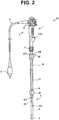
Fig. 2 is a diagram showing a state where an insertion section of an endoscope is covered by an overtube; -
Fig. 3 is a diagram describing configurations of a flexible tube portion and a rigidity changing mechanism portion; -
Fig. 4 is a diagram describing a positional relationship between the rigidity changing mechanism portion and the overtube; -
Fig. 5 is a diagram describing a positional relationship between the rigidity changing mechanism portion and the overtube; -
Fig. 6 is a diagram schematically showing a manner of change in rigidity of the insertion section of the endoscope system; -
FIG. 7 is a diagram schematically showing a manner of change in rigidity of the insertion section of the endoscope system; -
FIG. 8 is a diagram schematically showing a manner of change in rigidity of the insertion section of the endoscope system; -
FIG. 9 is a diagram schematically showing a manner of change in rigidity of the insertion section of the endoscope system; -
Fig. 10 is a diagram describing a first step of an insertion method using the endoscope system; -
Fig. 11 is a diagram describing a second step of the insertion method using the endoscope system; -
Fig. 12 is a diagram describing a third step of the insertion method using the endoscope system; -
Fig. 13 is a diagram describing a fourth step of the insertion method using the endoscope system; -
Fig. 14 is a diagram describing a fifth step of the insertion method using the endoscope system; -
Fig. 15 is a diagram describing a sixth step of the insertion method using the endoscope system; -
Fig. 16 is a diagram describing a seventh step of the insertion method using the endoscope system; and -
Fig. 17 is a diagram describing an eighth step of the insertion method using the endoscope system. - Hereinafter, a preferred mode of the present invention will be described with reference to the drawings. Note that, in each of the drawings used in the following description, the scale of display may be different for each structural component such that each structural component is large enough to be recognized in the drawing, and the present invention is not limited to the modes shown in the drawings with respect to the number of structural components, the shapes of the structural components, the proportion of the sizes of the structural components, and the relative positional relationship of respective structural components.
- An
endoscope system 50 of the present embodiment shown inFig. 1 includes anendoscope 1 and anovertube 40. Theendoscope 1 includes anelongated insertion section 2 which can be introduced into a subject such as a human body, and theinsertion section 2 has a configuration for observation of an inside of the subject. Note that the subject into which theinsertion section 2 of theendoscope 1 is introduced is not limited to a human body, but may be another living body. - The
endoscope 1 of the present embodiment is mainly configured of theinsertion section 2 which is formed in an elongated shape to be introduced into a subject, anoperation section 3 positioned at a proximal end of theinsertion section 2, and a universal cord 4 extending from theoperation section 3. - The
insertion section 2 is configured of adistal end portion 8 installed at a distal end, abendable bending portion 9 installed on a proximal end side of thedistal end portion 8, and aflexible tube portion 10 having flexibility and connecting a proximal end side of thebending portion 9 and a distal end side of theoperation section 3, where thedistal end portion 8, thebending portion 9, and theflexible tube portion 10 are provided in a linked manner. - A configuration and the like for observing an inside of a subject are installed in the
distal end portion 8. For example, an image pickup unit including an objective lens and an image pickup device and configured to optically observe the inside of the subject is installed in thedistal end portion 8. Furthermore, although not shown, thedistal end portion 8 is provided with an illumination light emitting unit configured to emit light configured to illuminate an object of the image pickup unit. Note that an ultrasound transducer for acoustically observing the inside of the subject by using ultrasound may be installed in thedistal end portion 8. - The
operation section 3 installed at the proximal end of theinsertion section 2 is provided with anangle operation knob 6 for bending thebending portion 9. Anendoscope connector 5 configured to be connectable to an external device, not shown, is provided at a proximal end portion of the universal cord 4. The external device to which theendoscope connector 5 is connected includes a camera control unit, and the like, configured to control the image pickup unit provided at thedistal end portion 8. - Furthermore, the
operation section 3 is provided with arigidity changing knob 21 for operating a rigidity changingmechanism portion 20 installed inside theflexible tube portion 10. The rigidity changingmechanism portion 20 is inserted in theflexible tube portion 10 along a longitudinal direction of theflexible tube portion 10, and is configured such that rigidity to flexion is changed according to an operation input by therigidity changing knob 21. That is, the rigidity changingmechanism portion 20 changes rigidity of theflexible tube portion 10 to flexion. - A configuration of the rigidity changing
mechanism portion 20 is well known, and detailed description is omitted, but as shown inFig. 3 , the rigidity changingmechanism portion 20 includes acoil pipe 22, afirst wire 24, asecond wire 25, and apulling mechanism portion 30. With respect to members configuring theinsertion section 2 and the rigidity changingmechanism portion 20, a direction toward thedistal end portion 8 side of theinsertion section 2 will be referred to as a distal end direction, and a direction toward theoperation section 3 side will be referred to as a proximal end direction. - The
coil pipe 22 is a linear member formed by helically winding a linear wire of metal, such as stainless alloy, around a predetermined axis A parallel to the longitudinal direction of theinsertion section 2, for example. Aproximal end 22b of thecoil pipe 22 is fixed to acoil fixing portion 23 provided inside theoperation section 3. - Furthermore, a
distal end 22a of thecoil pipe 22 is disposed, in theflexible tube portion 10, in the proximal end direction by a predetermined distance with respect to adistal end 10a of theflexible tube portion 10. That is, thecoil pipe 22 extends, inside theflexible tube portion 10, from theproximal end 10b of theflexible tube portion 10 and short of thedistal end 10a of theflexible tube portion 10. - The
first wire 24 is inserted through thecoil pipe 22. Adistal end 24a of thefirst wire 24 is fixed to thedistal end 22a of thecoil pipe 22, and aproximal end 24b of thefirst wire 24 is fixed to awire holding portion 30a of thepulling mechanism portion 30 described later. - For example, in the present embodiment, the
distal end 24a of thefirst wire 24 is fixed to a connectingportion 25 fixedly installed at thedistal end 22a of thecoil pipe 22. Note that thedistal end 24a of thefirst wire 24 may be directly fixed to thedistal end 22a of thecoil pipe 22. - A
distal end 26a of thesecond wire 26 is fixed to awire fixing portion 28 provided at aframe member 9a on a proximal end side of thebending portion 9, and aproximal end 26b of thesecond wire 26 is fixed to the connectingportion 25. Thesecond wire 26 restricts thedistal end 22a of thecoil pipe 22 from moving in the proximal end direction inside theflexible tube portion 10, and maintains a position of thecoil pipe 22 in the longitudinal direction in theflexible tube portion 10. - The
pulling mechanism portion 30 includes therigidity changing knob 21 which rotates relative to theoperation section 3, and thewire holding portion 30a which holds theproximal end 24b of thefirst wire 24 and which moves forward/backward in a direction along the axis A according to rotation of therigidity changing knob 21. - A
cam groove 21b is cut on an inner circumferential surface of therigidity changing knob 21. Thewire holding portion 30a is provided with acam pin 30b which slidably engages with thecam groove 21b. Due to the engagement between thecam groove 21b and thecam pin 30b, thewire holding portion 30a moves forward/backward in the direction along the axis A according to rotation of therigidity changing knob 21. The pullingmechanism portion 30 of the present embodiment configured in the above manner is capable of pulling thefirst wire 24 in the proximal end direction and changing tension applied to thefirst wire 24, according to a rotation operation of therigidity changing knob 21 by a user. - A compressive force is applied to the
coil pipe 22 according to the tension applied by the pullingmechanism portion 30 to thefirst wire 24. Resistance force of thecoil pipe 22 to bending deformation is increased by application of the compressive force. Accordingly, rigidity of theflexible tube portion 10 to flexion, in a range where thecoil pipe 22 is disposed inside, is changed according to the resistance force of thecoil pipe 22 to bending deformation. With the configuration described above, the rigidity changingmechanism portion 20 changes the rigidity at a part, of theflexible tube portion 10, where thecoil pipe 22 is inserted. - In the present embodiment, a length from the
proximal end 10b of theflexible tube portion 10 to the distal end L1 of thecoil pipe 22 in a state where theflexible tube portion 10 is linearly held is L1. Accordingly, a range, of theinsertion section 2 of theendoscope 1 of the present embodiment, over the length L1 from theproximal end 10b of theflexible tube portion 10 in the distal end direction along the longitudinal direction is arigidity change region 2a where rigidity can be changed by the rigidity changingmechanism portion 20. - The
overtube 40 includes a flexiblecylindrical portion 41 having a cylindrical shape. Thecylindrical portion 41 has a cylindrical shape which is open on both ends, and as shown inFig. 2 , allows insertion of theinsertion section 2 of theendoscope 1. In other words, thecylindrical portion 41 may cover an outer circumference of theinsertion section 2. In a state where theinsertion section 2 is inserted inside, thecylindrical portion 41 flexes according to deformation of theinsertion section 2. Furthermore, thecylindrical portion 41 is capable of sliding relative to theinsertion section 2, along the longitudinal direction of theinsertion section 2. -
Fig. 2 shows a state where thecylindrical portion 41 is disposed in a most proximal end direction of theinsertion section 2. That is,Fig. 2 shows a state where theinsertion section 2 of theendoscope 1 is pushed deepest into theovertube 40. - As shown in
Figs. 1 and2 , a length L2 of thecylindrical portion 41 in an axial direction (longitudinal direction) is shorter than the length L1 of therigidity change region 2a. - Accordingly, as shown in
Fig. 2 , in the case where thecylindrical portion 41 is disposed in the most proximal end direction of theinsertion section 2, a distal end portion of therigidity change region 2a provided at theflexible tube portion 10 protrudes in the distal end direction from adistal end portion 41a of thecylindrical portion 41 of theovertube 40. In other words, in the case where theinsertion section 2 is pushed deepest into thecylindrical portion 41 of theovertube 40, the distal end portion of therigidity change region 2a is exposed from thecylindrical portion 41 in the distal end direction. - A
balloon 42, which is an expandable member, is installed at thedistal end portion 41a of thecylindrical portion 41. Furthermore, aballoon air port 43 communicating with an inside of theballoon 42 via a pipe, not shown, is installed at aproximal end portion 41b of thecylindrical portion 41. Theballoon 42 has a doughnut shape which is disposed to surround an outer circumference of thedistal end portion 41a of thecylindrical portion 41. Theballoon 42 expands or contracts according to inflow or outflow of air through theballoon air port 43. - As described above, with the
endoscope system 50 of the present embodiment, the total length L2 of thecylindrical portion 41 of theovertube 40 covering theinsertion section 2 is shorter than the length L1 of therigidity change region 2a of theinsertion section 2. Accordingly, with theendoscope system 50 of the present embodiment, by changing relative positions of theovertube 40 and theinsertion section 2 in the longitudinal direction in a state where theinsertion section 2 is covered by theovertube 40, selection between a state where the distal end portion of therigidity change region 2a is exposed from theovertube 40 in the distal end direction and a state where the distal end portion of therigidity change region 2a is covered by theovertube 40 is enabled. - For example, as shown in
Fig. 4 , when theinsertion section 2 is relatively pushed in the distal end direction with respect to theovertube 40, the distal end portion of therigidity change region 2a is exposed from theovertube 40 in the distal end direction. Moreover, for example, as shown inFig. 5 , when theinsertion section 2 is relatively pulled back in the proximal end direction with respect to theovertube 40, the distal end portion of therigidity change region 2a is covered by theovertube 40. -
Figs. 6, 7, 8, and 9 show manners of change in rigidity of theinsertion section 2 and theovertube 40 in the longitudinal direction. In schematic graphs shown inFigs. 6, 7, 8, and 9 , an x-axis, which is a horizontal axis, indicates a distance in the longitudinal direction from the distal end of theinsertion section 2, and a y-axis, which is a vertical axis, indicates rigidity to deformation in a bending direction of theinsertion section 2 and theovertube 40. - With respect to the x-axis, x = 0 is the distal end of the
insertion section 2, and x = L0 is the proximal end of the insertion section 2 (i.e., theproximal end 10b of the flexible tube portion 10). With respect to the y-axis, rigidity is increased toward an upper side in the drawing. A one-dot chain line in the drawing indicates the rigidity of theinsertion section 2, and a two-dot chain line indicates the rigidity of theovertube 40. A value obtained by adding the rigidity of theinsertion section 2 and the rigidity of theovertube 40 at an x-coordinate indicates the rigidity of theinsertion section 2 of theendoscope system 50 at the x-coordinate. -
Fig. 6 shows a state where the distal end portion of therigidity change region 2a is exposed from theovertube 40 in the distal end direction, and where an increase operation of the rigidity of theflexible tube portion 10 by the rigidity changingmechanism portion 20 is not performed. That is, in the state shown inFig. 6 , a value at an x-coordinate xC of the distal end of theovertube 40 is greater than L0 - L1. - As shown in
Fig. 6 , in a region (x ≥ xC) covered by theovertube 40, rigidity St of thecylindrical portion 41 of theovertube 40 is combined with the rigidity of theinsertion section 2, and thus, the rigidity is increased. - Note that, in
Fig. 6 , for the sake of description, the rigidity of theinsertion section 2 of the endoscope is indicated to take a constant value 11 regardless of the x-coordinate, but the rigidity of theinsertion section 2 may change according to a change in the x-coordinate. The same thing can be said forFigs. 7, 8, and 9 . -
Fig. 7 shows a state where the distal end portion of therigidity change region 2a is exposed from theovertube 40 in the distal end direction, and where the increase operation of the rigidity of theflexible tube portion 10 by the rigidity changingmechanism portion 20 is performed. - In the state shown in
Fig. 7 , the rigidity of therigidity change region 2a of theinsertion section 2 is increased. Therigidity change region 2a is a region where the x-coordinate is greater than L0 - L1. In the state shown inFig. 7 , the distal end of theovertube 40 is positioned inside therigidity change region 2a. - That is, a region where the rigidity is increased by being covered with the
overtube 40 is positioned on the proximal end side with respect to the distal end of therigidity change region 2a. Accordingly, in the state shown inFig. 7 , rigidity is lowest in a first region (x < (L0 - L1)) which is on the distal end side with respect to therigidity change region 2a, middle in a second region ((L0 - L1) ≤ x < xC), of therigidity change region 2a, which is exposed from theovertube 40 in the distal end direction, and highest in a third region (x ≥ xC), of therigidity change region 2a, which is covered by theovertube 40. - The first region, the second region, and the third region where the rigidity is gradually increased in such an order are disposed in order from the distal end of the
insertion section 2 toward the proximal end direction. Accordingly, in the state shown inFig. 7 , the rigidity is slowly increased from the distal end of theinsertion section 2 toward the proximal end direction. When inclination of the change in the rigidity from the distal end of theinsertion section 2 toward the proximal end direction is gradual, insertability at the time of insertion of theinsertion section 2 into a subject is increased. -
Fig. 8 shows a state where the distal end portion of therigidity change region 2a is covered by theovertube 40, and where the increase operation of the rigidity of theflexible tube portion 10 by the rigidity changingmechanism portion 20 is not performed. That is, in the state shown inFig. 7 , the value at the x-coordinate xC of the distal end of theovertube 40 is smaller than L0 - L1. -
Fig. 9 shows a state where the distal end portion of therigidity change region 2a is covered by theovertube 40, and where the increase operation of the rigidity of theflexible tube portion 10 by the rigidity changingmechanism portion 20 is performed. - In the present embodiment, an increase width St of the rigidity due to covering with the
overtube 40 is set to be equal to an increase width of the rigidity of theflexible tube portion 10 achieved by the rigidity changingmechanism portion 20. Accordingly, in the present embodiment, when the distal end of theovertube 40 is positioned on the distal end side with respect to therigidity change region 2a, the rigidity of theflexible tube portion 10 may be increased without performing the rigidity increase operation by the rigidity changingmechanism portion 20, as shown inFig. 8 . - Next, a method of inserting the
insertion section 2 of theendoscope 1 into alarge intestine 60 of a human body, which is a subject, through ananus 61 by using theendoscope system 50 of the present embodiment will be described with reference toFigs. 10 to 17 . - First, as shown in
Fig. 10 , in a first step, only theinsertion section 2 of theendoscope 1 is inserted from theanus 61 until the distal end reaches asigmoid colon 60a of thelarge intestine 60, in a state where the increase operation of the rigidity of theflexible tube portion 10 by the rigidity changingmechanism portion 20 is not performed. Here, theinsertion section 2 is covered by the overtube 40while being in a state where theovertube 40 is drawn toward theproximal end 10b side of the flexible tube portion 10 (i.e., theoperation section 3 side). That is, theovertube 40 is positioned outside theanus 61. - In the first step, the range, of the
insertion section 2, which is inserted in thelarge intestine 60 is not covered by theovertube 40, and the increase operation of the rigidity of theflexible tube portion 10 by the rigidity changingmechanism portion 20 is not performed, and thus, the rigidity is the lowest and theinsertion section 2 is soft. Accordingly, theinsertion section 2 may be easily moved forward inside thesigmoid colon 60a with many flexions. - Next, as shown in
Fig. 11 , in a second step, theovertube 40 is moved in the distal end direction along theinsertion section 2 so that the distal end of theovertube 40 reaches thesigmoid colon 60a. Here, theovertube 40 is positioned on the distal end side with respect to the distal end of the rigidity changingmechanism portion 20. Due to such an operation, the rigidity of theinsertion section 2 covered by theovertube 40 is increased, as shown inFig. 8 . - Then, air is sent into the
balloon 42 from theballoon air port 43 to expand theballoon 42, and a position of theovertube 40 is fixed. - Next, as shown in
Fig. 12 , in a third step, thesigmoid colon 60a is straightened by pulling theovertube 40, the position of which is fixed, and theinsertion section 2 with increased rigidity. Moreover, the increase operation of the rigidity of theflexible tube portion 10 by the rigidity changingmechanism portion 20 is performed. - Next, as shown in
Fig. 13 , in a fourth step, theinsertion section 2 on which the rigidity increase operation is performed is pushed in while the position of theovertube 40 is maintained fixed, and the distal end of theinsertion section 2 is moved forward to asplenic flexure 60d between a descendingcolon 60b and atransverse colon 60c. Here, as shown inFig. 7 , the rigidity of theinsertion section 2 is gradually increased from the distal end in the proximal end direction. That is, the distal end side of theinsertion section 2 where the rigidity is low may be easily moved forward, while maintaining the rigidity of a part, of theinsertion section 2, on the proximal end side which is inserted in the straightenedsigmoid colon 60a. - Then, as shown in
Fig. 14 , in a fifth step, the distal end of theinsertion section 2 is moved forward into thetransverse colon 60c. - Next, as shown in
Fig. 15 , in a sixth step, after theballoon 42 is contracted, theovertube 40 is moved in the distal end direction along theinsertion section 2, and the distal end of theovertube 40 is moved forward to thesplenic flexure 60d. Then, a state is reached where the increase operation of the rigidity of theflexible tube portion 10 by the rigidity changingmechanism portion 20 is not performed. - At this time, as shown in
Fig. 8 , the rigidity of theflexible tube portion 10 is increased due to the presence of theovertube 40, even if the rigidity increase operation by the rigidity changingmechanism portion 20 is not performed. Accordingly, the shape of the straightenedsigmoid colon 60a is maintained. - Next, as shown in
Fig. 16 , in a seventh step, in a state where the increase operation of the rigidity of theflexible tube portion 10 by the rigidity changingmechanism portion 20 is not performed, the position of theovertube 40 is fixed, and only theinsertion section 2 is moved forward until the distal end reaches ahepatic flexure 60e. Here, the shape of thesigmoid colon 60a which is straightened due to the rigidity of theovertube 40 is maintained, and also, a range, of theinsertion section 2, which is inserted in thelarge intestine 60c is soft and the rigidity is the lowest because the increase operation of the rigidity of theflexible tube portion 10 by the rigidity changingmechanism portion 20 is not performed and the range is not covered by theovertube 40, and thus, theinsertion section 2 may be easily moved forward in thetransverse colon 60c with many flexions and which is not fixed (in a rigid state, insertion is difficult because a flexed portion of the transverse colon greatly hangs down toward the anus). - Next, as shown in
Fig. 17 , in an eighth step, the increase operation of the rigidity of theflexible tube portion 10 by the rigidity changingmechanism portion 20 is performed, and thetransverse colon 60c is lifted up. Then, theovertube 40 is moved in the distal end direction along theinsertion section 2, and the distal end of theovertube 40 is moved forward to thehepatic flexure 60e, and theballoon 42 is expanded to fix the position of theovertube 40. - When the distal end of the
overtube 40 is fixed near thehepatic flexure 60e, shapes of the straightenedsigmoid colon 60a and the liftedtransverse colon 60c are maintained, and thus, an operation of moving theinsertion section 2 forward to an ascendingcolon 60f, which is located even deeper in the large intestine, is facilitated. - As described above, the
endoscope system 50 of the present embodiment enables an insertion operation of theinsertion section 2 into a subject to be easily performed, by allowing setting of various levels of rigidity (i.e., by increasing the degree of freedom regarding setting of rigidity in the longitudinal direction) by combining switching between performance and non-performance of the increase operation of rigidity of theflexible tube portion 10 by the rigidity changingmechanism portion 20, and forward/backward movement of theovertube 40 in the longitudinal direction relative to theinsertion section 2. - The present invention is not limited to the embodiment described above, and changes may be made as appropriate without departing from the essence or idea of the invention that can be read from the claims and the entire specification. An endoscope system involving such changes is also included within the technical scope of the present invention.
- The present application claims priority from Japanese Patent Application No.
2015-227903
Claims (3)
- An endoscope system comprising:an endoscope includingan insertion section formed in an elongated shape,a flexible tube portion provided at a proximal end side of the insertion section, anda rigidity changing mechanism portion provided inside the flexible tube portion, and configured to change rigidity of the flexible tube portion by an operation performed on a hand side; anda flexible overtube formed in a cylindrical shape extending in an axial direction, into which the insertion section is inserted, whereina rigidity change region of the flexible tube portion by the rigidity changing mechanism portion is set to be from an intermediate portion to a proximal end portion of the flexible tube portion, and a total length of the overtube in the axial direction is set to be shorter than a total length of the rigidity change region.
- The endoscope system according to claim 1, wherein an expandable balloon is disposed on an outer circumference of a distal end of the overtube.
- The endoscope system according to claim 1, wherein the insertion section is slidable in the axial direction in a state where the insertion section is inserted in the overtube.
Applications Claiming Priority (2)
| Application Number | Priority Date | Filing Date | Title |
|---|---|---|---|
| JP2015227903 | 2015-11-20 | ||
| PCT/JP2016/083818 WO2017086312A1 (en) | 2015-11-20 | 2016-11-15 | Endoscope system |
Publications (2)
| Publication Number | Publication Date |
|---|---|
| EP3363344A1 true EP3363344A1 (en) | 2018-08-22 |
| EP3363344A4 EP3363344A4 (en) | 2019-10-09 |
Family
ID=58718929
Family Applications (1)
| Application Number | Title | Priority Date | Filing Date |
|---|---|---|---|
| EP16866313.6A Withdrawn EP3363344A4 (en) | 2015-11-20 | 2016-11-15 | Endoscope system |
Country Status (5)
| Country | Link |
|---|---|
| US (1) | US10888214B2 (en) |
| EP (1) | EP3363344A4 (en) |
| JP (1) | JP6423539B2 (en) |
| CN (1) | CN108366710B (en) |
| WO (1) | WO2017086312A1 (en) |
Families Citing this family (9)
| Publication number | Priority date | Publication date | Assignee | Title |
|---|---|---|---|---|
| CN108495582B (en) | 2015-09-03 | 2020-10-02 | 海王星医疗公司 | Instrument for advancing an endoscope through the small intestine |
| WO2018035452A1 (en) | 2016-08-18 | 2018-02-22 | Neptune Medical | Device and method for enhanced visualization of the small intestine |
| US10939814B2 (en) * | 2016-08-19 | 2021-03-09 | Jason Andrew Slate | Systems and method for preventing air escape and maintaining air distension |
| CN111479493B (en) * | 2017-12-28 | 2023-04-25 | 奥林巴斯株式会社 | Endoscope and endoscope system |
| JP2021531111A (en) | 2018-07-19 | 2021-11-18 | ネプチューン メディカル インク. | Dynamic hardening medical composite structure |
| US11793392B2 (en) | 2019-04-17 | 2023-10-24 | Neptune Medical Inc. | External working channels |
| WO2021059935A1 (en) * | 2019-09-26 | 2021-04-01 | テルモ株式会社 | Catheter |
| EP4126095A4 (en) | 2020-03-30 | 2024-04-24 | Neptune Medical Inc | Layered walls for rigidizing devices |
| US20230346204A1 (en) | 2022-04-27 | 2023-11-02 | Neptune Medical Inc. | Endoscope sheath apparatuses |
Family Cites Families (20)
| Publication number | Priority date | Publication date | Assignee | Title |
|---|---|---|---|---|
| JPH07213481A (en) * | 1994-02-01 | 1995-08-15 | Fuji Photo Optical Co Ltd | Soft endoscope |
| JP3660775B2 (en) * | 1997-02-26 | 2005-06-15 | ペンタックス株式会社 | Endoscope insertion assisting tool clasp |
| US5993379A (en) | 1996-02-25 | 1999-11-30 | Asahi Kogaku Kogyo Kabushiki Kaisha | Fluid splashing preventive device |
| JP3776557B2 (en) | 1997-04-10 | 2006-05-17 | オリンパス株式会社 | Endoscope |
| US6293908B1 (en) | 1999-02-12 | 2001-09-25 | Fuji Photo Optical Co., Ltd. | Mouthpiece and insertion assisting device for endoscope |
| JP3596661B2 (en) * | 1999-02-22 | 2004-12-02 | 富士写真光機株式会社 | Endoscope insertion aid |
| JP3620574B2 (en) * | 1999-02-22 | 2005-02-16 | フジノン株式会社 | Endoscope mouthpiece |
| US7128708B2 (en) * | 2002-06-13 | 2006-10-31 | Usgi Medical Inc. | Shape lockable apparatus and method for advancing an instrument through unsupported anatomy |
| WO2001023022A1 (en) * | 1999-09-24 | 2001-04-05 | Omnisonics Medical Technologies, Inc. | Variable stiffness medical device |
| WO2003073921A1 (en) * | 2002-03-06 | 2003-09-12 | Atropos Limited | A steerable colonoscope probe with variable stiffness |
| JP4091016B2 (en) * | 2004-04-22 | 2008-05-28 | オリンパス株式会社 | Endoscope system |
| JP4499479B2 (en) * | 2004-05-28 | 2010-07-07 | オリンパス株式会社 | Endoscope overtube and small intestine endoscope system |
| JP2006014960A (en) * | 2004-07-01 | 2006-01-19 | Olympus Corp | Endoscope |
| WO2006028019A1 (en) * | 2004-09-07 | 2006-03-16 | Olympus Corporation | Endoscope |
| EP2394565B1 (en) * | 2009-08-07 | 2013-05-01 | Olympus Medical Systems Corp. | Medical system |
| JP5591043B2 (en) * | 2010-09-22 | 2014-09-17 | 富士フイルム株式会社 | Endoscope and its flexible part |
| JP5124629B2 (en) * | 2010-10-08 | 2013-01-23 | 富士フイルム株式会社 | Endoscope and hardness adjustment device |
| JP6368256B2 (en) * | 2015-02-05 | 2018-08-01 | 富士フイルム株式会社 | Endoscope system |
| US11553832B2 (en) * | 2015-06-05 | 2023-01-17 | Fujifilm Corporation | Endoscope system |
| JP6444809B2 (en) * | 2015-06-05 | 2018-12-26 | 富士フイルム株式会社 | Endoscope system |
-
2016
- 2016-11-15 JP JP2017536053A patent/JP6423539B2/en active Active
- 2016-11-15 EP EP16866313.6A patent/EP3363344A4/en not_active Withdrawn
- 2016-11-15 WO PCT/JP2016/083818 patent/WO2017086312A1/en active Application Filing
- 2016-11-15 CN CN201680067277.3A patent/CN108366710B/en active Active
-
2018
- 2018-05-18 US US15/983,201 patent/US10888214B2/en active Active
Also Published As
| Publication number | Publication date |
|---|---|
| CN108366710A (en) | 2018-08-03 |
| US20180263469A1 (en) | 2018-09-20 |
| WO2017086312A1 (en) | 2017-05-26 |
| JPWO2017086312A1 (en) | 2017-11-24 |
| EP3363344A4 (en) | 2019-10-09 |
| CN108366710B (en) | 2020-08-11 |
| US10888214B2 (en) | 2021-01-12 |
| JP6423539B2 (en) | 2018-11-14 |
Similar Documents
| Publication | Publication Date | Title |
|---|---|---|
| US10888214B2 (en) | Endoscope system including overtube and endoscope having rigidity changing mechanism | |
| US20160287054A1 (en) | Endoscope | |
| JP4637903B2 (en) | Endoscope system | |
| US11006820B2 (en) | Flexible tube insertion apparatus | |
| EP2457491B1 (en) | Endoscope | |
| EP1849396A1 (en) | Flexible tube for endoscope, and endoscope device | |
| US20200323421A1 (en) | Endoscope and endoscope system | |
| EP3087898A1 (en) | Endoscope | |
| US10485410B2 (en) | Flexible tube insertion apparatus | |
| EP3795060A1 (en) | Endoscope | |
| US20160249900A1 (en) | Elastic tube, control device, and medical equipment | |
| EP3269292A1 (en) | Endoscope | |
| WO2018216142A1 (en) | Flexible tube insertion device and insertion control device | |
| JPWO2015019753A1 (en) | Medical instruments | |
| JP2007054400A (en) | Endoscope | |
| EP4316347A1 (en) | Endoscope having tension adjustment part | |
| EP4316346A1 (en) | Endoscope having friction control part | |
| JP5391006B2 (en) | Endoscope insertion aid | |
| CN108348135B (en) | Endoscope system | |
| WO2017109987A1 (en) | Flexible tube insertion apparatus | |
| CN112423642A (en) | Endoscope with a detachable handle | |
| CN117122257A (en) | Endoscopic instrument tube, distal expandable insertion portion, handle, and endoscope | |
| JPH0445177B2 (en) | ||
| JP2012125512A (en) | Endoscope holding device and endoscope system |
Legal Events
| Date | Code | Title | Description |
|---|---|---|---|
| STAA | Information on the status of an ep patent application or granted ep patent |
Free format text: STATUS: THE INTERNATIONAL PUBLICATION HAS BEEN MADE |
|
| PUAI | Public reference made under article 153(3) epc to a published international application that has entered the european phase |
Free format text: ORIGINAL CODE: 0009012 |
|
| STAA | Information on the status of an ep patent application or granted ep patent |
Free format text: STATUS: REQUEST FOR EXAMINATION WAS MADE |
|
| 17P | Request for examination filed |
Effective date: 20180518 |
|
| AK | Designated contracting states |
Kind code of ref document: A1 Designated state(s): AL AT BE BG CH CY CZ DE DK EE ES FI FR GB GR HR HU IE IS IT LI LT LU LV MC MK MT NL NO PL PT RO RS SE SI SK SM TR |
|
| AX | Request for extension of the european patent |
Extension state: BA ME |
|
| DAV | Request for validation of the european patent (deleted) | ||
| DAX | Request for extension of the european patent (deleted) | ||
| A4 | Supplementary search report drawn up and despatched |
Effective date: 20190911 |
|
| RIC1 | Information provided on ipc code assigned before grant |
Ipc: A61M 25/01 20060101ALI20190905BHEP Ipc: G02B 23/24 20060101ALI20190905BHEP Ipc: A61M 25/00 20060101ALI20190905BHEP Ipc: A61B 1/00 20060101AFI20190905BHEP Ipc: A61M 25/06 20060101ALI20190905BHEP |
|
| STAA | Information on the status of an ep patent application or granted ep patent |
Free format text: STATUS: THE APPLICATION IS DEEMED TO BE WITHDRAWN |
|
| 18D | Application deemed to be withdrawn |
Effective date: 20200603 |