EP3363280A1 - Antriebssystem für einen erntevorsatz einer erntemaschine mit hydraulischer leistungsübertragung - Google Patents
Antriebssystem für einen erntevorsatz einer erntemaschine mit hydraulischer leistungsübertragung Download PDFInfo
- Publication number
- EP3363280A1 EP3363280A1 EP18152946.2A EP18152946A EP3363280A1 EP 3363280 A1 EP3363280 A1 EP 3363280A1 EP 18152946 A EP18152946 A EP 18152946A EP 3363280 A1 EP3363280 A1 EP 3363280A1
- Authority
- EP
- European Patent Office
- Prior art keywords
- header
- hydraulic
- hydraulic motor
- motor
- harvesting
- Prior art date
- Legal status (The legal status is an assumption and is not a legal conclusion. Google has not performed a legal analysis and makes no representation as to the accuracy of the status listed.)
- Granted
Links
Images

Classifications
-
- A—HUMAN NECESSITIES
- A01—AGRICULTURE; FORESTRY; ANIMAL HUSBANDRY; HUNTING; TRAPPING; FISHING
- A01D—HARVESTING; MOWING
- A01D41/00—Combines, i.e. harvesters or mowers combined with threshing devices
- A01D41/12—Details of combines
- A01D41/14—Mowing tables
- A01D41/142—Header drives
-
- A—HUMAN NECESSITIES
- A01—AGRICULTURE; FORESTRY; ANIMAL HUSBANDRY; HUNTING; TRAPPING; FISHING
- A01B—SOIL WORKING IN AGRICULTURE OR FORESTRY; PARTS, DETAILS, OR ACCESSORIES OF AGRICULTURAL MACHINES OR IMPLEMENTS, IN GENERAL
- A01B59/00—Devices specially adapted for connection between animals or tractors and agricultural machines or implements
- A01B59/06—Devices specially adapted for connection between animals or tractors and agricultural machines or implements for machines mounted on tractors
- A01B59/064—Devices specially adapted for connection between animals or tractors and agricultural machines or implements for machines mounted on tractors for connection to the front of the tractor
-
- A—HUMAN NECESSITIES
- A01—AGRICULTURE; FORESTRY; ANIMAL HUSBANDRY; HUNTING; TRAPPING; FISHING
- A01D—HARVESTING; MOWING
- A01D41/00—Combines, i.e. harvesters or mowers combined with threshing devices
- A01D41/12—Details of combines
- A01D41/127—Control or measuring arrangements specially adapted for combines
- A01D41/1274—Control or measuring arrangements specially adapted for combines for drives
-
- A—HUMAN NECESSITIES
- A01—AGRICULTURE; FORESTRY; ANIMAL HUSBANDRY; HUNTING; TRAPPING; FISHING
- A01D—HARVESTING; MOWING
- A01D69/00—Driving mechanisms or parts thereof for harvesters or mowers
- A01D69/03—Driving mechanisms or parts thereof for harvesters or mowers fluid
-
- A—HUMAN NECESSITIES
- A01—AGRICULTURE; FORESTRY; ANIMAL HUSBANDRY; HUNTING; TRAPPING; FISHING
- A01D—HARVESTING; MOWING
- A01D89/00—Pick-ups for loaders, chaff-cutters, balers, field-threshers, or the like, i.e. attachments for picking-up hay or the like field crops
- A01D89/005—Drives
-
- A—HUMAN NECESSITIES
- A01—AGRICULTURE; FORESTRY; ANIMAL HUSBANDRY; HUNTING; TRAPPING; FISHING
- A01F—PROCESSING OF HARVESTED PRODUCE; HAY OR STRAW PRESSES; DEVICES FOR STORING AGRICULTURAL OR HORTICULTURAL PRODUCE
- A01F29/00—Cutting apparatus specially adapted for cutting hay, straw or the like
- A01F29/09—Details
- A01F29/14—Drives
Definitions
- the invention relates to a drive system for a harvesting attachment of a harvesting machine, comprising a drive motor and a drive train connected between the drive motor and one or more driven elements of the header with an adjustable hydraulic pump arranged on board the harvesting machine and a hydraulic motor connected in a closed circuit to the hydraulic pump , and a corresponding harvester with a header.
- Self-propelled harvesters are usually equipped with demountable harvesting attachments, which are removed for road transport from a feeder channel attached to the front of the harvester and, if necessary, exchanged for another harvesting header for harvesting another crop.
- the drive of the header is usually done by the harvester and can provide a purely mechanical drive train between the drive motor of the harvester and the header, or the header is driven by a hydraulic motor, which is acted upon by a powered by the drive motor of the harvester hydraulic pump with pressurized hydraulic fluid becomes.
- the post-published DE 10 2017 200 330 A1 Although describes a header drive in a closed hydraulic circuit with a on board the header hydraulic motor, but does not mention a detachable hydraulic coupling connection between header and harvester.
- a closed hydraulic circuit for driving the header has the advantage that the transmissible drive power can be greater than in an open hydraulic circuit. So far, such closed hydraulic circuits were always provided completely on board the harvester and transferred the drive power of the hydraulic motor by a separable mechanical drive train on the header, or mechanically transferred to the header drive power is transmitted through a arranged exclusively on board the harvesting header, closed hydraulic circuit. Although there was also the transfer of hydraulic power from the harvester to the header, but only in an open hydraulic circuit that can only transmit limited power.
- the object underlying the invention is seen to provide a drive system for a header of a harvester and a corresponding harvester with a header which does not require a mechanical drive connection between the harvester and the header, but nevertheless a transmission of a sufficiently large drive power allows.
- a drive system for a harvesting header of a harvesting machine comprises a drive motor and a drive train connected between the drive motor and one or more driven elements of the header having an adjustable hydraulic pump mounted on the harvester and a hydraulic motor connected in a closed loop to the hydraulic pump at the header attached and is connected by releasable hydraulic coupling connections with the hydraulic pump.
- the line leading from the hydraulic pump to the hydraulic motor may include a first coupling connection and the line returning from the hydraulic motor to the hydraulic pump may include a second coupling connection, the first and second coupling connections being respectively mounted to a common holder on the harvesting attachment side and the harvesting machine side.
- the header can be provided with a readable by the harvester label that can be fed to a control device, which is recognizable in the case of the information associated with one of the label that the header contains a hydraulic motor for driving the header, is operable between the Open hydraulic pump and the hydraulic motor arranged valve.
- a harvesting machine-side hydraulic motor can continue to be present, with which a harvesting attachment not equipped with a hydraulic motor can be driven.
- the control device may be operable to transfer a valve arranged between the hydraulic pump and the hydraulic motor into a position connecting the harvesting machine-side hydraulic motor with the hydraulic pump or commanding the engine-side hydraulic motor designed as an adjusting motor to a neutral position, if the header is not provided with an identification , which indicates that the header is equipped with a hydraulic motor.
- the identification may also contain further operating data of the header, such as maximum drive torque or appropriate speeds, which can be read out and taken into account by the control device.
- the harvest engine side hydraulic motor and the valve can be omitted. Then all harvesting attachments to be used with the harvester would be equipped with a hydraulic motor.
- the harvesting machine side coupling connections can be separated from the hydraulic pump by the valve in its position connecting the harvesting machine side hydraulic motor with the hydraulic pump.
- the header can be a picker with a cross auger and a tine rotor.
- the drive of the cross auger can be done by the hydraulic motor.
- the hydraulic motor can be arranged within the transverse screw conveyor and / or designed as a radial piston motor.
- the drive of the tine rotor can be effected via a hydrostatic transmission which can be driven by the transverse screw conveyor.
- FIG. 1 a harvester 10 is shown in the manner of a self-propelled forage harvester in a schematic side view.
- the harvester 10 is built on a frame 12 supported by front driven wheels 14 and steerable rear wheels 16.
- the operation of the harvesting machine 10 is carried out by a driver's cab 18, from which a header 20 is visible.
- the harvester 20 operatively separable from the harvesting machine 10 is designed as a pick-up in the illustrated embodiment and comprises a transverse screw conveyor 74, a zinc rotor 84 arranged in front of it and support wheels 88 and a downholder 92 above the zinc rotor 84.
- a feed conveyor 22 with Vorpresswalzen which are arranged within a feed housing 24 on the front side of the forage harvester 10, arranged below the driver's cab 18 chopper 26 in the form of a chopper drum, which chops it into small pieces and it Releases conveyor 28.
- the crop leaves the harvesting machine 10 to a transporting vehicle traveling alongside, via a discharge shaft 30 that is rotatable about an approximately vertical axis and can be tilted.
- directional details such as laterally, downwardly and upwardly, refer to the forward direction V of the harvesting machine 10, which in FIG of the FIG. 1 goes to the right.
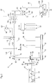
- FIG. 2 shows a plan view of the drive assembly of the harvester 10 and the Harvesting header 20.
- an internal combustion engine serving as a drive motor 32, in particular in the form of a diesel engine, which is connected to longitudinal members and / or cross members of the frame 12.
- the engine 32 extends in the forward direction of the harvester 10 to about the rear end of the frame 12 and includes a crankshaft 34 that extends forward out of the housing of the engine 32.
- the crankshaft 34 drives a horizontally and forwardly extending output shaft 36.
- the output shaft 36 is connected at its front end with an angle gear 38, which is composed of a first bevel gear 40, which is connected via a coupling 42 with the longitudinal shaft 36, and a second bevel gear 44, which meshes with the first bevel gear 40.
- the axis of rotation of the second bevel gear 44 extends horizontally and transversely to the forward direction.
- the second bevel gear 44 is connected to a shaft 46 which drives a pulley 48.
- the pulley 48 is wrapped by a drive belt 50, which also wraps around a pulley 52 for driving the conveyor 28 and a pulley 54 for driving the chopper 26.
- the angle gear 38, the shaft 46, the pulleys 48 and 54 and the drive belt 50 form a drive train connecting the output shaft 36 with the chopper 26.
- the longitudinal shaft 36 carries between the clutch 42 and the housing of the engine 32 in addition a circumferentially toothed gear 56 which meshes with another gear 58, which drives a pump unit 62 via a shaft 60, which is to supply the hydraulic motors for driving the wheels fourteenth , 16, a via a transmission 64 for driving the intake conveyor 22 serving hydraulic motor 78 and other hydraulically driven components of the harvester 10 is used.
- the shaft 46 is in the illustrated embodiment permanently in drive connection with a hydraulic pump 66 with adjustable displacement and flow direction.
- the hydraulic pump 66 is hydraulically fluidically connected in a closed circuit to a hydraulic motor 68, which has a fixed displacement and is used to drive the driven elements of the header 20, which could also be a header for maize harvesting or production of whole plant silage.
- the hydraulic motor 68 (or several hydraulic motors 68) would be used to drive mowing equipment and Serve subsidies for the crop.
- An outlet 82 of the hydraulic pump 66 and an inlet 86 of the hydraulic motor 68 are interconnected by a first pressure line 120.
- An inlet 80 of the hydraulic pump 66 and an outlet 72 of the hydraulic motor 68 are interconnected by a second pressure line 122.
- the hydraulic motor 68 and the hydraulic pump 66 are operated in a closed circuit, which allows the transmission of sufficiently large pressure and sufficient flow rate of the hydraulic fluid and thus a sufficient drive power to drive the movable elements of the header 20.
- the hydraulic motor 68 is located on board the header 20.
- detachable coupling connections in the pressure lines 120, 122 are provided, each having a clutch 104 and 108 by the harvester 10 and a Plug 106 and 110 on the part of the header 20 include.
- the plugs 106, 110 are combined in a holder 100 on the header side.
- the couplings 104, 108 are summarized erntemaschinen mon spirit in a holder 102.
- the holders 100, 102 can be used in particular as a so-called multi-coupler (s. EP 1 346 625 A1 ) and allow both pressure lines 120 and 122 to be disconnected or connected simultaneously.
- a leakage oil line (not shown) can be guided via the holders 100, 102.
- a storage device 90 is provided, which is connected via a line 124 to a control device 70.
- the line 124 includes a plug 112 and a coupling 114, which are also respectively integrated into the holder 100 or 102 and connected or disconnected therewith.
- the hydraulic motor 68 serves to drive the transverse screw conveyor 74.
- the hydraulic motor 68 can be designed as a radial piston motor. Such radial piston motors allow speeds that are suitable for driving the cross auger 74 without the interposition of a transmission gear.
- the output shaft 126 of the hydraulic motor 68 is therefore directly connected via a flange 128 to the inner wall of the hollow interior of the cross auger 74.
- the hydraulic motor 68 is disposed within the hollow interior of the cross auger 74 in the illustrated embodiment, but could be mounted outside the hollow interior.
- transverse screw conveyor 74 it would also be conceivable to drive the transverse screw conveyor 74 by means of an axial piston motor and, if required, to provide a gearbox for speed change (in particular reduction) between the axial piston motor and the transverse screw conveyor 74.
- the axial piston motor and possibly the transmission can be mounted in the hollow interior of the transverse auger 74.
- the drive of the tine rotor 84 via a arranged on board the harvesting attachment 20, hydrostatic transmission with a second hydraulic pump 130 and a second hydraulic motor 132.
- the drive shaft of the second hydraulic pump 130 is coupled to the cross auger 74.
- the output shaft 138 of the second hydraulic motor 132 is coupled to the tine rotor 84.
- the second hydraulic pump 130 and / or the second hydraulic motor 132 could also be located within the hollow interior of the cross auger 74 and the tine rotor 84, respectively.
- the second hydraulic pump 130 is connected to the second hydraulic motor 132 in a closed circuit.
- the delivery volume of the second hydraulic pump 130 can be adjusted by means of an actuator which can be connected to the control device 70 via a further line (not shown) guided via the holders 100 and 102 and separable there.
- the memory unit 90 and / or the actuator 134 can be connected to the control device 70 in particular via a bus system.
- the controller 70 controls an actuator 76 that affects the flow rate and flow direction of the hydraulic pump 66. Finally, the control device 70 is connected to an actuator 94, which opens and closes the clutch 42, and to an operator input device 98, which is arranged in the driver's cab 18, and has an integrated display unit.
- the operator input device 98 allows the operator to select a (road) driving operation in which the clutch 42 is open and neither the chopper 26 nor the feed conveyor 22 is driven, since then the other hydraulic motor 78 is not driven. Also, the hydraulic pump 66 and thus the driven elements (transverse auger 74 and tine rotor 84) of the header 20 are stationary because of the open clutch 42. The wheels 14 and possibly (in four-wheel drive) also 16 are driven by their hydraulic motors and the pump unit 62.
- the operator input device 98 allows the operator to select a first operating mode (harvesting operation) in which the clutch 42 is closed and the chopping device 26 and the conveying device 28 are driven via the drive belt 50.
- the shaft 46 then also drives the hydraulic pump 66, which acts on the hydraulic motor 68 via the first pressure line 120, which in turn drives the transverse conveyor screw 74 of the header 20 and via the hydrostatic transmission with the second hydraulic pump 130 and the second hydraulic motor 132 the zinc rotor 84.
- Of the Feed conveyor 22 is then driven by the pump unit 62 via the further hydraulic motor 78.
- the actuator 76 is controlled by the control device 70 in such a way that a desired collection speed of the header 20 can be input by the operator input device 98 or is automatically predetermined by the controller based on measurements of sensors that detect properties of the crop, such as moisture or compressibility, or defined by data stored in memory device 90.
- the actuator 134 is controlled by the control device 70 such that the zinc rotor 84 is driven at a desired speed.
- the hydraulic fluid from the outlet 82 of the hydraulic pump 66 flows through the pressure line 120 to the inlet 86 of the hydraulic motor 68 and from the outlet 72 through the second pressure line 122 to the inlet 80 of the hydraulic pump 66.
- the terms inlet and outlet, respectively, refer to FIGS Flow direction of the hydraulic fluid in the harvesting operation, which is also indicated by the arrow in the FIG. 2 is represented.
- the operator input device 98 also allows the selection of a second mode of operation (a reversing mode) in which the header 20 is driven in the opposite direction to the harvesting operation. Then, the controller 70 causes the actuator 76 to transfer the swash plate of the hydraulic pump 66 to a position in which the hydraulic pump 66 delivers hydraulic fluid through the second pressure line 122 to the hydraulic motor 68, which then flows back to the hydraulic pump 66 through the first pressure line 120. The second hydraulic pump 130 is then driven in the opposite direction to the first operating mode, so that the second hydraulic motor 132 rotates in a direction opposite to the first mode of rotation and reverses the zinc rotor 84.
- a second mode of operation a reversing mode
- the controller 70 is supplied from the electronic storage unit 90 of the header 20 information stored there, which states whether the respectively coupled to the harvester 10 header 20 has a hydraulic motor 68 or not. If the harvesting attachment 20 has a hydraulic motor 68, as in the illustrated embodiment of the header 20, the control device 70 brings a valve 116 inserted into the pressure lines 120, 122 into a position connecting the hydraulic pump 68 to the hydraulic motor 68 by means of an actuator 118, as shown in FIG of the FIG. 2 is shown. Otherwise, the controller 70 will connect the valve 116 to a second position in which the hydraulic pump 66 is disconnected from the clutches 104 and 108 and thus from the hydraulic motor 68.
- the hydraulic pump 66 is connected in the second position of the valve 116 to a harvesting machine side hydraulic motor 68 ', which is on board the harvesting machine 10th located and used to drive a header 20 ', which is not equipped with its own hydraulic motor 68.
- the harvesting machine side hydraulic motor 68 ' is drivingly connected to the header 20' via conventional mechanical drive means (clutch and / or cardan shaft).
- valve 116 could be dispensed with if the harvesting machine side hydraulic motor 86 'is designed as an adjusting motor and by an associated actuator of the control device 70 in the case of a hydraulically driven harvesting attachment 20, which is detected on the basis of the storage unit 90 electrically connected to the control device 70 is moved to a zero position.
Landscapes
- Life Sciences & Earth Sciences (AREA)
- Environmental Sciences (AREA)
- Zoology (AREA)
- Engineering & Computer Science (AREA)
- Mechanical Engineering (AREA)
- Soil Sciences (AREA)
- Harvester Elements (AREA)
- Combines (AREA)
Abstract
Description
- Die Erfindung betrifft ein Antriebssystem für einen Erntevorsatz einer Erntemaschine, umfassend einen Antriebsmotor und einen zwischen den Antriebsmotor und einem oder mehreren angetriebenen Elementen des Erntevorsatzes geschalteten Antriebsstrang mit einer an Bord der Erntemaschine angeordneten, verstellbaren Hydropumpe und einem in einem geschlossenen Kreis mit der Hydropumpe verbundenen Hydromotor, sowie eine entsprechende Erntemaschine mit einem Erntevorsatz.
- Selbstfahrende Erntemaschinen sind üblicherweise mit demontierbaren Erntevorsätzen ausgerüstet, die zum Straßentransport von einem an der Vorderseite der Erntemaschine angebrachten Einzugskanal abgenommen werden und bei Bedarf gegen einen anderen Erntevorsatz zur Ernte einer anderen Fruchtart ausgetauscht werden können. Der Antrieb des Erntevorsatzes erfolgt üblicherweise von der Erntemaschine aus und kann einen rein mechanischen Antriebsstrang zwischen dem Antriebsmotor der Erntemaschine und dem Erntevorsatz vorsehen, oder der Erntevorsatz wird mittels eines Hydraulikmotors angetrieben, der durch eine vom Antriebsmotor der Erntemaschine betriebene Hydropumpe mit unter Druck stehendem Hydraulikfluid beaufschlagt wird.
- Im Stand der Technik ist der zum Antrieb der Hydraulikmotor zum Antrieb beweglicher Elemente des Erntevorsatzes üblicherweise an Bord der Erntemaschine angeordnet und wird durch eine verstellbare Pumpe in einem geschlossenen Hydraulikkreis betrieben (vgl.
WO 02/056672 A1 DE 10 2010 028 605 A1 ), die sich beim Anbringen des Erntevorsatzes selbsttätig schließen. Es wurde auch vorgeschlagen, die Antriebsleistung mechanisch durch Gelenkwellen von der Erntemaschine auf den Erntevorsatz zu übertragen und dort mittels einer Pumpe in hydraulische Antriebsleistung umzuwandeln, die zum Antrieb einer Pumpe dient (EP 1 055 359 A1 ), oder eine Hydraulikpumpe an Bord der Erntemaschine vorzusehen, die in einem offenen Kreis mit einem Hydraulikmotor auf dem Erntevorsatz verbunden ist (vgl.DE 199 18 550 A1 ). - Die nachveröffentlichte
DE 10 2017 200 330 A1 beschreibt zwar einen Erntevorsatzantrieb in einem geschlossenen hydraulischen Kreis mit einem an Bord des Erntevorsatzes befindlichen Hydraulikmotor, erwähnt jedoch keine lösbare hydraulische Kupplungsverbindung zwischen Erntevorsatz und Erntemaschine. - Ein geschlossener Hydraulikkreis zum Antrieb des Erntevorsatzes hat den Vorteil, dass die übertragbare Antriebsleistung größer als bei einem offenen Hydraulikkreis sein kann. Bisher wurden derartige, geschlossene Hydraulikkreise stets komplett an Bord der Erntemaschine vorgesehen und die Antriebsleistung des Hydromotors durch einen trennbaren mechanischen Antriebsstrang auf den Erntevorsatz übertragen, oder die mechanisch auf den Erntevorsatz übertragene Antriebsleistung wird durch einen ausschließlich an Bord des Erntevorsatzes angeordneten, geschlossenen Hydraulikkreis übertragen. Es gab zwar auch die Übertragung von hydraulischer Antriebsenergie von der Erntemaschine auf den Erntevorsatz, jedoch nur in einem offenen Hydraulikkreis, der nur begrenzte Antriebsleistungen übertragen kann.
- Die der Erfindung zu Grunde liegende Aufgabe wird darin gesehen, ein Antriebssystem für einen Erntevorsatz einer Erntemaschine und eine entsprechende Erntemaschine mit einem Erntevorsatz bereitzustellen, das bzw. die keine mechanische Antriebsverbindung zwischen der Erntemaschine und dem Erntevorsatz benötigt, aber dennoch eine Übertragung einer hinreichend großen Antriebsleistung ermöglicht.
- Diese Aufgabe wird erfindungsgemäß durch die Lehre der Patentansprüche 1 und 7 gelöst, wobei in den weiteren Patentansprüchen Merkmale aufgeführt sind, die die Lösung in vorteilhafter Weise weiterentwickeln.
- Ein Antriebssystem für einen Erntevorsatz einer Erntemaschine umfasst einen Antriebsmotor und einen zwischen den Antriebsmotor und einem oder mehreren angetriebenen Elementen des Erntevorsatzes geschalteten Antriebsstrang mit einer an Bord der Erntemaschine angeordneten, verstellbaren Hydropumpe und einem in einem geschlossenen Kreis mit der Hydropumpe verbundenen Hydromotor, der am Erntevorsatz angebracht ist und durch lösbare hydraulische Kupplungsverbindungen mit der Hydropumpe verbunden ist.
- Auf diese Weise erübrigen sich mechanische Antriebsmittel für den Erntevorsatz, die zwischen dem Hydromotor und den angetriebenen Elemente des Erntevorsatzes bereitzustellen wären, denn der Hydromotor wird seitens des Erntevorsatzes angebracht. Die lösbaren hydraulischen Kupplungsverbindungen erlauben es, den Erntevorsatz bei Bedarf von der Erntemaschine zu trennen.
- Die von der Hydropumpe zum Hydromotor hinlaufende Leitung kann eine erste Kupplungsverbindung und die vom Hydromotor zur Hydropumpe rücklaufende Leitung kann eine zweite Kupplungsverbindung enthalten, wobei die erste und zweite Kupplungsverbindung erntevorsatzseitig und erntemaschinenseitig jeweils an einem gemeinsamen Halter angebracht sind. Dadurch können die Kupplungsverbindungen rasch und einfach getrennt und zusammengeführt werden.
- Der Erntevorsatz kann mit einer durch die Erntemaschine auslesbaren Kennzeichnung versehen sein, die einer Steuereinrichtung zuführbar ist, die im Fall, das anhand einer der Kennzeichnung zugeordneten Information erkennbar ist, dass der Erntevorsatz einen Hydromotor zum Antrieb des Erntevorsatzes enthält, betreibbar ist, ein zwischen der Hydropumpe und dem Hydromotor angeordnetes Ventil zu öffnen.
- Seitens der Erntemaschine kann weiterhin ein erntemaschinenseitiger Hydromotor vorhanden sein, mit dem ein nicht mit einem Hydromotor ausgestatteter Erntevorsatz antreibbar ist.
- Die Steuereinrichtung kann betreibbar sein, ein zwischen der Hydropumpe und dem Hydromotor angeordnetes Ventil in eine den erntemaschinenseitigen Hydromotor mit der Hydropumpe verbindende Stellung zu verbringen oder den als Verstellmotor ausgeführten, erntemaschinenseitigen Hydromotor in eine Nullstellung zu kommandieren, falls der Erntevorsatz nicht mit einer Kennzeichnung versehen ist, die darauf hinweist, dass der Erntevorsatz mit einem Hydromotor versehen ist. Auch kann die Kennzeichnung weitere Betriebsdaten des Erntevorsatzes, wie maximales Antriebsmoment oder angemessene Drehzahlen, enthalten, die von der Steuereinrichtung ausgelesen und berücksichtigt werden können.
- Bei einer anderen Ausführungsform können der erntemaschinenseitige Hydromotor und auch das Ventil entfallen. Dann wären alle mit der Erntemaschine zu benutzenden Erntevorsätze mit einem Hydromotor auszustatten.
- Die erntemaschinenseitigen Kupplungsverbindungen können durch das Ventil in dessen den erntemaschinenseitigen Hydromotor mit der Hydropumpe verbindender Stellung von der Hydropumpe getrennt sein.
- Der Erntevorsatz kann ein Aufnehmer mit einer Querförderschnecke und einem Zinkenrotor sein. Der Antrieb der Querförderschnecke kann durch den Hydromotor erfolgen. Der Hydromotor kann innerhalb der Querförderschnecke angeordnet und/oder als Radialkolbenmotor ausgeführt sein. Der Antrieb des Zinkenrotors kann über ein hydrostatisches Getriebe erfolgen, das durch die Querförderschnecke antreibbar ist.
- Anhand der Abbildungen wird ein Ausführungsbeispiel der Erfindung erläutert. Es zeigen:
- Fig. 1
- eine schematische seitliche Ansicht einer selbstfahrenden Erntemaschine in Form eines Feldhäckslers, und
- Fig. 2
- eine schematische Draufsicht auf das Antriebssystem des Erntevorsatzes der Erntemaschine und die zugehörige Hydraulik.
- In der
Figur 1 ist eine Erntemaschine 10 in der Art eines selbstfahrenden Feldhäckslers in schematischer Seitenansicht dargestellt. Die Erntemaschine 10 baut sich auf einem Rahmen 12 auf, der von vorderen angetriebenen Rädern 14 und lenkbaren rückwärtigen Rädern 16 getragen wird. Die Bedienung der Erntemaschine 10 erfolgt von einer Fahrerkabine 18 aus, von der aus ein Erntevorsatz 20 einsehbar ist. Der von der Erntemaschine 10 betriebsmäßig trennbare Erntevorsatz 20 ist in der dargestellten Ausführungsform als Aufnehmer ausgeführt und umfasst eine Querförderschnecke 74, einen davor angeordneten Zinkenrotor 84 sowie Stützräder 88 und einen Niederhalter 92 oberhalb des Zinkenrotors 84. - Mittels des Erntevorsatzes 20 vom Boden aufgenommenes Erntegut, z. B. Gras oder dergleichen wird über einen Einzugsförderer 22 mit Vorpresswalzen, die innerhalb eines Einzugsgehäuses 24 an der Frontseite des Feldhäckslers 10 angeordnet sind, einer unterhalb der Fahrerkabine 18 angeordneten Häckseleinrichtung 26 in Form einer Häckseltrommel zugeführt, die es in kleine Stücke häckselt und es einer Fördervorrichtung 28 aufgibt. Das Gut verlässt die Erntemaschine 10 zu einem nebenher fahrenden Transportfahrzeug über einen um eine etwa vertikale Achse drehbaren und in der Neigung verstellbaren Austragschacht 30. Im Folgenden beziehen sich Richtungsangaben, wie seitlich, unten und oben, auf die Vorwärtsrichtung V der Erntemaschine 10, die in der
Figur 1 nach rechts verläuft. - Die
Figur 2 zeigt eine Draufsicht auf die Antriebsanordnung der Erntemaschine 10 und des Erntevorsatzes 20. Im rückwärtigen Bereich der Erntemaschine 10 befindet sich ein als Antriebsmotor 32 dienender Verbrennungsmotor insbesondere in Form eines Dieselmotors, der mit Längsträgern und/oder Querträgern des Rahmens 12 verbunden ist. Der Verbrennungsmotor 32 erstreckt sich in der Vorwärtsrichtung der Erntemaschine 10 bis etwa zum rückwärtigen Ende des Rahmens 12 und umfasst eine Kurbelwelle 34, die sich nach vorn aus dem Gehäuse des Verbrennungsmotors 32 heraus erstreckt. Die Kurbelwelle 34 treibt eine sich horizontal und nach vorn erstreckende Ausgangswelle 36 an. - Die Ausgangswelle 36 ist an ihrem vorderen Ende mit einem Winkelgetriebe 38 verbunden, das sich aus einem ersten Kegelzahnrad 40, welches über eine Kupplung 42 mit der Längswelle 36 verbunden ist, und aus einem zweiten Kegelzahnrad 44 zusammensetzt, das mit dem ersten Kegelzahnrad 40 kämmt. Die Drehachse des zweiten Kegelzahnrads 44 erstreckt sich horizontal und quer zur Vorwärtsrichtung. Das zweite Kegelzahnrad 44 ist mit einer Welle 46 verbunden, die eine Riemenscheibe 48 antreibt. Die Riemenscheibe 48 wird von einem Treibriemen 50 umschlungen, der auch eine Riemenscheibe 52 für den Antrieb der Fördereinrichtung 28 und eine Riemenscheibe 54 zum Antrieb der Häckseleinrichtung 26 umschlingt. Das Winkelgetriebe 38, die Welle 46, die Riemenscheiben 48 und 54 und der Triebriemen 50 bilden einen Antriebsstrang, der die Ausgangswelle 36 mit der Häckseleinrichtung 26 verbindet.
- Die Längswelle 36 trägt zwischen der Kupplung 42 und dem Gehäuse des Verbrennungsmotors 32 zusätzlich ein am Umfang verzahntes Zahnrad 56, das mit einem weiteren Zahnrad 58 kämmt, welches über eine Welle 60 ein Pumpenaggregat 62 antreibt, das zur Versorgung der Hydromotoren zum Antrieb der Räder 14, 16, eines über ein Getriebe 64 zum Antrieb des Einzugsförderers 22 dienenden Hydromotors 78 und anderer hydraulisch angetriebener Komponenten der Erntemaschine 10 dient. Einzelheiten zu einem möglichen Antrieb des Hydromotors 78, dessen Pumpe ebenfalls durch die Welle 46 angetrieben werden könnte, lassen sich der
DE 10 2013 214 986 A1 und dem dort zitierten Stand der Technik entnehmen. - Die Welle 46 steht in der dargestellten Ausführungsform permanent mit einer Hydropumpe 66 mit verstellbarer Verdrängung und Flussrichtung in Antriebsverbindung. Die Hydropumpe 66 ist hydraulikfluidleitend in einem geschlossenen Kreis mit einem Hydromotor 68 verbunden, der ein festes Schluckvolumen aufweist und zum Antrieb der angetriebenen Elemente des Erntevorsatzes 20 dient, bei dem es sich auch um einen Mähvorsatz zur Maisernte oder Erzeugung von Ganzpflanzensilage handeln könnte. In diesem Fall würde der Hydromotor 68 (oder mehrere Hydromotoren 68) zum Antrieb von Mäheinrichtungen und Fördermitteln für das Erntegut dienen.
- Ein Auslass 82 der Hydropumpe 66 und ein Einlass 86 des Hydromotors 68 sind durch eine erste Druckleitung 120 untereinander verbunden. Ein Einlass 80 der Hydropumpe 66 und ein Auslass 72 des Hydromotors 68 sind durch eine zweite Druckleitung 122 untereinander verbunden. Der Hydromotor 68 und die Hydropumpe 66 werden in einem geschlossenen Kreis betrieben, der die Übertragung von hinreichend großem Druck und ausreichender Flussrate des Hydrofluids und somit einer hinreichenden Antriebsleistung zum Antrieb der beweglichen Elemente des Erntevorsatzes 20 ermöglicht.
- Der Hydromotor 68 befindet sich an Bord des Erntevorsatzes 20. Um beim Abbau des Erntevorsatzes 20 die Druckleitungen 120 und 122 trennen zu können, sind lösbare Kupplungsverbindungen in den Druckleitungen 120, 122 vorgesehen, die jeweils eine Kupplung 104 und 108 seitens der Erntemaschine 10 und einen Stecker 106 und 110 seitens des Erntevorsatzes 20 umfassen. Die Stecker 106, 110 sind erntevorsatzseitig in einer Halterung 100 zusammengefasst. Die Kupplungen 104, 108 sind erntemaschinenseitig in einer Halterung 102 zusammengefasst. Die Halterungen 100, 102 können insbesondere als so genannter Multikuppler (s.
EP 1 346 625 A1 ) ausgeführt sein und ermöglichen es, beide Druckleitungen 120 und 122 gleichzeitig zu trennen oder zu verbinden. Es kann zusätzlich noch eine Leckölleitung (nicht gezeigt) über die Halterungen 100, 102 geführt werden. - Seitens des Erntevorsatzes 20 ist eine Speichereinrichtung 90 vorgesehen, die über eine Leitung 124 mit einer Steuereinrichtung 70 verbunden ist. Die Leitung 124 umfasst einen Stecker 112 und eine Kupplung 114, die ebenfalls jeweils in die Halterung 100 oder 102 integriert sind und mit diesen verbunden oder getrennt werden.
- Der Hydromotor 68 dient zum Antrieb der Querförderschnecke 74. Der Hydromotor 68 kann als Radialkolbenmotor ausgeführt sein. Derartige Radialkolbenmotoren ermöglichen Drehzahlen, die ohne Zwischenschaltung eines Übersetzungsgetriebes zum Antrieb der Querförderschnecke 74 geeignet sind. Die Ausgangswelle 126 des Hydromotors 68 ist daher direkt über einen Flansch 128 mit der Innenwand des hohlen Innenraums der Querförderschnecke 74 verbunden. Der Hydromotor 68 ist in der dargestellten Ausführungsform innerhalb des hohlen Innenraums der Querförderschnecke 74 angeordnet, könnte aber auch außerhalb des hohlen Innenraums angebracht werden. Es wäre jedoch auch denkbar, die Querförderschnecke 74 durch einen Axialkolbenmotor anzutreiben und bei Bedarf ein Getriebe zur Drehzahländerung (insbesondere Untersetzung) zwischen dem Axialkolbenmotor und der Querförderschnecke 74 vorzusehen. Auch der Axialkolbenmotor und ggf. das Getriebe können im hohlen Innenraum der Querförderschnecke 74 angebracht werden.
- Der Antrieb des Zinkenrotors 84 erfolgt über ein an Bord des Erntevorsatzes 20 angeordnetes, hydrostatisches Getriebe mit einer zweiten Hydropumpe 130 und einem zweiten Hydromotor 132. Die Antriebswelle der zweiten Hydropumpe 130 ist mit der Querförderschnecke 74 gekoppelt. Die Ausgangswelle 138 des zweiten Hydromotors 132 ist mit dem Zinkenrotor 84 gekoppelt. Anders als zeichnerisch in der
Figur 2 dargestellt, könnte die zweite Hydropumpe 130 und/oder der zweite Hydromotor 132 auch innerhalb des hohlen Innenraums der Querförderschnecke 74 bzw. des Zinkenrotors 84 angeordnet sein. Die zweite Hydropumpe 130 ist mit dem zweiten Hydromotor 132 in einem geschlossenen Kreis verbunden. Das Fördervolumen der zweiten Hydropumpe 130 ist mittels eines Aktors verstellbar, der über eine weitere, über die Halterungen 100 und 102 geführte und dort trennbare Leitung (nicht gezeigt) mit der Steuereinrichtung 70 verbunden sein kann. Die Speichereinheit 90 und/oder der Aktor 134 kann mit der Steuereinrichtung 70 insbesondere über ein Bussystem verbunden werden. - Die Steuereinrichtung 70 steuert einen Aktor 76 an, der die Flussrate und Flussrichtung der Hydropumpe 66 beeinflusst. Schließlich ist die Steuereinrichtung 70 mit einem Aktor 94, der die Kupplung 42 öffnet und schließt, und mit einer in der Fahrerkabine 18 angeordneten Bedienereingabeeinrichtung 98 mit integrierter Anzeigeeinheit verbunden.
- Die Bedienereingabeeinrichtung 98 ermöglicht es dem Bediener, einen (Straßen-) Fahrbetrieb auszuwählen, in dem die Kupplung 42 geöffnet ist und weder die Häckseleinrichtung 26 noch der Einzugsförderer 22 angetrieben wird, da dann auch der weitere Hydromotor 78 nicht angetrieben wird. Auch die Hydropumpe 66 und somit die angetriebenen Elemente (Querförderschnecke 74 und Zinkenrotor 84) des Erntevorsatzes 20 stehen wegen der geöffneten Kupplung 42 still. Die Räder 14 und ggf. (bei Allradantrieb) auch 16 werden über ihre Hydromotore und das Pumpenaggregat 62 angetrieben.
- Weiterhin ermöglicht die Bedienereingabeeinrichtung 98 dem Bediener, eine erste Betriebsart (Erntebetrieb) auszuwählen, in dem die Kupplung 42 geschlossen ist und die Häckseleinrichtung 26 und die Fördervorrichtung 28 über den Triebriemen 50 angetrieben werden. Die Welle 46 treibt dann auch die Hydropumpe 66 an, welche über die erste Druckleitung 120 den Hydromotor 68 beaufschlagt, der wiederum die Querförderschnecke 74 des Erntevorsatzes 20 und über das hydrostatische Getriebe mit der zweiten Hydropumpe 130 und dem zweiten Hydromotor 132 den Zinkenrotor 84 antreibt. Der Einzugsförderer 22 wird dann vom Pumpenaggregat 62 über den weiteren Hydromotor 78 angetrieben. Der Aktor 76 wird durch die Steuereinrichtung 70 derart angesteuert, dass sich eine gewünschte Einzugsgeschwindigkeit des Erntevorsatzes 20 ergibt, die durch die Bedienereingabeeinrichtung 98 eingegeben werden kann oder selbsttätig durch die Steuerung anhand von Messwerten von Sensoren vorgegeben wird, die Eigenschaften des Ernteguts erfassen, wie Feuchtigkeit oder Verdichtbarkeit, oder durch in der Speichereinrichtung 90 abgelegte Daten definiert wird. Analog wird der Aktor 134 durch die Steuereinrichtung 70 derart angesteuert, dass der Zinkenrotor 84 mit einer gewünschten Geschwindigkeit angetrieben wird.
- In der ersten Betriebsart strömt das Hydraulikfluid vom Auslass 82 der Hydropumpe 66 durch die Druckleitung 120 zum Einlass 86 des Hydromotors 68 und von dessen Auslass 72 durch die zweite Druckleitung 122 zum Einlass 80 der Hydropumpe 66. Die Begriffe Einlass und Auslass beziehen sich demnach auf die Flussrichtung des Hydraulikfluids im Erntebetrieb, die auch durch den Pfeil in der
Figur 2 repräsentiert wird. - Die Bedienereingabeeinrichtung 98 ermöglicht auch die Auswahl einer zweiten Betriebsart (eines Reversiermodus), in dem der Erntevorsatz 20 in gegenüber dem Erntebetrieb umgekehrter Richtung angetrieben wird. Dann veranlasst die Steuereinrichtung 70 den Aktor 76, die Taumelscheibe der Hydropumpe 66 in eine Position zu verbringen, in welcher die Hydropumpe 66 Hydraulikfluid durch die zweite Druckleitung 122 zum Hydromotor 68 fördert, welches dann durch die erste Druckleitung 120 zurück zur Hydropumpe 66 fließt. Die zweite Hydropumpe 130 wird dann gegenüber der ersten Betriebsart in umgekehrter Drehrichtung angetrieben, sodass sich auch der zweite Hydromotor 132 in einer gegenüber der ersten Betriebsart umgekehrten Drehrichtung dreht und den Zinkenrotor 84 reversiert.
- Der Steuereinrichtung 70 wird von der elektronischen Speichereinheit 90 des Erntevorsatzes 20 eine dort abgelegte Information zugeführt, die besagt, ob der jeweils mit der Erntemaschine 10 gekoppelte Erntevorsatz 20 einen Hydromotor 68 besitzt oder nicht. Besitzt der Erntevorsatz 20 einen Hydromotor 68, wie in der dargestellten Ausführungsform des Erntevorsatzes 20, bringt die Steuereinrichtung 70 ein in die Druckleitungen 120, 122 eingefügtes Ventil 116 mittels eines Aktors 118 in eine die Hydropumpe 66 mit dem Hydromotor 68 verbindende Stellung, wie sie in der
Figur 2 gezeigt ist. Anderenfalls wird die Steuereinrichtung 70 das Ventil 116 in eine zweite Stellung verbinden, in welcher die Hydropumpe 66 von den Kupplungen 104 und 108 und somit vom Hydromotor 68 getrennt ist. Stattdessen wird die Hydropumpe 66 in der zweiten Stellung des Ventils 116 mit einem erntemaschinenseitigen Hydromotor 68' verbunden, der sich an Bord der Erntemaschine 10 befindet und zum Antrieb eines Erntevorsatzes 20' dient, der nicht mit einem eigenen Hydromotor 68 ausgestattet ist. Der erntemaschinenseitige Hydromotor 68' wird über konventionelle, mechanische Antriebsmittel (Kupplung und/oder Gelenkwelle) antriebsmäßig mit dem Erntevorsatz 20' verbunden. - Es sei noch angemerkt, dass das Ventil 116 entfallen könnte, wenn der erntemaschinenseitige Hydromotor 86' als Verstellmotor ausgeführt ist und durch einen zugehörigen Aktor von der Steuereinrichtung 70 im Falle eines anhand der mit der Steuereinrichtung 70 elektrisch verbundenen Speichereinheit 90 erkanntem, hydraulisch angetriebenem Erntevorsatz 20 in eine Nullstellung verbracht wird.
Claims (10)
- Antriebssystem für einen Erntevorsatz (20) einer Erntemaschine (10), umfassend einen Antriebsmotor (32) und einen zwischen den Antriebsmotor (32) und einem oder mehreren angetriebenen Elementen des Erntevorsatzes (20) geschalteten Antriebsstrang mit einer an Bord der Erntemaschine (10) angeordneten, verstellbaren Hydropumpe (66) und einem in einem geschlossenen Kreis mit der Hydropumpe verbundenen Hydromotor (68), dadurch gekennzeichnet, dass der Hydromotor (68) am Erntevorsatz (20) angebracht und durch lösbare hydraulische Kupplungsverbindungen mit der Hydropumpe (66) verbunden ist.
- Antriebsystem nach Anspruch 1, wobei die von der Hydropumpe (66) zum Hydromotor (68) hinlaufende Druckleitung (120) eine erste Kupplungsverbindung und die vom Hydromotor (68) zur Hydropumpe (66) rücklaufende Druckleitung (122) eine zweite Kupplungsverbindung enthält und die erste und zweite Kupplungsverbindung erntevorsatzseitig und erntemaschinenseitig jeweils an einem gemeinsamen Halter (100, 102) angebracht sind.
- Antriebssystem nach Anspruch 1 oder 2, wobei der Erntevorsatz (20) mit einer durch eine Steuereinrichtung (70) der Erntemaschine (10) auslesbaren Kennzeichnung versehen ist, und die Steuereinrichtung (70) betreibbar ist, im Fall, das anhand einer der Kennzeichnung zugeordneten Information erkennbar ist, dass der Erntevorsatz (20) einen Hydromotor (68) zum Antrieb des Erntevorsatzes (20) enthält, betreibbar ist, ein zwischen der Hydropumpe (66) und dem Hydromotor (68) angeordnetes Ventil (116) zu öffnen.
- Antriebssystem nach einem der vorhergehenden Ansprüche, wobei seitens der Erntemaschine (10) ein erntemaschinenseitiger Hydromotor (68') vorhanden ist, mit dem ein nicht mit einem Hydromotor (68) ausgestatteter Erntevorsatz (20) antreibbar ist.
- Antriebssystem nach Anspruch 4, wobei die Steuereinrichtung (70) betreibbar ist, ein zwischen der Hydropumpe (66) und dem Hydromotor (68) angeordnetes Ventil (116) in eine den erntemaschinenseitigen Hydromotor (68') mit der Hydropumpe (66) verbindende Stellung zu verbringen oder den als Verstellmotor ausgeführten, erntemaschinenseitigen Hydromotor (68') in eine Nullstellung zu kommandieren, falls der Erntevorsatz (20) nicht mit einer Kennzeichnung versehen ist.
- Antriebssystem nach Anspruch 5, wobei die erntemaschinenseitigen Kupplungsverbindungen durch das Ventil (116) in dessen den erntemaschinenseitigen Hydromotor (68') mit der Hydropumpe (66) verbindender Stellung von der Hydropumpe (66) getrennt sind.
- Erntemaschine (10), insbesondere Feldhäcksler, mit einem Erntevorsatz (20) und einem Antriebssystem nach einem der Ansprüche 1 bis 6.
- Erntemaschine (10) mit einem Erntevorsatz (20) nach Anspruch 7, wobei der Erntevorsatz (20) ein Aufnehmer mit einer Querförderschnecke (74) und einem Zinkenrotor (84) ist und der Hydromotor (68) antriebsmäßig mit der Querförderschnecke (74) gekoppelt ist.
- Erntemaschine (10) mit einem Erntevorsatz (20) nach Anspruch 8, wobei der Hydromotor (68) innerhalb der Querförderschnecke (74) angeordnet und/oder als Radialkolbenmotor ausgeführt ist.
- Erntemaschine (10) mit einem Erntevorsatz (20) nach Anspruch 8 oder 9, wobei der Antrieb des Zinkenrotors (84) über ein hydrostatisches Getriebe erfolgt, das durch die Querförderschnecke (74) antreibbar ist.
Applications Claiming Priority (1)
| Application Number | Priority Date | Filing Date | Title |
|---|---|---|---|
| DE102017201701.5A DE102017201701A1 (de) | 2017-02-02 | 2017-02-02 | Antriebssystem für einen Erntevorsatz einer Erntemaschine mit hydraulischer Leistungsübertragung |
Publications (2)
| Publication Number | Publication Date |
|---|---|
| EP3363280A1 true EP3363280A1 (de) | 2018-08-22 |
| EP3363280B1 EP3363280B1 (de) | 2021-03-10 |
Family
ID=61022216
Family Applications (1)
| Application Number | Title | Priority Date | Filing Date |
|---|---|---|---|
| EP18152946.2A Active EP3363280B1 (de) | 2017-02-02 | 2018-01-23 | Antriebssystem für einen erntevorsatz einer erntemaschine mit hydraulischer leistungsübertragung |
Country Status (3)
| Country | Link |
|---|---|
| US (1) | US10791673B2 (de) |
| EP (1) | EP3363280B1 (de) |
| DE (1) | DE102017201701A1 (de) |
Families Citing this family (9)
| Publication number | Priority date | Publication date | Assignee | Title |
|---|---|---|---|---|
| BR112021011012A2 (pt) | 2019-02-11 | 2021-08-31 | Agco Corporation | Coletor de safra possuindo um circuito fechado de fluido hidráulico e sistemas e métodos relacionados |
| US11665998B2 (en) * | 2019-02-20 | 2023-06-06 | Cnh Industrial America Llc | Agricultural vehicle with adjustable maximum speed resolution |
| US11533844B2 (en) * | 2020-01-31 | 2022-12-27 | Cnh Industrial America Llc | Load based ground speed control method |
| US11889790B1 (en) * | 2020-03-09 | 2024-02-06 | Dougherty Forestry Manufacturing, Ltd. Co. | Variable displacement motor control system |
| US12114602B2 (en) * | 2020-06-17 | 2024-10-15 | Deere & Company | Corn head adjustment system with force relief |
| DE102022130290A1 (de) * | 2022-11-16 | 2024-05-16 | Claas Selbstfahrende Erntemaschinen Gmbh | Selbstfahrende Erntemaschine |
| DE102022130291A1 (de) * | 2022-11-16 | 2024-05-16 | Claas Selbstfahrende Erntemaschinen Gmbh | Selbstfahrende Erntemaschine |
| US20240324507A1 (en) * | 2023-03-29 | 2024-10-03 | Deere & Company | Systems and methods for corn head control |
| CN118285229A (zh) * | 2024-05-14 | 2024-07-05 | 广西科创农业科技集团有限责任公司 | 一种集成式甘蔗收割机液压控制系统及方法 |
Citations (8)
| Publication number | Priority date | Publication date | Assignee | Title |
|---|---|---|---|---|
| US4009556A (en) * | 1975-05-08 | 1977-03-01 | International Harvester Company | Crop harvester drive and control system |
| EP1133912A1 (de) * | 2000-03-14 | 2001-09-19 | CLAAS Selbstfahrende Erntemaschinen GmbH | Hydraulischer Antrieb für ein Einzugsorgan einer Gutaufnahmeeinrichtung |
| WO2002056672A1 (en) * | 2001-01-22 | 2002-07-25 | Cnh Belgium N.V. | Agricultural harvesting machines and front attachments therefor |
| EP1346625A1 (de) * | 2002-03-18 | 2003-09-24 | Deere & Company | Einrichtung zur Anbringung eines Erntevorsatzes an einem Mähdrescher |
| EP1932417A1 (de) * | 2006-12-15 | 2008-06-18 | Claas Saulgau Gmbh | Vorrichtung zur Aufnahme von am Boden liegendem Erntegut |
| EP2018981A1 (de) * | 2007-07-23 | 2009-01-28 | Alois Pöttinger Maschinenfabrik Ges. m.b.H. | Landmaschine sowie Verfahren zu ihrer Steuerung |
| US20100023222A1 (en) * | 2008-07-22 | 2010-01-28 | Trimble Navigation Limited | System and Method for Location Based Guidance Controller Configuration |
| US7748489B2 (en) * | 2008-10-31 | 2010-07-06 | Deere & Company | Agricultural header presence sensor with traction control |
Family Cites Families (15)
| Publication number | Priority date | Publication date | Assignee | Title |
|---|---|---|---|---|
| DE19918C (de) | 1882-01-24 | 1882-11-01 | J. FUSS in Dresden, Circusstr. 401 | Wärm- und Trockengestell |
| DE19529067C2 (de) * | 1995-08-08 | 1998-07-16 | Claas Ohg | Vorsatzgerät für eine Halmguterntemaschine |
| US5996324A (en) * | 1998-01-22 | 1999-12-07 | Case Corporation | Hydraulic feeder reverser |
| DE19918550A1 (de) | 1999-04-23 | 2000-10-26 | Deere & Co | Antriebseinrichtung der Förder- und/oder Gutbearbeitungsvorrichtung einer Erntemaschine |
| US6116006A (en) | 1999-05-27 | 2000-09-12 | Deere & Company | Hydraulic system for a detachable implement |
| US6397571B1 (en) * | 2001-02-14 | 2002-06-04 | Deere & Company | Combine engine output controlled by harvesting assembly |
| US6519923B1 (en) * | 2001-09-10 | 2003-02-18 | Case Corporation | System for coupling, uncoupling and controlling the header assembly in an agricultural combine |
| US7261632B2 (en) * | 2004-06-21 | 2007-08-28 | Deere & Company | Self-propelled harvesting machine |
| DE102004042437A1 (de) * | 2004-08-31 | 2006-03-16 | Claas Selbstfahrende Erntemaschinen Gmbh | Vorsatzgerät für Erntemaschinen |
| US20080271425A1 (en) * | 2007-05-01 | 2008-11-06 | Ricketts Jonathan E | Apparatus and method for automatically coupling of electrical and hyraulic systems of a header of an agricultural harvesting machine |
| DE102010028605A1 (de) | 2010-05-05 | 2011-11-10 | Deere & Company | Antriebsanordnung für einen Erntevorsatz einer Erntemaschine |
| DE102013214986B4 (de) | 2013-07-31 | 2022-06-02 | Deere & Company | Antriebssystem für einen Einzugsförderer oder Erntevorsatz einer Erntemaschine mit richtungsabhängigem Maximalmoment |
| US9717179B2 (en) * | 2014-02-25 | 2017-08-01 | Cnh America Llc | Hydraulic system for a header of an agricultural harvester |
| US9723785B2 (en) * | 2014-08-29 | 2017-08-08 | Deere & Company | Header latch mechanism for agricultural vehicle |
| DE102017214097A1 (de) | 2017-01-11 | 2018-07-12 | Deere & Company | Antriebssystem für einen Erntevorsatz einer Erntemaschine mit selbsttätiger Abschaltung bei Überlast |
-
2017
- 2017-02-02 DE DE102017201701.5A patent/DE102017201701A1/de not_active Withdrawn
-
2018
- 2018-01-23 EP EP18152946.2A patent/EP3363280B1/de active Active
- 2018-02-01 US US15/886,301 patent/US10791673B2/en active Active
Patent Citations (8)
| Publication number | Priority date | Publication date | Assignee | Title |
|---|---|---|---|---|
| US4009556A (en) * | 1975-05-08 | 1977-03-01 | International Harvester Company | Crop harvester drive and control system |
| EP1133912A1 (de) * | 2000-03-14 | 2001-09-19 | CLAAS Selbstfahrende Erntemaschinen GmbH | Hydraulischer Antrieb für ein Einzugsorgan einer Gutaufnahmeeinrichtung |
| WO2002056672A1 (en) * | 2001-01-22 | 2002-07-25 | Cnh Belgium N.V. | Agricultural harvesting machines and front attachments therefor |
| EP1346625A1 (de) * | 2002-03-18 | 2003-09-24 | Deere & Company | Einrichtung zur Anbringung eines Erntevorsatzes an einem Mähdrescher |
| EP1932417A1 (de) * | 2006-12-15 | 2008-06-18 | Claas Saulgau Gmbh | Vorrichtung zur Aufnahme von am Boden liegendem Erntegut |
| EP2018981A1 (de) * | 2007-07-23 | 2009-01-28 | Alois Pöttinger Maschinenfabrik Ges. m.b.H. | Landmaschine sowie Verfahren zu ihrer Steuerung |
| US20100023222A1 (en) * | 2008-07-22 | 2010-01-28 | Trimble Navigation Limited | System and Method for Location Based Guidance Controller Configuration |
| US7748489B2 (en) * | 2008-10-31 | 2010-07-06 | Deere & Company | Agricultural header presence sensor with traction control |
Also Published As
| Publication number | Publication date |
|---|---|
| DE102017201701A1 (de) | 2018-08-02 |
| US20180213721A1 (en) | 2018-08-02 |
| EP3363280B1 (de) | 2021-03-10 |
| US10791673B2 (en) | 2020-10-06 |
Similar Documents
| Publication | Publication Date | Title |
|---|---|---|
| EP3363280B1 (de) | Antriebssystem für einen erntevorsatz einer erntemaschine mit hydraulischer leistungsübertragung | |
| BE1023763B1 (de) | Antriebssystem für eine erntemaschine | |
| DE102009003242B4 (de) | Antriebssystem für eine Erntemaschine | |
| EP2329981B1 (de) | Antriebsanordnung und Verfahren für eine Arbeitsmaschine mit zwei Verbrennungsmotoren | |
| BE1027492B1 (de) | Antriebssystem für eine Erntemaschine | |
| BE1028458B1 (de) | Antriebssystem für eine Erntemaschine | |
| DE102009028094B4 (de) | Selbstfahrende Erntemaschine | |
| EP2774473B1 (de) | Selbstfahrende landwirtschaftliche Erntemaschine | |
| DE102009028056B4 (de) | Selbstfahrende Erntemaschine | |
| DE102008009447B4 (de) | Selbstfahrende landwirtschaftliche Erntemaschine mit zwei Verbrennungsmotoren | |
| DE102017214097A1 (de) | Antriebssystem für einen Erntevorsatz einer Erntemaschine mit selbsttätiger Abschaltung bei Überlast | |
| EP2132975B1 (de) | Antriebssystem für eine Erntemaschine | |
| DE102007019661B4 (de) | Selbstfahrende landwirtschaftliche Erntemaschine mit zwei Verbrennungsmotoren | |
| EP3348135B1 (de) | Antriebssystem für einen erntevorsatz einer erntemaschine mit selbsttätiger abschaltung bei überlast | |
| DE202011002195U1 (de) | Selbstfahrende landwirtschaftliche Erntemaschine mit einem elektromotorisch angetriebenen Arbeitsorgan | |
| BE1027694B1 (de) | Antriebsanordnung für ein landwirtschaftliches Arbeitsgerät mit mechanischer Überlastkupplung und selbsttätiger Anpassung des Abschaltmoments | |
| BE1023110B1 (de) | Selbstfahrende landwirtschaftliche erntemaschine mit zwei verbrennungsmotoren | |
| DE102009028055B4 (de) | Selbstfahrende Erntemaschine | |
| DE102012020994A1 (de) | Landwirtschaftliches Fahrzeug | |
| EP2692218B1 (de) | Selbstfahrender feldhäcksler | |
| EP3639649B1 (de) | Antriebsanordnung zum drehzahlveränderbaren antrieb einer mit zwei konditionierwalzen ausgestatteten konditioniereinrichtung eines feldhäckslers |
Legal Events
| Date | Code | Title | Description |
|---|---|---|---|
| PUAI | Public reference made under article 153(3) epc to a published international application that has entered the european phase |
Free format text: ORIGINAL CODE: 0009012 |
|
| STAA | Information on the status of an ep patent application or granted ep patent |
Free format text: STATUS: THE APPLICATION HAS BEEN PUBLISHED |
|
| AK | Designated contracting states |
Kind code of ref document: A1 Designated state(s): AL AT BE BG CH CY CZ DE DK EE ES FI FR GB GR HR HU IE IS IT LI LT LU LV MC MK MT NL NO PL PT RO RS SE SI SK SM TR |
|
| AX | Request for extension of the european patent |
Extension state: BA ME |
|
| STAA | Information on the status of an ep patent application or granted ep patent |
Free format text: STATUS: REQUEST FOR EXAMINATION WAS MADE |
|
| 17P | Request for examination filed |
Effective date: 20190222 |
|
| RBV | Designated contracting states (corrected) |
Designated state(s): AL AT BE BG CH CY CZ DE DK EE ES FI FR GB GR HR HU IE IS IT LI LT LU LV MC MK MT NL NO PL PT RO RS SE SI SK SM TR |
|
| GRAP | Despatch of communication of intention to grant a patent |
Free format text: ORIGINAL CODE: EPIDOSNIGR1 |
|
| STAA | Information on the status of an ep patent application or granted ep patent |
Free format text: STATUS: GRANT OF PATENT IS INTENDED |
|
| INTG | Intention to grant announced |
Effective date: 20201113 |
|
| GRAS | Grant fee paid |
Free format text: ORIGINAL CODE: EPIDOSNIGR3 |
|
| GRAA | (expected) grant |
Free format text: ORIGINAL CODE: 0009210 |
|
| STAA | Information on the status of an ep patent application or granted ep patent |
Free format text: STATUS: THE PATENT HAS BEEN GRANTED |
|
| AK | Designated contracting states |
Kind code of ref document: B1 Designated state(s): AL AT BE BG CH CY CZ DE DK EE ES FI FR GB GR HR HU IE IS IT LI LT LU LV MC MK MT NL NO PL PT RO RS SE SI SK SM TR |
|
| REG | Reference to a national code |
Ref country code: GB Ref legal event code: FG4D Free format text: NOT ENGLISH |
|
| REG | Reference to a national code |
Ref country code: AT Ref legal event code: REF Ref document number: 1368736 Country of ref document: AT Kind code of ref document: T Effective date: 20210315 Ref country code: CH Ref legal event code: EP |
|
| REG | Reference to a national code |
Ref country code: DE Ref legal event code: R096 Ref document number: 502018004190 Country of ref document: DE |
|
| REG | Reference to a national code |
Ref country code: IE Ref legal event code: FG4D Free format text: LANGUAGE OF EP DOCUMENT: GERMAN |
|
| REG | Reference to a national code |
Ref country code: LT Ref legal event code: MG9D |
|
| PG25 | Lapsed in a contracting state [announced via postgrant information from national office to epo] |
Ref country code: LT Free format text: LAPSE BECAUSE OF FAILURE TO SUBMIT A TRANSLATION OF THE DESCRIPTION OR TO PAY THE FEE WITHIN THE PRESCRIBED TIME-LIMIT Effective date: 20210310 Ref country code: BG Free format text: LAPSE BECAUSE OF FAILURE TO SUBMIT A TRANSLATION OF THE DESCRIPTION OR TO PAY THE FEE WITHIN THE PRESCRIBED TIME-LIMIT Effective date: 20210610 Ref country code: FI Free format text: LAPSE BECAUSE OF FAILURE TO SUBMIT A TRANSLATION OF THE DESCRIPTION OR TO PAY THE FEE WITHIN THE PRESCRIBED TIME-LIMIT Effective date: 20210310 Ref country code: HR Free format text: LAPSE BECAUSE OF FAILURE TO SUBMIT A TRANSLATION OF THE DESCRIPTION OR TO PAY THE FEE WITHIN THE PRESCRIBED TIME-LIMIT Effective date: 20210310 Ref country code: GR Free format text: LAPSE BECAUSE OF FAILURE TO SUBMIT A TRANSLATION OF THE DESCRIPTION OR TO PAY THE FEE WITHIN THE PRESCRIBED TIME-LIMIT Effective date: 20210611 Ref country code: NO Free format text: LAPSE BECAUSE OF FAILURE TO SUBMIT A TRANSLATION OF THE DESCRIPTION OR TO PAY THE FEE WITHIN THE PRESCRIBED TIME-LIMIT Effective date: 20210610 |
|
| REG | Reference to a national code |
Ref country code: NL Ref legal event code: MP Effective date: 20210310 |
|
| PG25 | Lapsed in a contracting state [announced via postgrant information from national office to epo] |
Ref country code: SE Free format text: LAPSE BECAUSE OF FAILURE TO SUBMIT A TRANSLATION OF THE DESCRIPTION OR TO PAY THE FEE WITHIN THE PRESCRIBED TIME-LIMIT Effective date: 20210310 Ref country code: LV Free format text: LAPSE BECAUSE OF FAILURE TO SUBMIT A TRANSLATION OF THE DESCRIPTION OR TO PAY THE FEE WITHIN THE PRESCRIBED TIME-LIMIT Effective date: 20210310 Ref country code: RS Free format text: LAPSE BECAUSE OF FAILURE TO SUBMIT A TRANSLATION OF THE DESCRIPTION OR TO PAY THE FEE WITHIN THE PRESCRIBED TIME-LIMIT Effective date: 20210310 |
|
| PG25 | Lapsed in a contracting state [announced via postgrant information from national office to epo] |
Ref country code: NL Free format text: LAPSE BECAUSE OF FAILURE TO SUBMIT A TRANSLATION OF THE DESCRIPTION OR TO PAY THE FEE WITHIN THE PRESCRIBED TIME-LIMIT Effective date: 20210310 |
|
| PG25 | Lapsed in a contracting state [announced via postgrant information from national office to epo] |
Ref country code: SM Free format text: LAPSE BECAUSE OF FAILURE TO SUBMIT A TRANSLATION OF THE DESCRIPTION OR TO PAY THE FEE WITHIN THE PRESCRIBED TIME-LIMIT Effective date: 20210310 Ref country code: CZ Free format text: LAPSE BECAUSE OF FAILURE TO SUBMIT A TRANSLATION OF THE DESCRIPTION OR TO PAY THE FEE WITHIN THE PRESCRIBED TIME-LIMIT Effective date: 20210310 Ref country code: EE Free format text: LAPSE BECAUSE OF FAILURE TO SUBMIT A TRANSLATION OF THE DESCRIPTION OR TO PAY THE FEE WITHIN THE PRESCRIBED TIME-LIMIT Effective date: 20210310 |
|
| PG25 | Lapsed in a contracting state [announced via postgrant information from national office to epo] |
Ref country code: SK Free format text: LAPSE BECAUSE OF FAILURE TO SUBMIT A TRANSLATION OF THE DESCRIPTION OR TO PAY THE FEE WITHIN THE PRESCRIBED TIME-LIMIT Effective date: 20210310 Ref country code: RO Free format text: LAPSE BECAUSE OF FAILURE TO SUBMIT A TRANSLATION OF THE DESCRIPTION OR TO PAY THE FEE WITHIN THE PRESCRIBED TIME-LIMIT Effective date: 20210310 Ref country code: PL Free format text: LAPSE BECAUSE OF FAILURE TO SUBMIT A TRANSLATION OF THE DESCRIPTION OR TO PAY THE FEE WITHIN THE PRESCRIBED TIME-LIMIT Effective date: 20210310 Ref country code: PT Free format text: LAPSE BECAUSE OF FAILURE TO SUBMIT A TRANSLATION OF THE DESCRIPTION OR TO PAY THE FEE WITHIN THE PRESCRIBED TIME-LIMIT Effective date: 20210712 Ref country code: IS Free format text: LAPSE BECAUSE OF FAILURE TO SUBMIT A TRANSLATION OF THE DESCRIPTION OR TO PAY THE FEE WITHIN THE PRESCRIBED TIME-LIMIT Effective date: 20210710 |
|
| REG | Reference to a national code |
Ref country code: DE Ref legal event code: R097 Ref document number: 502018004190 Country of ref document: DE |
|
| PLBE | No opposition filed within time limit |
Free format text: ORIGINAL CODE: 0009261 |
|
| STAA | Information on the status of an ep patent application or granted ep patent |
Free format text: STATUS: NO OPPOSITION FILED WITHIN TIME LIMIT |
|
| PG25 | Lapsed in a contracting state [announced via postgrant information from national office to epo] |
Ref country code: ES Free format text: LAPSE BECAUSE OF FAILURE TO SUBMIT A TRANSLATION OF THE DESCRIPTION OR TO PAY THE FEE WITHIN THE PRESCRIBED TIME-LIMIT Effective date: 20210310 Ref country code: AL Free format text: LAPSE BECAUSE OF FAILURE TO SUBMIT A TRANSLATION OF THE DESCRIPTION OR TO PAY THE FEE WITHIN THE PRESCRIBED TIME-LIMIT Effective date: 20210310 Ref country code: DK Free format text: LAPSE BECAUSE OF FAILURE TO SUBMIT A TRANSLATION OF THE DESCRIPTION OR TO PAY THE FEE WITHIN THE PRESCRIBED TIME-LIMIT Effective date: 20210310 |
|
| 26N | No opposition filed |
Effective date: 20211213 |
|
| PG25 | Lapsed in a contracting state [announced via postgrant information from national office to epo] |
Ref country code: SI Free format text: LAPSE BECAUSE OF FAILURE TO SUBMIT A TRANSLATION OF THE DESCRIPTION OR TO PAY THE FEE WITHIN THE PRESCRIBED TIME-LIMIT Effective date: 20210310 |
|
| PG25 | Lapsed in a contracting state [announced via postgrant information from national office to epo] |
Ref country code: IT Free format text: LAPSE BECAUSE OF FAILURE TO SUBMIT A TRANSLATION OF THE DESCRIPTION OR TO PAY THE FEE WITHIN THE PRESCRIBED TIME-LIMIT Effective date: 20210310 |
|
| PG25 | Lapsed in a contracting state [announced via postgrant information from national office to epo] |
Ref country code: IS Free format text: LAPSE BECAUSE OF FAILURE TO SUBMIT A TRANSLATION OF THE DESCRIPTION OR TO PAY THE FEE WITHIN THE PRESCRIBED TIME-LIMIT Effective date: 20210710 |
|
| PG25 | Lapsed in a contracting state [announced via postgrant information from national office to epo] |
Ref country code: MC Free format text: LAPSE BECAUSE OF FAILURE TO SUBMIT A TRANSLATION OF THE DESCRIPTION OR TO PAY THE FEE WITHIN THE PRESCRIBED TIME-LIMIT Effective date: 20210310 |
|
| REG | Reference to a national code |
Ref country code: CH Ref legal event code: PL |
|
| GBPC | Gb: european patent ceased through non-payment of renewal fee |
Effective date: 20220123 |
|
| PG25 | Lapsed in a contracting state [announced via postgrant information from national office to epo] |
Ref country code: LU Free format text: LAPSE BECAUSE OF NON-PAYMENT OF DUE FEES Effective date: 20220123 Ref country code: GB Free format text: LAPSE BECAUSE OF NON-PAYMENT OF DUE FEES Effective date: 20220123 |
|
| PG25 | Lapsed in a contracting state [announced via postgrant information from national office to epo] |
Ref country code: FR Free format text: LAPSE BECAUSE OF NON-PAYMENT OF DUE FEES Effective date: 20220131 |
|
| PG25 | Lapsed in a contracting state [announced via postgrant information from national office to epo] |
Ref country code: LI Free format text: LAPSE BECAUSE OF NON-PAYMENT OF DUE FEES Effective date: 20220131 Ref country code: CH Free format text: LAPSE BECAUSE OF NON-PAYMENT OF DUE FEES Effective date: 20220131 |
|
| PG25 | Lapsed in a contracting state [announced via postgrant information from national office to epo] |
Ref country code: IE Free format text: LAPSE BECAUSE OF NON-PAYMENT OF DUE FEES Effective date: 20220123 |
|
| REG | Reference to a national code |
Ref country code: AT Ref legal event code: MM01 Ref document number: 1368736 Country of ref document: AT Kind code of ref document: T Effective date: 20230123 |
|
| PG25 | Lapsed in a contracting state [announced via postgrant information from national office to epo] |
Ref country code: HU Free format text: LAPSE BECAUSE OF FAILURE TO SUBMIT A TRANSLATION OF THE DESCRIPTION OR TO PAY THE FEE WITHIN THE PRESCRIBED TIME-LIMIT; INVALID AB INITIO Effective date: 20180123 |
|
| PG25 | Lapsed in a contracting state [announced via postgrant information from national office to epo] |
Ref country code: AT Free format text: LAPSE BECAUSE OF NON-PAYMENT OF DUE FEES Effective date: 20230123 |
|
| PG25 | Lapsed in a contracting state [announced via postgrant information from national office to epo] |
Ref country code: MK Free format text: LAPSE BECAUSE OF FAILURE TO SUBMIT A TRANSLATION OF THE DESCRIPTION OR TO PAY THE FEE WITHIN THE PRESCRIBED TIME-LIMIT Effective date: 20210310 Ref country code: CY Free format text: LAPSE BECAUSE OF FAILURE TO SUBMIT A TRANSLATION OF THE DESCRIPTION OR TO PAY THE FEE WITHIN THE PRESCRIBED TIME-LIMIT Effective date: 20210310 Ref country code: AT Free format text: LAPSE BECAUSE OF NON-PAYMENT OF DUE FEES Effective date: 20230123 |
|
| PG25 | Lapsed in a contracting state [announced via postgrant information from national office to epo] |
Ref country code: MT Free format text: LAPSE BECAUSE OF FAILURE TO SUBMIT A TRANSLATION OF THE DESCRIPTION OR TO PAY THE FEE WITHIN THE PRESCRIBED TIME-LIMIT Effective date: 20210310 |
|
| PG25 | Lapsed in a contracting state [announced via postgrant information from national office to epo] |
Ref country code: TR Free format text: LAPSE BECAUSE OF FAILURE TO SUBMIT A TRANSLATION OF THE DESCRIPTION OR TO PAY THE FEE WITHIN THE PRESCRIBED TIME-LIMIT Effective date: 20210310 |
|
| PGFP | Annual fee paid to national office [announced via postgrant information from national office to epo] |
Ref country code: DE Payment date: 20251219 Year of fee payment: 9 |
|
| PGFP | Annual fee paid to national office [announced via postgrant information from national office to epo] |
Ref country code: AT Payment date: 20260410 Year of fee payment: 5 |
|
| PGFP | Annual fee paid to national office [announced via postgrant information from national office to epo] |
Ref country code: BE Payment date: 20260127 Year of fee payment: 9 |