EP3362811B1 - Verfahren und vorrichtung für mobile magnetische messungen zur kontrolle der magnetischen signatur eines schiffes - Google Patents
Verfahren und vorrichtung für mobile magnetische messungen zur kontrolle der magnetischen signatur eines schiffes Download PDFInfo
- Publication number
- EP3362811B1 EP3362811B1 EP16793963.6A EP16793963A EP3362811B1 EP 3362811 B1 EP3362811 B1 EP 3362811B1 EP 16793963 A EP16793963 A EP 16793963A EP 3362811 B1 EP3362811 B1 EP 3362811B1
- Authority
- EP
- European Patent Office
- Prior art keywords
- ship
- magnetic
- measurements
- drone
- magnetization
- Prior art date
- Legal status (The legal status is an assumption and is not a legal conclusion. Google has not performed a legal analysis and makes no representation as to the accuracy of the status listed.)
- Active
Links
Images


Classifications
-
- G—PHYSICS
- G01—MEASURING; TESTING
- G01R—MEASURING ELECTRIC VARIABLES; MEASURING MAGNETIC VARIABLES
- G01R33/00—Arrangements or instruments for measuring magnetic variables
- G01R33/0064—Arrangements or instruments for measuring magnetic variables comprising means for performing simulations, e.g. of the magnetic variable to be measured
-
- B—PERFORMING OPERATIONS; TRANSPORTING
- B63—SHIPS OR OTHER WATERBORNE VESSELS; RELATED EQUIPMENT
- B63G—OFFENSIVE OR DEFENSIVE ARRANGEMENTS ON VESSELS; MINE-LAYING; MINE-SWEEPING; SUBMARINES; AIRCRAFT CARRIERS
- B63G9/00—Other offensive or defensive arrangements on vessels against submarines, torpedoes, or mines
- B63G9/06—Other offensive or defensive arrangements on vessels against submarines, torpedoes, or mines for degaussing vessels
-
- G—PHYSICS
- G01—MEASURING; TESTING
- G01V—GEOPHYSICS; GRAVITATIONAL MEASUREMENTS; DETECTING MASSES OR OBJECTS; TAGS
- G01V3/00—Electric or magnetic prospecting or detecting; Measuring magnetic field characteristics of the earth, e.g. declination, deviation
- G01V3/08—Electric or magnetic prospecting or detecting; Measuring magnetic field characteristics of the earth, e.g. declination, deviation operating with magnetic or electric fields produced or modified by objects or geological structures or by detecting devices
- G01V3/087—Electric or magnetic prospecting or detecting; Measuring magnetic field characteristics of the earth, e.g. declination, deviation operating with magnetic or electric fields produced or modified by objects or geological structures or by detecting devices the earth magnetic field being modified by the objects or geological structures
-
- G—PHYSICS
- G01—MEASURING; TESTING
- G01V—GEOPHYSICS; GRAVITATIONAL MEASUREMENTS; DETECTING MASSES OR OBJECTS; TAGS
- G01V3/00—Electric or magnetic prospecting or detecting; Measuring magnetic field characteristics of the earth, e.g. declination, deviation
- G01V3/15—Electric or magnetic prospecting or detecting; Measuring magnetic field characteristics of the earth, e.g. declination, deviation specially adapted for use during transport, e.g. by a person, vehicle or boat
- G01V3/165—Electric or magnetic prospecting or detecting; Measuring magnetic field characteristics of the earth, e.g. declination, deviation specially adapted for use during transport, e.g. by a person, vehicle or boat operating with magnetic or electric fields produced or modified by the object or by the detecting device
-
- B—PERFORMING OPERATIONS; TRANSPORTING
- B64—AIRCRAFT; AVIATION; COSMONAUTICS
- B64U—UNMANNED AERIAL VEHICLES [UAV]; EQUIPMENT THEREFOR
- B64U2101/00—UAVs specially adapted for particular uses or applications
- B64U2101/15—UAVs specially adapted for particular uses or applications for conventional or electronic warfare
Definitions
- the present invention relates to magnetic measurement systems for ships and more particularly to a method and a device for mobile magnetic measurements, for example airborne, for controlling the magnetic signature of a ship.
- All naval vessels (or ships) including ferromagnetic materials have a magnetic signature that makes them detectable and identifiable. Such identification can in particular be used to track them, for example from systems embedded in aircraft, or to trigger systems for firing gear such as mines or torpedoes.
- the magnetic signature of a surface vessel corresponds to the total field on a line or reference plane located under the keel at a distance equal to the width of the ship. It depends on the position of the ship on the globe and its orientation. It represents the deformation of the Earth's magnetic field by the magnetization of the ship.
- These magnetic signatures essentially result from two components, a substantially constant component related to the magnetization of the ferromagnetic materials used and a variable induced part resulting from the direct reaction of the influence of the Earth's field on the ship.
- the variable component depends in particular on the orientation of the ship in the Earth's magnetic field and its inclination due to roll and pitch.
- the magnetic signature results from eddy currents that disturb the Earth's magnetic field.
- a magnetic treatment (or demagnetization) can be carried out on the ship in order to place it in a state controlled magnetic field to reduce the disturbance of the Earth's magnetic field.
- Some of these immunization systems consist of current loops that create, on a reference plane, a magnetic field opposite to the magnetic signature of the ship. These loops are typically placed around the hull, in three planes (horizontal plane and vertical longitudinal and lateral planes), to correct the magnetic influence of the ship along the three axes of the space in which it evolves. Each plane can comprise from three to twenty loops.
- the ship whose signature is to be determined makes several passes above these sensors, according to particular trajectories.
- the measurements made at each passage of the ship are used to determine a magnetic model of the ship, by inverse modeling (to predict the causes from the effects analysis).
- This model is used to calculate the magnetization of the ship according to its position on the globe and its route.
- the immunization system is configured based on this estimated magnetization.
- a disadvantage of using these measurement stations to configure an immunization system is the difficulty of obtaining recent measurements (the magnetization of a ship is changing over time) and measurements corresponding to the place where the ship needs to implement the immunization system (the measuring stations are located on a naval base which may be located far from the field of operation).
- the patent application GB 2488963 describes a mobile station for measuring the magnetic signature of a ship and configuring its immunization system.
- the described solution comprises two sets of measurements designed to be immersed and measure the magnetic influence of the ship passing between these two sets.
- Each of these sets comprises a plurality of magnetic sensors arranged along a vertical axis, when the mobile station is operational, to measure the magnetic influence of the ship in several horizontal submarine planes.
- the invention solves at least one of the problems discussed above.
- the method according to the invention thus makes it possible to implement a truly portable and easy-to-use system for carrying out magnetic measurements and to control magnetic signature reduction systems, in particular immunization systems.
- the method according to the invention allows the implementation of an autonomous system and which does not require particular constraints on the environment, such as a minimum or maximum water depth.
- said at least one autonomous mobile machine comprises means of communication with the ship, the method further comprising a step of transmitting the plurality of magnetic measurements and positions associated with a data processing system of the ship, the ship data processing system implementing the modeling steps, the estimation of at least one magnetic field and the control of the magnetic signature reduction system, the magnetic signature reduction system comprising a system for immunization of the ship.
- the method according to this embodiment can therefore be implemented autonomously.
- magnetic measurements are obtained for at least two trajectories, preferably rectilinear, rectilinear of said at least one autonomous mobile craft moving close to the ship.
- Magnetic measurements are preferably obtained for at least two distinct caps of the ship.
- Magnetic measurements can in particular be obtained at a substantially constant height, determined according to the air draft or the draft of the ship.
- said at least one magnetic sensor is a magnetic sensor with three axes perpendicular two by two, the magnetic measurements obtained representing the standard of a three-component vector derived from the magnetic sensor.
- the method according to the invention is thus robust.
- the method further comprises a calibration phase comprising a step of measuring and correcting a zero error, a step of measuring and correcting a zero error of sensitivity and / or a step of measuring and correcting an orthogonality error of the three axes of the magnetic sensor.
- the method according to the invention may further comprise a compensation phase to compensate for the magnetic influence of said at least one autonomous mobile machine on said at least one magnetic sensor.
- the steps of obtaining a plurality of magnetic measurements, modeling a ship magnetization, estimating a magnetic field and controlling a magnetic signature reduction system are repeated to refine the setting of the magnetic signature reduction system.
- the invention also relates to an assembly for measuring and controlling a magnetic signature of a ship, the assembly comprising at least one autonomous mobile craft provided with at least one magnetic sensor, said at least one autonomous mobile machine being configured to obtaining a plurality of magnetic measurements and associated positions, the magnetic measurements obtained being associated with a heading of the ship, the assembly further comprising calculation means configured to model a magnetization of the ship as a function of magnetic measurements obtained, of associated positions and a heading of the ship, for estimating at least one magnetic field according to a modeling of the ship magnetization and at least one navigation parameter of the ship and for controlling a magnetic signature reduction system according to less an estimated magnetic field.
- the assembly according to the invention is truly portable and easy to use for performing magnetic measurements and monitoring immunization systems. In addition, it does not require any particular environmental constraints, such as minimum or maximum water depth.
- the calculation means are further configured to control movements of said at least one machine autonomous mobile device according to at least two distinct trajectories, for preferably at least two distinct caps of the ship, at a height that is advantageously substantially constant, which can for example be determined as a function of the draft or the draft of the ship.
- Said at least one autonomous mobile device may in particular be an aerial drone, a surface drone or an underwater drone.
- the magnetic signature reduction system may include a ship immunization system and / or a demagnetization system of the vessel.
- the calculation means comprise means for calculating the ship, the assembly further comprising communication means configured to transfer the plurality of magnetic measurements and positions associated with the calculation means of the ship.
- mobile magnetic measurements are performed using an autonomous mobile device such as an aerial drone, for example a rotary-wing drone, a surface drone or a drone under -marine, according to several predetermined trajectories for several caps of the ship, the latter being preferably substantially immobile with a fixed heading.
- an autonomous mobile device such as an aerial drone, for example a rotary-wing drone, a surface drone or a drone under -marine, according to several predetermined trajectories for several caps of the ship, the latter being preferably substantially immobile with a fixed heading.
- the magnetic effects are not based on any propagation and that, consequently, the magnetic measurements are independent of the medium in which they are carried out (provided that this medium does not disturb the magnetic field of the place). As a result, a measurement made at the same location in the water or in the air is the same.
- the measurements made are used to perform a magnetic modeling, using an inverse model, for example using a multi-dipolar model.
- This modeling makes it possible to calculate a magnetic field, for a given position and heading, and thus to control a magnetic signature reduction system such as a degaussing system or an immunization system, for example the loops of a ship immunization system, depending on the position and heading of the vessel.
- a magnetic signature reduction system such as a degaussing system or an immunization system, for example the loops of a ship immunization system, depending on the position and heading of the vessel.
- the knowledge of the magnetic model of the ship as well as that of the immunization system also makes it possible to calculate a magnetic risk and to refine the configuration of the immunization system according to the circumstances (risk of mines, risk of aerial detection, etc.). ).
- the figure 1 schematically represents an environment in which the invention can be implemented according to a particular embodiment.
- a ship 100 here comprising communication means (not shown) and a communication antenna 105 is overflown by an autonomous mobile vehicle, here an aerial drone 110.
- the latter also comprises communication means (not shown) and A communication antenna 115.
- the drone 110 further comprises one or more magnetic sensors 120, preferably rigidly attached thereto.
- this drone can be the drone known under the reference IT 180, marketed by the company ECA.
- the magnetic sensor is here a magnetic sensor with three axes, preferably perpendicular two by two, for measuring the three components of a magnetic field at a given point.
- it is a flux-gate type sensor, for example from the British company Bartington Instruments, whose sensitivity is similar to that of the sensors used in the subsea stations used to measure the magnetic signature. 'a ship.
- the drone is here provided with one or more position sensors for associating a position with each magnetic measurement.
- sensors may be GPS ( Global Positioning System in English terminology) sensors, accelerometers and gyroscopes or a combination of such sensors.
- the drone or more generally the autonomous mobile machine, can be located by an external system, for example by a radar system installed in the ship.
- the communication means of the ship 100 and the drone 110 enable them to exchange data, for example flight instructions and / or magnetic measurements and the associated positions. These include, for example, means of communication in accordance with existing standards (eg 869 MHz for telemetry, 5.8 GHz for video and 2.4 GHz for remote control data), allowing for omnidirectional communication of approximately 3km or a directional communication of about 10km.
- existing standards eg 869 MHz for telemetry, 5.8 GHz for video and 2.4 GHz for remote control data
- the drone 110 can be programmed before its flight and record the measurements made during the flight, with the positions associated, which are then downloaded after the flight in the ship, for example using a wired link or a memory card placed in the drone to perform the data recordings, this card being then transferred to a computer system of the ship.
- the drone has a predetermined trajectory, preferably at a constant height (denoted h in the figure), or almost constant.
- the height is advantageously chosen to be greater than the draft of the ship (or the draft if an underwater drone is used) but not too high to allow accurate measurements. This height can be determined between once and one and a half times the air draft (or draft) of the ship.
- the trajectory advantageously consists of segments along which magnetic measurements are made.
- the trajectory may, for example, comprise nine segments, preferably rectilinear, corresponding to three passages along three heads of the ship.
- the drone makes three passes in three different headings at an altitude of about twenty meters (the altitude to be chosen according to the height of the ship to avoid any risk of snagging).
- the three caps may be, for example, east (E), north (N) and south (S).
- the three passages associated with each heading are preferably parallel to the longitudinal axis of the ship which is advantageously at a stop or at a reduced speed (for example between 2 and 4 knots), with a fixed heading.
- a passage may be made, for example, to the vertical of the vessel (references 125-V for the east cape, 125'-V for the north cape and 125 "-V for the south cape, on the figure 2 ), another port, for example, 20 meters from the vessel (references 125-B for the east cape, 125'-B for the north cape and 125 "-B for the south cape, on the figure 2 ), and the other to starboard, for example also 20 meters from the vessel (references 125-T for the east cape, 125'-T for the north cape and 125 "-T for the south cape, on the figure 2 ).
- Other distances can be chosen, in particular according to the size, in particular the width, of the ship.
- Each passage is made over a distance (denoted d in the figure) which is preferably greater than the length of the ship, for example twice its length.
- Magnetic measurements are made along each passage, for example regularly in time or along the path followed.
- measurements can be made at a frequency of 300 Hz, corresponding to a spatial sampling of a few centimeters.
- the position of the machine autonomous mobile is read (or information allowing the determined later) and stored or transmitted with the magnetic measurement performed.
- Measurements which form a matrix in a horizontal plane, are transmitted to a real-time ship data processing system, with associated position data, via a wireless communication link, or delayed time.
- At least two passes are made for each cap and measurements are made for at least two different caps.
- these measurements are used to produce a magnetic model of the ship, to control a system of immunization of the ship and, if necessary, to calculate a risk.
- the measurements being independent of the medium in which they are carried out, the modeling is the same for measurements carried out under water and for measurements made in the air.
- a first step relates to the calibration and compensation of the magnetic sensor or sensors (step 300).
- the calibration is in particular to determine errors of the magnetic sensor or sensors to correct them.
- the calibration comprises a measurement and a correction of the orthogonality error of the measurement axes of the magnetic components, a measurement and a correction of zero and a measurement and a correction of sensitivity.
- the magnetic sensor In addition to the measurement correction of the magnetic sensor, the latter is advantageously compensated to take account of the magnetic influence of the autonomous mobile machine (the magnetic sensor can not generally, for practical reasons, be sufficiently removed from the autonomous mobile machine to consider that the influence of it is negligible).
- Such compensation can be performed by successive acquisitions of the measured magnetic field values for different angular positions of the autonomous mobile machine and the establishment of a correction matrix. This operation can be advantageously automated, for example during an initial flight phase which precedes the measurements.
- a next phase magnetic measurements are made.
- the ship is first positioned in a predetermined direction (step 305), for example at the east cape (E), and the autonomous mobile craft, for example the drone 110 illustrated in FIG. figure 1 , is sent near the ship.
- a predetermined direction for example at the east cape (E)
- the autonomous mobile craft for example the drone 110 illustrated in FIG. figure 1
- the autonomous mobile machine is programmed before flight or launch to follow a predetermined path. Alternatively, it is controlled in real time to follow it.
- the autonomous mobile craft makes several passes for each heading of the ship.
- it can make a first passage to the vertical of the ship (V) and perform, at a given frequency, magnetic measurements (step 310). These measurements are associated with position measurements of the autonomous mobile machine and transmitted to the ship or stored for later transmission.
- a test is then performed to determine if all necessary measurements have been made for the vessel's heading (step 315). If all the measurements have not been made, the autonomous mobile machine makes a new pass and makes the missing magnetic measurements. Thus, for example, if only the passage to the vertical of the ship has been carried out, the self-propelled mobile device makes a new passage, for example to port (B), for example 20 meters from the ship. Similarly, if a passage to the vertical of the vessel and a port to port have been made, a new passage, for example starboard (T), for example 20 meters from the ship, is performed.
- B for example to port
- T starboard
- a test is then performed to determine if all the necessary measurements have been made for all the ship's heading (step 320). If all the measurements have not been made, the ship is positioned in a new predetermined direction (step 305), for example at the north heading (N) or the southern heading (S).
- the autonomous mobile craft then makes several passes for the new course of the ship. Again, it can make a first vertical passage of the ship (V), followed by a passage to port and a passage to starboard. Measurements are made during each of these passages and associated with position measurements of the autonomous mobile machine.
- the magnetization of the ship is modeled according to the caps for which measurements have been made (step 325).
- such a modeling can be carried out according to the inverse model using, for example, a multi-dipolar model.
- the modeling is performed here in a standard way, using the magnetic measurements made and the associated positions, being reminded that the medium in which the measurements are made, for example air or water, has no influence.
- the modeling of the magnetization of the ship can then be used to control a magnetic signature reduction system, in particular for tuning ship immunization circuits.
- the magnetic field created by the ship it is necessary to estimate the magnetic field created by the ship on one or more given planes, depending on the vessel's position and heading (step 330).
- the choice of the plans in which the magnetic field is estimated is determined according to the risks incurred by the ship (risks of mines, risks of air attacks, etc.).
- the magnetic field created by the ship is then compared to the effects that can be produced by the immunization circuits, according to various possible configurations, to find the setting to compensate more precisely the magnetic field created by the ship in the chosen plans, by example by extrapolation of the settings corresponding to the effects closest to the desired effects (step 335).
- the effects that may be produced by the immunization circuits may be stored in a ship database 340 or accessed at a remote site by the ship's data processing system.
- Effects are determined during ship construction, later, or repeatedly, by comparing the ship's magnetic anomaly when the immunization circuits are disabled and when they are activated with particular settings, taking into account position and heading of the vessel.
- immunization (step 345).
- the calculated magnetic field (s) can be used to control other types of magnetic signature reduction, in a combined or alternative manner, for example a demagnetization system of the ship.
- FIGS. 4 and 5 schematically represent other examples of environment in which the invention can be implemented, according to which the data exchanges between the ship and the autonomous mobile craft are indirect.
- the autonomous mobile machine provided with a magnetic sensor can be operated from a fixed station, referenced here 400, on the ground.
- the magnetic measurements made by the autonomous mobile machine and the positions at which these measurements are made are then transmitted to the ground station, via a radio communication link or at the end of the measurement mission.
- This data can then be transmitted to the ship whose magnetization must be modeled so that it can perform this modeling.
- modeling can be performed by the ground station which then transmits the magnetic modeling of the ship to the latter.
- the modeling can be carried out by the ground station as well as the calculation of the magnetic field created by the ship after the latter has indicated its position and heading.
- the ground station then transmits data representative of the magnetic field created to the ship to allow the latter to adjust its immunization circuits.
- the setting of the immunization circuits can be done by the ground station or by the ship.
- the figure 5 represents a variant of the figure 4 according to which the ground station is replaced by a ship 500 separate from the ship 100 whose magnetization is modeled in order to regulate its immunization circuits.
- the magnetic measurements are preferably made when the ship is substantially stationary, it is nevertheless possible to carry out these measurements when the ship is in motion. movement. It is then necessary to associate, for each measurement carried out, the value of the measurement with the position of the autonomous mobile craft and that of the ship to take account of the displacement of the ship during the magnetic modeling.
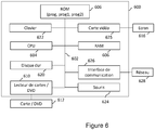
- the figure 6 illustrates an example of a device that can be used to implement, at least partially, one embodiment, in particular the steps described with reference to FIG. figure 3 .
- the device 600 is for example a server, a computer or a calculating assistant.
- the communication bus allows communication and interoperability between the various elements included in the device 600 or connected to it.
- the representation of the bus is not limiting and, in particular, the central unit is able to communicate instructions to any element of the device 600 directly or via another element of the device 600.
- the executable code of each program enabling the programmable apparatus to implement the processes according to the invention, in particular for modeling the magnetization of a ship, for calculating a magnetic field according to one or more predetermined planes and / or adjusting Immunization circuits can be stored, for example, in the hard disk 620 or in the read-only memory 606.
- the executable code of the programs may be received via the communication network 628, via the interface 626, to be stored in the same manner as that described previously.
- program or programs may be loaded into one of the storage means of the device 600 before being executed.
- the central unit 604 will control and direct the execution of the instructions or portions of software code of the program or programs according to the invention, instructions which are stored in the hard disk 620 or in the read-only memory 606 or else in the other elements of aforementioned storage.
- the program or programs that are stored in a non-volatile memory, for example the hard disk 620 or the read-only memory 606, are transferred into the random access memory 608 which then contains the executable code of the program or programs according to the invention, as well as registers for storing the variables and parameters necessary for the implementation of the invention.
- the invention may, according to some embodiments, be implemented using an aerial drone, it is also possible to use a submarine drone or a drone of surface to perform magnetic measurements.
- the invention may, according to some embodiments, be implemented with an autonomous mobile machine comprising a plurality of parts movably connected to one another.
- an autonomous mobile machine may in particular comprise a part having the magnetic measurement component or components, a part having the guide element or elements and, where appropriate, a part having communication means.
- the magnetic measurements can be made by several autonomous mobile machines of the same type or of different types. It is thus possible to use an aerial drone to perform part of the measurements and another drone, for example an aerial drone, a surface drone or an underwater drone to perform another part of the magnetic measurements.
- the autonomous mobile machine (s) used may comprise one or more magnetic sensors.
- the data from each of these sensors can be transmitted to be processed and to model a magnetization of the ship or can be consolidated before being transmitted in order to limit the number of transmitted data.
- Such consolidation can be carried out in a conventional manner, for example in by means of, with or without weighting, the data obtained by each sensor.
Landscapes
- Physics & Mathematics (AREA)
- Life Sciences & Earth Sciences (AREA)
- Engineering & Computer Science (AREA)
- Remote Sensing (AREA)
- General Physics & Mathematics (AREA)
- Geology (AREA)
- Environmental & Geological Engineering (AREA)
- General Life Sciences & Earth Sciences (AREA)
- Electromagnetism (AREA)
- Geophysics (AREA)
- Geochemistry & Mineralogy (AREA)
- Condensed Matter Physics & Semiconductors (AREA)
- Aviation & Aerospace Engineering (AREA)
- Navigation (AREA)
- Geophysics And Detection Of Objects (AREA)
- Inspection Of Paper Currency And Valuable Securities (AREA)
Claims (14)
- Verfahren zur Messung und Steuerung einer magnetischen Signatur eines Schiffes (100) unter Verwendung zumindest einer Drohne (110), die mit zumindest einem Magnetsensor (120) versehen ist, wobei das Verfahren dadurch gekennzeichnet ist, dass es die folgenden Schritte umfasst:- Erhalten (310) mehrerer magnetischer Messungen und zugehöriger Positionen, wobei die erhaltenen magnetischen Messungen ferner einer Fahrtrichtung des Schiffes zugeordnet sind;- Modellierung (325) einer Magnetisierung des Schiffes anhand der erhaltenen magnetischen Messungen, der zugehörigen Positionen und zumindest einer Fahrtrichtung des Schiffes;- Schätzen (330) von zumindest einem Magnetfeld gemäß der Modellierung der Magnetisierung des Schiffes und von zumindest einem Navigationsparameter des Schiffes; und- Steuern (335) eines Systems zur Verringerung der magnetischen Signatur des Schiffes anhand des zumindest einen geschätzten Magnetfeldes,
dadurch gekennzeichnet, dass
die Drohne eine Luftdrohne ist. - Verfahren nach Anspruch 1, wobei die zumindest eine Luftdrohne Kommunikationsmittel zur Kommunikation mit dem Schiff enthält, wobei das Verfahren ferner einen Schritt des Übertragens der mehreren magnetischen Messungen und der zugehörigen Positionen an ein Datenverarbeitungssystem des Schiffes enthält, wobei das Datenverarbeitungssystem des Schiffes die Schritte des Modellierens, des Schätzens von zumindest einem Magnetfeld und des Steuerns des Systems zur Verringerung der magnetischen Signatur des Schiffes durchführt, wobei das System zur Verringerung der magnetischen Signatur ein System zur Immunisierung des Schiffes enthält.
- Verfahren nach Anspruch 1 oder Anspruch 2, wobei die magnetischen Messungen für zumindest zwei geradlinige Bewegungsbahnen der zumindest einen Luftdrohne, die sich in der Nähe des Schiffes bewegt, erhalten werden.
- Verfahren nach einem der Ansprüche 1 bis 3, wobei die magnetischen Messungen für zumindest zwei verschiedene Fahrtrichtungen des Schiffes erhalten werden.
- Verfahren nach einem der Ansprüche 1 bis 4, wobei die magnetischen Messungen in einer im Wesentlichen konstanten Höhe, die in Abhängigkeit von der Überwasserhöhe bzw. dem Tiefgang des Schiffes bestimmt wird, erhalten werden.
- Verfahren nach einem der Ansprüche 1 bis 5, wobei der zumindest eine Magnetsensor ein Magnetsensor mit drei Achsen ist, von denen jeweils zwei senkrecht zueinander verlaufen, wobei die erhaltenen magnetischen Messungen die Norm eines vom Magnetsensor stammenden Vektors mit drei Komponenten darstellen.
- Verfahren nach Anspruch 6, ferner umfassend eine Kalibrationsphase (300) mit einem Schritt des Messens und Korrigierens von einem Nullfehler, einen Schritt des Messens und Korrigierens von einem Nullfehler der Empfindlichkeit und/oder einen Schritt des Messens und Korrigierens von einem Orthogonalitätsfehler der drei Achsen des Magnetsensors.
- Verfahren nach einem der Ansprüche 1 bis 7, ferner umfassend eine Kompensationsphase zum Kompensieren von dem magnetischen Einfluss der zumindest einen Luftdrohne auf den zumindest einen Magnetsensor.
- Verfahren nach einem der Ansprüche 1 bis 8, wobei die Schritte des Erhaltens mehrerer magnetischer Messungen, des Modellierens einer Magnetisierung des Schiffes, des Schätzens eines Magnetfeldes und des Steuerns eines Systems zur Verringerung der magnetischen Signatur zur Feinabstimmung des Systems zur Verringerung der magnetischen Signatur wiederholt werden.
- Anordnung zur Messung und Steuerung einer magnetischen Signatur eines Schiffes (100), wobei die Anordnung zumindest eine Drohne (110) enthält, die mit zumindest einem Magnetsensor (120) versehen ist, wobei die zumindest eine Luftdrohne dazu ausgelegt ist, mehrere magnetische Messungen und zugehörige Postionen zu erhalten (310), wobei die erhaltenen magnetischen Messungen einer Fahrtrichtung des Schiffes zugeordnet werden, wobei die Anordnung ferner Rechenmittel enthält, die dazu ausgelegt sind, eine Magnetisierung des Schiffes anhand der erhaltenen magnetischen Messungen, der zugehörigen Positionen und einer Fahrtrichtung des Schiffes zu modellieren (325), zumindest ein Magnetfeld gemäß einer Modellierung der Magnetisierung des Schiffes und zumindest einen Navigationsparameter des Schiffes zu schätzen (330) und ein System zur Verringerung der magnetischen Signatur anhand von zumindest einem geschätzten Magnetfeld zu steuern (335),
dadurch gekennzeichnet, dass
die Drohne eine Luftdrohne ist. - Anordnung nach Anspruch 10, wobei die Rechenmittel ferner dazu ausgelegt sind, Bewegungen der zumindest einen Luftdrohne entlang von zumindest zwei verschiedenen Bewegungsbahnen für zumindest zwei verschiedene Fahrtrichtungen des Schiffes in einer im Wesentlichen konstanten Höhe, die in Abhängigkeit von der Überwasserhöhe bzw. dem Tiefgang des Schiffes bestimmt ist, zu steuern.
- Anordnung nach Anspruch 10 oder Anspruch 11, wobei das System zur Verringerung der magnetischen Signatur ein System zur Immunisierung des Schiffes enthält.
- Anordnung nach einem der Ansprüche 10 bis 12, wobei die Rechenmittel Schiffsberechnungsmittel enthalten, wobei die Anordnung ferner Kommunikationsmittel enthält, die dazu ausgelegt sind, die mehreren magnetischen Messungen und zugehörigen Positionen an die Schiffsberechnungsmittel zu übertragen.
- Anordnung nach Anspruch 10 oder Anspruch 11, wobei das System zur Verringerung der magnetischen Signatur ein System zum Entmagnetisieren des Schiffes enthält.
Applications Claiming Priority (2)
| Application Number | Priority Date | Filing Date | Title |
|---|---|---|---|
| FR1559920A FR3042604B1 (fr) | 2015-10-16 | 2015-10-16 | Procede et dispositif de mesures magnetiques mobiles pour controler la signature magnetique d'un navire |
| PCT/FR2016/052654 WO2017064432A1 (fr) | 2015-10-16 | 2016-10-13 | Procédé et dispositif de mesures magnétiques mobiles pour contrôler la signature magnétique d'un navire |
Publications (2)
| Publication Number | Publication Date |
|---|---|
| EP3362811A1 EP3362811A1 (de) | 2018-08-22 |
| EP3362811B1 true EP3362811B1 (de) | 2019-08-28 |
Family
ID=55178145
Family Applications (1)
| Application Number | Title | Priority Date | Filing Date |
|---|---|---|---|
| EP16793963.6A Active EP3362811B1 (de) | 2015-10-16 | 2016-10-13 | Verfahren und vorrichtung für mobile magnetische messungen zur kontrolle der magnetischen signatur eines schiffes |
Country Status (7)
| Country | Link |
|---|---|
| EP (1) | EP3362811B1 (de) |
| AU (1) | AU2016337175B2 (de) |
| DK (1) | DK3362811T3 (de) |
| FR (1) | FR3042604B1 (de) |
| IL (1) | IL258693B (de) |
| SG (1) | SG11201803150WA (de) |
| WO (1) | WO2017064432A1 (de) |
Families Citing this family (2)
| Publication number | Priority date | Publication date | Assignee | Title |
|---|---|---|---|---|
| FR3142999B1 (fr) | 2022-12-13 | 2024-11-29 | Eca Robotics | Procédé et dispositif de gestion d’une signature magnétique d’un navire, produit programme d'ordinateur et médium de stockage correspondants |
| KR102909131B1 (ko) * | 2025-06-02 | 2026-01-07 | (주)케이엠넷 | 함정자기 현장 측정 장치 및 방법 |
Family Cites Families (4)
| Publication number | Priority date | Publication date | Assignee | Title |
|---|---|---|---|---|
| GB8327853D0 (en) * | 1983-10-18 | 1986-08-20 | Secr Defence | Magnetic self-ranging system |
| WO1987002324A1 (en) * | 1985-10-18 | 1987-04-23 | The Secretary Of State For Defence In Her Britanni | A magnetic self-ranging system for use in the degaussing of ships |
| FR2704065A1 (fr) * | 1991-12-26 | 1994-10-21 | Thomson Csf | Dispositif de mesure de la signature magnétique d'un bâtiment naval et son application au réglage de l'immunisation magnétique. |
| JP4259327B2 (ja) * | 2004-01-08 | 2009-04-30 | 株式会社島津製作所 | 艦艇の磁気測定方法 |
-
2015
- 2015-10-16 FR FR1559920A patent/FR3042604B1/fr not_active Expired - Fee Related
-
2016
- 2016-10-13 DK DK16793963T patent/DK3362811T3/da active
- 2016-10-13 WO PCT/FR2016/052654 patent/WO2017064432A1/fr not_active Ceased
- 2016-10-13 SG SG11201803150WA patent/SG11201803150WA/en unknown
- 2016-10-13 EP EP16793963.6A patent/EP3362811B1/de active Active
- 2016-10-13 AU AU2016337175A patent/AU2016337175B2/en active Active
-
2018
- 2018-04-15 IL IL258693A patent/IL258693B/en unknown
Non-Patent Citations (1)
| Title |
|---|
| None * |
Also Published As
| Publication number | Publication date |
|---|---|
| WO2017064432A1 (fr) | 2017-04-20 |
| SG11201803150WA (en) | 2018-05-30 |
| IL258693B (en) | 2022-06-01 |
| FR3042604A1 (fr) | 2017-04-21 |
| AU2016337175B2 (en) | 2022-07-07 |
| DK3362811T3 (da) | 2019-12-02 |
| IL258693A (en) | 2018-06-28 |
| FR3042604B1 (fr) | 2019-06-07 |
| AU2016337175A1 (en) | 2018-05-31 |
| EP3362811A1 (de) | 2018-08-22 |
Similar Documents
| Publication | Publication Date | Title |
|---|---|---|
| EP2313862B1 (de) | Verfahren und einrichtung zur fernsteuerung einer kamera an bord einer mobilstation | |
| EP3323028B1 (de) | Verfahren zur automatischen unterstützung der landung eines flugzeuges | |
| EP2932182B1 (de) | Verfahren zur genauen geolokalisierung eines bildsensors an bord eines flugzeugs | |
| US20190041856A1 (en) | Methods and apparatus to capture tomograms of structures using unmanned aerial vehicles | |
| US9639088B2 (en) | Autonomous long-range landing using sensor data | |
| EP3273318B1 (de) | Autonomes aufnahmesystem von animierten bildern durch eine drohne mit zielverfolgung und verbesserter lokalisierung des ziels | |
| EP2932341B1 (de) | Verfahren zum steuern einer gruppe von robotern und gruppe von robotern | |
| EP3271789B1 (de) | Automatisches hilfsverfahren zur landung eines luftfahrzeugs | |
| FR3031402A1 (fr) | Procede de pilotage automatique d'un drone a voilure tournante pour operer des mouvements de camera par une camera embarquee | |
| JP2010202178A5 (de) | ||
| EP3388914A1 (de) | Zielverfolgungsverfahren durch eine drohne, entsprechende software, entsprechendes elektronisches system und entsprechende drohne | |
| US11656365B2 (en) | Geolocation with aerial and satellite photography | |
| FR3057966A1 (fr) | Drone pilote dans un repere spherique par une gestuelle a plusieurs segments de membres, procede de pilotage et programme d'ordinateur associes | |
| EP3276591A1 (de) | Drohne mit einem hindernisausweichsystem | |
| FR3041121A1 (fr) | Procede de controle d'un aeronef suiveur par rapport a des tourbillons generes par un aeronef meneur | |
| EP3362811B1 (de) | Verfahren und vorrichtung für mobile magnetische messungen zur kontrolle der magnetischen signatur eines schiffes | |
| FR3050524B1 (fr) | Procede d'estimation du mouvement d'un objet evoluant dans un champ magnetique | |
| FR3151667A1 (fr) | Essaim de drones à positionnement collaboratif par communication ultra-large bande et procédé de positionnement associé | |
| EP3333539A1 (de) | Elektronische vorrichtung zum steuern einer drohne, entsprechende drohne, entsprechendes steuerverfahren und computerprogramm | |
| US20220358764A1 (en) | Change detection and characterization of assets | |
| US11464168B2 (en) | Automated vegetation removal | |
| Jayasiri et al. | AUV‐Based Plume Tracking: A Simulation Study | |
| EP3620852A1 (de) | Luftbildaufnahmeverfahren einer geografischen zone, 3d-kartografieverfahren einer geografischen zone und luftfahrzeug zur ausführung dieses verfahren | |
| EP4031834B1 (de) | Verfahren und system zum positionieren eines fahrzeugs unter verwendung einer bildaufnahmevorrichtung | |
| FR3071624B1 (fr) | Systeme d'affichage, procede d'affichage et programme d'ordinateur associes |
Legal Events
| Date | Code | Title | Description |
|---|---|---|---|
| STAA | Information on the status of an ep patent application or granted ep patent |
Free format text: STATUS: UNKNOWN |
|
| STAA | Information on the status of an ep patent application or granted ep patent |
Free format text: STATUS: THE INTERNATIONAL PUBLICATION HAS BEEN MADE |
|
| PUAI | Public reference made under article 153(3) epc to a published international application that has entered the european phase |
Free format text: ORIGINAL CODE: 0009012 |
|
| STAA | Information on the status of an ep patent application or granted ep patent |
Free format text: STATUS: REQUEST FOR EXAMINATION WAS MADE |
|
| 17P | Request for examination filed |
Effective date: 20180516 |
|
| AK | Designated contracting states |
Kind code of ref document: A1 Designated state(s): AL AT BE BG CH CY CZ DE DK EE ES FI FR GB GR HR HU IE IS IT LI LT LU LV MC MK MT NL NO PL PT RO RS SE SI SK SM TR |
|
| AX | Request for extension of the european patent |
Extension state: BA ME |
|
| RIN1 | Information on inventor provided before grant (corrected) |
Inventor name: PERIOU, JEAN-JACQUES Inventor name: NOVELLI, PHILIPPE Inventor name: MUNSCHY, MARC |
|
| DAV | Request for validation of the european patent (deleted) | ||
| DAX | Request for extension of the european patent (deleted) | ||
| GRAP | Despatch of communication of intention to grant a patent |
Free format text: ORIGINAL CODE: EPIDOSNIGR1 |
|
| STAA | Information on the status of an ep patent application or granted ep patent |
Free format text: STATUS: GRANT OF PATENT IS INTENDED |
|
| INTG | Intention to grant announced |
Effective date: 20190222 |
|
| GRAS | Grant fee paid |
Free format text: ORIGINAL CODE: EPIDOSNIGR3 |
|
| GRAA | (expected) grant |
Free format text: ORIGINAL CODE: 0009210 |
|
| STAA | Information on the status of an ep patent application or granted ep patent |
Free format text: STATUS: THE PATENT HAS BEEN GRANTED |
|
| RAP1 | Party data changed (applicant data changed or rights of an application transferred) |
Owner name: ECA ROBOTICS |
|
| RAP1 | Party data changed (applicant data changed or rights of an application transferred) |
Owner name: ECA ROBOTICS |
|
| AK | Designated contracting states |
Kind code of ref document: B1 Designated state(s): AL AT BE BG CH CY CZ DE DK EE ES FI FR GB GR HR HU IE IS IT LI LT LU LV MC MK MT NL NO PL PT RO RS SE SI SK SM TR |
|
| REG | Reference to a national code |
Ref country code: GB Ref legal event code: FG4D Free format text: NOT ENGLISH |
|
| REG | Reference to a national code |
Ref country code: CH Ref legal event code: EP |
|
| REG | Reference to a national code |
Ref country code: DE Ref legal event code: R096 Ref document number: 602016019592 Country of ref document: DE |
|
| REG | Reference to a national code |
Ref country code: AT Ref legal event code: REF Ref document number: 1173070 Country of ref document: AT Kind code of ref document: T Effective date: 20190915 |
|
| REG | Reference to a national code |
Ref country code: IE Ref legal event code: FG4D Free format text: LANGUAGE OF EP DOCUMENT: FRENCH |
|
| REG | Reference to a national code |
Ref country code: DK Ref legal event code: T3 Effective date: 20191129 |
|
| REG | Reference to a national code |
Ref country code: LT Ref legal event code: MG4D |
|
| REG | Reference to a national code |
Ref country code: NL Ref legal event code: FP |
|
| PG25 | Lapsed in a contracting state [announced via postgrant information from national office to epo] |
Ref country code: NO Free format text: LAPSE BECAUSE OF FAILURE TO SUBMIT A TRANSLATION OF THE DESCRIPTION OR TO PAY THE FEE WITHIN THE PRESCRIBED TIME-LIMIT Effective date: 20191128 Ref country code: BG Free format text: LAPSE BECAUSE OF FAILURE TO SUBMIT A TRANSLATION OF THE DESCRIPTION OR TO PAY THE FEE WITHIN THE PRESCRIBED TIME-LIMIT Effective date: 20191128 Ref country code: SE Free format text: LAPSE BECAUSE OF FAILURE TO SUBMIT A TRANSLATION OF THE DESCRIPTION OR TO PAY THE FEE WITHIN THE PRESCRIBED TIME-LIMIT Effective date: 20190828 Ref country code: PT Free format text: LAPSE BECAUSE OF FAILURE TO SUBMIT A TRANSLATION OF THE DESCRIPTION OR TO PAY THE FEE WITHIN THE PRESCRIBED TIME-LIMIT Effective date: 20191230 Ref country code: FI Free format text: LAPSE BECAUSE OF FAILURE TO SUBMIT A TRANSLATION OF THE DESCRIPTION OR TO PAY THE FEE WITHIN THE PRESCRIBED TIME-LIMIT Effective date: 20190828 Ref country code: LT Free format text: LAPSE BECAUSE OF FAILURE TO SUBMIT A TRANSLATION OF THE DESCRIPTION OR TO PAY THE FEE WITHIN THE PRESCRIBED TIME-LIMIT Effective date: 20190828 Ref country code: HR Free format text: LAPSE BECAUSE OF FAILURE TO SUBMIT A TRANSLATION OF THE DESCRIPTION OR TO PAY THE FEE WITHIN THE PRESCRIBED TIME-LIMIT Effective date: 20190828 |
|
| PG25 | Lapsed in a contracting state [announced via postgrant information from national office to epo] |
Ref country code: AL Free format text: LAPSE BECAUSE OF FAILURE TO SUBMIT A TRANSLATION OF THE DESCRIPTION OR TO PAY THE FEE WITHIN THE PRESCRIBED TIME-LIMIT Effective date: 20190828 Ref country code: LV Free format text: LAPSE BECAUSE OF FAILURE TO SUBMIT A TRANSLATION OF THE DESCRIPTION OR TO PAY THE FEE WITHIN THE PRESCRIBED TIME-LIMIT Effective date: 20190828 Ref country code: IS Free format text: LAPSE BECAUSE OF FAILURE TO SUBMIT A TRANSLATION OF THE DESCRIPTION OR TO PAY THE FEE WITHIN THE PRESCRIBED TIME-LIMIT Effective date: 20191228 Ref country code: GR Free format text: LAPSE BECAUSE OF FAILURE TO SUBMIT A TRANSLATION OF THE DESCRIPTION OR TO PAY THE FEE WITHIN THE PRESCRIBED TIME-LIMIT Effective date: 20191129 Ref country code: RS Free format text: LAPSE BECAUSE OF FAILURE TO SUBMIT A TRANSLATION OF THE DESCRIPTION OR TO PAY THE FEE WITHIN THE PRESCRIBED TIME-LIMIT Effective date: 20190828 Ref country code: ES Free format text: LAPSE BECAUSE OF FAILURE TO SUBMIT A TRANSLATION OF THE DESCRIPTION OR TO PAY THE FEE WITHIN THE PRESCRIBED TIME-LIMIT Effective date: 20190828 |
|
| REG | Reference to a national code |
Ref country code: AT Ref legal event code: MK05 Ref document number: 1173070 Country of ref document: AT Kind code of ref document: T Effective date: 20190828 |
|
| PG25 | Lapsed in a contracting state [announced via postgrant information from national office to epo] |
Ref country code: TR Free format text: LAPSE BECAUSE OF FAILURE TO SUBMIT A TRANSLATION OF THE DESCRIPTION OR TO PAY THE FEE WITHIN THE PRESCRIBED TIME-LIMIT Effective date: 20190828 |
|
| PG25 | Lapsed in a contracting state [announced via postgrant information from national office to epo] |
Ref country code: EE Free format text: LAPSE BECAUSE OF FAILURE TO SUBMIT A TRANSLATION OF THE DESCRIPTION OR TO PAY THE FEE WITHIN THE PRESCRIBED TIME-LIMIT Effective date: 20190828 Ref country code: PL Free format text: LAPSE BECAUSE OF FAILURE TO SUBMIT A TRANSLATION OF THE DESCRIPTION OR TO PAY THE FEE WITHIN THE PRESCRIBED TIME-LIMIT Effective date: 20190828 Ref country code: AT Free format text: LAPSE BECAUSE OF FAILURE TO SUBMIT A TRANSLATION OF THE DESCRIPTION OR TO PAY THE FEE WITHIN THE PRESCRIBED TIME-LIMIT Effective date: 20190828 Ref country code: RO Free format text: LAPSE BECAUSE OF FAILURE TO SUBMIT A TRANSLATION OF THE DESCRIPTION OR TO PAY THE FEE WITHIN THE PRESCRIBED TIME-LIMIT Effective date: 20190828 |
|
| PG25 | Lapsed in a contracting state [announced via postgrant information from national office to epo] |
Ref country code: MC Free format text: LAPSE BECAUSE OF FAILURE TO SUBMIT A TRANSLATION OF THE DESCRIPTION OR TO PAY THE FEE WITHIN THE PRESCRIBED TIME-LIMIT Effective date: 20190828 Ref country code: CZ Free format text: LAPSE BECAUSE OF FAILURE TO SUBMIT A TRANSLATION OF THE DESCRIPTION OR TO PAY THE FEE WITHIN THE PRESCRIBED TIME-LIMIT Effective date: 20190828 Ref country code: SK Free format text: LAPSE BECAUSE OF FAILURE TO SUBMIT A TRANSLATION OF THE DESCRIPTION OR TO PAY THE FEE WITHIN THE PRESCRIBED TIME-LIMIT Effective date: 20190828 Ref country code: SM Free format text: LAPSE BECAUSE OF FAILURE TO SUBMIT A TRANSLATION OF THE DESCRIPTION OR TO PAY THE FEE WITHIN THE PRESCRIBED TIME-LIMIT Effective date: 20190828 Ref country code: IS Free format text: LAPSE BECAUSE OF FAILURE TO SUBMIT A TRANSLATION OF THE DESCRIPTION OR TO PAY THE FEE WITHIN THE PRESCRIBED TIME-LIMIT Effective date: 20200224 |
|
| REG | Reference to a national code |
Ref country code: CH Ref legal event code: PL |
|
| REG | Reference to a national code |
Ref country code: DE Ref legal event code: R097 Ref document number: 602016019592 Country of ref document: DE |
|
| PLBE | No opposition filed within time limit |
Free format text: ORIGINAL CODE: 0009261 |
|
| STAA | Information on the status of an ep patent application or granted ep patent |
Free format text: STATUS: NO OPPOSITION FILED WITHIN TIME LIMIT |
|
| PG2D | Information on lapse in contracting state deleted |
Ref country code: IS |
|
| PG25 | Lapsed in a contracting state [announced via postgrant information from national office to epo] |
Ref country code: LI Free format text: LAPSE BECAUSE OF NON-PAYMENT OF DUE FEES Effective date: 20191031 Ref country code: CH Free format text: LAPSE BECAUSE OF NON-PAYMENT OF DUE FEES Effective date: 20191031 Ref country code: LU Free format text: LAPSE BECAUSE OF NON-PAYMENT OF DUE FEES Effective date: 20191013 |
|
| 26N | No opposition filed |
Effective date: 20200603 |
|
| PG25 | Lapsed in a contracting state [announced via postgrant information from national office to epo] |
Ref country code: SI Free format text: LAPSE BECAUSE OF FAILURE TO SUBMIT A TRANSLATION OF THE DESCRIPTION OR TO PAY THE FEE WITHIN THE PRESCRIBED TIME-LIMIT Effective date: 20190828 |
|
| PG25 | Lapsed in a contracting state [announced via postgrant information from national office to epo] |
Ref country code: IE Free format text: LAPSE BECAUSE OF NON-PAYMENT OF DUE FEES Effective date: 20191013 |
|
| PG25 | Lapsed in a contracting state [announced via postgrant information from national office to epo] |
Ref country code: CY Free format text: LAPSE BECAUSE OF FAILURE TO SUBMIT A TRANSLATION OF THE DESCRIPTION OR TO PAY THE FEE WITHIN THE PRESCRIBED TIME-LIMIT Effective date: 20190828 |
|
| PG25 | Lapsed in a contracting state [announced via postgrant information from national office to epo] |
Ref country code: MT Free format text: LAPSE BECAUSE OF FAILURE TO SUBMIT A TRANSLATION OF THE DESCRIPTION OR TO PAY THE FEE WITHIN THE PRESCRIBED TIME-LIMIT Effective date: 20190828 Ref country code: HU Free format text: LAPSE BECAUSE OF FAILURE TO SUBMIT A TRANSLATION OF THE DESCRIPTION OR TO PAY THE FEE WITHIN THE PRESCRIBED TIME-LIMIT; INVALID AB INITIO Effective date: 20161013 |
|
| PG25 | Lapsed in a contracting state [announced via postgrant information from national office to epo] |
Ref country code: MK Free format text: LAPSE BECAUSE OF FAILURE TO SUBMIT A TRANSLATION OF THE DESCRIPTION OR TO PAY THE FEE WITHIN THE PRESCRIBED TIME-LIMIT Effective date: 20190828 |
|
| PGFP | Annual fee paid to national office [announced via postgrant information from national office to epo] |
Ref country code: GB Payment date: 20250929 Year of fee payment: 10 |
|
| PGFP | Annual fee paid to national office [announced via postgrant information from national office to epo] |
Ref country code: FR Payment date: 20250926 Year of fee payment: 10 |
|
| PGFP | Annual fee paid to national office [announced via postgrant information from national office to epo] |
Ref country code: NL Payment date: 20251029 Year of fee payment: 10 |
|
| PGFP | Annual fee paid to national office [announced via postgrant information from national office to epo] |
Ref country code: DE Payment date: 20251029 Year of fee payment: 10 |
|
| PGFP | Annual fee paid to national office [announced via postgrant information from national office to epo] |
Ref country code: DK Payment date: 20251029 Year of fee payment: 10 Ref country code: IT Payment date: 20251029 Year of fee payment: 10 |
|
| PGFP | Annual fee paid to national office [announced via postgrant information from national office to epo] |
Ref country code: BE Payment date: 20251029 Year of fee payment: 10 |