EP3362746B1 - Joule thomson aided stirling cycle cooler - Google Patents
Joule thomson aided stirling cycle cooler Download PDFInfo
- Publication number
- EP3362746B1 EP3362746B1 EP16756905.2A EP16756905A EP3362746B1 EP 3362746 B1 EP3362746 B1 EP 3362746B1 EP 16756905 A EP16756905 A EP 16756905A EP 3362746 B1 EP3362746 B1 EP 3362746B1
- Authority
- EP
- European Patent Office
- Prior art keywords
- heat exchanger
- chamber
- adapter
- thermal load
- refrigerant
- Prior art date
- Legal status (The legal status is an assumption and is not a legal conclusion. Google has not performed a legal analysis and makes no representation as to the accuracy of the status listed.)
- Active
Links
Images



Classifications
-
- F—MECHANICAL ENGINEERING; LIGHTING; HEATING; WEAPONS; BLASTING
- F25—REFRIGERATION OR COOLING; COMBINED HEATING AND REFRIGERATION SYSTEMS; HEAT PUMP SYSTEMS; MANUFACTURE OR STORAGE OF ICE; LIQUEFACTION SOLIDIFICATION OF GASES
- F25B—REFRIGERATION MACHINES, PLANTS OR SYSTEMS; COMBINED HEATING AND REFRIGERATION SYSTEMS; HEAT PUMP SYSTEMS
- F25B9/00—Compression machines, plants or systems, in which the refrigerant is air or other gas of low boiling point
- F25B9/02—Compression machines, plants or systems, in which the refrigerant is air or other gas of low boiling point using Joule-Thompson effect; using vortex effect
-
- F—MECHANICAL ENGINEERING; LIGHTING; HEATING; WEAPONS; BLASTING
- F25—REFRIGERATION OR COOLING; COMBINED HEATING AND REFRIGERATION SYSTEMS; HEAT PUMP SYSTEMS; MANUFACTURE OR STORAGE OF ICE; LIQUEFACTION SOLIDIFICATION OF GASES
- F25B—REFRIGERATION MACHINES, PLANTS OR SYSTEMS; COMBINED HEATING AND REFRIGERATION SYSTEMS; HEAT PUMP SYSTEMS
- F25B49/00—Arrangement or mounting of control or safety devices
- F25B49/02—Arrangement or mounting of control or safety devices for compression type machines, plants or systems
-
- F—MECHANICAL ENGINEERING; LIGHTING; HEATING; WEAPONS; BLASTING
- F25—REFRIGERATION OR COOLING; COMBINED HEATING AND REFRIGERATION SYSTEMS; HEAT PUMP SYSTEMS; MANUFACTURE OR STORAGE OF ICE; LIQUEFACTION SOLIDIFICATION OF GASES
- F25B—REFRIGERATION MACHINES, PLANTS OR SYSTEMS; COMBINED HEATING AND REFRIGERATION SYSTEMS; HEAT PUMP SYSTEMS
- F25B9/00—Compression machines, plants or systems, in which the refrigerant is air or other gas of low boiling point
- F25B9/14—Compression machines, plants or systems, in which the refrigerant is air or other gas of low boiling point characterised by the cycle used, e.g. Stirling cycle
-
- F—MECHANICAL ENGINEERING; LIGHTING; HEATING; WEAPONS; BLASTING
- F25—REFRIGERATION OR COOLING; COMBINED HEATING AND REFRIGERATION SYSTEMS; HEAT PUMP SYSTEMS; MANUFACTURE OR STORAGE OF ICE; LIQUEFACTION SOLIDIFICATION OF GASES
- F25D—REFRIGERATORS; COLD ROOMS; ICE-BOXES; COOLING OR FREEZING APPARATUS NOT OTHERWISE PROVIDED FOR
- F25D19/00—Arrangement or mounting of refrigeration units with respect to devices or objects to be refrigerated, e.g. infrared detectors
- F25D19/006—Thermal coupling structure or interface
-
- G—PHYSICS
- G01—MEASURING; TESTING
- G01J—MEASUREMENT OF INTENSITY, VELOCITY, SPECTRAL CONTENT, POLARISATION, PHASE OR PULSE CHARACTERISTICS OF INFRARED, VISIBLE OR ULTRAVIOLET LIGHT; COLORIMETRY; RADIATION PYROMETRY
- G01J1/00—Photometry, e.g. photographic exposure meter
- G01J1/02—Details
- G01J1/0252—Constructional arrangements for compensating for fluctuations caused by, e.g. temperature, or using cooling or temperature stabilization of parts of the device; Controlling the atmosphere inside a photometer; Purge systems, cleaning devices
-
- F—MECHANICAL ENGINEERING; LIGHTING; HEATING; WEAPONS; BLASTING
- F25—REFRIGERATION OR COOLING; COMBINED HEATING AND REFRIGERATION SYSTEMS; HEAT PUMP SYSTEMS; MANUFACTURE OR STORAGE OF ICE; LIQUEFACTION SOLIDIFICATION OF GASES
- F25B—REFRIGERATION MACHINES, PLANTS OR SYSTEMS; COMBINED HEATING AND REFRIGERATION SYSTEMS; HEAT PUMP SYSTEMS
- F25B13/00—Compression machines, plants or systems, with reversible cycle
-
- F—MECHANICAL ENGINEERING; LIGHTING; HEATING; WEAPONS; BLASTING
- F25—REFRIGERATION OR COOLING; COMBINED HEATING AND REFRIGERATION SYSTEMS; HEAT PUMP SYSTEMS; MANUFACTURE OR STORAGE OF ICE; LIQUEFACTION SOLIDIFICATION OF GASES
- F25B—REFRIGERATION MACHINES, PLANTS OR SYSTEMS; COMBINED HEATING AND REFRIGERATION SYSTEMS; HEAT PUMP SYSTEMS
- F25B2313/00—Compression machines, plants or systems with reversible cycle not otherwise provided for
- F25B2313/003—Indoor unit with water as a heat sink or heat source
-
- F—MECHANICAL ENGINEERING; LIGHTING; HEATING; WEAPONS; BLASTING
- F25—REFRIGERATION OR COOLING; COMBINED HEATING AND REFRIGERATION SYSTEMS; HEAT PUMP SYSTEMS; MANUFACTURE OR STORAGE OF ICE; LIQUEFACTION SOLIDIFICATION OF GASES
- F25B—REFRIGERATION MACHINES, PLANTS OR SYSTEMS; COMBINED HEATING AND REFRIGERATION SYSTEMS; HEAT PUMP SYSTEMS
- F25B2313/00—Compression machines, plants or systems with reversible cycle not otherwise provided for
- F25B2313/023—Compression machines, plants or systems with reversible cycle not otherwise provided for using multiple indoor units
- F25B2313/0232—Compression machines, plants or systems with reversible cycle not otherwise provided for using multiple indoor units with bypasses
- F25B2313/02322—Compression machines, plants or systems with reversible cycle not otherwise provided for using multiple indoor units with bypasses during defrosting
-
- F—MECHANICAL ENGINEERING; LIGHTING; HEATING; WEAPONS; BLASTING
- F25—REFRIGERATION OR COOLING; COMBINED HEATING AND REFRIGERATION SYSTEMS; HEAT PUMP SYSTEMS; MANUFACTURE OR STORAGE OF ICE; LIQUEFACTION SOLIDIFICATION OF GASES
- F25B—REFRIGERATION MACHINES, PLANTS OR SYSTEMS; COMBINED HEATING AND REFRIGERATION SYSTEMS; HEAT PUMP SYSTEMS
- F25B2327/00—Compressor driving means
- F25B2327/10—Compressor driving means using engines
- F25B2327/12—Compressor driving means using engines using internal combustion engines
-
- F—MECHANICAL ENGINEERING; LIGHTING; HEATING; WEAPONS; BLASTING
- F25—REFRIGERATION OR COOLING; COMBINED HEATING AND REFRIGERATION SYSTEMS; HEAT PUMP SYSTEMS; MANUFACTURE OR STORAGE OF ICE; LIQUEFACTION SOLIDIFICATION OF GASES
- F25B—REFRIGERATION MACHINES, PLANTS OR SYSTEMS; COMBINED HEATING AND REFRIGERATION SYSTEMS; HEAT PUMP SYSTEMS
- F25B2400/00—Component parts or details not otherwise provided for in this subclass
- F25B2400/06—Several compression cycles arranged in parallel
-
- F—MECHANICAL ENGINEERING; LIGHTING; HEATING; WEAPONS; BLASTING
- F25—REFRIGERATION OR COOLING; COMBINED HEATING AND REFRIGERATION SYSTEMS; HEAT PUMP SYSTEMS; MANUFACTURE OR STORAGE OF ICE; LIQUEFACTION SOLIDIFICATION OF GASES
- F25B—REFRIGERATION MACHINES, PLANTS OR SYSTEMS; COMBINED HEATING AND REFRIGERATION SYSTEMS; HEAT PUMP SYSTEMS
- F25B2500/00—Problems to be solved
- F25B2500/19—Calculation of parameters
-
- F—MECHANICAL ENGINEERING; LIGHTING; HEATING; WEAPONS; BLASTING
- F25—REFRIGERATION OR COOLING; COMBINED HEATING AND REFRIGERATION SYSTEMS; HEAT PUMP SYSTEMS; MANUFACTURE OR STORAGE OF ICE; LIQUEFACTION SOLIDIFICATION OF GASES
- F25B—REFRIGERATION MACHINES, PLANTS OR SYSTEMS; COMBINED HEATING AND REFRIGERATION SYSTEMS; HEAT PUMP SYSTEMS
- F25B27/00—Machines, plants or systems, using particular sources of energy
Definitions
- the present disclosure is directed cooling systems, and more particularly to a quick system ready with a long operating time cooling device.
- Cryogenic coolers lift heat from infrared detectors and associated electronic and optical components in applications where space is limited.
- the cryogenic cooler is often inserted into a Dewar (or housing) onto which one or more detector elements are mounted.
- Current flight vehicle applications often require that an infrared focal plane array of detector elements be cooled to approximately liquid nitrogen temperatures, i.e., 77 K (-193°C).
- Joule-Thomson and Stirling Cycle coolers are the two cooling technologies most often used to provide controlled cooling at such temperatures for size and weight critical applications.
- a Joule-Thomson cooler is a device that produces liquid refrigerant by use of a valve (known in the art as a "Joule-Thomson valve") and counter flow heat exchanger. High-pressure gas is allowed to expand through the valve via an irreversible throttling process in which enthalpy is conserved, resulting in lowering of its temperature.
- the counter-flow heat exchanger transfers heat from the high-pressure incoming gas to the cooled exiting gas to decrease the enthalpy of the incoming gas and enable liquid production.
- the simplest form of a conventional Joule-Thomson cooler typically uses a fixed-size orifice near the heat exchanger at the cold end of the cooler such that cooling power is unregulated. The input pressure and internal gas flow dynamics establish the flow parameters of the refrigerant through the cooler.
- Joule-Thomson coolers require a supply of highly pressurized gas. In certain applications, such as flight vehicles, this requirement tends to impose significant logistical constraints. In the flight vehicle context, for example, only a limited amount of pressurized gas can be carried on the flight vehicle and the host vehicle. This limits the operating time of the weapons platform in proportion to the amount of pressurized gas onboard. After each mission, the gas containers must be recharged. Extended use of Joule-Thomson coolers increases the possibility of contamination due to small impurities that may block the fine orifice of the device. These constraints impose significant field maintenance requirements that limit the viability of Joule-Thomson cryostats for such demanding applications.
- a Stirling cycle cooler is an efficient and compact closed-cycle, electrically-driven cryogenic cooling device using a repeating reversible expansion of a gas. It consists of two main assemblies, a compressor and a cold head.
- the compressor provides a sinusoidal pressure wave to the cold head.
- Modern cold heads typically consists of an expansion piston and integral regenerative heat exchanger.
- the regenerative heat exchanger (regenerator) is included in the expansion piston to thermally isolate gas at the compressor headspace from gas at the expansion headspace. Refrigeration is provided at one end of the cold finger portion of the cold head.
- Stirling coolers are inherently slow to bring their thermal load to operating temperature but can run for long periods with only electrical power.
- Joule-Thomson coolers are much quicker to bring their load to operating temperature but require large amounts of size and weight to run for long periods.
- Various improvements to the Joule-Thomson technology have been implemented to increase system operating time but these systems do not approach the operating times of a Stirling system.
- the physics of a Stirling cooler do not allow it to match the refrigeration power and quick ready time of a Joule-Thomson system in any reasonable size limit. The system designer has had to choose between the two types of coolers and compromise vehicle performance as a result.
- US 6 070 414 A discloses a cryogenic cooler and a dewar assembly including a cooled surface; a cooling surface for removing thermal energy from the cooled surface; and an adapter disposed between the cooling surface and the cooled surface for conducting thermal energy therebetween.
- a first fluid is disposed between the cooled surface and the adapter for conducting thermal energy from the cooled surface to the adapter.
- a second fluid is disposed between the cooling surface and the adapter for conducting thermal energy from the adapter to the cooling surface whereby the cooling surface remains free to move axially relative to the adapter at a temperature of the cooling surface at which the first fluid is susceptible to freezing.
- the present disclosure provides an apparatus comprising: a chamber; a first heat exchanger including a cold finger, wherein the cold finger is positioned within the chamber; a second heat exchanger within the chamber, wherein the second heat exchanger is a counter flow heat exchanger operable to precool refrigerant entering a Joule-Thomson valve; an adapter positioned between the cold finger and the second heat exchanger, the adapter operable to transfer heat from a thermal load to both the cold finger and the refrigerant emitted from the Joule-Thomson valve, wherein the second heat exchanger is positioned around the adapter.
- the present disclosure provides a cooling system for cooling a thermal load within a flight vehicle, the system comprising an apparatus according to the first aspect; wherein the chamber is locateble within a bulkhead of the flight vehicle.
- the present disclosure provides a method for cooling a thermal load, the method comprising: activating a first heat exchanger, wherein the first heat exchanger includes a cold finger of a cold head positioned within a chamber, and wherein an adapter is positioned around the cold finger; responsive to a determination to activate a second heat exchanger positioned around the adapter, activating the second heat exchanger with a high-pressure gas creating a refrigerant for Joule-Thomson expansion; and releasing, by a Joule-Thomson valve, the refrigerant into the chamber between the adapter and an inner wall of the chamber.
- FIGURE 1 illustrates an example flight vehicle 100 having a cooling system 102 in accordance with this disclosure.
- the flight vehicle 100 includes a bulkhead 101. Within the bulkhead 101 are a motor 104, a fuel 106, and a motor casing 108.
- the motor 104 uses the fuel 106 to generate thrust for the flight vehicle 100.
- the motor 104 denotes any suitable structure for generating thrust for a flight vehicle
- the fuel 106 denotes any suitable fuel used by a motor for generating thrust for a flight vehicle.
- the motor 104 represents a rocket motor
- the fuel 106 represents a solid rocket fuel.
- the motor casing 108 encases the motor 104 and the fuel 106, and fins or other structures are routinely mounted on the motor casing 108.
- the motor casing 108 is typically formed from metal or other structurally-reinforcing material(s).
- the flight vehicle 100 includes a cooling system 102 and an infrared (IR) detector 120.
- the IR detector 120 and its surrounding structure may have its temperature decreased to reduce its photon noise and background irradiance in order to improve the system sensitivity.
- FIGURE 1 illustrates one example of a flight vehicle 100 having a cooling system
- various changes may be made to FIGURE 1 .
- the cooling system 102 could be used with any other suitable flight vehicle or other system where cooling is needed or desired.
- IR detectors often need to be cooled to cryogenic temperatures to enable adequate system performance. Extended system operating times often dictate the use of Stirling cooler technology. However, Stirling coolers have limited refrigeration power and can take minutes to reach operating temperature from initial turn-on. The utility of a weapon or surveillance system for many applications would be greatly expanded if the system could reach operating temperature much quicker.
- Various embodiments of this disclosure provide a cooling system to enable very quick system ready times.
- Various embodiments of this disclosure provide a cooling system that minimizes changes to the interfaces, primarily the detector Dewar assembly.
- the various embodiments provide operation of the Stirling cooler that can be quickly cooled for very quick ready times. The Stirling cooler would take over after cool down is achieved and normal Stirling operation would begin.
- Various embodiments of this disclosure provide a Joule-Thomson cooler for quick ready times and a Stirling cooler for long run times.
- the various embodiments integrate the Joule-Thomson valve and counter-flow heat exchanger with the cold finger of the Stirling cooler to minimize size and steady-state heat load increases. Boiling of the Joule-Thomson produced liquid refrigerant and heat exchange between the Stirling cold finger and the cold platform occur through the same part, thus minimizing added thermal mass. Integration also takes advantage of lost refrigeration power from Joule-Thomson heat exchanger inefficiency to cool the compression side of the Stirling cold head to increase Stirling cooler performance.
- FIGURE 2 illustrates a sectional side view of an illustrative implementation of a cooling system 200 in accordance with this disclosure.
- the cooling system 200 can be one example of cooling system 102 as shown in FIGURE 1 .
- the cooling system 200 is shown with a platform 202 to which a thermal load can be attached thereto.
- the cooling system 200 is mounted within a support structure such as a bulkhead 204.
- the bulkhead 204 may be made of aluminum or other suitable material.
- a cold finger 206 is secured into the warm end of the cold head 208.
- the cold head 208 and cold finger 206 may be made of any suitable material such as titanium, a nickel-based super alloy or stainless steel.
- the distal end of the cold finger 206 is slip fitted within an adapter 212 that is seated within a chamber 214.
- the chamber 214 can be housed in a vacuum flask, such as, for example, a Dewar.
- the outer wall of the chamber 214 may be made of titanium or other suitable material.
- the chamber 214 outer wall 218 forms the Dewar inner wall and is contained in the Dewar outer wall 216.
- the platform 202 for mounting the thermal load forms the end cap of the chamber 214.
- the chamber 214 is open at the proximal end of the cold finger 206.
- the adapter 212 is pressed against an end cap of the chamber 214 by a coiled spring 220.
- the coiled spring 220 or equivalent such as a material with a spring like quality or foam, acts against and transmits an axial spring force to the adapter 212 ensuring good thermal contact while minimizing parasitic thermal loads.
- the coiled spring 220 rests against the annular shoulders 210 of the cold head 208.
- the cold finger 206 can be part of a heat exchanger 221.
- the heat exchanger could be, for example, a Stirling cooler.
- the adapter 212 is configured to transfer heat away from the platform 202.
- the cold finger 206 may transfer heat from the thermal load through the adapter 212.
- the refrigerant exiting the J-T valve 224 may transfer heat from the thermal load though the adapter 212.
- the adapter 212 can transfer heat through conductivity.
- finned tubes 222 of a heat exchanger 223 are positioned within the chamber 214.
- the finned tubes 222 can be part of Hampson style heat exchanger which is part of a Joule-Thomson cooler.
- the finned tubes 222 are formed in a spiral formation around the adapter 212.
- other heat exchanger types can be used.
- a J-T valve 224 consisting of a small diameter capillary tube formed in a spiral formation around the adapter 212 resides at the end of the finned tube 222.
- other methods of throttling the high pressure gas in an isenthalpic manner can be used.
- the valve 224 allows the release of a refrigerant to flow from the inner portion of the finned tube 222 into the chamber 214.
- the refrigerant from the J-T valve 224 provides a faster cooling rate than the cold finger 206 when the cold head 206 is initially activated.
- FIGURE 2 illustrates one example of a cooling system 200
- the cooling system 200 could be used with any other system where cooling is needed or desired.
- the makeup and arrangement of the cooling system 200 in FIGURE 2 is for illustration only. Components could be added, omitted, combined, or placed in any other suitable configuration according to particular needs.
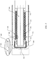
- FIGURE 3 illustrates a sectional side view of an illustrative implementation of a chamber 300 in accordance with this disclosure.
- the chamber 300 can be one example of the chamber 214 as shown in FIGURE 2 .
- the chamber 300 is shown with a platform 302 for mounting a thermal load attached thereto.
- the chamber 300 is mounted within a support structure such as a bulkhead.
- the chamber 300 includes a cold finger 306, an adapter 312, an outer wall 318, finned tubes 322, and J-T valve 324.
- the distal end of the cold head 306 is slip fitted within an adapter 312 that is seated within a chamber 300.
- the chamber 300 can be contained in a vacuum flask, such as, for example, a dewar.
- the chamber 300 may be made of titanium or other suitable material.
- the platform 302 for mounting the thermal load forms the end cap of the chamber 300.
- the chamber 300 is open as the proximal end of the cold finger 306.
- the outer wall 318 of the chamber 300 includes a thick portion 350 and a thin portion 352.
- the thin portion 352 allows for minimal thermal conduction while the thick portion 350 allows for increased thermal conduction.
- the J-T valve 324 are near the thick portion 350 allowing the refrigerant to primarily contact the thick portion 350 and increase thermal conduction to the platform 302.
- other features such as fin-like structures could also be added to aid boiling heat transfer.
- a thread shaped gasketing material is spirally wound with the heat exchanger tube 322 to improve heat exchanger efficiency, as is customary.
- a gap 360 exists between the adapter 312 and cold finger 306 to minimize thermal conduction between the heat exchanger and the cold finger 306. Near the distal end of the cold finger 306, the gap 360 can decrease and allow for a tight fit between the adapter 312 and cold finger 306 at portion 365 to provide thermal contact between the adapter 312 and the cold finger 306 at the coldest portion of the Stirling cold head.
- the cold finger 306 can be part of a heat exchanger.
- the heat exchanger could be, for example, a Stirling cooler.
- the cold finger 306 is configured to transfer heat away from the platform 302.
- the cold finger 306 may transfer heat from the thermal load through the adapter 312.
- the refrigerant exiting the J-T valve 324 may transfer heat from the thermal load through the adapter 312 or the enhanced portion of the outer wall 318.
- the adapter 312 can transfer heat through conductivity.
- the adapter 312 is configured to provide a thermal path between the thermal load and the Stirling cold finger 306 as well as a path between the thermal load and the refrigerant exiting the J-T valve 324.
- FIGURE 3 illustrates one example of a chamber 300
- the chamber 300 could be used with any other system where cooling is needed or desired.
- the makeup and arrangement of the chamber 300 in FIGURE 3 is for illustration only. Components could be added, omitted, combined, or placed in any other suitable configuration according to particular needs.
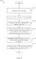
- FIGURE 4 illustrates a process 400 for cooling a thermal load in accordance with this disclosure.
- the process 400 can be implemented by the cooling system 200 as shown in FIGURE 2 .
- a processor can execute a set of instructions to perform the process 400.
- a processor is configured to, at 402, activate a first heat exchanger.
- the first heat exchanger can be a closed-cycle, electrically-driven cryogenic cooling device, such as, but not limited to a Stirling cooler.
- the first heat exchanger can include a cold head positioned within a chamber.
- the processor is configured to compare the estimated system need time to a time threshold.
- the estimated system need time can be determined from data pertinent to system operation and timeline.
- the time threshold can be predetermined.
- the processor is configured to compare a temperature of a thermal load to a temperature threshold.
- a sensor can measure the temperature of the thermal load in the cooling system.
- the temperature threshold can be predetermined.
- the processor is configured to determine whether to activate a second heat exchanger as a function of system need time, the temperature of the thermal load, and the predetermined time/temperature thresholds. In one example, if the system need time is imminent and if the temperature of the thermal load is greater than the temperature threshold, then the second heat exchanger can be activated because the thermal load is at such a temperature that additional cooling at the activation of the first heat exchanger is desired to meet system timing needs.
- the processor is configured to activate the second heat exchanger in response to a determination to activate the second heat exchanger.
- the second heat exchanger releases refrigerant into the chamber between the cold head and the inner wall of the chamber. The refrigerant quickly cools the thermal load prior to a full initialization of the first heat exchanger.
- FIGURE 4 illustrates one example of a process 400
- the second heat exchanger may be activated based on the system need time only.
- the second heat exchanger may always be activated when the first heat exchanger is activated.
- the second heat exchanger may be activated before the first heat exchanger.
- FIGURE 5 illustrates an example computer 500 that may be used for controlling a cooling system according to this disclosure.
- the device 500 includes a bus system 502, which supports communication between at least one processing device 504, at least one storage device 506, at least one communications unit 508, and at least one input/output (I/O) unit 510.
- I/O input/output
- the processing device 504 executes instructions that may be loaded into a memory 512.
- the processing device 504 may include any suitable number(s) and type(s) of processors or other devices in any suitable arrangement.
- Example types of processing devices 504 include microprocessors, microcontrollers, digital signal processors, field programmable gate arrays, application specific integrated circuits, and discrete circuitry.
- the memory 512 and a persistent storage 514 are examples of storage devices 506, which represent any structure(s) capable of storing and facilitating retrieval of information (such as data, program code, and/or other suitable information on a temporary or permanent basis).
- the memory 512 may represent a random access memory or any other suitable volatile or non-volatile storage device(s).
- the persistent storage 514 may contain one or more components or devices supporting longer-term storage of data, such as a ready only memory, hard drive, Flash memory, or optical disc.
- the communications unit 508 supports communications with other systems or devices.
- the communications unit 508 could include a network interface card that facilitates communications over at least one Ethernet network.
- the communications unit 508 could also include a wireless transceiver facilitating communications over at least one wireless network.
- the communications unit 508 may support communications through any suitable physical or wireless communication link(s).
- the I/O unit 510 allows for input and output of data.
- the I/O unit 510 may provide a connection for user input through a keyboard, mouse, keypad, touchscreen, or other suitable input device.
- the I/O unit 510 may also send output to a display, printer, or other suitable output device.
- FIGURES 1 through 3 illustrate example cooling systems
- various changes may be made to FIGURES 1 through 3 .
- well-known processes have not been described in detail and have been omitted for brevity.
- specific steps, structures and materials may have been described, this disclosure may not be limited to these specifics, and others may be substituted as it is well understood by those skilled in the art, and various steps may not necessarily be performed in the sequences shown.
- various functions described above are implemented or supported by a computer program that is formed from computer readable program code and that is embodied in a computer readable medium.
- computer readable program code includes any type of computer code, including source code, object code, and executable code.
- computer readable medium includes any type of medium capable of being accessed by a computer, such as read only memory (ROM), random access memory (RAM), a hard disk drive, a compact disc (CD), a digital video disc (DVD), or any other type of memory.
- ROM read only memory
- RAM random access memory
- CD compact disc
- DVD digital video disc
- a “non-transitory” computer readable medium excludes wired, wireless, optical, or other communication links that transport transitory electrical or other signals.
- a non-transitory computer readable medium includes media where data can be permanently stored and media where data can be stored and later overwritten, such as a rewritable optical disc or an erasable memory device.
- the term “or” is inclusive, meaning and/or.
Landscapes
- Engineering & Computer Science (AREA)
- Physics & Mathematics (AREA)
- Mechanical Engineering (AREA)
- Thermal Sciences (AREA)
- General Engineering & Computer Science (AREA)
- Chemical & Material Sciences (AREA)
- Combustion & Propulsion (AREA)
- Electromagnetism (AREA)
- General Physics & Mathematics (AREA)
- Spectroscopy & Molecular Physics (AREA)
Description
- The present disclosure is directed cooling systems, and more particularly to a quick system ready with a long operating time cooling device.
- Cryogenic coolers lift heat from infrared detectors and associated electronic and optical components in applications where space is limited. The cryogenic cooler is often inserted into a Dewar (or housing) onto which one or more detector elements are mounted. Current flight vehicle applications often require that an infrared focal plane array of detector elements be cooled to approximately liquid nitrogen temperatures, i.e., 77 K (-193°C). Joule-Thomson and Stirling Cycle coolers are the two cooling technologies most often used to provide controlled cooling at such temperatures for size and weight critical applications.
- A Joule-Thomson cooler is a device that produces liquid refrigerant by use of a valve (known in the art as a "Joule-Thomson valve") and counter flow heat exchanger. High-pressure gas is allowed to expand through the valve via an irreversible throttling process in which enthalpy is conserved, resulting in lowering of its temperature. The counter-flow heat exchanger transfers heat from the high-pressure incoming gas to the cooled exiting gas to decrease the enthalpy of the incoming gas and enable liquid production. The simplest form of a conventional Joule-Thomson cooler typically uses a fixed-size orifice near the heat exchanger at the cold end of the cooler such that cooling power is unregulated. The input pressure and internal gas flow dynamics establish the flow parameters of the refrigerant through the cooler.
- Joule-Thomson coolers require a supply of highly pressurized gas. In certain applications, such as flight vehicles, this requirement tends to impose significant logistical constraints. In the flight vehicle context, for example, only a limited amount of pressurized gas can be carried on the flight vehicle and the host vehicle. This limits the operating time of the weapons platform in proportion to the amount of pressurized gas onboard. After each mission, the gas containers must be recharged. Extended use of Joule-Thomson coolers increases the possibility of contamination due to small impurities that may block the fine orifice of the device. These constraints impose significant field maintenance requirements that limit the viability of Joule-Thomson cryostats for such demanding applications.
- Various improvements to the Joule-Thomson technology have been implemented to increase system operating time. These include various mechanisms to throttle back flow after cool down or systems that include a compressor instead of a gas bottle. Use of a compressor in place of a bottle can eliminate the need to recharge the gas container after each mission but comes with its own limitations and field maintenance requirements.
- For these and other reasons, Stirling cycle coolers tend to be preferred for such applications as they can run for thousands of hours on electrical power alone. A Stirling cycle cooler is an efficient and compact closed-cycle, electrically-driven cryogenic cooling device using a repeating reversible expansion of a gas. It consists of two main assemblies, a compressor and a cold head. The compressor provides a sinusoidal pressure wave to the cold head. Modern cold heads typically consists of an expansion piston and integral regenerative heat exchanger. The regenerative heat exchanger (regenerator) is included in the expansion piston to thermally isolate gas at the compressor headspace from gas at the expansion headspace. Refrigeration is provided at one end of the cold finger portion of the cold head.
- Stirling coolers are inherently slow to bring their thermal load to operating temperature but can run for long periods with only electrical power. Joule-Thomson coolers are much quicker to bring their load to operating temperature but require large amounts of size and weight to run for long periods. Various improvements to the Joule-Thomson technology have been implemented to increase system operating time but these systems do not approach the operating times of a Stirling system. The physics of a Stirling cooler do not allow it to match the refrigeration power and quick ready time of a Joule-Thomson system in any reasonable size limit. The system designer has had to choose between the two types of coolers and compromise vehicle performance as a result.
-
US 6 070 414 A discloses a cryogenic cooler and a dewar assembly including a cooled surface; a cooling surface for removing thermal energy from the cooled surface; and an adapter disposed between the cooling surface and the cooled surface for conducting thermal energy therebetween. A first fluid is disposed between the cooled surface and the adapter for conducting thermal energy from the cooled surface to the adapter. A second fluid is disposed between the cooling surface and the adapter for conducting thermal energy from the adapter to the cooling surface whereby the cooling surface remains free to move axially relative to the adapter at a temperature of the cooling surface at which the first fluid is susceptible to freezing. - In a first aspect, the present disclosure provides an apparatus comprising: a chamber; a first heat exchanger including a cold finger, wherein the cold finger is positioned within the chamber; a second heat exchanger within the chamber, wherein the second heat exchanger is a counter flow heat exchanger operable to precool refrigerant entering a Joule-Thomson valve; an adapter positioned between the cold finger and the second heat exchanger, the adapter operable to transfer heat from a thermal load to both the cold finger and the refrigerant emitted from the Joule-Thomson valve, wherein the second heat exchanger is positioned around the adapter.
- In a second aspect, the present disclosure provides a cooling system for cooling a thermal load within a flight vehicle, the system comprising an apparatus according to the first aspect; wherein the chamber is locateble within a bulkhead of the flight vehicle.
- In a third aspect, the present disclosure provides a method for cooling a thermal load, the method comprising: activating a first heat exchanger, wherein the first heat exchanger includes a cold finger of a cold head positioned within a chamber, and wherein an adapter is positioned around the cold finger; responsive to a determination to activate a second heat exchanger positioned around the adapter, activating the second heat exchanger with a high-pressure gas creating a refrigerant for Joule-Thomson expansion; and releasing, by a Joule-Thomson valve, the refrigerant into the chamber between the adapter and an inner wall of the chamber.
- Though specific advantages have been enumerated above, various embodiments may include some, none, or all of the enumerated advantages. Additionally, other technical advantages may become readily apparent to one of ordinary skill in the art after review of the following figures and description.
- For a more complete understanding of the present disclosure and its advantages, reference is now made to the following description taken in conjunction with the accompanying drawings, in which like reference numerals represent like parts:
-
FIGURE 1 illustrates an example flight vehicle having a cooling system in accordance with this disclosure; -
FIGURE 2 illustrates a sectional side view of an illustrative implementation of a cooling system in accordance with this disclosure; -
FIGURE 3 illustrates a sectional side view of an illustrative implementation of a chamber in accordance with this disclosure; -
FIGURE 4 illustrates a process for cooling a thermal load in accordance with this disclosure; and -
FIGURE 5 illustrates an example computer that may be used for controlling a cooling system according to this disclosure. - It should be understood at the outset that, although example embodiments are illustrated below, the present invention may be implemented using any number of techniques, whether currently known or not. The present invention should in no way be limited to the example implementations, drawings, and techniques illustrated below. Additionally, the drawings are not necessarily drawn to scale.
-
FIGURE 1 illustrates anexample flight vehicle 100 having acooling system 102 in accordance with this disclosure. - As shown in
FIGURE 1 , theflight vehicle 100 includes a bulkhead 101. Within the bulkhead 101 are amotor 104, afuel 106, and amotor casing 108. Themotor 104 uses thefuel 106 to generate thrust for theflight vehicle 100. Themotor 104 denotes any suitable structure for generating thrust for a flight vehicle, and thefuel 106 denotes any suitable fuel used by a motor for generating thrust for a flight vehicle. In some embodiments, themotor 104 represents a rocket motor, and thefuel 106 represents a solid rocket fuel. Themotor casing 108 encases themotor 104 and thefuel 106, and fins or other structures are routinely mounted on themotor casing 108. Themotor casing 108 is typically formed from metal or other structurally-reinforcing material(s). - In one or more embodiments, the
flight vehicle 100 includes acooling system 102 and an infrared (IR)detector 120. During operation, theIR detector 120 and its surrounding structure may have its temperature decreased to reduce its photon noise and background irradiance in order to improve the system sensitivity. - Although
FIGURE 1 illustrates one example of aflight vehicle 100 having a cooling system, various changes may be made toFIGURE 1 . For example, thecooling system 102 could be used with any other suitable flight vehicle or other system where cooling is needed or desired. - Various embodiments of this disclosure recognize and take into account that infrared (IR) detectors often need to be cooled to cryogenic temperatures to enable adequate system performance. Extended system operating times often dictate the use of Stirling cooler technology. However, Stirling coolers have limited refrigeration power and can take minutes to reach operating temperature from initial turn-on. The utility of a weapon or surveillance system for many applications would be greatly expanded if the system could reach operating temperature much quicker. Various embodiments of this disclosure provide a cooling system to enable very quick system ready times.
- Various embodiments of this disclosure provide a cooling system that minimizes changes to the interfaces, primarily the detector Dewar assembly. The various embodiments provide operation of the Stirling cooler that can be quickly cooled for very quick ready times. The Stirling cooler would take over after cool down is achieved and normal Stirling operation would begin.
- Various embodiments of this disclosure provide a Joule-Thomson cooler for quick ready times and a Stirling cooler for long run times. The various embodiments integrate the Joule-Thomson valve and counter-flow heat exchanger with the cold finger of the Stirling cooler to minimize size and steady-state heat load increases. Boiling of the Joule-Thomson produced liquid refrigerant and heat exchange between the Stirling cold finger and the cold platform occur through the same part, thus minimizing added thermal mass. Integration also takes advantage of lost refrigeration power from Joule-Thomson heat exchanger inefficiency to cool the compression side of the Stirling cold head to increase Stirling cooler performance.
-
FIGURE 2 illustrates a sectional side view of an illustrative implementation of acooling system 200 in accordance with this disclosure. Thecooling system 200 can be one example ofcooling system 102 as shown inFIGURE 1 . - In
FIGURE 2 , thecooling system 200 is shown with aplatform 202 to which a thermal load can be attached thereto. In an illustrative flight vehicle application, thecooling system 200 is mounted within a support structure such as abulkhead 204. Thebulkhead 204 may be made of aluminum or other suitable material. Acold finger 206 is secured into the warm end of thecold head 208. Thecold head 208 andcold finger 206 may be made of any suitable material such as titanium, a nickel-based super alloy or stainless steel. - The distal end of the
cold finger 206 is slip fitted within anadapter 212 that is seated within achamber 214. Thechamber 214 can be housed in a vacuum flask, such as, for example, a Dewar. The outer wall of thechamber 214 may be made of titanium or other suitable material. As shown, thechamber 214outer wall 218 forms the Dewar inner wall and is contained in the Dewarouter wall 216. Theplatform 202 for mounting the thermal load forms the end cap of thechamber 214. Thechamber 214 is open at the proximal end of thecold finger 206. - The
adapter 212 is pressed against an end cap of thechamber 214 by acoiled spring 220. Thecoiled spring 220 or equivalent, such as a material with a spring like quality or foam, acts against and transmits an axial spring force to theadapter 212 ensuring good thermal contact while minimizing parasitic thermal loads. Thecoiled spring 220 rests against theannular shoulders 210 of thecold head 208. - In one or more embodiments, the
cold finger 206 can be part of aheat exchanger 221. The heat exchanger could be, for example, a Stirling cooler. Theadapter 212 is configured to transfer heat away from theplatform 202. Thecold finger 206 may transfer heat from the thermal load through theadapter 212. The refrigerant exiting theJ-T valve 224 may transfer heat from the thermal load though theadapter 212. Theadapter 212 can transfer heat through conductivity. - In one or more embodiments,
finned tubes 222 of aheat exchanger 223 are positioned within thechamber 214. Thefinned tubes 222 can be part of Hampson style heat exchanger which is part of a Joule-Thomson cooler. In an embodiment, thefinned tubes 222 are formed in a spiral formation around theadapter 212. In another embodiment, other heat exchanger types can be used. In an embodiment, aJ-T valve 224 consisting of a small diameter capillary tube formed in a spiral formation around theadapter 212 resides at the end of thefinned tube 222. In another embodiment, other methods of throttling the high pressure gas in an isenthalpic manner can be used. Thevalve 224 allows the release of a refrigerant to flow from the inner portion of thefinned tube 222 into thechamber 214. In one embodiment, the refrigerant from theJ-T valve 224 provides a faster cooling rate than thecold finger 206 when thecold head 206 is initially activated. - Although
FIGURE 2 illustrates one example of acooling system 200, various changes may be made toFIGURE 2 . For example, thecooling system 200 could be used with any other system where cooling is needed or desired. Also, the makeup and arrangement of thecooling system 200 inFIGURE 2 is for illustration only. Components could be added, omitted, combined, or placed in any other suitable configuration according to particular needs. -
FIGURE 3 illustrates a sectional side view of an illustrative implementation of achamber 300 in accordance with this disclosure. Thechamber 300 can be one example of thechamber 214 as shown inFIGURE 2 . - In
FIGURE 3 , thechamber 300 is shown with aplatform 302 for mounting a thermal load attached thereto. In an illustrative flight vehicle application, thechamber 300 is mounted within a support structure such as a bulkhead. Thechamber 300 includes acold finger 306, anadapter 312, anouter wall 318,finned tubes 322, andJ-T valve 324. - The distal end of the
cold head 306 is slip fitted within anadapter 312 that is seated within achamber 300. Thechamber 300 can be contained in a vacuum flask, such as, for example, a dewar. Thechamber 300 may be made of titanium or other suitable material. Theplatform 302 for mounting the thermal load forms the end cap of thechamber 300. Thechamber 300 is open as the proximal end of thecold finger 306. - In one embodiment of this disclosure, the
outer wall 318 of thechamber 300 includes athick portion 350 and athin portion 352. Thethin portion 352 allows for minimal thermal conduction while thethick portion 350 allows for increased thermal conduction. In this embodiment, theJ-T valve 324 are near thethick portion 350 allowing the refrigerant to primarily contact thethick portion 350 and increase thermal conduction to theplatform 302. In various embodiments, other features such as fin-like structures could also be added to aid boiling heat transfer. In various embodiments, a thread shaped gasketing material is spirally wound with theheat exchanger tube 322 to improve heat exchanger efficiency, as is customary. - In one or more embodiments, there may be additional layers, or other materials between the
adapter 312 and theplatform 302. In some embodiments, agap 360 exists between theadapter 312 andcold finger 306 to minimize thermal conduction between the heat exchanger and thecold finger 306. Near the distal end of thecold finger 306, thegap 360 can decrease and allow for a tight fit between theadapter 312 andcold finger 306 atportion 365 to provide thermal contact between theadapter 312 and thecold finger 306 at the coldest portion of the Stirling cold head. - In one or more embodiments, the
cold finger 306 can be part of a heat exchanger. The heat exchanger could be, for example, a Stirling cooler. Thecold finger 306 is configured to transfer heat away from theplatform 302. Thecold finger 306 may transfer heat from the thermal load through theadapter 312. The refrigerant exiting theJ-T valve 324 may transfer heat from the thermal load through theadapter 312 or the enhanced portion of theouter wall 318. Theadapter 312 can transfer heat through conductivity. Theadapter 312 is configured to provide a thermal path between the thermal load and the Stirlingcold finger 306 as well as a path between the thermal load and the refrigerant exiting theJ-T valve 324. - Although
FIGURE 3 illustrates one example of achamber 300, various changes may be made toFIGURE 3 . For example, thechamber 300 could be used with any other system where cooling is needed or desired. Also, the makeup and arrangement of thechamber 300 inFIGURE 3 is for illustration only. Components could be added, omitted, combined, or placed in any other suitable configuration according to particular needs. -
FIGURE 4 illustrates aprocess 400 for cooling a thermal load in accordance with this disclosure. Theprocess 400 can be implemented by thecooling system 200 as shown inFIGURE 2 . A processor can execute a set of instructions to perform theprocess 400. - In
FIGURE 4 , a processor is configured to, at 402, activate a first heat exchanger. The first heat exchanger can be a closed-cycle, electrically-driven cryogenic cooling device, such as, but not limited to a Stirling cooler. The first heat exchanger can include a cold head positioned within a chamber. - At 403, the processor is configured to compare the estimated system need time to a time threshold. The estimated system need time can be determined from data pertinent to system operation and timeline. The time threshold can be predetermined.
- At 404, the processor is configured to compare a temperature of a thermal load to a temperature threshold. A sensor can measure the temperature of the thermal load in the cooling system. The temperature threshold can be predetermined.
- At 406, the processor is configured to determine whether to activate a second heat exchanger as a function of system need time, the temperature of the thermal load, and the predetermined time/temperature thresholds. In one example, if the system need time is imminent and if the temperature of the thermal load is greater than the temperature threshold, then the second heat exchanger can be activated because the thermal load is at such a temperature that additional cooling at the activation of the first heat exchanger is desired to meet system timing needs.
- At 408, the processor is configured to activate the second heat exchanger in response to a determination to activate the second heat exchanger. At 410, the second heat exchanger releases refrigerant into the chamber between the cold head and the inner wall of the chamber. The refrigerant quickly cools the thermal load prior to a full initialization of the first heat exchanger.
- Although
FIGURE 4 illustrates one example of aprocess 400, various changes may be made toFIGURE 4 . For example, the second heat exchanger may be activated based on the system need time only. In another embodiment, the second heat exchanger may always be activated when the first heat exchanger is activated. In other embodiments, the second heat exchanger may be activated before the first heat exchanger. -
FIGURE 5 illustrates anexample computer 500 that may be used for controlling a cooling system according to this disclosure. As shown inFIGURE 5 , thedevice 500 includes abus system 502, which supports communication between at least oneprocessing device 504, at least onestorage device 506, at least onecommunications unit 508, and at least one input/output (I/O)unit 510. - The
processing device 504 executes instructions that may be loaded into amemory 512. Theprocessing device 504 may include any suitable number(s) and type(s) of processors or other devices in any suitable arrangement. Example types ofprocessing devices 504 include microprocessors, microcontrollers, digital signal processors, field programmable gate arrays, application specific integrated circuits, and discrete circuitry. - The
memory 512 and apersistent storage 514 are examples ofstorage devices 506, which represent any structure(s) capable of storing and facilitating retrieval of information (such as data, program code, and/or other suitable information on a temporary or permanent basis). Thememory 512 may represent a random access memory or any other suitable volatile or non-volatile storage device(s). Thepersistent storage 514 may contain one or more components or devices supporting longer-term storage of data, such as a ready only memory, hard drive, Flash memory, or optical disc. - The
communications unit 508 supports communications with other systems or devices. For example, thecommunications unit 508 could include a network interface card that facilitates communications over at least one Ethernet network. Thecommunications unit 508 could also include a wireless transceiver facilitating communications over at least one wireless network. Thecommunications unit 508 may support communications through any suitable physical or wireless communication link(s). - The I/
O unit 510 allows for input and output of data. For example, the I/O unit 510 may provide a connection for user input through a keyboard, mouse, keypad, touchscreen, or other suitable input device. The I/O unit 510 may also send output to a display, printer, or other suitable output device. - Although
FIGURES 1 through 3 illustrate example cooling systems, various changes may be made toFIGURES 1 through 3 . For example, it will be understood that well-known processes have not been described in detail and have been omitted for brevity. Although specific steps, structures and materials may have been described, this disclosure may not be limited to these specifics, and others may be substituted as it is well understood by those skilled in the art, and various steps may not necessarily be performed in the sequences shown. - In some embodiments, various functions described above are implemented or supported by a computer program that is formed from computer readable program code and that is embodied in a computer readable medium. The phrase "computer readable program code" includes any type of computer code, including source code, object code, and executable code. The phrase "computer readable medium" includes any type of medium capable of being accessed by a computer, such as read only memory (ROM), random access memory (RAM), a hard disk drive, a compact disc (CD), a digital video disc (DVD), or any other type of memory. A "non-transitory" computer readable medium excludes wired, wireless, optical, or other communication links that transport transitory electrical or other signals. A non-transitory computer readable medium includes media where data can be permanently stored and media where data can be stored and later overwritten, such as a rewritable optical disc or an erasable memory device.
- It may be advantageous to set forth definitions of certain words and phrases used throughout this patent document. The terms "include" and "comprise," as well as derivatives thereof, mean inclusion without limitation. The term "or" is inclusive, meaning and/or. The phrase "associated with," as well as derivatives thereof, means to include, be included within, interconnect with, contain, be contained within, connect to or with, couple to or with, be communicable with, cooperate with, interleave, juxtapose, be proximate to, be bound to or with, have, have a property of, have a relationship to or with, or the like. The phrase "at least one of," when used with a list of items, means that different combinations of one or more of the listed items may be used, and only one item in the list may be needed. For example, "at least one of: A, B, and C" includes any of the following combinations: A, B, C, A and B, A and C, B and C, and A and B and C.
- Modifications, additions, or omissions may be made to the systems, apparatuses, and methods described herein without departing from the scope of the invention. The components of the systems and apparatuses may be integrated or separated. Moreover, the operations of the systems and apparatuses may be performed by more, fewer, or other components. The methods may include more, fewer, or other steps. Additionally, steps may be performed in any suitable order. As used in this document, "each" refers to each member of a set or each member of a subset of a set.
Claims (12)
- An apparatus comprising:a chamber (214);a first heat exchanger (221) including a cold finger (206), wherein the cold finger is positioned within the chamber;a second heat exchanger (223) within the chamber, wherein the second heat exchanger is a counter flow heat exchanger operable to precool refrigerant entering a Joule-Thomson valve (224); andan adapter (212) positioned between the cold finger and the second heat exchanger, the adapter operable to transfer heat from a thermal load to both the cold finger and the refrigerant emitted from the Joule-Thomson valve, wherein the second heat exchanger is positioned around the adapter.
- The apparatus of Claim 1, wherein a portion of an inner wall of the chamber is configured to transfer heat from the thermal load to the refrigerant.
- The apparatus of Claim 1, wherein the adapter is configured to transfer heat conductively.
- The apparatus of Claim 1, wherein the second heat exchanger is a recuperative heat exchanger.
- The apparatus of Claim 4, wherein the second heat exchanger includes at least one orifice configured to release the refrigerant within the chamber, and wherein the orifice is positioned near the thermal load.
- The apparatus of Claim 1, wherein the thermal load is an infrared detector (120).
- The apparatus of Claim 1, further comprising:a memory element (512) configured to store a set of instructions; anda processor (504) coupled to the memory element and configured, when executing the set of instructions, to:
responsive to a determination to activate the second heat exchanger, activate the second heat exchanger to release the refrigerant into the chamber. - The apparatus of Claim 7, wherein the processor is further configured, when executing the set of instructions, to:compare a system need time to a time threshold;compare a temperature of the thermal load to a temperature threshold; anddetermine whether to activate the second heat exchanger as a function of the system need time, the temperature, the time threshold, and the temperature threshold.
- The apparatus of Claim 1, further comprising:
the Joule-Thomson valve. - A cooling system (102, 200) for cooling a thermal load (120) within a flight vehicle (100), the system comprising:an apparatus according to any one of claims 1 to 9;wherein the chamber is locatable within a bulkhead of the flight vehicle.
- A method (400) for cooling a thermal load (120), the method comprising:activating (402) a first heat exchanger (221), wherein the first heat exchanger includes a cold finger (206) of a cold head (208) positioned within a chamber (214), and wherein an adapter (212) is positioned around the cold finger;responsive to a determination to activate a second heat exchanger (223) positioned around the adapter, activating (402) the second heat exchanger with a high-pressure gas creating a refrigerant for Joule-Thomson expansion; andreleasing (410), by a Joule-Thomson valve (224), the refrigerant into the chamber between the adapter and an inner wall of the chamber.
- The method of Claim 11, further comprising:comparing a system need time to a time threshold;comparing (404) a temperature of the thermal load to a temperature threshold; anddetermining (406) whether to activate the second heat exchanger as a function of the system need time, the temperature, the time threshold, and the temperature threshold.
Applications Claiming Priority (2)
| Application Number | Priority Date | Filing Date | Title |
|---|---|---|---|
| US14/884,348 US10082319B2 (en) | 2015-10-15 | 2015-10-15 | Joule Thomson aided Stirling cycle cooler |
| PCT/US2016/047111 WO2017065867A1 (en) | 2015-10-15 | 2016-08-16 | Joule thomson aided stirling cycle cooler |
Publications (2)
| Publication Number | Publication Date |
|---|---|
| EP3362746A1 EP3362746A1 (en) | 2018-08-22 |
| EP3362746B1 true EP3362746B1 (en) | 2019-03-20 |
Family
ID=56799610
Family Applications (1)
| Application Number | Title | Priority Date | Filing Date |
|---|---|---|---|
| EP16756905.2A Active EP3362746B1 (en) | 2015-10-15 | 2016-08-16 | Joule thomson aided stirling cycle cooler |
Country Status (3)
| Country | Link |
|---|---|
| US (1) | US10082319B2 (en) |
| EP (1) | EP3362746B1 (en) |
| WO (1) | WO2017065867A1 (en) |
Cited By (1)
| Publication number | Priority date | Publication date | Assignee | Title |
|---|---|---|---|---|
| CN111536713A (en) * | 2020-04-02 | 2020-08-14 | 武汉高芯科技有限公司 | Throttling cooler and detector for active temperature control and rapid cooling |
Families Citing this family (5)
| Publication number | Priority date | Publication date | Assignee | Title |
|---|---|---|---|---|
| CN110486990B (en) * | 2019-08-29 | 2021-08-24 | 上海理工大学 | Throttling plate and multistage bionic microchannel throttling cooler |
| CN110749115B (en) * | 2019-11-11 | 2023-12-26 | 中国科学院上海技术物理研究所 | A multifunctional low-temperature vortex coil pre-cooling heat exchanger |
| CN113465211B (en) * | 2021-05-31 | 2023-03-14 | 武汉高芯科技有限公司 | Linear Stirling-chip-level throttling composite refrigerator capable of rapidly refrigerating |
| CN116146883B (en) * | 2023-01-09 | 2025-06-13 | 中国科学院上海技术物理研究所 | A gemstone cold chain heat conduction structure for infrared detector dewar and implementation method thereof |
| US20250277603A1 (en) * | 2024-03-04 | 2025-09-04 | Raytheon Company | Dual-cool cryo-adapter |
Family Cites Families (7)
| Publication number | Priority date | Publication date | Assignee | Title |
|---|---|---|---|---|
| US4631928A (en) * | 1985-10-31 | 1986-12-30 | General Pneumatics Corporation | Joule-Thomson apparatus with temperature sensitive annular expansion passageway |
| FR2645256B1 (en) * | 1989-03-15 | 1994-12-23 | Air Liquide | JOULE-THOMSON DUAL FLOW COOLER |
| US5452582A (en) * | 1994-07-06 | 1995-09-26 | Apd Cryogenics, Inc. | Cryo-probe |
| US5913889A (en) * | 1996-08-20 | 1999-06-22 | Hughes Electronics | Fast response Joule-Thomson cryostat |
| US6070414A (en) | 1998-04-03 | 2000-06-06 | Raytheon Company | Cryogenic cooler with mechanically-flexible thermal interface |
| JP4022429B2 (en) * | 2002-05-20 | 2007-12-19 | 東海旅客鉄道株式会社 | Cryogenic refrigerator |
| US8910486B2 (en) | 2010-07-22 | 2014-12-16 | Flir Systems, Inc. | Expander for stirling engines and cryogenic coolers |
-
2015
- 2015-10-15 US US14/884,348 patent/US10082319B2/en active Active
-
2016
- 2016-08-16 EP EP16756905.2A patent/EP3362746B1/en active Active
- 2016-08-16 WO PCT/US2016/047111 patent/WO2017065867A1/en not_active Ceased
Non-Patent Citations (1)
| Title |
|---|
| None * |
Cited By (1)
| Publication number | Priority date | Publication date | Assignee | Title |
|---|---|---|---|---|
| CN111536713A (en) * | 2020-04-02 | 2020-08-14 | 武汉高芯科技有限公司 | Throttling cooler and detector for active temperature control and rapid cooling |
Also Published As
| Publication number | Publication date |
|---|---|
| US10082319B2 (en) | 2018-09-25 |
| EP3362746A1 (en) | 2018-08-22 |
| WO2017065867A1 (en) | 2017-04-20 |
| US20170108248A1 (en) | 2017-04-20 |
Similar Documents
| Publication | Publication Date | Title |
|---|---|---|
| US10082319B2 (en) | Joule Thomson aided Stirling cycle cooler | |
| US6330800B1 (en) | Apparatus and method for achieving temperature stability in a two-stage cryocooler | |
| US5077979A (en) | Two-stage joule-thomson cryostat with gas supply management system, and uses thereof | |
| JP6403807B2 (en) | Frequency-matched cryocooler scaling for low-cost, minimum-disturbance space cooling | |
| CA2292465C (en) | Cryogenic cooler with mechanically-flexible thermal interface | |
| Devlin et al. | A high capacity completely closed-cycle 250 mK 3He refrigeration system based on a pulse tube cooler | |
| CN103615823B (en) | A kind of can the Stirling-throttling composite refrigerator of fast-refrigerating | |
| Ross Jr | Refrigeration systems for achieving cryogenic temperatures | |
| May et al. | A highly effective superfluid film breaker for high heat-lift 1 K sorption coolers | |
| EP1557621B1 (en) | Cryocooler with ambient temperature surge volume | |
| Chen et al. | Effects of working fluid on performance of 4.5 K JT cooler | |
| Breedlove et al. | Testing of a two-stage 10 k turbo-Brayton cryocooler for space applications | |
| Prina et al. | Development of gas gap heat switch actuator for the Planck sorption cryocooler | |
| US6374619B1 (en) | Adiabatic micro-cryostat system and method of making same | |
| Olson et al. | Very high capacity aerospace cryocooler | |
| Chiulli | International launch site guide | |
| Christie et al. | Broad area cooler concepts for cryogenic propellant tanks | |
| Hay et al. | High temperature water-titanium heat pipes for spacecraft fission power | |
| Li et al. | The Optimization on the Performance for a Fast Cooling Miniature JT Cooler | |
| Fan et al. | Development and experimental characterization of a sub-Kelvin 3He sorption cooler | |
| KR101092393B1 (en) | Cold energy storage container with auxiliary expansion structures | |
| Zhao et al. | Experimental study on the secondary evaporator of a cryogenic loop heat pipe | |
| Kimball et al. | Piper continuous adiabatic demagnetization refrigerator | |
| Kashani et al. | New regenerator materials for use in pulse tube coolers | |
| Williams | Parametric performance of a spiral-artery, liquid-trap-diode heat pipe |
Legal Events
| Date | Code | Title | Description |
|---|---|---|---|
| STAA | Information on the status of an ep patent application or granted ep patent |
Free format text: STATUS: THE INTERNATIONAL PUBLICATION HAS BEEN MADE |
|
| PUAI | Public reference made under article 153(3) epc to a published international application that has entered the european phase |
Free format text: ORIGINAL CODE: 0009012 |
|
| STAA | Information on the status of an ep patent application or granted ep patent |
Free format text: STATUS: REQUEST FOR EXAMINATION WAS MADE |
|
| 17P | Request for examination filed |
Effective date: 20180509 |
|
| AK | Designated contracting states |
Kind code of ref document: A1 Designated state(s): AL AT BE BG CH CY CZ DE DK EE ES FI FR GB GR HR HU IE IS IT LI LT LU LV MC MK MT NL NO PL PT RO RS SE SI SK SM TR |
|
| AX | Request for extension of the european patent |
Extension state: BA ME |
|
| GRAP | Despatch of communication of intention to grant a patent |
Free format text: ORIGINAL CODE: EPIDOSNIGR1 |
|
| STAA | Information on the status of an ep patent application or granted ep patent |
Free format text: STATUS: GRANT OF PATENT IS INTENDED |
|
| GRAJ | Information related to disapproval of communication of intention to grant by the applicant or resumption of examination proceedings by the epo deleted |
Free format text: ORIGINAL CODE: EPIDOSDIGR1 |
|
| STAA | Information on the status of an ep patent application or granted ep patent |
Free format text: STATUS: REQUEST FOR EXAMINATION WAS MADE |
|
| INTG | Intention to grant announced |
Effective date: 20181002 |
|
| INTC | Intention to grant announced (deleted) | ||
| GRAP | Despatch of communication of intention to grant a patent |
Free format text: ORIGINAL CODE: EPIDOSNIGR1 |
|
| STAA | Information on the status of an ep patent application or granted ep patent |
Free format text: STATUS: GRANT OF PATENT IS INTENDED |
|
| INTG | Intention to grant announced |
Effective date: 20181120 |
|
| GRAJ | Information related to disapproval of communication of intention to grant by the applicant or resumption of examination proceedings by the epo deleted |
Free format text: ORIGINAL CODE: EPIDOSDIGR1 |
|
| STAA | Information on the status of an ep patent application or granted ep patent |
Free format text: STATUS: REQUEST FOR EXAMINATION WAS MADE |
|
| DAV | Request for validation of the european patent (deleted) | ||
| DAX | Request for extension of the european patent (deleted) | ||
| GRAR | Information related to intention to grant a patent recorded |
Free format text: ORIGINAL CODE: EPIDOSNIGR71 |
|
| GRAS | Grant fee paid |
Free format text: ORIGINAL CODE: EPIDOSNIGR3 |
|
| STAA | Information on the status of an ep patent application or granted ep patent |
Free format text: STATUS: GRANT OF PATENT IS INTENDED |
|
| INTC | Intention to grant announced (deleted) | ||
| GRAA | (expected) grant |
Free format text: ORIGINAL CODE: 0009210 |
|
| STAA | Information on the status of an ep patent application or granted ep patent |
Free format text: STATUS: THE PATENT HAS BEEN GRANTED |
|
| AK | Designated contracting states |
Kind code of ref document: B1 Designated state(s): AL AT BE BG CH CY CZ DE DK EE ES FI FR GB GR HR HU IE IS IT LI LT LU LV MC MK MT NL NO PL PT RO RS SE SI SK SM TR |
|
| INTG | Intention to grant announced |
Effective date: 20190212 |
|
| REG | Reference to a national code |
Ref country code: GB Ref legal event code: FG4D |
|
| REG | Reference to a national code |
Ref country code: CH Ref legal event code: EP |
|
| REG | Reference to a national code |
Ref country code: DE Ref legal event code: R096 Ref document number: 602016011391 Country of ref document: DE |
|
| REG | Reference to a national code |
Ref country code: AT Ref legal event code: REF Ref document number: 1110959 Country of ref document: AT Kind code of ref document: T Effective date: 20190415 |
|
| REG | Reference to a national code |
Ref country code: IE Ref legal event code: FG4D |
|
| REG | Reference to a national code |
Ref country code: NL Ref legal event code: MP Effective date: 20190320 |
|
| PG25 | Lapsed in a contracting state [announced via postgrant information from national office to epo] |
Ref country code: LT Free format text: LAPSE BECAUSE OF FAILURE TO SUBMIT A TRANSLATION OF THE DESCRIPTION OR TO PAY THE FEE WITHIN THE PRESCRIBED TIME-LIMIT Effective date: 20190320 Ref country code: SE Free format text: LAPSE BECAUSE OF FAILURE TO SUBMIT A TRANSLATION OF THE DESCRIPTION OR TO PAY THE FEE WITHIN THE PRESCRIBED TIME-LIMIT Effective date: 20190320 Ref country code: NO Free format text: LAPSE BECAUSE OF FAILURE TO SUBMIT A TRANSLATION OF THE DESCRIPTION OR TO PAY THE FEE WITHIN THE PRESCRIBED TIME-LIMIT Effective date: 20190620 Ref country code: FI Free format text: LAPSE BECAUSE OF FAILURE TO SUBMIT A TRANSLATION OF THE DESCRIPTION OR TO PAY THE FEE WITHIN THE PRESCRIBED TIME-LIMIT Effective date: 20190320 |
|
| REG | Reference to a national code |
Ref country code: LT Ref legal event code: MG4D |
|
| PG25 | Lapsed in a contracting state [announced via postgrant information from national office to epo] |
Ref country code: RS Free format text: LAPSE BECAUSE OF FAILURE TO SUBMIT A TRANSLATION OF THE DESCRIPTION OR TO PAY THE FEE WITHIN THE PRESCRIBED TIME-LIMIT Effective date: 20190320 Ref country code: NL Free format text: LAPSE BECAUSE OF FAILURE TO SUBMIT A TRANSLATION OF THE DESCRIPTION OR TO PAY THE FEE WITHIN THE PRESCRIBED TIME-LIMIT Effective date: 20190320 Ref country code: LV Free format text: LAPSE BECAUSE OF FAILURE TO SUBMIT A TRANSLATION OF THE DESCRIPTION OR TO PAY THE FEE WITHIN THE PRESCRIBED TIME-LIMIT Effective date: 20190320 Ref country code: HR Free format text: LAPSE BECAUSE OF FAILURE TO SUBMIT A TRANSLATION OF THE DESCRIPTION OR TO PAY THE FEE WITHIN THE PRESCRIBED TIME-LIMIT Effective date: 20190320 Ref country code: BG Free format text: LAPSE BECAUSE OF FAILURE TO SUBMIT A TRANSLATION OF THE DESCRIPTION OR TO PAY THE FEE WITHIN THE PRESCRIBED TIME-LIMIT Effective date: 20190620 Ref country code: GR Free format text: LAPSE BECAUSE OF FAILURE TO SUBMIT A TRANSLATION OF THE DESCRIPTION OR TO PAY THE FEE WITHIN THE PRESCRIBED TIME-LIMIT Effective date: 20190621 |
|
| REG | Reference to a national code |
Ref country code: AT Ref legal event code: MK05 Ref document number: 1110959 Country of ref document: AT Kind code of ref document: T Effective date: 20190320 |
|
| PG25 | Lapsed in a contracting state [announced via postgrant information from national office to epo] |
Ref country code: EE Free format text: LAPSE BECAUSE OF FAILURE TO SUBMIT A TRANSLATION OF THE DESCRIPTION OR TO PAY THE FEE WITHIN THE PRESCRIBED TIME-LIMIT Effective date: 20190320 Ref country code: SK Free format text: LAPSE BECAUSE OF FAILURE TO SUBMIT A TRANSLATION OF THE DESCRIPTION OR TO PAY THE FEE WITHIN THE PRESCRIBED TIME-LIMIT Effective date: 20190320 Ref country code: PT Free format text: LAPSE BECAUSE OF FAILURE TO SUBMIT A TRANSLATION OF THE DESCRIPTION OR TO PAY THE FEE WITHIN THE PRESCRIBED TIME-LIMIT Effective date: 20190720 Ref country code: AL Free format text: LAPSE BECAUSE OF FAILURE TO SUBMIT A TRANSLATION OF THE DESCRIPTION OR TO PAY THE FEE WITHIN THE PRESCRIBED TIME-LIMIT Effective date: 20190320 Ref country code: CZ Free format text: LAPSE BECAUSE OF FAILURE TO SUBMIT A TRANSLATION OF THE DESCRIPTION OR TO PAY THE FEE WITHIN THE PRESCRIBED TIME-LIMIT Effective date: 20190320 Ref country code: ES Free format text: LAPSE BECAUSE OF FAILURE TO SUBMIT A TRANSLATION OF THE DESCRIPTION OR TO PAY THE FEE WITHIN THE PRESCRIBED TIME-LIMIT Effective date: 20190320 Ref country code: RO Free format text: LAPSE BECAUSE OF FAILURE TO SUBMIT A TRANSLATION OF THE DESCRIPTION OR TO PAY THE FEE WITHIN THE PRESCRIBED TIME-LIMIT Effective date: 20190320 Ref country code: IT Free format text: LAPSE BECAUSE OF FAILURE TO SUBMIT A TRANSLATION OF THE DESCRIPTION OR TO PAY THE FEE WITHIN THE PRESCRIBED TIME-LIMIT Effective date: 20190320 |
|
| PG25 | Lapsed in a contracting state [announced via postgrant information from national office to epo] |
Ref country code: SM Free format text: LAPSE BECAUSE OF FAILURE TO SUBMIT A TRANSLATION OF THE DESCRIPTION OR TO PAY THE FEE WITHIN THE PRESCRIBED TIME-LIMIT Effective date: 20190320 Ref country code: PL Free format text: LAPSE BECAUSE OF FAILURE TO SUBMIT A TRANSLATION OF THE DESCRIPTION OR TO PAY THE FEE WITHIN THE PRESCRIBED TIME-LIMIT Effective date: 20190320 |
|
| PG25 | Lapsed in a contracting state [announced via postgrant information from national office to epo] |
Ref country code: IS Free format text: LAPSE BECAUSE OF FAILURE TO SUBMIT A TRANSLATION OF THE DESCRIPTION OR TO PAY THE FEE WITHIN THE PRESCRIBED TIME-LIMIT Effective date: 20190720 Ref country code: AT Free format text: LAPSE BECAUSE OF FAILURE TO SUBMIT A TRANSLATION OF THE DESCRIPTION OR TO PAY THE FEE WITHIN THE PRESCRIBED TIME-LIMIT Effective date: 20190320 |
|
| REG | Reference to a national code |
Ref country code: DE Ref legal event code: R097 Ref document number: 602016011391 Country of ref document: DE |
|
| PLBE | No opposition filed within time limit |
Free format text: ORIGINAL CODE: 0009261 |
|
| STAA | Information on the status of an ep patent application or granted ep patent |
Free format text: STATUS: NO OPPOSITION FILED WITHIN TIME LIMIT |
|
| PG25 | Lapsed in a contracting state [announced via postgrant information from national office to epo] |
Ref country code: DK Free format text: LAPSE BECAUSE OF FAILURE TO SUBMIT A TRANSLATION OF THE DESCRIPTION OR TO PAY THE FEE WITHIN THE PRESCRIBED TIME-LIMIT Effective date: 20190320 |
|
| 26N | No opposition filed |
Effective date: 20200102 |
|
| PG25 | Lapsed in a contracting state [announced via postgrant information from national office to epo] |
Ref country code: TR Free format text: LAPSE BECAUSE OF FAILURE TO SUBMIT A TRANSLATION OF THE DESCRIPTION OR TO PAY THE FEE WITHIN THE PRESCRIBED TIME-LIMIT Effective date: 20190320 |
|
| PG25 | Lapsed in a contracting state [announced via postgrant information from national office to epo] |
Ref country code: CH Free format text: LAPSE BECAUSE OF NON-PAYMENT OF DUE FEES Effective date: 20190831 Ref country code: LU Free format text: LAPSE BECAUSE OF NON-PAYMENT OF DUE FEES Effective date: 20190816 Ref country code: MC Free format text: LAPSE BECAUSE OF FAILURE TO SUBMIT A TRANSLATION OF THE DESCRIPTION OR TO PAY THE FEE WITHIN THE PRESCRIBED TIME-LIMIT Effective date: 20190320 Ref country code: LI Free format text: LAPSE BECAUSE OF NON-PAYMENT OF DUE FEES Effective date: 20190831 |
|
| REG | Reference to a national code |
Ref country code: BE Ref legal event code: MM Effective date: 20190831 |
|
| PG25 | Lapsed in a contracting state [announced via postgrant information from national office to epo] |
Ref country code: IE Free format text: LAPSE BECAUSE OF NON-PAYMENT OF DUE FEES Effective date: 20190816 |
|
| PG25 | Lapsed in a contracting state [announced via postgrant information from national office to epo] |
Ref country code: BE Free format text: LAPSE BECAUSE OF NON-PAYMENT OF DUE FEES Effective date: 20190831 |
|
| PG25 | Lapsed in a contracting state [announced via postgrant information from national office to epo] |
Ref country code: CY Free format text: LAPSE BECAUSE OF FAILURE TO SUBMIT A TRANSLATION OF THE DESCRIPTION OR TO PAY THE FEE WITHIN THE PRESCRIBED TIME-LIMIT Effective date: 20190320 |
|
| PG25 | Lapsed in a contracting state [announced via postgrant information from national office to epo] |
Ref country code: HU Free format text: LAPSE BECAUSE OF FAILURE TO SUBMIT A TRANSLATION OF THE DESCRIPTION OR TO PAY THE FEE WITHIN THE PRESCRIBED TIME-LIMIT; INVALID AB INITIO Effective date: 20160816 Ref country code: MT Free format text: LAPSE BECAUSE OF FAILURE TO SUBMIT A TRANSLATION OF THE DESCRIPTION OR TO PAY THE FEE WITHIN THE PRESCRIBED TIME-LIMIT Effective date: 20190320 |
|
| PG25 | Lapsed in a contracting state [announced via postgrant information from national office to epo] |
Ref country code: SI Free format text: LAPSE BECAUSE OF FAILURE TO SUBMIT A TRANSLATION OF THE DESCRIPTION OR TO PAY THE FEE WITHIN THE PRESCRIBED TIME-LIMIT Effective date: 20190320 |
|
| PG25 | Lapsed in a contracting state [announced via postgrant information from national office to epo] |
Ref country code: MK Free format text: LAPSE BECAUSE OF FAILURE TO SUBMIT A TRANSLATION OF THE DESCRIPTION OR TO PAY THE FEE WITHIN THE PRESCRIBED TIME-LIMIT Effective date: 20190320 |
|
| P01 | Opt-out of the competence of the unified patent court (upc) registered |
Effective date: 20230530 |
|
| PGFP | Annual fee paid to national office [announced via postgrant information from national office to epo] |
Ref country code: DE Payment date: 20250724 Year of fee payment: 10 |
|
| PGFP | Annual fee paid to national office [announced via postgrant information from national office to epo] |
Ref country code: GB Payment date: 20250725 Year of fee payment: 10 |
|
| PGFP | Annual fee paid to national office [announced via postgrant information from national office to epo] |
Ref country code: FR Payment date: 20250723 Year of fee payment: 10 |