EP3362725B1 - Brake tube connector and brake tube connector assembly - Google Patents
Brake tube connector and brake tube connector assembly Download PDFInfo
- Publication number
- EP3362725B1 EP3362725B1 EP16779103.7A EP16779103A EP3362725B1 EP 3362725 B1 EP3362725 B1 EP 3362725B1 EP 16779103 A EP16779103 A EP 16779103A EP 3362725 B1 EP3362725 B1 EP 3362725B1
- Authority
- EP
- European Patent Office
- Prior art keywords
- flare
- brake tube
- abutment surface
- nut
- screw
- Prior art date
- Legal status (The legal status is an assumption and is not a legal conclusion. Google has not performed a legal analysis and makes no representation as to the accuracy of the status listed.)
- Active
Links
Images




Classifications
-
- F—MECHANICAL ENGINEERING; LIGHTING; HEATING; WEAPONS; BLASTING
- F16—ENGINEERING ELEMENTS AND UNITS; GENERAL MEASURES FOR PRODUCING AND MAINTAINING EFFECTIVE FUNCTIONING OF MACHINES OR INSTALLATIONS; THERMAL INSULATION IN GENERAL
- F16L—PIPES; JOINTS OR FITTINGS FOR PIPES; SUPPORTS FOR PIPES, CABLES OR PROTECTIVE TUBING; MEANS FOR THERMAL INSULATION IN GENERAL
- F16L19/00—Joints in which sealing surfaces are pressed together by means of a member, e.g. a swivel nut, screwed on, or into, one of the joint parts
- F16L19/02—Pipe ends provided with collars or flanges, integral with the pipe or not, pressed together by a screwed member
- F16L19/025—Pipe ends provided with collars or flanges, integral with the pipe or not, pressed together by a screwed member the pipe ends having integral collars or flanges
- F16L19/028—Pipe ends provided with collars or flanges, integral with the pipe or not, pressed together by a screwed member the pipe ends having integral collars or flanges the collars or flanges being obtained by deformation of the pipe wall
- F16L19/0286—Pipe ends provided with collars or flanges, integral with the pipe or not, pressed together by a screwed member the pipe ends having integral collars or flanges the collars or flanges being obtained by deformation of the pipe wall and being formed as a flange
-
- F—MECHANICAL ENGINEERING; LIGHTING; HEATING; WEAPONS; BLASTING
- F16—ENGINEERING ELEMENTS AND UNITS; GENERAL MEASURES FOR PRODUCING AND MAINTAINING EFFECTIVE FUNCTIONING OF MACHINES OR INSTALLATIONS; THERMAL INSULATION IN GENERAL
- F16L—PIPES; JOINTS OR FITTINGS FOR PIPES; SUPPORTS FOR PIPES, CABLES OR PROTECTIVE TUBING; MEANS FOR THERMAL INSULATION IN GENERAL
- F16L19/00—Joints in which sealing surfaces are pressed together by means of a member, e.g. a swivel nut, screwed on, or into, one of the joint parts
- F16L19/02—Pipe ends provided with collars or flanges, integral with the pipe or not, pressed together by a screwed member
- F16L19/025—Pipe ends provided with collars or flanges, integral with the pipe or not, pressed together by a screwed member the pipe ends having integral collars or flanges
- F16L19/028—Pipe ends provided with collars or flanges, integral with the pipe or not, pressed together by a screwed member the pipe ends having integral collars or flanges the collars or flanges being obtained by deformation of the pipe wall
-
- B—PERFORMING OPERATIONS; TRANSPORTING
- B60—VEHICLES IN GENERAL
- B60T—VEHICLE BRAKE CONTROL SYSTEMS OR PARTS THEREOF; BRAKE CONTROL SYSTEMS OR PARTS THEREOF, IN GENERAL; ARRANGEMENT OF BRAKING ELEMENTS ON VEHICLES IN GENERAL; PORTABLE DEVICES FOR PREVENTING UNWANTED MOVEMENT OF VEHICLES; VEHICLE MODIFICATIONS TO FACILITATE COOLING OF BRAKES
- B60T17/00—Component parts, details, or accessories of power brake systems not covered by groups B60T8/00, B60T13/00 or B60T15/00, or presenting other characteristic features
- B60T17/04—Arrangements of piping, valves in the piping, e.g. cut-off valves, couplings or air hoses
- B60T17/043—Brake line couplings, air hoses and stopcocks
Definitions
- the present invention relates to a brake tube connector and a brake tube connector assembly for use in vehicle braking systems.
- Hydraulic fluid systems are commonly used in automotive vehicle braking systems. Such braking systems comprise several component interfaces that must maintain a relatively high brake fluid hydraulic pressure throughout the service life of the braking system. Any leakage of hydraulic brake fluid is unacceptable.
- Threaded connectors such as the one shown in US2009/0015008 , are commonly used to attach brake tubing to the various braking system components in the manufacture of such braking systems. Such connectors typically include a screw having external threads arranged around a brake tube having a flared tube end that is inserted into a mating threaded hole in a braking system component, to which the tube is to be attached.
- Brake tubes and components of brake tube connectors are typically made from steel, however, there is a desire to provide brake tubes and connectors of other materials in order to reduce weight and improve corrosion properties.
- EP2860433 A1 discloses a pipe comprising a flare arranged at at least one end of the pipe, the flare extending outwardly from the pipe wall and having an upper surface close to the pipe wall and a lower conical surface below the upper surface.
- the present invention aims at solving the above problem by means of a brake tube connector comprising a brake tube having a flare provided at an end thereof, and a screw, wherein the end of the brake tube is rotationally symmetrical around a rotation axis, and the flare comprises a front portion having a front abutment surface, a rear portion having a rear abutment surface, and an intermediate portion arranged between the front portion and the rear portion, and the screw is arranged coaxially with and radially outside the brake tube, and comprises exterior threads and an abutment surface directed towards the rear abutment surface of the flare rear portion.
- the rear portion of the flare has a frustoconical shape with an inclination angle ( ⁇ 2 ), which is the angle between the rear abutment surface and a radial plane, said rear inclination angle ( ⁇ 2 ) being 3-25°, preferably 8-17°, and the abutment surface of the screw is inwardly inclined at an inclination angle ( ⁇ 1 ), which is in the angle between the screw abutment surface and a radial plane, said angle ( ⁇ 1 ) being 3-25°, preferably 8-17°.
- the difference between the rear inclination angle ( ⁇ 2 ) of the flare and the inclination angle ⁇ 1 ) of the screw abutment surface is preferably less than ⁇ 3°, more preferably less than ⁇ 1°, and most preferably ⁇ 0,5°.
- the front portion of the flare preferably has a tapered frustoconical shape having a flare front angle ( ⁇ ), which is the angle between the front abutment surface (6) and a plane parallel to the rotation axis (A).
- the brake tube advantageously consists of an aluminium alloy, preferably an aluminium alloy having a tensile strength of at least 250 MPa, a yield strength of at least 210 MPa, and elongation (A5) of at least 10%.
- the surface of the front abutment surface of the flare is preferably free from any coating.
- the screw preferably has a rounded corner between an interior surface of the screw and the abutment surface, said rounded corner having a radius (R s ) of less 0,6 mm, preferably less than 0,1 mm.
- the brake tube may preferably have a rounded corner between an exterior surface of the tube and the rear abutment surface, said rounded corner having a radius (R t ) of less 0,6 mm, preferably less than 0,1 mm.
- the invention also relates to a brake tube connector assembly, which comprises the above described brake tube connector and a nut, wherein the nut comprises a cylindrical recess having interior threads and a concave frustoconical abutment surface arranged rotation symmetrically to an axial direction of the nut, wherein the nut is adapted to receive the flare of the brake tube and the screw, so that the interior threads of the nut can engage with the exterior threads of the screw, and the front abutment surface of the flare front portion can come into contact with the concave frustoconical abutment surface of the nut.
- the concave frustoconical abutment surface of the nut has a nut angle ( ⁇ ), which is the angle between the concave frustoconical abutment surface (12) and a plane parallel to the rotation axis of the nut, and wherein the difference between the flare front angle ( ⁇ ) of the brake tube flare (2), and the nut angle ( ⁇ ) of the nut (4) preferably is less than ⁇ 5°, more preferably less than ⁇ 1°, most preferably less than ⁇ 0,5°.
- the intermediate portion of the flare has a diameter (d 1 ), and the cylindrical recess of the nut (4) has a diameter (d 2 ), and the difference between the diameter (d 2 ) of the cylindrical recess and the diameter (d 1 ) of the flare is preferably less than 2,5 mm, more preferably less than 0,5 mm.
- the intermediate portion has a flare length, which is the distance in the axial direction of the brake tube between the front portion and the rear portion, wherein the flare length (B) preferably is 0,3-0,8 mm, more preferably 0,65-0,75 mm.
- the present brake tube connector aims at providing a configuration for the components included in the connector, which allows the connector to be made of aluminium. It has been found that the design provided by the present invention reduces the risk of material failure in the components and improves the sealing properties of the connector.
- the present connector design ensures that the fitting will provide highest possible fitting torque resistance/capacity for minimum deformation of the tube flaring. Less deformation ensures that the tube flare fitting properties will remain during several re-work operations.
- the brake tube connector comprises a brake tube and a screw.
- a brake tube connector assembly is also provided, which comprises a brake tube connector and a nut.
- the brake tube has a flare provided at an end thereof, which is an integral part of the brake tube and is rotationally symmetrical around a rotation axis (A).
- the flare comprises a front portion having a front abutment surface, a rear portion having a rear abutment surface, and an intermediate portion arranged between the front portion and the rear portion.
- the screw is arranged coaxially with and radially outside the brake tube, and comprises exterior threads and an abutment surface directed towards the rear abutment surface of the flare rear portion.
- the rear portion of the flare has a frustoconical shape with an inclination angle ( ⁇ 2 ), which is the angle between the rear abutment surface and a radial plane.
- the abutment surface of the screw is inwardly inclined at an inclination angle ( ⁇ 1 ), which is the angle between the screw abutment surface and a radial plane.
- the rear inclination angle ( ⁇ 2 ) of the flare is 3-25°, preferably 8-17°
- the inclination angle ( ⁇ 1 ) of the screw is 3-25°, preferably 8-17°.
- the difference between the rear inclination angle ( ⁇ 2 ) of the flare and the inclination angle ( ⁇ 1 ) of the screw abutment surface is less than ⁇ 3°, preferably less than ⁇ 1°, more preferably ⁇ 0,5°.
- the front portion of the flare preferably has a tapered frustoconical shape having a flare front angle ( ⁇ ), which is the angle between the front abutment surface and a plane parallel to the rotation axis.
- ⁇ flare front angle
- the front abutment surface connects directly to the cylindrical interior surface of the brake tube, without any further intermediate portion at the front of the flare. This allows for improved contact and less deformation of the tube material, when the brake tube connector is assembled with a nut having a recess adapted to receive the flare and the screw.
- the brake tube connector is intended for connection in a brake tube connector assembly, which further comprises a nut.
- the nut comprises a cylindrical recess having interior threads and a concave frustoconical abutment surface arranged rotation symmetrically to an axial direction of the nut.
- the abutment surface of the nut is thus tapered, with its narrowest end facing away from the cylindrical recess.
- the nut is adapted to receive the screw and the flare of the brake tube, so that the interior threads of the nut can engage with the exterior threads of the screw, and the front abutment surface of the flare front portion can come into contact with the abutment surface of the nut.
- the concave frustoconical abutment surface of the nut has a nut angle ( ⁇ ), which is the angle between the concave frustoconical abutment surface and a plane parallel to the rotation axis of the nut.
- the difference between the flare front angle ( ⁇ ) of the brake tube flare, and the nut angle ( ⁇ ) of the nut is less than ⁇ 5°, preferably less than ⁇ 1°, more preferably less than ⁇ 0,5°.
- the radial height of the flare should advantageously be as a large as the nut allows for.
- the height of the flare is the diameter of the flare outside of the outer diameter of the tube.
- the widest portion of the flare is in the area of the intermediate portion, which is positioned between the front portion and the rear portion.
- the difference between the diameter of the cylindrical recess and the diameter of the intermediate portion of the flare is preferably less than 2,5 mm, preferably less than 0,5 mm. this allows harder tightening of the screw without increased deformation.
- the intermediate portion of the flare has a flare length, which is the distance in the axial direction of the brake tube between the front portion and the rear portion.
- the flare length should preferably be as small as the axial pull allows for, and is preferably 0,3-0,8 mm, more preferably 0,65-0,75 mm.
- the screw of brake tube connector preferably has a rounded corner between an interior surface of the screw and the abutment surface, having a radius (R s ) of less 0,6 mm, preferably less than 0,1 mm.
- the brake tube preferably has a rounded corner between an exterior surface of the tube and the rear abutment surface, having a radius (R t ) of less 0,6 mm, preferably less than 0,1 mm.
- Brake tubes have traditionally been made from steel or copper. It is desired to use aluminium due to its low weight and good corrosion resistance. However, aluminium has lower mechanical strength than steel, and has thus hitherto been avoided for use in brake tubes due to the risk of material failure in brake tube connections.
- the present brake tube connector design allows the brake tube to be made of an aluminium alloy, since it can efficiently seal the brake tube and the screw without severe deformation of the brake tube flare.
- the aluminium alloy preferably has a tensile strength of at least 250 MPa, a yield strength of at least 210 MPa, and elongation (A5) of at least 10%, in order to avoid local stress to minimise the risk for cracks in the material, which may lead to leakage.
- the screw and the nut may be made of steel or any other suitable material.
- the surface of the front abutment surface of the flare is preferably free from any coating.
- a suitable aluminium alloy for manufacture of the brake tube is described in US2014123719 .
- Such alloy comprises from about 0.7 to about 1.3 wt-% silicon, up to about 0.50 wt-% iron, from about 0.03 to about 0.2 wt-% copper, up to about 0.5 wt-% manganese, from about 0.6 to about 1.2 wt-% magnesium, up to about 0.05 wt-% chromium, up to about 0.2 wt-% zinc, up to about 0.10 wt-% titanium, and the balance consisting essentially of aluminium and incidental elements and impurities.
- FIG. 1 shows schematically a cross-section of an embodiment of the brake tube connector, which comprises a brake tube (1) having a flare (2) provided at an end thereof.
- the end of the brake tube is rotationally symmetrical around a rotation axis (A), and comprises a front portion (5) having a front abutment surface (6), a rear portion (7) having a rear abutment surface (8), and an intermediate portion (9) arranged between the front portion (5) and the rear portion (7).
- the rear portion (7) of the flare has a frustoconical shape with an inclination angle ( ⁇ 2 ), which is the angle between the rear abutment surface (8) and a radial plane, said rear inclination angle ( ⁇ 2 ) being 3-25°, preferably 8-17°.
- the front portion (5) of the flare has a tapered frustoconical shape having a flare front angle ( ⁇ ), which is the angle between the front abutment surface (6) and a plane parallel to the rotation axis (A).
- the brake tube preferably has a rounded corner (17) between an exterior surface (18) of the tube and the rear abutment surface (8), said rounded corner having a radius (R t ) of less 0,6 mm, preferably less than 0,1 mm.
- the brake tube connector also comprises a screw (3), arranged coaxially with and radially outside the brake tube (1), and comprising exterior threads (10).
- the screw has an abutment surface (11) directed towards the rear abutment surface (8) of the flare rear portion (7).
- the abutment surface (11) of the screw (3) is inwardly inclined at an inclination angle ( ⁇ 1 ), which is in the angle between the screw abutment surface (11) and a radial plane, said angle ( ⁇ 1 ) being 3-25°, preferably 8-17°.
- the difference between the rear inclination angle ( ⁇ 2 ) of the flare and the inclination angle ⁇ 1 ) of the screw abutment surface is preferably less than ⁇ 3°, more preferably less than ⁇ 1°, most preferably ⁇ 0,5°.
- the screw preferably has a rounded corner (15) between an interior surface (16) of the screw and the abutment surface (11), said rounded corner having a radius (R s ) of less 0,6 mm, preferably less than 0,1 mm.
- Figures 1a and 1b also shows the nut, which together with the brake tube connector forms a brake tube connector assembly.
- the nut (4) comprises a cylindrical recess (13) having interior threads (14) and a concave frustoconical abutment surface (12) arranged rotation symmetrically to an axial direction (A) of the nut.
- the nut (4) being adapted to receive the flare (2) of the brake tube and the screw (3), so that the interior threads (14) of the nut can engage with the exterior threads (10) of the screw, and the front abutment surface (6) of the flare front portion (5) can come into contact with the concave frustoconical abutment surface (12) of the nut.
- the concave frustoconical abutment surface (12) of the nut has a nut angle ( ⁇ ), which is the angle between the concave frustoconical abutment surface (12) and a plane parallel to the rotation axis (A) of the nut.
- the difference between the flare front angle ( ⁇ ) of the brake tube flare (2), and the nut angle ( ⁇ ) of the nut (4) is preferably less than ⁇ 5°, more preferably less than ⁇ 1°, most preferably less than ⁇ 0,5°.
- the intermediate portion (9) of the brake tube flare has a diameter (d 1 ), and the cylindrical recess (13) of the nut (4) has a diameter (d 2 ), and the difference between these diameters (d 2 ) and (d 1 ) of the flare is preferably less than 2,5 mm, preferably less than 0,5 mm.
- the intermediate portion (9) of the brake tube has a preferably flare length (B), being the distance in the axial direction (A) of the brake tube between the front portion (5) and the rear portion (7), and the flare length (B) is preferably 0,3-0,8 mm, more preferably 0,65-0,75 mm.
- Tests have been performed related to the above described brake tube connector, made from a high strength aluminium having a tensile strength above 250 MPa and a yield strength above 210 MPa.
- a numerical model of the brake-line connection has been developed, using the finite element code MSC Marc.
- the model calculates the forces and deformations of the tube when torque is applied to the screw.
- the model is made axi-symmetrical due to the complexity of a full 3D model, which means that the threads and the rotation of the screw are accounted for in an approximate manner via pure axial translation of the screw. The translation and axial force acting on the screw can thus be related to the rotation and torque during tightening of the screw.
- the torque consists of three contributions:
- T D is the torque that would remain if all friction in threads and between screw and flare were absent.
- the mechanism of fastening of brake-lines occurs in two fairly distinctive stages.
- the first stage is when the front faces of the flare and the nut, and the back of the flare and the screw, establish contact. If there is a difference between the angles ⁇ and ⁇ , shown in Figure 1 , the flare will undergo a bending mode before the two surfaces have gained full contact. This can result in some choking of the inner radius of the tube at the front during this stage, depending on the difference between the angles ⁇ and ⁇ . The larger the difference is, the more choke.
- the second stage involves the compression of the flare. During this stage, the flare expands radially and the outer diameter of the flare increases.
- the first experiment involved only the screw and nut as illustrated in Figure 3 .
- An axial force F was applied to the screw and nut and the resulting torque T T from rotating the screw was measured for a range of values of F.
- the specification of the screw and nut and the relation between F and T T is shown in Figure 5 , which shows measured contributions to torque as a function of axialforce F on the screw.
- the equations show the relationship between axial force (x)and torque (y).
- the second experiment was to determine the friction between the screw and the tube acting on the front of the screw.
- the set-up is illustrated in Figure 4 , where all parts are identical to the real brake tube except for the threads, which were removed.
- the nut was fixed, whereas an axial force F and a torque T F were applied simultaneously to the screw, and were recorded for a range of values of F.
- the yield stress of the tube material was calculated, assuming an isotropic distribution throughout the tube. If the material work hardens during deformation, the yield stress will be higher in the flare than in the rest of the tube.
- the length of the flare has a significant effect on the torque.
- a small flare has more area per volume than a large flare, and therefore dominates friction which results in more resistance against deformation.
- the flare diameter has a significant influence on the torque, and it is important that the maximum height that the nut allows for is utilised.
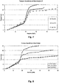
- Figure 8 shows torque and rotation of screw for different flare heights H.
- FIG. 9 shows torque and rotation of screwfor different angles ( ⁇ - ⁇ ) betweenfront of flare and nut. The tested differences were 0, 1, 3 and 5 degrees. In Fig. 9 , the double value is indicated, i.e. 2 ⁇ -2 ⁇ being 0, 2 6 or 10. Yield stress: 310 MPa and flare length: 1 mm
- the radius of the rounded comer of the screw, R s affects the torque as well. It should not be too small, since a sharp comer may increase the chance of initiating cracks for fatigue.
- the preferred radius (R s ) is less than 0,6 mm, preferably less than 0,1 mm.
- Figure 10 shows torque and rotation of screwfor different radii, R s of the rounded corner at the inside of the screw. Yield stress: 380 MPa and flare length: 0.75mm.
- FIG. 13-15 The plastic strain, i.e. the deformation of the flare, for different flare shapes is shown in Figures 13-15 .
- the original shape is indicated by the mesh.
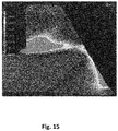
- Figure 13 shows the most preferred flare shape, whereas the effects of using less preferred parameters, which give larger deformations, are shown in Figures 14-15 .
- Figure 13 shows plastic deformation at 14 Nm torque, for a flare of the most preferred flare design.
- the pressure is very large near the top of the flare.
- the amplitude of the pressure at the tip of the flare front portion is largely dependent on the value of ⁇ - ⁇ .
Landscapes
- Engineering & Computer Science (AREA)
- General Engineering & Computer Science (AREA)
- Mechanical Engineering (AREA)
- Transportation (AREA)
- Joints With Pressure Members (AREA)
- Mutual Connection Of Rods And Tubes (AREA)
- Valves And Accessory Devices For Braking Systems (AREA)
Description
- The present invention relates to a brake tube connector and a brake tube connector assembly for use in vehicle braking systems.
- Hydraulic fluid systems are commonly used in automotive vehicle braking systems. Such braking systems comprise several component interfaces that must maintain a relatively high brake fluid hydraulic pressure throughout the service life of the braking system. Any leakage of hydraulic brake fluid is unacceptable. Threaded connectors, such as the one shown in
US2009/0015008 , are commonly used to attach brake tubing to the various braking system components in the manufacture of such braking systems. Such connectors typically include a screw having external threads arranged around a brake tube having a flared tube end that is inserted into a mating threaded hole in a braking system component, to which the tube is to be attached. Brake tubes and components of brake tube connectors are typically made from steel, however, there is a desire to provide brake tubes and connectors of other materials in order to reduce weight and improve corrosion properties. - A further connector is shown in
EP2860433 A1 which discloses a pipe comprising a flare arranged at at least one end of the pipe, the flare extending outwardly from the pipe wall and having an upper surface close to the pipe wall and a lower conical surface below the upper surface. - The present invention aims at solving the above problem by means of a brake tube connector comprising a brake tube having a flare provided at an end thereof, and a screw, wherein the end of the brake tube is rotationally symmetrical around a rotation axis, and the flare comprises a front portion having a front abutment surface, a rear portion having a rear abutment surface, and an intermediate portion arranged between the front portion and the rear portion, and the screw is arranged coaxially with and radially outside the brake tube, and comprises exterior threads and an abutment surface directed towards the rear abutment surface of the flare rear portion. The rear portion of the flare has a frustoconical shape with an inclination angle (γ2), which is the angle between the rear abutment surface and a radial plane, said rear inclination angle (γ2) being 3-25°, preferably 8-17°, and the abutment surface of the screw is inwardly inclined at an inclination angle (γ1), which is in the angle between the screw abutment surface and a radial plane, said angle (γ1) being 3-25°, preferably 8-17°.
- The difference between the rear inclination angle (γ2) of the flare and the inclination angle γ1) of the screw abutment surface is preferably less than ±3°, more preferably less than ±1°, and most preferably ±0,5°. The front portion of the flare preferably has a tapered frustoconical shape having a flare front angle (β), which is the angle between the front abutment surface (6) and a plane parallel to the rotation axis (A).
- Further, the brake tube advantageously consists of an aluminium alloy, preferably an aluminium alloy having a tensile strength of at least 250 MPa, a yield strength of at least 210 MPa, and elongation (A5) of at least 10%. The surface of the front abutment surface of the flare is preferably free from any coating.
- The screw preferably has a rounded corner between an interior surface of the screw and the abutment surface, said rounded corner having a radius (Rs) of less 0,6 mm, preferably less than 0,1 mm. in addition, the brake tube may preferably have a rounded corner between an exterior surface of the tube and the rear abutment surface, said rounded corner having a radius (Rt) of less 0,6 mm, preferably less than 0,1 mm.
- The invention also relates to a brake tube connector assembly, which comprises the above described brake tube connector and a nut, wherein the nut comprises a cylindrical recess having interior threads and a concave frustoconical abutment surface arranged rotation symmetrically to an axial direction of the nut, wherein the nut is adapted to receive the flare of the brake tube and the screw, so that the interior threads of the nut can engage with the exterior threads of the screw, and the front abutment surface of the flare front portion can come into contact with the concave frustoconical abutment surface of the nut.
- The concave frustoconical abutment surface of the nut has a nut angle (α), which is the angle between the concave frustoconical abutment surface (12) and a plane parallel to the rotation axis of the nut, and wherein the difference between the flare front angle (β) of the brake tube flare (2), and the nut angle (α) of the nut (4) preferably is less than ±5°, more preferably less than ±1°, most preferably less than ±0,5°.
- The intermediate portion of the flare has a diameter (d1), and the cylindrical recess of the nut (4) has a diameter (d2), and the difference between the diameter (d2) of the cylindrical recess and the diameter (d1) of the flare is preferably less than 2,5 mm, more preferably less than 0,5 mm. The intermediate portion has a flare length, which is the distance in the axial direction of the brake tube between the front portion and the rear portion, wherein the flare length (B) preferably is 0,3-0,8 mm, more preferably 0,65-0,75 mm.
-
-
Figure 1a is a schematic cross-sectional view of an embodiment of a brake tube connector and a nut, which together form a brake tube connector assembly according to the present application; -
Figure 1b is an enlargement of a portion ofFigure 1a ; -
Figure 2 is a perspective view of the brake tube connector; -
Figure 3 schematically illustrates an experiment set-up to determine friction in threads: -
Figure 4 schematically illustrates an experiment set-up to determine friction between flare and screw; -
Figure 5 is a diagram showing contributions to torque as a function of axial force F on the screw; -
Figure 6 is a diagram showing torque and rotation of a screw for different yield stresses of the tube; -
Figure 7 is a diagram showing torque and rotation of a screw for different lengths of the flare; -
Figure 8 is a diagram showing torque and rotation for different flare heights; -
Figure 9 is a diagram showing torque and rotation for different angles (α-β) between front of flare and nut; -
Figure 10 is a diagram showing torque and rotation for different radii, Rs of the rounded comer at inside of screw; -
Figure 11 is a diagram showing torque and rotation for different flare rear inclination angles; -
Figure 12 is a diagram showing torque and rotation for different differences between flare back angle and screw front angle; -
Figure 13 shows the plastic deformation at 14Nm torque for the most preferred flare design; -
Figure 14 shows plastic deformation at 14 Nm torque for a flare where γ1-γ2=10° and B=0.75 mm; -
Figure 15 shows plastic deformation at 14Nm torque, for a flare where α-β=5° and B=1 mm. - The automotive industry has shown interest in using aluminium tubes for the brake tubing in their cars. One of the challenges related to connectors for brake tubes is the properties and shape of the tube flare where the brake tubings are connected. It is important that the tube flare meets the requirements with respect to the torque that is applied during fastening and refastening and the deformations of the brake tube flare that will occur when the connector is sealed. It has been found that the traditional design of brake tube connectors, such as the one shown in
US2009/0015008 is less suitable when the brake tube and the flare at the end thereof is made of aluminium, since the material strength in the flare end can be reduced due to the increase in stress in the contact area between the rear surface of the flare and the front abutting surface of the screw component, when the brake connector is sealed. - The present brake tube connector aims at providing a configuration for the components included in the connector, which allows the connector to be made of aluminium. It has been found that the design provided by the present invention reduces the risk of material failure in the components and improves the sealing properties of the connector. The present connector design ensures that the fitting will provide highest possible fitting torque resistance/capacity for minimum deformation of the tube flaring. Less deformation ensures that the tube flare fitting properties will remain during several re-work operations.
- The brake tube connector comprises a brake tube and a screw. A brake tube connector assembly is also provided, which comprises a brake tube connector and a nut. The brake tube has a flare provided at an end thereof, which is an integral part of the brake tube and is rotationally symmetrical around a rotation axis (A). The flare comprises a front portion having a front abutment surface, a rear portion having a rear abutment surface, and an intermediate portion arranged between the front portion and the rear portion. The screw is arranged coaxially with and radially outside the brake tube, and comprises exterior threads and an abutment surface directed towards the rear abutment surface of the flare rear portion. The rear portion of the flare has a frustoconical shape with an inclination angle (γ2), which is the angle between the rear abutment surface and a radial plane. The abutment surface of the screw is inwardly inclined at an inclination angle (γ1), which is the angle between the screw abutment surface and a radial plane. The rear inclination angle (γ2) of the flare is 3-25°, preferably 8-17°, and the inclination angle (γ1) of the screw is 3-25°, preferably 8-17°. The inclined abutment surfaces of the flare and the screw reduces the deformation, and thus the stress in the tube material, when torque is applied and the connector is fastened to a nut in a connector assembly.
- Preferably, the difference between the rear inclination angle (γ2) of the flare and the inclination angle (γ1 ) of the screw abutment surface is less than ±3°, preferably less than ±1°, more preferably ±0,5°. By minimising the difference in inclination between the screw abutment surface and the rear abutment surface of the flare, the deformation and stress in the tube material can be further reduced when torque is applied.
- The front portion of the flare preferably has a tapered frustoconical shape having a flare front angle (β), which is the angle between the front abutment surface and a plane parallel to the rotation axis. When the passageway channel of the tube is cylindrical, the plane parallel to the rotation axis is tangential to the inner surface of the tube. By providing a tapered frustoconical front portion, the front abutment surface connects directly to the cylindrical interior surface of the brake tube, without any further intermediate portion at the front of the flare. This allows for improved contact and less deformation of the tube material, when the brake tube connector is assembled with a nut having a recess adapted to receive the flare and the screw.
- The brake tube connector is intended for connection in a brake tube connector assembly, which further comprises a nut. The nut comprises a cylindrical recess having interior threads and a concave frustoconical abutment surface arranged rotation symmetrically to an axial direction of the nut. The abutment surface of the nut is thus tapered, with its narrowest end facing away from the cylindrical recess. The nut is adapted to receive the screw and the flare of the brake tube, so that the interior threads of the nut can engage with the exterior threads of the screw, and the front abutment surface of the flare front portion can come into contact with the abutment surface of the nut. The concave frustoconical abutment surface of the nut has a nut angle (α), which is the angle between the concave frustoconical abutment surface and a plane parallel to the rotation axis of the nut. The difference between the flare front angle (β) of the brake tube flare, and the nut angle (α) of the nut is less than ±5°, preferably less than ±1°, more preferably less than ±0,5°. By minimising the difference in inclination between the nut abutment surface and the front abutment surface of the flare, the deformation and stress in the tube material can be further reduced when torque is applied.
- The radial height of the flare should advantageously be as a large as the nut allows for. The height of the flare is the diameter of the flare outside of the outer diameter of the tube. The widest portion of the flare is in the area of the intermediate portion, which is positioned between the front portion and the rear portion. Thus, the difference between the diameter of the cylindrical recess and the diameter of the intermediate portion of the flare is preferably less than 2,5 mm, preferably less than 0,5 mm. this allows harder tightening of the screw without increased deformation.
- The intermediate portion of the flare has a flare length, which is the distance in the axial direction of the brake tube between the front portion and the rear portion. The flare length should preferably be as small as the axial pull allows for, and is preferably 0,3-0,8 mm, more preferably 0,65-0,75 mm.
- The screw of brake tube connector preferably has a rounded corner between an interior surface of the screw and the abutment surface, having a radius (Rs) of less 0,6 mm, preferably less than 0,1 mm. The brake tube preferably has a rounded corner between an exterior surface of the tube and the rear abutment surface, having a radius (Rt) of less 0,6 mm, preferably less than 0,1 mm.
- Brake tubes have traditionally been made from steel or copper. It is desired to use aluminium due to its low weight and good corrosion resistance. However, aluminium has lower mechanical strength than steel, and has thus hitherto been avoided for use in brake tubes due to the risk of material failure in brake tube connections. The present brake tube connector design allows the brake tube to be made of an aluminium alloy, since it can efficiently seal the brake tube and the screw without severe deformation of the brake tube flare. The aluminium alloy preferably has a tensile strength of at least 250 MPa, a yield strength of at least 210 MPa, and elongation (A5) of at least 10%, in order to avoid local stress to minimise the risk for cracks in the material, which may lead to leakage. The screw and the nut may be made of steel or any other suitable material.
- Further, the surface of the front abutment surface of the flare is preferably free from any coating.
- A suitable aluminium alloy for manufacture of the brake tube is described in
US2014123719 . Such alloy comprises from about 0.7 to about 1.3 wt-% silicon, up to about 0.50 wt-% iron, from about 0.03 to about 0.2 wt-% copper, up to about 0.5 wt-% manganese, from about 0.6 to about 1.2 wt-% magnesium, up to about 0.05 wt-% chromium, up to about 0.2 wt-% zinc, up to about 0.10 wt-% titanium, and the balance consisting essentially of aluminium and incidental elements and impurities. - A schematic view of a brake tube connector is shown in
Figures 1a and 1b . The brake tube connector is shown in a perspective view inFig. 2 .Figure 1 shows schematically a cross-section of an embodiment of the brake tube connector, which comprises a brake tube (1) having a flare (2) provided at an end thereof. The end of the brake tube is rotationally symmetrical around a rotation axis (A), and comprises a front portion (5) having a front abutment surface (6), a rear portion (7) having a rear abutment surface (8), and an intermediate portion (9) arranged between the front portion (5) and the rear portion (7). The rear portion (7) of the flare has a frustoconical shape with an inclination angle (γ2), which is the angle between the rear abutment surface (8) and a radial plane, said rear inclination angle (γ2) being 3-25°, preferably 8-17°. In the shown embodiment, the front portion (5) of the flare has a tapered frustoconical shape having a flare front angle (β), which is the angle between the front abutment surface (6) and a plane parallel to the rotation axis (A). - The brake tube preferably has a rounded corner (17) between an exterior surface (18) of the tube and the rear abutment surface (8), said rounded corner having a radius (Rt) of less 0,6 mm, preferably less than 0,1 mm.
- The brake tube connector also comprises a screw (3), arranged coaxially with and radially outside the brake tube (1), and comprising exterior threads (10). The screw has an abutment surface (11) directed towards the rear abutment surface (8) of the flare rear portion (7). The abutment surface (11) of the screw (3), is inwardly inclined at an inclination angle (γ1), which is in the angle between the screw abutment surface (11) and a radial plane, said angle (γ1) being 3-25°, preferably 8-17°. The difference between the rear inclination angle (γ2) of the flare and the inclination angle γ1) of the screw abutment surface is preferably less than ±3°, more preferably less than ±1°, most preferably ±0,5°.
- The screw preferably has a rounded corner (15) between an interior surface (16) of the screw and the abutment surface (11), said rounded corner having a radius (Rs) of less 0,6 mm, preferably less than 0,1 mm.
-
Figures 1a and 1b also shows the nut, which together with the brake tube connector forms a brake tube connector assembly. The nut (4) comprises a cylindrical recess (13) having interior threads (14) and a concave frustoconical abutment surface (12) arranged rotation symmetrically to an axial direction (A) of the nut. The nut (4) being adapted to receive the flare (2) of the brake tube and the screw (3), so that the interior threads (14) of the nut can engage with the exterior threads (10) of the screw, and the front abutment surface (6) of the flare front portion (5) can come into contact with the concave frustoconical abutment surface (12) of the nut. - The concave frustoconical abutment surface (12) of the nut has a nut angle (α), which is the angle between the concave frustoconical abutment surface (12) and a plane parallel to the rotation axis (A) of the nut. The difference between the flare front angle (β) of the brake tube flare (2), and the nut angle (α) of the nut (4) is preferably less than ±5°, more preferably less than ±1°, most preferably less than ±0,5°.
- The intermediate portion (9) of the brake tube flare has a diameter (d1), and the cylindrical recess (13) of the nut (4) has a diameter (d2), and the difference between these diameters (d2) and (d1) of the flare is preferably less than 2,5 mm, preferably less than 0,5 mm.
- Further, the intermediate portion (9) of the brake tube has a preferably flare length (B), being the distance in the axial direction (A) of the brake tube between the front portion (5) and the rear portion (7), and the flare length (B) is preferably 0,3-0,8 mm, more preferably 0,65-0,75 mm.
- Tests have been performed related to the above described brake tube connector, made from a high strength aluminium having a tensile strength above 250 MPa and a yield strength above 210 MPa. In order to be able to study the properties of the brake tube connector, a numerical model of the brake-line connection has been developed, using the finite element code MSC Marc. The model calculates the forces and deformations of the tube when torque is applied to the screw. The model is made axi-symmetrical due to the complexity of a full 3D model, which means that the threads and the rotation of the screw are accounted for in an approximate manner via pure axial translation of the screw. The translation and axial force acting on the screw can thus be related to the rotation and torque during tightening of the screw.
- The torque consists of three contributions:
- Friction between tube and screw, TF.
- Friction in threads, TT.
- Deformation work of flare, TD.
- TD is the torque that would remain if all friction in threads and between screw and flare were absent. The total torque T that is required to tighten the brake-line can thus be written: T= TF + TT + TD.
- These contributions to the torque depend on the axial force acting on the screw, and the dependencies for the two first contributions were determined by suitable experiments, described in the following section, while the latter contribution is given by:

- The relevant dimensions of the tube, screw and nut were parameterized in the model in order to perform sensitivity studies. Both the elastic and plastic behaviour of the material was considered, using the Mises criteria for yield and a uniformly distributed yield stress.
- The contact surfaces between the tube-screw and tube-mutter were modelled by Coulomb friction. There is no relative rotation between tube and nut, hence the friction in the axial/radial direction here is relatively large. The contact between tube and screw is dominated by a large relative rotation, which gives a relatively small friction in the axial/radial direction.
- The mechanism of fastening of brake-lines occurs in two fairly distinctive stages. The first stage is when the front faces of the flare and the nut, and the back of the flare and the screw, establish contact. If there is a difference between the angles α and β, shown in
Figure 1 , the flare will undergo a bending mode before the two surfaces have gained full contact. This can result in some choking of the inner radius of the tube at the front during this stage, depending on the difference between the angles α and β. The larger the difference is, the more choke. The second stage involves the compression of the flare. During this stage, the flare expands radially and the outer diameter of the flare increases. An inclination of the abutment surface at the front of the screw front (the angle γ1) and small length (B) of the flare reduces the expansion of the flare, since the flare is prevented from 'flowing' outwards and there is a large surface area relative to the volume of the flare. - Two methods were used to measure the thread friction and the friction between screw and flare in order to calculate the torque associated with the tightening of brake-tubes.
- The first experiment involved only the screw and nut as illustrated in
Figure 3 . An axial force F was applied to the screw and nut and the resulting torque TT from rotating the screw was measured for a range of values of F. The specification of the screw and nut and the relation between F and TT is shown inFigure 5 , which shows measured contributions to torque as a function of axialforce F on the screw. The measurements are based on a flare with the following parameters: B=I.5mm, α-β=5°, yield stress=310 and Υ=O. The equations show the relationship between axial force (x)and torque (y). - The second experiment was to determine the friction between the screw and the tube acting on the front of the screw. The set-up is illustrated in
Figure 4 , where all parts are identical to the real brake tube except for the threads, which were removed. The nut was fixed, whereas an axial force F and a torque TF were applied simultaneously to the screw, and were recorded for a range of values of F. - A number of parameters were studied in order to evaluate an optimal shape of the flare and screw, and necessary material properties of the tube. The yield stress of the tube material was calculated, assuming an isotropic distribution throughout the tube. If the material work hardens during deformation, the yield stress will be higher in the flare than in the rest of the tube.
- The results of the sensitivity study are presented in terms of curves for the torque applied to the screw vs. its rotation, and contour plots of the plastic deformation of the flare.
Figure 6 shows torque and rotation of the screw for different yield stresses of the tube. The flare length was B=1 mm and front angle difference: α-β=1°. The first slope from 0 to 20 degrees rotation is related to the bending mode of the flare. The increase in slope from 20 to 25 degrees rotation starts when full contact is obtained between screw/flare and nut/flare. The curves level out from 25 degrees rotation and beyond, where the flare starts to deform and expand radially. - The length of the flare has a significant effect on the torque. A small flare has more area per volume than a large flare, and therefore dominates friction which results in more resistance against deformation.
Figure 7 shows torque and rotation of screw for different flare lengths B. Yield stress: 380 MPa and front angle difference: α-β=1°. - The flare diameter has a significant influence on the torque, and it is important that the maximum height that the nut allows for is utilised. The height (H) is correlated to the diameter d1 of the flare, and is the diameter d1 of the flare minus the outer diameter d3 of the tube, divided by two, i.e. H=(d1-d3)/2.
Figure 8 shows torque and rotation of screw for different flare heights H. - The amount of rotations of the screw increases significantly for increasing values of α-β, i.e. for increasing mismatch between the front of the flare and the nut. These large rotations also result in large deformations of the flare, as shown in
Figures 11 and13 .Figure 9 shows torque and rotation of screwfor different angles (α-β) betweenfront of flare and nut. The tested differences were 0, 1, 3 and 5 degrees. InFig. 9 , the double value is indicated, i.e. 2α-2β being 0, 2 6 or 10. Yield stress: 310 MPa and flare length: 1 mm - The radius of the rounded comer of the screw, Rs , affects the torque as well. It should not be too small, since a sharp comer may increase the chance of initiating cracks for fatigue. The preferred radius (Rs) is less than 0,6 mm, preferably less than 0,1 mm.
Figure 10 shows torque and rotation of screwfor different radii, Rs of the rounded corner at the inside of the screw. Yield stress: 380 MPa and flare length: 0.75mm. - The back angle has a small but positive effect on the torque. The difference is most pronounced for large rotations of the screw. The positive effect is mostly related to the increased resistance of radial expansion of the flare.
Figure 11 shows torque and rotation of the screwfor different flare rear inclination angles, where γ=γ1=γ2. Yield stress: 380 MPa and flare length: 0.75mm. - As for the front angles, the match between the screw front and back of the flare is essential to gain maximum torque for minimum deformation of the flare. If there is a mismatch between these surfaces, there will be large local deformations, and less torque for the same deformations, shown in
Figure 12. Figure 12 shows the torque and rotation of the screw for different differences between flare rear inclination angle and screw front angle γ1-γ2 where the flare rear inclination angle was constant; γ2=10°. - The plastic strain, i.e. the deformation of the flare, for different flare shapes is shown in
Figures 13-15 . The original shape is indicated by the mesh.Figure 13 shows the most preferred flare shape, whereas the effects of using less preferred parameters, which give larger deformations, are shown inFigures 14-15 . -
Figure 13 shows plastic deformation at 14 Nm torque, for a flare of the most preferred flare design.Figure 14 shows plastic deformation at 14 Nm torque for a flare where γ1-γ2=10° and B=0.75 mm. The flare deformation is relatively large due to the mismatch between the screw and the flare.Figure 15 shows plastic deformation at 14Nm torque, for a flare where α-β=5° and B=1 mm. The flare deformation is relatively large due to the bending of the front. - The pressure is very large near the top of the flare. The amplitude of the pressure at the tip of the flare front portion is largely dependent on the value of α-β. For α-β=0, i.e. identical angle of flare and nut, the amplitude is small, whereas a small difference, e.g. α-β =1°, results in a pressure, which may be desirable for sealing purposes.
Claims (11)
- A brake tube connector comprising a brake tube (1) having a flare (2) provided at an end thereof, and a screw (3), whereinthe end of the brake tube has a flare (2), which is rotationally symmetrical around a rotation axis (A), said flare comprising a front portion (5) having a front abutment surface (6), a rear portion (7) having a rear abutment surface (8), and an intermediate portion (9) arranged between the front portion (5) and the rear portion (7), andthe screw (3) is arranged coaxially with and radially outside the brake tube (1), and comprises exterior threads (10) and an abutment surface (11) directed towards the rear abutment surface (8) of the flare rear portion (7), andcharacterised in that the rear portion (7) of the flare has a frustoconical shape with an inclination angle (γ2), which is the angle between the rear abutment surface (8) and a radial plane, said rear inclination angle (γ2) being 3-25°, preferably 8-17°, and the abutment surface (11) of the screw (3), is inwardly inclined at an inclination angle (γ1), which is in the angle between the screw abutment surface (11) and a radial plane, said angle (γ1) being 3-25°, preferably 8-17°.
- The brake tube connector of claim 1, wherein the difference between the rear inclination angle (γ2) of the flare and the inclination angle (γ1 ) of the screw abutment surface is less than ±3°, preferably less than ±1°, more preferably ±0,5°.
- The brake tube connector of claim 1 or 2, wherein the front portion (5) of the flare has a tapered frustoconical shape having a flare front angle (β), which is the angle between the front abutment surface (6) and a plane parallel to the rotation axis (A).
- The brake tube connector of any one of claims 1-3, wherein the brake tube consists of an aluminium alloy, preferably an aluminium alloy having a tensile strength of at least 250 MPa, a yield strength of at least 210 MPa, and elongation of at least 10%.
- The brake tube connector of any one of claims 1-4, wherein the surface of the front abutment surface (6) of the flare is free from any coating.
- The brake tube connector of any one of claims 1-5, wherein the screw has a rounded corner (15) between an interior surface (16) of the screw and the abutment surface (11), said rounded corner having a radius (Rs) of less 0,6 mm, preferably less than 0,1 mm.
- The brake tube connector of any one of claims 1-6, wherein the brake tube has a rounded corner (17) between an exterior surface (18) of the tube and the rear abutment surface (8), said rounded corner having a radius (Rt) of less 0,6 mm, preferably less than 0,1 mm.
- A brake tube connector assembly characterised in that it comprises the brake tube connector of any one of claims 1-5 and a nut (4), wherein the nut (4) comprises a cylindrical recess (13) having interior threads (14) and a concave frustoconical abutment surface (12) arranged rotation symmetrically to an axial direction (A) of the nut, said nut (4) being adapted to receive the flare (2) of the brake tube and the screw (3), so that the interior threads (14) of the nut can engage with the exterior threads (10) of the screw, and the front abutment surface (6) of the flare front portion (5) can come into contact with the concave frustoconical abutment surface (12) of the nut.
- The brake tube connector assembly of claim 8, wherein the concave frustoconical abutment surface (12) of the nut has a nut angle (α), which is the angle between the concave frustoconical abutment surface (12) and a plane parallel to the rotation axis (A) of the nut, and wherein the difference between the flare front angle (β) of the brake tube flare (2), and the nut angle (α) of the nut (4) is less than ±5°, preferably less than ±1°, more preferably less than ±0,5°.
- The brake tube connector assembly of claim 8, wherein the intermediate portion (9) of the flare has a diameter (d1), and the cylindrical recess (13) of the nut (4) has a diameter (d2), wherein the difference between the diameter (d2) of the cylindrical recess and the diameter (d1) of the flare is less than 2,5 mm, preferably less than 0,5 mm.
- The brake tube connector assembly of any one of claims 8-10 wherein the intermediate portion (9) has a flare length (B), which is the distance in the axial direction (A) of the brake tube between the front portion (5) and the rear portion (7), and wherein the flare length (B) is 0,3-0,8 mm, preferably 0,65-0,75 mm.
Applications Claiming Priority (2)
| Application Number | Priority Date | Filing Date | Title |
|---|---|---|---|
| SE1551317A SE1551317A1 (en) | 2015-10-13 | 2015-10-13 | Brake tube connector and brake tube connector assembly |
| PCT/EP2016/074277 WO2017064028A1 (en) | 2015-10-13 | 2016-10-11 | Brake tube connector and brake tube connector assembly |
Publications (2)
| Publication Number | Publication Date |
|---|---|
| EP3362725A1 EP3362725A1 (en) | 2018-08-22 |
| EP3362725B1 true EP3362725B1 (en) | 2020-01-01 |
Family
ID=57124024
Family Applications (1)
| Application Number | Title | Priority Date | Filing Date |
|---|---|---|---|
| EP16779103.7A Active EP3362725B1 (en) | 2015-10-13 | 2016-10-11 | Brake tube connector and brake tube connector assembly |
Country Status (7)
| Country | Link |
|---|---|
| US (1) | US11125362B2 (en) |
| EP (1) | EP3362725B1 (en) |
| JP (1) | JP2018532084A (en) |
| KR (1) | KR102631096B1 (en) |
| CN (1) | CN108351055A (en) |
| SE (1) | SE1551317A1 (en) |
| WO (1) | WO2017064028A1 (en) |
Families Citing this family (8)
| Publication number | Priority date | Publication date | Assignee | Title |
|---|---|---|---|---|
| US10882505B1 (en) * | 2019-09-04 | 2021-01-05 | Chih-Yang Yen | Brake cable with lubricant sealing device |
| JP7421908B2 (en) * | 2019-11-14 | 2024-01-25 | 臼井国際産業株式会社 | Flare joint structure and flare pipe manufacturing method |
| CN113357452A (en) * | 2020-03-05 | 2021-09-07 | 拉斯泰利商业工会(股份)责任有限公司 | Connector for pipes |
| CN111762144A (en) * | 2020-07-13 | 2020-10-13 | 北京汽车集团越野车有限公司 | Integral brake pipeline structure and vehicle |
| US12173814B2 (en) | 2022-03-18 | 2024-12-24 | Martinrea International US Inc. | Female ISO flare union with integrated mating brake ISO F flare port |
| CN115876359B (en) * | 2022-12-28 | 2025-07-22 | 东风商用车有限公司 | Method for optimizing connection reliability of flaring pipe joint |
| WO2025061633A1 (en) * | 2023-09-21 | 2025-03-27 | Danfoss A/S | Tube coupling with clamping effect for the tube and method of mounting a tube coupling |
| CN122029372A (en) * | 2023-09-21 | 2026-05-12 | 丹佛斯有限公司 | Pipe coupling having differently tapered connection ends and method of installing a pipe coupling |
Family Cites Families (28)
| Publication number | Priority date | Publication date | Assignee | Title |
|---|---|---|---|---|
| FR1235078A (en) | 1959-09-09 | 1960-07-01 | Slitting machine for leather, skins or the like | |
| CH526066A (en) * | 1970-12-16 | 1972-07-31 | Guido Juergen Dipl Ing | Pressure line connection with pressure line nipple, counterpart and union nut |
| US5027559A (en) | 1988-05-06 | 1991-07-02 | Camoga S.P.A. | Sharpening unit for leather splitting machines |
| CN2067628U (en) | 1990-05-16 | 1990-12-19 | 大连轻工业学院 | Mechanical sharpener for clothing cutting machine |
| US5529349A (en) * | 1993-08-25 | 1996-06-25 | Itt Corporation | Mounting apparatus with reduced resistance bead seal |
| US6130404A (en) * | 1997-03-03 | 2000-10-10 | Itt Automotive, Inc. | Electro-optical removal of plastic layer bonded to a metal tube |
| JPH11218269A (en) * | 1998-02-02 | 1999-08-10 | Toyota Motor Corp | Flare fittings and surface treatment method |
| JP3307345B2 (en) * | 1998-10-29 | 2002-07-24 | トヨタ自動車株式会社 | Connection structure of tube |
| US6527304B1 (en) * | 2000-02-17 | 2003-03-04 | Ford Global Technologies, Inc. | Brake tube connector |
| CN2493349Y (en) | 2001-08-31 | 2002-05-29 | 东莞威霸清洁器材有限公司 | Polishing machine with adjustable polishing force |
| JP2005214253A (en) * | 2004-01-28 | 2005-08-11 | Sanoh Industrial Co Ltd | Flared end structure of tube |
| US20070003394A1 (en) * | 2005-02-01 | 2007-01-04 | Carey Paul G | Anti-cross threading fastener |
| DE102005047275B4 (en) * | 2005-10-01 | 2018-12-13 | Man Diesel & Turbo Se | Pressure tube with deformed connection head |
| CN100464105C (en) * | 2006-08-22 | 2009-02-25 | 金洲 | Fan-shaped convex ring thin-walled metal pipe and its forming method and special equipment |
| CA2593305C (en) * | 2007-07-11 | 2008-10-14 | Stanislav Ivanovitch Pliassounov | Flared brake tube connector |
| EP2085672B1 (en) * | 2007-10-19 | 2014-05-21 | O.N. Industries CO. LTD. | Connection mechanism between thin-wall stainless steel tube and joint |
| CN101660641A (en) * | 2008-08-27 | 2010-03-03 | 王周城 | Connecting pipe fitting of compression thin-walled pipe |
| EP2360405A1 (en) * | 2010-02-19 | 2011-08-24 | TI Automotive (Heidelberg) GmbH | Tube connection device |
| WO2013111384A1 (en) | 2012-01-23 | 2013-08-01 | 東京オートマック株式会社 | Blade sharpener and grinding machine |
| WO2013150858A1 (en) * | 2012-04-02 | 2013-10-10 | 三菱電機株式会社 | Pipe joint, air conditioner, method for producing connecting pipe, connecting pipe, and connection method |
| EP2679873B1 (en) * | 2012-06-29 | 2017-05-31 | TI Automotive (Heidelberg) GmbH | Connection device comprising a motor vehicle pipe and a connection fitting |
| CN102873597A (en) | 2012-10-07 | 2013-01-16 | 呼长波 | Electric double-sided knife sharpener |
| US20140123719A1 (en) * | 2012-11-08 | 2014-05-08 | Sapa Extrusions, Inc. | Recrystallized 6XXX Aluminum Alloy with Improved Strength and Formability |
| DE102013105300A1 (en) | 2013-05-23 | 2014-11-27 | Voss Fluid Gmbh | pipe connection |
| EP2860433B1 (en) * | 2013-10-14 | 2018-12-12 | Bant Boru Sanayi Ve Ticaret Anonim Sirketi | Flared pipe connection arrangement |
| CN203993388U (en) | 2013-10-30 | 2014-12-10 | 胡锡辉 | A kind of cycle type multiaspect regulable knife sharpener |
| DE202014102663U1 (en) * | 2014-06-06 | 2014-06-24 | Ti Automotive (Heidelberg) Gmbh | Screw element for connecting pipes and pipe connection device with this screw |
| CN104259939B (en) | 2014-09-26 | 2016-04-20 | 重庆市臻憬科技开发有限公司 | A kind of height self compensation whetstone device |
-
2015
- 2015-10-13 SE SE1551317A patent/SE1551317A1/en not_active Application Discontinuation
-
2016
- 2016-10-11 EP EP16779103.7A patent/EP3362725B1/en active Active
- 2016-10-11 KR KR1020187013333A patent/KR102631096B1/en active Active
- 2016-10-11 WO PCT/EP2016/074277 patent/WO2017064028A1/en not_active Ceased
- 2016-10-11 JP JP2018518457A patent/JP2018532084A/en active Pending
- 2016-10-11 US US15/767,848 patent/US11125362B2/en active Active
- 2016-10-11 CN CN201680055974.7A patent/CN108351055A/en active Pending
Non-Patent Citations (1)
| Title |
|---|
| None * |
Also Published As
| Publication number | Publication date |
|---|---|
| SE1551317A1 (en) | 2017-04-14 |
| JP2018532084A (en) | 2018-11-01 |
| US20180313477A1 (en) | 2018-11-01 |
| US11125362B2 (en) | 2021-09-21 |
| EP3362725A1 (en) | 2018-08-22 |
| KR102631096B1 (en) | 2024-01-30 |
| WO2017064028A1 (en) | 2017-04-20 |
| KR20180066201A (en) | 2018-06-18 |
| CN108351055A (en) | 2018-07-31 |
Similar Documents
| Publication | Publication Date | Title |
|---|---|---|
| US11125362B2 (en) | Brake tube connector and brake tube connector assembly | |
| EP0480478A1 (en) | Tube coupling | |
| US4598938A (en) | Coupling device for making a permanent pipe connection | |
| US20110109082A1 (en) | Method and apparatus for cold joining flanges and coupling elements to pipes | |
| CN104620034B (en) | Pipe joint constructs | |
| CN102168776A (en) | Tube connection device | |
| EP0893640A1 (en) | Mounting apparatus with reduced resistance bead seal | |
| US20100207387A1 (en) | Hose fitting | |
| US7533909B2 (en) | Tube connection device | |
| US20140338178A1 (en) | Method and Jaw Assembly for Applying End Fittings or Couplings to a Fluid Hose | |
| US5658025A (en) | Flare-tube assembly | |
| JPWO2017104282A1 (en) | Threaded joints for steel pipes | |
| EA038944B1 (en) | Threaded joint for steel pipe | |
| US9623467B2 (en) | Form rolling method for joint portion of fluid supply pipe and fluid supply pipe | |
| US3338598A (en) | Coupling method and devices for lined pipe | |
| JP5756170B2 (en) | Method and arrangement for placing an aluminum ferrule on a high strength ring of steel wire | |
| EP2258973B1 (en) | Flared end structure of tube | |
| JPH1096489A (en) | Screw joint for oil well pipe excellent in external pressure resistance | |
| CN212247873U (en) | Durable sling anchoring structure | |
| KR20000056211A (en) | Jointing structure of press type pipe joint | |
| CN111051758A (en) | Formed pipe end sections and pipe thread connections for pipes | |
| RU121891U1 (en) | INTEGRAL END FITTINGS OF POLYMERIC REINFORCED HOSE WITH INTERNAL STEEL CHANNEL | |
| KR20160110033A (en) | an assembly system for a flexible joint | |
| IT201600120936A1 (en) | JUNCTION FOR METAL PIPES | |
| KR20100032608A (en) | Fitting for connecting hose |
Legal Events
| Date | Code | Title | Description |
|---|---|---|---|
| STAA | Information on the status of an ep patent application or granted ep patent |
Free format text: STATUS: THE INTERNATIONAL PUBLICATION HAS BEEN MADE |
|
| PUAI | Public reference made under article 153(3) epc to a published international application that has entered the european phase |
Free format text: ORIGINAL CODE: 0009012 |
|
| STAA | Information on the status of an ep patent application or granted ep patent |
Free format text: STATUS: REQUEST FOR EXAMINATION WAS MADE |
|
| 17P | Request for examination filed |
Effective date: 20180410 |
|
| AK | Designated contracting states |
Kind code of ref document: A1 Designated state(s): AL AT BE BG CH CY CZ DE DK EE ES FI FR GB GR HR HU IE IS IT LI LT LU LV MC MK MT NL NO PL PT RO RS SE SI SK SM TR |
|
| AX | Request for extension of the european patent |
Extension state: BA ME |
|
| DAV | Request for validation of the european patent (deleted) | ||
| DAX | Request for extension of the european patent (deleted) | ||
| GRAP | Despatch of communication of intention to grant a patent |
Free format text: ORIGINAL CODE: EPIDOSNIGR1 |
|
| STAA | Information on the status of an ep patent application or granted ep patent |
Free format text: STATUS: GRANT OF PATENT IS INTENDED |
|
| INTG | Intention to grant announced |
Effective date: 20190429 |
|
| GRAJ | Information related to disapproval of communication of intention to grant by the applicant or resumption of examination proceedings by the epo deleted |
Free format text: ORIGINAL CODE: EPIDOSDIGR1 |
|
| STAA | Information on the status of an ep patent application or granted ep patent |
Free format text: STATUS: REQUEST FOR EXAMINATION WAS MADE |
|
| GRAP | Despatch of communication of intention to grant a patent |
Free format text: ORIGINAL CODE: EPIDOSNIGR1 |
|
| STAA | Information on the status of an ep patent application or granted ep patent |
Free format text: STATUS: GRANT OF PATENT IS INTENDED |
|
| INTG | Intention to grant announced |
Effective date: 20190726 |
|
| RAP1 | Party data changed (applicant data changed or rights of an application transferred) |
Owner name: HYDRO EXTRUDED SOLUTIONS AS |
|
| GRAS | Grant fee paid |
Free format text: ORIGINAL CODE: EPIDOSNIGR3 |
|
| GRAA | (expected) grant |
Free format text: ORIGINAL CODE: 0009210 |
|
| STAA | Information on the status of an ep patent application or granted ep patent |
Free format text: STATUS: THE PATENT HAS BEEN GRANTED |
|
| AK | Designated contracting states |
Kind code of ref document: B1 Designated state(s): AL AT BE BG CH CY CZ DE DK EE ES FI FR GB GR HR HU IE IS IT LI LT LU LV MC MK MT NL NO PL PT RO RS SE SI SK SM TR |
|
| REG | Reference to a national code |
Ref country code: GB Ref legal event code: FG4D |
|
| REG | Reference to a national code |
Ref country code: CH Ref legal event code: EP Ref country code: AT Ref legal event code: REF Ref document number: 1220190 Country of ref document: AT Kind code of ref document: T Effective date: 20200115 |
|
| REG | Reference to a national code |
Ref country code: DE Ref legal event code: R096 Ref document number: 602016027404 Country of ref document: DE |
|
| REG | Reference to a national code |
Ref country code: IE Ref legal event code: FG4D |
|
| REG | Reference to a national code |
Ref country code: NL Ref legal event code: MP Effective date: 20200101 |
|
| REG | Reference to a national code |
Ref country code: LT Ref legal event code: MG4D |
|
| PG25 | Lapsed in a contracting state [announced via postgrant information from national office to epo] |
Ref country code: PT Free format text: LAPSE BECAUSE OF FAILURE TO SUBMIT A TRANSLATION OF THE DESCRIPTION OR TO PAY THE FEE WITHIN THE PRESCRIBED TIME-LIMIT Effective date: 20200527 Ref country code: NO Free format text: LAPSE BECAUSE OF FAILURE TO SUBMIT A TRANSLATION OF THE DESCRIPTION OR TO PAY THE FEE WITHIN THE PRESCRIBED TIME-LIMIT Effective date: 20200401 Ref country code: CZ Free format text: LAPSE BECAUSE OF FAILURE TO SUBMIT A TRANSLATION OF THE DESCRIPTION OR TO PAY THE FEE WITHIN THE PRESCRIBED TIME-LIMIT Effective date: 20200101 Ref country code: LT Free format text: LAPSE BECAUSE OF FAILURE TO SUBMIT A TRANSLATION OF THE DESCRIPTION OR TO PAY THE FEE WITHIN THE PRESCRIBED TIME-LIMIT Effective date: 20200101 Ref country code: NL Free format text: LAPSE BECAUSE OF FAILURE TO SUBMIT A TRANSLATION OF THE DESCRIPTION OR TO PAY THE FEE WITHIN THE PRESCRIBED TIME-LIMIT Effective date: 20200101 Ref country code: FI Free format text: LAPSE BECAUSE OF FAILURE TO SUBMIT A TRANSLATION OF THE DESCRIPTION OR TO PAY THE FEE WITHIN THE PRESCRIBED TIME-LIMIT Effective date: 20200101 Ref country code: RS Free format text: LAPSE BECAUSE OF FAILURE TO SUBMIT A TRANSLATION OF THE DESCRIPTION OR TO PAY THE FEE WITHIN THE PRESCRIBED TIME-LIMIT Effective date: 20200101 |
|
| PG25 | Lapsed in a contracting state [announced via postgrant information from national office to epo] |
Ref country code: BG Free format text: LAPSE BECAUSE OF FAILURE TO SUBMIT A TRANSLATION OF THE DESCRIPTION OR TO PAY THE FEE WITHIN THE PRESCRIBED TIME-LIMIT Effective date: 20200401 Ref country code: GR Free format text: LAPSE BECAUSE OF FAILURE TO SUBMIT A TRANSLATION OF THE DESCRIPTION OR TO PAY THE FEE WITHIN THE PRESCRIBED TIME-LIMIT Effective date: 20200402 Ref country code: IS Free format text: LAPSE BECAUSE OF FAILURE TO SUBMIT A TRANSLATION OF THE DESCRIPTION OR TO PAY THE FEE WITHIN THE PRESCRIBED TIME-LIMIT Effective date: 20200501 Ref country code: HR Free format text: LAPSE BECAUSE OF FAILURE TO SUBMIT A TRANSLATION OF THE DESCRIPTION OR TO PAY THE FEE WITHIN THE PRESCRIBED TIME-LIMIT Effective date: 20200101 Ref country code: LV Free format text: LAPSE BECAUSE OF FAILURE TO SUBMIT A TRANSLATION OF THE DESCRIPTION OR TO PAY THE FEE WITHIN THE PRESCRIBED TIME-LIMIT Effective date: 20200101 Ref country code: SE Free format text: LAPSE BECAUSE OF FAILURE TO SUBMIT A TRANSLATION OF THE DESCRIPTION OR TO PAY THE FEE WITHIN THE PRESCRIBED TIME-LIMIT Effective date: 20200101 |
|
| REG | Reference to a national code |
Ref country code: DE Ref legal event code: R097 Ref document number: 602016027404 Country of ref document: DE |
|
| PG25 | Lapsed in a contracting state [announced via postgrant information from national office to epo] |
Ref country code: ES Free format text: LAPSE BECAUSE OF FAILURE TO SUBMIT A TRANSLATION OF THE DESCRIPTION OR TO PAY THE FEE WITHIN THE PRESCRIBED TIME-LIMIT Effective date: 20200101 Ref country code: RO Free format text: LAPSE BECAUSE OF FAILURE TO SUBMIT A TRANSLATION OF THE DESCRIPTION OR TO PAY THE FEE WITHIN THE PRESCRIBED TIME-LIMIT Effective date: 20200101 Ref country code: SK Free format text: LAPSE BECAUSE OF FAILURE TO SUBMIT A TRANSLATION OF THE DESCRIPTION OR TO PAY THE FEE WITHIN THE PRESCRIBED TIME-LIMIT Effective date: 20200101 Ref country code: EE Free format text: LAPSE BECAUSE OF FAILURE TO SUBMIT A TRANSLATION OF THE DESCRIPTION OR TO PAY THE FEE WITHIN THE PRESCRIBED TIME-LIMIT Effective date: 20200101 Ref country code: SM Free format text: LAPSE BECAUSE OF FAILURE TO SUBMIT A TRANSLATION OF THE DESCRIPTION OR TO PAY THE FEE WITHIN THE PRESCRIBED TIME-LIMIT Effective date: 20200101 Ref country code: DK Free format text: LAPSE BECAUSE OF FAILURE TO SUBMIT A TRANSLATION OF THE DESCRIPTION OR TO PAY THE FEE WITHIN THE PRESCRIBED TIME-LIMIT Effective date: 20200101 |
|
| PLBE | No opposition filed within time limit |
Free format text: ORIGINAL CODE: 0009261 |
|
| STAA | Information on the status of an ep patent application or granted ep patent |
Free format text: STATUS: NO OPPOSITION FILED WITHIN TIME LIMIT |
|
| REG | Reference to a national code |
Ref country code: AT Ref legal event code: MK05 Ref document number: 1220190 Country of ref document: AT Kind code of ref document: T Effective date: 20200101 |
|
| 26N | No opposition filed |
Effective date: 20201002 |
|
| PG25 | Lapsed in a contracting state [announced via postgrant information from national office to epo] |
Ref country code: IT Free format text: LAPSE BECAUSE OF FAILURE TO SUBMIT A TRANSLATION OF THE DESCRIPTION OR TO PAY THE FEE WITHIN THE PRESCRIBED TIME-LIMIT Effective date: 20200101 Ref country code: AT Free format text: LAPSE BECAUSE OF FAILURE TO SUBMIT A TRANSLATION OF THE DESCRIPTION OR TO PAY THE FEE WITHIN THE PRESCRIBED TIME-LIMIT Effective date: 20200101 |
|
| PG25 | Lapsed in a contracting state [announced via postgrant information from national office to epo] |
Ref country code: SI Free format text: LAPSE BECAUSE OF FAILURE TO SUBMIT A TRANSLATION OF THE DESCRIPTION OR TO PAY THE FEE WITHIN THE PRESCRIBED TIME-LIMIT Effective date: 20200101 Ref country code: PL Free format text: LAPSE BECAUSE OF FAILURE TO SUBMIT A TRANSLATION OF THE DESCRIPTION OR TO PAY THE FEE WITHIN THE PRESCRIBED TIME-LIMIT Effective date: 20200101 |
|
| REG | Reference to a national code |
Ref country code: CH Ref legal event code: PL |
|
| GBPC | Gb: european patent ceased through non-payment of renewal fee |
Effective date: 20201011 |
|
| PG25 | Lapsed in a contracting state [announced via postgrant information from national office to epo] |
Ref country code: LU Free format text: LAPSE BECAUSE OF NON-PAYMENT OF DUE FEES Effective date: 20201011 Ref country code: MC Free format text: LAPSE BECAUSE OF FAILURE TO SUBMIT A TRANSLATION OF THE DESCRIPTION OR TO PAY THE FEE WITHIN THE PRESCRIBED TIME-LIMIT Effective date: 20200101 |
|
| REG | Reference to a national code |
Ref country code: BE Ref legal event code: MM Effective date: 20201031 |
|
| PG25 | Lapsed in a contracting state [announced via postgrant information from national office to epo] |
Ref country code: FR Free format text: LAPSE BECAUSE OF NON-PAYMENT OF DUE FEES Effective date: 20201031 |
|
| PG25 | Lapsed in a contracting state [announced via postgrant information from national office to epo] |
Ref country code: BE Free format text: LAPSE BECAUSE OF NON-PAYMENT OF DUE FEES Effective date: 20201031 Ref country code: CH Free format text: LAPSE BECAUSE OF NON-PAYMENT OF DUE FEES Effective date: 20201031 Ref country code: LI Free format text: LAPSE BECAUSE OF NON-PAYMENT OF DUE FEES Effective date: 20201031 Ref country code: GB Free format text: LAPSE BECAUSE OF NON-PAYMENT OF DUE FEES Effective date: 20201011 |
|
| PG25 | Lapsed in a contracting state [announced via postgrant information from national office to epo] |
Ref country code: IE Free format text: LAPSE BECAUSE OF NON-PAYMENT OF DUE FEES Effective date: 20201011 |
|
| REG | Reference to a national code |
Ref country code: DE Ref legal event code: R082 Ref document number: 602016027404 Country of ref document: DE |
|
| PG25 | Lapsed in a contracting state [announced via postgrant information from national office to epo] |
Ref country code: TR Free format text: LAPSE BECAUSE OF FAILURE TO SUBMIT A TRANSLATION OF THE DESCRIPTION OR TO PAY THE FEE WITHIN THE PRESCRIBED TIME-LIMIT Effective date: 20200101 Ref country code: MT Free format text: LAPSE BECAUSE OF FAILURE TO SUBMIT A TRANSLATION OF THE DESCRIPTION OR TO PAY THE FEE WITHIN THE PRESCRIBED TIME-LIMIT Effective date: 20200101 Ref country code: CY Free format text: LAPSE BECAUSE OF FAILURE TO SUBMIT A TRANSLATION OF THE DESCRIPTION OR TO PAY THE FEE WITHIN THE PRESCRIBED TIME-LIMIT Effective date: 20200101 |
|
| PG25 | Lapsed in a contracting state [announced via postgrant information from national office to epo] |
Ref country code: MK Free format text: LAPSE BECAUSE OF FAILURE TO SUBMIT A TRANSLATION OF THE DESCRIPTION OR TO PAY THE FEE WITHIN THE PRESCRIBED TIME-LIMIT Effective date: 20200101 Ref country code: AL Free format text: LAPSE BECAUSE OF FAILURE TO SUBMIT A TRANSLATION OF THE DESCRIPTION OR TO PAY THE FEE WITHIN THE PRESCRIBED TIME-LIMIT Effective date: 20200101 |
|
| P01 | Opt-out of the competence of the unified patent court (upc) registered |
Effective date: 20230525 |
|
| PGFP | Annual fee paid to national office [announced via postgrant information from national office to epo] |
Ref country code: DE Payment date: 20250917 Year of fee payment: 10 |