EP3362359B1 - Vorrichtung und verfahren zur steuerung einer abschirmung für privatsphäre in einer flugzeugpassagiersuite - Google Patents
Vorrichtung und verfahren zur steuerung einer abschirmung für privatsphäre in einer flugzeugpassagiersuite Download PDFInfo
- Publication number
- EP3362359B1 EP3362359B1 EP16790479.6A EP16790479A EP3362359B1 EP 3362359 B1 EP3362359 B1 EP 3362359B1 EP 16790479 A EP16790479 A EP 16790479A EP 3362359 B1 EP3362359 B1 EP 3362359B1
- Authority
- EP
- European Patent Office
- Prior art keywords
- screen
- cable
- control apparatus
- magnet
- Prior art date
- Legal status (The legal status is an assumption and is not a legal conclusion. Google has not performed a legal analysis and makes no representation as to the accuracy of the status listed.)
- Active
Links
- 238000000034 method Methods 0.000 title description 3
- 230000037361 pathway Effects 0.000 claims description 2
- 201000009482 yaws Diseases 0.000 description 3
- 241001669573 Galeorhinus galeus Species 0.000 description 1
- 238000013459 approach Methods 0.000 description 1
- 230000000712 assembly Effects 0.000 description 1
- 238000000429 assembly Methods 0.000 description 1
- 230000009286 beneficial effect Effects 0.000 description 1
- 230000008859 change Effects 0.000 description 1
- 230000008878 coupling Effects 0.000 description 1
- 238000010168 coupling process Methods 0.000 description 1
- 238000005859 coupling reaction Methods 0.000 description 1
- 230000007246 mechanism Effects 0.000 description 1
- 238000009423 ventilation Methods 0.000 description 1
Images


Classifications
-
- B—PERFORMING OPERATIONS; TRANSPORTING
- B64—AIRCRAFT; AVIATION; COSMONAUTICS
- B64D—EQUIPMENT FOR FITTING IN OR TO AIRCRAFT; FLIGHT SUITS; PARACHUTES; ARRANGEMENT OR MOUNTING OF POWER PLANTS OR PROPULSION TRANSMISSIONS IN AIRCRAFT
- B64D11/00—Passenger or crew accommodation; Flight-deck installations not otherwise provided for
- B64D11/06—Arrangements of seats, or adaptations or details specially adapted for aircraft seats
- B64D11/0606—Arrangements of seats, or adaptations or details specially adapted for aircraft seats with privacy shells, screens, separators or the like
-
- B—PERFORMING OPERATIONS; TRANSPORTING
- B64—AIRCRAFT; AVIATION; COSMONAUTICS
- B64D—EQUIPMENT FOR FITTING IN OR TO AIRCRAFT; FLIGHT SUITS; PARACHUTES; ARRANGEMENT OR MOUNTING OF POWER PLANTS OR PROPULSION TRANSMISSIONS IN AIRCRAFT
- B64D11/00—Passenger or crew accommodation; Flight-deck installations not otherwise provided for
- B64D11/06—Arrangements of seats, or adaptations or details specially adapted for aircraft seats
- B64D11/0602—Seat modules, i.e. seat systems including furniture separate from the seat itself
- B64D11/0604—Seat modules, i.e. seat systems including furniture separate from the seat itself including a bed, e.g. cocoon type passenger seat modules
Definitions
- the present invention relates generally to a control apparatus for a privacy screen, for example, of the type utilized in an aircraft passenger suite, and more particularly, to a control apparatus including adjustable guides, a magnet arrangement and a cable arrangement for controlling adjustments, tensioning, dampening, and movement of a privacy screen or like structure.
- Premium class passenger cabins are frequently equipped with private suites that include facilities for sitting, reclining, sleeping in a lay flat position, dining and working. These suites are sometimes equipped with a privacy screen or door that permits the ingress/egress screen to be open or closed as required. Because of limited space, a "pocket" type sliding screen may be desirable. With these screens, it is important to provide a mechanism that is robust, reliable, easily maintained and adjusted, and that operates in a smooth manner in keeping with its presence in a premium class area of the aircraft.
- European Patent application EP2783983 discloses a passenger module for a seating array for an aircraft cabin comprises: a pair of end walls generally extending in a first direction connected by at least one side wall generally extending in a second direction which is substantially orthogonal to the first direction, at least one of the walls defining an entrance to the module; at least one door assembly moveable from a stowed position in which the entrance is unobstructed by the door assembly to a deployed position in which the entrance is at least partially obstructed by the door assembly.
- the present invention provides a screen control apparatus according to claim 1.
- the pocket can be located within a wall of an aircraft passenger suite, the pocket having a vertical opening facing across an entrance to the passenger suite.
- the at least one guide roller can include a top roller rotatably mounted proximate a top of the screen and a bottom roller rotatably mounted proximate a bottom of the screen, the top roller arranged to travel along a top guide mounted within the pocket above the screen, and the bottom roller arranged to travel along a bottom guide mounted within the pocket below the screen.
- the at least one guide roller can include a middle roller rotatably mounted proximate a face of the screen, the middle roller arranged to travel along a middle guide mounted within the pocket between the top and bottom guides.
- the at least one guide rail can be an elongate linear member adjustable at one or both ends to adjust at least one of screen position and trajectory.
- the apparatus can include a top cable block securing the cable to the screen proximate a top of the screen, and a bottom cable block securing the cable to the screen proximate a bottom of the screen, the top and bottom cable blocks moveable with the screen.
- the apparatus can include a glide sheet arranged between the stationary magnet and the moveable magnet, the glide sheet having a wear surface controlling a distance between the moveable magnet and the stationary magnet.
- the cable can include an in-line turnbuckle for adjusting cable tension.
- the damper assembly can include a plurality of pulleys around which the cable is routed along a non-linear pathway.
- the stationary magnet can be a female conical-shaped magnet and the moveable magnet can be a male conical-shaped magnet mounted on the cable, and wherein the stationary magnet is mounted in a tubular guide through which the cable passes.
- the screen can be a door, shade, window, or any other rigid or flexible structure adapted to slide between stowed and deployed positions.
- the present invention provides an aircraft passenger suite according to claim 12.
- Embodiments of the invention can include one or more or any combination of the above features and configurations.
- the suite 10 generally includes a screen 22 that, when deployed, closes off access between the interior of the suite 10 and other areas of the cabin, such as the aisles.
- the screen 22 can also be a door, shade, window, or any other rigid or flexible structure capable of moving, for example sliding, between stowed and deployed positions.
- the screen 22 can serve to provide one or more of privacy, shade, ventilation, etc.
- the passenger suite 10 further includes walls 12, 14, 16, 17, and 18, within which is located, variously, an adjustable seat, ottoman, table, entertainment equipment, controls, storage area, etc. These specific items are not, per se, part of the invention and thus are not described further. Examples of such passenger suites are disclosed in applicant's U.S. Patent Nos. 7,578,471 and 8,662,447 .
- the inventive screen control apparatus and method described herein has application for uses other than in transportation modes.
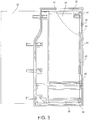
- the suite 10 includes an access opening 20 or entrance between the walls 12 and 18 for passenger and crew ingress and egress.
- the access opening 20 is opened and closed as desired by movement of the screen 22, which slides into the wall 18 to open the access opening 20, as shown in FIG. 1 , and out of the wall 18 to close the access opening 20 and thus close off access to the suite 10, as shown in FIG. 2 .
- FIG. 1 shows the screen 22 in a "stowed” or "open” position
- FIG. 2 shows the screen 22 in a "deployed” or “closed” position.
- a latch 44 operates to hold the screen 22 in the stowed position.
- wall 18 includes an interior "pocket” accessed through a vertically-extending opening.
- the screen 22 is mounted for sliding movement into and out of the pocket through the opening.
- the movement of the screen 22 is guided and controlled by way of a top guide rail 26 and a bottom guide rail 28 on which the respective top and bottom surfaces of the screen 22 ride.
- a middle guide rail 30 positioned between the top guide rail 26 and bottom guide rail 28, for example nearer the bottom rail 28, provides stability and improved motion control to the screen 22.
- Each of the top, bottom and middle guide rails 26, 28, 30 can have a U-shaped cross-section wherein the top guide rail 26 opens downward, the bottom guide rail 28 opens upward, and the middle guide rail 30 opens in a direction of the screen 22.
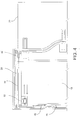
- a damper assembly 32 operates to controls the velocity of a cable 34.
- the damper assembly 32 includes a plurality of pulleys around which the cable 34 is routed along a non-linear path.
- Adjustable cable tensioners 38 and 40 provide tension to the cable 34.
- a magnet system 42 urges the screen 22 to remain in either the stowed or deployed position.
- the crew latch 44 located near the bottom of wall 18 permits a crew member to latch the screen in the stowed position, for example, for taxi, take-off and landing (TTOL).
- FIG. 4 shows a first or "upper" cable block 46 secured near a top of the screen 22.
- the screen 22 pulls the cable block 46 along therewith, thereby pulling the cable 34. Cable velocity is controlled by the damper assembly 32 and the routed cable.
- the cable 34 also moves the attached magnet system 42.
- the cable 34 also moves a second cable block 50 attached to the screen 22, which moves the bottom of the screen 22.
- the cable 34 can be continuous and is generally routed along the top, bottom, and inner sides of the pocket, around a series of vertically oriented pulleys and through the damper assembly 32.
- the cable 34 moves an attached cable magnet carriage 52 on which is mounted a cable magnet 54.
- This assembly glides over a glide sheet 56 that provides a wear surface and controls the distance between the cable magnet 54 and a stationary magnet 58 mounted as part of the magnet system 42.
- the cable magnet 54 can be wedge-shaped to provide linear attraction as the cable magnet 54 approaches the stationary magnet 58. Further details of the magnet system 42 are shown in FIG. 7 .
- a horizontally-oriented top guide roller 60 mounted on the top of the screen 22 rolls within/along the top guide rail 26, a vertically-oriented middle guide roller 62 mounted on a side of the screen 22 rolls within/along the middle guide rail 30, and a horizontally-oriented bottom guide roller 64 rolls within/along the bottom guide rail 28, as shown.
- the roller and guide channel arrangement facilitates and guides smooth horizontal translation of the screen 22.
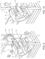
- FIGS. 9 and 10 show the respective "locked” and “unlocked” configurations of the crew latch 44.
- the crew latch 44 can be mounted in the lower corner of the wall 18 away from the vertical opening to the pocket, as shown in FIGS. 1-3 .
- the latch 44 includes a handle 72 rotatably mounted in a latch housing 70.
- a pair of bolts 74, 76 contain respective bolt magnets 78, 80.
- the handle 72 contains handle magnets 82, 84.
- the handle magnets 82, 84 are placed with opposing magnetic poles at 90 degrees to each other. When the handle 72 is rotated, the handle magnets 82, 84 repel or attract the magnets 78, 80, depending on the rotation direction of the handle 72.
- clockwise rotation may repel the magnets 78, 80
- counterclockwise rotation may attract the magnets 78, 80
- Attraction between the handle magnets 82, 84 and bolt magnets 74, 76 pulls the bolts 74, 76 out of a slot 86 formed in the screen 22, thus unlocking the screen 22 and allowing deployment as shown in FIG. 10 .
- the handle magnets 82, 84 repel the bolt magnets 74, 76, thereby pushing the bolts into the slot 86, thus locking the screen 22 in the fully stowed position shown in FIG. 9 .
- top guide rail 26 is adjusted, as shown in FIG. 11 , by way of an adjuster screw 90 positioned near one end of the top guide rail 26, which can be turned by, for example, a hex key or other tool.
- the screw 90 turns to move one end of the guide rail 26 in or out depending on the direction turned.
- Another adjuster screw, not shown, at the other end of the top guide rail 26 performs a similar function. Adjusting only one of the adjuster screws yaws the tope guide rail 26, while adjusting both adjuster screws translates the top guide rail 26.
- a low profile shoulder bolt 92 can be tightened to lock the adjusted position in place.
- Adjustment of the bottom guide rail 28 is shown in FIG. 12 .
- an adjuster screw 94 turns to move one end of the bottom guide rail 28 into a desired position.
- Another adjuster screw, not shown, located at the other end of the bottom guide rail 28 performs a similar function. Again, adjusting only one of the adjuster screws yaws the bottom guide rail 28, while adjusting both adjuster screws translates the bottom guide rail 28.
- a low profile shoulder bolt 96 can be tightened to lock the adjusted position in place.
- Adjustment of the middle guide rail 30 is shown in FIG. 13 .
- an adjuster screw 98 is turned to move one end of the middle guide rail 30 into a desired position.
- Another adjuster screw, not shown, located at the other end of the middle guide rail 30 performs a similar function. Adjusting only one of the adjuster screws yaws the middle guide rail 30, while adjusting both adjuster screws translates the middle guide rail 30. Once the adjustment is made by the screw 98, a low profile shoulder bolt 100 is tightened to lock the adjusted position in place.
- the guide rails 26, 28, 30 can be adjusted individually or together to change the deployment angle, yaw, etc. of the screen 22 to fine-tune horizontal translation and ensure deployment at the correct angle.
- FIG. 14 shows the damper assembly and pulley arrangement thereof including three vertically-oriented pulleys wherein the cable 34 is routed over a first end pulley, under a middle pulley, and over a second end pulley. Details of the magnet system 42 and adjustment of the screen 22 in the stowed and deployed positions are shown in FIG. 16 .
- FIG. 17 illustrates an alternative magnet system 110 utilizing a stationary, female conical magnet 112 and a movable, male conical magnet 114 mounted on a cable 116.
- the stationary magnet 112 is mounted in a tubular guide 118 through which the cable 116 passes.
- the magnet 114 in its unguided, partially guided and fully guided positions, views (1), (2) and (3), not engaging the stationary magnet 112, is not influenced by the stationary magnet 112.
- the magnet 114 moves into the stationary magnet 112, it is increasingly attracted to the stationary magnet 114, view (4), until it is fully engaged with the stationary magnet 114, view (5).
- While the damper system 32 is always limiting the speed of the screen 22, as the screen 22 nears the stowed position, the magnets begin to attract each other, thereby creating a force that moves the screen 22 into the fully stowed position.
- the combination of the force and the damper create an automatic soft close feature.
Landscapes
- Engineering & Computer Science (AREA)
- Aviation & Aerospace Engineering (AREA)
- Operating, Guiding And Securing Of Roll- Type Closing Members (AREA)
- Power-Operated Mechanisms For Wings (AREA)
Claims (12)
- Abschirmungssteuerungsvorrichtung, umfassend:eine Tasche, die zum Verstauen einer Abschirmung (22) darin angepasst ist;eine Abschirmung (22), die zwischen einer Verstauposition innerhalb der Tasche und einer ausgefahrenen Position außerhalb der Tasche beweglich ist;mindestens eine Führungsrolle (60, 62, 64), die auf der Abschirmung (22) getragen wird und angeordnet ist, um sich entlang mindestens einer in der Tasche angebrachten Führungsschiene (26, 28, 30) zu bewegen; undeine Dämpferbaugruppe (32), die in der Tasche angebracht ist und zum Steuern der Drahtseilgeschwindigkeit bedienbar ist,dadurch gekennzeichnet, dass die Abschirmungssteuerungsvorrichtung ferner umfasst ein Drahtseil (34), das um mehrere in der Tasche drehbar angebrachte Seilrollen geführt ist, wobei das Drahtseil (34) an der Abschirmung gesichert ist; undeine Magnetbaugruppe (42, 110), einen feststehenden Magneten (58, 112), der in der Tasche angebracht ist, und einen beweglichen Magneten (54, 114), der auf dem Drahtseil getragen wird, beinhaltend, wobei der bewegliche Magnet (54, 114) in das magnetische Anziehungsfeld des stationären Magneten (58, 112) hinein und wieder heraus beweglich ist, wenn sich die Abschirmung (22) zwischen der Verstauposition und der ausgefahrenen Position bewegt.
- Abschirmungssteuerungsvorrichtung nach Anspruch 1, wobei sich die Tasche innerhalb einer Wand (18) einer Flugzeugpassagiersuite (10) befindet, wobei die Tasche eine vertikale Öffnung aufweist, die quer über einen Eingang (20) zu der Passagiersuite (10) gerichtet ist.
- Abschirmungssteuerungsvorrichtung nach Anspruch 1 oder 2, wobei die mindestens eine Führungsrolle eine obere Rolle (60) umfasst, die in der Nähe einer Oberseite der Abschirmung (22) drehbar angebracht ist, und eine untere Rolle (64), die in der Nähe einer Unterseite der Abschirmung (22) drehbar angebracht ist, wobei die obere Rolle (60) so angeordnet ist, dass sie sich entlang einer oberen Führung (26) bewegt, die innerhalb der Tasche über der Abschirmung (22) angebracht ist, und die untere Rolle (64) so angeordnet ist, dass sie sich entlang einer unteren Führung (28) bewegt, die innerhalb der Tasche unter der Abschirmung (22) angebracht ist.
- Abschirmungssteuerungsvorrichtung nach Anspruch 3, wobei die mindestens eine Führungsrolle ferner eine mittlere Rolle (62) umfasst, die in der Nähe einer Fläche der Abschirmung (22) drehbar angebracht ist, wobei die mittlere Rolle (62) so angeordnet ist, dass sie sich entlang einer mittleren Führung (30), die innerhalb der Tasche zwischen den oberen und unteren Führungen (26, 28) angeordnet ist, bewegen kann.
- Abschirmungssteuerungsvorrichtung nach einem der Ansprüche 1 bis 4, wobei die mindestens eine Führungsschiene (26, 28, 30) ein längliches lineares Teil ist, das an einem oder beiden Enden verstellbar ist, um mindestens eine von der Abschirmungsposition und der Abschirmungsbewegungskurve einzustellen.
- Abschirmungssteuerungsvorrichtung nach einem der Ansprüche 1 bis 5, ferner umfassend einen oberen Drahtseilblock (46), der das Drahtseil (34) an der Abschirmung (22) in der Nähe einer Oberseite der Abschirmung (22) sichert, und einen unteren Drahtseilblock (50), der das Drahtseil (24) an der Abschirmung (22) in der Nähe einer Unterseite der Abschirmung (22) sichert, wobei der obere Drahtseilblock und der untere Drahtseilblock (46, 50) mit der Abschirmung (22) beweglich sind.
- Abschirmungssteuerungsvorrichtung nach einem der Ansprüche 1 bis 6, ferner umfassend ein Gleitblatt (56), das zwischen dem stationären Magneten (58) und dem beweglichen Magneten (52) angeordnet ist, wobei das Gleitblatt eine Verschleißfläche aufweist, die einen Abstand zwischen dem beweglichen Magneten und dem stationären Magneten (58) steuert.
- Abschirmungssteuerungsvorrichtung nach einem der Ansprüche 1 bis 7, wobei das Drahtseil (34) ein lineares Spannschloss zum Einstellen der Drahtseilspannung umfasst.
- Abschirmungssteuerungsvorrichtung nach einem der Ansprüche 1 bis 8, wobei die Dämpferbaugruppe (32) mehrere Seilrollen umfasst, um die das Drahtseil (34) entlang eines nichtlinearen Pfades geführt wird.
- Abschirmungssteuerungsvorrichtung nach einem der Ansprüche 1 bis 9, wobei der stationäre Magnet eine kegelförmige Magnetbuchse (112) ist und der bewegliche Magnet ein kegelförmiger Magnetstecker (114) ist, der an dem Drahtseil (34) angebracht ist, und wobei der stationäre Magnet (112) in einer rohrförmigen Führung (118) angebracht ist, durch die das Drahtseil (34) verläuft.
- Abschirmungssteuerungsvorrichtung nach einem der Ansprüche 1 bis 10, wobei die Abschirmung (22) eine Tür, eine Jalousie, ein Fenster oder eine andere starre oder flexible Konstruktion ist, die zum Gleiten zwischen der Verstauposition und der ausgefahrenen Position geeignet ist.
- Flugzeugpassagiersuite (10), umfassend:mehrere Wände (12, 14, 16, 17, 18);einen Eingang (20), der sich zwischen mit Abstand angeordneten Wänden (12, 18) der mehreren Wände (12, 14, 16, 17, 18) befindet; undeine Abschirmungssteuerungsvorrichtung nach einem der Ansprüche 1 bis 11, wobei sich die Tasche innerhalb einer (18) der mehreren Wände (12, 14, 16, 17, 18) befindet und die Tasche eine vertikale Öffnung aufweist, die quer über den Eingang (20) gerichtet ist.
Applications Claiming Priority (2)
| Application Number | Priority Date | Filing Date | Title |
|---|---|---|---|
| US201562241409P | 2015-10-14 | 2015-10-14 | |
| PCT/US2016/057026 WO2017066559A1 (en) | 2015-10-14 | 2016-10-14 | Aircraft passenger suite privacy screen control apparatus and method |
Publications (2)
| Publication Number | Publication Date |
|---|---|
| EP3362359A1 EP3362359A1 (de) | 2018-08-22 |
| EP3362359B1 true EP3362359B1 (de) | 2019-07-10 |
Family
ID=57223772
Family Applications (1)
| Application Number | Title | Priority Date | Filing Date |
|---|---|---|---|
| EP16790479.6A Active EP3362359B1 (de) | 2015-10-14 | 2016-10-14 | Vorrichtung und verfahren zur steuerung einer abschirmung für privatsphäre in einer flugzeugpassagiersuite |
Country Status (4)
| Country | Link |
|---|---|
| US (1) | US10562633B2 (de) |
| EP (1) | EP3362359B1 (de) |
| CN (1) | CN108290635B (de) |
| WO (1) | WO2017066559A1 (de) |
Families Citing this family (30)
| Publication number | Priority date | Publication date | Assignee | Title |
|---|---|---|---|---|
| WO2016164352A1 (en) * | 2015-04-09 | 2016-10-13 | B/E Aerospace, Inc. | Adjustable sliding screen apparatus |
| GB2548901B (en) * | 2016-04-01 | 2018-07-25 | Thompson Aero Seating Ltd | Aircraft passenger seating with dual-mode privacy door |
| JP7097386B2 (ja) | 2017-04-04 | 2022-07-07 | サフラン シーツ | 2つの座席ユニット間の通路の閉鎖装置 |
| US10421546B2 (en) * | 2017-04-04 | 2019-09-24 | Rockwell Collins, Inc. | Aircraft door and privacy panel assemblies |
| JP7101243B2 (ja) * | 2017-10-03 | 2022-07-14 | シンガポール エアラインズ リミテッド | 航空機用シート |
| US10875650B2 (en) * | 2018-02-01 | 2020-12-29 | The Boeing Company | Room partion assemblies, systems, and methods |
| USD911899S1 (en) * | 2018-05-21 | 2021-03-02 | The Boeing Company | Panel |
| US10899458B2 (en) | 2018-05-21 | 2021-01-26 | The Boeing Company | Sleep systems for aircraft |
| USD895312S1 (en) | 2018-05-21 | 2020-09-08 | The Boeing Company | Lateral sleep apparatus |
| FR3081835B1 (fr) * | 2018-06-05 | 2021-04-09 | Zodiac Seats France | Arrangement de sieges, notamment d'un avion |
| FR3084338B1 (fr) * | 2018-07-27 | 2021-02-12 | Zodiac Seats France | Module double portes pour sieges d'avion |
| DE102018126680A1 (de) * | 2018-10-25 | 2020-04-30 | Recaro Aircraft Seating Gmbh & Co. Kg | Flugzeugsitzvorrichtung |
| US10946966B2 (en) * | 2018-10-29 | 2021-03-16 | B/E Aerospace, Inc. | Multi-panel privacy screen assembly |
| GB2579809B (en) * | 2018-12-14 | 2023-04-12 | Safran Seats Gb Ltd | A kit of parts for assembling an aircraft seat unit |
| FR3089952B1 (fr) * | 2018-12-18 | 2020-11-27 | Safran Seats | Dispositif de fermeture d'un passage entre deux unites de sieges |
| USD916320S1 (en) * | 2019-05-24 | 2021-04-13 | B/E Aerospace, Inc. | Sliding concealment panel |
| GB2588122B (en) * | 2019-10-08 | 2023-11-22 | Safran Seats Gb Ltd | Aircraft passenger accommodation unit |
| US11077947B2 (en) | 2019-11-15 | 2021-08-03 | B/E Aerospace, Inc. | Suite bridge with privacy panel |
| US11299274B1 (en) * | 2020-01-31 | 2022-04-12 | B/E Aerospace, Inc. | Aircraft passenger compartment with an accessibility door |
| IT202000004603A1 (it) * | 2020-03-04 | 2021-09-04 | Optimares S P A | Assieme di sedili per aereo comprendente una parete divisoria mobile. |
| DE102020115567A1 (de) * | 2020-06-12 | 2021-12-16 | Recaro Aircraft Seating Gmbh & Co. Kg | Flugzeugsitzmodul |
| US11691732B2 (en) * | 2020-07-10 | 2023-07-04 | B/E Aerospace, Inc. | Modular multiple-egress doors for dual occupancy aircraft passenger suites |
| GB2605994B (en) * | 2021-04-21 | 2024-02-07 | Thompson Aero Seating Ltd | Door assembly for passenger seating |
| US20220402612A1 (en) * | 2021-06-21 | 2022-12-22 | B/E Aerospace, Inc. | Redundant rail and carriage assembly |
| GB2610387A (en) * | 2021-09-01 | 2023-03-08 | Safran Seats Gb Ltd | Aircraft interior assembly |
| FR3129139A1 (fr) * | 2021-11-17 | 2023-05-19 | Safran Seats | Dispositif de séparation amovible notamment pour une cabine d'avion |
| FR3129917A1 (fr) * | 2021-12-07 | 2023-06-09 | Safran Seats | Cloison pour agencement de siège d’aéronef avec porte coulissante et agencement de siège d’aéronef associé. |
| GB2613629A (en) * | 2021-12-10 | 2023-06-14 | Safran Seats Gb Ltd | Aircraft interior unit with detachable panel |
| US20230365261A1 (en) * | 2022-05-10 | 2023-11-16 | B/E Aerospace, Inc. | Persons with reduced mobility (prm) suite access wall assembly |
| WO2023249671A1 (en) * | 2022-06-22 | 2023-12-28 | Jamco America Inc., Wa | Flexible aircraft privacy door |
Family Cites Families (15)
| Publication number | Priority date | Publication date | Assignee | Title |
|---|---|---|---|---|
| US2653022A (en) * | 1951-07-03 | 1953-09-22 | Armstrong Westropp | Antiinertia mechanism for sliding doors |
| US4063388A (en) * | 1976-11-11 | 1977-12-20 | Roto-Swing, Inc. | Sliding door |
| US4503637A (en) * | 1982-07-06 | 1985-03-12 | Jerry Parente | Sliding door system |
| US5873205A (en) * | 1990-11-28 | 1999-02-23 | Advantage Office Systems, Llc | Privacy panel for use with open office furniture systems |
| US6481160B1 (en) * | 1999-02-04 | 2002-11-19 | The Stanley Works | Axial door operator |
| US7934679B2 (en) * | 2004-02-20 | 2011-05-03 | Singapore Airlines Limited | Aircraft cabin |
| US7188806B2 (en) | 2004-10-22 | 2007-03-13 | B E Aerospace, Inc. | Aircraft passenger accommodation unit with deployable bed |
| EP1996783B1 (de) * | 2006-03-15 | 2012-04-18 | Knorr-Bremse Rail Systems (UK) Limited | Gittertürsystem für bahnsteig |
| CN200992923Y (zh) * | 2006-12-29 | 2007-12-19 | 上海市闸北区中小学科技指导站 | 新型安全地铁屏蔽门 |
| DE102009005905A1 (de) * | 2009-01-23 | 2010-08-12 | Airbus Deutschland Gmbh | Sichtschutz für eine Passagierkabine |
| IT1402815B1 (it) * | 2010-12-03 | 2013-09-27 | Borrtoluzzi Lab S R L | Dispositivo per l'applicazione di porte a scomparsa laterale, particolarmente per mobili |
| US8662447B2 (en) | 2011-06-17 | 2014-03-04 | Be Aerospace, Inc. | Flexible-usage travel suite |
| EP2825458B1 (de) * | 2012-03-14 | 2018-11-28 | B/E Aerospace Inc. | Flugzeugpassagiersuite mit kombinationsbett |
| EP2783983A1 (de) * | 2013-03-28 | 2014-10-01 | Etihad Airways | Fahrgastmodul für eine Sitzanordnung einer Flugzeugkabine |
| EP3019400B1 (de) * | 2013-07-12 | 2017-04-26 | Learjet Inc. | Tür für ein flugzeug |
-
2016
- 2016-10-14 CN CN201680066569.5A patent/CN108290635B/zh active Active
- 2016-10-14 WO PCT/US2016/057026 patent/WO2017066559A1/en active Application Filing
- 2016-10-14 US US15/294,014 patent/US10562633B2/en active Active
- 2016-10-14 EP EP16790479.6A patent/EP3362359B1/de active Active
Non-Patent Citations (1)
| Title |
|---|
| None * |
Also Published As
| Publication number | Publication date |
|---|---|
| US10562633B2 (en) | 2020-02-18 |
| CN108290635B (zh) | 2021-06-15 |
| WO2017066559A1 (en) | 2017-04-20 |
| EP3362359A1 (de) | 2018-08-22 |
| US20170106980A1 (en) | 2017-04-20 |
| CN108290635A (zh) | 2018-07-17 |
Similar Documents
| Publication | Publication Date | Title |
|---|---|---|
| EP3362359B1 (de) | Vorrichtung und verfahren zur steuerung einer abschirmung für privatsphäre in einer flugzeugpassagiersuite | |
| US9920559B2 (en) | Adjustable sliding screen apparatus | |
| EP3647196B1 (de) | Mehrpaneel-sichtschutzanordnung | |
| CA2868186C (en) | Cantilevered tray table and aircraft passenger suite including the same | |
| US7744035B2 (en) | Door for compartment of the baggage-compartment type | |
| EP3313733B1 (de) | Tischanordnung für einen passagiersitz | |
| US11345476B2 (en) | Arrangements for aircraft passenger cabins with privacy divider configurations | |
| US9009918B2 (en) | Adjustable carriage and shifting device | |
| US9102410B2 (en) | Vertically stowed tray table assembly with translational movement | |
| US10414314B2 (en) | Movable table for a motor vehicle | |
| US20150210373A1 (en) | Door assembly for aircraft interior | |
| EP1636087B1 (de) | Verstaubarer tisch für ein fahrzeug | |
| EP2774840B1 (de) | Versenkbare Toilettenschiebetür und Verfahren zu deren Einbau |
Legal Events
| Date | Code | Title | Description |
|---|---|---|---|
| STAA | Information on the status of an ep patent application or granted ep patent |
Free format text: STATUS: UNKNOWN |
|
| STAA | Information on the status of an ep patent application or granted ep patent |
Free format text: STATUS: THE INTERNATIONAL PUBLICATION HAS BEEN MADE |
|
| PUAI | Public reference made under article 153(3) epc to a published international application that has entered the european phase |
Free format text: ORIGINAL CODE: 0009012 |
|
| STAA | Information on the status of an ep patent application or granted ep patent |
Free format text: STATUS: REQUEST FOR EXAMINATION WAS MADE |
|
| 17P | Request for examination filed |
Effective date: 20180511 |
|
| AK | Designated contracting states |
Kind code of ref document: A1 Designated state(s): AL AT BE BG CH CY CZ DE DK EE ES FI FR GB GR HR HU IE IS IT LI LT LU LV MC MK MT NL NO PL PT RO RS SE SI SK SM TR |
|
| AX | Request for extension of the european patent |
Extension state: BA ME |
|
| DAV | Request for validation of the european patent (deleted) | ||
| DAX | Request for extension of the european patent (deleted) | ||
| GRAP | Despatch of communication of intention to grant a patent |
Free format text: ORIGINAL CODE: EPIDOSNIGR1 |
|
| STAA | Information on the status of an ep patent application or granted ep patent |
Free format text: STATUS: GRANT OF PATENT IS INTENDED |
|
| INTG | Intention to grant announced |
Effective date: 20190319 |
|
| GRAS | Grant fee paid |
Free format text: ORIGINAL CODE: EPIDOSNIGR3 |
|
| GRAA | (expected) grant |
Free format text: ORIGINAL CODE: 0009210 |
|
| STAA | Information on the status of an ep patent application or granted ep patent |
Free format text: STATUS: THE PATENT HAS BEEN GRANTED |
|
| AK | Designated contracting states |
Kind code of ref document: B1 Designated state(s): AL AT BE BG CH CY CZ DE DK EE ES FI FR GB GR HR HU IE IS IT LI LT LU LV MC MK MT NL NO PL PT RO RS SE SI SK SM TR |
|
| REG | Reference to a national code |
Ref country code: GB Ref legal event code: FG4D |
|
| REG | Reference to a national code |
Ref country code: CH Ref legal event code: EP Ref country code: AT Ref legal event code: REF Ref document number: 1153322 Country of ref document: AT Kind code of ref document: T Effective date: 20190715 |
|
| REG | Reference to a national code |
Ref country code: NL Ref legal event code: FP |
|
| REG | Reference to a national code |
Ref country code: DE Ref legal event code: R096 Ref document number: 602016016804 Country of ref document: DE |
|
| REG | Reference to a national code |
Ref country code: IE Ref legal event code: FG4D |
|
| REG | Reference to a national code |
Ref country code: LT Ref legal event code: MG4D |
|
| REG | Reference to a national code |
Ref country code: AT Ref legal event code: MK05 Ref document number: 1153322 Country of ref document: AT Kind code of ref document: T Effective date: 20190710 |
|
| PG25 | Lapsed in a contracting state [announced via postgrant information from national office to epo] |
Ref country code: FI Free format text: LAPSE BECAUSE OF FAILURE TO SUBMIT A TRANSLATION OF THE DESCRIPTION OR TO PAY THE FEE WITHIN THE PRESCRIBED TIME-LIMIT Effective date: 20190710 Ref country code: SE Free format text: LAPSE BECAUSE OF FAILURE TO SUBMIT A TRANSLATION OF THE DESCRIPTION OR TO PAY THE FEE WITHIN THE PRESCRIBED TIME-LIMIT Effective date: 20190710 Ref country code: BG Free format text: LAPSE BECAUSE OF FAILURE TO SUBMIT A TRANSLATION OF THE DESCRIPTION OR TO PAY THE FEE WITHIN THE PRESCRIBED TIME-LIMIT Effective date: 20191010 Ref country code: NO Free format text: LAPSE BECAUSE OF FAILURE TO SUBMIT A TRANSLATION OF THE DESCRIPTION OR TO PAY THE FEE WITHIN THE PRESCRIBED TIME-LIMIT Effective date: 20191010 Ref country code: HR Free format text: LAPSE BECAUSE OF FAILURE TO SUBMIT A TRANSLATION OF THE DESCRIPTION OR TO PAY THE FEE WITHIN THE PRESCRIBED TIME-LIMIT Effective date: 20190710 Ref country code: AT Free format text: LAPSE BECAUSE OF FAILURE TO SUBMIT A TRANSLATION OF THE DESCRIPTION OR TO PAY THE FEE WITHIN THE PRESCRIBED TIME-LIMIT Effective date: 20190710 Ref country code: PT Free format text: LAPSE BECAUSE OF FAILURE TO SUBMIT A TRANSLATION OF THE DESCRIPTION OR TO PAY THE FEE WITHIN THE PRESCRIBED TIME-LIMIT Effective date: 20191111 Ref country code: LT Free format text: LAPSE BECAUSE OF FAILURE TO SUBMIT A TRANSLATION OF THE DESCRIPTION OR TO PAY THE FEE WITHIN THE PRESCRIBED TIME-LIMIT Effective date: 20190710 |
|
| PG25 | Lapsed in a contracting state [announced via postgrant information from national office to epo] |
Ref country code: AL Free format text: LAPSE BECAUSE OF FAILURE TO SUBMIT A TRANSLATION OF THE DESCRIPTION OR TO PAY THE FEE WITHIN THE PRESCRIBED TIME-LIMIT Effective date: 20190710 Ref country code: LV Free format text: LAPSE BECAUSE OF FAILURE TO SUBMIT A TRANSLATION OF THE DESCRIPTION OR TO PAY THE FEE WITHIN THE PRESCRIBED TIME-LIMIT Effective date: 20190710 Ref country code: GR Free format text: LAPSE BECAUSE OF FAILURE TO SUBMIT A TRANSLATION OF THE DESCRIPTION OR TO PAY THE FEE WITHIN THE PRESCRIBED TIME-LIMIT Effective date: 20191011 Ref country code: ES Free format text: LAPSE BECAUSE OF FAILURE TO SUBMIT A TRANSLATION OF THE DESCRIPTION OR TO PAY THE FEE WITHIN THE PRESCRIBED TIME-LIMIT Effective date: 20190710 Ref country code: RS Free format text: LAPSE BECAUSE OF FAILURE TO SUBMIT A TRANSLATION OF THE DESCRIPTION OR TO PAY THE FEE WITHIN THE PRESCRIBED TIME-LIMIT Effective date: 20190710 Ref country code: IS Free format text: LAPSE BECAUSE OF FAILURE TO SUBMIT A TRANSLATION OF THE DESCRIPTION OR TO PAY THE FEE WITHIN THE PRESCRIBED TIME-LIMIT Effective date: 20191110 |
|
| PG25 | Lapsed in a contracting state [announced via postgrant information from national office to epo] |
Ref country code: TR Free format text: LAPSE BECAUSE OF FAILURE TO SUBMIT A TRANSLATION OF THE DESCRIPTION OR TO PAY THE FEE WITHIN THE PRESCRIBED TIME-LIMIT Effective date: 20190710 |
|
| PG25 | Lapsed in a contracting state [announced via postgrant information from national office to epo] |
Ref country code: RO Free format text: LAPSE BECAUSE OF FAILURE TO SUBMIT A TRANSLATION OF THE DESCRIPTION OR TO PAY THE FEE WITHIN THE PRESCRIBED TIME-LIMIT Effective date: 20190710 Ref country code: PL Free format text: LAPSE BECAUSE OF FAILURE TO SUBMIT A TRANSLATION OF THE DESCRIPTION OR TO PAY THE FEE WITHIN THE PRESCRIBED TIME-LIMIT Effective date: 20190710 Ref country code: DK Free format text: LAPSE BECAUSE OF FAILURE TO SUBMIT A TRANSLATION OF THE DESCRIPTION OR TO PAY THE FEE WITHIN THE PRESCRIBED TIME-LIMIT Effective date: 20190710 Ref country code: EE Free format text: LAPSE BECAUSE OF FAILURE TO SUBMIT A TRANSLATION OF THE DESCRIPTION OR TO PAY THE FEE WITHIN THE PRESCRIBED TIME-LIMIT Effective date: 20190710 Ref country code: IT Free format text: LAPSE BECAUSE OF FAILURE TO SUBMIT A TRANSLATION OF THE DESCRIPTION OR TO PAY THE FEE WITHIN THE PRESCRIBED TIME-LIMIT Effective date: 20190710 |
|
| PG25 | Lapsed in a contracting state [announced via postgrant information from national office to epo] |
Ref country code: SM Free format text: LAPSE BECAUSE OF FAILURE TO SUBMIT A TRANSLATION OF THE DESCRIPTION OR TO PAY THE FEE WITHIN THE PRESCRIBED TIME-LIMIT Effective date: 20190710 Ref country code: CZ Free format text: LAPSE BECAUSE OF FAILURE TO SUBMIT A TRANSLATION OF THE DESCRIPTION OR TO PAY THE FEE WITHIN THE PRESCRIBED TIME-LIMIT Effective date: 20190710 Ref country code: IS Free format text: LAPSE BECAUSE OF FAILURE TO SUBMIT A TRANSLATION OF THE DESCRIPTION OR TO PAY THE FEE WITHIN THE PRESCRIBED TIME-LIMIT Effective date: 20200224 Ref country code: MC Free format text: LAPSE BECAUSE OF FAILURE TO SUBMIT A TRANSLATION OF THE DESCRIPTION OR TO PAY THE FEE WITHIN THE PRESCRIBED TIME-LIMIT Effective date: 20190710 Ref country code: SK Free format text: LAPSE BECAUSE OF FAILURE TO SUBMIT A TRANSLATION OF THE DESCRIPTION OR TO PAY THE FEE WITHIN THE PRESCRIBED TIME-LIMIT Effective date: 20190710 |
|
| REG | Reference to a national code |
Ref country code: CH Ref legal event code: PL |
|
| REG | Reference to a national code |
Ref country code: DE Ref legal event code: R097 Ref document number: 602016016804 Country of ref document: DE |
|
| PLBE | No opposition filed within time limit |
Free format text: ORIGINAL CODE: 0009261 |
|
| STAA | Information on the status of an ep patent application or granted ep patent |
Free format text: STATUS: NO OPPOSITION FILED WITHIN TIME LIMIT |
|
| PG2D | Information on lapse in contracting state deleted |
Ref country code: IS |
|
| PG25 | Lapsed in a contracting state [announced via postgrant information from national office to epo] |
Ref country code: LU Free format text: LAPSE BECAUSE OF NON-PAYMENT OF DUE FEES Effective date: 20191014 Ref country code: LI Free format text: LAPSE BECAUSE OF NON-PAYMENT OF DUE FEES Effective date: 20191031 Ref country code: CH Free format text: LAPSE BECAUSE OF NON-PAYMENT OF DUE FEES Effective date: 20191031 |
|
| 26N | No opposition filed |
Effective date: 20200603 |
|
| REG | Reference to a national code |
Ref country code: BE Ref legal event code: MM Effective date: 20191031 |
|
| PG25 | Lapsed in a contracting state [announced via postgrant information from national office to epo] |
Ref country code: BE Free format text: LAPSE BECAUSE OF NON-PAYMENT OF DUE FEES Effective date: 20191031 Ref country code: SI Free format text: LAPSE BECAUSE OF FAILURE TO SUBMIT A TRANSLATION OF THE DESCRIPTION OR TO PAY THE FEE WITHIN THE PRESCRIBED TIME-LIMIT Effective date: 20190710 |
|
| PG25 | Lapsed in a contracting state [announced via postgrant information from national office to epo] |
Ref country code: IE Free format text: LAPSE BECAUSE OF NON-PAYMENT OF DUE FEES Effective date: 20191014 |
|
| PG25 | Lapsed in a contracting state [announced via postgrant information from national office to epo] |
Ref country code: CY Free format text: LAPSE BECAUSE OF FAILURE TO SUBMIT A TRANSLATION OF THE DESCRIPTION OR TO PAY THE FEE WITHIN THE PRESCRIBED TIME-LIMIT Effective date: 20190710 |
|
| PG25 | Lapsed in a contracting state [announced via postgrant information from national office to epo] |
Ref country code: HU Free format text: LAPSE BECAUSE OF FAILURE TO SUBMIT A TRANSLATION OF THE DESCRIPTION OR TO PAY THE FEE WITHIN THE PRESCRIBED TIME-LIMIT; INVALID AB INITIO Effective date: 20161014 Ref country code: MT Free format text: LAPSE BECAUSE OF FAILURE TO SUBMIT A TRANSLATION OF THE DESCRIPTION OR TO PAY THE FEE WITHIN THE PRESCRIBED TIME-LIMIT Effective date: 20190710 |
|
| PG25 | Lapsed in a contracting state [announced via postgrant information from national office to epo] |
Ref country code: MK Free format text: LAPSE BECAUSE OF FAILURE TO SUBMIT A TRANSLATION OF THE DESCRIPTION OR TO PAY THE FEE WITHIN THE PRESCRIBED TIME-LIMIT Effective date: 20190710 |
|
| PGFP | Annual fee paid to national office [announced via postgrant information from national office to epo] |
Ref country code: NL Payment date: 20230922 Year of fee payment: 8 Ref country code: GB Payment date: 20230920 Year of fee payment: 8 |
|
| PGFP | Annual fee paid to national office [announced via postgrant information from national office to epo] |
Ref country code: FR Payment date: 20230920 Year of fee payment: 8 |
|
| PGFP | Annual fee paid to national office [announced via postgrant information from national office to epo] |
Ref country code: DE Payment date: 20230920 Year of fee payment: 8 |