EP3362304B1 - Arrangement for the connection of a steering knuckle to a structural element of a motor vehicle - Google Patents
Arrangement for the connection of a steering knuckle to a structural element of a motor vehicle Download PDFInfo
- Publication number
- EP3362304B1 EP3362304B1 EP16790635.3A EP16790635A EP3362304B1 EP 3362304 B1 EP3362304 B1 EP 3362304B1 EP 16790635 A EP16790635 A EP 16790635A EP 3362304 B1 EP3362304 B1 EP 3362304B1
- Authority
- EP
- European Patent Office
- Prior art keywords
- section
- structural element
- axis
- extends
- wheel
- Prior art date
- Legal status (The legal status is an assumption and is not a legal conclusion. Google has not performed a legal analysis and makes no representation as to the accuracy of the status listed.)
- Active
Links
- 230000000295 complement effect Effects 0.000 claims description 3
- 238000001914 filtration Methods 0.000 description 15
- 238000005452 bending Methods 0.000 description 5
- 238000006073 displacement reaction Methods 0.000 description 5
- 238000013016 damping Methods 0.000 description 3
- 230000000694 effects Effects 0.000 description 3
- LYCAIKOWRPUZTN-UHFFFAOYSA-N Ethylene glycol Chemical compound OCCO LYCAIKOWRPUZTN-UHFFFAOYSA-N 0.000 description 2
- 239000003344 environmental pollutant Substances 0.000 description 2
- 239000007788 liquid Substances 0.000 description 2
- 231100000719 pollutant Toxicity 0.000 description 2
- 230000001681 protective effect Effects 0.000 description 2
- 238000010079 rubber tapping Methods 0.000 description 2
- 230000035939 shock Effects 0.000 description 2
- 239000000725 suspension Substances 0.000 description 2
- 238000013519 translation Methods 0.000 description 2
- 230000014616 translation Effects 0.000 description 2
- 230000015572 biosynthetic process Effects 0.000 description 1
- 238000006243 chemical reaction Methods 0.000 description 1
- WGCNASOHLSPBMP-UHFFFAOYSA-N hydroxyacetaldehyde Natural products OCC=O WGCNASOHLSPBMP-UHFFFAOYSA-N 0.000 description 1
- 238000003780 insertion Methods 0.000 description 1
- 230000037431 insertion Effects 0.000 description 1
- 230000003534 oscillatory effect Effects 0.000 description 1
- 230000035515 penetration Effects 0.000 description 1
- 230000003763 resistance to breakage Effects 0.000 description 1
- 230000000284 resting effect Effects 0.000 description 1
- 238000005096 rolling process Methods 0.000 description 1
- 238000009738 saturating Methods 0.000 description 1
- 239000004575 stone Substances 0.000 description 1
Images

Classifications
-
- B—PERFORMING OPERATIONS; TRANSPORTING
- B60—VEHICLES IN GENERAL
- B60G—VEHICLE SUSPENSION ARRANGEMENTS
- B60G21/00—Interconnection systems for two or more resiliently-suspended wheels, e.g. for stabilising a vehicle body with respect to acceleration, deceleration or centrifugal forces
- B60G21/02—Interconnection systems for two or more resiliently-suspended wheels, e.g. for stabilising a vehicle body with respect to acceleration, deceleration or centrifugal forces permanently interconnected
- B60G21/04—Interconnection systems for two or more resiliently-suspended wheels, e.g. for stabilising a vehicle body with respect to acceleration, deceleration or centrifugal forces permanently interconnected mechanically
- B60G21/05—Interconnection systems for two or more resiliently-suspended wheels, e.g. for stabilising a vehicle body with respect to acceleration, deceleration or centrifugal forces permanently interconnected mechanically between wheels on the same axle but on different sides of the vehicle, i.e. the left and right wheel suspensions being interconnected
- B60G21/051—Trailing arm twist beam axles
- B60G21/052—Mounting means therefor
-
- B—PERFORMING OPERATIONS; TRANSPORTING
- B60—VEHICLES IN GENERAL
- B60G—VEHICLE SUSPENSION ARRANGEMENTS
- B60G21/00—Interconnection systems for two or more resiliently-suspended wheels, e.g. for stabilising a vehicle body with respect to acceleration, deceleration or centrifugal forces
- B60G21/02—Interconnection systems for two or more resiliently-suspended wheels, e.g. for stabilising a vehicle body with respect to acceleration, deceleration or centrifugal forces permanently interconnected
- B60G21/04—Interconnection systems for two or more resiliently-suspended wheels, e.g. for stabilising a vehicle body with respect to acceleration, deceleration or centrifugal forces permanently interconnected mechanically
- B60G21/05—Interconnection systems for two or more resiliently-suspended wheels, e.g. for stabilising a vehicle body with respect to acceleration, deceleration or centrifugal forces permanently interconnected mechanically between wheels on the same axle but on different sides of the vehicle, i.e. the left and right wheel suspensions being interconnected
- B60G21/051—Trailing arm twist beam axles
-
- B—PERFORMING OPERATIONS; TRANSPORTING
- B60—VEHICLES IN GENERAL
- B60G—VEHICLE SUSPENSION ARRANGEMENTS
- B60G7/00—Pivoted suspension arms; Accessories thereof
- B60G7/001—Suspension arms, e.g. constructional features
-
- B—PERFORMING OPERATIONS; TRANSPORTING
- B60—VEHICLES IN GENERAL
- B60G—VEHICLE SUSPENSION ARRANGEMENTS
- B60G7/00—Pivoted suspension arms; Accessories thereof
- B60G7/008—Attaching arms to unsprung part of vehicle
-
- B—PERFORMING OPERATIONS; TRANSPORTING
- B62—LAND VEHICLES FOR TRAVELLING OTHERWISE THAN ON RAILS
- B62D—MOTOR VEHICLES; TRAILERS
- B62D7/00—Steering linkage; Stub axles or their mountings
- B62D7/18—Steering knuckles; King pins
-
- B—PERFORMING OPERATIONS; TRANSPORTING
- B60—VEHICLES IN GENERAL
- B60G—VEHICLE SUSPENSION ARRANGEMENTS
- B60G2200/00—Indexing codes relating to suspension types
- B60G2200/40—Indexing codes relating to the wheels in the suspensions
- B60G2200/464—Caster angle
-
- B—PERFORMING OPERATIONS; TRANSPORTING
- B60—VEHICLES IN GENERAL
- B60G—VEHICLE SUSPENSION ARRANGEMENTS
- B60G2204/00—Indexing codes related to suspensions per se or to auxiliary parts
- B60G2204/10—Mounting of suspension elements
- B60G2204/14—Mounting of suspension arms
- B60G2204/148—Mounting of suspension arms on the unsprung part of the vehicle, e.g. wheel knuckle or rigid axle
-
- B—PERFORMING OPERATIONS; TRANSPORTING
- B60—VEHICLES IN GENERAL
- B60G—VEHICLE SUSPENSION ARRANGEMENTS
- B60G2204/00—Indexing codes related to suspensions per se or to auxiliary parts
- B60G2204/40—Auxiliary suspension parts; Adjustment of suspensions
- B60G2204/41—Elastic mounts, e.g. bushings
-
- B—PERFORMING OPERATIONS; TRANSPORTING
- B60—VEHICLES IN GENERAL
- B60G—VEHICLE SUSPENSION ARRANGEMENTS
- B60G2204/00—Indexing codes related to suspensions per se or to auxiliary parts
- B60G2204/40—Auxiliary suspension parts; Adjustment of suspensions
- B60G2204/418—Bearings, e.g. ball or roller bearings
-
- B—PERFORMING OPERATIONS; TRANSPORTING
- B60—VEHICLES IN GENERAL
- B60G—VEHICLE SUSPENSION ARRANGEMENTS
- B60G2204/00—Indexing codes related to suspensions per se or to auxiliary parts
- B60G2204/40—Auxiliary suspension parts; Adjustment of suspensions
- B60G2204/422—Links for mounting suspension elements
- B60G2204/4222—Links for mounting suspension elements for movement on predefined locus of, e.g. the wheel center
-
- B—PERFORMING OPERATIONS; TRANSPORTING
- B60—VEHICLES IN GENERAL
- B60G—VEHICLE SUSPENSION ARRANGEMENTS
- B60G2206/00—Indexing codes related to the manufacturing of suspensions: constructional features, the materials used, procedures or tools
- B60G2206/01—Constructional features of suspension elements, e.g. arms, dampers, springs
- B60G2206/20—Constructional features of semi-rigid axles, e.g. twist beam type axles
-
- B—PERFORMING OPERATIONS; TRANSPORTING
- B60—VEHICLES IN GENERAL
- B60G—VEHICLE SUSPENSION ARRANGEMENTS
- B60G2206/00—Indexing codes related to the manufacturing of suspensions: constructional features, the materials used, procedures or tools
- B60G2206/01—Constructional features of suspension elements, e.g. arms, dampers, springs
- B60G2206/50—Constructional features of wheel supports or knuckles, e.g. steering knuckles, spindle attachments
-
- B—PERFORMING OPERATIONS; TRANSPORTING
- B60—VEHICLES IN GENERAL
- B60G—VEHICLE SUSPENSION ARRANGEMENTS
- B60G2206/00—Indexing codes related to the manufacturing of suspensions: constructional features, the materials used, procedures or tools
- B60G2206/01—Constructional features of suspension elements, e.g. arms, dampers, springs
- B60G2206/80—Manufacturing procedures
- B60G2206/82—Joining
- B60G2206/8207—Joining by screwing
Definitions
- a motor vehicle includes a body, wheels resting on the ground and an axle linking the body to the wheels.
- This axle comprises for each wheel a wheel knuckle on which said wheel is rotatably mounted about a transverse axis having a threaded end, called "wheel rocket”.
- the axle also comprises a substantially longitudinal arm connected to the body by a first end and connecting means of the rocket door at a second end of the arm opposite the first end, and a substantially transverse deformable cross member secured to the respective arms of the two wheels .
- This wheel When the wheel meets an obstacle on the ground, this wheel undergoes a force having a vertical component and a longitudinal component.
- This obstacle may be an irregularity of the ground, a stone, a hole or any other object or formation protruding or recessed from the ground.
- the vertical component is damped by the suspension of the vehicle before being transmitted to the cash register and is therefore little felt by passengers.
- the longitudinal component is not cushioned by the suspension and is felt as a shock by the passengers of the vehicle.
- axle allows longitudinal displacement of the wheel center when the wheel meets an obstacle, so as to improve the comfort of passengers.
- an axle whose kinematics imposes the wheel center, in case of obstacle, a rotational movement about a transverse axis located near the point of contact between the wheel and the ground.
- FR-A-2972389 describes a motor vehicle provided with means for guiding each rocket door in displacement on a longitudinal trajectory.
- the knuckle is pivoted around a transverse axis via a pivot connection. The pivoting movement in both directions is limited and damped by means of a hydroelastic link.
- the hydroelastic linkage has a cylindrical inner armature which is attached to a structural member of the vehicle via a screw.
- the inner frame has a particularly cylindrical shape that extends to a plane and orthogonal face of the structural element.
- the armature comprises a shoulder which allows its plane support against said face of the structural element.
- the invention proposes an arrangement of the type described above, characterized in that the inner armature has a substantially frusto-conical mounting section which extends from a wide end which extends the reach section to a narrow end, the embedding section being received transversely in a complementary housing of the structural element against the inner wall of which the mounting section is clamped transversely by the fixing means.
- FIG. 1 to 4 an arrangement for connecting a wheel to a motor vehicle (not shown).
- This arrangement 10 comprises a wheel knuckle 12 supporting a wheel rocket 14 and two connecting means 16, 18 to a vehicle structure member 20.
- the rocket wheel 14 and the two connecting means 16, 18 are disposed on a same substantially vertical axis "A" perpendicular to the longitudinal axis "L" of the vehicle.
- the arrangement 10 is intended to connect a wheel (not shown) via a wheel hub 22 to a structural element 19 of a motor vehicle.
- the structural element 19 is for example a plate which is fixed to an axle 20 of the vehicle.
- the axle 20 comprises a substantially longitudinal arm 24 connected to the vehicle body (not shown) at one end and to the connecting arrangement 10 at a second end opposite the first end.
- the axle 20 also comprises a deformable transverse cross member 26 integral with the respective arms 24 of two wheels.
- the structural element 19 is more particularly fixed to one of the arms 24.
- the wheel knuckle 12, the wheel rocket 14 and the two connecting means 16, 18 form a single subassembly to be mounted on the vehicle structure member 19.
- the rocket plate could alternatively be part of this subassembly. However, one could consider a mounting of the knuckle directly on the axle.
- the wheel knuckle 12 also includes fins 28 located in the upper part of the wheel knuckle 12 for fixing the brake calipers (not shown).
- the rocket wheel 14, with a transverse axis "B" is a tapered shaft inserted in a bore 30 of the wheel knuckle 12.
- the wheel spindle 14 supports tapered roller bearings 32 of the wheel hub 22 and has a threaded end 34 cooperating with an adjusting nut 36 for adjusting the tapered roller bearing 32.
- the wheel spindle 14 is therefore inserted in the bore 30 of the wheel hub 22 and the wheel (not shown) is thus rotatably mounted on the wheel rocket 14.
- a protective cover 38 may be disposed at one end of the bore 30 of the wheel hub 22 in order to prevent the penetration of pollutants in the bore 30 and in the tapered roller bearing 32.
- a sensor support 40 with axis "B" is arranged on the wheel knuckle 12.
- the sensor support 40 of generally circular shape, comprises a notch 42 intended to cooperate with a sensor 44 for rotating the wheel.
- the wheel knuckle 12 is pivotally mounted on the structural element 19 about a transverse axis "C” via the first connecting means 16.
- the axis "C” of pivoting is parallel to the axis "A" of rotation of the wheel.
- the pivot connection is made by a bearing 46, such as for example a tapered roller bearing supported by a transverse shaft 48 having a threaded end 50.
- the tapered roller bearing 46 comprises an inner ring 52, an outer ring 54 and one or two rows of conical rollers 56 arranged between the rings 52, 54.
- the outer ring 54 is mounted tightly in a bore 58, of axis "C", of the knuckle 12 of wheel, so that the knuckle 12 of wheel rotates around the "C" axis.
- the threaded end 50 of the transverse shaft 48 cooperates with a nut 60 and provides a fastening on the structural element 20.
- a protective cover 62 may be arranged at one end of the bore 58 of the knuckle 12 to prevent pollutants from entering the tapered roller bearing 46.
- the arrangement 10 also comprises a filtering means which limits in both directions the pivoting of the knuckle 12 about its axis "C".
- the filtration means is formed by the second connecting means 18. The filtering means thus allows the rocket carrier 12 to be resiliently returned to an intermediate angular position of rest while filtering the vibrations caused by rolling the wheels on the road.
- the filtration means is formed by a hydroelastic joint 63 of transverse axis "D". It comprises an outer ring 64 of axis "D” transversely offset vertically relative to the axis "C” of pivoting of the knuckle 12.
- the outer ring 64 is mounted tightly in a bore 66 of the knuckle 12. This bore 66 opens transversely vis-à-vis a vertical longitudinal face 68 of the structural element 19, said face 68 proximal, facing the wheel.
- the hydroelastic joint 63 also comprises an inner frame 70 made in one piece.
- the armature has the shape of a shaft extending along the axis "D" transversely coaxial with the axis of the outer ring 64.
- This inner frame 70 extends in part concentrically inside the outer ring 64.
- An annular filter member 72 here a hydroelastic member, is interposed radially between a portion 70A of articulation of the inner frame 70 and the outer ring 64.
- the filter member 72 comprises for example an elastic element and a pocket in which contains a damping liquid and a saturating element.
- the damping liquid is, for example, glycol in order to obtain a sufficient damping effect.
- the filtering means is formed by an elastic articulation.
- the filter member is an elastic member.
- the inner frame 70 having a substantially cylindrical portion 70B of reach which extends at least partially concentrically inside the member 72 of filtration.
- This reach section 70B extends transversely to the proximal face 68 of the structural element 19.
- the reach section 70B has a radial section of substantially constant dimensions. More particularly, this reach section 70B has a substantially cylindrical shape of revolution.
- the span portion 70B thus partially overlaps the articulation portion 70A of the inner frame 70.
- the reach section 70B extends over at least one third of the transverse length of the articulation portion 70A of the inner frame 70.
- the inner frame 70 is pivotable only about the axis "D" transverse to the filter member 72.
- the span portion 70B has more particularly a substantially circular contour section having the largest diameter of the portion 70A of articulation of the inner frame 70.
- the internal armature 70 further has a mounting section 70C which directly extends the reach section 70B transversely to the element 19 structure.
- the recess section 70C has a substantially frustoconical shape which extends from a wide end 74 which is arranged at the end of the reach section 70B to a narrow end 76.
- the wide end 74 of the recess section 70C has a radial section substantially identical to that of the reach section 70B.
- the inner frame 70 does not have a shoulder at the boundary between the embedding section 70C and the reach section 70B.
- This embedding section 70C is received transversely in a housing 78 of complementary shape which is formed in the proximal face 68 of the structural element 19.
- the housing 78 is thus delimited by a wall of frustoconical shape.
- the embedding section 70C is clamped transversely by fixing means against the inner wall of the housing 78. This allows a rigid and very strong fixation of the filtering means 18 on the structural element 19.
- the fastening means are formed by a screw 80 of transverse axis which is screwed into a central transverse tapping 82 of the mounting section 70C which opens into the narrow end 76.
- the threaded rod 84 of the screw 80 is inserted into a through hole 86 which is formed at the bottom of the housing 78 of the structural element 19.
- This orifice 86 is that which is coaxial with the axis "D" of the embedding section of the armature 70.
- the orifice 86 opens into a vertical longitudinal face 88 opposite to the housing 86 of the structural element 19, so-called distal face 88.
- a head 90 of the screw 80 is clamped against the distal face 88 in order to clamp, in reaction, the mounting section 70C against the inner wall of the housing 78.
- the fastening means are formed by a threaded rod which coaxially extends the narrow end of the embedding section.
- This threaded rod is for example made integral with the inner frame or screwed into a central thread.
- the threaded rod is inserted into the hole in the bottom of the housing.
- the threaded rod portion protruding from the distal face of the structural member receives a nut which provides the clamping effect of the embedding section against the inner wall of the housing.
- the filtering means 18 is disposed between the wheel spindle 14 and the first connecting means 16, so as to pivot the wheel knuckle 12 around the transverse axis "C” and to guide it in displacement on a longitudinal curve along arrow F illustrated at figure 1 , substantially in the longitudinal direction "L", in case of presence of an obstacle on the ground. Indeed, when the wheel encounters an obstacle on the ground, this wheel undergoes a force having a longitudinal and vertical component. The longitudinal component, along the "L" axis, applies directly to the wheel rocket 14, and generates a displacement of the wheel. This displacement of the wheel is called “wheel recoil". The wheel recoil, in the event of an obstacle, makes it possible to reduce the forces transmitted to the wheel train of the vehicle.
- the movement of the wheel rocket 14 has an oscillatory movement whose trajectory is an arc following the arrow F , centered on the transverse axis "C" of the filtration means 18.
- the bearing 46 of the pivot link 16 makes it possible to block the translations following all the "L”, “V” and “T” axes, as well as the rotations along the "L” and “V” axes, thus making it possible to adjust the camber wheels.
- Camber is the angle between the wheel and the plane perpendicular to the ground, along the axis "V". Adjusting the camber results in even tire wear.
- the rotation of the wheel knuckle 12 along the axis "C" is authorized by the pivot link 16 but its movement is limited by the filtering means 18, for example of an amplitude of about 10 mm, which allows to master the wheel recoil.
- the inner armature 70 only works in translation along a trajectory orthogonal to the transverse direction "T" with respect to the outer ring 64.
- the inner frame 70 undergoes substantially no pivotal movement relative to the outer ring 64.
- the internal frame 72 absorbs substantially all of the bending force applied by the wheel during an impact.
- the embedding of the inner frame 70 in the housing 78 of the structural element 19 made according to the arrangement of the invention advantageously allows to present a high resistance to breakage due to the shape of the embedding section and the shape of the span section.
- the large diameter of the reach section and the absence of shapes which can promote the concentration of stresses, such as shoulders, at the boundary between these two sections makes it possible to improve the breaking strength of the arrangement.
- the frustoconical shape of the embedding element facilitates the insertion of the embedding section in the housing, while ensuring a large contact surface for the transverse clamping of the inner frame against the housing. This allows in particular to promote a high rigidity of the connection between the inner frame and the structural element.
- the connecting device is easy to implement insofar as it is a pre-assembled subassembly. Such a subassembly is therefore adaptable to all types of axle.
Description
La présente invention concerne le domaine des véhicules automobiles et, notamment les dispositifs de liaison d'une roue à la structure du véhicule. Plus particulièrement, l'invention concerne un agencement pour la liaison d'un porte-fusée à un élément de structure de véhicule automobile comportant :
- un porte-fusée de roue monté pivotant sur l'élément de structure autour d'un premier axe transversal ;
- un moyen de filtration qui limite le pivotement du porte-fusée dans les deux sens et qui comporte :
- une bague extérieure d'axe transversal décalé verticalement par rapport au premier axe, la bague extérieure étant logée dans le porte-fusée en vis-à-vis de l'élément de structure ;
- une armature intérieure s'étendant selon un axe transversal coaxial à l'axe de la bague extérieure,
- un organe annulaire de filtration qui est intercalé radialement entre une portion d'articulation de l'armature intérieure et la bague extérieure ;
- l'armature intérieure comportant un tronçon sensiblement cylindrique de portée qui s'étend au moins en partie concentriquement à l'intérieur de l'organe de filtration et qui s'étend transversalement jusqu'à l'élément de structure en présentant une section radiale de dimensions sensiblement constantes ;
- des moyens de fixation par serrage transversal de l'armature intérieure contre l'élément de structure.
- a wheel knuckle pivotally mounted on the structural member about a first transverse axis;
- filtration means which limits the pivoting of the knuckle carrier in both directions and which comprises:
- an outer ring of transverse axis offset vertically relative to the first axis, the outer ring being housed in the knuckle opposite the structural member;
- an inner armature extending along a transverse axis coaxial with the axis of the outer ring,
- an annular filter member which is interposed radially between a hinge portion of the inner frame and the outer ring;
- the inner armature having a substantially cylindrical bearing section which extends at least partly concentrically inside the filter element and which extends transversely to the structural element having a radial section of substantially constant dimensions;
- fastening means by transverse clamping of the inner armature against the structural element.
Généralement, un véhicule automobile comprend une caisse, des roues reposant sur le sol et un essieu liant la caisse aux roues. Cet essieu comprend pour chaque roue un porte-fusée de roue sur lequel ladite roue est montée à rotation autour d'un axe transversal ayant une extrémité filetée, appelé « fusée de roue ».Generally, a motor vehicle includes a body, wheels resting on the ground and an axle linking the body to the wheels. This axle comprises for each wheel a wheel knuckle on which said wheel is rotatably mounted about a transverse axis having a threaded end, called "wheel rocket".
L'essieu comprend également un bras sensiblement longitudinal lié à la caisse par une première extrémité et des moyens de liaison du porte fusée à une seconde extrémité du bras opposée à la première extrémité, et une traverse déformable sensiblement transversale solidaire des bras respectifs des deux roues.The axle also comprises a substantially longitudinal arm connected to the body by a first end and connecting means of the rocket door at a second end of the arm opposite the first end, and a substantially transverse deformable cross member secured to the respective arms of the two wheels .
Lorsque la roue rencontre un obstacle sur le sol, cette roue subit un effort ayant une composante verticale et une composante longitudinale. Cet obstacle peut être une irrégularité du sol, une pierre, un trou ou tout autre objet ou formation en saillie ou en creux par rapport au sol. La composante verticale est amortie par la suspension du véhicule avant d'être transmise à la caisse et est donc peu ressentie par les passagers. La composante longitudinale n'est en revanche pas amortie par la suspension et est ressentie comme un choc par les passagers du véhicule.When the wheel meets an obstacle on the ground, this wheel undergoes a force having a vertical component and a longitudinal component. This obstacle may be an irregularity of the ground, a stone, a hole or any other object or formation protruding or recessed from the ground. The vertical component is damped by the suspension of the vehicle before being transmitted to the cash register and is therefore little felt by passengers. The longitudinal component, however, is not cushioned by the suspension and is felt as a shock by the passengers of the vehicle.
Il est connu de prévoir que l'essieu permette un déplacement longitudinal du centre de roue lorsque la roue rencontre un obstacle, de façon à améliorer le confort des passagers. Dans ce but, on choisit un essieu dont la cinématique impose au centre de roue, en cas d'obstacle, un mouvement de rotation autour d'un axe transversal situé proche du point de contact entre la roue et le sol. On peut se référer au document
La liaison hydroélastique comporte une armature intérieure cylindrique qui est fixée à un élément de structure du véhicule par l'intermédiaire d'une vis. L'armature intérieure présente plus particulièrement une forme cylindrique qui s'étend jusqu'à une face plane et orthogonale de l'élément de structure. L'armature comporte un épaulement qui permet son appui plan contre ladite face de l'élément de structure.The hydroelastic linkage has a cylindrical inner armature which is attached to a structural member of the vehicle via a screw. The inner frame has a particularly cylindrical shape that extends to a plane and orthogonal face of the structural element. The armature comprises a shoulder which allows its plane support against said face of the structural element.
Cependant, dans ce mode de réalisation, la quasi-totalité des efforts de flexion appliqués à l'armature intérieure transitent par la vis. Or, on a constaté que la vis était susceptible de rompre sous l'effet de certains chocs.However, in this embodiment, almost all of the bending forces applied to the inner armature pass through the screw. However, it was found that the screw was likely to break under the effect of some shocks.
Pour résoudre ce problème, on a proposé d'augmenter le diamètre de la vis. Cependant, il n'est pas possible d'augmenter suffisamment le diamètre de la vis pour résister aux efforts de flexion qui sont susceptibles de lui être appliqués.To solve this problem, it has been proposed to increase the diameter of the screw. However, it is not possible to increase the diameter of the screw sufficiently to withstand the bending forces that may be applied to it.
L'invention propose un agencement du type décrit précédemment, caractérisé en ce que l'armature intérieure présente un tronçon d'encastrement de forme sensiblement tronconique qui s'étend depuis une extrémité large qui prolonge le tronçon de portée jusqu'à une extrémité étroite, le tronçon d'encastrement étant reçu transversalement dans un logement complémentaire de l'élément de structure contre la paroi interne duquel le tronçon d'encastrement est serré transversalement par les moyens de fixation.The invention proposes an arrangement of the type described above, characterized in that the inner armature has a substantially frusto-conical mounting section which extends from a wide end which extends the reach section to a narrow end, the embedding section being received transversely in a complementary housing of the structural element against the inner wall of which the mounting section is clamped transversely by the fixing means.
Selon d'autres caractéristiques de l'invention :
- l'extrémité large du tronçon d'encastrement présente une section radiale sensiblement identique à celle du tronçon de portée ;
- le tronçon de portée présente une section de contour sensiblement circulaire présentant le plus grand diamètre de la portion d'articulation de l'armature intérieure ;
- le tronçon de portée s'étend au moins sur un tiers de la longueur transversale de la portion d'articulation de l'armature intérieure ;
- les moyens de fixation sont formés par une tige filetée qui est reçue dans un orifice traversant qui est réalisé au fond du logement de l'élément de structure et qui est coaxial à l'axe du tronçon d'encastrement ;
- la tige filetée appartient à une vis qui est vissée dans un taraudage transversal central du tronçon d'encastrement qui débouche dans l'extrémité étroite, une tête étant en appui contre une face de l'élément de structure opposée au logement ;
- la tige filetée prolonge coaxialement l'extrémité étroite du tronçon d'encastrement, un écrou étant reçu à l'extrémité libre de la tige filetée et serré en appui contre une face de l'élément de structure opposée au logement ;
- la tige filetée est réalisée en une pièce avec l'armature intérieure.
- the wide end of the embedding section has a radial section substantially identical to that of the span section;
- the span portion has a substantially circular contour section having the largest diameter of the hinge portion of the inner frame;
- the span portion extends at least one third of the transverse length of the hinge portion of the inner frame;
- the fixing means are formed by a threaded rod which is received in a through hole which is formed at the bottom of the housing of the structural element and which is coaxial with the axis of the embedding section;
- the threaded rod belongs to a screw which is screwed into a central transverse tapping of the embedding section which opens into the narrow end, a head bearing against one face of the structural element opposite the housing;
- the threaded rod coaxially extends the narrow end of the embedding section, a nut being received at the free end of the threaded rod and clamped against a face of the structural element opposite the housing;
- the threaded rod is made in one piece with the inner frame.
D'autres caractéristiques et avantages de l'invention apparaitront au cours de la lecture de la description détaillée qui va suivre pour la compréhension de laquelle on se reportera aux dessins annexés dans lesquels :
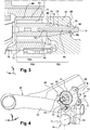
- la
figure 1 est une vue de face d'un dispositif de liaison selon l'invention ; - la
figure 2 est une vue en coupe d'un dispositif de liaison selon lafigure 1 monté entre un moyeu de roue et la structure d'un véhicule automobile ; - la
figure 3 est une vue de détail à plus grande échelle qui représente l'agencement pour la fixation de l'articulation hydroélastique sur un élément de structure du véhicule ; - la
figure 4 est une vue schématique en perspective d'un dispositif de liaison selon lafigure 1 monté sur la structure d'un véhicule.
- the
figure 1 is a front view of a connecting device according to the invention; - the
figure 2 is a sectional view of a connecting device according to thefigure 1 mounted between a wheel hub and the structure of a motor vehicle; - the
figure 3 is a detail view on a larger scale which shows the arrangement for fixing the hydroelastic joint on a structural element of the vehicle; - the
figure 4 is a schematic perspective view of a connection device according to thefigure 1 mounted on the structure of a vehicle.
Dans la suite de la description, des éléments présentant une structure identique ou des fonctions analogues seront désignés par des mêmes références.In the remainder of the description, elements having identical structure or similar functions will be designated by the same references.
Dans la suite de la description, on adoptera à titre non limitatif les orientations suivantes :
- longitudinale, indiquée par la référence "L", et dirigée d'arrière en avant selon le sens de déplacement du véhicule ;
- verticale, indiquée par la référence "V" et orientée de bas en haut selon une direction orthogonale à la route ;
- transversale, indiquée par la référence "T" et orientée de gauche à droite selon l'axe de rotation des roues du véhicules.
- longitudinal, indicated by the reference "L", and directed from rear to front according to the direction of movement of the vehicle;
- vertical, indicated by the reference "V" and oriented from bottom to top in a direction orthogonal to the road;
- crosswise, indicated by the reference "T" and oriented from left to right along the axis of rotation of the wheels of the vehicle.
On a représenté aux
Tel qu'illustré sur la
L'élément 19 de structure est par exemple un plateau qui est fixé à un essieu 20 du véhicule. L'essieu 20 comprend un bras 24 sensiblement longitudinal lié à la caisse du véhicule (non représentée) par une première extrémité et à l'agencement 10 de liaison par une deuxième extrémité, opposée à la première extrémité. L'essieu 20 comporte également une traverse transversale déformable 26 solidaire des bras 24 respectifs de deux roues. L'élément 19 de structure est plus particulièrement fixé à l'un des bras 24.The
Le porte-fusée 12 de roue, la fusée 14 de roue et les deux moyens de liaison 16, 18 forment un unique sous ensemble destiné à être monté sur l'élément 19 de structure du véhicule.The
Le plateau fusée pourrait en variante faire partie de ce sous ensemble. Toutefois, on pourrait envisager une fixation du porte-fusée directement sur l'essieu.The rocket plate could alternatively be part of this subassembly. However, one could consider a mounting of the knuckle directly on the axle.
Le porte-fusée 12 de roue comprend aussi des ailettes 28 situées en partie supérieure du porte-fusée 12 de roue assurant la fixation d'étriers de frein (non représentés).The
La fusée 14 de roue, d'axe transversal "B", est un arbre de forme fuselée, inséré dans un alésage 30 du porte-fusée 12 de roue. La fusée 14 de roue supporte des roulements à rouleaux coniques 32 du moyeu 22 de roue et présente une extrémité filetée 34 coopérant avec un écrou de réglage 36 destiné à régler le roulement à rouleaux coniques 32. La fusée de roue 14 vient donc s'insérer dans l'alésage 30 du moyeu 22 de roue et la roue (non représentée) est ainsi montée à rotation sur la fusée 14 de roue.The
Un capot 38 de protection peut être disposé à une extrémité de l'alésage 30 du moyeu 22 de roue afin d'éviter la pénétration de polluants dans l'alésage 30 et dans le roulement à rouleaux coniques 32.A
Tel qu'illustré sur les
Le porte-fusée 12 de roue est monté pivotant sur l'élément 19 de structure autour d'un axe "C" transversal par l'intermédiaire du premier moyen de liaison 16. L'axe "C" de pivotement est parallèle à l'axe "A" de rotation de la roue. La liaison pivot est réalisée par un roulement 46, tel que par exemple un roulement à rouleaux coniques supporté par un arbre transversal 48 présentant une extrémité filetée 50. Le roulement 46 à rouleaux coniques comprend une bague 52 intérieure, une bague 54 extérieure et une ou deux rangées de rouleaux 56 coniques disposées entre les bagues 52, 54. La bague extérieure 54 est montée serrée dans un alésage 58, d'axe "C", du porte-fusée 12 de roue, de sorte que le porte-fusée 12 de roue pivote autour de l'axe "C". L'extrémité filetée 50 de l'arbre transversal 48 coopère avec un écrou 60 et permet d'assurer une fixation sur l'élément 20 de structure. Un capot 62 de protection peut être disposé à une extrémité de l'alésage 58 du porte-fusée 12 afin d'éviter la pénétration de polluants dans le roulement à rouleaux coniques 46.The
En variante, on pourrait envisager l'utilisation d'un roulement à double rangée de billes.Alternatively, one could consider the use of a double-row ball bearing.
Comme illustré plus en détails à la
Le moyen de filtration est formé par une articulation 63 hydroélastique d'axe transversal "D". Il comporte une bague 64 extérieure d'axe "D" transversal décalé verticalement par rapport à l'axe "C" de pivotement du porte-fusée 12. La bague 64 extérieure est montée serrée dans un alésage 66 du porte-fusée 12. Cet alésage 66 débouche transversalement en vis-à-vis d'une face 68 verticale longitudinale de l'élément 19 de structure, dite face 68 proximale, tournée vers la roue.The filtration means is formed by a hydroelastic joint 63 of transverse axis "D". It comprises an
L'articulation 63 hydroélastique comporte aussi une armature 70 intérieure réalisée en une pièce. L'armature présente la forme d'un arbre s'étendant selon l'axe "D" transversal coaxialement à l'axe de la bague 64 extérieure. Cette armature 70 intérieure s'étend en partie concentriquement à l'intérieur de la bague 64 extérieure.The hydroelastic joint 63 also comprises an
Un organe 72 annulaire de filtration, ici un organe hydroélastique, est intercalé radialement entre une portion 70A d'articulation de l'armature 70 intérieure et la bague 64 extérieure.An
Selon un exemple non limitatif et non représenté, l'organe 72 de filtration comporte par exemple un élément élastique et une poche dans laquelle qui contient un liquide amortisseur et un élément saturateur. Le liquide amortisseur est, par exemple, du glycol afin d'obtenir un effet amortisseur suffisant.According to a nonlimiting example and not shown, the
En variante non représentée de l'invention, le moyen de filtration est formé par une articulation élastique. Dans ce cas, l'organe de filtration est un organe élastique.As a variant not shown of the invention, the filtering means is formed by an elastic articulation. In this case, the filter member is an elastic member.
L'armature 70 intérieure comportant un tronçon 70B sensiblement cylindrique de portée qui s'étend au moins en partie concentriquement à l'intérieur de l'organe 72 de filtration. Ce tronçon 70B de portée s'étend transversalement jusqu'à la face 68 proximale de l'élément 19 de structure. Le tronçon 70B de portée présente une section radiale de dimensions sensiblement constantes. Plus particulièrement, ce tronçon 70B de portée présente une forme sensiblement cylindrique de révolution.The
Le tronçon 70B de portée chevauche ainsi en partie la portion 70A d'articulation de l'armature 70 intérieure. De préférence, le tronçon 70B de portée s'étend sur au moins un tiers de la longueur transversale de la portion 70A d'articulation de l'armature 70 intérieure. Ainsi, l'armature 70 intérieure est susceptible de pivoter uniquement autour de l'axe "D" transversal par rapport à l'organe 72 de filtration.The
Le tronçon 70B de portée présente plus particulièrement une section de contour sensiblement circulaire présentant le plus grand diamètre de la portion 70A d'articulation de l'armature 70 intérieure.The
L'armature 70 interne présente en outre un tronçon 70C d'encastrement qui prolonge directement le tronçon 70B de portée transversalement vers l'élément 19 de structure. Le tronçon 70C d'encastrement présente une forme sensiblement tronconique qui s'étend depuis une extrémité 74 large qui est agencée à l'extrémité du tronçon 70B de portée jusqu'à une extrémité 76 étroite.The
L'extrémité 74 large du tronçon 70C d'encastrement présente une section radiale sensiblement identique à celle du tronçon 70B de portée. De ce fait, l'armature 70 intérieure ne présente pas d'épaulement à la frontière entre le tronçon 70C d'encastrement et le tronçon 70B de portée.The
Ce tronçon 70C d'encastrement est reçu transversalement dans un logement 78 de forme complémentaire qui est réalisé dans la face 68 proximale de l'élément 19 de structure. Le logement 78 est ainsi délimité par une paroi de forme tronconique.This embedding
Le tronçon 70C d'encastrement est serré transversalement par des moyens de fixation contre la paroi interne du logement 78. Ceci permet de réaliser une fixation rigide et très résistante du moyen 18 de filtration sur l'élément 19 de structure.The embedding
Les moyens de fixation sont formés par une vis 80 d'axe transversal qui est vissée dans un taraudage 82 transversal central du tronçon 70C d'encastrement qui débouche dans l'extrémité 76 étroite. La tige 84 filetée de la vis 80 est insérée dans un orifice 86 traversant qui est réalisé au fond du logement 78 de l'élément 19 de structure. Cet orifice 86 est qui est coaxial à l'axe "D" du tronçon d'encastrement de l'armature 70. L'orifice 86 est débouchant dans une face 88 verticale longitudinale opposée au logement 86 de l'élément 19 de structure, dite face 88 distale. Une tête 90 de la vis 80 est serrée contre la face 88 distale afin de serrer, en réaction, le tronçon 70C d'encastrement contre la paroi interne du logement 78.The fastening means are formed by a
En variante non représentée de l'invention, les moyens de fixation sont formés par une tige filetée qui prolonge coaxialement l'extrémité étroite du tronçon d'encastrement. Cette tige filetée est par exemple réalisée venue de matière avec l'armature intérieure ou vissée dans un taraudage central. La tige filetée est insérée dans l'orifice réalisé au fond du logement. La portion de tige filetée dépassant de la face distale de l'élément de structure reçoit un écrou qui procure l'effet de serrage du tronçon d'encastrement contre la paroi interne du logement.In variant not shown of the invention, the fastening means are formed by a threaded rod which coaxially extends the narrow end of the embedding section. This threaded rod is for example made integral with the inner frame or screwed into a central thread. The threaded rod is inserted into the hole in the bottom of the housing. The threaded rod portion protruding from the distal face of the structural member receives a nut which provides the clamping effect of the embedding section against the inner wall of the housing.
Le moyen de filtration 18 est disposé entre la fusée 14 de roue et le premier moyen de liaison 16, de manière à faire pivoter le porte-fusée 12 de roue autour de l'axe transversal "C" et à le guider en déplacement sur une trajectoire courbe longitudinale suivant la flèche F illustrée à la
La rotation du porte-fusée 12 de roue suivant l'axe "C" est autorisée par la liaison pivot 16 mais son débattement est limité par le moyen de filtration 18, par exemple d'une amplitude d'environ 10 mm, ce qui permet de maitriser le recul de roue. De ce fait, l'armature 70 intérieure travaille uniquement en translation selon une trajectoire orthogonale à la direction transversale "T" par rapport à la bague 64 extérieure. L'armature 70 intérieure ne subit sensiblement aucun mouvement de pivotement par rapport à la bague 64 extérieure.The rotation of the
L'armature 72 interne absorbe sensiblement la totalité de l'effort de flexion appliqué par la roue lors d'un choc.The
L'encastrement de l'armature 70 intérieure dans le logement 78 de l'élément de structure 19 réalisé conformément à l'agencement de l'invention permet avantageusement de présenter une grande résistance à la rupture du fait de la forme du tronçon d'encastrement et de la forme du tronçon de portée. Le diamètre important du tronçon de portée et l'absence de formes susceptibles de favoriser la concentration de contraintes, tels que des épaulements, à la frontière entre ces deux tronçons permet d'améliorer la résistance à la rupture de l'agencement.The embedding of the
En outre, la forme tronconique de l'élément d'encastrement permet de faciliter l'insertion du tronçon d'encastrement dans le logement, tout en garantissant une grande surface de contact pour le serrage transversal de l'armature intérieure contre le logement. Ceci permet notamment de favoriser une grande rigidité de la liaison entre l'armature intérieure et l'élément de structure.In addition, the frustoconical shape of the embedding element facilitates the insertion of the embedding section in the housing, while ensuring a large contact surface for the transverse clamping of the inner frame against the housing. This allows in particular to promote a high rigidity of the connection between the inner frame and the structural element.
Ceci permet aussi de garantir un transfert de la majorité des efforts de flexion directement entre l'armature intérieure et l'élément de structure. La tige filetée de la vis est ainsi peu sollicitée en flexion.This also ensures a transfer of the majority of bending forces directly between the inner frame and the structural member. The threaded rod of the screw is thus not stressed in bending.
De plus, le dispositif de liaison est facile à mettre en place dans la mesure où il constitue un sous ensemble monté au préalable. Un tel sous ensemble est de ce fait adaptable à tous les types d'essieu.In addition, the connecting device is easy to implement insofar as it is a pre-assembled subassembly. Such a subassembly is therefore adaptable to all types of axle.
Claims (8)
- Arrangement (10) for the connection of a steering knuckle (12) to a structural element (19) of a motor vehicle, comprising:- a steering knuckle (12) mounted pivotably on the structural element (19) about a first transverse axis (C) ;- a filter means (18) that limits the pivoting of the steering knuckle (12) in the two directions, and which comprises:- an outer ring (64) of transverse axis (D) offset vertically relative to the first axis (C), the outer ring (64) being accommodated in the steering knuckle (12) opposite the structural element (19);- an inner framework (70) extending along a transverse axis (D) coaxial with the axis of the outer ring (64);- an annular filter member (72) that is inserted radially between an articulation section (70A) of the inner framework (70) and the outer ring (64);- the inner framework (70) including a substantially cylindrical bearing section (70B) that extends at least in part concentrically inside the filter member (72) and extends transversely as far as the structural element (19), having a radial cross section of substantially constant dimensions;- means (80) for fastening, by transverse clamping, the inner framework (70) against the structural element (19);
characterized in that the inner framework (70) has a substantially frustoconical embedding section (70C) that extends from a wide end (74) that extends the bearing section (70B) as far as a narrow end (76), the embedding section (70C) being received transversely in a complementary housing (78) of the structural element (19) against the inner wall of which the embedding section (70C) is transversely clamped by the fastening means (80) . - Arrangement according to the preceding claim, characterized in that the wide end (74) of the embedding section has a radial cross section substantially identical to that of the bearing section (70B).
- Arrangement according to either one of the preceding claims, characterized in that the bearing section (70B) has a cross section of substantially circular contour having the largest diameter of the articulation section (70A) of the inner framework (70).
- Arrangement according to any one of the preceding claims, characterized in that the bearing section (70B) extends at least over one third of the transverse length of the articulation section (70A) of the inner framework (70) .
- Arrangement according to any one of the preceding claims, characterized in that the fastening means are formed by a threaded rod (84) that is received in a through-orifice (86) that is made in the bottom of the housing (78) of the structural element (19) and is coaxial to the axis (D) of the embedding section (70C).
- Arrangement according to the preceding claim, characterized in that the threaded rod (84) belongs to a screw (80) that is screwed into a central transverse threading (82) of the embedding section (70C) that opens at the narrow end (76), a head (90) bearing against a face (88) of the structural element (19) opposite the housing.
- Arrangement according to Claim 5, characterized in that the threaded rod coaxially extends the narrow end of the embedding section, a nut being received at the free end of the threaded rod and clamped so as to bear against a face of the structural element opposite the housing.
- Arrangement according to the preceding claim, characterized in that the threaded rod is made as a single component with the inner framework.
Applications Claiming Priority (2)
| Application Number | Priority Date | Filing Date | Title |
|---|---|---|---|
| FR1559799A FR3042442B1 (en) | 2015-10-15 | 2015-10-15 | "ARRANGEMENT FOR CONNECTING A ROCKER TO A MOTOR VEHICLE STRUCTURE ELEMENT" |
| PCT/FR2016/052446 WO2017064382A1 (en) | 2015-10-15 | 2016-09-27 | Arrangement for the connection of a steering knuckle to a structural element of a motor vehicle |
Publications (2)
| Publication Number | Publication Date |
|---|---|
| EP3362304A1 EP3362304A1 (en) | 2018-08-22 |
| EP3362304B1 true EP3362304B1 (en) | 2019-07-10 |
Family
ID=55178141
Family Applications (1)
| Application Number | Title | Priority Date | Filing Date |
|---|---|---|---|
| EP16790635.3A Active EP3362304B1 (en) | 2015-10-15 | 2016-09-27 | Arrangement for the connection of a steering knuckle to a structural element of a motor vehicle |
Country Status (4)
| Country | Link |
|---|---|
| EP (1) | EP3362304B1 (en) |
| KR (1) | KR102550239B1 (en) |
| FR (1) | FR3042442B1 (en) |
| WO (1) | WO2017064382A1 (en) |
Family Cites Families (6)
| Publication number | Priority date | Publication date | Assignee | Title |
|---|---|---|---|---|
| FR2682326B1 (en) * | 1991-10-15 | 1995-06-23 | Peugeot | SUSPENSION, PARTICULARLY WITH PULL ARM FOR A MOTOR VEHICLE, WITH LONGITUDINAL SHOCK ABSORBING SYSTEM. |
| FR2698046B1 (en) * | 1992-11-18 | 1995-01-13 | Maurice Moreau | Independent suspension device for vehicle and vehicle provided with such a device. |
| US6641229B1 (en) * | 2001-10-25 | 2003-11-04 | Hayes Lemmerz International, Inc. | Spindle mounting for aluminum wheel carrier |
| KR100452281B1 (en) * | 2002-06-17 | 2004-10-12 | 현대모비스 주식회사 | Bush for crossmember of suspension |
| ITTO20020553A1 (en) | 2002-06-26 | 2003-12-29 | Fiat Ricerche | OSCILLATING HUB HOLDER |
| FR2972389B1 (en) * | 2011-03-11 | 2013-08-16 | Renault Sa | DEVICE FOR CONNECTING A WHEEL TO A MOTOR VEHICLE STRUCTURE |
-
2015
- 2015-10-15 FR FR1559799A patent/FR3042442B1/en not_active Expired - Fee Related
-
2016
- 2016-09-27 WO PCT/FR2016/052446 patent/WO2017064382A1/en active Application Filing
- 2016-09-27 EP EP16790635.3A patent/EP3362304B1/en active Active
- 2016-09-27 KR KR1020187013664A patent/KR102550239B1/en active IP Right Grant
Non-Patent Citations (1)
| Title |
|---|
| None * |
Also Published As
| Publication number | Publication date |
|---|---|
| KR102550239B1 (en) | 2023-06-30 |
| EP3362304A1 (en) | 2018-08-22 |
| KR20180069033A (en) | 2018-06-22 |
| FR3042442B1 (en) | 2017-11-03 |
| WO2017064382A1 (en) | 2017-04-20 |
| FR3042442A1 (en) | 2017-04-21 |
Similar Documents
| Publication | Publication Date | Title |
|---|---|---|
| EP2683562B1 (en) | Device for connecting a wheel to a motor vehicle structure | |
| EP1765615B1 (en) | Motor vehicle suspension device | |
| EP2099627B1 (en) | Torsionally flexible axle with active control of the steering angle using a hydro-elastic joint | |
| EP1578626B1 (en) | Wheel support device with three pivots, suspension device and vehicle comprising said support device | |
| EP0279135A1 (en) | Front wheel suspension and pivot assembly for a motor vehicle | |
| FR2707926A1 (en) | Improved suspension device for the front wheel of a motor vehicle | |
| EP3362304B1 (en) | Arrangement for the connection of a steering knuckle to a structural element of a motor vehicle | |
| WO2005035284A2 (en) | Motor vehicle steering axle | |
| EP0538116A1 (en) | Suspension particularly with trailing arms for a motor vehicle, with a system for damping longitudinal shocks | |
| FR3018763A1 (en) | REAR STRUCTURE OF MOTOR VEHICLE | |
| WO2012175844A1 (en) | Vehicle suspension arm | |
| WO2021255649A1 (en) | Internal device having an excentric bearing for a steering column | |
| EP3215377B1 (en) | Hub carrier for a twist beam axle | |
| EP3317131B1 (en) | Suspension device for a motor vehicle wheel comprising an arm provided with a sheet-metal body and a solid head attached thereto | |
| FR2750925A1 (en) | Horizontal suspension unit for vehicle wheels | |
| FR3096338A1 (en) | SHOCK ABSORBER FOR MOTOR VEHICLE OR MOTORCYCLE | |
| EP0253708B1 (en) | Rear wheel suspension system with passive action for motor vehicle, and motor vehicle equipped with such suspension system | |
| FR3055878A1 (en) | REAR TRAIN OF A VEHICLE, IN PARTICULAR A MOTOR VEHICLE | |
| EP4134255A1 (en) | Rear end of a motor vehicle, in particular with steering wheels | |
| FR2701236A1 (en) | Trailing arm suspension with filtering-out of longitudinal shocks, particularly for a motor vehicle rear wheel | |
| FR3123594A1 (en) | REAR AXLE FOR MOTOR VEHICLE OF THE TYPE WITH TWO LONGITUDINAL PULLING ARMS WITH IMPROVED ELASTIC BEHAVIOR | |
| FR3013088A1 (en) | DEVICE FOR CONNECTING A WHEEL TO A MOTOR VEHICLE STRUCTURE COMPRISING A BEARING COMPRISING A SOLID LUBRICANT | |
| EP0312425A1 (en) | Trailing arm suspension for the rear wheel of a motor vehicle | |
| FR2682325A1 (en) | Suspension for a motor vehicle front wheel, with system for filtering out longitudinal impacts | |
| FR2710008A1 (en) | Improved front axle assembly for a motor vehicle |
Legal Events
| Date | Code | Title | Description |
|---|---|---|---|
| STAA | Information on the status of an ep patent application or granted ep patent |
Free format text: STATUS: UNKNOWN |
|
| STAA | Information on the status of an ep patent application or granted ep patent |
Free format text: STATUS: THE INTERNATIONAL PUBLICATION HAS BEEN MADE |
|
| PUAI | Public reference made under article 153(3) epc to a published international application that has entered the european phase |
Free format text: ORIGINAL CODE: 0009012 |
|
| STAA | Information on the status of an ep patent application or granted ep patent |
Free format text: STATUS: REQUEST FOR EXAMINATION WAS MADE |
|
| 17P | Request for examination filed |
Effective date: 20180503 |
|
| AK | Designated contracting states |
Kind code of ref document: A1 Designated state(s): AL AT BE BG CH CY CZ DE DK EE ES FI FR GB GR HR HU IE IS IT LI LT LU LV MC MK MT NL NO PL PT RO RS SE SI SK SM TR |
|
| AX | Request for extension of the european patent |
Extension state: BA ME |
|
| DAV | Request for validation of the european patent (deleted) | ||
| DAX | Request for extension of the european patent (deleted) | ||
| GRAP | Despatch of communication of intention to grant a patent |
Free format text: ORIGINAL CODE: EPIDOSNIGR1 |
|
| STAA | Information on the status of an ep patent application or granted ep patent |
Free format text: STATUS: GRANT OF PATENT IS INTENDED |
|
| INTG | Intention to grant announced |
Effective date: 20190208 |
|
| GRAS | Grant fee paid |
Free format text: ORIGINAL CODE: EPIDOSNIGR3 |
|
| GRAA | (expected) grant |
Free format text: ORIGINAL CODE: 0009210 |
|
| STAA | Information on the status of an ep patent application or granted ep patent |
Free format text: STATUS: THE PATENT HAS BEEN GRANTED |
|
| AK | Designated contracting states |
Kind code of ref document: B1 Designated state(s): AL AT BE BG CH CY CZ DE DK EE ES FI FR GB GR HR HU IE IS IT LI LT LU LV MC MK MT NL NO PL PT RO RS SE SI SK SM TR |
|
| REG | Reference to a national code |
Ref country code: GB Ref legal event code: FG4D Free format text: NOT ENGLISH |
|
| REG | Reference to a national code |
Ref country code: CH Ref legal event code: EP Ref country code: AT Ref legal event code: REF Ref document number: 1153164 Country of ref document: AT Kind code of ref document: T Effective date: 20190715 |
|
| REG | Reference to a national code |
Ref country code: DE Ref legal event code: R096 Ref document number: 602016016806 Country of ref document: DE |
|
| REG | Reference to a national code |
Ref country code: IE Ref legal event code: FG4D Free format text: LANGUAGE OF EP DOCUMENT: FRENCH |
|
| REG | Reference to a national code |
Ref country code: NL Ref legal event code: MP Effective date: 20190710 |
|
| REG | Reference to a national code |
Ref country code: LT Ref legal event code: MG4D |
|
| REG | Reference to a national code |
Ref country code: AT Ref legal event code: MK05 Ref document number: 1153164 Country of ref document: AT Kind code of ref document: T Effective date: 20190710 |
|
| PG25 | Lapsed in a contracting state [announced via postgrant information from national office to epo] |
Ref country code: FI Free format text: LAPSE BECAUSE OF FAILURE TO SUBMIT A TRANSLATION OF THE DESCRIPTION OR TO PAY THE FEE WITHIN THE PRESCRIBED TIME-LIMIT Effective date: 20190710 Ref country code: AT Free format text: LAPSE BECAUSE OF FAILURE TO SUBMIT A TRANSLATION OF THE DESCRIPTION OR TO PAY THE FEE WITHIN THE PRESCRIBED TIME-LIMIT Effective date: 20190710 Ref country code: NO Free format text: LAPSE BECAUSE OF FAILURE TO SUBMIT A TRANSLATION OF THE DESCRIPTION OR TO PAY THE FEE WITHIN THE PRESCRIBED TIME-LIMIT Effective date: 20191010 Ref country code: BG Free format text: LAPSE BECAUSE OF FAILURE TO SUBMIT A TRANSLATION OF THE DESCRIPTION OR TO PAY THE FEE WITHIN THE PRESCRIBED TIME-LIMIT Effective date: 20191010 Ref country code: SE Free format text: LAPSE BECAUSE OF FAILURE TO SUBMIT A TRANSLATION OF THE DESCRIPTION OR TO PAY THE FEE WITHIN THE PRESCRIBED TIME-LIMIT Effective date: 20190710 Ref country code: PT Free format text: LAPSE BECAUSE OF FAILURE TO SUBMIT A TRANSLATION OF THE DESCRIPTION OR TO PAY THE FEE WITHIN THE PRESCRIBED TIME-LIMIT Effective date: 20191111 Ref country code: LT Free format text: LAPSE BECAUSE OF FAILURE TO SUBMIT A TRANSLATION OF THE DESCRIPTION OR TO PAY THE FEE WITHIN THE PRESCRIBED TIME-LIMIT Effective date: 20190710 Ref country code: NL Free format text: LAPSE BECAUSE OF FAILURE TO SUBMIT A TRANSLATION OF THE DESCRIPTION OR TO PAY THE FEE WITHIN THE PRESCRIBED TIME-LIMIT Effective date: 20190710 Ref country code: HR Free format text: LAPSE BECAUSE OF FAILURE TO SUBMIT A TRANSLATION OF THE DESCRIPTION OR TO PAY THE FEE WITHIN THE PRESCRIBED TIME-LIMIT Effective date: 20190710 |
|
| PG25 | Lapsed in a contracting state [announced via postgrant information from national office to epo] |
Ref country code: IS Free format text: LAPSE BECAUSE OF FAILURE TO SUBMIT A TRANSLATION OF THE DESCRIPTION OR TO PAY THE FEE WITHIN THE PRESCRIBED TIME-LIMIT Effective date: 20191110 Ref country code: RS Free format text: LAPSE BECAUSE OF FAILURE TO SUBMIT A TRANSLATION OF THE DESCRIPTION OR TO PAY THE FEE WITHIN THE PRESCRIBED TIME-LIMIT Effective date: 20190710 Ref country code: LV Free format text: LAPSE BECAUSE OF FAILURE TO SUBMIT A TRANSLATION OF THE DESCRIPTION OR TO PAY THE FEE WITHIN THE PRESCRIBED TIME-LIMIT Effective date: 20190710 Ref country code: AL Free format text: LAPSE BECAUSE OF FAILURE TO SUBMIT A TRANSLATION OF THE DESCRIPTION OR TO PAY THE FEE WITHIN THE PRESCRIBED TIME-LIMIT Effective date: 20190710 Ref country code: ES Free format text: LAPSE BECAUSE OF FAILURE TO SUBMIT A TRANSLATION OF THE DESCRIPTION OR TO PAY THE FEE WITHIN THE PRESCRIBED TIME-LIMIT Effective date: 20190710 Ref country code: GR Free format text: LAPSE BECAUSE OF FAILURE TO SUBMIT A TRANSLATION OF THE DESCRIPTION OR TO PAY THE FEE WITHIN THE PRESCRIBED TIME-LIMIT Effective date: 20191011 |
|
| PG25 | Lapsed in a contracting state [announced via postgrant information from national office to epo] |
Ref country code: TR Free format text: LAPSE BECAUSE OF FAILURE TO SUBMIT A TRANSLATION OF THE DESCRIPTION OR TO PAY THE FEE WITHIN THE PRESCRIBED TIME-LIMIT Effective date: 20190710 |
|
| PG25 | Lapsed in a contracting state [announced via postgrant information from national office to epo] |
Ref country code: EE Free format text: LAPSE BECAUSE OF FAILURE TO SUBMIT A TRANSLATION OF THE DESCRIPTION OR TO PAY THE FEE WITHIN THE PRESCRIBED TIME-LIMIT Effective date: 20190710 Ref country code: PL Free format text: LAPSE BECAUSE OF FAILURE TO SUBMIT A TRANSLATION OF THE DESCRIPTION OR TO PAY THE FEE WITHIN THE PRESCRIBED TIME-LIMIT Effective date: 20190710 Ref country code: DK Free format text: LAPSE BECAUSE OF FAILURE TO SUBMIT A TRANSLATION OF THE DESCRIPTION OR TO PAY THE FEE WITHIN THE PRESCRIBED TIME-LIMIT Effective date: 20190710 Ref country code: RO Free format text: LAPSE BECAUSE OF FAILURE TO SUBMIT A TRANSLATION OF THE DESCRIPTION OR TO PAY THE FEE WITHIN THE PRESCRIBED TIME-LIMIT Effective date: 20190710 Ref country code: IT Free format text: LAPSE BECAUSE OF FAILURE TO SUBMIT A TRANSLATION OF THE DESCRIPTION OR TO PAY THE FEE WITHIN THE PRESCRIBED TIME-LIMIT Effective date: 20190710 |
|
| PG25 | Lapsed in a contracting state [announced via postgrant information from national office to epo] |
Ref country code: SM Free format text: LAPSE BECAUSE OF FAILURE TO SUBMIT A TRANSLATION OF THE DESCRIPTION OR TO PAY THE FEE WITHIN THE PRESCRIBED TIME-LIMIT Effective date: 20190710 Ref country code: CZ Free format text: LAPSE BECAUSE OF FAILURE TO SUBMIT A TRANSLATION OF THE DESCRIPTION OR TO PAY THE FEE WITHIN THE PRESCRIBED TIME-LIMIT Effective date: 20190710 Ref country code: MC Free format text: LAPSE BECAUSE OF FAILURE TO SUBMIT A TRANSLATION OF THE DESCRIPTION OR TO PAY THE FEE WITHIN THE PRESCRIBED TIME-LIMIT Effective date: 20190710 Ref country code: IS Free format text: LAPSE BECAUSE OF FAILURE TO SUBMIT A TRANSLATION OF THE DESCRIPTION OR TO PAY THE FEE WITHIN THE PRESCRIBED TIME-LIMIT Effective date: 20200224 Ref country code: SK Free format text: LAPSE BECAUSE OF FAILURE TO SUBMIT A TRANSLATION OF THE DESCRIPTION OR TO PAY THE FEE WITHIN THE PRESCRIBED TIME-LIMIT Effective date: 20190710 |
|
| REG | Reference to a national code |
Ref country code: CH Ref legal event code: PL |
|
| REG | Reference to a national code |
Ref country code: DE Ref legal event code: R097 Ref document number: 602016016806 Country of ref document: DE |
|
| PLBE | No opposition filed within time limit |
Free format text: ORIGINAL CODE: 0009261 |
|
| STAA | Information on the status of an ep patent application or granted ep patent |
Free format text: STATUS: NO OPPOSITION FILED WITHIN TIME LIMIT |
|
| PG2D | Information on lapse in contracting state deleted |
Ref country code: IS |
|
| PG25 | Lapsed in a contracting state [announced via postgrant information from national office to epo] |
Ref country code: IE Free format text: LAPSE BECAUSE OF NON-PAYMENT OF DUE FEES Effective date: 20190927 Ref country code: LU Free format text: LAPSE BECAUSE OF NON-PAYMENT OF DUE FEES Effective date: 20190927 Ref country code: LI Free format text: LAPSE BECAUSE OF NON-PAYMENT OF DUE FEES Effective date: 20190930 Ref country code: CH Free format text: LAPSE BECAUSE OF NON-PAYMENT OF DUE FEES Effective date: 20190930 |
|
| REG | Reference to a national code |
Ref country code: BE Ref legal event code: MM Effective date: 20190930 |
|
| 26N | No opposition filed |
Effective date: 20200603 |
|
| PG25 | Lapsed in a contracting state [announced via postgrant information from national office to epo] |
Ref country code: SI Free format text: LAPSE BECAUSE OF FAILURE TO SUBMIT A TRANSLATION OF THE DESCRIPTION OR TO PAY THE FEE WITHIN THE PRESCRIBED TIME-LIMIT Effective date: 20190710 Ref country code: BE Free format text: LAPSE BECAUSE OF NON-PAYMENT OF DUE FEES Effective date: 20190930 |
|
| PG25 | Lapsed in a contracting state [announced via postgrant information from national office to epo] |
Ref country code: CY Free format text: LAPSE BECAUSE OF FAILURE TO SUBMIT A TRANSLATION OF THE DESCRIPTION OR TO PAY THE FEE WITHIN THE PRESCRIBED TIME-LIMIT Effective date: 20190710 |
|
| PG25 | Lapsed in a contracting state [announced via postgrant information from national office to epo] |
Ref country code: HU Free format text: LAPSE BECAUSE OF FAILURE TO SUBMIT A TRANSLATION OF THE DESCRIPTION OR TO PAY THE FEE WITHIN THE PRESCRIBED TIME-LIMIT; INVALID AB INITIO Effective date: 20160927 Ref country code: MT Free format text: LAPSE BECAUSE OF FAILURE TO SUBMIT A TRANSLATION OF THE DESCRIPTION OR TO PAY THE FEE WITHIN THE PRESCRIBED TIME-LIMIT Effective date: 20190710 |
|
| PG25 | Lapsed in a contracting state [announced via postgrant information from national office to epo] |
Ref country code: MK Free format text: LAPSE BECAUSE OF FAILURE TO SUBMIT A TRANSLATION OF THE DESCRIPTION OR TO PAY THE FEE WITHIN THE PRESCRIBED TIME-LIMIT Effective date: 20190710 |
|
| P01 | Opt-out of the competence of the unified patent court (upc) registered |
Effective date: 20230608 |
|
| PGFP | Annual fee paid to national office [announced via postgrant information from national office to epo] |
Ref country code: GB Payment date: 20230920 Year of fee payment: 8 |
|
| PGFP | Annual fee paid to national office [announced via postgrant information from national office to epo] |
Ref country code: FR Payment date: 20230928 Year of fee payment: 8 Ref country code: DE Payment date: 20230920 Year of fee payment: 8 |