EP3361978B1 - Systeme zur überwachung der patientenbewegung über kapazitive positionserfassung - Google Patents
Systeme zur überwachung der patientenbewegung über kapazitive positionserfassung Download PDFInfo
- Publication number
- EP3361978B1 EP3361978B1 EP16854682.8A EP16854682A EP3361978B1 EP 3361978 B1 EP3361978 B1 EP 3361978B1 EP 16854682 A EP16854682 A EP 16854682A EP 3361978 B1 EP3361978 B1 EP 3361978B1
- Authority
- EP
- European Patent Office
- Prior art keywords
- offset
- electrodes
- array
- body region
- capacitive
- Prior art date
- Legal status (The legal status is an assumption and is not a legal conclusion. Google has not performed a legal analysis and makes no representation as to the accuracy of the status listed.)
- Active
Links
Images






Classifications
-
- A—HUMAN NECESSITIES
- A61—MEDICAL OR VETERINARY SCIENCE; HYGIENE
- A61N—ELECTROTHERAPY; MAGNETOTHERAPY; RADIATION THERAPY; ULTRASOUND THERAPY
- A61N5/00—Radiation therapy
- A61N5/10—X-ray therapy; Gamma-ray therapy; Particle-irradiation therapy
- A61N5/1048—Monitoring, verifying, controlling systems and methods
- A61N5/1049—Monitoring, verifying, controlling systems and methods for verifying the position of the patient with respect to the radiation beam
-
- A—HUMAN NECESSITIES
- A61—MEDICAL OR VETERINARY SCIENCE; HYGIENE
- A61B—DIAGNOSIS; SURGERY; IDENTIFICATION
- A61B34/00—Computer-aided surgery; Manipulators or robots specially adapted for use in surgery
- A61B34/20—Surgical navigation systems; Devices for tracking or guiding surgical instruments, e.g. for frameless stereotaxis
-
- A—HUMAN NECESSITIES
- A61—MEDICAL OR VETERINARY SCIENCE; HYGIENE
- A61B—DIAGNOSIS; SURGERY; IDENTIFICATION
- A61B5/00—Measuring for diagnostic purposes; Identification of persons
- A61B5/05—Detecting, measuring or recording for diagnosis by means of electric currents or magnetic fields; Measuring using microwaves or radio waves
-
- A—HUMAN NECESSITIES
- A61—MEDICAL OR VETERINARY SCIENCE; HYGIENE
- A61B—DIAGNOSIS; SURGERY; IDENTIFICATION
- A61B5/00—Measuring for diagnostic purposes; Identification of persons
- A61B5/05—Detecting, measuring or recording for diagnosis by means of electric currents or magnetic fields; Measuring using microwaves or radio waves
- A61B5/053—Measuring electrical impedance or conductance of a portion of the body
-
- A—HUMAN NECESSITIES
- A61—MEDICAL OR VETERINARY SCIENCE; HYGIENE
- A61B—DIAGNOSIS; SURGERY; IDENTIFICATION
- A61B5/00—Measuring for diagnostic purposes; Identification of persons
- A61B5/103—Measuring devices for testing the shape, pattern, colour, size or movement of the body or parts thereof, for diagnostic purposes
- A61B5/11—Measuring movement of the entire body or parts thereof, e.g. head or hand tremor or mobility of a limb
- A61B5/1126—Measuring movement of the entire body or parts thereof, e.g. head or hand tremor or mobility of a limb using a particular sensing technique
-
- A—HUMAN NECESSITIES
- A61—MEDICAL OR VETERINARY SCIENCE; HYGIENE
- A61B—DIAGNOSIS; SURGERY; IDENTIFICATION
- A61B5/00—Measuring for diagnostic purposes; Identification of persons
- A61B5/74—Details of notification to user or communication with user or patient; User input means
- A61B5/746—Alarms related to a physiological condition, e.g. details of setting alarm thresholds or avoiding false alarms
-
- A—HUMAN NECESSITIES
- A61—MEDICAL OR VETERINARY SCIENCE; HYGIENE
- A61B—DIAGNOSIS; SURGERY; IDENTIFICATION
- A61B90/00—Instruments, implements or accessories specially adapted for surgery or diagnosis and not covered by any of the groups A61B1/00 - A61B50/00, e.g. for luxation treatment or for protecting wound edges
- A61B90/10—Instruments, implements or accessories specially adapted for surgery or diagnosis and not covered by any of the groups A61B1/00 - A61B50/00, e.g. for luxation treatment or for protecting wound edges for stereotaxic surgery, e.g. frame-based stereotaxis
- A61B90/14—Fixators for body parts, e.g. skull clamps; Constructional details of fixators, e.g. pins
-
- A—HUMAN NECESSITIES
- A61—MEDICAL OR VETERINARY SCIENCE; HYGIENE
- A61B—DIAGNOSIS; SURGERY; IDENTIFICATION
- A61B90/00—Instruments, implements or accessories specially adapted for surgery or diagnosis and not covered by any of the groups A61B1/00 - A61B50/00, e.g. for luxation treatment or for protecting wound edges
- A61B90/10—Instruments, implements or accessories specially adapted for surgery or diagnosis and not covered by any of the groups A61B1/00 - A61B50/00, e.g. for luxation treatment or for protecting wound edges for stereotaxic surgery, e.g. frame-based stereotaxis
- A61B90/14—Fixators for body parts, e.g. skull clamps; Constructional details of fixators, e.g. pins
- A61B90/18—Retaining sheets, e.g. immobilising masks made from a thermoplastic material
-
- A—HUMAN NECESSITIES
- A61—MEDICAL OR VETERINARY SCIENCE; HYGIENE
- A61N—ELECTROTHERAPY; MAGNETOTHERAPY; RADIATION THERAPY; ULTRASOUND THERAPY
- A61N5/00—Radiation therapy
- A61N5/10—X-ray therapy; Gamma-ray therapy; Particle-irradiation therapy
- A61N5/103—Treatment planning systems
- A61N5/1039—Treatment planning systems using functional images, e.g. PET or MRI
-
- A—HUMAN NECESSITIES
- A61—MEDICAL OR VETERINARY SCIENCE; HYGIENE
- A61N—ELECTROTHERAPY; MAGNETOTHERAPY; RADIATION THERAPY; ULTRASOUND THERAPY
- A61N7/00—Ultrasound therapy
- A61N7/02—Localised ultrasound hyperthermia
-
- G—PHYSICS
- G01—MEASURING; TESTING
- G01V—GEOPHYSICS; GRAVITATIONAL MEASUREMENTS; DETECTING MASSES OR OBJECTS; TAGS
- G01V3/00—Electric or magnetic prospecting or detecting; Measuring magnetic field characteristics of the earth, e.g. declination, deviation
- G01V3/08—Electric or magnetic prospecting or detecting; Measuring magnetic field characteristics of the earth, e.g. declination, deviation operating with magnetic or electric fields produced or modified by objects or geological structures or by detecting devices
-
- G—PHYSICS
- G01—MEASURING; TESTING
- G01V—GEOPHYSICS; GRAVITATIONAL MEASUREMENTS; DETECTING MASSES OR OBJECTS; TAGS
- G01V3/00—Electric or magnetic prospecting or detecting; Measuring magnetic field characteristics of the earth, e.g. declination, deviation
- G01V3/08—Electric or magnetic prospecting or detecting; Measuring magnetic field characteristics of the earth, e.g. declination, deviation operating with magnetic or electric fields produced or modified by objects or geological structures or by detecting devices
- G01V3/088—Electric or magnetic prospecting or detecting; Measuring magnetic field characteristics of the earth, e.g. declination, deviation operating with magnetic or electric fields produced or modified by objects or geological structures or by detecting devices operating with electric fields
-
- A—HUMAN NECESSITIES
- A61—MEDICAL OR VETERINARY SCIENCE; HYGIENE
- A61B—DIAGNOSIS; SURGERY; IDENTIFICATION
- A61B34/00—Computer-aided surgery; Manipulators or robots specially adapted for use in surgery
- A61B34/20—Surgical navigation systems; Devices for tracking or guiding surgical instruments, e.g. for frameless stereotaxis
- A61B2034/2046—Tracking techniques
- A61B2034/2051—Electromagnetic tracking systems
-
- A—HUMAN NECESSITIES
- A61—MEDICAL OR VETERINARY SCIENCE; HYGIENE
- A61B—DIAGNOSIS; SURGERY; IDENTIFICATION
- A61B90/00—Instruments, implements or accessories specially adapted for surgery or diagnosis and not covered by any of the groups A61B1/00 - A61B50/00, e.g. for luxation treatment or for protecting wound edges
- A61B90/06—Measuring instruments not otherwise provided for
- A61B2090/061—Measuring instruments not otherwise provided for for measuring dimensions, e.g. length
-
- A—HUMAN NECESSITIES
- A61—MEDICAL OR VETERINARY SCIENCE; HYGIENE
- A61B—DIAGNOSIS; SURGERY; IDENTIFICATION
- A61B2562/00—Details of sensors; Constructional details of sensor housings or probes; Accessories for sensors
- A61B2562/02—Details of sensors specially adapted for in-vivo measurements
- A61B2562/0209—Special features of electrodes classified in A61B5/24, A61B5/25, A61B5/283, A61B5/291, A61B5/296, A61B5/053
- A61B2562/0214—Capacitive electrodes
-
- A—HUMAN NECESSITIES
- A61—MEDICAL OR VETERINARY SCIENCE; HYGIENE
- A61B—DIAGNOSIS; SURGERY; IDENTIFICATION
- A61B34/00—Computer-aided surgery; Manipulators or robots specially adapted for use in surgery
- A61B34/30—Surgical robots
-
- A—HUMAN NECESSITIES
- A61—MEDICAL OR VETERINARY SCIENCE; HYGIENE
- A61N—ELECTROTHERAPY; MAGNETOTHERAPY; RADIATION THERAPY; ULTRASOUND THERAPY
- A61N5/00—Radiation therapy
- A61N5/06—Radiation therapy using light
-
- A—HUMAN NECESSITIES
- A61—MEDICAL OR VETERINARY SCIENCE; HYGIENE
- A61N—ELECTROTHERAPY; MAGNETOTHERAPY; RADIATION THERAPY; ULTRASOUND THERAPY
- A61N5/00—Radiation therapy
- A61N5/10—X-ray therapy; Gamma-ray therapy; Particle-irradiation therapy
Definitions
- RT External beam radiation therapy
- SRS stereotactic radiosurgery
- RT External beam radiation therapy
- SRS stereotactic radiosurgery
- RT External beam radiation therapy
- SRS stereotactic radiosurgery
- RT External beam radiation therapy
- SRS stereotactic radiosurgery
- radiation can also be used to treat an array of benign indications in the brain, including vestibular schwannoma, meningioma, pituitary adenoma, arteriovenous malformation, or functional disorders such as trigeminal neuralgia or Parkinson's disease.
- SRS involves the most demanding accuracy of delivery of radiation dose; for example, in treatment of trigeminal neuralgia, a very high dose, for example 90 Gy, is delivered in a single fraction to the trigeminal nerve, which is only millimeters in dimension. In these circumstances the motion of the patient during radiation delivery must be reduced to near zero.
- Current approaches to immobilizing the patient involve inserting pins into the skull, which are then secured to a stereotactic head frame-a practice that is invasive compared to other practices in radiotherapy.
- a "frameless" approach can be used, for example, by reducing patient motion with a thermoplastic mask system or a bite-block.
- intrafractional motion the motion during treatment
- frameless systems can be significant compared to the required accuracy of radiation dose delivery.
- spatial margins must be added to the treatment volumes during planning, which is equivalent to knowingly treating unnecessary regions of healthy brain.
- this margin would be larger for longer treatment delivery times. For example, Kang et al. (Med Phys 40(5), 2013 ) measured 3D intrafractional motion for 262 patients using the Cyberknife system and concluded that margins of 2.1, 3.2 and 4.2 mm would be required for treatment sessions lasting 10, 20 and 30 minutes.
- Imaging with x-rays adds inadvertent radiation dose to the patient. This is especially significant since many cranial indications are benign (e.g. acoustic neuroma, meningioma, pituitary functional disorders, trigeminal neuralgia) and patients are often young, which makes consideration of imaging dose and consequent radiation-induced carcinogenesis important, e.g., compared to treating high stage cancer. There are also technical restrictions, for example many x-ray systems are limited with regard to the temporal sampling of patient position and the source or detector may be blocked by the dose delivery platform (e.g. linear accelerator) during the treatment delivery.
- the dose delivery platform e.g. linear accelerator
- Real-time monitoring using RF transponders involves implanting small metallic coils into the body, making the method invasive.
- the approach also involves a significant consumable cost, i.e., the transponders themselves, which has limited the adoption of the method in many countries where specific remuneration does not exist.
- the system is costly and involves purchase of an RF tracking panel and acquisition system that must be coupled to the treatment delivery platform.
- a method of performing capacitive monitoring the position of a body region during a medical procedure involving a therapeutic or surgical device comprising:
- a system for performing capacitive monitoring the position of a body region during a medical procedure comprising:
- the terms “comprises” and “comprising” are to be construed as being inclusive and open ended, and not exclusive. Specifically, when used in the specification and claims, the terms “comprises” and “comprising” and variations thereof mean the specified features, steps or components are included. These terms are not to be interpreted to exclude the presence of other features, steps or components.
- the terms “about” and “approximately” are meant to cover variations that may exist in the upper and lower limits of the ranges of values, such as variations in properties, parameters, and dimensions. Unless otherwise specified, the terms “about” and “approximately” mean plus or minus 25 percent or less.
- the term "on the order of”, when used in conjunction with a quantity or parameter, refers to a range spanning approximately one tenth to ten times the stated quantity or parameter.
- the phrases "real-time” and “near-real-time” are intended to mean that positional offset detection is performed within a latency interval that is sufficiently low such that during the latency interval, the motion of the patient is sufficiently small to be clinically permissible.
- the latency interval may vary based on clinical application and context.
- the latency interval may include a time range of, for example, microseconds, milliseconds, or seconds.
- capacitive position sensing is performed via a capacitive position sensing device that includes an array of electrodes provided on or within a dielectric support, where each electrode is electrically addressable for the detection of capacitance.
- the array of electrodes are capable of sensing the capacitance within a sensing region adjacent to the electrode array, such that when at least a portion of a body region (i.e. a body part or anatomical part, such as the head) is placed within the sensing region, the capacitance between the electrode array and the portion of the body region is measurable when a suitable current or voltage is applied between respective electrodes of the electrode array and the body.
- an example capacitance position sensing device 100 is shown, where the example capacitance position sensing device 100 includes a cylindrical dielectric support 120 having an array of capacitance sensing electrodes 110 distributed thereon.
- Each capacitance sensing electrode 110 (also referred to herein as a "conductive pad”) is electrically addressable, for example, via electrical contacts 130 provided on the outer surface of dielectric support 120.
- the capacitance sensing electrodes 110 are capable of sensing the capacitance associated with objects residing within sensing region 140.
- the head of a patient, or a portion thereof may be inserted within region 140 for capacitance-based position sensing.
- FIG. 1B illustrates an alternative example configuration involving a half-cylinder capacitance position sensing device 101, suitable for detecting positional offsets of a the head of a patient 150 based on capacitance detection via electrodes 110.
- the capacitance position sensing device could be employed to provide two or three-dimensional positioning information, depending on the orientation of the array electrodes.
- Electrodes 110 may be made with the electrodes 110 according to a wide range of methods, such as, for example, soldering or wire bonding, or via electrical connectors.
- the capacitance sensing electrodes are shown in FIG. 1A as being evenly distributed in an array, but it will be understood that the electrodes 110 need not be uniformly distributed, and that the configuration shown in FIG. 1A (and other figures of the present disclosure) are mere examples.
- the suitable material composition and thickness of the capacitance sensing electrodes 110 and dielectric support 120 will vary depending on the clinical application, as described below.
- the capacitive position sensing device is not limited to a ring-type spatial configuration, and that a wide variety of electrode spatial configurations, and associated dielectric support structures, may be employed.
- the dielectric support 120 need not have a circular shape, and can take on a wide variety of curved shapes (e.g. an oval shape), or a shape based on a plurality of flat segments (e.g. a rectangular shape), for example.
- the spatial configuration of the array of electrodes may be determined based on that of an existing patient support structure, as described in further detail below.
- FIG. 2A an alternative example embodiment is shown in which a second cylindrical segment 121, having a second array of capacitance sensing electrodes (not shown), is provided at an angle relative to the first dielectric support 120.
- Such an embodiment is capable of capacitance-based position sensing in three-dimensions, enabling, for example, the detection of positional offset in the z (i.e. cranial-caudal) dimension.
- first and second dielectric supports are shown in an orthogonal configuration, it will be understood that the relative angle between the two cylinder axes need not be 90 degrees, and that two or more additional cylindrical segments may be included. Examples of such an embodiment are shown in FIGS. 2B and 2C , where multiple half-cylindrical segments 121, 122 and 123 are shown in example capacitive position sensing device 103 of FIG. 2B , and multiple cylindrical segments 124, 125 and 126 are shown in the example capacitive position sensing device 104 of FIG. 2C . The example embodiment of FIG. 2C also shows the capacitive position sensing device 104 being supported by a patient support 160.
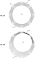
- each conductive pad in the ring was connected to a capacitance sensor (e.g., MPR121, Freescale Semiconductor, Inc.), providing a set of capacitance measurements over the surface of the ring.
- a capacitance sensor e.g., MPR121, Freescale Semiconductor, Inc.
- the positional offsets may be provided in multiple dimensions, such as two dimensions or three dimensions.
- the sampling frequency of the detection of capacitance values may be selected to be sufficiently high in order to detect patient motion in real-time or near-real-time (e.g. intrafractional motion). It will be understood that a minimum sampling frequency may depend on a wide range of factors, including, but not limited to, the type of medical procedure, patient-specific aspects of the medical procedure (e.g. the size and geometry of a tumor), and the nature (e.g. amplitude and frequency range) of motion associated with a given patient. In some example embodiments, the sampling frequency of a given electrode may be selected to be greater than 10 Hz, greater than 100 Hz, greater that 1kHz, greater than 10 kHz, or greater than 100kHz.
- calibration data is employed when processing the measured capacitance values to infer the spatial offset(s).
- the relationship between positional offset of the patient and capacitive measurements may be determined through an empirical calibration routine. For example, with the body region of the patient provided in a stationary configuration, the practitioner may apply known offsets to the capacitive position sensing device, for example, via manually or automated means. Such an embodiment avoids shifting the patient, and spatial offsets are equivalent to motion of the patient but opposite in direction. Alternatively, the body region may be translated by known amounts relative to the capacitive position sensing device.
- This calibration data set may be stored in several forms, for example, as a discrete data set that can be interpolated during subsequent processing, or parameterized, for example through curve fitting.
- This calibration procedure may be made practical and convenient for the clinical application. If the array is shifted by automated means, e.g., by actuators, this calibration may be performed in a time efficient manner. In addition, the calibration routine may be performed well in advance of the procedure and stored for later use, or performed in situ immediately prior to the procedure. Furthermore, an advantage of this empirical calibration approach is that it may be established on a per patient basis, such that the calibration data set is a per-patient calibration data set. Accordingly, if inter-patient variations exist with regard to the relationship between capacitance and positional offset, this may be accounted for during the calibration procedure.
- Additional optional design variations include the inclusion of electrical shielding and/or field focusing features.
- shielding may be provided between pads or the entire array may be shielded.
- FIGS. 8A-D show possible cross-sections of the device, where FIG. 8A shows an example embodiment in which capacitive sensing electrode 110 is provided on the back of dielectric support 120.
- FIG. 8B shows an alternative example embodiment in which an electromagnetic shielding layer 180 is included on the top surface of the dielectric support 120, as it may be advantageous in some applications to add an electromagnetic shielding layer to minimize the effects of stray electromagnetic fields in the vicinity of the device.
- a field-defining layer 190 as shown in FIG. 8C , in order to focus electric fields produced by charge on the capacitive pads to the inner region of the capacitive array. For example, an electric potential equal or close to that of the capacitive pads may be applied to the field-defining layer.
- the device may also be constructed to include both the electromagnetic shielding layer 180 and the field-defining layer 190.
- the layers of the device may be constructed of rigid or flexible materials, depending on the application.
- the electrodes and dielectric backing may be provided as a flexible substrate, such as a flex circuit.
- the dielectric support 120, electrodes 110, and electromagnetic shielding layer 180 and field-defining layer 190 should introduce minimal attenuation of the radiation beam, such that a sufficient flux and/or intensity of the beam is delivered to the body region.
- the example system includes a capacitance position sensing device 100, placed in close proximity to the body region of the patient for monitoring the positional offset thereof (in the illustrated example, the body region is the head).
- Capacitive position sensing device 100 which includes an array of capacitive sending electrodes as described above, is interfaced with capacitance detector 310, such that each electrode is separately addressable.
- the capacitance detector 310 is configured to detect the capacitance between each electrode of the array of electrodes of the capacitive positioning sensing device 100 and the body 150.
- Capacitance detector 310 may employ any suitable method of capacitance detection, including, but not limited to, any of the method described above.
- the capacitance detector 310 may provide a reference or ground connection (e.g. electrode) 312 that is brought into in electrical communication with the patient's body 150, directly or indirectly. Although, in some implementations, the patient's body may be grounded, it will be understood that grounding may not be required in order to measure capacitance.
- Capacitance detector 310 is interfaced with control and processing hardware 200, which is receives sets of capacitance values from capacitance detector 310, and optionally controls capacitance detector such that set of capacitance values are measured at prescribed time intervals.
- control and processing hardware 200 may include a processor 210, a memory 220, a system bus 205, one or more input/output devices 230, and a plurality of optional additional devices such as communications interface 260, display 240, external storage 250, and data acquisition interface 270.
- the present example methods of performing capacitive position sensing can be implemented via processor 210 and/or memory 220.
- the positional offset is calculated by control and processing hardware 200, via executable instructions represented as capacitance position processing module 290.
- the control and processing hardware 200 may include and execute instructions for planning and navigation of a medical or surgical procedure, as shown by planning and navigation module 280.
- control and processing hardware 200 may be interfaced with a medical device, such as therapeutic or surgical device 350, for providing control signals thereto.
- control and processing hardware 200 is programmed with a pre-selected offset threshold, such that when the positional offset exceeds the offset threshold, a control signal is provided to the therapeutic or surgical device 350 to interrupt its operation (e.g. turning off a radiation beam, or interrupting beam delivery via an interlock).
- a pre-selected offset threshold such that when the positional offset exceeds the offset threshold, a control signal is provided to the therapeutic or surgical device 350 to interrupt its operation (e.g. turning off a radiation beam, or interrupting beam delivery via an interlock).
- two or more thresholds may be provided, where each threshold corresponds to a different spatial direction or dimension.
- the positional offsets are provided to the therapeutic or surgical device 350 such that the therapeutic or surgical device can compensate for changes in the position of the body region.
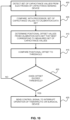
- FIG. 10 provides a flow chart illustrating an example method of controlling the operation of a therapeutic or surgical device in response to a positional offset detected with a capacitive position sensing device, where the operation of the device is interrupted when the measured offset exceeds a pre-selected threshold.
- a set of capacitance values are detected from the electrodes of the capacitance sensing device. These capacitance values processed and compared, in step 405, to a calibration data set.
- Positional offset values are then obtained, in step 410, from the calibration data set, where the positional offset values best correspond to the measured set of capacitance values.
- the positional offset values are then compared to a threshold in step 415, and if the positional offset values offset exceed the threshold (see step 420), then a control signal is sent to interrupt operation of a therapeutic or surgical device, as in step 425.
- control and processing hardware 200 provide feedback to an operator, surgeon, technician, or other user, such that the user can intervene and control the operation of the therapeutic or surgical device based on the detected positional offset.
- the control and processing hardware 200 is programmed with a pre-selected offset threshold, such that when the positional offset exceeds the offset threshold, an alert is communicated (e.g. via an audible alarm and/or visual indication on a display device).
- the detected positional offsets may be communicated to the user (e.g. via information displayed on a user interface), such that the therapeutic or surgical device, or a planning or navigation system associated with the device, can be reconfigured to compensate for changes in the position of the body region.
- the functionalities described herein can be partially implemented via hardware logic in processor 210 and partially using the instructions stored in memory 220. Some embodiments may be implemented using processor 210 without additional instructions stored in memory 220. Some embodiments are implemented using the instructions stored in memory 220 for execution by one or microprocessors. Thus, the disclosure is not limited to a specific configuration of hardware and/or software.
- control and processing hardware 200 may be provided as an external component that is interfaced to a processing device.
- capacitance detector 310 may be included as a component of control and processing hardware 200 (as shown within the dashed line), or may be provided as one or more external devices.
- At least some aspects disclosed herein can be embodied, at least in part, in software. That is, the techniques may be carried out in a computer system or other data processing system in response to its processor, such as a microprocessor, executing sequences of instructions contained in a memory, such as ROM, volatile RAM, non-volatile memory, cache or a remote storage device.
- processor such as a microprocessor
- a memory such as ROM, volatile RAM, non-volatile memory, cache or a remote storage device.
- a computer readable storage medium can be used to store software and data which when executed by a data processing system causes the system to perform various methods.
- the executable software and data may be stored in various places including for example ROM, volatile RAM, nonvolatile memory and/or cache. Portions of this software and/or data may be stored in any one of these storage devices.
- the phrases “computer readable material” and “computer readable storage medium” refers to all computer-readable media, except for a transitory propagating signal per se.
- the device could be used in any application where a rapid (e.g. real-time or near real-time), non-contact, non-invasive readout of position of the head (e.g. cranium) or other body region (i.e. portion of the human anatomy; body part) is needed.
- a rapid e.g. real-time or near real-time
- non-contact, non-invasive readout of position of the head e.g. cranium
- other body region i.e. portion of the human anatomy; body part
- the capacitive position sensing device may be made from materials that permit the passage of the beam with suitable transparency (e.g. greater than 80%, greater than 90%, greater than 95%, greater than 99%, or greater than 99.5% flux and/or intensity).
- the electrodes can be formed from a thin metallic layer, such as a thin layer of conductive paint or a thin metallic layer deposited on a substrate such as aluminized Mylar ® or Kapton ® .
- the electrodes may be formed from a material having a conductive exceeding 32 ohms for a 10 mm x 10 mm section.
- the electrodes may be connected via a conductor to capacitance detector (e.g. a circuit which measures capacitance).
- This conductor may be comprised of a shielded cable or shielded trace (e.g. formed from a thin metal layer or conductive paint), but it must not significantly attenuate the radiation therapy beam.
- adjacent capacitive pads in the array may be separated by dielectric (as in the present embodiment) or alternatively by additional conductive elements at a different potential from the capacitive pads, for example, at 0V (such as in the "parallel fingers" configuration). If the additional conductive elements are provided at a similar potential as the capacitive sensing electrodes, the electric field may be confined by the presence of the additional conductive elements.
- the capacitive positioning sensing device may include an aperture that permits the delivery of the beam to the body region.
- Example applications of the embodiments disclosed above include stereotactic radiosurgery and radiotherapy (e.g. cranial surgery). It is to be understood, however, that the radiosurgical and radiotherapeutic applications are merely provided as example applications, and that the systems and methods described herein can be applied to many other applications, such as, but not limited to, navigated surgical procedures, robotic surgery and imaging procedures.
- the methods provided herein may additionally or alternatively be employed to preoperatively screen patients for surgical interventions in order to determine whether or not a given patient is likely to be capable of maintaining a positional range during a time duration associated with a medical procedure.
- Example applications of the embodiments disclosed above include stereotactic radiosurgery and radiotherapy. Such applications may involving the following constraints: absence of highly-attenuating materials in the paths of the incoming radiation beams, which would perturb the treatment delivery; capacity to read-out the position of the patient at high temporal frequency (e.g., many times per second); measurement of patient position in two or three dimensions; the ability to monitor the position of the cranium as a whole, rather than, e.g., just the skin; and absence of unwanted ionizing radiation (e.g., unlike imaging using x-rays).
- the embodiments disclosed herein may be adapted to meet these requirements.
- the device could introduce the options of i) eliminating the invasive head-ring, replacing with the head-ring with mask immobilization combined with real-time monitoring, or ii) monitoring of the cranium for existing treatments that employ rigid mask immobilization.
- the device does not introduce significantly attenuating materials around the patient, meaning that the delivery of radiation is not perturbed. This would not be the case for other detection systems, e.g., pressure sensors or ultrasonic transducers.
- a mask, or other restraining or immobilization device having a dielectric structure may be placed between the body region and the capacitive position sensing device.
- the phrase "mask”, as used herein, refers to a restraining or immobilization structure that is placed adjacent to the region of the body.
- the mask 500 may be a thermoplastic mask configured to restrain the head of the patient during a medical procedure, as illustrated in FIG. 11 .
- the capacitance position sensing device will not track the mask position (which is not of interest and may be a poor surrogate for patient position due to the motion of the patient relative to the mask), and instead tracks the position of the patient within the mask.
- a mask may be employed to define the reference position, such that the positional offsets are measured relative to the mask, thereby tracking patient motion relative to the mask.
- the mask may be employed during calibration measurements, or included in calibration simulations, in order to account for the presence and effect of the dielectric on the measured capacitance values.
- the mask may define the dielectric substrate of the capacitance position sensing device, or at least a portion thereof, such that the electrodes are provided on or within the mask.
- the electrodes may be embedded within the mask or provided on the inner or outer surface of the mask.
- the electrodes may be formed on, or attached to, the outer surface of the mask, optionally via an additional supporting dielectric structure that contacts the mask.
- FIG. 12 An example of the latter is shown in FIG. 12 , where one or more flexible dielectric structures 510, 520 (e.g. tape) is employed to attach (mechanically couple) the capacitive sensing electrodes 530 directly to, or immediately proximal to, the surface of the mask 500.
- the use of such flexible structures e.g. tape or flexible bands
- the flexible bands could be adhesive, or individually adjustable in order to conform to various mask shapes.
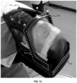
- FIG. 13 some existing patient positioning systems involve additional structural support surrounding the thermoplastic mask.
- the device shown in FIG. 13 employs a frameless support structure 600 made of low-density carbon fibre (a "frameless array").
- Reflective fiducial markers 610 spheres on anterior surface in image
- these fiducials do not track the position of the cranium itself.
- the capacitive position sensor device may be employed to detect changes in angular orientation in addition to, or in alternative to, the position sensing embodiments described above.
- the calibration data set described above may be configured to include angular-dependent calibration data in addition to, on instead of, the positional data.
- both the positional and angular offset may be monitored, thereby providing for the monitoring of six degrees of freedom in selected embodiments.
- Such embodiments may be useful to correct for misalignments in systems that are equipped with robotic compensation that can remove x, y, z as well as roll, pitch and yaw errors. Similar to the idea of shifting the array by known amounts and reading out capacitance values, the array could be rotated about the three axes by known amounts. It is noted that in some embodiments, the angular offset detection may be performed over a subset of the three angular axes. Alternatively, in some cases, small angular perturbation may be approximated by positional offsets. For example, the pitch motion is the most common in cranial patients (i.e. nodding) but the centre of rotation is quite inferior, so this translates into displacement in both the anterioposterior and superioinferior axes.
- the example capacitive position sensing device shown in FIG. 1A consisting of a very low density ring with an array of conductive pads on the cylindrical inner surface, was fabricated as a prototype.
- the materials were selected to be minimally attenuating to MV therapeutic x-ray beams.
- the dielectric support ring 120 was formed from 10% fill polylactic acid (PLA) produced by a 3D printer, however other materials would be possible in a commercial version, e.g., carbon fibre laminating a foam or hollow core.
- the conductive pads (shown black in the diagram) were formed from a very thin layer of a conductive paint (Bare Conductive, UK).
- the patient anatomy e.g., head or other anatomy
- other non-ring geometries are possible, and the device could be made to adapt readily into existing mask immobilization systems commonly used in RT or SRS.
- a computer was programmed to reads out the signals from all conductive pads (up to 12 at a time in the present example case), and calculate position of the anatomy inside the ring. The position was shown graphically on a display device.
Landscapes
- Health & Medical Sciences (AREA)
- Life Sciences & Earth Sciences (AREA)
- Engineering & Computer Science (AREA)
- Biomedical Technology (AREA)
- Surgery (AREA)
- Public Health (AREA)
- Animal Behavior & Ethology (AREA)
- Veterinary Medicine (AREA)
- General Health & Medical Sciences (AREA)
- Nuclear Medicine, Radiotherapy & Molecular Imaging (AREA)
- Pathology (AREA)
- Physics & Mathematics (AREA)
- Molecular Biology (AREA)
- Medical Informatics (AREA)
- Heart & Thoracic Surgery (AREA)
- Radiology & Medical Imaging (AREA)
- Biophysics (AREA)
- Remote Sensing (AREA)
- Oral & Maxillofacial Surgery (AREA)
- Neurosurgery (AREA)
- Physiology (AREA)
- Electromagnetism (AREA)
- Environmental & Geological Engineering (AREA)
- Geology (AREA)
- General Life Sciences & Earth Sciences (AREA)
- General Physics & Mathematics (AREA)
- Geophysics (AREA)
- Dentistry (AREA)
- Robotics (AREA)
- Radiation-Therapy Devices (AREA)
- Surgical Instruments (AREA)
- Measurement Of Length, Angles, Or The Like Using Electric Or Magnetic Means (AREA)
Claims (13)
- System zum Durchführen einer kapazitiven Überwachung der Position eines Körperbereichs während eines medizinischen Eingriffs, bei dem eine therapeutische oder chirurgische Vorrichtung (350) zum Einsatz kommt, wobei das System umfasst:eine Vorrichtung (100) zum kapazitiven Positionserfassen, umfassend:einen dielektrischen Träger (120); undeine Anordnung von Elektroden (110), die auf dem dielektrischen Träger vorgesehen oder in diesen eingebettet ist;wobei die Anordnung von Elektroden (110) zum kapazitiven Erfassen innerhalb eines Erfassungsbereichs (140) eingerichtet ist, wobei der Erfassungsbereich (140) zum Positionieren wenigstens eines Teils des Körperbereichs darin geeignet ist, so dass der Körperbereich in einer Referenzposition innerhalb des Erfassungsbereichs positionierbar ist, ohne die Anordnung von Elektroden zu berühren;Steuer- und Verarbeitungshardware (200), die mit der Vorrichtung (100) zum kapazitiven Positionserfassen wirkgekoppelt ist, wobei die Steuer- und Verarbeitungshardware (200) mit der therapeutischen oder chirurgischen Vorrichtung (350) zum Senden eines Steuersignals an diese verbindbar ist, und wobei die Steuer- und Verarbeitungshardware (200) eingerichtet ist, um Vorgänge durchzuführen, umfassend:Erfassen einer Kapazität zwischen jeder der Elektroden (110) und dem Körperbereich, wodurch ein Satz von gemessenen Kapazitätswerten erhalten wird;Verarbeiten des Satzes von gemessenen Kapazitätswerten, um einen Versatz des Körperbereichs relativ zu der Referenzposition zu bestimmen; undwenigstens eines von Folgendem:
Bereitstellen des Steuersignals an die therapeutische oder chirurgische Vorrichtung (350) basierend auf dem Versatz; und Bereitstellen eines Alarms, um den medizinischen Eingriff zu unterbrechen, wenn der Versatz einen Schwellenwert überschreitet;wobei die Anordnung von Elektroden (110) in einer dreidimensionalen Konfiguration eingerichtet ist,wobei der Versatz wenigstens einen von einem Positionsversatz und einem Winkelversatz umfasst,wobei die Steuer- und Verarbeitungshardware (200) betreibbar ist, um wenigstens einen von dem Positionsversatz und dem Winkelversatz des Körperbereichs in zwei oder drei Dimensionen zu bestimmen,wobei das System eingerichtet ist, um den Satz von gemessenen Kapazitätswerten zu verarbeiten, um den Winkelversatz des Körperbereichs um eine oder mehrere Achsen relativ zu der Referenzposition zu bestimmen, undwobei das Verarbeiten des Satzes von gemessenen Kapazitätswerten das Erhalten von Kalibrierungsdaten für jede Elektrode (110) der Anordnung von Elektroden (110) umfasst, wobei die Kalibrierungsdaten für jede Elektrode (110) eine Beziehung zwischen Kapazität und Positionsversatz herstellen. - System nach Anspruch 1, wobei der Versatz einen Positionsversatz umfasst und das Verarbeiten des Satzes von gemessenen Kapazitätswerten umfasst:Erhalten von Kalibrierungsdaten für jede Elektrode (110) der Anordnung von Elektroden (110), wobei die Kalibrierungsdaten für jede Elektrode (110) eine Beziehung zwischen Kapazität und Positionsversatz herstellen;Verarbeiten des Satzes von gemessenen Kapazitätswerten und der Kalibrierungsdaten, um Positionsversätze zu bestimmen, die zu einem Satz von Kalibrierungskapazitätswerten für die Anordnung von Elektroden (110) führen, die am besten zu dem Satz von gemessenen Kapazitätswerten passen.
- System nach einem der Ansprüche 1 bis 2, wobei der Versatz einen Positionsversatz umfasst und das System eingerichtet ist, um den Positionsversatz an die therapeutische oder chirurgische Vorrichtung (350) bereitzustellen, so dass die therapeutische oder chirurgische Vorrichtung (350) Änderungen der Position des Körperbereichs kompensieren kann.
- System nach Anspruch 1, wobei der Versatz einen Positionsversatz umfasst und das System eingerichtet ist, um eine Position und/oder Ausrichtung der therapeutischen oder chirurgischen Vorrichtung (350) zu steuern, um Änderungen der Position des Körperbereichs zu kompensieren.
- System nach einem der Ansprüche 1 bis 4, wobei die Steuer- und Verarbeitungshardware (200) mit einem zuvor ausgewählten Versatzschwellenwert programmiert ist, so dass, wenn der Positionsversatz den Versatzschwellenwert überschreitet, ein Steuersignal an die therapeutische oder chirurgische Vorrichtung (350) bereitgestellt wird, um einen Betrieb der therapeutischen oder chirurgischen Vorrichtung (350) zu unterbrechen.
- System nach einem der Ansprüche 1 bis 5, wobei die Elektroden (110) der Anordnung von Elektroden (110) in einer kugelförmigen Konfiguration angeordnet sind.
- System nach einem der Ansprüche 1 bis 5, wobei die Anordnung von Elektroden (110) eine erste zylindrische Anordnung (121) und wenigstens eine zusätzliche zylindrische Anordnung (122) umfasst, wobei eine erste Achse, die der ersten zylindrischen Anordnung (121) zugeordnet ist, und eine zusätzliche Achse, die jeder zusätzlichen zylindrischen Anordnung (122) zugeordnet ist, in unterschiedliche Richtungen ausgerichtet sind.
- System nach einem der Ansprüche 1 bis 7, wobei die therapeutische oder chirurgische Vorrichtung (350) betreibbar ist, um einen Energiestrahl abzugeben, der aus der Gruppe ausgewählt ist bestehend aus Photonenenergiestrahlen, Teilchenstrahlen und hochintensivem fokussiertem Ultraschall.
- System nach Anspruch 8, wobei wenigstens ein Teil der Vorrichtung (100) zum kapazitiven Positionserfassen aus einem Material gebildet ist, das eine Dicke und Zusammensetzung aufweist, die zum Übertragen wenigstens eines Teils des Energiestrahls geeignet ist, wobei der Teil der Vorrichtung zum kapazitiven Positionserfassen vorzugsweise Elektroden umfasst, die aus einem dünnen Film gebildet sind, der zum Übertragen von wenigstens 95 Prozent des Energiestrahls geeignet ist.
- System nach einem der Ansprüche 1 bis 5, wobei die Referenzposition wenigstens teilweise durch eine Maske (500) definiert ist, die eingerichtet ist, um benachbart zu dem Körperbereich platziert zu sein, und wobei die Maske (500) aus einem dielektrischen Material gebildet ist, so dass wenigstens einige der Elektroden (110) derart angeordnet sind, dass die entsprechenden Kapazitätswerte durch die Maske (500) gemessen werden, wobei vorzugsweise eine oder beide der Maske (500) und einer Tragstruktur, die dieser zugeordnet ist, wenigstens einen Teil der Vorrichtung (100) zum kapazitiven Positionserfassen bilden, so dass die Maske (500) und/oder die Tragstruktur die Anordnung von Elektroden (110) umfasst, und wobei wenigstens eine dielektrische Schicht zwischen jeder Elektrode und dem Körperbereich vorhanden ist.
- System nach einem der Ansprüche 1 bis 10, wobei das System verbunden ist, um die therapeutische oder chirurgische Vorrichtung (350) basierend auf sowohl dem Positionsversatz als auch dem Winkelversatz zu steuern.
- System nach Anspruch 1, wobei der Versatz einen Winkelversatz umfasst.
- System nach einem der Ansprüche 1 bis 12, wobei das Verarbeiten des Satzes von gemessenen Kapazitätswerten umfasst:Verarbeiten des Satzes von gemessenen Kapazitätswerten und der Kalibrierungsdaten, um Positionsversätze zu bestimmen, die zu einem Satz von Kalibrierungskapazitätswerten für die Anordnung von Elektroden (110) führen, der am besten zu dem Satz von gemessenen Kapazitätswerten passt,wobei sich die Kalibrierungsdaten vorzugsweise auf Kalibrierungsmessungen des Körperbereichs beziehen, die an mehreren bekannten Positionen relativ zu der Referenzposition erhalten wurden, oder wobei die Kalibrierungsdaten aus mehreren Finite-Elemente-Simulationen erhalten werden, wobei jede Finite-Elemente-Simulation einen Satz von Kapazitätswerten umfasst, die bei einem eindeutigen räumlichen Versatz berechnet wurden.
Applications Claiming Priority (2)
| Application Number | Priority Date | Filing Date | Title |
|---|---|---|---|
| US201562242808P | 2015-10-16 | 2015-10-16 | |
| PCT/CA2016/051192 WO2017063084A1 (en) | 2015-10-16 | 2016-10-13 | Systems and methods for monitoring patient motion via capacitive position sensing |
Publications (3)
| Publication Number | Publication Date |
|---|---|
| EP3361978A1 EP3361978A1 (de) | 2018-08-22 |
| EP3361978A4 EP3361978A4 (de) | 2019-05-29 |
| EP3361978B1 true EP3361978B1 (de) | 2025-07-02 |
Family
ID=58516937
Family Applications (1)
| Application Number | Title | Priority Date | Filing Date |
|---|---|---|---|
| EP16854682.8A Active EP3361978B1 (de) | 2015-10-16 | 2016-10-13 | Systeme zur überwachung der patientenbewegung über kapazitive positionserfassung |
Country Status (3)
| Country | Link |
|---|---|
| US (3) | US10857390B2 (de) |
| EP (1) | EP3361978B1 (de) |
| WO (1) | WO2017063084A1 (de) |
Families Citing this family (8)
| Publication number | Priority date | Publication date | Assignee | Title |
|---|---|---|---|---|
| WO2020082012A1 (en) | 2018-10-18 | 2020-04-23 | Zap Surgical Systems, Inc. | Positioning and motion tracking using force sensing |
| EP3897828A4 (de) * | 2018-12-21 | 2022-09-07 | Dalhousie University | Vorrichtung und verfahren zur gating-abgabe von strahlung basierend auf der kapazitiven überwachung der atmungsbewegung |
| US11504193B2 (en) | 2019-05-21 | 2022-11-22 | Verb Surgical Inc. | Proximity sensors for surgical robotic arm manipulation |
| US11278361B2 (en) | 2019-05-21 | 2022-03-22 | Verb Surgical Inc. | Sensors for touch-free control of surgical robotic systems |
| EP4072412A1 (de) * | 2019-12-10 | 2022-10-19 | Brainlab AG | Verfahren und vorrichtung zum bestimmen der verlagerung eines inneren organs |
| JP2024511277A (ja) | 2021-02-19 | 2024-03-13 | メビオン・メディカル・システムズ・インコーポレーテッド | 粒子線治療システムのためのガントリー |
| CN114305390B (zh) * | 2021-12-29 | 2023-09-05 | 北京航空航天大学 | 用于足底压力检测和滑移校准的装置及检测方法 |
| CN117243699B (zh) * | 2023-11-14 | 2024-03-15 | 杭州三坛医疗科技有限公司 | 一种移位检测方法及装置 |
Family Cites Families (37)
| Publication number | Priority date | Publication date | Assignee | Title |
|---|---|---|---|---|
| AU7986682A (en) * | 1981-02-12 | 1982-08-19 | New York University | Apparatus for stereotactic surgery |
| US5947981A (en) | 1995-01-31 | 1999-09-07 | Cosman; Eric R. | Head and neck localizer |
| US5279309A (en) * | 1991-06-13 | 1994-01-18 | International Business Machines Corporation | Signaling device and method for monitoring positions in a surgical operation |
| US5914465A (en) | 1992-06-08 | 1999-06-22 | Synaptics, Inc. | Object position detector |
| US5410297A (en) | 1993-01-11 | 1995-04-25 | R. F. Technologies, Inc. | Capacitive patient presence monitor |
| US5463388A (en) | 1993-01-29 | 1995-10-31 | At&T Ipm Corp. | Computer mouse or keyboard input device utilizing capacitive sensors |
| DE4432890B4 (de) | 1994-09-15 | 2004-02-19 | Brainlab Ag | Vorrichtung zum Erfassen der Position von Bestrahlungszielpunkten |
| DE4432891C2 (de) * | 1994-09-15 | 2003-11-06 | Brainlab Ag | Vorrichtung und Maskenteilesatz zur nicht invasiven stereotaktischen Immobilisation in reproduzierbarer Position |
| US6122541A (en) * | 1995-05-04 | 2000-09-19 | Radionics, Inc. | Head band for frameless stereotactic registration |
| US5651044A (en) * | 1995-10-02 | 1997-07-22 | General Electric Company | Capacitive proximity detector for radiation imager position control |
| US5805664A (en) * | 1995-10-02 | 1998-09-08 | General Electric Company | Imager control system with contact detector |
| US6288707B1 (en) | 1996-07-29 | 2001-09-11 | Harald Philipp | Capacitive position sensor |
| US6025782A (en) | 1996-09-04 | 2000-02-15 | Newham; Paul | Device for monitoring the presence of a person using proximity induced dielectric shift sensing |
| US6661240B1 (en) | 2000-10-04 | 2003-12-09 | General Electric Co. | Methods and systems for capacitive motion sensing and position control |
| US6768921B2 (en) | 2000-12-28 | 2004-07-27 | Z-Tech (Canada) Inc. | Electrical impedance method and apparatus for detecting and diagnosing diseases |
| FR2844349B1 (fr) * | 2002-09-06 | 2005-06-24 | Nanotec Solution | Detecteur de proximite par capteur capacitif |
| DE102004018630A1 (de) | 2004-04-16 | 2005-11-10 | Pepperl + Fuchs Gmbh | Vorrichtung, Sensoranordnung und Verfahren zur kapazitiven Positionserfassung eines Zielobjekts |
| US10195464B2 (en) * | 2004-06-24 | 2019-02-05 | Varian Medical Systems, Inc. | Systems and methods for treating a lung of a patient using guided radiation therapy or surgery |
| US8095203B2 (en) * | 2004-07-23 | 2012-01-10 | Varian Medical Systems, Inc. | Data processing for real-time tracking of a target in radiation therapy |
| US20060030182A1 (en) | 2004-07-29 | 2006-02-09 | Rf Technologies, Inc. | Patient presence monitoring system and method |
| WO2006094156A2 (en) * | 2005-03-02 | 2006-09-08 | Calypso Medical Technologies, Inc. | Systems and methods for treating a patient using guided radiation therapy or surgery |
| CN101188969B (zh) | 2005-06-07 | 2010-09-29 | 皇家飞利浦电子股份有限公司 | 患者监护系统和方法 |
| US8482530B2 (en) | 2006-11-13 | 2013-07-09 | Apple Inc. | Method of capacitively sensing finger position |
| US7623623B2 (en) * | 2007-06-29 | 2009-11-24 | Accuray Incorporated | Non-collocated imaging and treatment in image-guided radiation treatment systems |
| EP2211721B1 (de) | 2007-11-19 | 2019-07-10 | Pyronia Medical Technologies, Inc. | Patientenpositionierungssystem und entsprechende verfahren für diagnostische radiologie und radiotherapie |
| JP4793422B2 (ja) | 2008-10-10 | 2011-10-12 | ソニー株式会社 | 情報処理装置、情報処理方法、情報処理システムおよび情報処理用プログラム |
| US8330474B2 (en) | 2008-10-15 | 2012-12-11 | Synaptics Incorporated | Sensor device and method with at surface object sensing and away from surface object sensing |
| JP4816713B2 (ja) | 2008-11-25 | 2011-11-16 | ソニー株式会社 | 情報処理装置、情報処理方法および情報処理用プログラム |
| KR20110129484A (ko) | 2009-03-24 | 2011-12-01 | 가부시키가이샤후지쿠라 | 헤드레스트와 머리부 사이의 거리측정장치, 헤드레스트와 머리부 사이의 거리측정방법, 헤드레스트 위치조정장치, 및 헤드레스트 위치조정방법 |
| CN103889506B (zh) | 2011-08-16 | 2016-10-05 | 皇家飞利浦有限公司 | 一种治疗规划系统及治疗系统 |
| US9665214B2 (en) | 2012-03-29 | 2017-05-30 | Synaptics Incorporated | System and methods for determining object information using selectively floated electrodes |
| US11083401B2 (en) * | 2012-08-09 | 2021-08-10 | Northeastern University | Electric field encephalography: electric field based brain signal detection and monitoring |
| JP2015222456A (ja) | 2012-09-19 | 2015-12-10 | アルプス電気株式会社 | 静電容量式センサ |
| DE102013201830A1 (de) * | 2013-02-05 | 2014-08-07 | Siemens Aktiengesellschaft | Medizinische Bildgebungsvorrichtung mit einer Bewegungserfassungseinheit sowie ein Verfahren zu einer Erfassung einer Patientenbewegung |
| US20160054853A1 (en) | 2013-05-07 | 2016-02-25 | Yingzhe Hu | System and method for 3d position and gesture sensing of human hand |
| EP3010408B1 (de) | 2013-06-21 | 2022-08-10 | Northeastern University | Sensorsystem und verfahren zur messung der elektrischen aktivität des gehirns einschliesslich elektroenzephalografie |
| JP2017090942A (ja) | 2014-03-19 | 2017-05-25 | アルプス電気株式会社 | 入力装置 |
-
2016
- 2016-10-13 US US15/767,325 patent/US10857390B2/en active Active
- 2016-10-13 EP EP16854682.8A patent/EP3361978B1/de active Active
- 2016-10-13 WO PCT/CA2016/051192 patent/WO2017063084A1/en not_active Ceased
-
2020
- 2020-11-06 US US17/092,129 patent/US11612763B2/en active Active
-
2023
- 2023-02-15 US US18/110,304 patent/US11911632B2/en active Active
Also Published As
| Publication number | Publication date |
|---|---|
| EP3361978A4 (de) | 2019-05-29 |
| US11911632B2 (en) | 2024-02-27 |
| US20180296857A1 (en) | 2018-10-18 |
| US20230226376A1 (en) | 2023-07-20 |
| WO2017063084A1 (en) | 2017-04-20 |
| US11612763B2 (en) | 2023-03-28 |
| EP3361978A1 (de) | 2018-08-22 |
| US20210077829A1 (en) | 2021-03-18 |
| US10857390B2 (en) | 2020-12-08 |
Similar Documents
| Publication | Publication Date | Title |
|---|---|---|
| US11911632B2 (en) | Systems and methods for monitoring patient motion via capacitive position sensing | |
| Rowshanfarzad et al. | Isocenter verification for linac‐based stereotactic radiation therapy: review of principles and techniques | |
| JP5264075B2 (ja) | 生体内マーカを使ったターゲットの位置特定 | |
| EP3238651B1 (de) | Echtzeitfusion von anatomischen ultraschallinformationen und strahlenabgabeinformationen für die strahlentherapie | |
| Chen et al. | A review of image-guided radiotherapy | |
| EP2086639B1 (de) | On-line verifikationsystem für imrt | |
| CN114845767A (zh) | 用于管理由交变场感应的温度的方法、系统和装置 | |
| EP2821100B1 (de) | Behandlungsplanungsvorrichtung, behandlungsplanungsverfahren und programm dafür | |
| Pantelis et al. | On the total system error of a robotic radiosurgery system: phantom measurements, clinical evaluation and long-term analysis | |
| Ricotti et al. | Long-time clinical experience in patient setup for several particle therapy clinical indications: management of patient positioning and evaluation of setup reproducibility and stability | |
| Khaledi et al. | Historical progress of stereotactic radiation surgery | |
| US20140213904A1 (en) | Intra-fraction motion management system | |
| Županič et al. | Optimization and numerical modeling in irreversible electroporation treatment planning | |
| KR102896238B1 (ko) | 생체 임피던스 측정 및 전기 자극을 위한 장치 및 방법 | |
| US20200330797A1 (en) | Real time and non-invasive in vivo dosimetry and tissue monitoring using electrical impedance tomography for radiation therapy | |
| TW202042864A (zh) | 放射治療系統、控制醫療儀器的控制方法及控制裝置 | |
| Kim et al. | In-house developed surface-guided repositioning and monitoring system to complement in-room patient positioning system for spine radiosurgery | |
| Radzi et al. | Experiencing In-vivo dosimetry verification in Malaysia: A patient-specific EPID-based approach | |
| Kumar et al. | Simultaneous measurement of in vivo and transit Mid-Plane doses with ionization chambers in gynecological malignancy patients undergoing Three-Dimensional conformal radiotherapy | |
| Kairn | Intensity-modulated radiotherapy and volumetric-modulated arc therapy | |
| Taneja et al. | Patient Specific Quality Assurance | |
| Liu | Patient-specific planning target volume margins for liver stereotactic robotic radiosurgery | |
| Weidlich et al. | Clinical commissioning of Laitinen Stereoadapter for fractionated stereotactic radiotherapy | |
| TW202537655A (zh) | 選擇用於遞送交變電場之換能器的尺寸 | |
| Al-Mohammed et al. | Patient-specific quality assurance for the treatment of intensity modality radiation therapy of nasopharyngeal carcinoma |
Legal Events
| Date | Code | Title | Description |
|---|---|---|---|
| STAA | Information on the status of an ep patent application or granted ep patent |
Free format text: STATUS: THE INTERNATIONAL PUBLICATION HAS BEEN MADE |
|
| PUAI | Public reference made under article 153(3) epc to a published international application that has entered the european phase |
Free format text: ORIGINAL CODE: 0009012 |
|
| STAA | Information on the status of an ep patent application or granted ep patent |
Free format text: STATUS: REQUEST FOR EXAMINATION WAS MADE |
|
| 17P | Request for examination filed |
Effective date: 20180412 |
|
| AK | Designated contracting states |
Kind code of ref document: A1 Designated state(s): AL AT BE BG CH CY CZ DE DK EE ES FI FR GB GR HR HU IE IS IT LI LT LU LV MC MK MT NL NO PL PT RO RS SE SI SK SM TR |
|
| AX | Request for extension of the european patent |
Extension state: BA ME |
|
| DAV | Request for validation of the european patent (deleted) | ||
| DAX | Request for extension of the european patent (deleted) | ||
| A4 | Supplementary search report drawn up and despatched |
Effective date: 20190502 |
|
| RIC1 | Information provided on ipc code assigned before grant |
Ipc: A61B 90/14 20160101ALI20190425BHEP Ipc: A61B 5/05 20060101ALI20190425BHEP Ipc: A61B 34/30 20160101ALI20190425BHEP Ipc: G01V 3/08 20060101ALI20190425BHEP Ipc: A61B 5/11 20060101ALI20190425BHEP Ipc: A61B 34/20 20160101AFI20190425BHEP |
|
| STAA | Information on the status of an ep patent application or granted ep patent |
Free format text: STATUS: EXAMINATION IS IN PROGRESS |
|
| 17Q | First examination report despatched |
Effective date: 20211223 |
|
| GRAP | Despatch of communication of intention to grant a patent |
Free format text: ORIGINAL CODE: EPIDOSNIGR1 |
|
| STAA | Information on the status of an ep patent application or granted ep patent |
Free format text: STATUS: GRANT OF PATENT IS INTENDED |
|
| INTG | Intention to grant announced |
Effective date: 20250313 |
|
| GRAS | Grant fee paid |
Free format text: ORIGINAL CODE: EPIDOSNIGR3 |
|
| GRAA | (expected) grant |
Free format text: ORIGINAL CODE: 0009210 |
|
| STAA | Information on the status of an ep patent application or granted ep patent |
Free format text: STATUS: THE PATENT HAS BEEN GRANTED |
|
| AK | Designated contracting states |
Kind code of ref document: B1 Designated state(s): AL AT BE BG CH CY CZ DE DK EE ES FI FR GB GR HR HU IE IS IT LI LT LU LV MC MK MT NL NO PL PT RO RS SE SI SK SM TR |
|
| P01 | Opt-out of the competence of the unified patent court (upc) registered |
Free format text: CASE NUMBER: APP_24784/2025 Effective date: 20250523 |
|
| REG | Reference to a national code |
Ref country code: GB Ref legal event code: FG4D |
|
| REG | Reference to a national code |
Ref country code: CH Ref legal event code: EP |
|
| REG | Reference to a national code |
Ref country code: DE Ref legal event code: R096 Ref document number: 602016092786 Country of ref document: DE |
|
| REG | Reference to a national code |
Ref country code: IE Ref legal event code: FG4D |
|
| REG | Reference to a national code |
Ref country code: NL Ref legal event code: MP Effective date: 20250702 |
|
| PG25 | Lapsed in a contracting state [announced via postgrant information from national office to epo] |
Ref country code: PT Free format text: LAPSE BECAUSE OF FAILURE TO SUBMIT A TRANSLATION OF THE DESCRIPTION OR TO PAY THE FEE WITHIN THE PRESCRIBED TIME-LIMIT Effective date: 20251103 |
|
| PG25 | Lapsed in a contracting state [announced via postgrant information from national office to epo] |
Ref country code: NL Free format text: LAPSE BECAUSE OF FAILURE TO SUBMIT A TRANSLATION OF THE DESCRIPTION OR TO PAY THE FEE WITHIN THE PRESCRIBED TIME-LIMIT Effective date: 20250702 |
|
| REG | Reference to a national code |
Ref country code: AT Ref legal event code: MK05 Ref document number: 1808370 Country of ref document: AT Kind code of ref document: T Effective date: 20250702 |
|
| PG25 | Lapsed in a contracting state [announced via postgrant information from national office to epo] |
Ref country code: IS Free format text: LAPSE BECAUSE OF FAILURE TO SUBMIT A TRANSLATION OF THE DESCRIPTION OR TO PAY THE FEE WITHIN THE PRESCRIBED TIME-LIMIT Effective date: 20251102 |
|
| PGFP | Annual fee paid to national office [announced via postgrant information from national office to epo] |
Ref country code: DE Payment date: 20251029 Year of fee payment: 10 |
|
| PGFP | Annual fee paid to national office [announced via postgrant information from national office to epo] |
Ref country code: GB Payment date: 20251024 Year of fee payment: 10 |
|
| PG25 | Lapsed in a contracting state [announced via postgrant information from national office to epo] |
Ref country code: NO Free format text: LAPSE BECAUSE OF FAILURE TO SUBMIT A TRANSLATION OF THE DESCRIPTION OR TO PAY THE FEE WITHIN THE PRESCRIBED TIME-LIMIT Effective date: 20251002 |
|
| REG | Reference to a national code |
Ref country code: LT Ref legal event code: MG9D |
|
| PG25 | Lapsed in a contracting state [announced via postgrant information from national office to epo] |
Ref country code: AT Free format text: LAPSE BECAUSE OF FAILURE TO SUBMIT A TRANSLATION OF THE DESCRIPTION OR TO PAY THE FEE WITHIN THE PRESCRIBED TIME-LIMIT Effective date: 20250702 |
|
| PG25 | Lapsed in a contracting state [announced via postgrant information from national office to epo] |
Ref country code: FI Free format text: LAPSE BECAUSE OF FAILURE TO SUBMIT A TRANSLATION OF THE DESCRIPTION OR TO PAY THE FEE WITHIN THE PRESCRIBED TIME-LIMIT Effective date: 20250702 |
|
| PG25 | Lapsed in a contracting state [announced via postgrant information from national office to epo] |
Ref country code: HR Free format text: LAPSE BECAUSE OF FAILURE TO SUBMIT A TRANSLATION OF THE DESCRIPTION OR TO PAY THE FEE WITHIN THE PRESCRIBED TIME-LIMIT Effective date: 20250702 |
|
| PGFP | Annual fee paid to national office [announced via postgrant information from national office to epo] |
Ref country code: FR Payment date: 20251027 Year of fee payment: 10 |
|
| PG25 | Lapsed in a contracting state [announced via postgrant information from national office to epo] |
Ref country code: GR Free format text: LAPSE BECAUSE OF FAILURE TO SUBMIT A TRANSLATION OF THE DESCRIPTION OR TO PAY THE FEE WITHIN THE PRESCRIBED TIME-LIMIT Effective date: 20251003 |
|
| PG25 | Lapsed in a contracting state [announced via postgrant information from national office to epo] |
Ref country code: SE Free format text: LAPSE BECAUSE OF FAILURE TO SUBMIT A TRANSLATION OF THE DESCRIPTION OR TO PAY THE FEE WITHIN THE PRESCRIBED TIME-LIMIT Effective date: 20250702 Ref country code: CZ Free format text: LAPSE BECAUSE OF FAILURE TO SUBMIT A TRANSLATION OF THE DESCRIPTION OR TO PAY THE FEE WITHIN THE PRESCRIBED TIME-LIMIT Effective date: 20250702 |
|
| PG25 | Lapsed in a contracting state [announced via postgrant information from national office to epo] |
Ref country code: LV Free format text: LAPSE BECAUSE OF FAILURE TO SUBMIT A TRANSLATION OF THE DESCRIPTION OR TO PAY THE FEE WITHIN THE PRESCRIBED TIME-LIMIT Effective date: 20250702 |
|
| PG25 | Lapsed in a contracting state [announced via postgrant information from national office to epo] |
Ref country code: PL Free format text: LAPSE BECAUSE OF FAILURE TO SUBMIT A TRANSLATION OF THE DESCRIPTION OR TO PAY THE FEE WITHIN THE PRESCRIBED TIME-LIMIT Effective date: 20250702 Ref country code: BG Free format text: LAPSE BECAUSE OF FAILURE TO SUBMIT A TRANSLATION OF THE DESCRIPTION OR TO PAY THE FEE WITHIN THE PRESCRIBED TIME-LIMIT Effective date: 20250702 |
|
| PG25 | Lapsed in a contracting state [announced via postgrant information from national office to epo] |
Ref country code: RS Free format text: LAPSE BECAUSE OF FAILURE TO SUBMIT A TRANSLATION OF THE DESCRIPTION OR TO PAY THE FEE WITHIN THE PRESCRIBED TIME-LIMIT Effective date: 20251002 |
|
| PG25 | Lapsed in a contracting state [announced via postgrant information from national office to epo] |
Ref country code: ES Free format text: LAPSE BECAUSE OF FAILURE TO SUBMIT A TRANSLATION OF THE DESCRIPTION OR TO PAY THE FEE WITHIN THE PRESCRIBED TIME-LIMIT Effective date: 20250702 |
|
| PG25 | Lapsed in a contracting state [announced via postgrant information from national office to epo] |
Ref country code: RO Free format text: LAPSE BECAUSE OF FAILURE TO SUBMIT A TRANSLATION OF THE DESCRIPTION OR TO PAY THE FEE WITHIN THE PRESCRIBED TIME-LIMIT Effective date: 20250702 |
|
| PG25 | Lapsed in a contracting state [announced via postgrant information from national office to epo] |
Ref country code: SM Free format text: LAPSE BECAUSE OF FAILURE TO SUBMIT A TRANSLATION OF THE DESCRIPTION OR TO PAY THE FEE WITHIN THE PRESCRIBED TIME-LIMIT Effective date: 20250702 |
|
| PG25 | Lapsed in a contracting state [announced via postgrant information from national office to epo] |
Ref country code: DK Free format text: LAPSE BECAUSE OF FAILURE TO SUBMIT A TRANSLATION OF THE DESCRIPTION OR TO PAY THE FEE WITHIN THE PRESCRIBED TIME-LIMIT Effective date: 20250702 |
|
| PG25 | Lapsed in a contracting state [announced via postgrant information from national office to epo] |
Ref country code: IT Free format text: LAPSE BECAUSE OF FAILURE TO SUBMIT A TRANSLATION OF THE DESCRIPTION OR TO PAY THE FEE WITHIN THE PRESCRIBED TIME-LIMIT Effective date: 20250702 |
|
| PG25 | Lapsed in a contracting state [announced via postgrant information from national office to epo] |
Ref country code: EE Free format text: LAPSE BECAUSE OF FAILURE TO SUBMIT A TRANSLATION OF THE DESCRIPTION OR TO PAY THE FEE WITHIN THE PRESCRIBED TIME-LIMIT Effective date: 20250702 Ref country code: SK Free format text: LAPSE BECAUSE OF FAILURE TO SUBMIT A TRANSLATION OF THE DESCRIPTION OR TO PAY THE FEE WITHIN THE PRESCRIBED TIME-LIMIT Effective date: 20250702 |