EP3361962B1 - Ballonnet gonflable à usage médical - Google Patents
Ballonnet gonflable à usage médical Download PDFInfo
- Publication number
- EP3361962B1 EP3361962B1 EP16806211.5A EP16806211A EP3361962B1 EP 3361962 B1 EP3361962 B1 EP 3361962B1 EP 16806211 A EP16806211 A EP 16806211A EP 3361962 B1 EP3361962 B1 EP 3361962B1
- Authority
- EP
- European Patent Office
- Prior art keywords
- balloon
- sole
- wall
- medical use
- endoscope
- Prior art date
- Legal status (The legal status is an assumption and is not a legal conclusion. Google has not performed a legal analysis and makes no representation as to the accuracy of the status listed.)
- Active
Links
Images

Classifications
-
- A—HUMAN NECESSITIES
- A61—MEDICAL OR VETERINARY SCIENCE; HYGIENE
- A61B—DIAGNOSIS; SURGERY; IDENTIFICATION
- A61B17/00—Surgical instruments, devices or methods
- A61B17/24—Surgical instruments, devices or methods for use in the oral cavity, larynx, bronchial passages or nose; Tongue scrapers
-
- A—HUMAN NECESSITIES
- A61—MEDICAL OR VETERINARY SCIENCE; HYGIENE
- A61B—DIAGNOSIS; SURGERY; IDENTIFICATION
- A61B1/00—Instruments for performing medical examinations of the interior of cavities or tubes of the body by visual or photographical inspection, e.g. endoscopes; Illuminating arrangements therefor
- A61B1/00064—Constructional details of the endoscope body
- A61B1/00071—Insertion part of the endoscope body
- A61B1/0008—Insertion part of the endoscope body characterised by distal tip features
- A61B1/00082—Balloons
-
- A—HUMAN NECESSITIES
- A61—MEDICAL OR VETERINARY SCIENCE; HYGIENE
- A61B—DIAGNOSIS; SURGERY; IDENTIFICATION
- A61B17/00—Surgical instruments, devices or methods
- A61B17/12—Surgical instruments, devices or methods for ligaturing or otherwise compressing tubular parts of the body, e.g. blood vessels or umbilical cord
- A61B17/12022—Occluding by internal devices, e.g. balloons or releasable wires
- A61B17/12099—Occluding by internal devices, e.g. balloons or releasable wires characterised by the location of the occluder
- A61B17/12104—Occluding by internal devices, e.g. balloons or releasable wires characterised by the location of the occluder in an air passage
-
- A—HUMAN NECESSITIES
- A61—MEDICAL OR VETERINARY SCIENCE; HYGIENE
- A61B—DIAGNOSIS; SURGERY; IDENTIFICATION
- A61B17/00—Surgical instruments, devices or methods
- A61B17/12—Surgical instruments, devices or methods for ligaturing or otherwise compressing tubular parts of the body, e.g. blood vessels or umbilical cord
- A61B17/12022—Occluding by internal devices, e.g. balloons or releasable wires
- A61B17/12131—Occluding by internal devices, e.g. balloons or releasable wires characterised by the type of occluding device
- A61B17/12136—Balloons
-
- A—HUMAN NECESSITIES
- A61—MEDICAL OR VETERINARY SCIENCE; HYGIENE
- A61M—DEVICES FOR INTRODUCING MEDIA INTO, OR ONTO, THE BODY; DEVICES FOR TRANSDUCING BODY MEDIA OR FOR TAKING MEDIA FROM THE BODY; DEVICES FOR PRODUCING OR ENDING SLEEP OR STUPOR
- A61M25/00—Catheters; Hollow probes
- A61M25/10—Balloon catheters
- A61M25/1018—Balloon inflating or inflation-control devices
- A61M25/10184—Means for controlling or monitoring inflation or deflation
- A61M25/10185—Valves
-
- A—HUMAN NECESSITIES
- A61—MEDICAL OR VETERINARY SCIENCE; HYGIENE
- A61B—DIAGNOSIS; SURGERY; IDENTIFICATION
- A61B17/00—Surgical instruments, devices or methods
- A61B17/00234—Surgical instruments, devices or methods for minimally invasive surgery
- A61B2017/00292—Surgical instruments, devices or methods for minimally invasive surgery mounted on or guided by flexible, e.g. catheter-like, means
- A61B2017/00296—Surgical instruments, devices or methods for minimally invasive surgery mounted on or guided by flexible, e.g. catheter-like, means mounted on an endoscope
-
- A—HUMAN NECESSITIES
- A61—MEDICAL OR VETERINARY SCIENCE; HYGIENE
- A61M—DEVICES FOR INTRODUCING MEDIA INTO, OR ONTO, THE BODY; DEVICES FOR TRANSDUCING BODY MEDIA OR FOR TAKING MEDIA FROM THE BODY; DEVICES FOR PRODUCING OR ENDING SLEEP OR STUPOR
- A61M25/00—Catheters; Hollow probes
- A61M25/10—Balloon catheters
- A61M2025/1043—Balloon catheters with special features or adapted for special applications
- A61M2025/1084—Balloon catheters with special features or adapted for special applications having features for increasing the shape stability, the reproducibility or for limiting expansion, e.g. containments, wrapped around fibres, yarns or strands
Definitions
- the present invention relates to an inflatable balloon for medical use, intended to be inserted deflated in a human or animal body cavity and then inflated inside this cavity in order to apply pressure against the walls of this cavity.
- a balloon of this type is inserted into the nasal cavity of a patient, then inflated once correctly positioned using a fluid such as air or gelled water.
- a fluid such as air or gelled water.
- a difficulty in the use of this type of balloon is the insertion and positioning of the balloon in the cavity, in particular when it is an insertion in the nasal cavity.
- Document WO 96/39218 discloses an inflatable nasal tamponade device having a flexible base which can be introduced through the nasal cavity to enter the nasopharynx.
- a first airbag is attached to the anterior part of the base and remains inside the nasal cavity
- a second airbag is attached to the posterior part of the base and enters the nasopharynx.
- These bags completely surround the base and are much larger than the corresponding parts of the nasal cavity and the nasopharynx.
- the bags are inflated and deflated by two probes which pass along the base.
- the proposed device is simple in design since the sole forms a portion of the wall of the balloon body. It is also easy to use since this stiffer sole makes it easier to insert and position the balloon over its entire length in the cavity.
- the sole is an insert against the wall of the balloon body.
- the sole came integrally with the rest of the wall of the balloon body but has a thickness substantially greater than the rest of this wall.
- an inflatable balloon for medical use according to the invention may also include a reinforcement at the distal end in the extension of the sole, this distal reinforcement also having a rigidity greater than the rest of the wall of the balloon body and being shaped so as to prevent, in cooperation with the sole, any elongation of the balloon during its inflation.
- An endoscope opening is also arranged in the proximal end, this endoscope opening being intended for the introduction of an endoscope into the balloon body.
- the opening for endoscope comprises a valve allowing the introduction of an endoscope while preventing any exit of fluid.
- the endoscope opening opens inside the balloon body onto the inside of an elongated sock.
- the elongated sock extending inside the balloon body has a closed distal end which is not integral with the wall of the balloon body.
- an inflatable balloon for medical use according to the invention can be used in otolaryngology.
- the balloon body can be preformed to conform to the interior shapes of a nasal cavity of a human or animal body when it is inflated.
- an inflatable balloon for medical use according to the invention may further comprise a rigid removable introduction rod extending outward in the extension of a nozzle of the inflation opening and a rigid wire. removable placement extending along or in the sole.
- the inflatable balloon 10 for medical use shown diagrammatically on the figure 1 comprises a balloon body 12 whose wall 14 is made of flexible inflatable material, for example silicone or any equivalent material exhibiting these properties. It is intended to be inserted deflated in a human or animal body cavity and then inflated inside this cavity in order to put pressure against it. It is generally elongated, having a proximal end 16 for inflation and a distal end 18 for positioning at the bottom of the cavity.
- the exterior of the wall 14 is advantageously coated with a slippery product which is not aggressive for the biological tissues of the cavity.
- the proximal end 16 has a rigid support 20 which has a first opening and an inflation tip 22 leading to this first opening.
- This nozzle 22 facilitates the introduction of a syringe to inflate the balloon body 12 under pressure using a fluid such as air, gelled water, or any other suitable fluid. It can be fitted with a valve, or any system suitable for inflation, so as to allow injection or aspiration of fluid without any leakage when the syringe or the inflation device is removed.
- the rigid support 20 also has a second opening 24 intended for the introduction of an endoscope into the balloon body 12.
- This second opening 24 is for example in the form of a valve or of any system allowing the introduction of an endoscope while preventing any exit of fluid introduced into the balloon body 12.
- the fluid it is advantageous or even necessary for the fluid to be as transparent or translucent as possible for better observation of the environment by the endoscope inside the balloon 10.
- the balloon 10 further comprises an elongated sock 26 extending inside the balloon body 12 and having a closed distal end 28 which is not integral with the wall 14 of the balloon body 12.
- An elongated sock must be understood as an elongated cap, of a shape complementary to that of the endoscope, inside which opens the second opening 24. It allows the introduction of the endoscope without contact of the latter with the fluid present in the body of balloon 12. It is advantageously formed from a flexible material which may be elastic, for example silicone or any material of the same nature.
- the wall 14 of the balloon body 12 has locally an elongated portion 30, called the sole, of greater rigidity than the rest of the wall 14, this sole 30 extending from the proximal end 16 to at the distal end 18. It forms the base of the balloon body 12, facilitating the introduction and maintenance of the balloon 10 in the desired cavity even when the latter is deflated. Furthermore, it fulfills a guide function during inflation of the balloon 10, by giving it a prestressed direction.
- the sole 30 can be an insert against the wall 14 of the balloon body 12, made of any material ensuring the desired rigidity function.
- This material can be chosen without limitation from polymers such as polyvinyl chloride, polysiloxane, polyurethane, polyethylene polycarbonate, polymethyl methacrylate, polyethylene terephthalate, or from fluorinated polymers such as polytetrafluoroethylene or polychlorotrifluoroethylene.
- it may have come in one piece with the rest of the wall 14 of the balloon body 12, but it then has a thickness substantially greater than the rest of this wall 14 to increase its rigidity.
- the balloon 10 can be designed for use in otolaryngology.
- the wall 14 of the balloon body 12 can be preformed to match the internal shapes of a nasal cavity of a human or animal body in swollen conformation.
- the figure 3 illustrates the positioning of the balloon 10 of Figures 1 and 2 in a nasal cavity 32, in deflated conformation. Thanks to the sole 30 of greater rigidity than the rest of the wall 14 of the balloon body 12, the balloon 10 is easily introduced into the nasal cavity 32. Once positioned, a fluid is introduced through the nozzle 22 into the balloon body 12 using a syringe 34. By doing so, the pressure inside the balloon body is easily controlled.
- the balloon 10 further comprises a rigid rod 36 of removable introduction extending outwardly in the extension of the end piece 22.
- This rigid rod 36 makes it possible to facilitate the installation of the balloon 10 in the cavity and can be broken or removed when this installation is correctly carried out.
- the balloon 10 can be inflated using the syringe 34 before or after this maneuver.
- the balloon 10 of this other embodiment further comprises a removable rigid wire 38 for positioning, extending in reinforcement of the sole 30 along or in the latter. It is for example designed from nickel-titanium alloy, this material having interesting properties of shape memory and elasticity.
- the balloon 10 of this other embodiment comprises a reinforcement 40 at the distal end 18 in the extension of the sole 30.
- This distal reinforcement 40 has, like the sole 30, a rigidity greater than the rest of the wall 14 of the body.
- balloon 12 and is shaped, for example at an angle close to 90 ° relative to the sole 30, so as to prevent, in cooperation with the latter, any elongation of the balloon 10 during its inflation. It can concretely consist of an insert at the distal end of the sole 30, consisting of any material ensuring the desired stiffness function.
- This material can be chosen without limitation from polymers such as polyvinyl chloride, polysiloxane, polyurethane, polyethylene polycarbonate, polymethyl methacrylate, polyethylene terephthalate, or from fluorinated polymers such as polytetrafluoroethylene or polychlorotrifluoroethylene.
- the balloon 10 of this other embodiment is shown in deflated conformation on the figure 5 and in inflated conformation, with withdrawal of the rigid rod 36 and of the removable rigid wire 38, on the figure 6 .
- an inflatable balloon for medical use such as that described above allows easy introduction and positioning in a desired cavity of the human or animal body.
- It is particularly suitable for medical operations in otolaryngological, cervico-facial or neurological surgeries. It can also be used in other surgical operations, in particular in orthopedics or digestive surgery. Without even talking about surgery, it can also be used as a simple compression device to treat all kinds of epistaxis or bleeding from the nasal cavity, such bleeding occurring for example commonly in consultation.
- the shapes of the sole 30 and of the distal reinforcement 40 can be adapted to all the desired applications. They are therefore potentially very diverse.
Landscapes
- Health & Medical Sciences (AREA)
- Life Sciences & Earth Sciences (AREA)
- Surgery (AREA)
- Heart & Thoracic Surgery (AREA)
- Veterinary Medicine (AREA)
- Engineering & Computer Science (AREA)
- Biomedical Technology (AREA)
- Animal Behavior & Ethology (AREA)
- General Health & Medical Sciences (AREA)
- Public Health (AREA)
- Nuclear Medicine, Radiotherapy & Molecular Imaging (AREA)
- Medical Informatics (AREA)
- Molecular Biology (AREA)
- Vascular Medicine (AREA)
- Reproductive Health (AREA)
- Pulmonology (AREA)
- Biophysics (AREA)
- Otolaryngology (AREA)
- Oral & Maxillofacial Surgery (AREA)
- Dentistry (AREA)
- Child & Adolescent Psychology (AREA)
- Anesthesiology (AREA)
- Hematology (AREA)
- Physics & Mathematics (AREA)
- Optics & Photonics (AREA)
- Pathology (AREA)
- Radiology & Medical Imaging (AREA)
- Media Introduction/Drainage Providing Device (AREA)
- Surgical Instruments (AREA)
Description
- La présente invention concerne un ballonnet gonflable à usage médical, destiné à être inséré dégonflé dans une cavité de corps humain ou animal puis gonflé à l'intérieur de cette cavité en vue de faire pression contre les parois de cette cavité.
- En otorhinolaryngologie par exemple, un ballonnet de ce type est inséré dans la cavité nasale d'un patient, puis gonflé une fois correctement positionné à l'aide d'un fluide tel que de l'air ou de l'eau gélifiée. Une application courante de ce type de ballonnet est le traitement d'hémorragies par pression contre les parois internes de la cavité nasale.
- L'invention s'applique plus particulièrement à un ballonnet à usage médical comportant :
- un corps de ballonnet dont la paroi est en matériau souple gonflable, de forme générale allongée présentant une extrémité proximale de gonflage et une extrémité distale de positionnement en fond de cavité, et
- une ouverture de gonflage formée dans l'extrémité proximale, pour l'introduction d'un fluide dans le corps de ballonnet de manière à le gonfler sous pression.
- Une difficulté dans l'utilisation de ce type de ballonnet est l'insertion et le positionnement du ballonnet dans la cavité, notamment lorsqu'il s'agit d'une insertion en cavité nasale.
- Généralement, cette difficulté est surmontée par l'utilisation d'écarteurs rigides permettant une insertion facilitée du ballonnet ou se substituant même à lui, ou l'usage d'un guide rigide amovible solidaire du ballonnet. Enfin, le ballonnet est parfois monté autour d'un tube central, souvent traversant pour permettre la respiration du patient, ce tube central remplissant alors la fonction de guide pendant l'insertion du ballonnet dégonflé dans la cavité. De telles solutions sont bien connues et par exemple proposées dans des documents de brevets tels que
US 2,265,387 ,US 3,516,407 etUS 5,139,510 . - Mais ces différentes solutions sont complexes, soit en termes de manipulation, soit en termes de conception, voire même les deux.
- Document
WO 96/39218 - Il peut ainsi être souhaité de prévoir un ballonnet gonflable à usage médical qui permette de s'affranchir d'au moins une partie des problèmes et contraintes précités.
- Il est donc proposé un ballonnet gonflable à usage médical comportant les caractéristiques de la revendication indépendante.
- Ainsi, le dispositif proposé est simple de conception puisque la semelle forme une portion de la paroi du corps de ballonnet. Il est en outre d'utilisation aisée puisque cette semelle de plus forte rigidité facilite l'insertion et le bon positionnement du ballonnet sur toute sa longueur dans la cavité.
- De façon optionnelle, la semelle est une pièce rapportée contre la paroi du corps de ballonnet.
- De façon optionnelle également, la semelle est venue de matière avec le reste de la paroi du corps de ballonnet mais présente une épaisseur sensiblement supérieure au reste de cette paroi.
- De façon optionnelle également, un ballonnet gonflable à usage médical selon l'invention peut en outre comporter un renfort en extrémité distale dans le prolongement de la semelle, ce renfort distal présentant également une rigidité supérieure au reste de la paroi du corps de ballonnet et étant conformé de manière à empêcher, en coopération avec la semelle, tout allongement du ballonnet lors de son gonflage.
- Une ouverture pour endoscope est en outre disposée dans l'extrémité proximale, cette ouverture pour endoscope étant destinée à l'introduction d'un endoscope dans le corps de ballonnet.
- De façon optionnelle également, l'ouverture pour endoscope comporte une valve permettant l'introduction d'un endoscope tout en empêchant toute sortie de fluide.
- L'ouverture pour endoscope débouche à l'intérieur du corps de ballonnet sur l'intérieur d'une chaussette allongée.
- La chaussette allongée s'étendant à l'intérieur du corps de ballonnet présente une extrémité distale fermée non solidaire de la paroi du corps de ballonnet.
- De façon optionnelle également, un ballonnet gonflable à usage médical selon l'invention peut s'utiliser en otorhinolaryngologie. Dans ce cas, le corps de ballonnet peut être préformé pour épouser les formes intérieures d'une cavité nasale de corps humain ou animal lorsqu'il est gonflé.
- De façon optionnelle également, un ballonnet gonflable à usage médical selon l'invention peut en outre comporter une tige rigide d'introduction amovible s'étendant vers l'extérieur dans le prolongement d'un embout de l'ouverture de gonflage et un fil rigide amovible de mise en place s'étendant le long de la semelle ou dans cette dernière.
- L'invention sera mieux comprise à l'aide de la description qui va suivre, donnée uniquement à titre d'exemple et faite en se référant aux dessins annexés dans lesquels :
- la
figure 1 représente schématiquement la structure générale d'un ballonnet gonflable à usage médical, selon un mode de réalisation de l'invention, - la
figure 2 illustre un exemple de forme pour le ballonnet de lafigure 1 , - les
figures 3 et 4 illustrent des dispositions du ballonnet de lafigure 1 dans une cavité nasale, avant et après gonflage, et - les
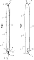
figures 5 et 6 représentent schématiquement la structure générale d'un ballonnet gonflable à usage médical, selon un autre mode de réalisation de l'invention, avant et après gonflage. - Le ballonnet gonflable 10 à usage médical représenté schématiquement sur la
figure 1 comporte un corps de ballonnet 12 dont la paroi 14 est en matériau souple gonflable, par exemple en silicone ou tout matériau équivalent présentant ces propriétés. Il est destiné à être inséré dégonflé dans une cavité de corps humain ou animal puis gonflé à l'intérieur de cette cavité en vue de faire pression contre elle. Il est de forme générale allongée, présentant une extrémité proximale 16 de gonflage et une extrémité distale 18 de positionnement en fond de cavité. L'extérieur de la paroi 14 est avantageusement enduit d'un produit glissant et non agressif pour les tissus biologiques de la cavité. - L'extrémité proximale 16 comporte un support rigide 20 qui présente une première ouverture et un embout de gonflage 22 menant à cette première ouverture. Cet embout 22 facilite l'introduction d'une seringue pour gonfler le corps de ballonnet 12 sous pression à l'aide d'un fluide tel que de l'air, de l'eau gélifiée, ou tout autre fluide approprié. Il peut être muni d'une valve, ou de tout système approprié pour le gonflage, de façon à permettre une injection ou une aspiration de fluide sans qu'il n'y ait de fuites lorsque l'on enlève la seringue ou le dispositif de gonflage.
- Le support rigide 20 présente en outre une seconde ouverture 24 destinée à l'introduction d'un endoscope dans le corps de ballonnet 12. Cette seconde ouverture 24 se présente par exemple sous la forme d'une valve ou de tout système permettant l'introduction d'un endoscope tout en empêchant toute sortie de fluide introduit dans le corps de ballonnet 12.
- Dans ce cas, il est avantageux, voire nécessaire que le fluide soit le plus transparent ou translucide possible pour une meilleure observation de l'environnement par l'endoscope à l'intérieur du ballonnet 10.
- Dans ce cas également, le ballonnet 10 comporte en outre une chaussette allongée 26 s'étendant à l'intérieur du corps de ballonnet 12 et présentant une extrémité distale fermée 28 non solidaire de la paroi 14 du corps de ballonnet 12. Une chaussette allongée doit être comprise comme un capuchon allongé, de forme complémentaire à celle de l'endoscope, à l'intérieur duquel débouche la seconde ouverture 24. Elle permet l'introduction de l'endoscope sans contact de ce dernier avec le fluide présent dans le corps de ballonnet 12. Elle est avantageusement formée dans un matériau souple éventuellement élastique, par exemple en silicone ou tout matériau de même nature.
- Conformément à l'invention, la paroi 14 du corps de ballonnet 12 présente localement une portion allongée 30, dite semelle, de plus forte rigidité que le reste de la paroi 14, cette semelle 30 s'étendant de l'extrémité proximale 16 jusqu'à l'extrémité distale 18. Elle forme la base du corps de ballonnet 12, facilitant l'introduction et le maintien du ballonnet 10 dans la cavité souhaitée même lorsque celui-ci est dégonflé. Par ailleurs, elle remplit une fonction de guide lors du gonflage du ballonnet 10, en lui donnant une direction précontrainte.
- En pratique la semelle 30 peut être une pièce rapportée contre la paroi 14 du corps de ballonnet 12, constituée de tout matériau assurant la fonction de rigidité voulue. Ce matériau peut être choisi de façon non limitative parmi des polymères tels que du polychlorure de vinyle, du polysiloxane, du polyuréthane, du polycarbonate polyéthylène, du polyméthacrylate de méthyle, du polytéréphtalate d'éthylène, ou parmi des polymères fluorés tels que du polytétrafluoroéthylène ou du polychlorotrifluoroéthylène. De façon alternative, elle peut être venue de matière avec le reste de la paroi 14 du corps de ballonnet 12, mais elle présente alors une épaisseur sensiblement supérieure au reste de cette paroi 14 pour augmenter sa rigidité.
- Comme illustré sur la
figure 2 , le ballonnet 10 peut être conçu pour un usage en otorhinolaryngologie. Dans ce cas, la paroi 14 du corps de ballonnet 12 peut être préformée pour épouser les formes intérieures d'une cavité nasale de corps humain ou animal en conformation gonflée. - La
figure 3 illustre le positionnement du ballonnet 10 desfigures 1 et 2 dans une cavité nasale 32, en conformation dégonflée. Grâce à la semelle 30 de rigidité supérieure au reste de la paroi 14 du corps de ballonnet 12, le ballonnet 10 est facilement introduit dans la cavité nasale 32. Une fois positionné, un fluide est introduit par l'embout 22 dans le corps de ballonnet 12 à l'aide d'une seringue 34. En procédant de la sorte, la pression à l'intérieur du corps de ballonnet est facilement contrôlée. - Cela permet le gonflage du ballonnet 10 jusqu'à obtention du résultat illustré sur la
figure 4 selon lequel le corps de ballonnet 12 occupe tout l'espace intérieur de la cavité nasale 32 en épousant la forme de ses parois. - Selon un autre mode de réalisation illustré en coupe sur la
figure 5 , et en reprenant les mêmes références que précédemment pour les éléments inchangés, le ballonnet 10 comporte en outre une tige rigide 36 d'introduction amovible s'étendant vers l'extérieur dans le prolongement de l'embout 22. Cette tige rigide 36 permet de faciliter l'installation du ballonnet 10 dans la cavité et peut être rompue ou retirée lorsque cette installation est correctement réalisée. Le ballonnet 10 peut être gonflé à l'aide de la seringue 34 avant ou après cette manoeuvre. - Le ballonnet 10 de cet autre mode de réalisation comporte en outre un fil rigide amovible 38 de mise en place, s'étendant en renforcement de la semelle 30 le long de ou dans cette dernière. Il est par exemple conçu en alliage de nickel-titane, ce matériau possédant des propriétés intéressantes de mémoire de forme et d'élasticité.
- Enfin, le ballonnet 10 de cet autre mode de réalisation comporte un renfort 40 en extrémité distale 18 dans le prolongement de la semelle 30. Ce renfort distal 40 présente, comme la semelle 30, une rigidité supérieure au reste de la paroi 14 du corps de ballonnet 12 et est conformé, par exemple selon un angle proche de 90° par rapport à la semelle 30, de manière à empêcher, en coopération avec cette dernière, tout allongement du ballonnet 10 lors de son gonflage. Il peut concrètement être constitué d'une pièce rapportée à l'extrémité distale de la semelle 30, constituée de tout matériau assurant la fonction de rigidité voulue. Ce matériau peut être choisi de façon non limitative parmi des polymères tels que du polychlorure de vinyle, du polysiloxane, du polyuréthane, du polycarbonate polyéthylène, du polyméthacrylate de méthyle, du polytéréphtalate d'éthylène, ou parmi des polymères fluorés tels que du polytétrafluoroéthylène ou du polychlorotrifluoroéthylène.
- Le ballonnet 10 de cet autre mode de réalisation est représenté en conformation dégonflée sur la
figure 5 et en conformation gonflée, avec retrait de la tige rigide 36 et du fil rigide amovible 38, sur lafigure 6 . - Il apparaît clairement qu'un ballonnet gonflable à usage médical tel que celui décrit précédemment permet une introduction et un positionnement aisés dans une cavité souhaitée de corps humain ou animal.
- Compte tenu de sa structure simple, il est de conception et fabrication aisées, de sorte qu'il peut être à utilisation unique puis jeté.
- Il est particulièrement adapté à des opérations médicales de chirurgies otorhinolaryngologiques, cervico-faciales ou neurologiques. Il peut aussi s'utiliser dans d'autres opérations chirurgicales, notamment en orthopédie ou chirurgie digestive. Sans même parler de chirurgie, il peut aussi s'utiliser en tant que simple dispositif de compression pour traiter toutes sortes d'épistaxis ou saignements de fosses nasales, de tels saignements se produisant par exemple couramment en consultation.
- On notera par ailleurs que l'invention n'est pas limitée aux modes de réalisation décrits précédemment.
- En particulier, les formes de la semelle 30 et du renfort distal 40 peuvent être adaptées à toutes les applications souhaitées. Elles sont donc potentiellement très diverses.
- Il apparaîtra plus généralement à l'homme de l'art que diverses modifications peuvent être apportées aux modes de réalisation décrits ci-dessus, à la lumière de l'enseignement qui vient de lui être divulgué. Dans les revendications qui suivent, les termes utilisés ne doivent pas être interprétés comme limitant les revendications aux modes de réalisation exposés dans la présente description.
Claims (7)
- Ballonnet gonflable (10) à usage médical, destiné à être inséré dégonflé dans une cavité de corps humain ou animal puis gonflé à l'intérieur de cette cavité en vue de faire pression contre elle, comportant :- un corps de ballonnet (12) dont la paroi (14) est en matériau souple gonflable, de forme générale allongée présentant une extrémité proximale (16) de gonflage et une extrémité distale (18) de positionnement en fond de cavité, la paroi (14) présentant en outre localement une portion allongée (30), dite semelle, de plus forte rigidité que le reste de la paroi (14), cette semelle s'étendant de l'extrémité proximale (16) jusqu'à l'extrémité distale (18),caractérisé en ce que l'ouverture (24) pour endoscope débouche à l'intérieur du corps de ballonnet (12) sur l'intérieur d'une chaussette allongée (26) présentant une extrémité distale fermée (28) non solidaire de la paroi (14) du corps de ballonnet (12).- une ouverture de gonflage (22) formée dans l'extrémité proximale (16), pour l'introduction d'un fluide dans le corps de ballonnet (12) de manière à le gonfler sous pression, et- une ouverture (24) pour endoscope en outre disposée dans l'extrémité proximale (16), cette ouverture (24) pour endoscope étant destinée à l'introduction d'un endoscope dans le corps de ballonnet (12),
- Ballonnet gonflable (10) à usage médical selon la revendication 1, dans lequel la semelle (30) est une pièce rapportée contre la paroi (14) du corps de ballonnet (12).
- Ballonnet gonflable (10) à usage médical selon la revendication 1, dans lequel la semelle (30) est venue de matière avec le reste de la paroi (14) du corps de ballonnet (12) mais présente une épaisseur sensiblement supérieure au reste de cette paroi (14).
- Ballonnet gonflable (10) à usage médical selon l'une quelconque des revendications 1 à 3, comportant en outre un renfort (40) en extrémité distale dans le prolongement de la semelle (30), ce renfort distal (40) présentant également une rigidité supérieure au reste de la paroi (14) du corps de ballonnet (12) et étant conformé de manière à empêcher, en coopération avec la semelle (30), tout allongement du ballonnet (10) lors de son gonflage.
- Ballonnet gonflable (10) à usage médical selon l'une quelconque des revendications 1 à 4, dans lequel l'ouverture (24) pour endoscope comporte une valve permettant l'introduction d'un endoscope tout en empêchant toute sortie de fluide.
- Ballonnet gonflable (10) à usage médical selon l'une quelconque des revendications 1 à 5, à utilisation en otorhinolaryngologie, dans lequel le corps de ballonnet (12) est préformé pour épouser les formes intérieures d'une cavité nasale (32) de corps humain ou animal lorsqu'il est gonflé.
- Ballonnet gonflable (10) à usage médical selon l'une quelconque des revendications 1 à 6, comportant en outre une tige (36) d'introduction amovible s'étendant vers l'extérieur dans le prolongement d'un embout de l'ouverture de gonflage (22) et un fil amovible (38) de mise en place s'étendant le long de la semelle (30) ou dans cette dernière.
Applications Claiming Priority (2)
| Application Number | Priority Date | Filing Date | Title |
|---|---|---|---|
| FR1559917A FR3042401A1 (fr) | 2015-10-16 | 2015-10-16 | Ballonnet gonflable a usage medical |
| PCT/FR2016/052661 WO2017064437A1 (fr) | 2015-10-16 | 2016-10-14 | Ballonnet gonflable à usage médical |
Publications (2)
| Publication Number | Publication Date |
|---|---|
| EP3361962A1 EP3361962A1 (fr) | 2018-08-22 |
| EP3361962B1 true EP3361962B1 (fr) | 2019-12-25 |
Family
ID=54848775
Family Applications (1)
| Application Number | Title | Priority Date | Filing Date |
|---|---|---|---|
| EP16806211.5A Active EP3361962B1 (fr) | 2015-10-16 | 2016-10-14 | Ballonnet gonflable à usage médical |
Country Status (7)
| Country | Link |
|---|---|
| US (1) | US10687838B2 (fr) |
| EP (1) | EP3361962B1 (fr) |
| JP (1) | JP6783315B2 (fr) |
| CN (1) | CN108697426B (fr) |
| ES (1) | ES2776648T3 (fr) |
| FR (1) | FR3042401A1 (fr) |
| WO (1) | WO2017064437A1 (fr) |
Families Citing this family (5)
| Publication number | Priority date | Publication date | Assignee | Title |
|---|---|---|---|---|
| FR3069771B1 (fr) * | 2017-08-03 | 2022-12-30 | Dianosic | Ballonnet gonflable a usage medical |
| CN110292414A (zh) * | 2019-06-01 | 2019-10-01 | 昆明医科大学第一附属医院 | 一种内镜经鼻腔微创手术用鼻腔支架 |
| CN110897671A (zh) * | 2019-12-20 | 2020-03-24 | 中国人民解放军陆军特色医学中心 | 可通气的鼻腔止血装置 |
| US11224436B2 (en) * | 2020-05-21 | 2022-01-18 | Cesar Munoz | Hemorrhage control device |
| WO2026089559A1 (fr) * | 2024-10-25 | 2026-04-30 | 가톨릭대학교 산학협력단 | Dispositif de compression de site chirurgical comprenant un tube d'écoulement d'air |
Family Cites Families (17)
| Publication number | Priority date | Publication date | Assignee | Title |
|---|---|---|---|---|
| US2265387A (en) | 1940-03-11 | 1941-12-09 | John H Mcmillin | Nasal pack |
| US3516407A (en) | 1968-04-25 | 1970-06-23 | Santo L Ruggero | Inflatable intranasal tampon |
| US3570494A (en) * | 1968-12-16 | 1971-03-16 | George H Gottschalk | Nasal tampon |
| US5139510A (en) | 1991-02-22 | 1992-08-18 | Xomed-Treace Inc. | Nasal packing device |
| GB9118670D0 (en) * | 1991-08-30 | 1991-10-16 | Mcnicholas Thomas A | Surgical devices and uses thereof |
| US5569183A (en) * | 1994-06-01 | 1996-10-29 | Archimedes Surgical, Inc. | Method for performing surgery around a viewing space in the interior of the body |
| WO1996039218A1 (fr) * | 1995-06-06 | 1996-12-12 | Hogle Gregory A | Dispositif gonflable de tamponnement nasal |
| US5993473A (en) * | 1997-11-19 | 1999-11-30 | Chan; Yung C. | Expandable body device for the gastric cavity and method |
| DE29923582U1 (de) * | 1999-07-08 | 2000-12-14 | Hintersdorf, Steffen, 09126 Chemnitz | Vorrichtung zur Anwendung innerhalb des Nasenbereichs, insbesondere zum Einsetzen in die Nasenhöhlen |
| AUPR785001A0 (en) * | 2001-09-21 | 2001-10-18 | Kleiner, Daniel E. | Tamponade apparatus and method of using same |
| US7112195B2 (en) * | 2003-04-21 | 2006-09-26 | Cynosure, Inc. | Esophageal lesion treatment method |
| JP5135816B2 (ja) * | 2007-02-09 | 2013-02-06 | 日本ゼオン株式会社 | 結石除去用バルーンカテーテル |
| ES2874194T3 (es) * | 2009-12-16 | 2021-11-04 | Boston Scient Scimed Inc | Disposiciones para realizar una estructura anatómica endoluminal |
| US9623213B2 (en) * | 2013-03-15 | 2017-04-18 | Acclarent, Inc. | Uncinate process support for ethmoid infundibulum illumination |
| CN103203058A (zh) * | 2013-04-12 | 2013-07-17 | 浙江曙光科技有限公司 | 多腔道一体式可插内窥镜的喉罩 |
| CN103393387A (zh) * | 2013-08-09 | 2013-11-20 | 广州宝胆医疗器械科技有限公司 | 医用器械鞘 |
| CN103767754A (zh) * | 2014-01-24 | 2014-05-07 | 东莞麦可龙医疗科技有限公司 | 可视性产后止血器械及其制造方法 |
-
2015
- 2015-10-16 FR FR1559917A patent/FR3042401A1/fr not_active Withdrawn
-
2016
- 2016-10-14 JP JP2018538951A patent/JP6783315B2/ja active Active
- 2016-10-14 WO PCT/FR2016/052661 patent/WO2017064437A1/fr not_active Ceased
- 2016-10-14 EP EP16806211.5A patent/EP3361962B1/fr active Active
- 2016-10-14 ES ES16806211T patent/ES2776648T3/es active Active
- 2016-10-14 US US15/768,738 patent/US10687838B2/en active Active
- 2016-10-14 CN CN201680067093.7A patent/CN108697426B/zh active Active
Non-Patent Citations (1)
| Title |
|---|
| None * |
Also Published As
| Publication number | Publication date |
|---|---|
| CN108697426B (zh) | 2021-03-02 |
| FR3042401A1 (fr) | 2017-04-21 |
| EP3361962A1 (fr) | 2018-08-22 |
| CN108697426A (zh) | 2018-10-23 |
| ES2776648T3 (es) | 2020-07-31 |
| JP2018531136A (ja) | 2018-10-25 |
| WO2017064437A1 (fr) | 2017-04-20 |
| US20180310947A1 (en) | 2018-11-01 |
| US10687838B2 (en) | 2020-06-23 |
| JP6783315B2 (ja) | 2020-11-11 |
Similar Documents
| Publication | Publication Date | Title |
|---|---|---|
| EP1027091B1 (fr) | Catheter universel | |
| EP0605351B1 (fr) | Instrument, destiné à l'extraction des tronçons veineux | |
| EP0755281B1 (fr) | Catheter de dilatation a echange rapide | |
| WO2017064437A1 (fr) | Ballonnet gonflable à usage médical | |
| EP1865886B1 (fr) | Necessaire destine a etre implante dans un conduit de circulation du sang, et endoprothese tubulaire associee | |
| EP1315458B1 (fr) | Dispositif d'occlusion vasculaire et appareil d'utilisation | |
| EP1708656B1 (fr) | Ceinture gastrique | |
| EP1108400A1 (fr) | Dispositif de fixation amovible d'une prothèse dans un conduit d'un organisme vivant | |
| FR2668695A1 (fr) | Instrument chirurgical endoscopique pour le deplacement de tissus ou organes. | |
| FR2781380A1 (fr) | Bague pour lier un tube souple deformable et une tige resistante a l'ecrasement, et ensemble medical muni d'une telle bague | |
| CA2127112A1 (fr) | Catheter de dilatation | |
| EP0327431A1 (fr) | Sonde destinée à être introduite à l'intérieur d'un corps vivant | |
| FR2941617A1 (fr) | Ballon intra-gastrique. | |
| EP4559419A2 (fr) | Catheter bi-fonctionnel a deux gaines coulissantes | |
| EP1583580A2 (fr) | Passe-guide | |
| EP2436343B1 (fr) | Dispositif de placement pour instrument de traitement médical tubulaire, et extrémité antérieure d'un dispositif de placement d'un instrument de traitement médical tubulaire | |
| EP3661409B1 (fr) | Ballonnet gonflable a usage médical | |
| EP0748241A1 (fr) | Catheter de dilatation a echange rapide | |
| CA2656345A1 (fr) | Ceinture gastrique preformee en « c » | |
| FR3038829A1 (fr) | Implant penien notamment pour transsexuel femme vers homme | |
| EP0266469B1 (fr) | Sonde oesophagienne | |
| EP0974375B1 (fr) | Dispositif à ballonnet à diamètre nominal ajustable | |
| CH661665A5 (en) | Device for fitting an oesophageal prosthesis | |
| EP3367937A1 (fr) | Dispositif intra-utérin récupérable | |
| EP2398539B1 (fr) | Canule trachéale |
Legal Events
| Date | Code | Title | Description |
|---|---|---|---|
| STAA | Information on the status of an ep patent application or granted ep patent |
Free format text: STATUS: UNKNOWN |
|
| STAA | Information on the status of an ep patent application or granted ep patent |
Free format text: STATUS: THE INTERNATIONAL PUBLICATION HAS BEEN MADE |
|
| PUAI | Public reference made under article 153(3) epc to a published international application that has entered the european phase |
Free format text: ORIGINAL CODE: 0009012 |
|
| STAA | Information on the status of an ep patent application or granted ep patent |
Free format text: STATUS: REQUEST FOR EXAMINATION WAS MADE |
|
| 17P | Request for examination filed |
Effective date: 20180416 |
|
| AK | Designated contracting states |
Kind code of ref document: A1 Designated state(s): AL AT BE BG CH CY CZ DE DK EE ES FI FR GB GR HR HU IE IS IT LI LT LU LV MC MK MT NL NO PL PT RO RS SE SI SK SM TR |
|
| AX | Request for extension of the european patent |
Extension state: BA ME |
|
| DAV | Request for validation of the european patent (deleted) | ||
| DAX | Request for extension of the european patent (deleted) | ||
| GRAP | Despatch of communication of intention to grant a patent |
Free format text: ORIGINAL CODE: EPIDOSNIGR1 |
|
| STAA | Information on the status of an ep patent application or granted ep patent |
Free format text: STATUS: GRANT OF PATENT IS INTENDED |
|
| INTG | Intention to grant announced |
Effective date: 20190814 |
|
| GRAS | Grant fee paid |
Free format text: ORIGINAL CODE: EPIDOSNIGR3 |
|
| GRAA | (expected) grant |
Free format text: ORIGINAL CODE: 0009210 |
|
| STAA | Information on the status of an ep patent application or granted ep patent |
Free format text: STATUS: THE PATENT HAS BEEN GRANTED |
|
| AK | Designated contracting states |
Kind code of ref document: B1 Designated state(s): AL AT BE BG CH CY CZ DE DK EE ES FI FR GB GR HR HU IE IS IT LI LT LU LV MC MK MT NL NO PL PT RO RS SE SI SK SM TR |
|
| REG | Reference to a national code |
Ref country code: GB Ref legal event code: FG4D Free format text: NOT ENGLISH |
|
| REG | Reference to a national code |
Ref country code: CH Ref legal event code: EP |
|
| REG | Reference to a national code |
Ref country code: DE Ref legal event code: R096 Ref document number: 602016027022 Country of ref document: DE |
|
| REG | Reference to a national code |
Ref country code: AT Ref legal event code: REF Ref document number: 1216252 Country of ref document: AT Kind code of ref document: T Effective date: 20200115 |
|
| REG | Reference to a national code |
Ref country code: IE Ref legal event code: FG4D Free format text: LANGUAGE OF EP DOCUMENT: FRENCH |
|
| REG | Reference to a national code |
Ref country code: NL Ref legal event code: MP Effective date: 20191225 |
|
| PG25 | Lapsed in a contracting state [announced via postgrant information from national office to epo] |
Ref country code: LV Free format text: LAPSE BECAUSE OF FAILURE TO SUBMIT A TRANSLATION OF THE DESCRIPTION OR TO PAY THE FEE WITHIN THE PRESCRIBED TIME-LIMIT Effective date: 20191225 Ref country code: SE Free format text: LAPSE BECAUSE OF FAILURE TO SUBMIT A TRANSLATION OF THE DESCRIPTION OR TO PAY THE FEE WITHIN THE PRESCRIBED TIME-LIMIT Effective date: 20191225 Ref country code: BG Free format text: LAPSE BECAUSE OF FAILURE TO SUBMIT A TRANSLATION OF THE DESCRIPTION OR TO PAY THE FEE WITHIN THE PRESCRIBED TIME-LIMIT Effective date: 20200325 Ref country code: FI Free format text: LAPSE BECAUSE OF FAILURE TO SUBMIT A TRANSLATION OF THE DESCRIPTION OR TO PAY THE FEE WITHIN THE PRESCRIBED TIME-LIMIT Effective date: 20191225 Ref country code: NO Free format text: LAPSE BECAUSE OF FAILURE TO SUBMIT A TRANSLATION OF THE DESCRIPTION OR TO PAY THE FEE WITHIN THE PRESCRIBED TIME-LIMIT Effective date: 20200325 Ref country code: GR Free format text: LAPSE BECAUSE OF FAILURE TO SUBMIT A TRANSLATION OF THE DESCRIPTION OR TO PAY THE FEE WITHIN THE PRESCRIBED TIME-LIMIT Effective date: 20200326 Ref country code: LT Free format text: LAPSE BECAUSE OF FAILURE TO SUBMIT A TRANSLATION OF THE DESCRIPTION OR TO PAY THE FEE WITHIN THE PRESCRIBED TIME-LIMIT Effective date: 20191225 |
|
| REG | Reference to a national code |
Ref country code: LT Ref legal event code: MG4D |
|
| PG25 | Lapsed in a contracting state [announced via postgrant information from national office to epo] |
Ref country code: HR Free format text: LAPSE BECAUSE OF FAILURE TO SUBMIT A TRANSLATION OF THE DESCRIPTION OR TO PAY THE FEE WITHIN THE PRESCRIBED TIME-LIMIT Effective date: 20191225 Ref country code: RS Free format text: LAPSE BECAUSE OF FAILURE TO SUBMIT A TRANSLATION OF THE DESCRIPTION OR TO PAY THE FEE WITHIN THE PRESCRIBED TIME-LIMIT Effective date: 20191225 |
|
| PG25 | Lapsed in a contracting state [announced via postgrant information from national office to epo] |
Ref country code: AL Free format text: LAPSE BECAUSE OF FAILURE TO SUBMIT A TRANSLATION OF THE DESCRIPTION OR TO PAY THE FEE WITHIN THE PRESCRIBED TIME-LIMIT Effective date: 20191225 |
|
| PG25 | Lapsed in a contracting state [announced via postgrant information from national office to epo] |
Ref country code: RO Free format text: LAPSE BECAUSE OF FAILURE TO SUBMIT A TRANSLATION OF THE DESCRIPTION OR TO PAY THE FEE WITHIN THE PRESCRIBED TIME-LIMIT Effective date: 20191225 Ref country code: CZ Free format text: LAPSE BECAUSE OF FAILURE TO SUBMIT A TRANSLATION OF THE DESCRIPTION OR TO PAY THE FEE WITHIN THE PRESCRIBED TIME-LIMIT Effective date: 20191225 Ref country code: NL Free format text: LAPSE BECAUSE OF FAILURE TO SUBMIT A TRANSLATION OF THE DESCRIPTION OR TO PAY THE FEE WITHIN THE PRESCRIBED TIME-LIMIT Effective date: 20191225 Ref country code: PT Free format text: LAPSE BECAUSE OF FAILURE TO SUBMIT A TRANSLATION OF THE DESCRIPTION OR TO PAY THE FEE WITHIN THE PRESCRIBED TIME-LIMIT Effective date: 20200520 Ref country code: EE Free format text: LAPSE BECAUSE OF FAILURE TO SUBMIT A TRANSLATION OF THE DESCRIPTION OR TO PAY THE FEE WITHIN THE PRESCRIBED TIME-LIMIT Effective date: 20191225 |
|
| REG | Reference to a national code |
Ref country code: ES Ref legal event code: FG2A Ref document number: 2776648 Country of ref document: ES Kind code of ref document: T3 Effective date: 20200731 |
|
| PG25 | Lapsed in a contracting state [announced via postgrant information from national office to epo] |
Ref country code: SM Free format text: LAPSE BECAUSE OF FAILURE TO SUBMIT A TRANSLATION OF THE DESCRIPTION OR TO PAY THE FEE WITHIN THE PRESCRIBED TIME-LIMIT Effective date: 20191225 Ref country code: IS Free format text: LAPSE BECAUSE OF FAILURE TO SUBMIT A TRANSLATION OF THE DESCRIPTION OR TO PAY THE FEE WITHIN THE PRESCRIBED TIME-LIMIT Effective date: 20200425 Ref country code: SK Free format text: LAPSE BECAUSE OF FAILURE TO SUBMIT A TRANSLATION OF THE DESCRIPTION OR TO PAY THE FEE WITHIN THE PRESCRIBED TIME-LIMIT Effective date: 20191225 |
|
| REG | Reference to a national code |
Ref country code: DE Ref legal event code: R097 Ref document number: 602016027022 Country of ref document: DE |
|
| PG25 | Lapsed in a contracting state [announced via postgrant information from national office to epo] |
Ref country code: DK Free format text: LAPSE BECAUSE OF FAILURE TO SUBMIT A TRANSLATION OF THE DESCRIPTION OR TO PAY THE FEE WITHIN THE PRESCRIBED TIME-LIMIT Effective date: 20191225 |
|
| PLBE | No opposition filed within time limit |
Free format text: ORIGINAL CODE: 0009261 |
|
| STAA | Information on the status of an ep patent application or granted ep patent |
Free format text: STATUS: NO OPPOSITION FILED WITHIN TIME LIMIT |
|
| REG | Reference to a national code |
Ref country code: AT Ref legal event code: MK05 Ref document number: 1216252 Country of ref document: AT Kind code of ref document: T Effective date: 20191225 |
|
| PG25 | Lapsed in a contracting state [announced via postgrant information from national office to epo] |
Ref country code: SI Free format text: LAPSE BECAUSE OF FAILURE TO SUBMIT A TRANSLATION OF THE DESCRIPTION OR TO PAY THE FEE WITHIN THE PRESCRIBED TIME-LIMIT Effective date: 20191225 |
|
| 26N | No opposition filed |
Effective date: 20200928 |
|
| PG25 | Lapsed in a contracting state [announced via postgrant information from national office to epo] |
Ref country code: AT Free format text: LAPSE BECAUSE OF FAILURE TO SUBMIT A TRANSLATION OF THE DESCRIPTION OR TO PAY THE FEE WITHIN THE PRESCRIBED TIME-LIMIT Effective date: 20191225 |
|
| PG25 | Lapsed in a contracting state [announced via postgrant information from national office to epo] |
Ref country code: PL Free format text: LAPSE BECAUSE OF FAILURE TO SUBMIT A TRANSLATION OF THE DESCRIPTION OR TO PAY THE FEE WITHIN THE PRESCRIBED TIME-LIMIT Effective date: 20191225 |
|
| PG25 | Lapsed in a contracting state [announced via postgrant information from national office to epo] |
Ref country code: TR Free format text: LAPSE BECAUSE OF FAILURE TO SUBMIT A TRANSLATION OF THE DESCRIPTION OR TO PAY THE FEE WITHIN THE PRESCRIBED TIME-LIMIT Effective date: 20191225 Ref country code: MT Free format text: LAPSE BECAUSE OF FAILURE TO SUBMIT A TRANSLATION OF THE DESCRIPTION OR TO PAY THE FEE WITHIN THE PRESCRIBED TIME-LIMIT Effective date: 20191225 Ref country code: CY Free format text: LAPSE BECAUSE OF FAILURE TO SUBMIT A TRANSLATION OF THE DESCRIPTION OR TO PAY THE FEE WITHIN THE PRESCRIBED TIME-LIMIT Effective date: 20191225 |
|
| PG25 | Lapsed in a contracting state [announced via postgrant information from national office to epo] |
Ref country code: MK Free format text: LAPSE BECAUSE OF FAILURE TO SUBMIT A TRANSLATION OF THE DESCRIPTION OR TO PAY THE FEE WITHIN THE PRESCRIBED TIME-LIMIT Effective date: 20191225 |
|
| REG | Reference to a national code |
Ref country code: CH Ref legal event code: U11 Free format text: ST27 STATUS EVENT CODE: U-0-0-U10-U11 (AS PROVIDED BY THE NATIONAL OFFICE) Effective date: 20251101 |
|
| PGFP | Annual fee paid to national office [announced via postgrant information from national office to epo] |
Ref country code: LU Payment date: 20251022 Year of fee payment: 10 |
|
| PGFP | Annual fee paid to national office [announced via postgrant information from national office to epo] |
Ref country code: DE Payment date: 20251020 Year of fee payment: 10 |
|
| PGFP | Annual fee paid to national office [announced via postgrant information from national office to epo] |
Ref country code: GB Payment date: 20251024 Year of fee payment: 10 |
|
| PGFP | Annual fee paid to national office [announced via postgrant information from national office to epo] |
Ref country code: MC Payment date: 20251022 Year of fee payment: 10 |
|
| PGFP | Annual fee paid to national office [announced via postgrant information from national office to epo] |
Ref country code: IT Payment date: 20251031 Year of fee payment: 10 |
|
| PGFP | Annual fee paid to national office [announced via postgrant information from national office to epo] |
Ref country code: FR Payment date: 20251027 Year of fee payment: 10 |
|
| PGFP | Annual fee paid to national office [announced via postgrant information from national office to epo] |
Ref country code: BE Payment date: 20251022 Year of fee payment: 10 |
|
| PGFP | Annual fee paid to national office [announced via postgrant information from national office to epo] |
Ref country code: CH Payment date: 20251101 Year of fee payment: 10 |
|
| PGFP | Annual fee paid to national office [announced via postgrant information from national office to epo] |
Ref country code: IE Payment date: 20251021 Year of fee payment: 10 |
|
| PGFP | Annual fee paid to national office [announced via postgrant information from national office to epo] |
Ref country code: ES Payment date: 20251114 Year of fee payment: 10 |