EP3360698A1 - Non-pneumatic tire - Google Patents
Non-pneumatic tire Download PDFInfo
- Publication number
- EP3360698A1 EP3360698A1 EP16853559.9A EP16853559A EP3360698A1 EP 3360698 A1 EP3360698 A1 EP 3360698A1 EP 16853559 A EP16853559 A EP 16853559A EP 3360698 A1 EP3360698 A1 EP 3360698A1
- Authority
- EP
- European Patent Office
- Prior art keywords
- point
- straight line
- end portion
- tire
- coupling member
- Prior art date
- Legal status (The legal status is an assumption and is not a legal conclusion. Google has not performed a legal analysis and makes no representation as to the accuracy of the status listed.)
- Granted
Links
- 230000008878 coupling Effects 0.000 claims abstract description 96
- 238000010168 coupling process Methods 0.000 claims abstract description 96
- 238000005859 coupling reaction Methods 0.000 claims abstract description 96
- 230000007423 decrease Effects 0.000 claims description 5
- 229920002725 thermoplastic elastomer Polymers 0.000 description 13
- 239000000463 material Substances 0.000 description 10
- 229920005989 resin Polymers 0.000 description 6
- 239000011347 resin Substances 0.000 description 6
- 230000000052 comparative effect Effects 0.000 description 5
- 238000001746 injection moulding Methods 0.000 description 5
- 230000014509 gene expression Effects 0.000 description 3
- 239000000203 mixture Substances 0.000 description 3
- 238000000465 moulding Methods 0.000 description 3
- 238000012360 testing method Methods 0.000 description 3
- 229920005992 thermoplastic resin Polymers 0.000 description 3
- 238000012795 verification Methods 0.000 description 3
- PPBRXRYQALVLMV-UHFFFAOYSA-N Styrene Chemical compound C=CC1=CC=CC=C1 PPBRXRYQALVLMV-UHFFFAOYSA-N 0.000 description 2
- 230000000694 effects Effects 0.000 description 2
- 229920001971 elastomer Polymers 0.000 description 2
- 239000007769 metal material Substances 0.000 description 2
- 229920003002 synthetic resin Polymers 0.000 description 2
- 239000000057 synthetic resin Substances 0.000 description 2
- 239000012815 thermoplastic material Substances 0.000 description 2
- 229920002803 thermoplastic polyurethane Polymers 0.000 description 2
- 239000004636 vulcanized rubber Substances 0.000 description 2
- 229910000838 Al alloy Inorganic materials 0.000 description 1
- JOYRKODLDBILNP-UHFFFAOYSA-N Ethyl urethane Chemical compound CCOC(N)=O JOYRKODLDBILNP-UHFFFAOYSA-N 0.000 description 1
- 244000043261 Hevea brasiliensis Species 0.000 description 1
- BZHJMEDXRYGGRV-UHFFFAOYSA-N Vinyl chloride Chemical compound ClC=C BZHJMEDXRYGGRV-UHFFFAOYSA-N 0.000 description 1
- 239000000654 additive Substances 0.000 description 1
- 150000001336 alkenes Chemical class 0.000 description 1
- 150000001408 amides Chemical class 0.000 description 1
- 230000003712 anti-aging effect Effects 0.000 description 1
- 238000005266 casting Methods 0.000 description 1
- 239000003795 chemical substances by application Substances 0.000 description 1
- 239000000806 elastomer Substances 0.000 description 1
- 230000002708 enhancing effect Effects 0.000 description 1
- 150000002148 esters Chemical class 0.000 description 1
- 239000000945 filler Substances 0.000 description 1
- 238000007429 general method Methods 0.000 description 1
- 238000002347 injection Methods 0.000 description 1
- 239000007924 injection Substances 0.000 description 1
- 238000000034 method Methods 0.000 description 1
- 238000012986 modification Methods 0.000 description 1
- 230000004048 modification Effects 0.000 description 1
- 229920003052 natural elastomer Polymers 0.000 description 1
- 229920001194 natural rubber Polymers 0.000 description 1
- JRZJOMJEPLMPRA-UHFFFAOYSA-N olefin Natural products CCCCCCCC=C JRZJOMJEPLMPRA-UHFFFAOYSA-N 0.000 description 1
- 239000000049 pigment Substances 0.000 description 1
- 239000004014 plasticizer Substances 0.000 description 1
- 229920006122 polyamide resin Polymers 0.000 description 1
- 229920005672 polyolefin resin Polymers 0.000 description 1
- 238000004088 simulation Methods 0.000 description 1
- 239000000243 solution Substances 0.000 description 1
Images

Classifications
-
- B—PERFORMING OPERATIONS; TRANSPORTING
- B60—VEHICLES IN GENERAL
- B60C—VEHICLE TYRES; TYRE INFLATION; TYRE CHANGING; CONNECTING VALVES TO INFLATABLE ELASTIC BODIES IN GENERAL; DEVICES OR ARRANGEMENTS RELATED TO TYRES
- B60C7/00—Non-inflatable or solid tyres
- B60C7/10—Non-inflatable or solid tyres characterised by means for increasing resiliency
- B60C7/14—Non-inflatable or solid tyres characterised by means for increasing resiliency using springs
- B60C7/146—Non-inflatable or solid tyres characterised by means for increasing resiliency using springs extending substantially radially, e.g. like spokes
-
- B—PERFORMING OPERATIONS; TRANSPORTING
- B60—VEHICLES IN GENERAL
- B60C—VEHICLE TYRES; TYRE INFLATION; TYRE CHANGING; CONNECTING VALVES TO INFLATABLE ELASTIC BODIES IN GENERAL; DEVICES OR ARRANGEMENTS RELATED TO TYRES
- B60C7/00—Non-inflatable or solid tyres
- B60C7/10—Non-inflatable or solid tyres characterised by means for increasing resiliency
- B60C7/14—Non-inflatable or solid tyres characterised by means for increasing resiliency using springs
-
- B—PERFORMING OPERATIONS; TRANSPORTING
- B60—VEHICLES IN GENERAL
- B60B—VEHICLE WHEELS; CASTORS; AXLES FOR WHEELS OR CASTORS; INCREASING WHEEL ADHESION
- B60B9/00—Wheels of high resiliency, e.g. with conical interacting pressure-surfaces
- B60B9/02—Wheels of high resiliency, e.g. with conical interacting pressure-surfaces using springs resiliently mounted bicycle rims
- B60B9/04—Wheels of high resiliency, e.g. with conical interacting pressure-surfaces using springs resiliently mounted bicycle rims in leaf form
-
- B—PERFORMING OPERATIONS; TRANSPORTING
- B60—VEHICLES IN GENERAL
- B60C—VEHICLE TYRES; TYRE INFLATION; TYRE CHANGING; CONNECTING VALVES TO INFLATABLE ELASTIC BODIES IN GENERAL; DEVICES OR ARRANGEMENTS RELATED TO TYRES
- B60C7/00—Non-inflatable or solid tyres
- B60C7/10—Non-inflatable or solid tyres characterised by means for increasing resiliency
- B60C7/14—Non-inflatable or solid tyres characterised by means for increasing resiliency using springs
- B60C7/143—Non-inflatable or solid tyres characterised by means for increasing resiliency using springs having a lateral extension disposed in a plane parallel to the wheel axis
-
- B—PERFORMING OPERATIONS; TRANSPORTING
- B60—VEHICLES IN GENERAL
- B60B—VEHICLE WHEELS; CASTORS; AXLES FOR WHEELS OR CASTORS; INCREASING WHEEL ADHESION
- B60B2200/00—Type of product being used or applied
- B60B2200/20—Furniture or medical appliances
- B60B2200/22—Chairs
-
- B—PERFORMING OPERATIONS; TRANSPORTING
- B60—VEHICLES IN GENERAL
- B60B—VEHICLE WHEELS; CASTORS; AXLES FOR WHEELS OR CASTORS; INCREASING WHEEL ADHESION
- B60B2900/00—Purpose of invention
- B60B2900/30—Increase in
- B60B2900/321—Lifetime
-
- B—PERFORMING OPERATIONS; TRANSPORTING
- B60—VEHICLES IN GENERAL
- B60B—VEHICLE WHEELS; CASTORS; AXLES FOR WHEELS OR CASTORS; INCREASING WHEEL ADHESION
- B60B9/00—Wheels of high resiliency, e.g. with conical interacting pressure-surfaces
Definitions
- the present invention relates to a non-pneumatic tire which does not need to be filled with pressurized air, when in use.
- the coupling body includes a plurality of coupling members disposed at intervals in a tire circumferential direction, opposite ends of each of the coupling members are respectively coupled to the attachment body and the outer cylindrical body, and a first end portion which is an outer end portion in the tire radial direction is positioned on one side in the tire circumferential direction of a second end portion which is an inner end portion in the tire radial direction.
- the present invention is made in consideration of the above-described circumstances, and an object of the present invention is to enhance durability.
- a non-pneumatic tire according to the present invention includes an attachment body attached to an axle, an outer cylindrical body which surrounds the attachment body from the outside in a tire radial direction, and a coupling body which couples the outer cylindrical body and the attachment body, in which the coupling body includes a plurality of coupling members disposed at intervals in a tire circumferential direction, opposite ends of each of the coupling members are respectively coupled to the attachment body and the outer cylindrical body, and a first end portion which is an outer end portion of the coupling member in the tire radial direction is positioned on one side in the tire circumferential direction of a second end portion which is an inner end portion in the tire radial direction, in which, in a tire side view when the non-pneumatic tire is viewed from a tire width direction, when a first point, a second point, a third point, a fourth point, and a fifth point are set in order from the first end portion side toward the second end portion side on a center line passing through a center in the tire circumferential direction
- a non-pneumatic tire 1 of the present embodiment includes an attachment body 11 attached to an axle (not shown), an outer cylindrical body 13 in a cylindrical shape which surrounds the attachment body 11 from the outside in a tire radial direction, a coupling body 14 which couples the attachment body 11 and the outer cylindrical body 13, and a cylindrical tread member 16 wrapped externally around the outer cylindrical body 13.
- the non-pneumatic tire 1 of the present embodiment may be employed in a small-sized vehicle traveling at a low speed such as a handle type electric wheelchair specified in Japanese Industrial Standard JIS T 9208, for example.
- the size of the non-pneumatic tire 1 is not particularly limited, but may be in a range of 3.00- 8 or the like, for example.
- the non-pneumatic tire 1 may be employed for passenger cars. The size in this case is not particularly limited, but may be 155/65R 13 or the like, for example.
- attachment body 11, the outer cylindrical body 13, and the tread member 16 are coaxially arranged on a common axis.
- this common axis is referred to as an axis O
- a direction along the axis O is referred to as a tire width direction
- a direction perpendicular to the axis O is referred to as a tire radial direction
- a direction of revolving around the axis O is referred to as a tire circumferential direction.
- center portions in the tire width direction of the attachment body 11, the outer cylindrical body 13, and the tread member 16 coincide with each other.
- the attachment body 11 includes a fitting cylinder portion 17 to which a distal end portion of the axle is fitted, an outer ring portion 18 which surrounds the fitting cylinder portion 17 from the outside in the tire radial direction, and a plurality of ribs 19 which couple the fitting cylinder portion 17 to the outer ring portion 18.
- the fitting cylinder portion 17, the outer ring portion 18, and the ribs 19 are integrally formed of a metal material such as an aluminum alloy, for example.
- the fitting cylinder portion 17 and the outer ring portion 18 are formed in a cylindrical shape and are coaxially arranged on the axis O.
- the plurality of ribs 19 are disposed at regular intervals in the tire circumferential direction, for example.
- a plurality of key groove portions (not shown) recessed toward the inside in the tire radial direction and configured to extend in the tire width direction are formed on an outer circumferential surface of the outer ring portion 18 at intervals in the tire circumferential direction.
- the key groove portions are open only on one side (outer side of the vehicle body) in the tire width direction and are closed on the other side (inside the vehicle body) in the tire width direction.
- An inner cylindrical body 12 in a cylindrical shape which is externally fitted to the outer ring portion 18 is provided on the attachment body 11.
- a ridge portion (not shown) protruding toward the inside in the tire radial direction and extending over the entire length in the tire width direction is formed on an inner circumferential surface of the inner cylindrical body 12.
- a plurality of ridge portions are formed on the inner circumferential surface of the inner cylindrical body 12 at intervals in the tire circumferential direction and respectively engaged with the key groove portions.
- the inner cylindrical body 12 is fixed to the attachment body 11 in a state in which the ridge portions are engaged with the key groove portions.
- the inner cylindrical body 12 is fixed to the attachment body 11 by screwing plates 28 from one side in the tire width direction at a position corresponding to the key groove portions in the outer ring portion 18.
- a plurality of coupling bodies 14 are arranged in a tire circumferential direction between the attachment body 11 and the outer cylindrical body 13, and each of the coupling bodies 14 includes a coupling member 15 which couples the attachment body 11 and the outer cylindrical body 13 in an elastically relatively displaceable manner.
- a plurality of coupling members 15 are disposed at intervals in the tire circumferential direction, opposite ends of each of the coupling members 15 are respectively coupled to the attachment body 11 and the outer cylindrical body 13, and a first end portion (outer end portion 15a) which is an outer end portion in the tire radial direction is positioned on one side in the tire circumferential direction of the second end portion (inner end portion 15b) which is an inner end portion in the tire radial direction.
- the coupling member 15 gradually extends toward the other side in the tire circumferential direction from the outside toward the inside in the tire radial direction.
- the coupling member 15 couples an outer circumferential surface side of the attachment body 11 to an inner circumferential surface side of the outer cylindrical body 13 in an elastically relatively displaceable manner.
- the coupling member 15 is an elastically deformable plate whose front and rear surfaces are directed in the tire circumferential direction.
- a plurality of coupling members 15 are disposed in the tire circumferential direction.
- the plurality of coupling members 15 are respectively disposed at positions rotationally symmetrical with respect to the axis O between the inner cylindrical body 12 and the outer cylindrical body 13. All the coupling members 15 have the same shape and the same size, and the width of the coupling members 15 in the tire width direction is smaller than the width of the outer cylindrical body 13 in the tire width direction. Adjacent coupling members 15 in the tire circumferential direction are not in contact with each other.
- a first end portion (outer end portion 15a) coupled to the outer cylindrical body 13 is positioned on one side in the tire circumferential direction of the second end portion (inner end portion 15b) coupled to the inner cylindrical body 12.
- a plurality of curved portions 15d to 15f which are curved in the tire circumferential direction are formed in the coupling member 15 at intermediate portions between the outer end portion 15a and the inner end portion 15b.
- the plurality of curved portions 15d to 15f are formed along an extending direction in which the coupling member 15 extends in a tire side view when the non-pneumatic tire 1 is viewed from the tire width direction.
- the plurality of curved portions 15d to 15f of the coupling member 15 are adjacent to each other in the above-described extending direction while having curvature directions opposite to each other.
- the plurality of curved portions 15d to 15f include a first curved portion 15d curved to protrude toward the other side in the tire circumferential direction, a second curved portion 15e positioned between the first curved portion 15d and the outer end portion 15a and curved to protrude toward one side in the tire circumferential direction, and a third curved portion 15f positioned between the first curved portion 15d and the inner end portion 15b and curved to protrude toward one side in the tire circumferential direction.
- inflection portions 15g and 15h are formed in the coupling member 15 at portions positioned between each of the curved portions 15d to 15f adjacent to each other in the extending direction of the coupling member 15.
- the above-described inner cylindrical body 12, the outer cylindrical body 13, and the plurality of coupling members 15 are integrally formed of a synthetic resin material, for example.
- the synthetic resin material may be, for example, a single resin material, a mixture containing two or more kinds of resin material, or a mixture containing one or more kinds of resin material and one or more kinds of elastomer, and furthermore, may include additives such as anti-aging agents, plasticizers, fillers, or pigments, for example.
- a unit in which the inner cylindrical body 12, the outer cylindrical body 13, and the coupling member 15 are integrally formed is referred to as a case body 31.
- the case body 31 can be integrally formed by injection molding, for example.
- the injection molding may include a general method of molding the entire case body 31 at once, insert molding in which the remaining portions other than insert parts are injection molded with some portions among the inner cylindrical body 12, the outer cylindrical body 13, and the coupling member 15 being provided as the insert parts, a so-called two-color molding, or the like.
- a plurality of protrusions formed on the inner cylindrical body 12 may be a gate portion.
- the inner cylindrical body 12, the outer cylindrical body 13, and the coupling member 15 may be formed of different materials, or may be formed of the same material.
- metal materials, resin materials, or the like are examples; however, resin materials, particularly thermoplastic resins, are preferable from the perspective of reducing weight.
- the tread member 16 is formed in a cylindrical shape and integrally covers an outer circumferential surface side of the outer cylindrical body 13 over the entire region. An inner circumferential surface of the tread member 16 is in close contact with the outer circumferential surface of the outer cylindrical body 13 over the entire region.
- the tread member 16 is formed of a natural rubber and/or a vulcanized rubber in which the rubber composition is vulcanized, a thermoplastic material, or the like, for example.
- thermoplastic material a thermoplastic elastomer, a thermoplastic resin, or the like is an example.
- thermoplastic elastomers amide-based thermoplastic elastomers (TPA), ester-based thermoplastic elastomers (TPC), olefin-based thermoplastic elastomers (TPO), styrene-based thermoplastic elastomers (TPS), urethane-based thermoplastic elastomers (TPU), a thermoplastic rubber cross-linked body (TPV), other thermoplastic elastomers (TPZ), or the like, specified in Japanese Industrial Standard JIS K6418, are examples.
- thermoplastic resin urethane resins, olefin resins, vinyl chloride resins, polyamide resins, or the like are examples. Also, it is preferable to form the tread member 16 with a vulcanized rubber from the perspective of wear resistance.
- the non-pneumatic tire 1 satisfies the following relationships.
- a first point P1, a second point P2, a third point P3, a fourth point P4, and a fifth point P5 are set in order from the outer end portion 15a side toward the inner end portion 15b side on a center line CL passing through a center in the tire circumferential direction of the coupling member 15 over the entire length from the outer end portion 15a to the inner end portion 15b of the coupling member 15.
- the first point P1 is set on an end edge on the outer end portion 15a side of the coupling member 15 and the fifth point P5 is set on an end edge on the inner end portion 15b side of the coupling member 15. Further, the end edge on the outer end portion 15a side of the coupling member 15 is positioned on the inner circumferential surface of the outer cylindrical body 13 and the end edge on the inner end portion 15b side of the coupling member 15 is positioned on an outer circumferential surface of the inner cylindrical body 12. Also, the distance between the first point P1 and the fifth point P5 along a reference straight line RL passing through the first point P1 and the axis O (tire axis) is referred to as H.
- the reference straight line RL extends in a tangential direction with respect to a portion of the inner circumferential surface of the outer cylindrical body 13 at which the first point P1 is positioned. Then, a distance H1 from the fifth point P5 to the second point P2 along the reference straight line RL is set to 0.80 times the reference distance H, a distance H2 from the fifth point P5 to the third point P3 along the reference straight line is set to 0.65 times the reference distance H, and a distance H3 from the fifth point P5 to the fourth point P4 along the reference straight line is set to 0.30 times the reference distance H.
- the third point P3 is disposed on the other side in the tire circumferential direction of an overall inclined straight line SL passing through the first point P1 and the fifth point P5. Also, a horizontal distance D2 between the second point P2 and the third point P3 in a perpendicular direction D perpendicular to the reference straight line RL is larger than a horizontal distance D1 between the first point P1 and the second point P2 in the perpendicular direction D and a horizontal distance D4 between the fourth point P4 and the fifth point P5 in the perpendicular direction D.
- a horizontal distance D3 between the third point P3 and the fourth point P4 in the perpendicular direction D is larger than each of the horizontal distance D1 and the horizontal distance D4.
- the second point P2 is disposed on one side in the tire circumferential direction of the overall inclined straight line SL passing through the first point P1 and the fifth point P5.
- the second inclined straight line SL2 passing through the second point P2 and the third point P3 intersects the overall inclined straight line SL.
- an inclination angle ⁇ 2 of a second inclined straight line SL2 passing through the second point P2 and the third point P3 with respect to the perpendicular direction D is smaller than an inclination angle ⁇ 1 of a first inclined straight line SL1 passing through the first point P1 and the second point P2 with respect to the perpendicular direction D and an inclination angle ⁇ 4 of a fourth inclined straight line SL4 passing through the fourth point P4 and the fifth point P5 with respect to the perpendicular direction D.
- an inclination angle ⁇ 3 of a third inclined straight line SL3 passing through the third point P3 and the fourth point P4 with respect to the perpendicular direction D is larger than the inclination angle ⁇ 2, and the inclination angle ⁇ 4 is larger than the inclination angle ⁇ 3.
- a thickness (plate thickness) which is a size in the tire circumferential direction of the coupling member 15 gradually decreases (becomes thinner) from each of the first point P1 and the fifth point P5 toward the fourth point P4.
- an inclination angle ⁇ of the overall inclined straight line SL with respect to the perpendicular direction D and the inclination angle ⁇ 3 satisfy a relationship of the following expression (1). 0.9 ⁇ ⁇ 3 / ⁇ ⁇ 1.2
- the inclination angles ⁇ 1, ⁇ 2, ⁇ 3, and ⁇ 4 satisfy relationships of the following expressions (2) to (5). 0.35 ⁇ ⁇ 2 / ⁇ 1 ⁇ 0.95 0.3 ⁇ ⁇ 2 / ⁇ 4 ⁇ 0.8 0.4 ⁇ ⁇ 2 / ⁇ 3 ⁇ 0.9 0.7 ⁇ ⁇ 3 / ⁇ 4 ⁇ 0.95
- the inclination angles ⁇ , ⁇ 1, ⁇ 2, ⁇ 3, and ⁇ 4 satisfy relationships of the following expressions (1)' to (5)'. 1.00 ⁇ ⁇ 3 / ⁇ ⁇ 1.10 0.44 ⁇ ⁇ 2 / ⁇ 1 ⁇ 0.89 0.38 ⁇ ⁇ 2 / ⁇ 4 ⁇ 0.67 0.46 ⁇ ⁇ 2 / ⁇ 3 ⁇ 0.80 0.82 ⁇ ⁇ 3 / ⁇ 4 ⁇ 0.92
- the third point P3 is disposed on the other side in the tire circumferential direction of the overall inclined straight line SL, it is possible to cause the portion of the coupling member 15 at which the third point P3 is positioned to protrude to the other side in the tire circumferential direction.
- the horizontal distance D2 between the second point P2 and the third point P3 is larger than the horizontal distance D1 between the first point P1 and the second point P2 and the horizontal distance D4 between the fourth point P4 and the fifth point P5
- a portion of the coupling member 15 positioned between the second point P2 and the third point P3 can to a great extent be easily made to lie against the reference straight line RL.
- the inclination angle ⁇ 2 of the second inclined straight line SL2 is smaller than the inclination angle ⁇ 1 of the first inclined straight line SL1 and the inclination angle ⁇ 4 of the fourth inclined straight line SL4. Therefore, the portion of the coupling member 15 positioned between the second point P2 and the third point P3 can be reliably made to lie against the reference straight line RL.
- the center portion of the coupling member 15 is formed to protrude toward the other side in the tire circumferential direction in a tire side view so that it can be easily bent and deformed.
- the inner cylindrical body 12, the outer cylindrical body 13, and the coupling member 15 are integrally formed by, for example, injection molding
- the present invention is not limited to injection molding, and they may be integrally formed by, for example, casting or the like.
- the inner cylindrical body 12, the outer cylindrical body 13, and the coupling member 15 may be individually formed and then coupled to each other.
- the coupling member 15 is indirectly coupled to the outer ring portion 18 of the attachment body 11 via the inner cylindrical body 12, but the present invention is not limited thereto, and, for example, the coupling member 15 may be directly coupled to the outer ring portion 18 of the attachment body 11.
- the end edge on the inner end portion 15b side of the coupling member 15 is positioned on the outer circumferential surface of the outer ring portion 18, and the fifth point P5 can be set on the outer circumferential surface of the outer ring portion 18.
- a horizontal distance D2 was larger than each of horizontal distances D1 and D4, an inclination angle ⁇ 2 was smaller than each of inclination angles ⁇ 1 and ⁇ 4, an inclination angle ⁇ 3 was larger than the inclination angle ⁇ 2, and the inclination angle ⁇ 4 was larger than the inclination angle ⁇ 3.
- a horizontal distance D2 was smaller than each of horizontal distances D1 and D4, an inclination angle ⁇ 2 was larger than each of inclination angles ⁇ 1 and ⁇ 4, an inclination angle ⁇ 3 was smaller than the inclination angle ⁇ 2, and the inclination angle ⁇ 4 was smaller than an inclination angle ⁇ 3.
- the third point is disposed on the other side in the tire circumferential direction of the overall inclined straight line, it is possible to cause a portion of the coupling member in which the third point is positioned to protrude to the other side in the tire circumferential direction.
- the horizontal distance D2 between the second point and the third point is larger than the horizontal distance D1 between the first point and the second point and larger than the horizontal distance D4 between the fourth point and the fifth point, a portion of the coupling member positioned between the second point and the third point can to a great extent be easily made to lie against the reference straight line.
- the inclination angle ⁇ 2 of the second inclined straight line passing through the second point and the third point with respect to the perpendicular direction may be smaller than the inclination angle ⁇ 1 of the first inclined straight line passing through the first point and the second point with respect to the perpendicular direction and smaller than the inclination angle ⁇ 4 of the fourth inclined straight line passing through the fourth point and the fifth point with respect to the perpendicular direction.
- the inclination angle ⁇ 2 of the second inclined straight line is smaller than each of the inclination angle ⁇ 1 of the first inclined straight line and the inclination angle ⁇ 4 of the fourth inclined straight line. Therefore, the portion of the coupling member positioned between the second point and the third point can to a great extent be reliably made to lie against the reference straight line.
- the inclination angle ⁇ 3 of the third inclined straight line passing through the third point and the fourth point with respect to the perpendicular direction may be larger than the inclination angle ⁇ 2.
- the center portion of the coupling member is formed to protrude toward the other side in the tire circumferential direction in a tire side view so that it can be easily bent and deformed.
- the inclination angle ⁇ 4 may be larger than the inclination angle ⁇ 3.
- the portion of the coupling member positioned between the fourth point and the fifth point can be raised up as compared with the portion positioned between the second point and the third point. Thereby, it is possible to effectively prevent deformation of the second end portion of the coupling member.
- the size of the coupling member in the tire circumferential direction may gradually decrease from each of the first point and the fifth point toward the fourth point.
Abstract
Description
- The present invention relates to a non-pneumatic tire which does not need to be filled with pressurized air, when in use.
- Priority is claimed on Japanese Patent Application No.
2015-201279, filed October 9, 2015 - In conventional pneumatic tires which are filled with pressurized air and used, occurrence of a flat tire is an inevitable problem from a structural perspective.
- To resolve such a problem, in recent years, a non-pneumatic tire including an attachment body attached to an axle, an outer cylindrical body which surrounds the attachment body from the outside in the tire radial direction, and a coupling body which couples the outer cylindrical body and the attachment body has been proposed as described in
Patent Document 1 below, for example. The coupling body includes a plurality of coupling members disposed at intervals in a tire circumferential direction, opposite ends of each of the coupling members are respectively coupled to the attachment body and the outer cylindrical body, and a first end portion which is an outer end portion in the tire radial direction is positioned on one side in the tire circumferential direction of a second end portion which is an inner end portion in the tire radial direction. -
- [Patent Document 1]
Japanese Unexamined Patent Application, First Publication No.2013-86712 - However, in such a conventional non-pneumatic tire, there is room for improvement in preventing concentration of stress generated in the coupling member when a load is applied to the non-pneumatic tire and in enhancing durability.
- The present invention is made in consideration of the above-described circumstances, and an object of the present invention is to enhance durability.
- A non-pneumatic tire according to the present invention includes an attachment body attached to an axle, an outer cylindrical body which surrounds the attachment body from the outside in a tire radial direction, and a coupling body which couples the outer cylindrical body and the attachment body, in which the coupling body includes a plurality of coupling members disposed at intervals in a tire circumferential direction, opposite ends of each of the coupling members are respectively coupled to the attachment body and the outer cylindrical body, and a first end portion which is an outer end portion of the coupling member in the tire radial direction is positioned on one side in the tire circumferential direction of a second end portion which is an inner end portion in the tire radial direction, in which, in a tire side view when the non-pneumatic tire is viewed from a tire width direction, when a first point, a second point, a third point, a fourth point, and a fifth point are set in order from the first end portion side toward the second end portion side on a center line passing through a center in the tire circumferential direction of the coupling member over the entire length from the first end portion to the second end portion of the coupling member, when the first point is set on an end edge on the first end portion side of the coupling member and the fifth point is set on an end edge on the second end portion side of the coupling member, and when a distance H1 from the fifth point to the second point along a reference straight line passing through the first point and a tire axis is set to 0.80 times a reference distance H from the fifth point to the first point along the reference straight line, a distance H2 from the fifth point to the third point along the reference straight line is set to 0.65 times the reference distance H, and a distance H3 from the fifth point to the fourth point along the reference straight line is set to 0.30 times the reference distance H, the third point is disposed on the other side in the tire circumferential direction of an overall inclined straight line passing through the first point and the fifth point, and a horizontal distance D2 between the second point and the third point in a perpendicular direction perpendicular to the reference straight line is larger than each of a horizontal distance D1 between the first point and the second point in the perpendicular direction and a horizontal distance D4 between the fourth point and the fifth point in the perpendicular direction.
- According to the present invention, durability can be enhanced.
-
-
Fig. 1 is a side view of a non-pneumatic tire according to one embodiment of the present invention. -
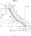
Fig. 2 is a side view in which a main portion of the non-pneumatic tire shown inFig. 1 is enlarged and reference distances between points are shown. -
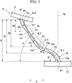
Fig. 3 is a side view in which a main portion of the non-pneumatic tire shown inFig. 1 is enlarged and inclination angles related to each point are shown. - As shown in
Figs. 1 to 3 , anon-pneumatic tire 1 of the present embodiment includes anattachment body 11 attached to an axle (not shown), an outercylindrical body 13 in a cylindrical shape which surrounds theattachment body 11 from the outside in a tire radial direction, acoupling body 14 which couples theattachment body 11 and the outercylindrical body 13, and acylindrical tread member 16 wrapped externally around the outercylindrical body 13. - Also, the
non-pneumatic tire 1 of the present embodiment may be employed in a small-sized vehicle traveling at a low speed such as a handle type electric wheelchair specified in Japanese Industrial Standard JIS T 9208, for example. In addition, the size of thenon-pneumatic tire 1 is not particularly limited, but may be in a range of 3.00- 8 or the like, for example. Also, thenon-pneumatic tire 1 may be employed for passenger cars. The size in this case is not particularly limited, but may be 155/65R 13 or the like, for example. - The above-described
attachment body 11, the outercylindrical body 13, and thetread member 16 are coaxially arranged on a common axis. Hereinafter, this common axis is referred to as an axis O, a direction along the axis O is referred to as a tire width direction, a direction perpendicular to the axis O is referred to as a tire radial direction, and a direction of revolving around the axis O is referred to as a tire circumferential direction. Also, center portions in the tire width direction of theattachment body 11, the outercylindrical body 13, and thetread member 16 coincide with each other. - The
attachment body 11 includes afitting cylinder portion 17 to which a distal end portion of the axle is fitted, anouter ring portion 18 which surrounds thefitting cylinder portion 17 from the outside in the tire radial direction, and a plurality ofribs 19 which couple thefitting cylinder portion 17 to theouter ring portion 18. - The
fitting cylinder portion 17, theouter ring portion 18, and theribs 19 are integrally formed of a metal material such as an aluminum alloy, for example. Thefitting cylinder portion 17 and theouter ring portion 18 are formed in a cylindrical shape and are coaxially arranged on the axis O. The plurality ofribs 19 are disposed at regular intervals in the tire circumferential direction, for example. - A plurality of key groove portions (not shown) recessed toward the inside in the tire radial direction and configured to extend in the tire width direction are formed on an outer circumferential surface of the
outer ring portion 18 at intervals in the tire circumferential direction. On the outer circumferential surface of theouter ring portion 18, the key groove portions are open only on one side (outer side of the vehicle body) in the tire width direction and are closed on the other side (inside the vehicle body) in the tire width direction. - An inner
cylindrical body 12 in a cylindrical shape which is externally fitted to theouter ring portion 18 is provided on theattachment body 11. A ridge portion (not shown) protruding toward the inside in the tire radial direction and extending over the entire length in the tire width direction is formed on an inner circumferential surface of the innercylindrical body 12. A plurality of ridge portions are formed on the inner circumferential surface of the innercylindrical body 12 at intervals in the tire circumferential direction and respectively engaged with the key groove portions. - Thus, the inner
cylindrical body 12 is fixed to theattachment body 11 in a state in which the ridge portions are engaged with the key groove portions. In the shown example, the innercylindrical body 12 is fixed to theattachment body 11 byscrewing plates 28 from one side in the tire width direction at a position corresponding to the key groove portions in theouter ring portion 18. - A plurality of
coupling bodies 14 are arranged in a tire circumferential direction between theattachment body 11 and the outercylindrical body 13, and each of thecoupling bodies 14 includes acoupling member 15 which couples theattachment body 11 and the outercylindrical body 13 in an elastically relatively displaceable manner. A plurality ofcoupling members 15 are disposed at intervals in the tire circumferential direction, opposite ends of each of thecoupling members 15 are respectively coupled to theattachment body 11 and the outercylindrical body 13, and a first end portion (outer end portion 15a) which is an outer end portion in the tire radial direction is positioned on one side in the tire circumferential direction of the second end portion (inner end portion 15b) which is an inner end portion in the tire radial direction. Thecoupling member 15 gradually extends toward the other side in the tire circumferential direction from the outside toward the inside in the tire radial direction. - The
coupling member 15 couples an outer circumferential surface side of theattachment body 11 to an inner circumferential surface side of the outercylindrical body 13 in an elastically relatively displaceable manner. Thecoupling member 15 is an elastically deformable plate whose front and rear surfaces are directed in the tire circumferential direction. A plurality ofcoupling members 15 are disposed in the tire circumferential direction. The plurality ofcoupling members 15 are respectively disposed at positions rotationally symmetrical with respect to the axis O between the innercylindrical body 12 and the outercylindrical body 13. All thecoupling members 15 have the same shape and the same size, and the width of thecoupling members 15 in the tire width direction is smaller than the width of the outercylindrical body 13 in the tire width direction.Adjacent coupling members 15 in the tire circumferential direction are not in contact with each other. - As shown in
Figs. 2 and3 , in each of thecoupling members 15, a first end portion (outer end portion 15a) coupled to the outercylindrical body 13 is positioned on one side in the tire circumferential direction of the second end portion (inner end portion 15b) coupled to the innercylindrical body 12. - A plurality of
curved portions 15d to 15f which are curved in the tire circumferential direction are formed in thecoupling member 15 at intermediate portions between theouter end portion 15a and theinner end portion 15b. The plurality ofcurved portions 15d to 15f are formed along an extending direction in which thecoupling member 15 extends in a tire side view when thenon-pneumatic tire 1 is viewed from the tire width direction. In the shown example, the plurality ofcurved portions 15d to 15f of thecoupling member 15 are adjacent to each other in the above-described extending direction while having curvature directions opposite to each other. - The plurality of
curved portions 15d to 15f include a first curvedportion 15d curved to protrude toward the other side in the tire circumferential direction, a secondcurved portion 15e positioned between the firstcurved portion 15d and theouter end portion 15a and curved to protrude toward one side in the tire circumferential direction, and a thirdcurved portion 15f positioned between the first curvedportion 15d and theinner end portion 15b and curved to protrude toward one side in the tire circumferential direction. In addition,inflection portions coupling member 15 at portions positioned between each of thecurved portions 15d to 15f adjacent to each other in the extending direction of thecoupling member 15. - The above-described inner
cylindrical body 12, the outercylindrical body 13, and the plurality of coupling members 15 (the coupling body 14) are integrally formed of a synthetic resin material, for example. The synthetic resin material may be, for example, a single resin material, a mixture containing two or more kinds of resin material, or a mixture containing one or more kinds of resin material and one or more kinds of elastomer, and furthermore, may include additives such as anti-aging agents, plasticizers, fillers, or pigments, for example. - Hereinafter, a unit in which the inner
cylindrical body 12, the outercylindrical body 13, and thecoupling member 15 are integrally formed is referred to as acase body 31. - The
case body 31 can be integrally formed by injection molding, for example. The injection molding may include a general method of molding theentire case body 31 at once, insert molding in which the remaining portions other than insert parts are injection molded with some portions among the innercylindrical body 12, the outercylindrical body 13, and thecoupling member 15 being provided as the insert parts, a so-called two-color molding, or the like. In addition, when the entirety of thecase body 31 is injection-molded at once, a plurality of protrusions formed on the innercylindrical body 12 may be a gate portion. Further, at the time of injection-molding, the innercylindrical body 12, the outercylindrical body 13, and thecoupling member 15 may be formed of different materials, or may be formed of the same material. As such materials, metal materials, resin materials, or the like are examples; however, resin materials, particularly thermoplastic resins, are preferable from the perspective of reducing weight. - As shown in
Fig. 1 , thetread member 16 is formed in a cylindrical shape and integrally covers an outer circumferential surface side of the outercylindrical body 13 over the entire region. An inner circumferential surface of thetread member 16 is in close contact with the outer circumferential surface of the outercylindrical body 13 over the entire region. Thetread member 16 is formed of a natural rubber and/or a vulcanized rubber in which the rubber composition is vulcanized, a thermoplastic material, or the like, for example. - As the thermoplastic material, a thermoplastic elastomer, a thermoplastic resin, or the like is an example. As thermoplastic elastomers, amide-based thermoplastic elastomers (TPA), ester-based thermoplastic elastomers (TPC), olefin-based thermoplastic elastomers (TPO), styrene-based thermoplastic elastomers (TPS), urethane-based thermoplastic elastomers (TPU), a thermoplastic rubber cross-linked body (TPV), other thermoplastic elastomers (TPZ), or the like, specified in Japanese Industrial Standard JIS K6418, are examples.
- As the thermoplastic resin, urethane resins, olefin resins, vinyl chloride resins, polyamide resins, or the like are examples. Also, it is preferable to form the
tread member 16 with a vulcanized rubber from the perspective of wear resistance. - In the present embodiment, the
non-pneumatic tire 1 satisfies the following relationships. - That is, first, as shown in
Figs. 2 and3 , in a tire side view when thenon-pneumatic tire 1 is viewed from the tire width direction, a first point P1, a second point P2, a third point P3, a fourth point P4, and a fifth point P5 are set in order from theouter end portion 15a side toward theinner end portion 15b side on a center line CL passing through a center in the tire circumferential direction of thecoupling member 15 over the entire length from theouter end portion 15a to theinner end portion 15b of thecoupling member 15. Among these first point P1 to the fifth point P5, the first point P1 is set on an end edge on theouter end portion 15a side of thecoupling member 15 and the fifth point P5 is set on an end edge on theinner end portion 15b side of thecoupling member 15. Further, the end edge on theouter end portion 15a side of thecoupling member 15 is positioned on the inner circumferential surface of the outercylindrical body 13 and the end edge on theinner end portion 15b side of thecoupling member 15 is positioned on an outer circumferential surface of the innercylindrical body 12. Also, the distance between the first point P1 and the fifth point P5 along a reference straight line RL passing through the first point P1 and the axis O (tire axis) is referred to as H. Further, the reference straight line RL extends in a tangential direction with respect to a portion of the inner circumferential surface of the outercylindrical body 13 at which the first point P1 is positioned. Then, a distance H1 from the fifth point P5 to the second point P2 along the reference straight line RL is set to 0.80 times the reference distance H, a distance H2 from the fifth point P5 to the third point P3 along the reference straight line is set to 0.65 times the reference distance H, and a distance H3 from the fifth point P5 to the fourth point P4 along the reference straight line is set to 0.30 times the reference distance H. - At this time, as shown in
Fig. 2 , the third point P3 is disposed on the other side in the tire circumferential direction of an overall inclined straight line SL passing through the first point P1 and the fifth point P5. Also, a horizontal distance D2 between the second point P2 and the third point P3 in a perpendicular direction D perpendicular to the reference straight line RL is larger than a horizontal distance D1 between the first point P1 and the second point P2 in the perpendicular direction D and a horizontal distance D4 between the fourth point P4 and the fifth point P5 in the perpendicular direction D. - In the present embodiment, a horizontal distance D3 between the third point P3 and the fourth point P4 in the perpendicular direction D is larger than each of the horizontal distance D1 and the horizontal distance D4.
- As shown in
Fig. 2 , the second point P2 is disposed on one side in the tire circumferential direction of the overall inclined straight line SL passing through the first point P1 and the fifth point P5. The second inclined straight line SL2 passing through the second point P2 and the third point P3 intersects the overall inclined straight line SL. - That is, when a portion in which the third point P3 is positioned protrudes to the other side in the tire circumferential direction, a portion in which the second point P2 is positioned protrudes to one side in the tire circumferential direction.
- Also, as shown in
Fig. 3 , an inclination angle θ2 of a second inclined straight line SL2 passing through the second point P2 and the third point P3 with respect to the perpendicular direction D is smaller than an inclination angle θ1 of a first inclined straight line SL1 passing through the first point P1 and the second point P2 with respect to the perpendicular direction D and an inclination angle θ4 of a fourth inclined straight line SL4 passing through the fourth point P4 and the fifth point P5 with respect to the perpendicular direction D. - Further, an inclination angle θ3 of a third inclined straight line SL3 passing through the third point P3 and the fourth point P4 with respect to the perpendicular direction D is larger than the inclination angle θ2, and the inclination angle θ4 is larger than the inclination angle θ3.
- Thus, a thickness (plate thickness) which is a size in the tire circumferential direction of the
coupling member 15 gradually decreases (becomes thinner) from each of the first point P1 and the fifth point P5 toward the fourth point P4. - Also, in the present embodiment, an inclination angle θ of the overall inclined straight line SL with respect to the perpendicular direction D and the inclination angle θ3 satisfy a relationship of the following expression (1).

- Further, in the present embodiment, the inclination angles θ1, θ2, θ3, and θ4 satisfy relationships of the following expressions (2) to (5).


- Further, it is preferable that the inclination angles θ, θ1, θ2, θ3, and θ4 satisfy relationships of the following expressions (1)' to (5)'.


- As described above, according to the
non-pneumatic tire 1 of the present embodiment, since the third point P3 is disposed on the other side in the tire circumferential direction of the overall inclined straight line SL, it is possible to cause the portion of thecoupling member 15 at which the third point P3 is positioned to protrude to the other side in the tire circumferential direction. In addition, since the horizontal distance D2 between the second point P2 and the third point P3 is larger than the horizontal distance D1 between the first point P1 and the second point P2 and the horizontal distance D4 between the fourth point P4 and the fifth point P5, a portion of thecoupling member 15 positioned between the second point P2 and the third point P3 can to a great extent be easily made to lie against the reference straight line RL. - As described above, when a compressive force in the tire radial direction is applied to the
coupling member 15 between theattachment body 11 and the outercylindrical body 13, a center portion of thecoupling member 15 from the second point P2 to the fourth point P4 through the third point P3 is gently bent and deformed toward the other side in the tire circumferential direction so that the both end portions of thecoupling member 15 cannot be easily deformed. Thereby, concentration of stress in thecoupling member 15 can be prevented and durability can be enhanced. - In addition, the inclination angle θ2 of the second inclined straight line SL2 is smaller than the inclination angle θ1 of the first inclined straight line SL1 and the inclination angle θ4 of the fourth inclined straight line SL4. Therefore, the portion of the
coupling member 15 positioned between the second point P2 and the third point P3 can be reliably made to lie against the reference straight line RL. - Since the inclination angle θ3 of the third inclined straight line SL3 is larger than the inclination angle θ2 of the second inclined straight line SL2, the center portion of the
coupling member 15 is formed to protrude toward the other side in the tire circumferential direction in a tire side view so that it can be easily bent and deformed. - Since the inclination angle θ4 of the fourth inclined straight line SL4 is larger than the inclination angle θ3 of the third inclined straight line SL3, a portion of the
coupling member 15 positioned between the fourth point P4 and the fifth point P5 can be raised up as compared with the portion positioned between the second point P2 and the third point P3. Thereby, it is possible to effectively prevent deformation of theinner end portion 15b of thecoupling member 15. - In addition, since a size of the
coupling member 15 in the tire circumferential direction gradually decreases from each of the first point P1 and the fifth point P5 toward the fourth point P4, when thecoupling member 15 is deformed, it is possible to easily deform thecoupling member 15 with a portion positioned on the fourth point P4 of thecoupling member 15 as a starting point. Thereby, it is possible to actively and easily bend and deform the center portion of thecoupling member 15. - The technical scope of the present invention is not limited to the above embodiments, and various modifications can be added to the scope of the present invention without departing from the spirit of the present invention.
- For example, although in the above-described embodiment, the inner
cylindrical body 12, the outercylindrical body 13, and thecoupling member 15 are integrally formed by, for example, injection molding, the present invention is not limited to injection molding, and they may be integrally formed by, for example, casting or the like. Also, the innercylindrical body 12, the outercylindrical body 13, and thecoupling member 15 may be individually formed and then coupled to each other. - Further, in the embodiment described above, the
coupling member 15 is indirectly coupled to theouter ring portion 18 of theattachment body 11 via the innercylindrical body 12, but the present invention is not limited thereto, and, for example, thecoupling member 15 may be directly coupled to theouter ring portion 18 of theattachment body 11. In this case, the end edge on theinner end portion 15b side of thecoupling member 15 is positioned on the outer circumferential surface of theouter ring portion 18, and the fifth point P5 can be set on the outer circumferential surface of theouter ring portion 18. - In addition, the components in the above-described embodiments can be appropriately replaced with well-known components without departing from the spirit and scope of the present invention, and furthermore, the above-described modified examples may be appropriately combined.
- Next, a verification test on the operation and effects described above was conducted.
- In this verification test, for each non-pneumatic tire of a comparative example and an example, in a simulation using a finite element method, maximum values of stress generated in tires when a load was applied were compared.
- With the non-pneumatic tire shown in
Fig. 1 being assumed to be a basic shape, in each non-pneumatic tire of the comparative example and the example, values of the inclination angles θ1 to θ4 and θ and the horizontal distances D1 to D4 were set to respective values as shown in Table 1 below. - In Table 1, the unit of each value of the inclination angles θ1 to θ4, and θ is "degrees (°)" and the unit of each value of the horizontal distances D1 to D4 is "millimeters (mm)."
[Table 1] Comparative example Example θ1 38.1 52.7 θ2 58.9 23.5 θ3 56.0 50.7 θ4 39.6 62.1 θ 46.7 46.7 D1 15.5 9.3 D2 5.5 21.0 D3 14.4 17.4 D4 22.0 9.7 - As shown in each value in Table 1, in the non-pneumatic tire of the example, a horizontal distance D2 was larger than each of horizontal distances D1 and D4, an inclination angle θ2 was smaller than each of inclination angles θ1 and θ4, an inclination angle θ3 was larger than the inclination angle θ2, and the inclination angle θ4 was larger than the inclination angle θ3.
- On the other hand, in the non-pneumatic tire of the comparative example, a horizontal distance D2 was smaller than each of horizontal distances D1 and D4, an inclination angle θ2 was larger than each of inclination angles θ1 and θ4, an inclination angle θ3 was smaller than the inclination angle θ2, and the inclination angle θ4 was smaller than an inclination angle θ3.
- As a result of this verification test, it was confirmed that a maximum stress in the non-pneumatic tire of the example was reduced to 55 when a maximum stress in the non-pneumatic tire of the comparative example was set to 100.
- According to the present invention, since the third point is disposed on the other side in the tire circumferential direction of the overall inclined straight line, it is possible to cause a portion of the coupling member in which the third point is positioned to protrude to the other side in the tire circumferential direction. In addition, since the horizontal distance D2 between the second point and the third point is larger than the horizontal distance D1 between the first point and the second point and larger than the horizontal distance D4 between the fourth point and the fifth point, a portion of the coupling member positioned between the second point and the third point can to a great extent be easily made to lie against the reference straight line.
- As described above, when a compressive force in the tire radial direction is applied to the coupling member between the attachment body and the outer cylindrical body, a center portion of the coupling member from the second point to the fourth point through the third point is gently bent and deformed toward the other side in the tire circumferential direction so that the both end portions of the coupling member cannot be easily deformed. Thereby, concentration of stress in the coupling member can be prevented and durability can be enhanced.
- The inclination angle θ2 of the second inclined straight line passing through the second point and the third point with respect to the perpendicular direction may be smaller than the inclination angle θ1 of the first inclined straight line passing through the first point and the second point with respect to the perpendicular direction and smaller than the inclination angle θ4 of the fourth inclined straight line passing through the fourth point and the fifth point with respect to the perpendicular direction.
- In this case, the inclination angle θ2 of the second inclined straight line is smaller than each of the inclination angle θ1 of the first inclined straight line and the inclination angle θ4 of the fourth inclined straight line. Therefore, the portion of the coupling member positioned between the second point and the third point can to a great extent be reliably made to lie against the reference straight line.
- The inclination angle θ3 of the third inclined straight line passing through the third point and the fourth point with respect to the perpendicular direction may be larger than the inclination angle θ2.
- In this case, since the inclination angle θ3 of the third inclined straight line is larger than the inclination angle θ2 of the second inclined straight line, the center portion of the coupling member is formed to protrude toward the other side in the tire circumferential direction in a tire side view so that it can be easily bent and deformed.
- The inclination angle θ4 may be larger than the inclination angle θ3.
- In this case, since the inclination angle θ4 of the fourth inclined straight line is larger than the inclination angle θ3 of the third inclined straight line, the portion of the coupling member positioned between the fourth point and the fifth point can be raised up as compared with the portion positioned between the second point and the third point. Thereby, it is possible to effectively prevent deformation of the second end portion of the coupling member.
- The size of the coupling member in the tire circumferential direction may gradually decrease from each of the first point and the fifth point toward the fourth point.
- In this case, since the size of the coupling member in the tire circumferential direction gradually decreases from each of the first point and the fifth point toward the fourth point, when the coupling member is deformed, it is possible to easily deform the coupling member with a portion positioned on the fourth point of the coupling member as a starting point. Thereby, it is possible to actively and easily bend and deform the center portion of the coupling member.
- According to the present invention, durability of the non-pneumatic tire can be enhanced.
-
- 1 Non-pneumatic tire
- 11 Attachment body
- 13 Outer cylindrical body
- 14 Coupling body
- 15 Coupling member
- 15a Outer end portion (a first end portion)
- 15b Inner end portion (the second end portion)
- CL Center line
- D Perpendicular direction
- D1, D2, D4 Horizontal distance
- H Reference distance
- HI, H2, H3 Distance
- O Axis (tire axis)
- P1 First point
- P2 Second point
- P3 Third point
- P4 Fourth point
- P5 Fifth point
- RL Reference straight line
- SL Overall inclined straight line
- SL1 First inclined straight line
- SL2 Second inclined straight line
- SL3 Third inclined straight line
- SL4 Fourth inclined straight line
- θ, θ1, θ2, θ3, θ4 Inclination angle
Claims (6)
- A non-pneumatic tire comprising:an attachment body attached to an axle;an outer cylindrical body which surrounds the attachment body from the outside in a tire radial direction; anda coupling body which couples the outer cylindrical body and the attachment body, wherein the coupling body includes a plurality of coupling members disposed at intervals in a tire circumferential direction, opposite ends of each of the coupling members are respectively coupled to the attachment body and the outer cylindrical body, and a first end portion which is an outer end portion of the coupling member in the tire radial direction is positioned on one side in the tire circumferential direction of a second end portion which is an inner end portion in the tire radial direction,wherein, in a tire side view when the non-pneumatic tire is viewed from a tire width direction,when a first point, a second point, a third point, a fourth point, and a fifth point are set in order from the first end portion side toward the second end portion side on a center line passing through a center in the tire circumferential direction of the coupling member over the entire length from the first end portion to the second end portion of the coupling member,when the first point is set on an end edge on the first end portion side of the coupling member and the fifth point is set on an end edge on the second end portion side of the coupling member, andwhen a distance H1 from the fifth point to the second point along a reference straight line passing through the first point and a tire axis is set to 0.80 times a reference distance H from the fifth point to the first point along the reference straight line, a distance H2 from the fifth point to the third point along the reference straight line is set to 0.65 times the reference distance H, and a distance H3 from the fifth point to the fourth point along the reference straight line is set to 0.30 times the reference distance H,the third point is disposed on the other side in the tire circumferential direction of an overall inclined straight line passing through the first point and the fifth point, anda horizontal distance D2 between the second point and the third point in a perpendicular direction perpendicular to the reference straight line is larger than each of a horizontal distance D1 between the first point and the second point in the perpendicular direction and a horizontal distance D4 between the fourth point and the fifth point in the perpendicular direction.
- The non-pneumatic tire according to claim 1, wherein an inclination angle θ2 of a second inclined straight line passing through the second point and the third point with respect to the perpendicular direction is smaller than each of an inclination angle θ1 of a first inclined straight line passing through the first point and the second point with respect to the perpendicular direction and an inclination angle θ4 of a fourth inclined straight line passing through the fourth point and the fifth point with respect to the perpendicular direction.
- The non-pneumatic tire according to claim 2, wherein an inclination angle θ3 of a third inclined straight line passing through the third point and the fourth point with respect to the perpendicular direction is larger than the inclination angle θ2.
- The non-pneumatic tire according to claim 3, wherein the inclination angle θ4 is larger than the inclination angle θ3.
- The non-pneumatic tire according to any one of claims 1 to 4, wherein a size of the coupling member in the tire circumferential direction gradually decreases from each of the first point and the fifth point toward the fourth point.
- The non-pneumatic tire according to claim 1, wherein the second point is disposed on one side in the tire circumferential direction of the overall inclined straight line passing through the first point and the fifth point.
Applications Claiming Priority (2)
| Application Number | Priority Date | Filing Date | Title |
|---|---|---|---|
| JP2015201279 | 2015-10-09 | ||
| PCT/JP2016/079405 WO2017061405A1 (en) | 2015-10-09 | 2016-10-04 | Non-pneumatic tire |
Publications (3)
| Publication Number | Publication Date |
|---|---|
| EP3360698A1 true EP3360698A1 (en) | 2018-08-15 |
| EP3360698A4 EP3360698A4 (en) | 2018-09-26 |
| EP3360698B1 EP3360698B1 (en) | 2020-01-01 |
Family
ID=58487608
Family Applications (1)
| Application Number | Title | Priority Date | Filing Date |
|---|---|---|---|
| EP16853559.9A Active EP3360698B1 (en) | 2015-10-09 | 2016-10-04 | Non-pneumatic tire |
Country Status (5)
| Country | Link |
|---|---|
| US (1) | US10836211B2 (en) |
| EP (1) | EP3360698B1 (en) |
| JP (1) | JP6746598B2 (en) |
| CN (1) | CN108136835B (en) |
| WO (1) | WO2017061405A1 (en) |
Families Citing this family (14)
| Publication number | Priority date | Publication date | Assignee | Title |
|---|---|---|---|---|
| EP3007909A4 (en) | 2013-06-15 | 2017-03-01 | Ronald Thompson | Annular ring and non-pneumatic tire |
| CA2976055A1 (en) | 2015-02-04 | 2016-08-11 | Advancing Mobility, Llc. | Non-pneumatic tire and other annular devices |
| USD832770S1 (en) * | 2016-10-28 | 2018-11-06 | Bridgestone Corporation | Non-pneumatic tire |
| JP6842361B2 (en) | 2017-05-11 | 2021-03-17 | 株式会社ブリヂストン | Non-pneumatic tires |
| WO2018227276A1 (en) | 2017-06-15 | 2018-12-20 | Camso Inc. | Wheel comprising a non-pneumatic tire |
| JP6964470B2 (en) * | 2017-09-07 | 2021-11-10 | Toyo Tire株式会社 | Non-pneumatic tire |
| JP7004562B2 (en) * | 2017-12-14 | 2022-02-10 | Toyo Tire株式会社 | Non-pneumatic tires |
| JP7123770B2 (en) * | 2018-11-30 | 2022-08-23 | 株式会社ブリヂストン | non-pneumatic tire |
| JP7123771B2 (en) * | 2018-11-30 | 2022-08-23 | 株式会社ブリヂストン | non-pneumatic tire |
| CN110039957B (en) * | 2019-04-24 | 2023-11-03 | 北京化工大学 | Safe, green, energy-saving and noise-reducing non-pneumatic tire |
| JP1654471S (en) * | 2019-05-23 | 2020-03-09 | ||
| JP1654441S (en) * | 2019-05-23 | 2020-03-09 | ||
| JP1654332S (en) * | 2019-07-12 | 2020-03-09 | ||
| JP2022126478A (en) * | 2021-02-18 | 2022-08-30 | 住友ゴム工業株式会社 | airless tire |
Family Cites Families (19)
| Publication number | Priority date | Publication date | Assignee | Title |
|---|---|---|---|---|
| US1187042A (en) * | 1915-03-18 | 1916-06-13 | Spencer A Cherry | Spring-wheel. |
| US1442897A (en) * | 1917-08-27 | 1923-01-23 | William P J Murray | Spring wheel |
| GB191601A (en) * | 1921-12-29 | 1923-01-18 | William Jakob Beisel | Improvements in or relating to vehicle wheels |
| JPH03189202A (en) * | 1989-12-20 | 1991-08-19 | Yokohama Rubber Co Ltd:The | Non-pneumatic tire |
| EP1378377A2 (en) * | 2002-07-01 | 2004-01-07 | Technology Investments Limited | A lightweight resilient wheel |
| US20090294000A1 (en) * | 2006-09-20 | 2009-12-03 | Cron Steven M | Variable Stiffness Spoke For a Non-Pneumatic Assembly |
| WO2012030519A2 (en) * | 2010-09-01 | 2012-03-08 | Michelin Recherche Et Technique S.A. | Spoke edge geometry for a non-pneumatic tire |
| JP5879089B2 (en) | 2011-10-20 | 2016-03-08 | 株式会社ブリヂストン | Non-pneumatic tire manufacturing method |
| KR101362120B1 (en) | 2011-11-22 | 2014-02-13 | 한국타이어 주식회사 | Airless tire |
| IN2014DN06729A (en) * | 2012-04-05 | 2015-05-22 | Michelin & Cie | |
| KR101378436B1 (en) * | 2012-06-27 | 2014-03-27 | 한국타이어 주식회사 | Airless tire |
| US20140062168A1 (en) * | 2012-08-30 | 2014-03-06 | Caterpillar Inc. | Non-pneumatic tire |
| JP6043582B2 (en) | 2012-10-22 | 2016-12-14 | 株式会社ブリヂストン | Non pneumatic tire |
| JP5930941B2 (en) | 2012-10-31 | 2016-06-08 | 株式会社ブリヂストン | Non pneumatic tire |
| JP6061625B2 (en) | 2012-11-05 | 2017-01-18 | 株式会社ブリヂストン | Non pneumatic tire |
| JP2014125079A (en) * | 2012-12-26 | 2014-07-07 | Bridgestone Corp | Non-pneumatic tire |
| JP6288928B2 (en) * | 2013-03-26 | 2018-03-07 | 株式会社ブリヂストン | Non pneumatic tire |
| JP6152036B2 (en) | 2013-10-21 | 2017-06-21 | 株式会社ブリヂストン | Non pneumatic tire |
| JP6221113B2 (en) * | 2013-11-15 | 2017-11-01 | 株式会社ブリヂストン | Non pneumatic tire |
-
2016
- 2016-10-04 WO PCT/JP2016/079405 patent/WO2017061405A1/en active Application Filing
- 2016-10-04 EP EP16853559.9A patent/EP3360698B1/en active Active
- 2016-10-04 CN CN201680058303.6A patent/CN108136835B/en active Active
- 2016-10-04 JP JP2017544496A patent/JP6746598B2/en active Active
- 2016-10-04 US US15/764,068 patent/US10836211B2/en active Active
Also Published As
| Publication number | Publication date |
|---|---|
| JPWO2017061405A1 (en) | 2018-08-30 |
| JP6746598B2 (en) | 2020-08-26 |
| WO2017061405A1 (en) | 2017-04-13 |
| CN108136835A (en) | 2018-06-08 |
| US10836211B2 (en) | 2020-11-17 |
| EP3360698A4 (en) | 2018-09-26 |
| CN108136835B (en) | 2019-11-22 |
| EP3360698B1 (en) | 2020-01-01 |
| US20180222254A1 (en) | 2018-08-09 |
Similar Documents
| Publication | Publication Date | Title |
|---|---|---|
| EP3360698B1 (en) | Non-pneumatic tire | |
| US10399381B2 (en) | Non-pneumatic tire | |
| EP3235660A1 (en) | Non-pneumatic tire | |
| US20170305195A1 (en) | Non-pneumatic tire | |
| WO2014103723A1 (en) | Non-pneumatic tyre | |
| EP3246178B1 (en) | Non-pneumatic tire | |
| EP3121029B1 (en) | Non-pneumatic tire | |
| EP3272549B1 (en) | Non-pneumatic tire | |
| JP6293060B2 (en) | Non pneumatic tire | |
| WO2014069570A1 (en) | Non-pneumatic tire | |
| WO2014065263A1 (en) | Non-pneumatic tire | |
| US10576786B2 (en) | Non-pneumatic tire | |
| WO2015052989A1 (en) | Non-pneumatic tire | |
| JP6106428B2 (en) | Non pneumatic tire | |
| US11312178B2 (en) | Non-pneumatic tire | |
| US20210138830A1 (en) | Non-pneumatic tire | |
| JP2016107751A (en) | Non-pneumatic tire | |
| US11766894B2 (en) | Non-pneumatic tire | |
| EP3888937A1 (en) | Non-pneumatic tire | |
| JP6522936B2 (en) | Non pneumatic tire | |
| JP6522931B2 (en) | Non pneumatic tire |
Legal Events
| Date | Code | Title | Description |
|---|---|---|---|
| STAA | Information on the status of an ep patent application or granted ep patent |
Free format text: STATUS: THE INTERNATIONAL PUBLICATION HAS BEEN MADE |
|
| PUAI | Public reference made under article 153(3) epc to a published international application that has entered the european phase |
Free format text: ORIGINAL CODE: 0009012 |
|
| STAA | Information on the status of an ep patent application or granted ep patent |
Free format text: STATUS: REQUEST FOR EXAMINATION WAS MADE |
|
| 17P | Request for examination filed |
Effective date: 20180329 |
|
| AK | Designated contracting states |
Kind code of ref document: A1 Designated state(s): AL AT BE BG CH CY CZ DE DK EE ES FI FR GB GR HR HU IE IS IT LI LT LU LV MC MK MT NL NO PL PT RO RS SE SI SK SM TR |
|
| AX | Request for extension of the european patent |
Extension state: BA ME |
|
| A4 | Supplementary search report drawn up and despatched |
Effective date: 20180828 |
|
| RIC1 | Information provided on ipc code assigned before grant |
Ipc: B60B 9/04 20060101ALI20180822BHEP Ipc: B60C 7/00 20060101AFI20180822BHEP |
|
| DAV | Request for validation of the european patent (deleted) | ||
| DAX | Request for extension of the european patent (deleted) | ||
| GRAP | Despatch of communication of intention to grant a patent |
Free format text: ORIGINAL CODE: EPIDOSNIGR1 |
|
| STAA | Information on the status of an ep patent application or granted ep patent |
Free format text: STATUS: GRANT OF PATENT IS INTENDED |
|
| INTG | Intention to grant announced |
Effective date: 20190614 |
|
| GRAS | Grant fee paid |
Free format text: ORIGINAL CODE: EPIDOSNIGR3 |
|
| GRAA | (expected) grant |
Free format text: ORIGINAL CODE: 0009210 |
|
| STAA | Information on the status of an ep patent application or granted ep patent |
Free format text: STATUS: THE PATENT HAS BEEN GRANTED |
|
| AK | Designated contracting states |
Kind code of ref document: B1 Designated state(s): AL AT BE BG CH CY CZ DE DK EE ES FI FR GB GR HR HU IE IS IT LI LT LU LV MC MK MT NL NO PL PT RO RS SE SI SK SM TR |
|
| REG | Reference to a national code |
Ref country code: GB Ref legal event code: FG4D |
|
| REG | Reference to a national code |
Ref country code: CH Ref legal event code: EP Ref country code: AT Ref legal event code: REF Ref document number: 1219316 Country of ref document: AT Kind code of ref document: T Effective date: 20200115 |
|
| REG | Reference to a national code |
Ref country code: IE Ref legal event code: FG4D |
|
| REG | Reference to a national code |
Ref country code: DE Ref legal event code: R096 Ref document number: 602016027581 Country of ref document: DE |
|
| REG | Reference to a national code |
Ref country code: NL Ref legal event code: MP Effective date: 20200101 |
|
| REG | Reference to a national code |
Ref country code: LT Ref legal event code: MG4D |
|
| PG25 | Lapsed in a contracting state [announced via postgrant information from national office to epo] |
Ref country code: CZ Free format text: LAPSE BECAUSE OF FAILURE TO SUBMIT A TRANSLATION OF THE DESCRIPTION OR TO PAY THE FEE WITHIN THE PRESCRIBED TIME-LIMIT Effective date: 20200101 Ref country code: NL Free format text: LAPSE BECAUSE OF FAILURE TO SUBMIT A TRANSLATION OF THE DESCRIPTION OR TO PAY THE FEE WITHIN THE PRESCRIBED TIME-LIMIT Effective date: 20200101 Ref country code: NO Free format text: LAPSE BECAUSE OF FAILURE TO SUBMIT A TRANSLATION OF THE DESCRIPTION OR TO PAY THE FEE WITHIN THE PRESCRIBED TIME-LIMIT Effective date: 20200401 Ref country code: FI Free format text: LAPSE BECAUSE OF FAILURE TO SUBMIT A TRANSLATION OF THE DESCRIPTION OR TO PAY THE FEE WITHIN THE PRESCRIBED TIME-LIMIT Effective date: 20200101 Ref country code: PT Free format text: LAPSE BECAUSE OF FAILURE TO SUBMIT A TRANSLATION OF THE DESCRIPTION OR TO PAY THE FEE WITHIN THE PRESCRIBED TIME-LIMIT Effective date: 20200527 Ref country code: RS Free format text: LAPSE BECAUSE OF FAILURE TO SUBMIT A TRANSLATION OF THE DESCRIPTION OR TO PAY THE FEE WITHIN THE PRESCRIBED TIME-LIMIT Effective date: 20200101 Ref country code: LT Free format text: LAPSE BECAUSE OF FAILURE TO SUBMIT A TRANSLATION OF THE DESCRIPTION OR TO PAY THE FEE WITHIN THE PRESCRIBED TIME-LIMIT Effective date: 20200101 |
|
| PG25 | Lapsed in a contracting state [announced via postgrant information from national office to epo] |
Ref country code: BG Free format text: LAPSE BECAUSE OF FAILURE TO SUBMIT A TRANSLATION OF THE DESCRIPTION OR TO PAY THE FEE WITHIN THE PRESCRIBED TIME-LIMIT Effective date: 20200401 Ref country code: LV Free format text: LAPSE BECAUSE OF FAILURE TO SUBMIT A TRANSLATION OF THE DESCRIPTION OR TO PAY THE FEE WITHIN THE PRESCRIBED TIME-LIMIT Effective date: 20200101 Ref country code: SE Free format text: LAPSE BECAUSE OF FAILURE TO SUBMIT A TRANSLATION OF THE DESCRIPTION OR TO PAY THE FEE WITHIN THE PRESCRIBED TIME-LIMIT Effective date: 20200101 Ref country code: IS Free format text: LAPSE BECAUSE OF FAILURE TO SUBMIT A TRANSLATION OF THE DESCRIPTION OR TO PAY THE FEE WITHIN THE PRESCRIBED TIME-LIMIT Effective date: 20200501 Ref country code: HR Free format text: LAPSE BECAUSE OF FAILURE TO SUBMIT A TRANSLATION OF THE DESCRIPTION OR TO PAY THE FEE WITHIN THE PRESCRIBED TIME-LIMIT Effective date: 20200101 Ref country code: GR Free format text: LAPSE BECAUSE OF FAILURE TO SUBMIT A TRANSLATION OF THE DESCRIPTION OR TO PAY THE FEE WITHIN THE PRESCRIBED TIME-LIMIT Effective date: 20200402 |
|
| REG | Reference to a national code |
Ref country code: DE Ref legal event code: R097 Ref document number: 602016027581 Country of ref document: DE |
|
| PG25 | Lapsed in a contracting state [announced via postgrant information from national office to epo] |
Ref country code: SM Free format text: LAPSE BECAUSE OF FAILURE TO SUBMIT A TRANSLATION OF THE DESCRIPTION OR TO PAY THE FEE WITHIN THE PRESCRIBED TIME-LIMIT Effective date: 20200101 Ref country code: EE Free format text: LAPSE BECAUSE OF FAILURE TO SUBMIT A TRANSLATION OF THE DESCRIPTION OR TO PAY THE FEE WITHIN THE PRESCRIBED TIME-LIMIT Effective date: 20200101 Ref country code: SK Free format text: LAPSE BECAUSE OF FAILURE TO SUBMIT A TRANSLATION OF THE DESCRIPTION OR TO PAY THE FEE WITHIN THE PRESCRIBED TIME-LIMIT Effective date: 20200101 Ref country code: DK Free format text: LAPSE BECAUSE OF FAILURE TO SUBMIT A TRANSLATION OF THE DESCRIPTION OR TO PAY THE FEE WITHIN THE PRESCRIBED TIME-LIMIT Effective date: 20200101 Ref country code: RO Free format text: LAPSE BECAUSE OF FAILURE TO SUBMIT A TRANSLATION OF THE DESCRIPTION OR TO PAY THE FEE WITHIN THE PRESCRIBED TIME-LIMIT Effective date: 20200101 Ref country code: ES Free format text: LAPSE BECAUSE OF FAILURE TO SUBMIT A TRANSLATION OF THE DESCRIPTION OR TO PAY THE FEE WITHIN THE PRESCRIBED TIME-LIMIT Effective date: 20200101 |
|
| PLBE | No opposition filed within time limit |
Free format text: ORIGINAL CODE: 0009261 |
|
| STAA | Information on the status of an ep patent application or granted ep patent |
Free format text: STATUS: NO OPPOSITION FILED WITHIN TIME LIMIT |
|
| REG | Reference to a national code |
Ref country code: AT Ref legal event code: MK05 Ref document number: 1219316 Country of ref document: AT Kind code of ref document: T Effective date: 20200101 |
|
| 26N | No opposition filed |
Effective date: 20201002 |
|
| PG25 | Lapsed in a contracting state [announced via postgrant information from national office to epo] |
Ref country code: AT Free format text: LAPSE BECAUSE OF FAILURE TO SUBMIT A TRANSLATION OF THE DESCRIPTION OR TO PAY THE FEE WITHIN THE PRESCRIBED TIME-LIMIT Effective date: 20200101 Ref country code: IT Free format text: LAPSE BECAUSE OF FAILURE TO SUBMIT A TRANSLATION OF THE DESCRIPTION OR TO PAY THE FEE WITHIN THE PRESCRIBED TIME-LIMIT Effective date: 20200101 |
|
| PG25 | Lapsed in a contracting state [announced via postgrant information from national office to epo] |
Ref country code: SI Free format text: LAPSE BECAUSE OF FAILURE TO SUBMIT A TRANSLATION OF THE DESCRIPTION OR TO PAY THE FEE WITHIN THE PRESCRIBED TIME-LIMIT Effective date: 20200101 Ref country code: PL Free format text: LAPSE BECAUSE OF FAILURE TO SUBMIT A TRANSLATION OF THE DESCRIPTION OR TO PAY THE FEE WITHIN THE PRESCRIBED TIME-LIMIT Effective date: 20200101 |
|
| REG | Reference to a national code |
Ref country code: CH Ref legal event code: PL |
|
| GBPC | Gb: european patent ceased through non-payment of renewal fee |
Effective date: 20201004 |
|
| PG25 | Lapsed in a contracting state [announced via postgrant information from national office to epo] |
Ref country code: MC Free format text: LAPSE BECAUSE OF FAILURE TO SUBMIT A TRANSLATION OF THE DESCRIPTION OR TO PAY THE FEE WITHIN THE PRESCRIBED TIME-LIMIT Effective date: 20200101 Ref country code: LU Free format text: LAPSE BECAUSE OF NON-PAYMENT OF DUE FEES Effective date: 20201004 |
|
| REG | Reference to a national code |
Ref country code: BE Ref legal event code: MM Effective date: 20201031 |
|
| PG25 | Lapsed in a contracting state [announced via postgrant information from national office to epo] |
Ref country code: GB Free format text: LAPSE BECAUSE OF NON-PAYMENT OF DUE FEES Effective date: 20201004 Ref country code: LI Free format text: LAPSE BECAUSE OF NON-PAYMENT OF DUE FEES Effective date: 20201031 Ref country code: BE Free format text: LAPSE BECAUSE OF NON-PAYMENT OF DUE FEES Effective date: 20201031 Ref country code: CH Free format text: LAPSE BECAUSE OF NON-PAYMENT OF DUE FEES Effective date: 20201031 |
|
| PG25 | Lapsed in a contracting state [announced via postgrant information from national office to epo] |
Ref country code: IE Free format text: LAPSE BECAUSE OF NON-PAYMENT OF DUE FEES Effective date: 20201004 |
|
| PG25 | Lapsed in a contracting state [announced via postgrant information from national office to epo] |
Ref country code: TR Free format text: LAPSE BECAUSE OF FAILURE TO SUBMIT A TRANSLATION OF THE DESCRIPTION OR TO PAY THE FEE WITHIN THE PRESCRIBED TIME-LIMIT Effective date: 20200101 Ref country code: MT Free format text: LAPSE BECAUSE OF FAILURE TO SUBMIT A TRANSLATION OF THE DESCRIPTION OR TO PAY THE FEE WITHIN THE PRESCRIBED TIME-LIMIT Effective date: 20200101 Ref country code: CY Free format text: LAPSE BECAUSE OF FAILURE TO SUBMIT A TRANSLATION OF THE DESCRIPTION OR TO PAY THE FEE WITHIN THE PRESCRIBED TIME-LIMIT Effective date: 20200101 |
|
| PG25 | Lapsed in a contracting state [announced via postgrant information from national office to epo] |
Ref country code: MK Free format text: LAPSE BECAUSE OF FAILURE TO SUBMIT A TRANSLATION OF THE DESCRIPTION OR TO PAY THE FEE WITHIN THE PRESCRIBED TIME-LIMIT Effective date: 20200101 Ref country code: AL Free format text: LAPSE BECAUSE OF FAILURE TO SUBMIT A TRANSLATION OF THE DESCRIPTION OR TO PAY THE FEE WITHIN THE PRESCRIBED TIME-LIMIT Effective date: 20200101 |
|
| P01 | Opt-out of the competence of the unified patent court (upc) registered |
Effective date: 20230531 |
|
| PGFP | Annual fee paid to national office [announced via postgrant information from national office to epo] |
Ref country code: FR Payment date: 20231026 Year of fee payment: 8 Ref country code: DE Payment date: 20231020 Year of fee payment: 8 |