EP3360685B1 - Printer and printer control method - Google Patents
Printer and printer control method Download PDFInfo
- Publication number
- EP3360685B1 EP3360685B1 EP18154953.6A EP18154953A EP3360685B1 EP 3360685 B1 EP3360685 B1 EP 3360685B1 EP 18154953 A EP18154953 A EP 18154953A EP 3360685 B1 EP3360685 B1 EP 3360685B1
- Authority
- EP
- European Patent Office
- Prior art keywords
- sheet
- print data
- label
- thermal head
- transport
- Prior art date
- Legal status (The legal status is an assumption and is not a legal conclusion. Google has not performed a legal analysis and makes no representation as to the accuracy of the status listed.)
- Active
Links
- 238000000034 method Methods 0.000 title claims description 25
- 238000007639 printing Methods 0.000 claims description 129
- 230000032258 transport Effects 0.000 claims description 96
- 230000007246 mechanism Effects 0.000 claims description 28
- 238000012546 transfer Methods 0.000 claims description 6
- 230000008569 process Effects 0.000 description 12
- 238000004891 communication Methods 0.000 description 7
- 238000010438 heat treatment Methods 0.000 description 4
- 238000012545 processing Methods 0.000 description 4
- 238000004804 winding Methods 0.000 description 4
- 230000006870 function Effects 0.000 description 3
- 238000000926 separation method Methods 0.000 description 3
- 238000010586 diagram Methods 0.000 description 2
- 238000011144 upstream manufacturing Methods 0.000 description 2
- 239000000853 adhesive Substances 0.000 description 1
- 230000001070 adhesive effect Effects 0.000 description 1
- 239000012790 adhesive layer Substances 0.000 description 1
- 238000005452 bending Methods 0.000 description 1
- 238000007599 discharging Methods 0.000 description 1
- 238000005516 engineering process Methods 0.000 description 1
- 230000020169 heat generation Effects 0.000 description 1
- 239000004973 liquid crystal related substance Substances 0.000 description 1
- 238000012986 modification Methods 0.000 description 1
- 230000004048 modification Effects 0.000 description 1
- 238000005096 rolling process Methods 0.000 description 1
- 238000006467 substitution reaction Methods 0.000 description 1
Images


Classifications
-
- B—PERFORMING OPERATIONS; TRANSPORTING
- B41—PRINTING; LINING MACHINES; TYPEWRITERS; STAMPS
- B41J—TYPEWRITERS; SELECTIVE PRINTING MECHANISMS, i.e. MECHANISMS PRINTING OTHERWISE THAN FROM A FORME; CORRECTION OF TYPOGRAPHICAL ERRORS
- B41J2/00—Typewriters or selective printing mechanisms characterised by the printing or marking process for which they are designed
- B41J2/315—Typewriters or selective printing mechanisms characterised by the printing or marking process for which they are designed characterised by selective application of heat to a heat sensitive printing or impression-transfer material
- B41J2/32—Typewriters or selective printing mechanisms characterised by the printing or marking process for which they are designed characterised by selective application of heat to a heat sensitive printing or impression-transfer material using thermal heads
- B41J2/325—Typewriters or selective printing mechanisms characterised by the printing or marking process for which they are designed characterised by selective application of heat to a heat sensitive printing or impression-transfer material using thermal heads by selective transfer of ink from ink carrier, e.g. from ink ribbon or sheet
-
- B—PERFORMING OPERATIONS; TRANSPORTING
- B41—PRINTING; LINING MACHINES; TYPEWRITERS; STAMPS
- B41J—TYPEWRITERS; SELECTIVE PRINTING MECHANISMS, i.e. MECHANISMS PRINTING OTHERWISE THAN FROM A FORME; CORRECTION OF TYPOGRAPHICAL ERRORS
- B41J17/00—Mechanisms for manipulating page-width impression-transfer material, e.g. carbon paper
- B41J17/02—Feeding mechanisms
- B41J17/12—Special adaptations for ensuring maximum life
-
- B—PERFORMING OPERATIONS; TRANSPORTING
- B41—PRINTING; LINING MACHINES; TYPEWRITERS; STAMPS
- B41J—TYPEWRITERS; SELECTIVE PRINTING MECHANISMS, i.e. MECHANISMS PRINTING OTHERWISE THAN FROM A FORME; CORRECTION OF TYPOGRAPHICAL ERRORS
- B41J3/00—Typewriters or selective printing or marking mechanisms characterised by the purpose for which they are constructed
- B41J3/407—Typewriters or selective printing or marking mechanisms characterised by the purpose for which they are constructed for marking on special material
- B41J3/4075—Tape printers; Label printers
-
- B—PERFORMING OPERATIONS; TRANSPORTING
- B41—PRINTING; LINING MACHINES; TYPEWRITERS; STAMPS
- B41J—TYPEWRITERS; SELECTIVE PRINTING MECHANISMS, i.e. MECHANISMS PRINTING OTHERWISE THAN FROM A FORME; CORRECTION OF TYPOGRAPHICAL ERRORS
- B41J33/00—Apparatus or arrangements for feeding ink ribbons or like character-size impression-transfer material
- B41J33/14—Ribbon-feed devices or mechanisms
- B41J33/38—Slow, e.g. "creep", feed mechanisms
- B41J33/388—Slow, e.g. "creep", feed mechanisms the ribbon being fed only when type impression takes place
Definitions
- the present invention relates to the field of battery checking technologies in general, and embodiments described herein relate in particular to a printer that prints characters, two-dimensional barcodes, and the like.
- a ribbon transfer type printer is equipped with a function (ribbon saving) of reducing consumption of an ink ribbon by stopping transport of an ink ribbon to a non-printing area.
- a function ribbon saving
- the condition for performing ribbon saving depends on the dimension of the non-printing area
- EP 3075550 A2 discloses a thermal printer with such a ribbon saving function.
- a printer comprising:
- the non-printing area is an area between a last printing area of the first print data and a first printing area of the second print data.
- the control unit separates the thermal head and the platen roller from each other by the clamping mechanism, and stops transport of the ink ribbon by the ribbon transport unit.
- the predetermined threshold is determined, based on the transport speed of the sheet by the transport unit.
- the acquisition unit acquires a plurality of print data
- the non-printing area specifying unit specifies all the non-printing areas from the plurality of print data
- the control unit starts printing by the thermal head, after specifying the non-printing area having a dimension not less than the threshold along the transport direction of the sheet, among all the non-printing areas.
- the invention also relates to a printer control method for controlling a printer including a thermal head configured to thermally transfer ink of an ink ribbon to a label, a platen roller provided opposite to the thermal head, and a clamping mechanism configured to clamp the ink ribbon, a printing area of the label, and the sheet between the thermal head and the platen roller, the method comprising steps of:
- the printer control method further comprises step of: controlling the clamping mechanism to separate the thermal head and the platen roller from each other and stop transport of the ink ribbon by the ribbon transport unit, when the non-printing area has a dimension not less than a predetermined threshold along a transport direction of the sheet.
- the printer control method further comprises step of: determining the predetermined threshold based on the transport speed of the sheet by the transport unit.
- the printer control method further comprises steps of:
- the printer control method further comprises step of: determining whether to perform the clamping mechanism to separate the ink ribbon from the sheet and stop transport of the ink ribbon by the ribbon transport unit, when the transport unit transports the non-printing area on the sheet between the thermal head and the platen roller on the first print data and the second print data.
- An object of an exemplary embodiment is to provide a printer capable of performing ribbon saving more efficiently by optimally performing ribbon saving.
- a printer includes a thermal head, a platen roller, a ribbon transport unit, a transport unit, a clamping mechanism, an acquisition unit, a non-printing area specifying unit, and a control unit.
- the thermal head thermally transfers ink of an ink ribbon to a label.
- the platen roller is provided opposite to the thermal head.
- the ribbon transport unit transports the ink ribbon between the thermal head and the platen roller.
- the transport unit transports a sheet carrying the label between the thermal head and the platen roller such that a printed surface of the label and the thermal head face each other across the ink ribbon.
- the clamping mechanism clamps or separates the thermal head and the platen roller.
- the acquisition unit acquires first print data to be printed on a first label and second print data to be printed on a second label, the second label being adjacent to the first label on the sheet.
- the non-printing area specifying unit specifies a non-printing area on the sheet, based on the first print data and the second print data.
- the control unit separates the ink ribbon from the sheet and stops transport of the ink ribbon by the ribbon transport unit, when the transport unit transports the non-printing area on the sheet between the thermal head and the platen roller.
- FIG. 1 is a perspective view illustrating an overall configuration of a label printer 1 according to the embodiment.
- the label printer 1 includes a control box 10 storing a printer engine, and a cover 20 rotatably connected to the control box 10 by a hinge 15.
- a discharge port 25 for discharging a printed label 54 is provided on the front side of the cover 20, and an operation unit 30 and a display unit 35 that displays operation information and an operation menu are provided on the front side of the control box 10.
- the display unit 35 is configured with a liquid crystal screen or the like.
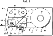
- FIG. 2 is a sectional view of the label printer 1 according to the embodiment.
- the label printer 1 of the embodiment is configured as a line type label printer 1.
- a label printer 1 has a transport path 45 for guiding the label 54 which is a recording medium held in the sheet holding unit 40 in a casing, and has a printing unit 50 in the middle of the transport path 45.
- the label 54 has an adhesive layer on an adhesive surface to a mount, and the label 54 and the mount can be separated as necessary.
- the label 54 and the mount are combined to form a sheet D.
- the sheet roller 55 is formed by rolling the sheet D in a roller shape and is rotatably held by a sheet holding unit 40.
- the transport path 45 is a path for transporting the sheet D from the sheet holding unit 40 to the discharge port 25.
- the printing unit 50 there are the printing unit 50, a label sensor 60 that detects the presence or absence of the label 54 on the upstream side of the printing unit 50, and a transport unit 65.
- the transport unit 65 includes a transport roller 65a and a pinch roller 65b.
- the transport roller 65a and the pinch roller 65b are provided so as to face each other across the transport path 45.
- the transport unit 65 rotatably drives these rollers to transport the sheet D along the transport path 45, and discharges the sheet D from the discharge port 25.
- the printing unit 50 includes a platen roller 50a and a thermal head 50b.
- the platen roller 50a and the thermal head 50b are disposed so as to face each other through the transport path 45.
- the sheet D and an ink ribbon 74 to be described later are transported between the platen roller 50a and the thermal head 50b.
- the thermal head 50b is provided with a head moving mechanism 70 and a heating element (not shown).
- a plurality of heating elements are disposed at predetermined intervals in the direction (main scanning direction) perpendicular to the transport direction A of the sheet D, in the axial direction of the platen roller 50a.
- the printing unit 50 performs printing by each heating element applying heat to the sheet D and the ink ribbon 74.
- the head moving mechanism 70 is a mechanism for varying the distance between the thermal head and the platen roller.
- the head moving mechanism 70 uses a solenoid and a spring to move the thermal head 50b up and down.
- the head moving mechanism 70 may have a head moving function for separating the thermal head 50b from the platen roller 50a by using, for example, an electric actuator.
- the label sensor 60 is disposed between the transport unit 65 and the printing unit 50 along the transport path 45, and detects the presence or absence of the label 54 in the sheet D.
- a transmissive sensor configured with a light emitting unit and a light receiving unit opposed to each other is used.
- the transmissive sensor determines the presence or absence of the label 54 by measuring the intensity of the light received by the light receiving unit with respect to the transmitted light emitted from the light emitting unit, and detects the peak of the intensity at the center of a portion having only the mount between two consecutive labels 54 (hereinafter referred to as a gap g).
- the ink ribbon roller 75 is formed by winding the ink ribbon 74 in a roller shape and is rotatably held by a ribbon holding unit 80.
- the ink ribbon 74 merges with the transport path 45 on the upstream side of the printing unit 50, is directed upward after passing through the printing unit 50, and is wound up on a ribbon winding unit 85.
- the ink ribbon 74 is transported at the same speed as and overlapping with the sheet D, and receives heat from the thermal head 50b and is thermally transferred to the sheet D.
- the discharge port 25 discharges the transported label 54.
- a separation guide may be disposed in the vicinity of the discharge port 25 inside the apparatus.
- the separation guide separates the label 54 from the mount by bending the sheet D at a sharp angle immediately before the discharge port 25, and discharges the separated label 54 from the discharge port 25.
- the mount may be wound up on a mount winding mechanism.
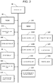
- FIG. 3 is a control block diagram of a label printer 1 of the present embodiment.
- the label printer 1 includes a control unit 90, a ROM 95, a RAM 100, a display control unit 105, a communication unit 110, an operation unit 30, an image generation unit 115, a non-printing area calculation unit 120, a ribbon saving execution unit 125, a motor control unit 130A, a motor control unit 130B, a head control unit 135, a transport motor 140, a ribbon motor 145, and a thermal head 50b. These are communicably connected to each other through a bus line.
- the control unit 90 includes a CPU that controls the overall operation. Operation information, setting information, operation programs, and the like are stored in the ROM 95, and various types of processing information are stored in the RAM 100.
- the display control unit 105 controls the display unit 35, and the communication unit 110 communicates with an external host computer or the like.
- the operation unit 30 includes, for example, various input keys for an operator to manually input data.
- the image generation unit 115 which is an example of an image acquisition unit draws print data to be printed on the label 54 such as characters and two-dimensional barcodes in a buffer.
- the communication unit 110 acquires, for example, information on the print data as a print command from a host computer or the like.
- the non-printing area calculation unit 120 and the ribbon saving execution unit 125 to be described later which are an example of the configuration of the non-printing area specifying unit, specify a non-printing area to be subjected to ribbon saving to be described later.
- the non-printing area calculation unit 120 calculates the dimension of the non-printing area from the print data drawn in the buffer by the image generation unit 115 and the dimension of the gap g previously input by the user.
- the dimension of the gap g may be calculated by the label sensor 60, for example.
- the motor control unit 130A controls the transport motor 140 rotatably driving the transport roller 65a, the pinch roller 65b, and the platen roller 50a constituting the transport unit 65. Further, the motor control unit 130B controls the ribbon motor 145 that rotatably drives the ribbon winding unit 85. In a state where the thermal head 50b is actuated to a head-up state, the motor control unit 130B stops driving of the ribbon motor 145.
- the head control unit 135 controls the head moving mechanism 70 to raise and lower the thermal head 50b and controls printing and non-printing on the label 54. Further, the head control unit 135 controls the heat generation state of the heating elements of the thermal head 50b.
- the ribbon saving is intended to reduce the consumption of a ribbon, by stopping the transport of the ink ribbon 74 to an area where printing is unnecessary. In other words, in ribbon saving, only sheet D is transported to the area where printing is unnecessary.
- the head control unit 135 controls the head moving mechanism 70 so as to actuate the thermal head 50b to a head-up state. Further, the motor control unit 130B stops driving of the ribbon motor 145. The transport unit 65 continues to transport the sheet D during this time. Next, when the sheet D is transported and the thermal head 50b reaches the printing area again, the head control unit 135 controls the head moving mechanism 70 so as to actuate the thermal head 50b to a head-down state. In addition, the motor control unit 130B resumes driving of the ribbon motor 145 according to the head-down state of the thermal head 50b, and performs printing.
- the ribbon saving execution unit 125 determines whether or not to perform the above-described ribbon saving, based on the dimension of the non-printing area calculated by the non-printing area calculation unit 120. If it is determined that the dimension of the non-printing area is not less than a predetermined threshold S (mm), the ribbon saving execution unit 125 performs ribbon saving. On the other hand, if the dimension of the non-printing area is less than S, since the head-up and head-down of the thermal head 50b are not in time with respect to the transport of the sheet D through the non-printing area, the ribbon saving execution unit 125 does not perform ribbon saving.
- S predetermined threshold
- the threshold S is set based on a dimension M in which the sheet is transported during the time T until the head moving mechanism 70 actuates the thermal head 50b to a head-down state again after actuating it to a head-up state.
- the dimension M is a value depending on the printing speed (transport speed) . In other words, the faster the printing speed, the shorter the dimension M becomes.
- the threshold S is not less than the dimension M, it may be set automatically, for example, or may be set by the user.
- FIG. 4 is a plan view illustrating conditions for ribbon saving according to the embodiment.
- the first print data 54A and the second print data 54B are the print data of two consecutive labels 54 drawn in the buffer by the image generation unit 115. It is assumed that these print data 54A and 54B are printed on the label 54 from the top of the first print data 54A toward the bottom of the second print data 54B by the thermal head 50b.
- the areas ⁇ 2, ⁇ 4, ⁇ 2, and ⁇ 4 are printing areas, and the areas ⁇ 1, ⁇ 3, ⁇ 5, ⁇ 1, ⁇ 3, and ⁇ 5 are non-printing areas.
- ribbon saving is performed in a non-printing area having a dimension not less than the threshold S.
- the ribbon saving execution unit 125 in the present embodiment further determines whether or not to perform ribbon saving over two print data 54A and 54B. In other words, in the printing layout of FIG. 4 , it is determined whether or not to perform ribbon saving based on the dimension from the area ⁇ 5 of the first print data 54A to the area ⁇ 1 of the second print data 54B across the gap g. For example, in the printing layout of FIG. 4 , ribbon saving is performed when the sum A5 + G + B1 of dimensions of the area ⁇ 5, the gap g, and the area ⁇ 1 is not less than the threshold S.
- the non-printing area calculation unit 120 calculates the dimensions of the printing area and the non-printing area on the print data as illustrated in FIG. 4 . Thereafter, the ribbon saving execution unit 125 specifies a non-printing area satisfying conditions for ribbon saving (hereinafter referred to as a ribbon saving area), from the result calculated by the non-printing area calculation unit 120.
- a ribbon saving area a non-printing area satisfying conditions for ribbon saving
- A3 and A5 are not less than the threshold S also with respect to the areas ⁇ 3 and ⁇ 5 which are the non-printing areas.
- the ribbon saving execution unit 125 performs ribbon saving on the gap g and the following second print data 54B. For example, when the area ⁇ 1 which is located at the tip of the second print data 54B is the non-printing area as illustrated in FIG. 4 , ribbon saving is performed in the area ⁇ 5, the gap g, and the area ⁇ 1. On the other hand, if the area ⁇ 1 is the printing area, ribbon saving is performed only between the area ⁇ 5 and the gap g.
- ribbon saving when the dimension A5 of the area ⁇ 5 is less than the threshold S will be described. Originally, ribbon saving is not performed in the area ⁇ 5. However, in the last non-printing area of the first print data 54A such as ⁇ 5, it is determined whether or not to perform ribbon saving, based on the gap g and the area ⁇ 1 located at the tip of the following second print data 54B, in addition to the area ⁇ 5.
- the ribbon saving execution unit 125 may determine whether or not to perform ribbon saving with the sum A5 + G of the dimensions of the area ⁇ 5 and the gap g.
- FIG. 5 is a flowchart illustrating a ribbon saving process of the label printer 1.
- the printing layout illustrated in FIG. 4 will be described as an example.
- the image generation unit 115 develops first print data 54A to be printed on a first label 54 from the print command into the image memory (Act100).
- the non-printing area calculation unit 120 calculates the dimensions A1, A3, and A5 of the areas ⁇ 1, ⁇ 3, and ⁇ 5 which are non-printing areas, based on the print data developed by the image generation unit 115, respectively.
- the ribbon saving execution unit 125 specifies the ribbon saving areas based on the calculated dimensions (Act101).
- the transport unit 65 transports the label 54, and the printing unit 50 starts printing (Act102).
- the ribbon saving is performed as described in FIG. 4 in an area satisfying the conditions for ribbon saving.
- the image generation unit 115 develops the print data. Whether or not there is the second print data 54B is determined, for example, based on whether or not the communication unit 110 receives a print command related to the second print data. Thereafter, the non-printing area calculation unit 120 calculates the dimensions B1, B3, and B5 of the areas ⁇ 1, ⁇ 3 and ⁇ 5 which are the non-printing areas. The ribbon saving execution unit 125 specifies the ribbon saving area, based on the result calculated by the non-printing area calculation unit 120 (Act104).
- the respective units wait without advancing processes until the printing is completed (NO at Act105).
- the process of the control unit proceeds to Act106.
- the ribbon saving execution unit 125 When it is determined that ribbon saving is to be performed between two consecutive print data 54A and 54B by the processing of Act104 (YES at Act106), the ribbon saving execution unit 125 performs ribbon saving on the first print data 54A and the second print data 54B (the areas ⁇ 5 to g to ⁇ 2 in FIG. 4 ) (Act107). Thereafter, the sheet D is transported, and when the area ⁇ 2 which is the printing area reaches the thermal head 50b, ribbon saving is completed and printing is started (Act102). When it is determined that ribbon saving is not to be performed between two print data 54A and 54B by the processing of Act104 (NO at Act106), ribbon saving is not performed between two print data 54A and 54B (Act108). Thereafter, printing of the second print data 54B is started in the area ⁇ 2 (Act102).
- a series of processes are continued until there is no print command to be printed next.
- the printing process is performed until the printing process on the label 54 which is being printed is completed (NO at Act109), and after all the printing processes are completed (YES at Act109), the control unit 90 completes the series of processes.
- the communication unit 110 acquires the print command to be printed on the next label 54, but all printing commands may be acquired before execution of printing on the first label 54.
- the ribbon saving execution unit 125 determines whether or not to perform ribbon saving on all print data including the acquired print command.
Description
- The present invention relates to the field of battery checking technologies in general, and embodiments described herein relate in particular to a printer that prints characters, two-dimensional barcodes, and the like.
- In the related art, a ribbon transfer type printer is equipped with a function (ribbon saving) of reducing consumption of an ink ribbon by stopping transport of an ink ribbon to a non-printing area. Although the condition for performing ribbon saving depends on the dimension of the non-printing area, in the related art, since it is determined whether or not to perform ribbon saving based on only the dimension of the non-printing area in one piece of printing layout, consumption of the ink ribbon may efficiently not be reduced. By way of example,
EP 3075550 A2 discloses a thermal printer with such a ribbon saving function. - To solve such problem, there is provided a printer comprising:
- a thermal head configured to thermally transfer ink of an ink ribbon to a label;
- a platen roller provided opposite to the thermal head;
- a ribbon transport unit configured to transport the ink ribbon between the thermal head and the platen roller;
- a transport unit configured to transport a sheet carrying the label between the thermal head and the platen roller such that a printed surface of the label and the thermal head face each other across the ink ribbon;
- a clamping mechanism configured to clamp the ink ribbon, a printing area of the label, and the sheet between the thermal head and the platen roller;
- an acquisition unit configured to acquire first print data to be printed on a first label and second print data to be printed on a second label, the second label being adjacent to the first label on the sheet;
- a non-printing area specifying unit configured to specify a non-printing area on the sheet, based on the first print data and the second print data; and
- a control unit configured to control the clamping mechanism to separate the ink ribbon from the sheet and stop transport of the ink ribbon by the ribbon transport unit, when the transport unit transports the non-printing area on the sheet between the thermal head and the platen roller.
- Preferably, the non-printing area is an area between a last printing area of the first print data and a first printing area of the second print data.
- Preferably still, when the non-printing area has a dimension not less than a predetermined threshold along a transport direction of the sheet, the control unit separates the thermal head and the platen roller from each other by the clamping mechanism, and stops transport of the ink ribbon by the ribbon transport unit.
- Preferably yet, the predetermined threshold is determined, based on the transport speed of the sheet by the transport unit.
- Suitably, the acquisition unit acquires a plurality of print data,
the non-printing area specifying unit specifies all the non-printing areas from the plurality of print data, and
the control unit starts printing by the thermal head, after specifying the non-printing area having a dimension not less than the threshold along the transport direction of the sheet, among all the non-printing areas. - The invention also relates to a printer control method for controlling a printer including a thermal head configured to thermally transfer ink of an ink ribbon to a label, a platen roller provided opposite to the thermal head, and a clamping mechanism configured to clamp the ink ribbon, a printing area of the label, and the sheet between the thermal head and the platen roller, the method comprising steps of:
- transporting the ink ribbon between the thermal head and the platen roller;
- transporting a sheet carrying the label between the thermal head and the platen roller such that a printed surface of the label and the thermal head face each other across the ink ribbon;
- acquiring first print data to be printed on a first label and second print data to be printed on a second label, the second label being adjacent to the first label on the sheet;
- specifying a non-printing area on the sheet, based on the first print data and the second print data; and
- controlling the clamping mechanism to separate the ink ribbon from the sheet and stop transport of the ink ribbon by the ribbon transport unit, when the transport unit transports the non-printing area on the sheet between the thermal head and the platen roller.
- Preferably, the printer control method further comprises step of:
controlling the clamping mechanism to separate the thermal head and the platen roller from each other and stop transport of the ink ribbon by the ribbon transport unit, when the non-printing area has a dimension not less than a predetermined threshold along a transport direction of the sheet. - Preferably still, the printer control method further comprises step of:
determining the predetermined threshold based on the transport speed of the sheet by the transport unit. - Preferably yet, the printer control method further comprises steps of:
- acquiring a plurality of print data,
- specifying all the non-printing areas from the plurality of print data, and
- starting printing by the thermal head, after specifying the non-printing area having a dimension not less than the threshold along the transport direction of the sheet, among all the non-printing areas.
- Suitably, the printer control method further comprises step of:
determining whether to perform the clamping mechanism to separate the ink ribbon from the sheet and stop transport of the ink ribbon by the ribbon transport unit, when the transport unit transports the non-printing area on the sheet between the thermal head and the platen roller on the first print data and the second print data. - The above and other objects, features and advantages of the present invention will be made apparent from the following description of the preferred embodiments, given as non-limiting examples, with reference to the accompanying drawings, in which:
-
FIG. 1 is a perspective view of a label printer according to an embodiment. -
FIG. 2 is a sectional view of the label printer. -
FIG. 3 is a block diagram of the label printer. -
FIG. 4 is a plan view illustrating conditions for ribbon saving. -
FIG. 5 is a flowchart of a ribbon saving process. - An object of an exemplary embodiment is to provide a printer capable of performing ribbon saving more efficiently by optimally performing ribbon saving.
- In general, according to one embodiment, a printer includes a thermal head, a platen roller, a ribbon transport unit, a transport unit, a clamping mechanism, an acquisition unit, a non-printing area specifying unit, and a control unit.
- The thermal head thermally transfers ink of an ink ribbon to a label. The platen roller is provided opposite to the thermal head. The ribbon transport unit transports the ink ribbon between the thermal head and the platen roller. The transport unit transports a sheet carrying the label between the thermal head and the platen roller such that a printed surface of the label and the thermal head face each other across the ink ribbon. The clamping mechanism clamps or separates the thermal head and the platen roller. The acquisition unit acquires first print data to be printed on a first label and second print data to be printed on a second label, the second label being adjacent to the first label on the sheet. The non-printing area specifying unit specifies a non-printing area on the sheet, based on the first print data and the second print data. The control unit separates the ink ribbon from the sheet and stops transport of the ink ribbon by the ribbon transport unit, when the transport unit transports the non-printing area on the sheet between the thermal head and the platen roller.
- Hereinafter, an embodiment will be described with reference to the drawings.
-
FIG. 1 is a perspective view illustrating an overall configuration of alabel printer 1 according to the embodiment. - The
label printer 1 includes acontrol box 10 storing a printer engine, and acover 20 rotatably connected to thecontrol box 10 by ahinge 15. In addition, adischarge port 25 for discharging a printedlabel 54 is provided on the front side of thecover 20, and anoperation unit 30 and adisplay unit 35 that displays operation information and an operation menu are provided on the front side of thecontrol box 10. Thedisplay unit 35 is configured with a liquid crystal screen or the like. -
FIG. 2 is a sectional view of thelabel printer 1 according to the embodiment. - The
label printer 1 of the embodiment is configured as a linetype label printer 1. Such alabel printer 1 has atransport path 45 for guiding thelabel 54 which is a recording medium held in thesheet holding unit 40 in a casing, and has aprinting unit 50 in the middle of thetransport path 45. - The
label 54 has an adhesive layer on an adhesive surface to a mount, and thelabel 54 and the mount can be separated as necessary. Hereinafter, thelabel 54 and the mount are combined to form a sheet D. Thesheet roller 55 is formed by rolling the sheet D in a roller shape and is rotatably held by asheet holding unit 40. - The
transport path 45 is a path for transporting the sheet D from thesheet holding unit 40 to thedischarge port 25. In thetransport path 45, there are theprinting unit 50, alabel sensor 60 that detects the presence or absence of thelabel 54 on the upstream side of theprinting unit 50, and atransport unit 65. Thetransport unit 65 includes atransport roller 65a and apinch roller 65b. Thetransport roller 65a and thepinch roller 65b are provided so as to face each other across thetransport path 45. Thetransport unit 65 rotatably drives these rollers to transport the sheet D along thetransport path 45, and discharges the sheet D from thedischarge port 25. - The
printing unit 50 includes aplaten roller 50a and athermal head 50b. Theplaten roller 50a and thethermal head 50b are disposed so as to face each other through thetransport path 45. The sheet D and anink ribbon 74 to be described later are transported between theplaten roller 50a and thethermal head 50b. Thethermal head 50b is provided with ahead moving mechanism 70 and a heating element (not shown). - A plurality of heating elements are disposed at predetermined intervals in the direction (main scanning direction) perpendicular to the transport direction A of the sheet D, in the axial direction of the
platen roller 50a. Theprinting unit 50 performs printing by each heating element applying heat to the sheet D and theink ribbon 74. - The
head moving mechanism 70 is a mechanism for varying the distance between the thermal head and the platen roller. Thehead moving mechanism 70 uses a solenoid and a spring to move thethermal head 50b up and down. Thehead moving mechanism 70 may have a head moving function for separating thethermal head 50b from theplaten roller 50a by using, for example, an electric actuator. - Although a configuration of moving the
head moving mechanism 70 has been described as an example of a clamping mechanism, a configuration in which the distance between the thermal head and the platen roller can be varied by moving, for example, the platen roller may be adopted. - The
label sensor 60 is disposed between thetransport unit 65 and theprinting unit 50 along thetransport path 45, and detects the presence or absence of thelabel 54 in the sheet D. As thelabel sensor 60, for example, a transmissive sensor configured with a light emitting unit and a light receiving unit opposed to each other is used. The transmissive sensor determines the presence or absence of thelabel 54 by measuring the intensity of the light received by the light receiving unit with respect to the transmitted light emitted from the light emitting unit, and detects the peak of the intensity at the center of a portion having only the mount between two consecutive labels 54 (hereinafter referred to as a gap g). - The
ink ribbon roller 75 is formed by winding theink ribbon 74 in a roller shape and is rotatably held by aribbon holding unit 80. Theink ribbon 74 merges with thetransport path 45 on the upstream side of theprinting unit 50, is directed upward after passing through theprinting unit 50, and is wound up on aribbon winding unit 85. When passing through theprinting unit 50, theink ribbon 74 is transported at the same speed as and overlapping with the sheet D, and receives heat from thethermal head 50b and is thermally transferred to the sheet D. - The
discharge port 25 discharges the transportedlabel 54. In the present embodiment, an example in which the printed sheet D is discharged from thedischarge port 25 is described, but a separation guide may be disposed in the vicinity of thedischarge port 25 inside the apparatus. The separation guide separates thelabel 54 from the mount by bending the sheet D at a sharp angle immediately before thedischarge port 25, and discharges the separatedlabel 54 from thedischarge port 25. Incidentally, when the separation guide is used, the mount may be wound up on a mount winding mechanism. -
FIG. 3 is a control block diagram of alabel printer 1 of the present embodiment. Thelabel printer 1 includes acontrol unit 90, aROM 95, aRAM 100, adisplay control unit 105, acommunication unit 110, anoperation unit 30, animage generation unit 115, a non-printingarea calculation unit 120, a ribbon savingexecution unit 125, amotor control unit 130A, amotor control unit 130B, ahead control unit 135, atransport motor 140, aribbon motor 145, and athermal head 50b. These are communicably connected to each other through a bus line. - The
control unit 90 includes a CPU that controls the overall operation. Operation information, setting information, operation programs, and the like are stored in theROM 95, and various types of processing information are stored in theRAM 100. Thedisplay control unit 105 controls thedisplay unit 35, and thecommunication unit 110 communicates with an external host computer or the like. Theoperation unit 30 includes, for example, various input keys for an operator to manually input data. - The
image generation unit 115 which is an example of an image acquisition unit draws print data to be printed on thelabel 54 such as characters and two-dimensional barcodes in a buffer. Thecommunication unit 110 acquires, for example, information on the print data as a print command from a host computer or the like. - The non-printing
area calculation unit 120 and the ribbon savingexecution unit 125 to be described later, which are an example of the configuration of the non-printing area specifying unit, specify a non-printing area to be subjected to ribbon saving to be described later. The non-printingarea calculation unit 120 calculates the dimension of the non-printing area from the print data drawn in the buffer by theimage generation unit 115 and the dimension of the gap g previously input by the user. The dimension of the gap g may be calculated by thelabel sensor 60, for example. - The
motor control unit 130A controls thetransport motor 140 rotatably driving thetransport roller 65a, thepinch roller 65b, and theplaten roller 50a constituting thetransport unit 65. Further, themotor control unit 130B controls theribbon motor 145 that rotatably drives theribbon winding unit 85. In a state where thethermal head 50b is actuated to a head-up state, themotor control unit 130B stops driving of theribbon motor 145. - The
head control unit 135 controls thehead moving mechanism 70 to raise and lower thethermal head 50b and controls printing and non-printing on thelabel 54. Further, thehead control unit 135 controls the heat generation state of the heating elements of thethermal head 50b. - Here, the ribbon saving processing will be described. The ribbon saving is intended to reduce the consumption of a ribbon, by stopping the transport of the
ink ribbon 74 to an area where printing is unnecessary. In other words, in ribbon saving, only sheet D is transported to the area where printing is unnecessary. - Specifically, when performing ribbon saving, the
head control unit 135 controls thehead moving mechanism 70 so as to actuate thethermal head 50b to a head-up state. Further, themotor control unit 130B stops driving of theribbon motor 145. Thetransport unit 65 continues to transport the sheet D during this time. Next, when the sheet D is transported and thethermal head 50b reaches the printing area again, thehead control unit 135 controls thehead moving mechanism 70 so as to actuate thethermal head 50b to a head-down state. In addition, themotor control unit 130B resumes driving of theribbon motor 145 according to the head-down state of thethermal head 50b, and performs printing. - The ribbon saving
execution unit 125 determines whether or not to perform the above-described ribbon saving, based on the dimension of the non-printing area calculated by the non-printingarea calculation unit 120. If it is determined that the dimension of the non-printing area is not less than a predetermined threshold S (mm), the ribbon savingexecution unit 125 performs ribbon saving. On the other hand, if the dimension of the non-printing area is less than S, since the head-up and head-down of thethermal head 50b are not in time with respect to the transport of the sheet D through the non-printing area, the ribbon savingexecution unit 125 does not perform ribbon saving. - Therefore, the threshold S is set based on a dimension M in which the sheet is transported during the time T until the
head moving mechanism 70 actuates thethermal head 50b to a head-down state again after actuating it to a head-up state. For example, if the time T is a fixed value, the dimension M is a value depending on the printing speed (transport speed) . In other words, the faster the printing speed, the shorter the dimension M becomes. Incidentally, if the threshold S is not less than the dimension M, it may be set automatically, for example, or may be set by the user. -
FIG. 4 is a plan view illustrating conditions for ribbon saving according to the embodiment. Thefirst print data 54A and thesecond print data 54B are the print data of twoconsecutive labels 54 drawn in the buffer by theimage generation unit 115. It is assumed that theseprint data label 54 from the top of thefirst print data 54A toward the bottom of thesecond print data 54B by thethermal head 50b. - In the two
print data - The ribbon saving
execution unit 125 in the present embodiment further determines whether or not to perform ribbon saving over twoprint data FIG. 4 , it is determined whether or not to perform ribbon saving based on the dimension from the area α5 of thefirst print data 54A to the area β1 of thesecond print data 54B across the gap g. For example, in the printing layout ofFIG. 4 , ribbon saving is performed when the sum A5 + G + B1 of dimensions of the area α5, the gap g, and the area β1 is not less than the threshold S. - Specifically, with respect to the
first print data 54A developed by theimage generation unit 115, the non-printingarea calculation unit 120 calculates the dimensions of the printing area and the non-printing area on the print data as illustrated inFIG. 4 . Thereafter, the ribbon savingexecution unit 125 specifies a non-printing area satisfying conditions for ribbon saving (hereinafter referred to as a ribbon saving area), from the result calculated by the non-printingarea calculation unit 120. - For example, with respect to the area α1, it is assumed that the dimension A1 of the area α1 is less than the threshold S. In this case, ribbon saving is not performed in the area α1. On the other hand, if A1 is not less than the threshold S, ribbon saving is performed in the area α1.
- Similarly, it is determined whether or not A3 and A5 are not less than the threshold S also with respect to the areas α3 and α5 which are the non-printing areas.
- Here, if it is determined that the dimension A5 of the area α5 which is the last non-printing area of the
first print data 54A is not less than the threshold S, the ribbon savingexecution unit 125 performs ribbon saving on the gap g and the followingsecond print data 54B. For example, when the area β1 which is located at the tip of thesecond print data 54B is the non-printing area as illustrated inFIG. 4 , ribbon saving is performed in the area α5, the gap g, and the area β1. On the other hand, if the area β1 is the printing area, ribbon saving is performed only between the area α5 and the gap g. - On the other hand, ribbon saving when the dimension A5 of the area α5 is less than the threshold S will be described. Originally, ribbon saving is not performed in the area α5. However, in the last non-printing area of the
first print data 54A such as α5, it is determined whether or not to perform ribbon saving, based on the gap g and the area β1 located at the tip of the followingsecond print data 54B, in addition to the area α5. For example, if the area β1 is a non-printing area, when the sum A5 + G + B1 of the dimensions of the area α5, the gap g, and the area β1 is not less than the threshold S, even if each of A5, G, and B1 is less than the threshold S, ribbon saving is performed in the area α5, the gap g, and the area β1. If the area β1 is the printing area, the ribbon savingexecution unit 125 may determine whether or not to perform ribbon saving with the sum A5 + G of the dimensions of the area α5 and the gap g. - These ribbon saving processes are continued until there is no print command to be printed on the
label 54. If the calculation of the non-printing area for thesecond print data 54B is not completed when the printing of thefirst print data 54A is completed, the transport of thelabel 54 is stopped until the calculation of the non-printing area is completed. -
FIG. 5 is a flowchart illustrating a ribbon saving process of thelabel printer 1. Here, the printing layout illustrated inFIG. 4 will be described as an example. - When the
communication unit 110 receives a print command through the communication interface, theimage generation unit 115 developsfirst print data 54A to be printed on afirst label 54 from the print command into the image memory (Act100). The non-printingarea calculation unit 120 calculates the dimensions A1, A3, and A5 of the areas α1, α3, and α5 which are non-printing areas, based on the print data developed by theimage generation unit 115, respectively. Further, the ribbon savingexecution unit 125 specifies the ribbon saving areas based on the calculated dimensions (Act101). - Upon completion of the specification of the ribbon saving area of the
first print data 54A by the ribbon savingexecution unit 125, thetransport unit 65 transports thelabel 54, and theprinting unit 50 starts printing (Act102). At this time, the ribbon saving is performed as described inFIG. 4 in an area satisfying the conditions for ribbon saving. - Furthermore, if there is
second print data 54B to be printed on a second label 54 (YES at Act103), theimage generation unit 115 develops the print data. Whether or not there is thesecond print data 54B is determined, for example, based on whether or not thecommunication unit 110 receives a print command related to the second print data. Thereafter, the non-printingarea calculation unit 120 calculates the dimensions B1, B3, and B5 of the areas β1, β3 and β5 which are the non-printing areas. The ribbon savingexecution unit 125 specifies the ribbon saving area, based on the result calculated by the non-printing area calculation unit 120 (Act104). - Here, it is also determined whether ribbon saving on the
first print data 54A and thesecond print data 54B is performed. - If the printing on the
first label 54 is not completed (NO at Act105) at the completion of the process of Act104, the respective units wait without advancing processes until the printing is completed (NO at Act105). Upon completion of the printing process on the first label 54 (YES at Act105), the process of the control unit proceeds to Act106. - When it is determined that ribbon saving is to be performed between two
consecutive print data execution unit 125 performs ribbon saving on thefirst print data 54A and thesecond print data 54B (the areas α5 to g to β2 inFIG. 4 ) (Act107). Thereafter, the sheet D is transported, and when the area β2 which is the printing area reaches thethermal head 50b, ribbon saving is completed and printing is started (Act102). When it is determined that ribbon saving is not to be performed between twoprint data print data second print data 54B is started in the area β2 (Act102). - A series of processes are continued until there is no print command to be printed next. When there is no print command to be printed next (NO at Act103), the printing process is performed until the printing process on the
label 54 which is being printed is completed (NO at Act109), and after all the printing processes are completed (YES at Act109), thecontrol unit 90 completes the series of processes. - In the present embodiment, while the
printing unit 50 performs printing on thelabel 54, thecommunication unit 110 acquires the print command to be printed on thenext label 54, but all printing commands may be acquired before execution of printing on thefirst label 54. In that case, before execution of printing on thefirst label 54 by theprinting unit 50, the ribbon savingexecution unit 125 determines whether or not to perform ribbon saving on all print data including the acquired print command. - As described above, if the sum of the dimension of the last non-printing area of the print data, the dimension of the gap, and the dimension of the non-printing area at the tip of the following print data is not less than the threshold S, even if three dimensions do not satisfy the conditions for ribbon saving, ribbon saving can be performed.
- While certain embodiments have been described, these embodiments have been presented by way of example only, and are not intended to limit the scope of the inventions. Indeed, the novel embodiments described herein may be embodied in a variety of other forms; furthermore, various omissions, substitutions and changes in the form of the embodiments described herein may be made without departing from the scope of the inventions. The accompanying claims are intended to cover such forms or modifications as would fall within the scope of the inventions.
Claims (7)
- A printer (1) comprising:a thermal head (50b) configured to thermally transfer ink of an ink ribbon (74) to a label (54);a platen roller (50a) provided opposite to the thermal head (50b) ;a ribbon transport unit (145) configured to transport the ink ribbon (74) between the thermal head (50b) and the platen roller (50a) ;a transport unit (65) configured to transport a sheet carrying the label (54) and a mount between the thermal head (50b) and the platen roller (50a) such that a printed surface of the label (54) and the thermal head (50b) face each other across the ink ribbon (74);a clamping mechanism (70) configured to clamp the ink ribbon (74), a printing area of the label (54), and the sheet between the thermal head (50b) and the platen roller (50a);an acquisition unit (115) configured to acquire first print data (54A) to be printed on a first label and second print data (54B) to be printed on a second label, the second label being adjacent to the first label on the sheet;a non-printing area calculation unit (120) configured to calculate a dimension of a non-printing area on the sheet, based on the first print data (54A) and the second print data (54B) ; anda control unit (90) configured to control the clamping mechanism (70) to separate the ink ribbon (74) from the sheet and stop transport of the ink ribbon (74) by the ribbon transport unit (145), when the transport unit (65) transports the non-printing area on the sheet between the thermal head (50b) and the platen roller (50a),characterized in that:the non-printing area is an area between a last printing area of the first print data (54A) and a first printing area of the second print data (54B), including a gap (g) which is a portion having only the mount between the first and the second labels, andwhen the non-printing area has a dimension not less than a predetermined threshold along a transport direction of the sheet, the control unit (90) separates the thermal head (50b) and the platen roller (50a) from each other by the clamping mechanism (70), and stops transport of the ink ribbon (74) by the ribbon transport unit (145).
- The printer according to claim 1,
wherein the predetermined threshold is determined, based on the transport speed of the sheet by the transport unit. - The printer according to claims 1 or 2,
wherein the acquisition unit acquires a plurality of print data,
the non-printing area specifying unit specifies all the non-printing areas from the plurality of print data, and
the control unit starts printing by the thermal head, after specifying the non-printing area having a dimension not less than the threshold along the transport direction of the sheet, among all the non-printing areas. - A printer control method for controlling a printer (1) including a thermal head (50b) configured to thermally transfer ink of an ink ribbon (74) to a label (54), a platen roller (50a) provided opposite to the thermal head (50b), and a clamping mechanism (70) configured to clamp the ink ribbon (74), a printing area of the label, and the sheet between the thermal head (50b) and the platen roller (50a), the method comprising steps of:transporting the ink ribbon (74) between the thermal head (50b) and the platen roller (50a);transporting a sheet carrying the label (54) and a mount between the thermal head (50b) and the platen roller (50a) such that a printed surface of the label (54) and the thermal head (50b) face each other across the ink ribbon (74);acquiring first print data (54A) to be printed on a first label and second print data (54B) to be printed on a second label, the second label being adjacent to the first label on the sheet;calculating a dimension of a non-printing area on the sheet, based on the first print data (54A) and the second print data (54B) ; andcontrolling the clamping mechanism (70) to separate the ink ribbon (74) from the sheet and stop transport of the ink ribbon (74) by the ribbon transport unit (145), when the transport unit (65) transports the non-printing area on the sheet between the thermal head (50b) and the platen roller (50a),characterized in that:the non-printing area is an area between a last printing area of the first print data (54A) and a first printing area of the second print data (54B), including a gap (g) which is a portion having only the mount between the first and the second labels, andthe printer control method further comprises step of:
controlling the clamping mechanism (70) to separate the thermal head (50b) and the platen roller (50a) from each other and stop transport of the ink ribbon (74) by the ribbon transport unit (145), when the non-printing area has a dimension not less than a predetermined threshold along a transport direction of the sheet. - The printer control method according to claim 4, further comprising step of:
determining the predetermined threshold based on the transport speed of the sheet by the transport unit. - The printer control method according to claim 4 or 5, further comprising steps of:acquiring a plurality of print data,specifying all the non-printing areas from the plurality of print data, andstarting printing by the thermal head, after specifying the non-printing area having a dimension not less than the threshold along the transport direction of the sheet, among all the non-printing areas.
- The printer control method according to any one of claims 4 to 6, further comprising step of:
determining whether to perform the clamping mechanism to separate the ink ribbon from the sheet and stop transport of the ink ribbon by the ribbon transport unit, when the transport unit transports the non-printing area on the sheet between the thermal head and the platen roller on the first print data and the second print data.
Applications Claiming Priority (1)
| Application Number | Priority Date | Filing Date | Title |
|---|---|---|---|
| JP2017021165A JP2018126925A (en) | 2017-02-08 | 2017-02-08 | Printer and printer control program |
Publications (2)
| Publication Number | Publication Date |
|---|---|
| EP3360685A1 EP3360685A1 (en) | 2018-08-15 |
| EP3360685B1 true EP3360685B1 (en) | 2020-06-17 |
Family
ID=61157118
Family Applications (1)
| Application Number | Title | Priority Date | Filing Date |
|---|---|---|---|
| EP18154953.6A Active EP3360685B1 (en) | 2017-02-08 | 2018-02-02 | Printer and printer control method |
Country Status (4)
| Country | Link |
|---|---|
| US (3) | US10000070B1 (en) |
| EP (1) | EP3360685B1 (en) |
| JP (1) | JP2018126925A (en) |
| CN (1) | CN108394190B (en) |
Families Citing this family (5)
| Publication number | Priority date | Publication date | Assignee | Title |
|---|---|---|---|---|
| JP7455586B2 (en) * | 2020-01-15 | 2024-03-26 | 東芝テック株式会社 | Label printer and label printer control program |
| JP7436309B2 (en) * | 2020-07-06 | 2024-02-21 | 東芝テック株式会社 | Printer and wireless tag writing device |
| JP2022133782A (en) | 2021-03-02 | 2022-09-14 | 株式会社リコー | Conveying device, liquid ejection device, image forming device, and post-processing device |
| JP2023074124A (en) * | 2021-11-17 | 2023-05-29 | 東芝テック株式会社 | printer device |
| CN114356254A (en) * | 2021-12-30 | 2022-04-15 | 珠海豹趣科技有限公司 | Electronic document printing method and device, electronic equipment and readable storage medium |
Family Cites Families (14)
| Publication number | Priority date | Publication date | Assignee | Title |
|---|---|---|---|---|
| CA1306638C (en) * | 1987-04-28 | 1992-08-25 | Nigel Siddons-Corby | Printing apparatus |
| JPH0550729A (en) * | 1991-08-27 | 1993-03-02 | Tokyo Electric Co Ltd | Transfer printer |
| JPH05220994A (en) * | 1992-02-12 | 1993-08-31 | Tokyo Electric Co Ltd | Transfer printer |
| JPH0911545A (en) * | 1995-03-31 | 1997-01-14 | Seiko Epson Corp | Tape printer with blank setting function |
| JP2004017609A (en) * | 2002-06-20 | 2004-01-22 | Toshiba Tec Corp | Label printer |
| JP2004174774A (en) | 2002-11-26 | 2004-06-24 | Toshiba Tec Corp | Thermal printer |
| JP4466579B2 (en) * | 2006-02-06 | 2010-05-26 | セイコーエプソン株式会社 | Sticky paper printer control method |
| JP2007210276A (en) * | 2006-02-13 | 2007-08-23 | Sato Corp | Printer |
| JP5739848B2 (en) * | 2012-08-03 | 2015-06-24 | 東芝テック株式会社 | Printing apparatus and printing method |
| JP6006672B2 (en) * | 2013-04-22 | 2016-10-12 | サトーホールディングス株式会社 | Thermal printer, thermal printer control method, program |
| JP6376677B2 (en) * | 2013-09-04 | 2018-08-22 | サトーホールディングス株式会社 | Printer and printing method thereof |
| US9096088B1 (en) * | 2014-10-23 | 2015-08-04 | Toshiba Tec Kabushiki Kaisha | Thermal printer and ribbon saving processing method |
| US9463640B1 (en) | 2015-04-02 | 2016-10-11 | Toshiba Tec Kabushiki Kaisha | Thermal printer |
| US9457925B1 (en) * | 2015-04-21 | 2016-10-04 | Toshiba Tec Kabushiki Kaisha | Printing apparatus for controlling label mount rewind time, control method for controlling label mount rewind time and non-temporary recording medium |
-
2017
- 2017-02-08 JP JP2017021165A patent/JP2018126925A/en active Pending
- 2017-03-21 US US15/464,658 patent/US10000070B1/en active Active
-
2018
- 2018-02-02 EP EP18154953.6A patent/EP3360685B1/en active Active
- 2018-02-02 CN CN201810105916.1A patent/CN108394190B/en active Active
- 2018-05-17 US US15/982,003 patent/US20180264843A1/en not_active Abandoned
-
2019
- 2019-03-04 US US16/292,106 patent/US10596825B2/en active Active
Non-Patent Citations (1)
| Title |
|---|
| None * |
Also Published As
| Publication number | Publication date |
|---|---|
| US20180264843A1 (en) | 2018-09-20 |
| JP2018126925A (en) | 2018-08-16 |
| CN108394190B (en) | 2020-06-26 |
| US10000070B1 (en) | 2018-06-19 |
| EP3360685A1 (en) | 2018-08-15 |
| US20190193416A1 (en) | 2019-06-27 |
| US10596825B2 (en) | 2020-03-24 |
| CN108394190A (en) | 2018-08-14 |
Similar Documents
| Publication | Publication Date | Title |
|---|---|---|
| EP3360685B1 (en) | Printer and printer control method | |
| US8469477B2 (en) | Recording device, recording device control method, and computer-readable recording medium that stores a program executed by a control unit that controls the recording device | |
| JP4906762B2 (en) | Printing apparatus and printing apparatus control method | |
| JP6362382B2 (en) | Printing control apparatus and control method therefor | |
| US10239332B2 (en) | Printer, and printer control method | |
| US9183472B2 (en) | Control apparatus, control method, and non-transitory computer-readable storage medium | |
| US9460374B2 (en) | Printer and printer control method | |
| JP2012000840A (en) | Printing apparatus | |
| JP2007038557A (en) | Method of controlling printer, printer and program | |
| JP2009202419A (en) | Printing apparatus and its control method | |
| JP6385111B2 (en) | Processing apparatus, method thereof, and program | |
| US9429882B2 (en) | Image forming apparatus and image forming method | |
| JP7363087B2 (en) | printer | |
| JP6092050B2 (en) | Label detection apparatus and label detection method for label printer | |
| US11926150B2 (en) | Sheet stacking apparatus, printing apparatus, control method, and storage medium | |
| JP5921735B2 (en) | Printing device | |
| JP2016043993A (en) | Printer, control method and program | |
| JP2022157435A (en) | Printer and printing system | |
| JP2020040799A (en) | Recording apparatus | |
| JP2020093456A (en) | Recording device and control method for the same | |
| JP2011183657A (en) | Thermal printer and control method thereof | |
| JP2010173260A (en) | Printer, print control method, and program | |
| JP2010069824A (en) | Printer and its control method | |
| JP2005313473A (en) | Printer | |
| JP2005262789A (en) | Image processing device, image processing method and storing medium |
Legal Events
| Date | Code | Title | Description |
|---|---|---|---|
| PUAI | Public reference made under article 153(3) epc to a published international application that has entered the european phase |
Free format text: ORIGINAL CODE: 0009012 |
|
| STAA | Information on the status of an ep patent application or granted ep patent |
Free format text: STATUS: THE APPLICATION HAS BEEN PUBLISHED |
|
| AK | Designated contracting states |
Kind code of ref document: A1 Designated state(s): AL AT BE BG CH CY CZ DE DK EE ES FI FR GB GR HR HU IE IS IT LI LT LU LV MC MK MT NL NO PL PT RO RS SE SI SK SM TR |
|
| AX | Request for extension of the european patent |
Extension state: BA ME |
|
| STAA | Information on the status of an ep patent application or granted ep patent |
Free format text: STATUS: REQUEST FOR EXAMINATION WAS MADE |
|
| 17P | Request for examination filed |
Effective date: 20190215 |
|
| RBV | Designated contracting states (corrected) |
Designated state(s): AL AT BE BG CH CY CZ DE DK EE ES FI FR GB GR HR HU IE IS IT LI LT LU LV MC MK MT NL NO PL PT RO RS SE SI SK SM TR |
|
| GRAP | Despatch of communication of intention to grant a patent |
Free format text: ORIGINAL CODE: EPIDOSNIGR1 |
|
| STAA | Information on the status of an ep patent application or granted ep patent |
Free format text: STATUS: GRANT OF PATENT IS INTENDED |
|
| INTG | Intention to grant announced |
Effective date: 20200129 |
|
| GRAS | Grant fee paid |
Free format text: ORIGINAL CODE: EPIDOSNIGR3 |
|
| GRAA | (expected) grant |
Free format text: ORIGINAL CODE: 0009210 |
|
| STAA | Information on the status of an ep patent application or granted ep patent |
Free format text: STATUS: THE PATENT HAS BEEN GRANTED |
|
| AK | Designated contracting states |
Kind code of ref document: B1 Designated state(s): AL AT BE BG CH CY CZ DE DK EE ES FI FR GB GR HR HU IE IS IT LI LT LU LV MC MK MT NL NO PL PT RO RS SE SI SK SM TR |
|
| REG | Reference to a national code |
Ref country code: GB Ref legal event code: FG4D |
|
| REG | Reference to a national code |
Ref country code: CH Ref legal event code: EP |
|
| REG | Reference to a national code |
Ref country code: IE Ref legal event code: FG4D |
|
| REG | Reference to a national code |
Ref country code: DE Ref legal event code: R096 Ref document number: 602018005244 Country of ref document: DE |
|
| REG | Reference to a national code |
Ref country code: AT Ref legal event code: REF Ref document number: 1280841 Country of ref document: AT Kind code of ref document: T Effective date: 20200715 |
|
| PG25 | Lapsed in a contracting state [announced via postgrant information from national office to epo] |
Ref country code: LT Free format text: LAPSE BECAUSE OF FAILURE TO SUBMIT A TRANSLATION OF THE DESCRIPTION OR TO PAY THE FEE WITHIN THE PRESCRIBED TIME-LIMIT Effective date: 20200617 Ref country code: FI Free format text: LAPSE BECAUSE OF FAILURE TO SUBMIT A TRANSLATION OF THE DESCRIPTION OR TO PAY THE FEE WITHIN THE PRESCRIBED TIME-LIMIT Effective date: 20200617 Ref country code: SE Free format text: LAPSE BECAUSE OF FAILURE TO SUBMIT A TRANSLATION OF THE DESCRIPTION OR TO PAY THE FEE WITHIN THE PRESCRIBED TIME-LIMIT Effective date: 20200617 Ref country code: GR Free format text: LAPSE BECAUSE OF FAILURE TO SUBMIT A TRANSLATION OF THE DESCRIPTION OR TO PAY THE FEE WITHIN THE PRESCRIBED TIME-LIMIT Effective date: 20200918 Ref country code: NO Free format text: LAPSE BECAUSE OF FAILURE TO SUBMIT A TRANSLATION OF THE DESCRIPTION OR TO PAY THE FEE WITHIN THE PRESCRIBED TIME-LIMIT Effective date: 20200917 |
|
| REG | Reference to a national code |
Ref country code: LT Ref legal event code: MG4D |
|
| REG | Reference to a national code |
Ref country code: NL Ref legal event code: MP Effective date: 20200617 |
|
| PG25 | Lapsed in a contracting state [announced via postgrant information from national office to epo] |
Ref country code: RS Free format text: LAPSE BECAUSE OF FAILURE TO SUBMIT A TRANSLATION OF THE DESCRIPTION OR TO PAY THE FEE WITHIN THE PRESCRIBED TIME-LIMIT Effective date: 20200617 Ref country code: LV Free format text: LAPSE BECAUSE OF FAILURE TO SUBMIT A TRANSLATION OF THE DESCRIPTION OR TO PAY THE FEE WITHIN THE PRESCRIBED TIME-LIMIT Effective date: 20200617 Ref country code: BG Free format text: LAPSE BECAUSE OF FAILURE TO SUBMIT A TRANSLATION OF THE DESCRIPTION OR TO PAY THE FEE WITHIN THE PRESCRIBED TIME-LIMIT Effective date: 20200917 Ref country code: HR Free format text: LAPSE BECAUSE OF FAILURE TO SUBMIT A TRANSLATION OF THE DESCRIPTION OR TO PAY THE FEE WITHIN THE PRESCRIBED TIME-LIMIT Effective date: 20200617 |
|
| REG | Reference to a national code |
Ref country code: AT Ref legal event code: MK05 Ref document number: 1280841 Country of ref document: AT Kind code of ref document: T Effective date: 20200617 |
|
| PG25 | Lapsed in a contracting state [announced via postgrant information from national office to epo] |
Ref country code: AL Free format text: LAPSE BECAUSE OF FAILURE TO SUBMIT A TRANSLATION OF THE DESCRIPTION OR TO PAY THE FEE WITHIN THE PRESCRIBED TIME-LIMIT Effective date: 20200617 Ref country code: NL Free format text: LAPSE BECAUSE OF FAILURE TO SUBMIT A TRANSLATION OF THE DESCRIPTION OR TO PAY THE FEE WITHIN THE PRESCRIBED TIME-LIMIT Effective date: 20200617 |
|
| PG25 | Lapsed in a contracting state [announced via postgrant information from national office to epo] |
Ref country code: IT Free format text: LAPSE BECAUSE OF FAILURE TO SUBMIT A TRANSLATION OF THE DESCRIPTION OR TO PAY THE FEE WITHIN THE PRESCRIBED TIME-LIMIT Effective date: 20200617 Ref country code: AT Free format text: LAPSE BECAUSE OF FAILURE TO SUBMIT A TRANSLATION OF THE DESCRIPTION OR TO PAY THE FEE WITHIN THE PRESCRIBED TIME-LIMIT Effective date: 20200617 Ref country code: PT Free format text: LAPSE BECAUSE OF FAILURE TO SUBMIT A TRANSLATION OF THE DESCRIPTION OR TO PAY THE FEE WITHIN THE PRESCRIBED TIME-LIMIT Effective date: 20201019 Ref country code: ES Free format text: LAPSE BECAUSE OF FAILURE TO SUBMIT A TRANSLATION OF THE DESCRIPTION OR TO PAY THE FEE WITHIN THE PRESCRIBED TIME-LIMIT Effective date: 20200617 Ref country code: CZ Free format text: LAPSE BECAUSE OF FAILURE TO SUBMIT A TRANSLATION OF THE DESCRIPTION OR TO PAY THE FEE WITHIN THE PRESCRIBED TIME-LIMIT Effective date: 20200617 Ref country code: EE Free format text: LAPSE BECAUSE OF FAILURE TO SUBMIT A TRANSLATION OF THE DESCRIPTION OR TO PAY THE FEE WITHIN THE PRESCRIBED TIME-LIMIT Effective date: 20200617 Ref country code: RO Free format text: LAPSE BECAUSE OF FAILURE TO SUBMIT A TRANSLATION OF THE DESCRIPTION OR TO PAY THE FEE WITHIN THE PRESCRIBED TIME-LIMIT Effective date: 20200617 Ref country code: SM Free format text: LAPSE BECAUSE OF FAILURE TO SUBMIT A TRANSLATION OF THE DESCRIPTION OR TO PAY THE FEE WITHIN THE PRESCRIBED TIME-LIMIT Effective date: 20200617 |
|
| PG25 | Lapsed in a contracting state [announced via postgrant information from national office to epo] |
Ref country code: IS Free format text: LAPSE BECAUSE OF FAILURE TO SUBMIT A TRANSLATION OF THE DESCRIPTION OR TO PAY THE FEE WITHIN THE PRESCRIBED TIME-LIMIT Effective date: 20201017 Ref country code: SK Free format text: LAPSE BECAUSE OF FAILURE TO SUBMIT A TRANSLATION OF THE DESCRIPTION OR TO PAY THE FEE WITHIN THE PRESCRIBED TIME-LIMIT Effective date: 20200617 Ref country code: PL Free format text: LAPSE BECAUSE OF FAILURE TO SUBMIT A TRANSLATION OF THE DESCRIPTION OR TO PAY THE FEE WITHIN THE PRESCRIBED TIME-LIMIT Effective date: 20200617 |
|
| REG | Reference to a national code |
Ref country code: DE Ref legal event code: R097 Ref document number: 602018005244 Country of ref document: DE |
|
| PLBE | No opposition filed within time limit |
Free format text: ORIGINAL CODE: 0009261 |
|
| STAA | Information on the status of an ep patent application or granted ep patent |
Free format text: STATUS: NO OPPOSITION FILED WITHIN TIME LIMIT |
|
| PG25 | Lapsed in a contracting state [announced via postgrant information from national office to epo] |
Ref country code: DK Free format text: LAPSE BECAUSE OF FAILURE TO SUBMIT A TRANSLATION OF THE DESCRIPTION OR TO PAY THE FEE WITHIN THE PRESCRIBED TIME-LIMIT Effective date: 20200617 |
|
| 26N | No opposition filed |
Effective date: 20210318 |
|
| PG25 | Lapsed in a contracting state [announced via postgrant information from national office to epo] |
Ref country code: SI Free format text: LAPSE BECAUSE OF FAILURE TO SUBMIT A TRANSLATION OF THE DESCRIPTION OR TO PAY THE FEE WITHIN THE PRESCRIBED TIME-LIMIT Effective date: 20200617 |
|
| PG25 | Lapsed in a contracting state [announced via postgrant information from national office to epo] |
Ref country code: MC Free format text: LAPSE BECAUSE OF FAILURE TO SUBMIT A TRANSLATION OF THE DESCRIPTION OR TO PAY THE FEE WITHIN THE PRESCRIBED TIME-LIMIT Effective date: 20200617 |
|
| REG | Reference to a national code |
Ref country code: BE Ref legal event code: MM Effective date: 20210228 |
|
| PG25 | Lapsed in a contracting state [announced via postgrant information from national office to epo] |
Ref country code: LI Free format text: LAPSE BECAUSE OF NON-PAYMENT OF DUE FEES Effective date: 20210228 Ref country code: LU Free format text: LAPSE BECAUSE OF NON-PAYMENT OF DUE FEES Effective date: 20210202 Ref country code: CH Free format text: LAPSE BECAUSE OF NON-PAYMENT OF DUE FEES Effective date: 20210228 |
|
| PG25 | Lapsed in a contracting state [announced via postgrant information from national office to epo] |
Ref country code: IE Free format text: LAPSE BECAUSE OF NON-PAYMENT OF DUE FEES Effective date: 20210202 |
|
| PG25 | Lapsed in a contracting state [announced via postgrant information from national office to epo] |
Ref country code: BE Free format text: LAPSE BECAUSE OF NON-PAYMENT OF DUE FEES Effective date: 20210228 |
|
| PGFP | Annual fee paid to national office [announced via postgrant information from national office to epo] |
Ref country code: DE Payment date: 20221207 Year of fee payment: 6 |
|
| PG25 | Lapsed in a contracting state [announced via postgrant information from national office to epo] |
Ref country code: CY Free format text: LAPSE BECAUSE OF FAILURE TO SUBMIT A TRANSLATION OF THE DESCRIPTION OR TO PAY THE FEE WITHIN THE PRESCRIBED TIME-LIMIT Effective date: 20200617 |
|
| PG25 | Lapsed in a contracting state [announced via postgrant information from national office to epo] |
Ref country code: HU Free format text: LAPSE BECAUSE OF FAILURE TO SUBMIT A TRANSLATION OF THE DESCRIPTION OR TO PAY THE FEE WITHIN THE PRESCRIBED TIME-LIMIT; INVALID AB INITIO Effective date: 20180202 |
|
| PGFP | Annual fee paid to national office [announced via postgrant information from national office to epo] |
Ref country code: GB Payment date: 20231214 Year of fee payment: 7 |
|
| PGFP | Annual fee paid to national office [announced via postgrant information from national office to epo] |
Ref country code: FR Payment date: 20231212 Year of fee payment: 7 |