EP3360211B1 - Underground power supply system, in particular an underground vehicle charging station and a method to charge an electric vehicle - Google Patents
Underground power supply system, in particular an underground vehicle charging station and a method to charge an electric vehicle Download PDFInfo
- Publication number
- EP3360211B1 EP3360211B1 EP16784993.4A EP16784993A EP3360211B1 EP 3360211 B1 EP3360211 B1 EP 3360211B1 EP 16784993 A EP16784993 A EP 16784993A EP 3360211 B1 EP3360211 B1 EP 3360211B1
- Authority
- EP
- European Patent Office
- Prior art keywords
- cover
- power socket
- socket unit
- underground
- power supply
- Prior art date
- Legal status (The legal status is an assumption and is not a legal conclusion. Google has not performed a legal analysis and makes no representation as to the accuracy of the status listed.)
- Active
Links
Images



Classifications
-
- H—ELECTRICITY
- H02—GENERATION; CONVERSION OR DISTRIBUTION OF ELECTRIC POWER
- H02G—INSTALLATION OF ELECTRIC CABLES OR LINES, OR OF COMBINED OPTICAL AND ELECTRIC CABLES OR LINES
- H02G9/00—Installations of electric cables or lines in or on the ground or water
- H02G9/10—Installations of electric cables or lines in or on the ground or water in cable chambers, e.g. in manhole or in handhole
-
- B—PERFORMING OPERATIONS; TRANSPORTING
- B60—VEHICLES IN GENERAL
- B60L—PROPULSION OF ELECTRICALLY-PROPELLED VEHICLES; SUPPLYING ELECTRIC POWER FOR AUXILIARY EQUIPMENT OF ELECTRICALLY-PROPELLED VEHICLES; ELECTRODYNAMIC BRAKE SYSTEMS FOR VEHICLES IN GENERAL; MAGNETIC SUSPENSION OR LEVITATION FOR VEHICLES; MONITORING OPERATING VARIABLES OF ELECTRICALLY-PROPELLED VEHICLES; ELECTRIC SAFETY DEVICES FOR ELECTRICALLY-PROPELLED VEHICLES
- B60L53/00—Methods of charging batteries, specially adapted for electric vehicles; Charging stations or on-board charging equipment therefor; Exchange of energy storage elements in electric vehicles
- B60L53/10—Methods of charging batteries, specially adapted for electric vehicles; Charging stations or on-board charging equipment therefor; Exchange of energy storage elements in electric vehicles characterised by the energy transfer between the charging station and the vehicle
- B60L53/14—Conductive energy transfer
-
- B—PERFORMING OPERATIONS; TRANSPORTING
- B60—VEHICLES IN GENERAL
- B60L—PROPULSION OF ELECTRICALLY-PROPELLED VEHICLES; SUPPLYING ELECTRIC POWER FOR AUXILIARY EQUIPMENT OF ELECTRICALLY-PROPELLED VEHICLES; ELECTRODYNAMIC BRAKE SYSTEMS FOR VEHICLES IN GENERAL; MAGNETIC SUSPENSION OR LEVITATION FOR VEHICLES; MONITORING OPERATING VARIABLES OF ELECTRICALLY-PROPELLED VEHICLES; ELECTRIC SAFETY DEVICES FOR ELECTRICALLY-PROPELLED VEHICLES
- B60L53/00—Methods of charging batteries, specially adapted for electric vehicles; Charging stations or on-board charging equipment therefor; Exchange of energy storage elements in electric vehicles
- B60L53/30—Constructional details of charging stations
- B60L53/31—Charging columns specially adapted for electric vehicles
-
- H—ELECTRICITY
- H02—GENERATION; CONVERSION OR DISTRIBUTION OF ELECTRIC POWER
- H02G—INSTALLATION OF ELECTRIC CABLES OR LINES, OR OF COMBINED OPTICAL AND ELECTRIC CABLES OR LINES
- H02G3/00—Installations of electric cables or lines or protective tubing therefor in or on buildings, equivalent structures or vehicles
- H02G3/02—Details
- H02G3/08—Distribution boxes; Connection or junction boxes
- H02G3/18—Distribution boxes; Connection or junction boxes providing line outlets
- H02G3/185—Floor outlets and access cups
-
- Y—GENERAL TAGGING OF NEW TECHNOLOGICAL DEVELOPMENTS; GENERAL TAGGING OF CROSS-SECTIONAL TECHNOLOGIES SPANNING OVER SEVERAL SECTIONS OF THE IPC; TECHNICAL SUBJECTS COVERED BY FORMER USPC CROSS-REFERENCE ART COLLECTIONS [XRACs] AND DIGESTS
- Y02—TECHNOLOGIES OR APPLICATIONS FOR MITIGATION OR ADAPTATION AGAINST CLIMATE CHANGE
- Y02T—CLIMATE CHANGE MITIGATION TECHNOLOGIES RELATED TO TRANSPORTATION
- Y02T10/00—Road transport of goods or passengers
- Y02T10/60—Other road transportation technologies with climate change mitigation effect
- Y02T10/70—Energy storage systems for electromobility, e.g. batteries
-
- Y—GENERAL TAGGING OF NEW TECHNOLOGICAL DEVELOPMENTS; GENERAL TAGGING OF CROSS-SECTIONAL TECHNOLOGIES SPANNING OVER SEVERAL SECTIONS OF THE IPC; TECHNICAL SUBJECTS COVERED BY FORMER USPC CROSS-REFERENCE ART COLLECTIONS [XRACs] AND DIGESTS
- Y02—TECHNOLOGIES OR APPLICATIONS FOR MITIGATION OR ADAPTATION AGAINST CLIMATE CHANGE
- Y02T—CLIMATE CHANGE MITIGATION TECHNOLOGIES RELATED TO TRANSPORTATION
- Y02T10/00—Road transport of goods or passengers
- Y02T10/60—Other road transportation technologies with climate change mitigation effect
- Y02T10/7072—Electromobility specific charging systems or methods for batteries, ultracapacitors, supercapacitors or double-layer capacitors
-
- Y—GENERAL TAGGING OF NEW TECHNOLOGICAL DEVELOPMENTS; GENERAL TAGGING OF CROSS-SECTIONAL TECHNOLOGIES SPANNING OVER SEVERAL SECTIONS OF THE IPC; TECHNICAL SUBJECTS COVERED BY FORMER USPC CROSS-REFERENCE ART COLLECTIONS [XRACs] AND DIGESTS
- Y02—TECHNOLOGIES OR APPLICATIONS FOR MITIGATION OR ADAPTATION AGAINST CLIMATE CHANGE
- Y02T—CLIMATE CHANGE MITIGATION TECHNOLOGIES RELATED TO TRANSPORTATION
- Y02T90/00—Enabling technologies or technologies with a potential or indirect contribution to GHG emissions mitigation
- Y02T90/10—Technologies relating to charging of electric vehicles
- Y02T90/12—Electric charging stations
-
- Y—GENERAL TAGGING OF NEW TECHNOLOGICAL DEVELOPMENTS; GENERAL TAGGING OF CROSS-SECTIONAL TECHNOLOGIES SPANNING OVER SEVERAL SECTIONS OF THE IPC; TECHNICAL SUBJECTS COVERED BY FORMER USPC CROSS-REFERENCE ART COLLECTIONS [XRACs] AND DIGESTS
- Y02—TECHNOLOGIES OR APPLICATIONS FOR MITIGATION OR ADAPTATION AGAINST CLIMATE CHANGE
- Y02T—CLIMATE CHANGE MITIGATION TECHNOLOGIES RELATED TO TRANSPORTATION
- Y02T90/00—Enabling technologies or technologies with a potential or indirect contribution to GHG emissions mitigation
- Y02T90/10—Technologies relating to charging of electric vehicles
- Y02T90/14—Plug-in electric vehicles
Definitions
- the present invention relates to an underground power supply system, in particular an underground vehicle charging station, according to the preamble of independent claim 1.
- the invention also relates to a method to supply an electric current to charge an electric vehicle with the use of an underground power supply system according to the preamble of independent claim 10.
- Such an underground vehicle charging station is known, for example, from European Patent Application EP2640597 A2 .
- a drawback of the known charging station is the complexity of the system.
- a large casing has to be submerged into the ground to house the charging station and all appliances.
- the lifting system, to raise the interface of the charging station to street level is also complex and therefore expensive.
- the underground casing is prone to flooding with water, for example by a high ground water level or by excessive rain. The water in the casing is likely to cause short circuiting in the charging station.
- United States patent application US 5 342 993 A discloses an electric outlet apparatus for outdoor use, including a housing having a top portion and an opening in the top portion, a receptacle panel structure having a first face and including a receptacle circuit, a receptacle mounted in the first face of the receptacle panel structure, a mechanism for movably connecting the panel to the housing so that the panel can move between a position, wherein the panel first face is directed essentially downward inside the housing and an open position wherein the panel extends out of the top opening, and a substantially air tight compartment defined below the first face of the receptacle panel structure for preventing any water collected within the housing from rising to meet the receptacle panel structure.
- Dutch patent NL 1 007 973 C2 discloses a power station for placement on (semi)public ground to supply a private subscriber or a company, which station has a pit housing for sinking into the ground with a section closable by a cover and with a number of voltage tapping sockets and a section closable by a second cover for accommodating a transfer box for connection to an underground cable.
- European patent application EP 2 400 614 A1 discloses a lifting system for a distributor of an under-floor system, which system has a distributor moving up or down and pushing a plunger, which is arranged at a lower side of a shaft cover.
- the distributor is detached from the plunger and freely accessible when lower edge of the plunger reaches an upper edge of a shaft, through a telescopic function of the shaft cover with the plunger driven upwards.
- the shaft is made of plastic or stainless steel.
- the cover is linearly driven from the shaft, where the system moves in and out by spindle or hydraulic pressure.
- United States patent application US 5 755 582 A discloses a retractable door stop security device or utility box, which is mounted in a floor or other flat mounting surface and which includes a housing with a flange plate, which is mounted in an opening in the mounting surface.
- a retractable member is provided within the housing which alternates between a raise position and a lower position. By pressing downwardly on the top of the retractable member, a latching mechanism is released, allowing the spring biased retractable member to move to the raised position. The retractable member is lowered by applying a force sufficient to counteract the action of the spring and move the member into the housing, whereupon the latch mechanism re-engages the retractable member to retain it in the lower position.
- the present invention provides an underground power supply system as claimed in claim 1.
- the underground power supply system is an underground vehicle charging station that is used to provide an electric current to an electric vehicle in order to charge the batteries of the electric vehicle.
- the underground power supply system comprises a casing comprising an opening at the upper side, where a cover is attached to the casing in such a way that when the cover is in the closed position, the opening in the casing is closed at least partly.
- An airtight compartment is situated at the inner surface of the cover that faces the interior of the casing when the cover is in closed position.
- This airtight compartment comprises one or more side walls and has an opening at the side of the airtight compartment opposite of the inner surface and is facing an interior of the casing.
- a power socket unit is arranged at least partly in this airtight compartment, such that the power socket unit is accessible through the opening in the airtight compartment.
- An actuating element is arranged in the underground power supply system, configured to move the cover from a closed position to an open position.
- An advantage of the system according to the invention is the presence of the airtight compartment in the interior of the cover.
- This airtight compartment functions like a diving-bell and is capable, when the opening is facing downward, to hold a volume of air inside.
- the airtight compartment therefore needs to be airtight to hold the air inside.
- the power socket unit is situated at least partly in the interior of the airtight compartment. It will, as a result of the trapped volume of air, be surrounded by air alone and short circuiting, as a result of water entering the power socket unit, will be prevented.
- the walls of the airtight compartment do not comprise any holes, which define a passage between an interior and an exterior of the compartment.
- the compartment does not comprise any holes through its side walls and top wall to provide an opening to receive cable or the like that run from an interior to the exterior of the compartment.
- a cable may run from the power socket unit towards the control unit, to supply the power socket unit with an electric current.
- a plug of a charging cable is connected to the power socket unit.
- the other end of the charging cable is coupled to the vehicle. After charging the plug may be disconnected from the power socket unit.
- the airtight compartment is designed so that both the power socket unit and the plug are captured in the volume of air, leaving only the cables to be exposed to the water, if present. Since cables are designed to be used in wet environments, the risk of having short circuiting in the power socket unit as a result of water entering is eliminated.
- the cable may enter the interior of the airtight compartment through a hole in a side wall.
- the cable enters the airtight compartment through the opening of the airtight compartment and runs, at least partially, along an inner surface of at least one of the side walls, facing the interior of the airtight compartment and along an outer surface of the at least one of the side walls, at the exterior of the compartment.
- the cables which are used to electrically connect the power socket unit and the control unit, may be permeable for air.
- cable jackets may be porous and provide migration paths for gasses to permeate through the cable. Air, that is supposed to be retained within the airtight compartment of the system, could, as a result, leak out of the compartment, allowing water to enter the compartment.
- connection piece may therefore be provided through which the cables enter the interior of the airtight compartment.
- the connection piece may be arranged at a side wall of the airtight compartment, adjacent the opening.
- the connection piece is non-permeable for air, such that the airtightness of the airtight compartment is maintained.
- the cable jacket is, at least partially at the section of the cable which is supposed to be within the connection piece, removed, such that wires of the cable become exposed.
- the wires are generally made of a metal, preferably copper, and are not permeable for air.
- the wires are then guided through a mould, after which resin or molten plastic is casted into the mould. The resin or plastic thereby tightly enclose the wires, such that the wires cannot contact each other within the connection piece, to prevent short-circuiting, and that no air can permeate through the connection piece, along the wires.
- connection piece is configured to be releasably mounted to one of the side walls of the airtight compartment.
- the connection piece may, for example, be mounted to the side wall by means of a snap-fit mount. This snap-fit mount allows for easy installation and removal of the connection piece, without the need for tools to be used.
- connectors may be provided with which the parts of the cable inside the connection piece may be uncoupled from the parts of the cable that are arranged outside the connection piece.
- the connection piece can thereby be removed as a whole, without having to remove the entire cable as well. In case one connection piece then turns out to leak, for example, it may be replaced with another connection piece swiftly and relatively cheap.
- multiple cables may be bonded together to form a wiring harness, which is at least partially arranged in the connection piece to enter the interior of the airtight compartment, without leaking air.
- the multiple cables are preferably arranged in a row parallel to each other.
- the opening in the casing is covered by the cover at least partly.
- the cover covers the opening only partly, water is not fully prevented from entering the casing. If the casing happens to flood with water, it is desirable to remove the water from the interior of the casing.
- the casing could therefore comprise one or more holes that penetrate its walls and form a connection between the interior and the exterior of the casing and thereby allow excessive water to be drained from the casing.
- a pump can be arranged as well to remove excessive water from the interior of the casing to the exterior.
- the casing is equipped with a sensor that measures the water level in the casing and communicates this signal back to the control unit of the underground power supply system.
- an actuator is used to lift the power socket unit from a position in the casing to a position on street level, where the power socket unit was accessible to the user.
- An example of this complex and expensive setup is shown in Figures 1A and 1B of WO2012104231 A2 .
- the present invention also comprises an actuation element to make the power socket unit accessible to the user, but instead of lifting the power socket unit above street level, the cover is moved between an open and closed position.
- the present underground power supply system comprises a cover, rotatable with respect to the casing around an axis along a side of the opening.
- the airtight compartment will rotate along with the cover, by which the opening of the airtight compartment is presented to the user such that the power socket unit is accessible for the user.
- the rotational opening of the cover is a less complex solution to the found drawbacks of the complex lifting system of the power socket unit from the ground as in WO2012104231 A2 .
- the power socket unit comprises one or more power sockets. Two or more power sockets allow simultaneous connection of two or more plugs in the power socket unit for simultaneous charging of two or more vehicles.
- the power socket unit is arranged on a tilting mechanism mounted in the airtight compartment to allow the power socket unit to be moved between the charging position, in which the power socket unit at least partly extends out of the airtight compartment, and the retracted position, in which the power socket unit is arranged in the airtight compartment.
- An advantage of this movement by the tilting mechanism is the increased accessibility for the user to the power socket unit.
- the power socket unit When the cover is opened, the power socket unit is partly moved out of the airtight compartment into a charging position to allow better access to the power socket unit for the user.
- the power socket unit When the cover is closed, the power socket unit will be arranged in a retracted position. To hold the power socket unit in the retracted position a rest may be provided.
- the movement of the power socket unit is enabled by a tilting mechanism, which is configured to allow rotation of the power socket unit with respect to the airtight compartment.
- the rotation of this tilting mechanism will be coupled to the opening and closing of the cover and no actuator mechanism is required to individually rotate the tilting mechanism.
- the rotation is preferably caused by gravitation, but also other devices such as springs and magnets may be provided to cause this rotation of the power socket unit.
- the actuator mechanism to move the cover to the open position is a spring element.
- the spring element is mounted on the cover and the casing.
- the cover When the cover is in closed position, the spring is loaded in tension.
- the cover will, as a result of this pre-tension, move to the open position.
- the tensile load in the spring would have decreased to an extent that the cover will remain in the open position.
- a coiled or spiral spring can be provided, combined with a gas damper for damping purposes. The coiled spring will automatically move the cover to the open position without external actuation, while the damper decreases the speed at which the cover is moved to the open position.
- a locking mechanism is provided.
- This locking mechanism is able to lock the cover with respect to a locking bracket in the casing, keeping the cover in the closed position, and is able to unlock the cover, allowing the spring element to move the cover to the open position.
- This locking mechanism may prevent the underground power supply system, and especially the power socket unit, to be accessible for the public. Only authorized users will be able to unlock the cover, which will decrease the risk of vandalism or theft of electricity.
- the locking mechanism is configured to unlock the cover upon receipt of a release signal from the control unit, such that the actuation element will automatically move the cover to the opened position.
- the locking mechanism In order for only authorized users to use the underground power supply system, the locking mechanism must be able to be opened by a release signal from those users.
- the underground power supply system comprises a communication device to communicate with an external communication device, for example a mobile telephone, remote control unit, card, etc.
- the communication device may be configured for direct communication through for example Bluetooth or Near Field Communication (NFC) in for example the cover, while in another embodiment, a mobile device, for example a mobile telephone with an app installed, can communicate indirectly with a communication unit through the internet.
- the communication unit is able to send this signal to the control unit, which is able to verify the release signal and capable of sending a signal to the locking mechanism to unlock the cover. Using this remote way of opening the cover, the system is able to know which user uses the system.
- the system may comprise mechanical locking/unlocking with a dedicated tool.
- This dedicated tool can be used to unlock the cover, when for example no electricity is provided to the underground power supply system or when there is a malfunctioning of the system, for example by the communication unit.
- the underground power supply system is an underground vehicle charging station, comprising a control unit configured to monitor and control the electric current towards the power socket unit, wherein the control unit is preferably configured to only charge the vehicle when the cover is in the closed position.
- the airtight compartment, in which the power socket unit houses, is designed in a way that the cover can be closed when the charging cable is installed in the power socket unit.
- the cover closes the opening in the casing at least partly, so that in a possible embodiment, the cable towards the vehicle can run through a part of the opening not covered by the cover in the closed position from the power socket unit towards the vehicle.
- a second sensor can be arranged in the casing, with which can be validated whether the cover is in the open or in the closed position.
- This second sensor is able to communicate with the control unit in order to start charging of the vehicle when the cover is in the closed position. It may also possible that the user first has to confirm the beginning of the charging process on a remote device.
- control unit is configured to send a signal to the locking mechanism to lock the cover when the cover is moved into the closed position.
- the casing is composed of two or more separate casing compartments.
- the underground power supply system may comprise one casing compartment to receive the airtight compartment in the closed position and another casing compartment to receive the control unit and communication unit. Only one casing compartment will comprise the opening that provides access to the interior of the casing compartment. A cover may be arranged at least partly over this opening and the power socket unit is attached to this cover.
- the casing compartment is accessible when the user intends to charge the vehicle.
- the control unit for example, does not necessarily need to be accessible for the user.
- a second locking mechanism can be present to allow only access to those components for authorized people, such as mechanics for servicing and repair.
- a first advantage is that all components placed in this second casing compartment, are less prone to, for example, sabotage. Since these components generally not need to be accessed as often as the power socket unit, another advantage is that a second cover, which will close this casing compartment, can be made airtight, protecting the interior.
- the system comprises a second airtight compartment, which is configured to be arranged at a bottom of the casing.
- the second airtight compartment comprises, just like the first airtight compartment, side walls and a top wall, which together define an interior of the second airtight compartment. At least the side walls and the top wall of the second airtight compartment are non-permeable for air and are thus airtight.
- the interior can be accessed through an opening that is defined by the side walls as well and is arranged opposite to the top wall.
- the second airtight compartment is configured to be mounted on a bottom of the casing, such that its opening is closed by the bottom of the casing and that the top wall is set away from the bottom.
- the side walls and the top wall of the second airtight compartment form an integral part in order to achieve optimal airtightness of the second airtight compartment.
- the second airtight compartment is configured to keep a volume of air in its interior to prevent flooding of the interior with water.
- the control unit is arranged in the interior of the second airtight compartment and is thereby prevented from coming into contact with water.
- the control unit may be mounted to the top wall of the second airtight compartment, thereby facing the opening.
- the second airtight compartment is formed as an exchangeable module. This allows for easy repair and/or replacement of the control unit and other electronic components arranged in the second airtight compartment.
- a releasable snap-fit connection device may be provided to mount the second airtight compartment on for example the bottom wall of the casing of the system. Any other device to releasably mount the second airtight compartment in the system may also be used.
- a lock device may be provided to lock the second airtight compartment in the mounted position in order to prevent that unauthorized persons take the second air tight compartment out of the system.
- the control unit may comprise at least one connector in which a plug of a cable can be releasably plugged to obtain an electrical connection between the control unit and the cable.
- the invention further provides a method to provide an electric current to charge an electric vehicle, using an underground power supply system, in particular an underground vehicle charging station, as described any of the claims 1-9, comprising the steps of:
- the power socket unit moves from the retracted position, in which the power socket unit is arranged in the airtight compartment to the charging position, in which the power socket unit at least partly extends out of the airtight compartment, thereby allowing better access to the power socket unit by the user.
- the movement of the power socket unit at least partly out of the airtight compartment increases the accessibility of the power socket unit to the user.
- an active request may be sent by the user to the underground power supply system to allow the system to start supplying electricity to the power socket unit.
- This request may function as a confirmation that all appliances, like the plug for example, have been installed properly.
- the method comprises the step of sending a request, by the user, to the underground power supply system to unlock the cover in order to allow opening of the cover and removal of the charging cable from the power socket unit.
- the method comprises, after the step of removing the charging cable from the power socket unit, moving, by the user, the cover into the closed position, wherein closure of the cover is preferably confirmed by a control unit.
- control unit prevents the power socket unit to be moved between the retracted position and the accessible position, when a water level sensor in the casing measures a water level in the casing that exceeds a predetermined maximum level.
- the water level in the casing can be measured by a sensor.
- the control unit can decide not to unlock the cover when the user sends a signal to unlock the cover.
- the airtight compartment which houses the power socket unit and a plug from the charging cable in a volume of air, can pick up water when the cover is moved to the open position when the water level is too high, and therefore cause short circuiting in the system after all.
- control unit When the control unit prevents the locking mechanism from unlocking the cover, the water has time to flow out of the casing and/or a pump can be activated to remove water from the casing, after which the cover can be moved to the open position after all.
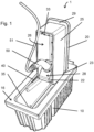
- the underground power supply system 1 is configured to charge an electric vehicle, and is configured to be arranged underground when in use. Therefore, the underground power supply system is configured to be arranged below street level, when a plug 50 has been installed in a power socket and charging of the vehicle has been started.
- the underground power supply system 1 comprises an underground casing 10 and a cover 20.
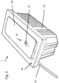
- the cover 20 is rotatable mounted in the underground casing 10 and movable between an opened position as shown in Figure 1 , and a closed position, as shown in Figure 2 .
- the underground casing 10 is configured to be installed underground at a depth that a top wall 16 of the underground casing 10 is at same level as the surrounding surface, such as the surrounding pavement.
- the cover 20 may be designed such that the top wall 16 of the casing 10 will support the cover 20 on the upper wall 29.
- the top side of the cover 20 may comprise a recess to receive a structure similar to the surrounding structure, for instance pavements stones corresponding to the stones of the surrounding pavement.
- the cover 20 is rotatable with respect to the underground casing 10 through a hinge 23, which is provided between the underground casing 10 and the cover 20.
- the cover 20 may be rotated around the hinge 23 when it is moved between the open and the closed position.
- the underground casing 10 comprises at its upper side an opening 13 that provides access to an interior of the underground casing 10.
- the cover 20 In the closed position, the cover 20 extends in a substantially horizontal position to cover substantially the whole opening 13. In the opened position of the cover 20, the interior of the underground casing 10 is accessible for the user.
- a spring 40 is provided to move the cover 20 from the closed position to the opened position.
- a gas damper 41 is provided between the underground casing 10 and the cover 20 for damping purposes.
- One end of the spring 40 is mounted on the interior of the underground casing 10 and the other end is attached to the cover 20.
- the spring 40 When the cover 20 is in the closed position, the spring 40 will be elongated and will bias the cover 20 to the open position. A lower remaining amount of pre-stress will be present in the spring 40 when the cover 20 is in the open position, which will keep the cover in the opened position.
- the force provided by the spring 40 is sufficient to automatically move the cover from the closed position to the opened position.
- other devices may be comprised to keep the cover 20 in the opened position.
- a permanent magnet for example, may be used to apply a required force to keep the cover 20 in the opened position.
- the cover 20 comprises a circumferential airtight wall 25 to form, together with an upper wall 29 an airtight compartment 26.
- An opening is present at the side of the airtight compartment 26 opposite to the upper wall 29 of the cover 20, through which access is provided to the airtight compartment 26, when the cover 20 is in the opened position.
- a power socket unit 22 is mounted in the airtight compartment 26.
- the power socket unit 22 is at least partly arranged in the airtight compartment 26.
- the power socket unit 22 comprises a power socket to connect a plug of a charging cable.
- the airtight compartment 26 is capable of holding a volume of air inside, when the cover 20 is in the closed position. This volume of air prevents water from entering the airtight compartment 26. The interior of the airtight compartment 26 will therefore not come into contact with water and the power socket unit 22, that is arranged inside the airtight compartment 26, will not short circuit as a result of water entering.
- the plug 50 and charging cable 51 are shown.
- FIG 2 it can be seen that when the cover 20 is in the closed position, the opening 13 is not fully covered by the cover 20 in order to allow passage of the charging cable 51 from the interior of the underground casing 10 to the outside.
- the cover 20 further comprises a reading device 37 in the top surface 21, as can be seen in Figure 2 , through which communication with the underground power supply system 1 by for example Bluetooth or Near Field Communication (NFC) is possible.
- NFC Near Field Communication
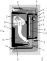
- Figures 3 and 4 respectively show a section view of the underground power supply system 1 with the cover 20 in closed and opened position.
- the underground casing 10 of the underground power supply system 1 comprises two casing compartments 11, 12, which are separated by a removable wall element 14.
- the first casing compartment 11 has an opening 13 in the top to provide access to the interior of the casing 10.
- the control unit 30 and the communication unit 34 are arranged within the second casing compartment 12.
- the second casing compartment 12 may, in other embodiments, also be arranged at other sides of the first casing compartment 11.
- a locking mechanism 33 is present to lock the cover 20 in the closed position with respect to the underground casing 10.
- the locking mechanism 33 is attached to cover 20.
- the locking mechanism 33 is configured to cooperate with a locking bracket 35 which is situated on the bottom of the first casing compartment 11. When the cover 20 moved into the closed position, the locking mechanism 33 locks into the locking bracket 35 to hold the cover 20 in the closed position.
- the locking mechanism 33 will have two major functions: it will, first, prevent unauthorized persons to gain access to the interior part of the underground power supply system 1. Secondly, it will hold the cover 20 in the closed position, despite the spring 40 applying a biasing force to the cover 20.
- the locking mechanism 33 is connected to the control unit 30 and can be activated to release the locking engagement with the locking bracket 35 by a release signal from the control unit 33.
- the control unit may provide a release signal when a user has requested the opening of the cover 20 in order to connect a vehicle to the underground power supply system 1.
- the user may request opening of the cover 20 using a remote device, such as a mobile telephone, connected to the internet.
- a remote device such as a mobile telephone
- the remote device may also be a remote control that directly communicates with the communication unit 34.
- the control unit 30 may receive the request from the reading device 37 that allows direct communication with a remote device, such as a card or mobile telephone.
- a water sensor 36 is arranged on the removable wall element 14.
- the water sensor 36 is provided to measure the water level in the first casing compartment 11. As a result of excessive rain or a high ground water level, water may accumulate inside the first casing compartment 11. This water level can be detected by the water sensor 36 and can be transmitted to the control unit 30, in order to provide information on the status of the underground power supply system 1.
- the airtight compartment 26 can be seen again.
- the power socket unit 22 is at least partly arranged.
- a tilting mechanism is arranged to rotate the power socket unit 22 between a position within the interior of the airtight compartment 26, as in Figure 4 , and a position in which the power socket unit extends at least partly from the interior of the airtight compartment 26 as in Figure 3 .
- the position of the power socket unit 22 with respect to the cover 20 will change as a function of the position of the cover 20 with respect to the casing 10.
- a rest 15 forces the power socket unit 22 in the interior of the airtight compartment 26.
- the power socket unit 22 When the cover 20 is in the open position, as in Figure 3 , the power socket unit 22 will, forced by gravitational forces, be rotated around hinge 27 to a position in which it at least partly extends from the interior of the airtight compartment 26.
- the top surface 28 of the power socket unit 22 will be parallel to the top wall 16 of the casing 10 for optimal ergonomics for the user, when the plug 50 is being installed in the power socket unit 22.
- the underground casing 1 and the cover 20 may be made from any suitable material such as metals, for example carbon and stainless steel or plastic materials.
- the underground power supply system 1 may release the locking mechanism 33 of the cover 20 from the casing 10 and the cover 20 will automatically be moved to the opened position by the spring 40.
- the power socket unit 22 will tilt at least partly out of the airtight compartment 26 in order to provide better access for the user to the power socket unit 22.
- the control unit 30 allows a current to flow to the power socket unit 22 and charging of the vehicle can start.
- the underground power supply system 1 When the charging of the vehicle has stopped or when the user decides to leave again from the underground power supply system 1, he will send a release signal to the underground power supply system 1.
- the underground power supply system 1 will release the locking mechanism 33 of the cover 20 from the casing 10 and the cover 20 will automatically be moved to the opened position by the spring 40.
- the power socket unit 22 will tilt again at least partly out of the airtight compartment 26 in order to provide better access for the user to the power socket unit 22.
- the user is then able to remove the plug 50 from the power socket unit 22. After removal of the plug 50, the user will move the cover 20 to the closed position, after which the charging procedure has been finished.
- the water sensor 36 will return a signal to the control unit 30.
- the control unit 30 may decide that charging of a vehicle, by means of the underground power supply system 1 is not safe. The control unit 30 will therefore prevent the locking mechanism 33 from unlocking the cover 20, and the underground power supply system 1 cannot be used to charge a vehicle.
- FIG 5 an alternative embodiment of the underground power supply system according to the invention is shown.
- the embodiment of the system 101 in figure 5 is substantially similar to that in figures 1 - 4 , except for that it only comprises a single casing compartment 111.
- the system 101 comprises a first airtight compartment 126, which is formed by a top wall formed by the cover 120 and the side walls 125, which are integrally formed with the cover 120.
- the power socket unit 122 is arranged at least partially in the first airtight compartment 126 and is rotatably mounted thereto.
- the system 101 comprises a second airtight compartment 160, which is configured to be mounted to a bottom 117 of the casing 110.
- the second airtight compartment 160 comprises side walls 161 and a top wall 162, which together define an interior 163 of the second airtight compartment 160.
- the interior 163 can be accessed through an opening, defined by the side walls 161, which abuts, in operating condition of the system 101, the bottom 117 of the casing 110.
- the second airtight compartment 160 is configured to hold a volume of air in its interior 163, to prevent water from flowing in.
- the control unit 130 is arranged in the interior 163 of the second airtight compartment 160 and is therefore, at least in the operating condition of the system 101, prevented from coming into contact with water.
- the control unit 130 comprises at least one connector 138, in which the control unit 130 is configured to receive a plug 140.
- the control unit 130 is, in the operating condition, electrically connected to cables 139, by means of the connector 138 and the plug 140, to provide current to the power socket unit 122.
- the cables 139 enter the interior 163 of the second airtight compartment 160 through a passage in one of the side walls 161 of the second airtight compartment 160.
- the passage is thereby arranged substantially lower than the control unit 130 to prevent the control unit 130 from coming into contact with water that might enter the second airtight compartment 160 through the passage.
- the second airtight compartment 160 is formed as an exchangeable module that can easily be taken out of the casing compartment 111. This allows for easy repair and/or replacement of the control unit 130 and other electronic components arranged in the second airtight compartment 160.
- a snap-fit connection device is provided to mount the second airtight compartment 160 on the bottom wall of the casing compartment 111.
- FIG. 6 shows the exchangeable second airtight compartment 160 separately.
- the second airtight compartment 160 can be completely taken out of the casing compartment 111 by releasing the snap-fit connection and pulling the plug 140 out of the connector 138. Thereafter, a new second airtight compartment 160 may be arranged in the casing compartment 111, by plugging plug 140 into connector 138 of the new second airtight compartment 160 and mounting the second airtight compartment 160 on the bottom wall using the snap-fit connection device.
- the system 1 further comprises a connection piece 170, which is configured to guide at least one of the cables 139 into the interior of the first airtight compartment 126.
- the connection piece 170 has a shape that substantially mates to that of at least one of the side walls 125 of the first airtight compartment 126.
- the connection piece 170 is mounted to that one of the side walls 125 by means of a snap-fit connection. As a result, the at least one cable 139 is guided into the first airtight compartment 126 along the side wall 125.
- connection piece 170 ensures an air impermeable passage of at least one cable 139 from the exterior to the interior of the first airtight compartment 126. This prevents air leakage from the interior of the first airtight compartment 126 to the exterior.
- the at least one cable 139 may as well be a wiring harness, comprising multiple cables, and tightly surrounded by the connection piece 170, such that no air can permeate through the connection piece 170 and leak from the interior to the exterior of the first airtight compartment 126.
- connection piece may be used to guide the cables 139 into the second airtight compartment 160.
Landscapes
- Engineering & Computer Science (AREA)
- Power Engineering (AREA)
- Transportation (AREA)
- Mechanical Engineering (AREA)
- Architecture (AREA)
- Civil Engineering (AREA)
- Structural Engineering (AREA)
- Charge And Discharge Circuits For Batteries Or The Like (AREA)
- Electric Propulsion And Braking For Vehicles (AREA)
Description
- The present invention relates to an underground power supply system, in particular an underground vehicle charging station, according to the preamble of
independent claim 1. The invention also relates to a method to supply an electric current to charge an electric vehicle with the use of an underground power supply system according to the preamble ofindependent claim 10. Such an underground vehicle charging station is known, for example, from European Patent ApplicationEP2640597 A2 . - The use of vehicles that contain an electric power unit becomes more popular lately. These vehicles, also known as electric vehicles EV and plug-in hybrid electric vehicles PHEV, rely on the usage of an electric motor as a means to transfer energy. Part of the required electrical energy is obtained by means of regenerative braking; other parts are obtained from the electrical grid. To charge the batteries in these vehicles, an interface is needed to present the electricity to the vehicle. Until now, most of these interfaces have arrived in the form of a charging station on street level, appearing for example like a pole in the sidewalk.
- Several underground vehicle charging stations are also known, such as for example in
WO2012104231 A2 , in which the charging station is positioned on a platform that is configured to move vertically in order to sink the charging station below the street level when not in use. A benefit of this submerged charging station is that the street scene is no longer exposed to these charging stations when not in use, and they can no longer be subject of vandalism and are exposed less to the outdoor climate. - A drawback of the known charging station is the complexity of the system. A large casing has to be submerged into the ground to house the charging station and all appliances. The lifting system, to raise the interface of the charging station to street level is also complex and therefore expensive. The underground casing is prone to flooding with water, for example by a high ground water level or by excessive rain. The water in the casing is likely to cause short circuiting in the charging station.
- United States patent application
US 5 342 993 A discloses an electric outlet apparatus for outdoor use, including a housing having a top portion and an opening in the top portion, a receptacle panel structure having a first face and including a receptacle circuit, a receptacle mounted in the first face of the receptacle panel structure, a mechanism for movably connecting the panel to the housing so that the panel can move between a position, wherein the panel first face is directed essentially downward inside the housing and an open position wherein the panel extends out of the top opening, and a substantially air tight compartment defined below the first face of the receptacle panel structure for preventing any water collected within the housing from rising to meet the receptacle panel structure. - Dutch patent
NL 1 007 973 C2 - European
patent application EP 2 400 614 A1 discloses a lifting system for a distributor of an under-floor system, which system has a distributor moving up or down and pushing a plunger, which is arranged at a lower side of a shaft cover. The distributor is detached from the plunger and freely accessible when lower edge of the plunger reaches an upper edge of a shaft, through a telescopic function of the shaft cover with the plunger driven upwards. The shaft is made of plastic or stainless steel. The cover is linearly driven from the shaft, where the system moves in and out by spindle or hydraulic pressure. - Finally, United States patent application
US 5 755 582 A discloses a retractable door stop security device or utility box, which is mounted in a floor or other flat mounting surface and which includes a housing with a flange plate, which is mounted in an opening in the mounting surface. A retractable member is provided within the housing which alternates between a raise position and a lower position. By pressing downwardly on the top of the retractable member, a latching mechanism is released, allowing the spring biased retractable member to move to the raised position. The retractable member is lowered by applying a force sufficient to counteract the action of the spring and move the member into the housing, whereupon the latch mechanism re-engages the retractable member to retain it in the lower position. - It is an object of the invention to provide an improved underground power supply system in which one or more of the above drawbacks are eliminated or at least partly reduced.
- The present invention provides an underground power supply system as claimed in
claim 1. - In an embodiment, the underground power supply system is an underground vehicle charging station that is used to provide an electric current to an electric vehicle in order to charge the batteries of the electric vehicle.
- The underground power supply system comprises a casing comprising an opening at the upper side, where a cover is attached to the casing in such a way that when the cover is in the closed position, the opening in the casing is closed at least partly. An airtight compartment is situated at the inner surface of the cover that faces the interior of the casing when the cover is in closed position. This airtight compartment comprises one or more side walls and has an opening at the side of the airtight compartment opposite of the inner surface and is facing an interior of the casing.
- A power socket unit is arranged at least partly in this airtight compartment, such that the power socket unit is accessible through the opening in the airtight compartment. An actuating element is arranged in the underground power supply system, configured to move the cover from a closed position to an open position.
- An advantage of the system according to the invention is the presence of the airtight compartment in the interior of the cover. This airtight compartment functions like a diving-bell and is capable, when the opening is facing downward, to hold a volume of air inside. When the casing happens to flood as a result of excessive rain or a high ground water level, the volume of air inside the airtight compartment will prevent water from entering therein. The airtight compartment therefore needs to be airtight to hold the air inside. The power socket unit is situated at least partly in the interior of the airtight compartment. It will, as a result of the trapped volume of air, be surrounded by air alone and short circuiting, as a result of water entering the power socket unit, will be prevented.
- Preferably, the walls of the airtight compartment do not comprise any holes, which define a passage between an interior and an exterior of the compartment. In particular, the compartment does not comprise any holes through its side walls and top wall to provide an opening to receive cable or the like that run from an interior to the exterior of the compartment.
- A cable may run from the power socket unit towards the control unit, to supply the power socket unit with an electric current. When an electric vehicle is charged, a plug of a charging cable is connected to the power socket unit. The other end of the charging cable is coupled to the vehicle. After charging the plug may be disconnected from the power socket unit.
- The airtight compartment is designed so that both the power socket unit and the plug are captured in the volume of air, leaving only the cables to be exposed to the water, if present. Since cables are designed to be used in wet environments, the risk of having short circuiting in the power socket unit as a result of water entering is eliminated.
- In an embodiment, the cable may enter the interior of the airtight compartment through a hole in a side wall. However, in another embodiment, in which the airtight compartment is free of any holes in the walls, the cable enters the airtight compartment through the opening of the airtight compartment and runs, at least partially, along an inner surface of at least one of the side walls, facing the interior of the airtight compartment and along an outer surface of the at least one of the side walls, at the exterior of the compartment.
- It has been found that the cables, which are used to electrically connect the power socket unit and the control unit, may be permeable for air. In particular, cable jackets may be porous and provide migration paths for gasses to permeate through the cable. Air, that is supposed to be retained within the airtight compartment of the system, could, as a result, leak out of the compartment, allowing water to enter the compartment.
- A connection piece may therefore be provided through which the cables enter the interior of the airtight compartment. The connection piece may be arranged at a side wall of the airtight compartment, adjacent the opening. The connection piece is non-permeable for air, such that the airtightness of the airtight compartment is maintained.
- During manufacturing of the connection piece, the cable jacket is, at least partially at the section of the cable which is supposed to be within the connection piece, removed, such that wires of the cable become exposed. The wires are generally made of a metal, preferably copper, and are not permeable for air. The wires are then guided through a mould, after which resin or molten plastic is casted into the mould. The resin or plastic thereby tightly enclose the wires, such that the wires cannot contact each other within the connection piece, to prevent short-circuiting, and that no air can permeate through the connection piece, along the wires.
- In an embodiment, the connection piece is configured to be releasably mounted to one of the side walls of the airtight compartment. The connection piece may, for example, be mounted to the side wall by means of a snap-fit mount. This snap-fit mount allows for easy installation and removal of the connection piece, without the need for tools to be used.
- In this embodiment, preferably, connectors may be provided with which the parts of the cable inside the connection piece may be uncoupled from the parts of the cable that are arranged outside the connection piece. The connection piece can thereby be removed as a whole, without having to remove the entire cable as well. In case one connection piece then turns out to leak, for example, it may be replaced with another connection piece swiftly and relatively cheap.
- In an embodiment, multiple cables may be bonded together to form a wiring harness, which is at least partially arranged in the connection piece to enter the interior of the airtight compartment, without leaking air. The multiple cables are preferably arranged in a row parallel to each other.
- The opening in the casing is covered by the cover at least partly. When the cover covers the opening only partly, water is not fully prevented from entering the casing. If the casing happens to flood with water, it is desirable to remove the water from the interior of the casing. The casing could therefore comprise one or more holes that penetrate its walls and form a connection between the interior and the exterior of the casing and thereby allow excessive water to be drained from the casing. A pump can be arranged as well to remove excessive water from the interior of the casing to the exterior. The casing is equipped with a sensor that measures the water level in the casing and communicates this signal back to the control unit of the underground power supply system.
- In the known underground power supply system, an actuator is used to lift the power socket unit from a position in the casing to a position on street level, where the power socket unit was accessible to the user. An example of this complex and expensive setup is shown in
Figures 1A and 1B ofWO2012104231 A2 . The present invention also comprises an actuation element to make the power socket unit accessible to the user, but instead of lifting the power socket unit above street level, the cover is moved between an open and closed position. - The present underground power supply system comprises a cover, rotatable with respect to the casing around an axis along a side of the opening. In this embodiment, the airtight compartment will rotate along with the cover, by which the opening of the airtight compartment is presented to the user such that the power socket unit is accessible for the user. Especially, the rotational opening of the cover is a less complex solution to the found drawbacks of the complex lifting system of the power socket unit from the ground as in
WO2012104231 A2 . - The power socket unit comprises one or more power sockets. Two or more power sockets allow simultaneous connection of two or more plugs in the power socket unit for simultaneous charging of two or more vehicles.
- In an embodiment, the power socket unit is arranged on a tilting mechanism mounted in the airtight compartment to allow the power socket unit to be moved between the charging position, in which the power socket unit at least partly extends out of the airtight compartment, and the retracted position, in which the power socket unit is arranged in the airtight compartment.
- An advantage of this movement by the tilting mechanism is the increased accessibility for the user to the power socket unit. When the cover is opened, the power socket unit is partly moved out of the airtight compartment into a charging position to allow better access to the power socket unit for the user. When the cover is closed, the power socket unit will be arranged in a retracted position. To hold the power socket unit in the retracted position a rest may be provided. The movement of the power socket unit is enabled by a tilting mechanism, which is configured to allow rotation of the power socket unit with respect to the airtight compartment. The rotation of this tilting mechanism will be coupled to the opening and closing of the cover and no actuator mechanism is required to individually rotate the tilting mechanism. The rotation is preferably caused by gravitation, but also other devices such as springs and magnets may be provided to cause this rotation of the power socket unit.
- In the present power supply system, the actuator mechanism to move the cover to the open position is a spring element. In this embodiment, the spring element is mounted on the cover and the casing. When the cover is in closed position, the spring is loaded in tension. The cover will, as a result of this pre-tension, move to the open position. When the cover is in the open position, the tensile load in the spring would have decreased to an extent that the cover will remain in the open position. For example, a coiled or spiral spring can be provided, combined with a gas damper for damping purposes. The coiled spring will automatically move the cover to the open position without external actuation, while the damper decreases the speed at which the cover is moved to the open position.
- To prevent the cover from moving to the open position at any time, a locking mechanism is provided. This locking mechanism is able to lock the cover with respect to a locking bracket in the casing, keeping the cover in the closed position, and is able to unlock the cover, allowing the spring element to move the cover to the open position. This locking mechanism may prevent the underground power supply system, and especially the power socket unit, to be accessible for the public. Only authorized users will be able to unlock the cover, which will decrease the risk of vandalism or theft of electricity.
- In an embodiment, the locking mechanism is configured to unlock the cover upon receipt of a release signal from the control unit, such that the actuation element will automatically move the cover to the opened position. In order for only authorized users to use the underground power supply system, the locking mechanism must be able to be opened by a release signal from those users.
- In an embodiment, the underground power supply system comprises a communication device to communicate with an external communication device, for example a mobile telephone, remote control unit, card, etc.
- The communication device may be configured for direct communication through for example Bluetooth or Near Field Communication (NFC) in for example the cover, while in another embodiment, a mobile device, for example a mobile telephone with an app installed, can communicate indirectly with a communication unit through the internet. The communication unit is able to send this signal to the control unit, which is able to verify the release signal and capable of sending a signal to the locking mechanism to unlock the cover. Using this remote way of opening the cover, the system is able to know which user uses the system.
- It is remarked that the system may comprise mechanical locking/unlocking with a dedicated tool. This dedicated tool can be used to unlock the cover, when for example no electricity is provided to the underground power supply system or when there is a malfunctioning of the system, for example by the communication unit.
- In an embodiment, the underground power supply system is an underground vehicle charging station, comprising a control unit configured to monitor and control the electric current towards the power socket unit, wherein the control unit is preferably configured to only charge the vehicle when the cover is in the closed position.
- The airtight compartment, in which the power socket unit houses, is designed in a way that the cover can be closed when the charging cable is installed in the power socket unit. This is an advantage over the known system, since in that system, the power socket unit had to remain on street level during charging. The advantage of having the power socket unit submerged in the casing during charging is that the cable cannot be removed from the power socket unit during charging of the vehicle without the user's intention, since the cover will be locked. The power socket unit will also harm the street scene to a lower extent, since only the charging cable will be visible and not the entire power socket unit.
- The cover closes the opening in the casing at least partly, so that in a possible embodiment, the cable towards the vehicle can run through a part of the opening not covered by the cover in the closed position from the power socket unit towards the vehicle.
- A second sensor can be arranged in the casing, with which can be validated whether the cover is in the open or in the closed position. This second sensor is able to communicate with the control unit in order to start charging of the vehicle when the cover is in the closed position. It may also possible that the user first has to confirm the beginning of the charging process on a remote device.
- In an embodiment, the control unit is configured to send a signal to the locking mechanism to lock the cover when the cover is moved into the closed position.
- In an embodiment, the casing is composed of two or more separate casing compartments. For example, the underground power supply system may comprise one casing compartment to receive the airtight compartment in the closed position and another casing compartment to receive the control unit and communication unit. Only one casing compartment will comprise the opening that provides access to the interior of the casing compartment. A cover may be arranged at least partly over this opening and the power socket unit is attached to this cover.
- The casing compartment is accessible when the user intends to charge the vehicle. However, the control unit for example, does not necessarily need to be accessible for the user. When the casing is separated into multiple casing compartments, this control unit and possible other components of the system that do not need to be used directly by the user, such as the communication unit, can be placed into a separate casing compartment. A second locking mechanism can be present to allow only access to those components for authorized people, such as mechanics for servicing and repair. A first advantage is that all components placed in this second casing compartment, are less prone to, for example, sabotage. Since these components generally not need to be accessed as often as the power socket unit, another advantage is that a second cover, which will close this casing compartment, can be made airtight, protecting the interior.
- In an embodiment, the system comprises a second airtight compartment, which is configured to be arranged at a bottom of the casing. The second airtight compartment comprises, just like the first airtight compartment, side walls and a top wall, which together define an interior of the second airtight compartment. At least the side walls and the top wall of the second airtight compartment are non-permeable for air and are thus airtight.
- The interior can be accessed through an opening that is defined by the side walls as well and is arranged opposite to the top wall. The second airtight compartment is configured to be mounted on a bottom of the casing, such that its opening is closed by the bottom of the casing and that the top wall is set away from the bottom.
- Preferably, the side walls and the top wall of the second airtight compartment form an integral part in order to achieve optimal airtightness of the second airtight compartment.
- The second airtight compartment is configured to keep a volume of air in its interior to prevent flooding of the interior with water.
- The control unit is arranged in the interior of the second airtight compartment and is thereby prevented from coming into contact with water. The control unit may be mounted to the top wall of the second airtight compartment, thereby facing the opening.
- In an embodiment, the second airtight compartment is formed as an exchangeable module. This allows for easy repair and/or replacement of the control unit and other electronic components arranged in the second airtight compartment. In order to make the second airtight compartment exchangeable a releasable snap-fit connection device may be provided to mount the second airtight compartment on for example the bottom wall of the casing of the system. Any other device to releasably mount the second airtight compartment in the system may also be used. A lock device may be provided to lock the second airtight compartment in the mounted position in order to prevent that unauthorized persons take the second air tight compartment out of the system.
- The control unit may comprise at least one connector in which a plug of a cable can be releasably plugged to obtain an electrical connection between the control unit and the cable. An advantage of this releasable connection is that, in case the control unit may break down, the second airtight compartment can be removed, the at least one connector can be released and the control unit can be removed from the compartment. This allows for swift and easy exchange of control units in case of a breakdown.
- The invention further provides a method to provide an electric current to charge an electric vehicle, using an underground power supply system, in particular an underground vehicle charging station, as described any of the claims 1-9, comprising the steps of:
- sending a loading request to the underground power supply system,
- moving, by the actuation element, the cover to the opened position and exposing the power socket unit from an underground casing to the user,
- attaching a charging cable to the power socket unit and the vehicle,
- charging the vehicle by delivering an electric current to the power socket unit, and
- removing the charging cable from the power socket unit and the vehicle when the underground power supply system has finished charging.
- In an embodiment of the method, during the step of moving the cover to the opened position, the power socket unit moves from the retracted position, in which the power socket unit is arranged in the airtight compartment to the charging position, in which the power socket unit at least partly extends out of the airtight compartment, thereby allowing better access to the power socket unit by the user. The movement of the power socket unit at least partly out of the airtight compartment increases the accessibility of the power socket unit to the user.
- In an embodiment of the method, an active request may be sent by the user to the underground power supply system to allow the system to start supplying electricity to the power socket unit. This request may function as a confirmation that all appliances, like the plug for example, have been installed properly.
- In an embodiment, the method comprises the step of sending a request, by the user, to the underground power supply system to unlock the cover in order to allow opening of the cover and removal of the charging cable from the power socket unit.
- In an embodiment, the method comprises, after the step of removing the charging cable from the power socket unit, moving, by the user, the cover into the closed position, wherein closure of the cover is preferably confirmed by a control unit.
- According to the present invention, the control unit prevents the power socket unit to be moved between the retracted position and the accessible position, when a water level sensor in the casing measures a water level in the casing that exceeds a predetermined maximum level.
- The water level in the casing can be measured by a sensor. When the water level in the casing is too high, above a certain predetermined maximum value, the control unit can decide not to unlock the cover when the user sends a signal to unlock the cover. The airtight compartment which houses the power socket unit and a plug from the charging cable in a volume of air, can pick up water when the cover is moved to the open position when the water level is too high, and therefore cause short circuiting in the system after all.
- When the control unit prevents the locking mechanism from unlocking the cover, the water has time to flow out of the casing and/or a pump can be activated to remove water from the casing, after which the cover can be moved to the open position after all.
- An embodiment of the invention will now be described, by way of example only, with reference to the accompanying schematic drawings in which:
-
Figure 1 shows a plan view of the underground power supply system with the cover in the opened position; -
Figure 2 shows a plan view of the underground power supply system with the cover in the closed position; -
Figure 3 shows a section view of the underground power supply system with the cover in the closed position; -
Figure 4 shows a section view of the underground power supply system with the cover in the open position; -
Figure 5 shows a section view of an alternative embodiment of the underground power supply system; and -
Figure 6 shows a section view of the second airtight compartment module. - The underground
power supply system 1 is configured to charge an electric vehicle, and is configured to be arranged underground when in use. Therefore, the underground power supply system is configured to be arranged below street level, when aplug 50 has been installed in a power socket and charging of the vehicle has been started. - The underground
power supply system 1 comprises anunderground casing 10 and acover 20. Thecover 20 is rotatable mounted in theunderground casing 10 and movable between an opened position as shown inFigure 1 , and a closed position, as shown inFigure 2 . - The
underground casing 10 is configured to be installed underground at a depth that atop wall 16 of theunderground casing 10 is at same level as the surrounding surface, such as the surrounding pavement. In an embodiment, thecover 20 may be designed such that thetop wall 16 of thecasing 10 will support thecover 20 on theupper wall 29. - The top side of the
cover 20 may comprise a recess to receive a structure similar to the surrounding structure, for instance pavements stones corresponding to the stones of the surrounding pavement. - The
cover 20 is rotatable with respect to theunderground casing 10 through ahinge 23, which is provided between theunderground casing 10 and thecover 20. Thecover 20 may be rotated around thehinge 23 when it is moved between the open and the closed position. - The
underground casing 10 comprises at its upper side anopening 13 that provides access to an interior of theunderground casing 10. In the closed position, thecover 20 extends in a substantially horizontal position to cover substantially thewhole opening 13. In the opened position of thecover 20, the interior of theunderground casing 10 is accessible for the user. - A
spring 40 is provided to move thecover 20 from the closed position to the opened position. In the shown embodiment, agas damper 41 is provided between theunderground casing 10 and thecover 20 for damping purposes. - One end of the
spring 40 is mounted on the interior of theunderground casing 10 and the other end is attached to thecover 20. When thecover 20 is in the closed position, thespring 40 will be elongated and will bias thecover 20 to the open position. A lower remaining amount of pre-stress will be present in thespring 40 when thecover 20 is in the open position, which will keep the cover in the opened position. The force provided by thespring 40 is sufficient to automatically move the cover from the closed position to the opened position. - In a further embodiment, other devices may be comprised to keep the
cover 20 in the opened position. A permanent magnet, for example, may be used to apply a required force to keep thecover 20 in the opened position. - The
cover 20 comprises a circumferentialairtight wall 25 to form, together with anupper wall 29 anairtight compartment 26. An opening is present at the side of theairtight compartment 26 opposite to theupper wall 29 of thecover 20, through which access is provided to theairtight compartment 26, when thecover 20 is in the opened position. - In the
airtight compartment 26, apower socket unit 22 is mounted. Thepower socket unit 22 is at least partly arranged in theairtight compartment 26. Thepower socket unit 22 comprises a power socket to connect a plug of a charging cable. Theairtight compartment 26 is capable of holding a volume of air inside, when thecover 20 is in the closed position. This volume of air prevents water from entering theairtight compartment 26. The interior of theairtight compartment 26 will therefore not come into contact with water and thepower socket unit 22, that is arranged inside theairtight compartment 26, will not short circuit as a result of water entering. - As an indication, the
plug 50 and chargingcable 51 are shown. InFigure 2 , it can be seen that when thecover 20 is in the closed position, theopening 13 is not fully covered by thecover 20 in order to allow passage of the chargingcable 51 from the interior of theunderground casing 10 to the outside. Thecover 20 further comprises areading device 37 in thetop surface 21, as can be seen inFigure 2 , through which communication with the undergroundpower supply system 1 by for example Bluetooth or Near Field Communication (NFC) is possible. When a signal would be applied to thereading device 37, for example by means of a card or a mobile telephone, the undergroundpower supply system 1 recognizes the user and allows thecover 20 to be moved to the opened position. -
Figures 3 and4 respectively show a section view of the undergroundpower supply system 1 with thecover 20 in closed and opened position. Theunderground casing 10 of the undergroundpower supply system 1 comprises twocasing compartments removable wall element 14. - The
first casing compartment 11 has anopening 13 in the top to provide access to the interior of thecasing 10. Within thesecond casing compartment 12, thecontrol unit 30 and thecommunication unit 34 are arranged. Thesecond casing compartment 12 may, in other embodiments, also be arranged at other sides of thefirst casing compartment 11. - In the shown embodiment, a
locking mechanism 33 is present to lock thecover 20 in the closed position with respect to theunderground casing 10. Thelocking mechanism 33 is attached to cover 20. Thelocking mechanism 33 is configured to cooperate with a lockingbracket 35 which is situated on the bottom of thefirst casing compartment 11. When thecover 20 moved into the closed position, thelocking mechanism 33 locks into the lockingbracket 35 to hold thecover 20 in the closed position. - The
locking mechanism 33 will have two major functions: it will, first, prevent unauthorized persons to gain access to the interior part of the undergroundpower supply system 1. Secondly, it will hold thecover 20 in the closed position, despite thespring 40 applying a biasing force to thecover 20. Thelocking mechanism 33 is connected to thecontrol unit 30 and can be activated to release the locking engagement with the lockingbracket 35 by a release signal from thecontrol unit 33. The control unit may provide a release signal when a user has requested the opening of thecover 20 in order to connect a vehicle to the undergroundpower supply system 1. - For example, the user may request opening of the
cover 20 using a remote device, such as a mobile telephone, connected to the internet. In that case thecontrol 30 unit will also have to be connected to the internet. The remote device may also be a remote control that directly communicates with thecommunication unit 34. As an alternative, thecontrol unit 30 may receive the request from thereading device 37 that allows direct communication with a remote device, such as a card or mobile telephone. - In
Figures 3 and4 , awater sensor 36 is arranged on theremovable wall element 14. Thewater sensor 36 is provided to measure the water level in thefirst casing compartment 11. As a result of excessive rain or a high ground water level, water may accumulate inside thefirst casing compartment 11. This water level can be detected by thewater sensor 36 and can be transmitted to thecontrol unit 30, in order to provide information on the status of the undergroundpower supply system 1. - In
Figures 3 and4 , theairtight compartment 26 can be seen again. Within thisairtight compartment 26, thepower socket unit 22 is at least partly arranged. A tilting mechanism is arranged to rotate thepower socket unit 22 between a position within the interior of theairtight compartment 26, as inFigure 4 , and a position in which the power socket unit extends at least partly from the interior of theairtight compartment 26 as inFigure 3 . It can be seen that the position of thepower socket unit 22 with respect to thecover 20 will change as a function of the position of thecover 20 with respect to thecasing 10. When thecover 20 is in the closed position, a rest 15 forces thepower socket unit 22 in the interior of theairtight compartment 26. When thecover 20 is in the open position, as inFigure 3 , thepower socket unit 22 will, forced by gravitational forces, be rotated aroundhinge 27 to a position in which it at least partly extends from the interior of theairtight compartment 26. - In an alternative embodiment, the
top surface 28 of thepower socket unit 22 will be parallel to thetop wall 16 of thecasing 10 for optimal ergonomics for the user, when theplug 50 is being installed in thepower socket unit 22. - The
underground casing 1 and thecover 20 may be made from any suitable material such as metals, for example carbon and stainless steel or plastic materials. - When a user would like to charge his vehicle he may for example first locate the nearest underground
power supply system 1 on a map on his mobile telephone. He will drive towards the nearest undergroundpower supply system 1 and will park close to it. - To open the
cover 20, he may send a release signal to the undergroundpower supply system 1, for example by means of a mobile telephone. The undergroundpower supply system 1 may release thelocking mechanism 33 of thecover 20 from thecasing 10 and thecover 20 will automatically be moved to the opened position by thespring 40. During this rotating movement of thecover 20, thepower socket unit 22 will tilt at least partly out of theairtight compartment 26 in order to provide better access for the user to thepower socket unit 22. - The user can then plug the
plug 50, with the chargingcable 51 attached into the power socket in thepower socket unit 22. When the plug is placed in the power socket, thecover 20 can be moved to the closed position, whereby thepower socket unit 22, with theplug 50 and chargingcable 51 attached, will tilt back in the retracted position within theairtight compartment 26. A second sensor will validate whether thecover 20 is in the closed position. As soon as it is conformed that thecover 20 is in the closed position, thecontrol unit 30 allows a current to flow to thepower socket unit 22 and charging of the vehicle can start. - When the charging of the vehicle has stopped or when the user decides to leave again from the underground
power supply system 1, he will send a release signal to the undergroundpower supply system 1. The undergroundpower supply system 1 will release thelocking mechanism 33 of thecover 20 from thecasing 10 and thecover 20 will automatically be moved to the opened position by thespring 40. Thepower socket unit 22 will tilt again at least partly out of theairtight compartment 26 in order to provide better access for the user to thepower socket unit 22. The user is then able to remove theplug 50 from thepower socket unit 22. After removal of theplug 50, the user will move thecover 20 to the closed position, after which the charging procedure has been finished. - In the case that the
first casing compartment 11 is filled substantially with water, thewater sensor 36 will return a signal to thecontrol unit 30. Depending on the height of the water, thecontrol unit 30 may decide that charging of a vehicle, by means of the undergroundpower supply system 1 is not safe. Thecontrol unit 30 will therefore prevent thelocking mechanism 33 from unlocking thecover 20, and the undergroundpower supply system 1 cannot be used to charge a vehicle. - In
figure 5 , an alternative embodiment of the underground power supply system according to the invention is shown. The embodiment of thesystem 101 infigure 5 is substantially similar to that infigures 1 - 4 , except for that it only comprises asingle casing compartment 111. - The
system 101 comprises a firstairtight compartment 126, which is formed by a top wall formed by thecover 120 and theside walls 125, which are integrally formed with thecover 120. Thepower socket unit 122 is arranged at least partially in the firstairtight compartment 126 and is rotatably mounted thereto. - The
system 101 comprises a secondairtight compartment 160, which is configured to be mounted to abottom 117 of thecasing 110. The secondairtight compartment 160 comprisesside walls 161 and atop wall 162, which together define an interior 163 of the secondairtight compartment 160. The interior 163 can be accessed through an opening, defined by theside walls 161, which abuts, in operating condition of thesystem 101, thebottom 117 of thecasing 110. - The second
airtight compartment 160 is configured to hold a volume of air in its interior 163, to prevent water from flowing in. Thecontrol unit 130 is arranged in theinterior 163 of the secondairtight compartment 160 and is therefore, at least in the operating condition of thesystem 101, prevented from coming into contact with water. - The
control unit 130 comprises at least oneconnector 138, in which thecontrol unit 130 is configured to receive aplug 140. Thecontrol unit 130 is, in the operating condition, electrically connected tocables 139, by means of theconnector 138 and theplug 140, to provide current to thepower socket unit 122. - In the embodiment of the
system 1, thecables 139 enter theinterior 163 of the secondairtight compartment 160 through a passage in one of theside walls 161 of the secondairtight compartment 160. The passage is thereby arranged substantially lower than thecontrol unit 130 to prevent thecontrol unit 130 from coming into contact with water that might enter the secondairtight compartment 160 through the passage. - The second
airtight compartment 160 is formed as an exchangeable module that can easily be taken out of thecasing compartment 111. This allows for easy repair and/or replacement of thecontrol unit 130 and other electronic components arranged in the secondairtight compartment 160. In order to make the secondairtight compartment 160 exchangeable a snap-fit connection device is provided to mount the secondairtight compartment 160 on the bottom wall of thecasing compartment 111. -
Figure 6 shows the exchangeable secondairtight compartment 160 separately. When there is for example an electronic failure of the control unit, the secondairtight compartment 160 can be completely taken out of thecasing compartment 111 by releasing the snap-fit connection and pulling theplug 140 out of theconnector 138. Thereafter, a new secondairtight compartment 160 may be arranged in thecasing compartment 111, by pluggingplug 140 intoconnector 138 of the new secondairtight compartment 160 and mounting the secondairtight compartment 160 on the bottom wall using the snap-fit connection device. - The
system 1 further comprises aconnection piece 170, which is configured to guide at least one of thecables 139 into the interior of the firstairtight compartment 126. Theconnection piece 170 has a shape that substantially mates to that of at least one of theside walls 125 of the firstairtight compartment 126. Theconnection piece 170 is mounted to that one of theside walls 125 by means of a snap-fit connection. As a result, the at least onecable 139 is guided into the firstairtight compartment 126 along theside wall 125. - The
connection piece 170 ensures an air impermeable passage of at least onecable 139 from the exterior to the interior of the firstairtight compartment 126. This prevents air leakage from the interior of the firstairtight compartment 126 to the exterior. The at least onecable 139 may as well be a wiring harness, comprising multiple cables, and tightly surrounded by theconnection piece 170, such that no air can permeate through theconnection piece 170 and leak from the interior to the exterior of the firstairtight compartment 126. - It is remarked that a similar connection piece may be used to guide the
cables 139 into the secondairtight compartment 160.
Claims (14)
- An underground power supply system (1,101), in particular an underground vehicle charging station, comprising:- a casing (10,110), to be arranged underground, comprising an opening (13) at the upper side,- a power socket unit (22,122), wherein the power socket unit is movable between a retracted position, in which the power socket unit is arranged within the casing and an accessible position, in which the power socket unit is accessible for a user to connect a charging cable (51), and- an actuating element to move the power socket unit between the retracted and accessible position,- a cover (20,120) attached to the casing and rotatable with respect to the casing around an axis along a side of the opening between an opened and a closed position, wherein, in the closed position, the cover covers the opening of the casing at least partly and an inner surface of the cover faces an interior of the casing, and- an airtight compartment (26,126,160) arranged at the inner surface of the cover, which is configured to rotate along with the cover and which has a second opening at a side of the airtight compartment opposite to the inner surface,wherein the power socket unit is at least in the closed position of the cover arranged in the airtight compartment, to prevent the power socket unit from getting into contact with water, and wherein the power socket unit is accessible for the user when the cover is arranged in the opened position,wherein the actuating element is configured to move the cover from the closed position to the opened position to move the power socket unit from the retracted to the accessible position, wherein the actuator element is a spring element (40), arranged to bias the cover to the opened position,wherein the underground power supply system comprises a locking mechanism (33) configured to lock the cover in the closed position and to unlock the cover to allow the spring element to move the cover in the opened position, and wherein the underground power supply system comprises a control unit (30,130) configured to control the locking mechanism,wherein the system comprises a sensor (36) that is configured to measure a water level in the casing and to communicate this signal to the control unit, andwherein the control unit is configured to prevent the power socket unit to be moved between the retracted position and the accessible position, when the water level sensor in the casing measures a water level in the casing that exceeds a predetermined maximum level.
- The underground power supply system according to claim 1, wherein the power socket unit is arranged on a tilting mechanism mounted in the airtight compartment to allow the power socket unit to be moved between the charging position, in which the power socket unit at least partly extends out of the airtight compartment, and the retracted position, in which the power socket unit is arranged in the airtight compartment.
- The underground power supply system according to claim 1 or 2, wherein the locking mechanism is configured to unlock the cover upon receipt of a release signal from the control unit, such that the actuation element will automatically move the cover to the opened position.
- The underground power supply system according to any of the claims 1-3, wherein the control unit is configured to send a signal to the locking mechanism to lock the cover when the cover is moved into the closed position.
- The underground power supply system according to any of the preceding claims, wherein the underground power supply system is an underground vehicle charging station, comprising a control unit configured to monitor and control the electric current towards the power socket unit, wherein the control unit is preferably configured to only charge the vehicle when the cover is in the closed position.
- The underground power supply system according to any of the preceding claims, wherein the underground power supply system comprises two or more casing compartments (11,12,111).
- The underground power supply system according to any of the preceding claims, wherein the underground power supply system comprises a communication device (34) to communicate with an external communication device.
- The underground power supply system according to any of the preceding claims, wherein the walls (25,29) of the airtight compartment are free of holes, which define a passage between an interior and an exterior of the compartment
- The underground power supply system according to the preceding claim, wherein the system comprises a connection piece (170), through which cables (139) enter the interior of the airtight compartment from an exterior of the airtight compartment, wherein the connection piece is non-permeable for air, and wherein the connection piece optionally has a shape that mates with a side wall of the compartment, such that the connection piece can be releasably connected to the side wall by a snap-fit connection.
- A method to provide an electric current to charge an electric vehicle, using an underground power supply system as described in the previous claims, comprising the steps of:sending a loading request to the underground power supply system,moving, by the actuation element, the cover to the opened position and exposing the power socket unit from an underground casing to the user,attaching a charging cable to the power socket unit and the vehicle,charging the vehicle by delivering an electric current to the power socket unit, andremoving the charging cable from the power socket unit and the vehicle when the underground power supply system has finished charging,wherein the control unit prevents the power socket unit to be moved between the retracted position and the accessible position, when a water level sensor in the casing measures a water level in the casing that exceeds a predetermined maximum level.
- The method to provide an electric current to charge an electric vehicle according to claim 10, wherein during moving the cover to the opened position, the power socket unit moves from the retracted position, in which the power socket unit is arranged in the airtight compartment to the charging position, in which the power socket unit at least partly extends out of the airtight compartment, thereby allowing better access to the power socket unit by the user.
- The method to provide an electric current to charge an electric vehicle according to claim 10 or 11, wherein the method comprises the step of sending a request, by the user, to the underground power supply system to unlock the cover in order to allow opening of the cover and removal of the charging cable from the power socket unit.
- The method to provide an electric current to charge an electric vehicle according to any of the claims 10-12, comprising, after the step of removing the charging cable from the power socket unit, moving, by the user, the cover into the closed position, wherein closure of the cover is preferably confirmed by a control unit.
- The method to provide an electric current to charge an electric vehicle according to claim 10-13, wherein the user, prior to sending the request for loading to the system, can display a map of the locations of all underground power supply systems on the remote device.
Applications Claiming Priority (2)
| Application Number | Priority Date | Filing Date | Title |
|---|---|---|---|
| NL2015564A NL2015564B1 (en) | 2015-10-05 | 2015-10-05 | Underground power supply system, in particular an underground vehicle charging station and a method to charge an electric vehicle. |
| PCT/NL2016/050689 WO2017061863A1 (en) | 2015-10-05 | 2016-10-05 | Underground power supply system, in particular an underground vehicle charging station and a method to charge an electric vehicle |
Publications (3)
| Publication Number | Publication Date |
|---|---|
| EP3360211A1 EP3360211A1 (en) | 2018-08-15 |
| EP3360211C0 EP3360211C0 (en) | 2023-06-07 |
| EP3360211B1 true EP3360211B1 (en) | 2023-06-07 |
Family
ID=55178279
Family Applications (1)
| Application Number | Title | Priority Date | Filing Date |
|---|---|---|---|
| EP16784993.4A Active EP3360211B1 (en) | 2015-10-05 | 2016-10-05 | Underground power supply system, in particular an underground vehicle charging station and a method to charge an electric vehicle |
Country Status (4)
| Country | Link |
|---|---|
| EP (1) | EP3360211B1 (en) |
| ES (1) | ES2949046T3 (en) |
| NL (1) | NL2015564B1 (en) |
| WO (1) | WO2017061863A1 (en) |
Cited By (7)
| Publication number | Priority date | Publication date | Assignee | Title |
|---|---|---|---|---|
| US20220126684A1 (en) * | 2019-01-22 | 2022-04-28 | Daimler Ag | Charging Connection Device for a Vehicle |
| FR3150052A1 (en) * | 2023-06-14 | 2024-12-20 | Psa Automobiles Sa | Device for housing in a ground a charging cable for an electrically propelled vehicle battery |
| EP4574541A1 (en) * | 2023-12-22 | 2025-06-25 | Pierburg GmbH | Curb, paving stone or curb stone charging device for charging an energy store of an electrically driven vehicle |
| WO2025190500A1 (en) * | 2024-03-15 | 2025-09-18 | Pierburg Gmbh | Kerbstone charging device having a liquid-level measuring device |
| WO2026027282A1 (en) * | 2024-08-02 | 2026-02-05 | Pierburg Gmbh | Stationary charging device having a magnetic locking device |
| GB2700780A (en) * | 2024-05-31 | 2026-03-11 | Future City Solutions Ltd | Urban infrastructure system |
| DE102024137485A1 (en) * | 2024-12-12 | 2026-06-18 | Pierburg Gmbh | Charging system for electrical storage devices and methods for assembling a charging system |
Families Citing this family (19)
| Publication number | Priority date | Publication date | Assignee | Title |
|---|---|---|---|---|
| DE102016112613B4 (en) * | 2016-07-08 | 2019-06-27 | EnBW Energie Baden-Württemberg AG | Charging station for electric vehicles and charging port for a charging station |
| CN107199910A (en) * | 2017-06-13 | 2017-09-26 | 天津七盛新能源科技有限公司 | A kind of charging system for new-energy automobile |
| FR3068926B1 (en) * | 2017-07-13 | 2021-01-29 | All In Factory | ELECTRICAL TERMINAL |
| DE102017008343B4 (en) * | 2017-09-05 | 2022-07-14 | Patrick Kempka | System for inductive charging of an electric vehicle |
| TWI677148B (en) * | 2018-06-01 | 2019-11-11 | 台灣松下電材股份有限公司 | Socket device |
| CN110626189B (en) * | 2018-06-05 | 2023-07-21 | 许继电气股份有限公司 | Vehicle charging method and charging device |
| CN108944529A (en) * | 2018-07-24 | 2018-12-07 | 芜湖彰鸿工程技术有限公司 | Charging pile rain cover equipment |
| CN108944527B (en) * | 2018-07-24 | 2020-11-24 | 浙江程诚文化用品有限公司 | Electric automobile fills electric pile with hide rain function |
| CN109130926B (en) * | 2018-10-14 | 2020-08-21 | 湖南京能新能源科技有限公司 | New forms of energy electric automobile fills electric pile device with pressing stretching out formula |
| GB201818153D0 (en) * | 2018-11-07 | 2018-12-19 | Siemens Mobility Ltd | Electronics enclosure and system |
| CN110588408A (en) * | 2019-08-29 | 2019-12-20 | 苏州奇才电子科技股份有限公司 | Hidden charging pile and using method |
| GB2589326A (en) * | 2019-11-26 | 2021-06-02 | Jon Walter Edge Jordan | A vehicle charging device |
| CN111098739A (en) * | 2019-12-16 | 2020-05-05 | 苏州奇才电子科技股份有限公司 | Underground lifting type electric automobile charging pile |
| EP3865337B1 (en) * | 2020-02-17 | 2023-06-07 | Chargicity Limited | Charging station and system for electric vehicles |
| CN111231726A (en) * | 2020-03-20 | 2020-06-05 | 上海度普新能源科技有限公司 | Control method and circuit of mobile charging pile |
| CN113173093B (en) * | 2021-06-08 | 2021-12-21 | 徐州青桔智能科技有限公司 | New energy automobile charging device |
| US20230294534A1 (en) * | 2022-03-17 | 2023-09-21 | Nicholas Anthony Gallucci | In-Ground Electric Vehicle Charging Module |
| WO2024002502A1 (en) * | 2022-06-29 | 2024-01-04 | Pierburg Gmbh | Curb or paving stone charging device for charging an energy store of an electrically driven vehicle |
| EP4547517A1 (en) * | 2022-06-29 | 2025-05-07 | Pierburg GmbH | Curb or paving stone charging device for charging an energy store of an electrically driven vehicle |
Citations (1)
| Publication number | Priority date | Publication date | Assignee | Title |
|---|---|---|---|---|
| US5755582A (en) * | 1994-06-21 | 1998-05-26 | Charlton; John | Retractable door stop security device/utility box |
Family Cites Families (8)
| Publication number | Priority date | Publication date | Assignee | Title |
|---|---|---|---|---|
| GB1017548A (en) * | 1963-10-10 | 1966-01-19 | John Kenneth Lanham | Improvements in or relating to service outlet arrangements |
| GB2236913A (en) * | 1989-10-14 | 1991-04-17 | Ackerman Electrical Systems Li | Improvements in and relating to the mounting of electrical accessories |
| US5342993A (en) * | 1993-01-04 | 1994-08-30 | Siems Steven L | Weather-proof floor outlet and method |
| NL1007973C2 (en) * | 1998-01-07 | 1999-07-08 | Odink & Koenderink Bv | Power supply box for recessed installation in (semi) public areas for private and / or commercial voltage drop. |
| US6614204B2 (en) * | 2001-12-21 | 2003-09-02 | Nicholas J. Pellegrino | Charging station for hybrid powered vehicles |
| GB0611332D0 (en) * | 2006-06-08 | 2006-07-19 | Elektromotive Ltd | Charging station |
| DE202010009603U1 (en) * | 2010-06-28 | 2010-11-11 | Kubik, Ralf | Water-protected raising and lowering of distributions in underfloor systems |
| DE102011003436A1 (en) * | 2011-02-01 | 2012-08-02 | Siemens Aktiengesellschaft | Charging station for wired charging of an electric vehicle |
-
2015
- 2015-10-05 NL NL2015564A patent/NL2015564B1/en active
-
2016
- 2016-10-05 EP EP16784993.4A patent/EP3360211B1/en active Active
- 2016-10-05 ES ES16784993T patent/ES2949046T3/en active Active
- 2016-10-05 WO PCT/NL2016/050689 patent/WO2017061863A1/en not_active Ceased
Patent Citations (1)
| Publication number | Priority date | Publication date | Assignee | Title |
|---|---|---|---|---|
| US5755582A (en) * | 1994-06-21 | 1998-05-26 | Charlton; John | Retractable door stop security device/utility box |
Cited By (8)
| Publication number | Priority date | Publication date | Assignee | Title |
|---|---|---|---|---|
| US20220126684A1 (en) * | 2019-01-22 | 2022-04-28 | Daimler Ag | Charging Connection Device for a Vehicle |
| US11951825B2 (en) * | 2019-01-22 | 2024-04-09 | Daimler Ag | Charging connection device for a vehicle |
| FR3150052A1 (en) * | 2023-06-14 | 2024-12-20 | Psa Automobiles Sa | Device for housing in a ground a charging cable for an electrically propelled vehicle battery |
| EP4574541A1 (en) * | 2023-12-22 | 2025-06-25 | Pierburg GmbH | Curb, paving stone or curb stone charging device for charging an energy store of an electrically driven vehicle |
| WO2025190500A1 (en) * | 2024-03-15 | 2025-09-18 | Pierburg Gmbh | Kerbstone charging device having a liquid-level measuring device |
| GB2700780A (en) * | 2024-05-31 | 2026-03-11 | Future City Solutions Ltd | Urban infrastructure system |
| WO2026027282A1 (en) * | 2024-08-02 | 2026-02-05 | Pierburg Gmbh | Stationary charging device having a magnetic locking device |
| DE102024137485A1 (en) * | 2024-12-12 | 2026-06-18 | Pierburg Gmbh | Charging system for electrical storage devices and methods for assembling a charging system |
Also Published As
| Publication number | Publication date |
|---|---|
| EP3360211C0 (en) | 2023-06-07 |
| ES2949046T3 (en) | 2023-09-25 |
| NL2015564B1 (en) | 2017-05-17 |
| WO2017061863A1 (en) | 2017-04-13 |
| EP3360211A1 (en) | 2018-08-15 |
Similar Documents
| Publication | Publication Date | Title |
|---|---|---|
| WO2017061863A1 (en) | Underground power supply system, in particular an underground vehicle charging station and a method to charge an electric vehicle | |
| CN103429455B (en) | For giving the battery-charging station of electric vehicle charging in a wired fashion | |
| JP6249756B2 (en) | Charging connector holder | |
| EP3653028A1 (en) | System and method for securing, recharging and operating an electric bicycle | |
| KR101021618B1 (en) | Hybrid Quick Charging Station | |
| CN110248830B (en) | Method and system for fast power exchange | |
| JP5467635B2 (en) | Charging device for car | |
| SE535382C2 (en) | Electricity supply system for charging batteries on a parking area. | |
| TW201244324A (en) | Module of charging apparatus for electric vehicle | |
| KR101308031B1 (en) | Battery storage tray for elecric vehicle | |
| EP2672605B1 (en) | Charging device for on board battery in an electric vehicle or in a plug-in hybrid electric vehicle | |
| CN210309996U (en) | Thing networking electric automobile fills electric pile | |
| JP2013031270A (en) | Wiring structure of charging power source and dwelling | |
| JP2013081354A (en) | Electric vehicle charging outlet device | |
| JP5383729B2 (en) | Outdoor outlet protection cover | |
| CN108045259A (en) | A kind of novel intelligent charging pile and charging method | |
| CN211252251U (en) | Fill electric pile with theftproof function | |
| CN109830900B (en) | Shared power taking system | |
| HK1200411A1 (en) | Charging module for electric recharging of an electric vehicle | |
| CN108944520A (en) | A kind of charging pile management-control method for new-energy automobile | |
| CN209904550U (en) | Anti-theft charging box for electric vehicle | |
| CN210156761U (en) | Sharing electricity taking system | |
| CA3202754A1 (en) | Multi-vehicle charging system | |
| CN211617467U (en) | Safety protection device for charging pile in transformer substation area | |
| CN220021662U (en) | PDU and electric automobile |
Legal Events
| Date | Code | Title | Description |
|---|---|---|---|
| STAA | Information on the status of an ep patent application or granted ep patent |
Free format text: STATUS: UNKNOWN |
|
| STAA | Information on the status of an ep patent application or granted ep patent |
Free format text: STATUS: THE INTERNATIONAL PUBLICATION HAS BEEN MADE |
|
| PUAI | Public reference made under article 153(3) epc to a published international application that has entered the european phase |
Free format text: ORIGINAL CODE: 0009012 |
|
| STAA | Information on the status of an ep patent application or granted ep patent |
Free format text: STATUS: REQUEST FOR EXAMINATION WAS MADE |
|
| 17P | Request for examination filed |
Effective date: 20180501 |
|
| AK | Designated contracting states |
Kind code of ref document: A1 Designated state(s): AL AT BE BG CH CY CZ DE DK EE ES FI FR GB GR HR HU IE IS IT LI LT LU LV MC MK MT NL NO PL PT RO RS SE SI SK SM TR |
|
| AX | Request for extension of the european patent |
Extension state: BA ME |
|
| DAV | Request for validation of the european patent (deleted) | ||
| DAX | Request for extension of the european patent (deleted) | ||
| STAA | Information on the status of an ep patent application or granted ep patent |
Free format text: STATUS: EXAMINATION IS IN PROGRESS |
|
| 17Q | First examination report despatched |
Effective date: 20200207 |
|
| REG | Reference to a national code |
Ref country code: DE Ref legal event code: R079 Ref document number: 602016079997 Country of ref document: DE Free format text: PREVIOUS MAIN CLASS: H02G0003180000 Ipc: H02G0009100000 |
|
| GRAP | Despatch of communication of intention to grant a patent |
Free format text: ORIGINAL CODE: EPIDOSNIGR1 |
|
| STAA | Information on the status of an ep patent application or granted ep patent |
Free format text: STATUS: GRANT OF PATENT IS INTENDED |
|
| RIC1 | Information provided on ipc code assigned before grant |
Ipc: B60L 53/31 20190101ALI20220930BHEP Ipc: H02G 3/18 20060101ALI20220930BHEP Ipc: H02G 9/10 20060101AFI20220930BHEP |
|
| INTG | Intention to grant announced |
Effective date: 20221018 |
|
| GRAS | Grant fee paid |
Free format text: ORIGINAL CODE: EPIDOSNIGR3 |
|
| GRAA | (expected) grant |
Free format text: ORIGINAL CODE: 0009210 |
|
| STAA | Information on the status of an ep patent application or granted ep patent |
Free format text: STATUS: THE PATENT HAS BEEN GRANTED |
|
| AK | Designated contracting states |
Kind code of ref document: B1 Designated state(s): AL AT BE BG CH CY CZ DE DK EE ES FI FR GB GR HR HU IE IS IT LI LT LU LV MC MK MT NL NO PL PT RO RS SE SI SK SM TR |
|
| REG | Reference to a national code |
Ref country code: GB Ref legal event code: FG4D |
|
| REG | Reference to a national code |
Ref country code: CH Ref legal event code: EP Ref country code: AT Ref legal event code: REF Ref document number: 1577767 Country of ref document: AT Kind code of ref document: T Effective date: 20230615 |
|
| REG | Reference to a national code |
Ref country code: DE Ref legal event code: R096 Ref document number: 602016079997 Country of ref document: DE |
|
| U01 | Request for unitary effect filed |
Effective date: 20230706 |
|
| U07 | Unitary effect registered |
Designated state(s): AT BE BG DE DK EE FI FR IT LT LU LV MT NL PT SE SI Effective date: 20230718 |
|
| REG | Reference to a national code |
Ref country code: LT Ref legal event code: MG9D Ref country code: ES Ref legal event code: FG2A Ref document number: 2949046 Country of ref document: ES Kind code of ref document: T3 Effective date: 20230925 |
|
| PG25 | Lapsed in a contracting state [announced via postgrant information from national office to epo] |
Ref country code: NO Free format text: LAPSE BECAUSE OF FAILURE TO SUBMIT A TRANSLATION OF THE DESCRIPTION OR TO PAY THE FEE WITHIN THE PRESCRIBED TIME-LIMIT Effective date: 20230907 |
|
| U20 | Renewal fee for the european patent with unitary effect paid |
Year of fee payment: 8 Effective date: 20231024 |
|
| PG25 | Lapsed in a contracting state [announced via postgrant information from national office to epo] |
Ref country code: RS Free format text: LAPSE BECAUSE OF FAILURE TO SUBMIT A TRANSLATION OF THE DESCRIPTION OR TO PAY THE FEE WITHIN THE PRESCRIBED TIME-LIMIT Effective date: 20230607 Ref country code: HR Free format text: LAPSE BECAUSE OF FAILURE TO SUBMIT A TRANSLATION OF THE DESCRIPTION OR TO PAY THE FEE WITHIN THE PRESCRIBED TIME-LIMIT Effective date: 20230607 Ref country code: GR Free format text: LAPSE BECAUSE OF FAILURE TO SUBMIT A TRANSLATION OF THE DESCRIPTION OR TO PAY THE FEE WITHIN THE PRESCRIBED TIME-LIMIT Effective date: 20230908 |
|
| PG25 | Lapsed in a contracting state [announced via postgrant information from national office to epo] |
Ref country code: SK Free format text: LAPSE BECAUSE OF FAILURE TO SUBMIT A TRANSLATION OF THE DESCRIPTION OR TO PAY THE FEE WITHIN THE PRESCRIBED TIME-LIMIT Effective date: 20230607 |
|
| PG25 | Lapsed in a contracting state [announced via postgrant information from national office to epo] |
Ref country code: IS Free format text: LAPSE BECAUSE OF FAILURE TO SUBMIT A TRANSLATION OF THE DESCRIPTION OR TO PAY THE FEE WITHIN THE PRESCRIBED TIME-LIMIT Effective date: 20231007 |
|
| PG25 | Lapsed in a contracting state [announced via postgrant information from national office to epo] |
Ref country code: SM Free format text: LAPSE BECAUSE OF FAILURE TO SUBMIT A TRANSLATION OF THE DESCRIPTION OR TO PAY THE FEE WITHIN THE PRESCRIBED TIME-LIMIT Effective date: 20230607 Ref country code: SK Free format text: LAPSE BECAUSE OF FAILURE TO SUBMIT A TRANSLATION OF THE DESCRIPTION OR TO PAY THE FEE WITHIN THE PRESCRIBED TIME-LIMIT Effective date: 20230607 Ref country code: RO Free format text: LAPSE BECAUSE OF FAILURE TO SUBMIT A TRANSLATION OF THE DESCRIPTION OR TO PAY THE FEE WITHIN THE PRESCRIBED TIME-LIMIT Effective date: 20230607 Ref country code: IS Free format text: LAPSE BECAUSE OF FAILURE TO SUBMIT A TRANSLATION OF THE DESCRIPTION OR TO PAY THE FEE WITHIN THE PRESCRIBED TIME-LIMIT Effective date: 20231007 Ref country code: CZ Free format text: LAPSE BECAUSE OF FAILURE TO SUBMIT A TRANSLATION OF THE DESCRIPTION OR TO PAY THE FEE WITHIN THE PRESCRIBED TIME-LIMIT Effective date: 20230607 |
|
| PG25 | Lapsed in a contracting state [announced via postgrant information from national office to epo] |
Ref country code: PL Free format text: LAPSE BECAUSE OF FAILURE TO SUBMIT A TRANSLATION OF THE DESCRIPTION OR TO PAY THE FEE WITHIN THE PRESCRIBED TIME-LIMIT Effective date: 20230607 |
|
| REG | Reference to a national code |
Ref country code: DE Ref legal event code: R097 Ref document number: 602016079997 Country of ref document: DE |
|
| PLBE | No opposition filed within time limit |
Free format text: ORIGINAL CODE: 0009261 |
|
| STAA | Information on the status of an ep patent application or granted ep patent |
Free format text: STATUS: NO OPPOSITION FILED WITHIN TIME LIMIT |
|
| 26N | No opposition filed |
Effective date: 20240308 |
|
| PG25 | Lapsed in a contracting state [announced via postgrant information from national office to epo] |
Ref country code: MC Free format text: LAPSE BECAUSE OF FAILURE TO SUBMIT A TRANSLATION OF THE DESCRIPTION OR TO PAY THE FEE WITHIN THE PRESCRIBED TIME-LIMIT Effective date: 20230607 |
|
| REG | Reference to a national code |
Ref country code: CH Ref legal event code: PL |
|
| PG25 | Lapsed in a contracting state [announced via postgrant information from national office to epo] |
Ref country code: CH Free format text: LAPSE BECAUSE OF NON-PAYMENT OF DUE FEES Effective date: 20231031 |
|
| PG25 | Lapsed in a contracting state [announced via postgrant information from national office to epo] |
Ref country code: CH Free format text: LAPSE BECAUSE OF NON-PAYMENT OF DUE FEES Effective date: 20231031 |
|
| U20 | Renewal fee for the european patent with unitary effect paid |
Year of fee payment: 9 Effective date: 20241023 |
|
| PG25 | Lapsed in a contracting state [announced via postgrant information from national office to epo] |
Ref country code: CY Free format text: LAPSE BECAUSE OF FAILURE TO SUBMIT A TRANSLATION OF THE DESCRIPTION OR TO PAY THE FEE WITHIN THE PRESCRIBED TIME-LIMIT; INVALID AB INITIO Effective date: 20161005 |
|
| PG25 | Lapsed in a contracting state [announced via postgrant information from national office to epo] |
Ref country code: HU Free format text: LAPSE BECAUSE OF FAILURE TO SUBMIT A TRANSLATION OF THE DESCRIPTION OR TO PAY THE FEE WITHIN THE PRESCRIBED TIME-LIMIT; INVALID AB INITIO Effective date: 20161005 |
|
| U20 | Renewal fee for the european patent with unitary effect paid |
Year of fee payment: 10 Effective date: 20251023 |
|
| PG25 | Lapsed in a contracting state [announced via postgrant information from national office to epo] |
Ref country code: TR Free format text: LAPSE BECAUSE OF FAILURE TO SUBMIT A TRANSLATION OF THE DESCRIPTION OR TO PAY THE FEE WITHIN THE PRESCRIBED TIME-LIMIT Effective date: 20230607 |
|
| PGFP | Annual fee paid to national office [announced via postgrant information from national office to epo] |
Ref country code: GB Payment date: 20251024 Year of fee payment: 10 |
|
| PGFP | Annual fee paid to national office [announced via postgrant information from national office to epo] |
Ref country code: IE Payment date: 20251021 Year of fee payment: 10 |
|
| PGFP | Annual fee paid to national office [announced via postgrant information from national office to epo] |
Ref country code: ES Payment date: 20251114 Year of fee payment: 10 |